stinfo copy - defense technical information center copy air force research laboratory information...
TRANSCRIPT

APPROVED FOR PUBLIC RELEASE; DISTRIBUTION UNLIMITED.
STINFO COPY
AIR FORCE RESEARCH LABORATORY INFORMATION DIRECTORATE
REAL TIME EYE TRACKING AND HAND TRACKING USING
REGULAR VIDEO CAMERAS FOR HUMAN COMPUTER INTERACTION
STATE UNIVERSITY OF NEW YORK AT BINGHAMTON
JANUARY 2011 Final Technical Report
FINAL, INTERIM, ETC.
ROME, NY 13441 UNITED STATES AIR FORCE AIR FORCE MATERIEL COMMAND
AFRL-RI-RS-TR-2011-016

NOTICE AND SIGNATURE PAGE Using Government drawings, specifications, or other data included in this document for any purpose other than Government procurement does not in any way obligate the U.S. Government. The fact that the Government formulated or supplied the drawings, specifications, or other data does not license the holder or any other person or corporation; or convey any rights or permission to manufacture, use, or sell any patented invention that may relate to them. This report was cleared for public release by the 88th ABW, Wright-Patterson AFB Public Affairs Office and is available to the general public, including foreign nationals. Copies may be obtained from the Defense Technical Information Center (DTIC) (http://www.dtic.mil). AFRL-RI-RS-TR-2011-016 HAS BEEN REVIEWED AND IS APPROVED FOR PUBLICATION IN ACCORDANCE WITH ASSIGNED DISTRIBUTION STATEMENT. FOR THE DIRECTOR: /s/ /s/ PETER A. JEDRYSIK JULIE BRICHACEK, Chief Work Unit Manager Information Systems Division
Information Directorate
This report is published in the interest of scientific and technical information exchange, and its publication does not constitute the Government’s approval or disapproval of its ideas or findings.

REPORT DOCUMENTATION PAGE Form Approved
OMB No. 0704-0188 Public reporting burden for this collection of information is estimated to average 1 hour per response, including the time for reviewing instructions, searching data sources, gathering and maintaining the data needed, and completing and reviewing the collection of information. Send comments regarding this burden estimate or any other aspect of this collection of information, including suggestions for reducing this burden to Washington Headquarters Service, Directorate for Information Operations and Reports, 1215 Jefferson Davis Highway, Suite 1204, Arlington, VA 22202-4302, and to the Office of Management and Budget, Paperwork Reduction Project (0704-0188) Washington, DC 20503.
PLEASE DO NOT RETURN YOUR FORM TO THE ABOVE ADDRESS. 1. REPORT DATE (DD-MM-YYYY)
January 2011 2. REPORT TYPE
Final Technical Report 3. DATES COVERED (From - To)
February 2008 – July 2010 4. TITLE AND SUBTITLE REAL TIME EYE TRACKING AND HAND TRACKING USINGREGULAR VIDEO CAMERAS FOR HUMAN COMPUTER INTERACTION
5a. CONTRACT NUMBER FA8750-08-1-0096
5b. GRANT NUMBER N/A
5c. PROGRAM ELEMENT NUMBER N/A
6. AUTHOR(S) Lijun Yin
5d. PROJECT NUMBER NASA
5e. TASK NUMBER NG
5f. WORK UNIT NUMBER 03
7. PERFORMING ORGANIZATION NAME(S) AND ADDRESS(ES) State University of New York SUNY Binghamton 4400 Vestal Parkway East Binghamton NY 13902-6000
8. PERFORMING ORGANIZATION REPORT NUMBER N/A
9. SPONSORING/MONITORING AGENCY NAME(S) AND ADDRESS(ES) Air Force Research Laboratory/RISB 525 Brooks Road Rome NY 13441-4505
10. SPONSOR/MONITOR'S ACRONYM(S) AFRL/RI
11. SPONSORING/MONITORING AGENCY REPORT NUMBER AFRL-RI-RS-TR-2011-016
12. DISTRIBUTION AVAILABILITY STATEMENT
Approved for Public Release; Distribution Unlimited. PA#88ABW-2011-0226. Date Cleared: 21 January 2011.
13. SUPPLEMENTARY NOTES
14. ABSTRACT This Final Technical Report discusses the accomplishments of a research effort to develop a system for real time eye tracking and hand pointing tracking using regular cameras for human computer interaction. Several novel algorithms for eye detection and eyeball estimation were implemented, including a new model for eye gaze estimation and eye detection. The system allows for viewing direction estimation and eye-based control of screen activity. A novel hand pointing estimation and hand feature detection approach has also been developed. A new approach for hand region detection was designed using Haar-like features, and allow the hand tracking in two views from two cameras. The detailed hand features are also detected and tracked automatically. The developed systems can run in real time.
15. SUBJECT TERMS Human-computer, interaction, eye tracking, gaze estimation, hand tracking, hand gesture tracking,
16. SECURITY CLASSIFICATION OF: 17. LIMITATION OF ABSTRACT
UU
18. NUMBER OF PAGES
33
19a. NAME OF RESPONSIBLE PERSON
PETER A. JEDRYSIK
a. REPORT
U b. ABSTRACT
U c. THIS PAGE
U 19b. TELEPHONE NUMBER (Include area code)
N/A
Standard Form 298 (Rev. 8-98) Prescribed by ANSI Std. Z39.18

ABSTRACT
Through this project, we have developed a system for real time eye tracking and hand pointing tracking using regular cameras for human computer interaction. We have proposed and implemented several novel algorithms for eye detection and eyeball estimation, including a new model for eye gaze estimation and eye detection. The system allows for viewing direction estimation and eye-based control of screen activity. A novel hand pointing estimation and hand feature detection approach has also been proposed and developed. We have designed a new approach for hand region detection using Haar-like features, and allow the hand tracking in two views from two cameras. The detailed hand features are also detected and tracked automatically. The developed systems are able to run in real time. We have demonstrated the system for proof-of-concept during the project meeting in the Air Force Research Laboratory (AFRL) at Rome on July 6, 2010. Until now, this project has resulted in five papers published in the top-notch technical conferences.
Michael Reale, Terry Hung, and Lijun Yin, “Pointing with the eyes: gaze estimation using a static/active camera system and 3D iris model”, IEEE International Conference on Multimedia and Expo (ICME 2010), July 2010, Singapore. (15% acceptance rate)
Kaoning Hu, Shaun Canavan, and Lijun Yin, “Hand pointing estimation for human computer interaction based on two orthogonal views”, IEEE/IAPR International Conference on Pattern Recognition (ICPR 2010), August 2010, Istanbul, Turkey.
Gabriel Yoder and Lijun Yin, “Real-time hand detection and gesture tracking with GMM and model adaptation", 5th International Symposium on Visual Computing, Dec. 2009. Las Vegas, NV
Shaun Canavan and Lijun Yin, Dynamic face appearance modeling and sight direction estimation based on local region tracking and scale-space topo-representation, IEEE International Conference on Multimedia and Expo (ICME 2009), June 2009. New York, NY (23% acceptance rate)
Michael Reale, Terry Hung, and Lijun Yin, “Viewing Direction Estimation Based on 3D Eyeball Construction for HRI”, IEEE CVPR workshop on Computer Vision for Human Robot Interaction in conjunction with IEEE International Conference on Computer Vision and Pattern Recognition (CVPR 2010), June 2010, San Francisco, CA
Thanks to the support of the Air Force Research Laboratory at Rome, NY, two Ph.D. students have been conducting research in areas of eye tracking and hand tracking successfully. Three Master students have graduated and have been continuing their Ph.D. research in the Graphics and Image Computing (GAIC) Laboratory, Department of Computer Science at Binghamton University.
Approved for Public Release; Distribution Unlimited
i

Table of Contents
Section Page
ABSTRACT ....................................................................................................................................................................... i
Acknowledgements ...................................................................................................................................................... iv
1 Introduction ........................................................................................................................................................... 1
2 Eye Tracking: Method and Result .......................................................................................................................... 3
2.1 Face Detection ..................................................................................................................................................... 3
2.2 Eye Detection ....................................................................................................................................................... 5
2.3 Iris Detection and Gaze Estimation ...................................................................................................................... 6
2.3.1 Iris Detection................................................................................................................................................. 7
2.3.2 Gaze Calibration ............................................................................................................................................ 7
2.3.2.1 Stage 1 Calibration (initial estimate) ......................................................................................................... 7
2.3.2.2 Stage 2 Calibration (refinement and visual axis offset) ............................................................................. 9
2.3.3 Gaze Estimation .......................................................................................................................................... 10
2.4 Result of Software Usage ................................................................................................................................... 13
2.4.1 Calibration .................................................................................................................................................. 13
2.4.2 Gaze Tracking in Action .............................................................................................................................. 13
3 Hand Tracking: Method and Result ..................................................................................................................... 14
3.1 Hand Detection .................................................................................................................................................. 14
3.1.1 Hand Skin Region Detection ....................................................................................................................... 15
3.1.2 Hand Detection Based on Binary Pattern Features .................................................................................... 16
3.2 Hand Pointing Tracking ...................................................................................................................................... 18
3.3 Mapping to Mouse Cursor Movement .............................................................................................................. 19
3.4 Result of Software Usage ................................................................................................................................... 20
3.4.1 Model Creation .................................................................................................................................... 20
3.4.2 Calibration............................................................................................................................................ 20
3.4.3 Hand-Pointing in Action ....................................................................................................................... 20
4 Conclusion and Future Development .................................................................................................................. 21
5 References ........................................................................................................................................................... 22
6 List of Symbols/Abbreviations/Acronyms............................................................................................................ 26
Approved for Public Release; Distribution Unlimited
ii

List of Figures Figure Page Figure 1: Eye/Gaze tracking system 3 Figure 2: Face detection procedure: training (a) and testing (b) 4 Figure 3: Sample training data for face detection 5 Figure 4: Sample result: detected face region 5 Figure 5: Sample test images with detected eye locations 6 Figure 6: Sample test video: Top-right frame shows a pair of detected eye locations 6 Figure 7: Stage 1 calibration 8 Figure 8: (a) (left) “Iris disk” concept, (b) (right) Optical vs. visual axis 10 Figure 9: Illustration of iris contour points detection 10 Figure 10: Sample frames of the eye viewing direction (estimated gaze) 13 Figure 11: Hand tracking composition and system setup 14 Figure 12: Top: hand detected; Middle: skin portion; Bottom: hands detected in variable lighting background 16 Figure 13: Hand region detection diagram 16 Figure 14: Image conversion from Cartesian to Polar coordinates 17 Figure 15: Orientation detection using 3x3 blocks 17 Figure 16: Sample frames showing hand regions detected 18 Figure 17: Fourteen landmarks for top view and side view 18 Figure 18: Detected hand regions, tracked points, and the estimated pointing vectors 19 Figure 19: Hand pointing at work 19
Approved for Public Release; Distribution Unlimited
iii

Acknowledgements
We would like to thank Mr. Peter Jedrysik, Mr. Jason Moore, and Ms. Julie Brichacek of the Air Force Research Laboratory at Rome, NY for the great support of this project.
Approved for Public Release; Distribution Unlimited
iv
1 Introduction
The reflexive purpose of seeking knowledge and understanding in the area of human-computer interaction is that computers may know and understand us. More specifically, the computer should be able to infer what we wish to see, do, and interact with through our movements, gestures, and expressions in an intuitive and non-invasive way in contrast to the traditional way of using mouse and keyboard. The human gesture information allows the computer to refine, correct, defer, or initiate responsive action, offering the user an interactive experience more evocative of human-to-human communication [1][5].
The objective of this project is to develop an intuitive real time system for eye tracking and hand-pointing tracking, allowing the computer to track eye gaze directions and hand pointing directions, and to further understand the point of regard from users’ interaction. During the project period (February 7, 2008 – July 7, 2010), we have developed algorithms for eye tracking, 3D eyeball based gaze estimation, hand detection, hand tracking, and hand pointing estimation.
The major contributions of this project are three-fold:
Unlike the traditional way of eye gaze estimation, we have developed a novel eye tracking and 3D eyeball based gaze estimation approach in a non-intrusive way without using special cameras.
Unlike the traditional way of hand tracking from either single view or stereo-vision approach, we have developed a novel hand detection approach using new features for hand-pointing estimation in two orthogonal views.
A proof-of-concept system has been developed and demonstrated in real time. This project has advanced the state-of-the-art for eye/hand gesture based human-machine interaction in an indoor environment with an easy setup.
The potential applications for eye/gaze estimation and hand-tracking systems are manifold. To cite a few examples, the current national and worldwide concern for security (in airports and other areas) would benefit greatly by the ability to locate, identify, and track the movements, gestures, and expressions of potentially dangerous persons. Turning our attention to the medical field, disabled (perhaps even completely paralyzed) patients could control their computers with small head movements, eye gaze inference, blink detection, hand gesture, and even subtle expression recognition hints and thus allow those previously left out to take advantage of this age of information and technology. The military, always desirous of highly-responsive equipment, has an interest in the development of interactive HUDs (Heads Up Displays) that work using hand, head-pose, and eye-gaze inference for data visualization; further work might even use head and eye movements to pilot both ground units and aircraft. Moreover, knowledge of view direction and thus the object or area of interest offers insight into the user's intention and mental focus. Affective state monitoring during simulations could be useful for stress analysis (e.g., combat simulations that gauge the user's ability to function under pressure). In both military and commercial applications, fatigue monitoring systems could prevent driving accidents [1][4]. In the education sector, affective recognition (particularly of interest, boredom, and aggravation) as well as attentive state monitoring (using eye fixation) could be a part of computerized tutoring systems [3][5]. Moreover, the regular user could benefit greatly from the ease and comfort of interaction with his or her home PC or TV without even the proverbial touch of the button; specifically, the game industry would benefit from this increased interactivity, replacing current interaction mechanisms and/or enriching the experience through judicious responses to gestures, motion, and expressions. In short, like the introduction of the mouse, increased interactivity through natural movements, gestures, and affective state changes opens up whole new worlds.
Approved for Public Release; Distribution Unlimited
1

Following is a brief description of the current state of the art of eye/gaze tracking and hand tracking techniques, thus justifying the motivation of the new development of this project.
The current eye detection techniques fall into one of five categories [7]: shape-based (which as the name implies search for certain simple or complex shapes to find the eye) [6][8][9], feature-based (which search for certain eye features individually) [10][11][12][23][24][25][26][27], appearance-based (which usually find the entire eye region by comparing with a training set of eye region images)[13][28][29][30], hybrid approaches (which combine the preceding mechanisms in an attempt to offset the weaknesses of each technique) [14][15][16][17][31], and Non-visible light-based approaches (which utilize Infra-red light projection for reflective pupil detection) [32][33][34][35][36]. All existing approaches face the challenges of various lighting conditions, pose changes, and scale changes. We utilized an eye property in a topographic domain and developed a topographic eye detection approach to localize the eye position.
The current eye gaze estimation techniques fall into one of two categories [7]: regression-based approaches, which are also known as interpolation-based approaches. These methods generally use one camera and one infrared light and map the distance vector between the pupil and glint to screen coordinates (either in a parametric or non-parametric fashion) [18][19][20][21][22][37][38] and model-based approaches, which are geometric-based approaches attempting to extract the gaze direction vector [21][22][38][39][40][41][42][43][44][45]. The existing approaches face challenges of head pose variations and various imaging conditions. We have developed a 3D-model based approach to estimate the 3D viewing vector from the 3D eyeball model directly.
The current hand detection and tracking techniques include using multi-colored gloves [55] and depth-aware cameras [51], or background subtraction [53], color-based detection [50][51], stereo vision based [46][48] or binary pattern based [49][52] hand feature detection. However, the big challenge remains for accurate hand detection and tracking due to various hand movements and the undistinguishable hand features of the joint parts. We have developed a two-orthogonal-view based hand detection and feature tracking approach to address the issues of pointing gesture detection and point-of-regard (PoG) estimation.
In the following sections, we will describe our system composition and its components for eye/gaze detection and hand pointing tracking, respectively.
Approved for Public Release; Distribution Unlimited
2

2 Eye Tracking: Method and Result
The eye tracking system consists of components for face detection, eye tracking/iris detection, and gaze estimation. It works with a regular camera in a viewing range or combines an active camera to focus on the eye regions in a certain distance. The system composition is depicted in Figure 1.
Figure 1: Eye/Gaze tracking system
The system first locates the face from a wide-angle camera view as well as a rough approximation of the eye positions and uses this information to guide a pan-tilt-zoom camera to focus in on the eye area of the detected face. This allows the user translational freedom relative to the camera, and an adjustment of parameters also permits varied movement in depth freedom. Our system differs from the majority of other systems in that we do not use infrared, stereo-cameras, specially-constructed hardware, or specific room setups (i.e. “smart rooms”). In many conventional cases that the face is within a close viewing range while the active camera moves slowly, we can simply use a single regular camera for eye tracking and gaze estimation.
2.1 Face Detection
We applied an appearance-driven technique based on the binary pattern features [54] for face detection. To improve the robustness of the face detector, we have developed a novel, linear-time mechanism to make the system invariant to variable lighting conditions: all features are scaled by a ratio of the average gray-level intensity of the training samples over the average gray-level intensity of the current search region. We used the integral image to efficiently compute feature block intensity levels. The best Haar-like features are selected with Adaboost [54]; we then used Information Gain in the Gain Ratio as a metric of usefulness.
Like other supervised learning algorithms, the accuracy heavily depends on training samples. For example, the trained model may not work if the lighting changes dramatically and then cause the false detection. Histogram Equalization is a good strategy to maintain the original facial structures. However, it needs extra time O(n
2) to
Approved for Public Release; Distribution Unlimited
3
retrieve the histogram. In real-time scenario adding O(n2) is hard to accept. We propose to take advantage of the
average gray level to achieve this task. Although the histogram may not be available, the middle value is still useful to represent the region of search. Our assumption is that the region’s histogram is a Gaussian distribution. The lighting changes will shift the middle value while the shape of the Gaussian distribution will not be altered. Based on the assumption we can apply an easy as well as effective ratio value for image adjustment:
escanAverag
eragetrainingAv
Gray
Grayratio (1)
Where escanAveragGray means the gray level of current searching rectangle,
eragetrainingAvGray means the average gray
level of training images. For every rectangle we multiply the ratio to compensate the lighting changes. By doing this the lighting of local search image is adjusted to the lighting of training sample. This approach has been tested under our lab environment and the results have been improved as compared to the no-ratio adjustment approach.
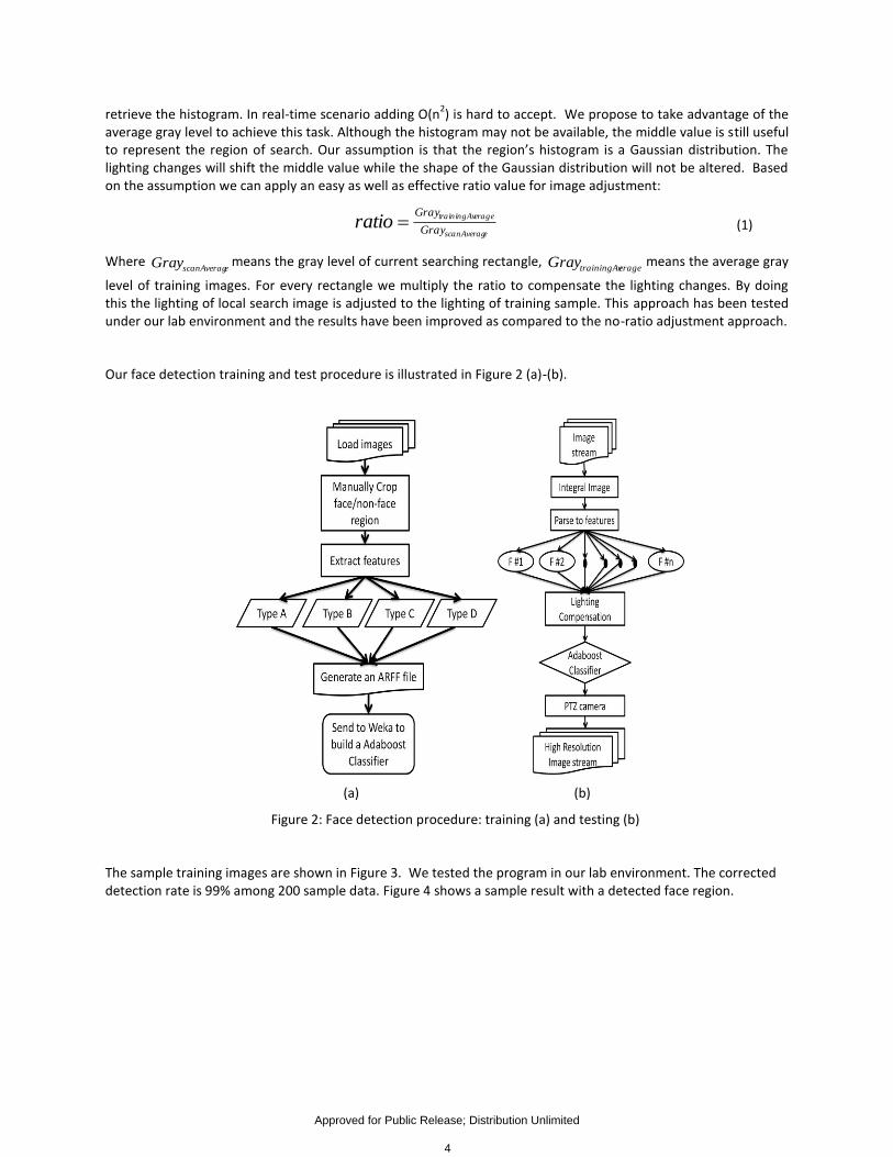
Our face detection training and test procedure is illustrated in Figure 2 (a)-(b).
(a) (b)
Figure 2: Face detection procedure: training (a) and testing (b)
The sample training images are shown in Figure 3. We tested the program in our lab environment. The corrected detection rate is 99% among 200 sample data. Figure 4 shows a sample result with a detected face region.
Approved for Public Release; Distribution Unlimited
4

Figure 3: Sample training data for face detection
Figure 4: Sample result: detected face region
2.2 Eye Detection Once the face is detected, we perform an eye detection program using a so-called topographic feature of eyes, which has been proposed in our work [56]. The basic idea is to create a terrain map from the gray-scale image (effectively treating it like a continuous 3D surface) and extracting “pit” locations as pupil candidates. The actual eye pair is chosen using a Gaussian Mixture Model (GMM) and certain heuristics (e.g. the eye candidates cannot be vertical). The approximate center of the two detected eye candidates is used as the focus of the pan-tilt-zoom camera. We do not use the mutual information tracking approach as did [56] and instead detect the eyes once every time the face is detected in the wide-angle view.
The algorithm has been developed for eye pair detection and tracking using geometric surface labeling and posterior probability maximization. Given a topographic surface of a face, each pixel is labeled according to its
intensity with respect to its neighboring pixels. Let zyxIyxf ),(),( , we can obtain the Hessian matrix H .
The eigen-values 1λ and 2λ of the Hessian matrix H can be used to detect the terrain types of the pixel. In our
implementation, we label each pixel into one of the 12 terrain types: peak, pit, ridge, ravine, ridge saddle, ravine saddle, convex hill, concave hill, convex saddle hill, concave saddle hill, slope hill, and flat. The experiment shows that the eye pupil center exhibits “peak” pattern. As such, any pixel that is labeled as peak point is classified as an eye center candidate.
Approved for Public Release; Distribution Unlimited
5
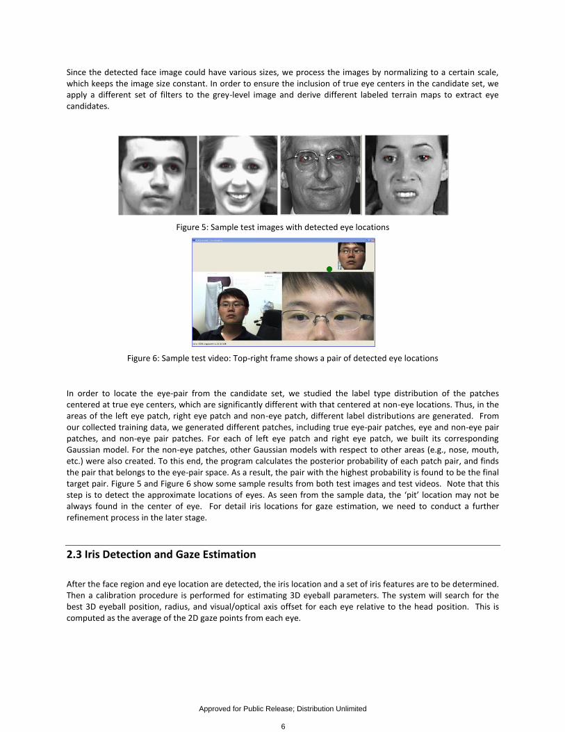
Since the detected face image could have various sizes, we process the images by normalizing to a certain scale, which keeps the image size constant. In order to ensure the inclusion of true eye centers in the candidate set, we apply a different set of filters to the grey-level image and derive different labeled terrain maps to extract eye candidates.
Figure 5: Sample test images with detected eye locations
Figure 6: Sample test video: Top-right frame shows a pair of detected eye locations
In order to locate the eye-pair from the candidate set, we studied the label type distribution of the patches centered at true eye centers, which are significantly different with that centered at non-eye locations. Thus, in the areas of the left eye patch, right eye patch and non-eye patch, different label distributions are generated. From our collected training data, we generated different patches, including true eye-pair patches, eye and non-eye pair patches, and non-eye pair patches. For each of left eye patch and right eye patch, we built its corresponding Gaussian model. For the non-eye patches, other Gaussian models with respect to other areas (e.g., nose, mouth, etc.) were also created. To this end, the program calculates the posterior probability of each patch pair, and finds the pair that belongs to the eye-pair space. As a result, the pair with the highest probability is found to be the final target pair. Figure 5 and Figure 6 show some sample results from both test images and test videos. Note that this step is to detect the approximate locations of eyes. As seen from the sample data, the ‘pit’ location may not be always found in the center of eye. For detail iris locations for gaze estimation, we need to conduct a further refinement process in the later stage.
2.3 Iris Detection and Gaze Estimation
After the face region and eye location are detected, the iris location and a set of iris features are to be determined. Then a calibration procedure is performed for estimating 3D eyeball parameters. The system will search for the best 3D eyeball position, radius, and visual/optical axis offset for each eye relative to the head position. This is computed as the average of the 2D gaze points from each eye.
Approved for Public Release; Distribution Unlimited
6
2.3.1 Iris Detection
We work on the red channel of the image, since the iris (unlike the surrounding skin areas) generally has very low red intensity values. We search for “highlight positions” on the eye (corresponding to specular reflections off the iris); these are regions containing enough dark pixels to be considered part of the iris while still having a high enough standard deviation to contain specular reflection points. To remove distracting points on glasses, we eliminate specular reflections that are long and thin (unlike iris highlights, which are generally equal in width and height). We equalize the histogram within the eye region to increase contrast. To determine the proper thresholds and parameters, we extract information from training video sequences we collected using a pan-tilt-zoom (PTZ) camera. Finally, we refine our initial iris estimate using a circular template in a very small area around the initial estimate.
2.3.2 Gaze Calibration
Our calibration procedure has two stages: the first acquires an estimate for the 3D eyeball center and radius, and the second iteratively refines our initial estimate while also extracting the optical/visual axis offset [58]. Note that each eyeball is handled independently during calibration.
2.3.2.1 Stage 1 Calibration (initial estimate)
At this point, we can get the 2D iris positions, and we assume the camera’s focal length is known; given a 3D eyeball radius r, we want to find an estimate for the 3D eyeball center E. Let us consider the camera center as the origin of a 3D coordinate system and the camera view direction as the z axis. Given a 2D pixel position and the camera’s focal length, we can get a 3D vector from the camera center through every 3D position that maps to our given 2D pixel point. This can be done simply by constructing a “world image plane,” a 3D plane which is perpendicular to the camera’s view axis and is far away enough such that 3D points in the plane have the same x and y coordinates as their projected 2D points. A 2D pixel point can then be converted to a 3D vector by setting its z coordinate to be the z depth of the world image plane. We operate under the assumption that, if the user is looking straight into the camera center, the eyeball center must be somewhere along a 3D vector starting at the camera center and going through the 2D iris center; that is, the gaze direction goes from the 3D eyeball center E to the 3D iris center E’ (this vector is known as the “optical axis”). Granted, this is not strictly true, since the correct gaze direction (called the “visual axis”) is a vector from the fovea (on the back of the eye) through the pupil, and this visual axis is offset from the optical axis by approximately 4-8° (we will refer to this angular difference as the optical/visual axis offset). However, we will correct for this in Stage 2.
The user first looks into the camera center and then at a calibration point P whose 3D location is known. This gives us 2D iris locations m1 and m2, respectively. These points are then converted into normalized unit vectors A and B. We want to find two points, E (the eyeball center) along vector A and E’ (the iris center) along vector B, such that the distance between them is r (the radius of the eyeball) and the vector between them points at P. Figure 7 illustrates this idea.
Approved for Public Release; Distribution Unlimited
7

Figure 7: Stage 1 calibration
Let ta and tb represent the lengths such that Ata = E and Btb = E’; we can then express our first constraint as follows:
rBtAt ba
(2)
Point E’ (or Btb) is the point of intersection between B and C (= Ata – P). This is equivalent to the point of intersection between B and a plane determined by point P and normal N = (A × B × C). So, our second constraint is as follows:
BN
PNtb
(3)
Given above equations (2) and (3) with two unknowns ta and tb, we can derive the following quartic formula and solve for ta:
0234
WVtUtTtSt aaaa (4)
where: (5)
(6) (7) (8) (9)
and:
(10)
(11)
(12)
Once we have ta, we can scale A by this value and get a 3D eyeball center estimate for a given radius. Although we could use a standard eyeball radius, we instead cycle through a range of 1.2cm to 1.3cm (in 1/10
th millimeter
increments) and get an eyeball estimate for each radius size. This corresponds to the natural range of eyeball radius sizes found in humans (1.2cm to 1.3cm). During the calibration procedure, we have the user look into the camera center first. Then, the user must track (with both the eyes and head) a calibration point moving from one corner of the screen to the other. A sample is collected for each position of the calibration point, and the second
22
2
2222
2
2
)(2
)(22
ZrW
YZrV
XYrXZBAZU
XYBAYZT
YS
BPBAZ
BABAY
PABAX
)(
)(
)(
Approved for Public Release; Distribution Unlimited
8

sample point is used to get our B vector (this sample point corresponds to a point very near either the upper-left or upper-right corner of screen, depending on which calibration step we are performing).
This is done twice:
1. The point moves from the upper-left corner of the screen to the lower-right corner, and these points are used
to calibrate the user’s left eye.
2. The point moves from the upper-right corner of the screen to the lower-left corner, and these points are used
to calibrate the user’s right eye.
We collect 40 calibration points per eye. For each eyeball estimate (and corresponding radius) and each of the calibration points, we use our gaze estimation approach to determine the estimated point of regard and get its distance from the true gaze (calibration) point. To increase sensitivity to error, we scale up each distance value to 1/10ths of a millimeter. These error distances are added together, and the eyeball estimate (and radius) with the smallest error is chosen. Note that this approach assumes that eyeball center (E), 3D iris center (E’), and 3D gaze point (P) are all coplanar, which may not be true if the user’s head moves during the calibration procedure; thus, we must adjust our vectors for head rotation and translation before performing our calibration calculations. We now have our initial 3D eyeball and radius estimate.
2.3.2.2 Stage 2 Calibration (refinement and visual axis offset)
Due to the optical/visual axis offset (as well as user error during calibration), our initial estimates can be off slightly from their true position. Therefore, we reset the radius to 0.0125 and find the best position and radius using the Nelder-Mead downhill simplex method. To ensure that the radius values remain reasonable, we add a penalty term if the radius should be outside of the range 1.2-1.3cm. The distance (in 1/1000s of a millimeter) is cubed and added to the total error term for a given position/radius estimate. We also add what we call the “optical error.” As we shall explain later, we use the iris contour points to determine gaze. Intuitively, the optical error corresponds to whether the iris contour points are arranged in a 3D circular pattern around the estimated gaze direction. Our gaze estimation procedure assumes that the vector from the eyeball center to each iris contour point has a set angle from the optical gaze direction (this corresponds to a known dot product value). For each of these iris contour vectors, the difference between the dot product of each vector with the estimated gaze direction and the expected dot product value is summed together. For incorrect eyeball positions, some iris contour points will not intersect with the eyeball sphere; for each missed point, a 1.0 is added to this sum. Finally, this sum is divided by the total number of iris contour points, and the value is multiplied by 10000 (to give it similar weight as the distance error).
For each position and radius estimate, we compute the expected iris radius and the visual axis offset. For each sample frame for the look-into-camera stage, we estimate the optical axis and average dot product by an extension of our gaze estimation approach. Once the optical axis is computed, the eye rotation pitch and yaw values can be ascertained, as well as the 3D iris center position. The visual axis is assumed to be the vector from the iris center to the camera center (the origin), and this vector is stored as a vector offset from the optical axis. The resulting expected dot product values and visual axes for each sample are averaged, and the final values are used for gaze estimation hereafter.
At this stage, we have the 3D eyeball center, which can be rotated and translated with head position and pose information, the 3D eyeball radius, and the visual axis offset.
Approved for Public Release; Distribution Unlimited
9
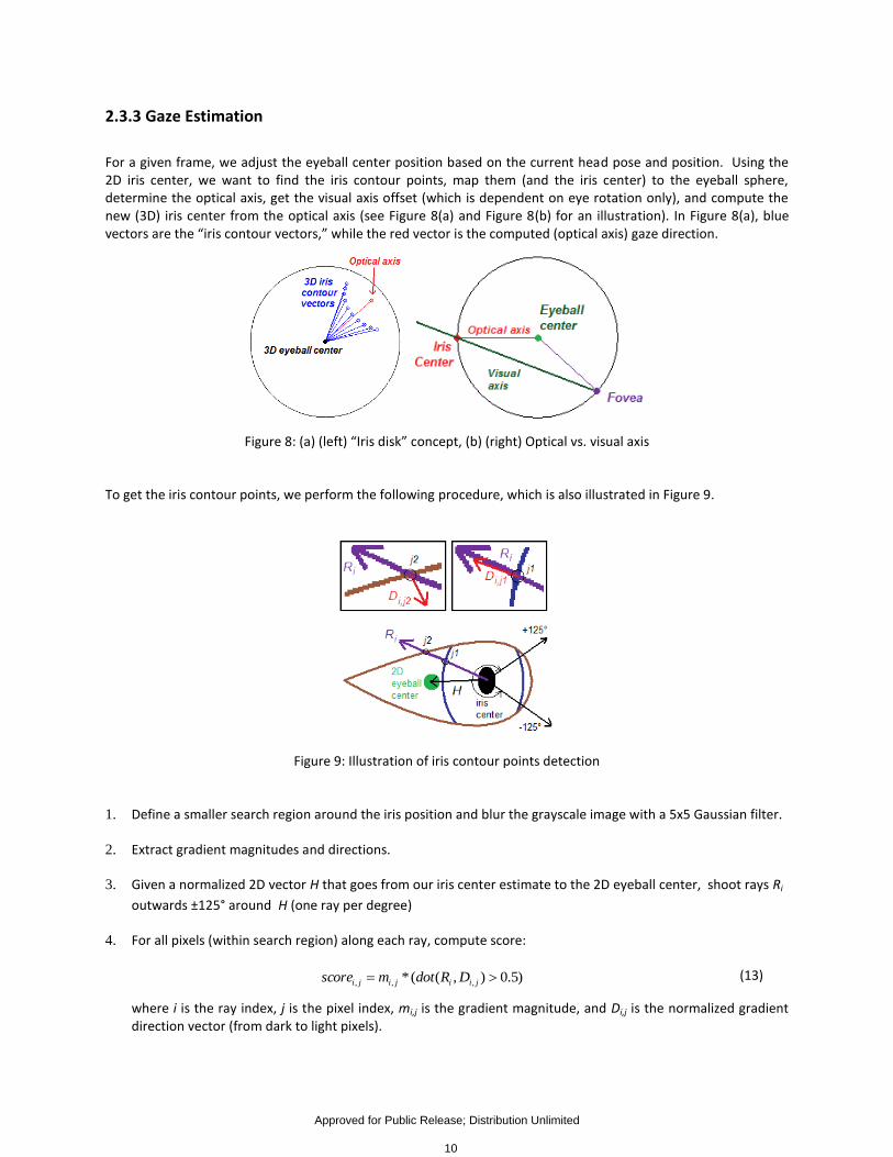
2.3.3 Gaze Estimation
For a given frame, we adjust the eyeball center position based on the current head pose and position. Using the 2D iris center, we want to find the iris contour points, map them (and the iris center) to the eyeball sphere, determine the optical axis, get the visual axis offset (which is dependent on eye rotation only), and compute the new (3D) iris center from the optical axis (see Figure 8(a) and Figure 8(b) for an illustration). In Figure 8(a), blue vectors are the “iris contour vectors,” while the red vector is the computed (optical axis) gaze direction.
Figure 8: (a) (left) “Iris disk” concept, (b) (right) Optical vs. visual axis
To get the iris contour points, we perform the following procedure, which is also illustrated in Figure 9.
Figure 9: Illustration of iris contour points detection
1. Define a smaller search region around the iris position and blur the grayscale image with a 5x5 Gaussian filter.
2. Extract gradient magnitudes and directions.
3. Given a normalized 2D vector H that goes from our iris center estimate to the 2D eyeball center, shoot rays Ri
outwards ±125° around H (one ray per degree)
4. For all pixels (within search region) along each ray, compute score:
)5.0),((* ,,, jiijiji DRdotmscore (13)
where i is the ray index, j is the pixel index, mi,j is the gradient magnitude, and Di,j is the normalized gradient direction vector (from dark to light pixels).
Approved for Public Release; Distribution Unlimited
10

5. The highest scoring pixel along each ray is chosen as a potential iris contour point.
6. Use an Active Appearance Model (AAM) that tracks the eye corners and eyelids to filter out erroneous points.
7. If we have over 10 points, break up remaining points into groups.
Here is the group processing procedure:
1. The points are ordered by angle around estimated iris center. For each point, check the 5 points ahead in the
list for the closest neighbor point. If the closest point is more than 1/8th
of the search region height away, do
not give this point a neighbor.
2. Form initial groups based on neighbor chains.
3. Remove all groups with less than 7 points.
4. For each remaining group, recursively fit the points to a line. If any point is more than 30% of the current
line’s length away, split this group and repeat the procedure. If any group has 5 points or less, stop processing
this group.
The AAM tracks the eye corners, the top and bottom eyelid points, and the iris center. To filter out iris contour points that may be part of the eyelids:
1. Create Catmull-Rom splines for the eyelid perimeter.
2. For each iris contour point, compute the vector from the AAM iris center to the contour point and get its
length L.
3. Determine the intersection point of this vector with the eyelid splines and get the length of this vector S.
4. Get D = S - L.
5. If D is less than 3.0, this point is an eyelid point and should not be used. Otherwise, keep the point.
To remove eye corner points:
1. Find the corner which the iris is closest to.
2. If any contour point is within 25% of the distance between the eye corners of the chosen eye corner, remove
this point.
We map 2D iris contour points to the eyeball sphere by converting them into 3D perspective vectors and intersecting them with the current eyeball sphere. We refer to a normalized vector going from the eyeball center to one of those intersection points as an “iris contour vector” Ci. Before we can perform gaze estimation, we need to estimate the 3D iris radius on the eyeball (or rather, the average dot product between the optical axis and each Ci). We use the information extracted during the look-into-camera phase of the calibration procedure; note that
Approved for Public Release; Distribution Unlimited
11

an approximation of the optical gaze vector can be extracted by intersecting the 2D iris center with the eyeball sphere, subtracting the eyeball center, and normalizing the result, giving us vector V. We get the average of the dot products (aveDot) between V and each Ci. In this way, we define an “iris disk.” Figure 8(a) illustrates this concept. This unique approach of mapping 2D contour points directly onto the 3D eyeball sphere allows for efficient detection of the gaze direction.
For gaze estimation, we first detect the iris center and contours and map these points to the eyeball sphere to ultimately get V and all Ci vectors, respectively. We want to find the optical axis G such that 1) it is parallel to V and 2) the dot product of G and each Ci is aveDot. Thus, we solve the following linear equations:
1
...
1
...
.........
.........
000
aveDot
aveDot
G
G
G
VVV
VVV
CCC
CCC
Z
Y
X
ZYX
ZYX
Z
N
Y
N
X
N
ZYX
(14)
Note that aveDot, V, and the constant 1 are repeated in their respective matrices N times, i.e., once for each contour vector.
We have found that repeating this procedure, using the new iris center estimate from the previous iteration, can give us more accurate results. So, we iterate our approach until either the distance between the endpoints of the normalized G vectors are within 1e-8 of each other or until we go through 20 iterations. To estimate the average dot product from the look-into-camera samples, we extend our approach like so:
1
...
1
0
...
0
0
............
0
1
............
1000
aveDot
G
G
G
VVV
VVV
CCC
CCC
Z
Y
X
ZYX
ZYX
Z
N
Y
N
X
N
ZYX
(15)
We do not iterate this procedure, however. To get the visual axis, we get the pitch and yaw rotation values from the optical axis G and rotate the visual axis offset accordingly. We intersect the optical axis with the eyeball sphere to get a new estimate for the 3D iris center, which we use for our gaze starting point. The visual axis is used as our final gaze direction.
Once we have our current 3D eyeball position and gaze vector, we must map this information to screen coordinates. We assume that the screen’s 3D position, size, and orientation are already known, and so the mapping is a simple ray-plane intersection. We use the average position of the two 2D gaze estimates as our final estimated point-of-regard. Figure 10 illustrates several examples from a real time video tracking sequence.
Approved for Public Release; Distribution Unlimited
12
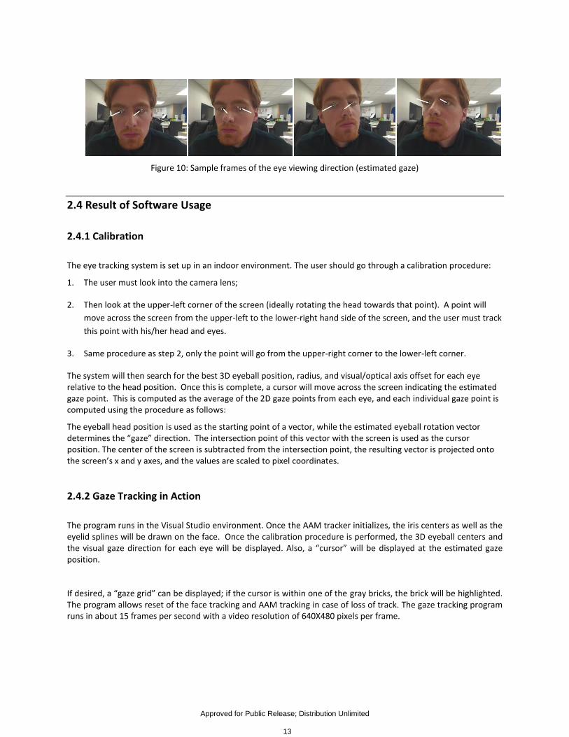
Figure 10: Sample frames of the eye viewing direction (estimated gaze)
2.4 Result of Software Usage
2.4.1 Calibration
The eye tracking system is set up in an indoor environment. The user should go through a calibration procedure:
1. The user must look into the camera lens;
2. Then look at the upper-left corner of the screen (ideally rotating the head towards that point). A point will
move across the screen from the upper-left to the lower-right hand side of the screen, and the user must track
this point with his/her head and eyes.
3. Same procedure as step 2, only the point will go from the upper-right corner to the lower-left corner.
The system will then search for the best 3D eyeball position, radius, and visual/optical axis offset for each eye relative to the head position. Once this is complete, a cursor will move across the screen indicating the estimated gaze point. This is computed as the average of the 2D gaze points from each eye, and each individual gaze point is computed using the procedure as follows:
The eyeball head position is used as the starting point of a vector, while the estimated eyeball rotation vector determines the “gaze” direction. The intersection point of this vector with the screen is used as the cursor position. The center of the screen is subtracted from the intersection point, the resulting vector is projected onto the screen’s x and y axes, and the values are scaled to pixel coordinates.
2.4.2 Gaze Tracking in Action
The program runs in the Visual Studio environment. Once the AAM tracker initializes, the iris centers as well as the eyelid splines will be drawn on the face. Once the calibration procedure is performed, the 3D eyeball centers and the visual gaze direction for each eye will be displayed. Also, a “cursor” will be displayed at the estimated gaze position.
If desired, a “gaze grid” can be displayed; if the cursor is within one of the gray bricks, the brick will be highlighted. The program allows reset of the face tracking and AAM tracking in case of loss of track. The gaze tracking program runs in about 15 frames per second with a video resolution of 640X480 pixels per frame.
Approved for Public Release; Distribution Unlimited
13
3 Hand Tracking: Method and Result
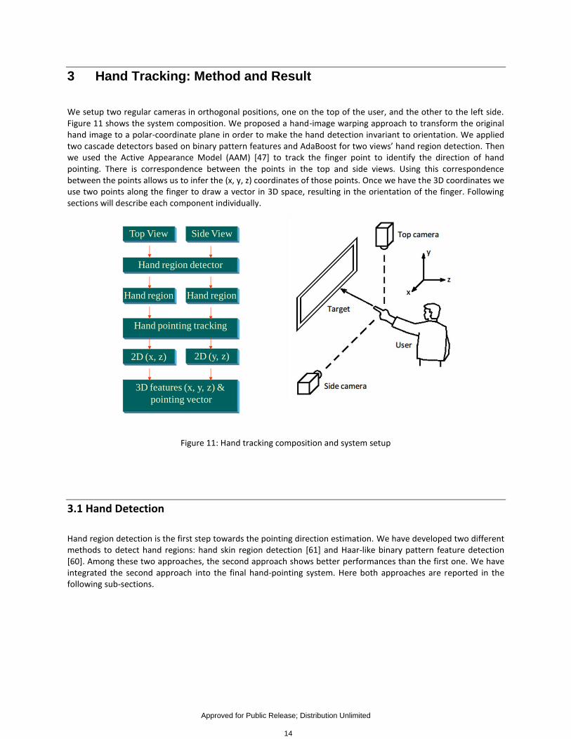
We setup two regular cameras in orthogonal positions, one on the top of the user, and the other to the left side. Figure 11 shows the system composition. We proposed a hand-image warping approach to transform the original hand image to a polar-coordinate plane in order to make the hand detection invariant to orientation. We applied two cascade detectors based on binary pattern features and AdaBoost for two views’ hand region detection. Then we used the Active Appearance Model (AAM) [47] to track the finger point to identify the direction of hand pointing. There is correspondence between the points in the top and side views. Using this correspondence between the points allows us to infer the (x, y, z) coordinates of those points. Once we have the 3D coordinates we use two points along the finger to draw a vector in 3D space, resulting in the orientation of the finger. Following sections will describe each component individually.
Figure 11: Hand tracking composition and system setup
3.1 Hand Detection
Hand region detection is the first step towards the pointing direction estimation. We have developed two different methods to detect hand regions: hand skin region detection [61] and Haar-like binary pattern feature detection [60]. Among these two approaches, the second approach shows better performances than the first one. We have integrated the second approach into the final hand-pointing system. Here both approaches are reported in the following sub-sections.
Top View Side View
Hand region detector
Hand region Hand region
Hand pointing tracking
2D (x, z) 2D (y, z)
3D features (x, y, z) &
pointing vector
Approved for Public Release; Distribution Unlimited
14

3.1.1 Hand Skin Region Detection The complex nature of the range of colors which constitute skin tones make it difficult to establish a firm set of values for image segmentation, and many types of methods for handling skin detection have been proposed. Variations in lighting further complicate the process of distinguishing skin from background colors. For these reasons, it is desirable to use machine learning approaches to establish a classifier which could accurately classify known examples of each class as well as provide reasonable guesses for colors not found in the training data.
A Bayesian classifier provides a simple, robust classification with a built-in classification confidence and can be used if a probability distribution function (PDF) can be established for each class. Since the actual PDF for the skin and background classes is not known, it is necessary to design an approximation of the PDF based on known data. A Gaussian Mixture Model (GMM) provides such an approximation. Therefore, the basis for hand detection is a Gaussian Mixture Model (GMM) based classifier for distinguishing skin colored pixels from background pixels. This is combined with a connected component analysis system in order to locate blocks of the image which contain significant amounts of skin colored pixels.
Our skin tone pixel segmentation uses a single Bayesian classifier based on the GMMs determined from a static set of training data. The classifier is fully computed ahead of time by a training program which processes a set of example images to extract the user-specified color components and train the GMMs accordingly. Once the training program has completed, the classifier remains fixed, and can be used for a separate hand detection application.
The features that were used by the classifier were taken from the YIQ color space. Like the HSV color space, YIQ consists of one component (Y) which corresponds to overall brightness, while the other two components (IQ) provide the color. By discarding the brightness component from the YIQ data, a certain degree of lighting invariance was gained.
To fit the specifications of a GMM to a set of data, we establish a fixed number of Gaussians for the GMM, and then fit each of the Gaussians using the classic Expectation-Maximization (EM) algorithm [57][58]. In order to locate potential hand regions in images, our system first uses a Bayesian classifier to identify skin tone areas. In initial implementations, every pixel of the image was processed by the classifier, however this proved to be too time consuming for real-time processing. In its current incarnation, the hand detector divides the image into a grid of blocks which are 8x8 pixels in size. The feature values of the pixels within each block are averaged, and these mean values are fed into the classifier. The resulting classification is then applied to all pixels within the block. The size of the block was empirically selected based on the criteria that it would sufficiently reduce processing time and that it would evenly divide common image sizes. Once the Bayesian classifier has identified each block as either skin or background (essentially producing a down-scaled classification image), the results are scanned for connected regions consisting of blocks with a skin confidence of at least 50%. We applied a skin-pixel based region-growing approach to detect the connected components of skin-regions. Connected regions whose width or height is below an empirically derived threshold are assumed to be false positives and are discarded. Any remaining connected regions are presumed to be hands. Some examples are shown in Figure 12. The top row shows video frames with the hand detected. The middle row shows the skin portion of the top row. The bottom row shows video frames with hands detected in a variable lighting background.
Approved for Public Release; Distribution Unlimited
15
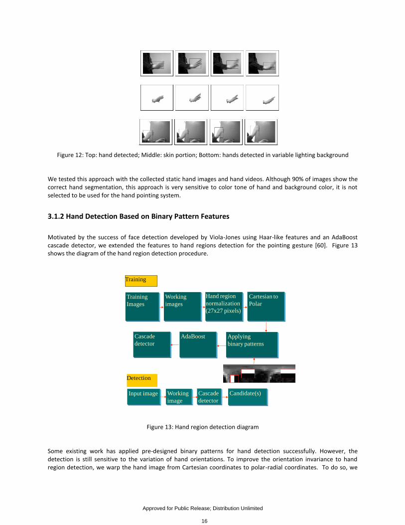
Figure 12: Top: hand detected; Middle: skin portion; Bottom: hands detected in variable lighting background
We tested this approach with the collected static hand images and hand videos. Although 90% of images show the correct hand segmentation, this approach is very sensitive to color tone of hand and background color, it is not selected to be used for the hand pointing system.
3.1.2 Hand Detection Based on Binary Pattern Features
Motivated by the success of face detection developed by Viola-Jones using Haar-like features and an AdaBoost cascade detector, we extended the features to hand regions detection for the pointing gesture [60]. Figure 13 shows the diagram of the hand region detection procedure.
Figure 13: Hand region detection diagram
Some existing work has applied pre-designed binary patterns for hand detection successfully. However, the detection is still sensitive to the variation of hand orientations. To improve the orientation invariance to hand region detection, we warp the hand image from Cartesian coordinates to polar-radial coordinates. To do so, we
Training
Images
Working
images
Hand region
normalization
(27x27 pixels)
Cartesian to
Polar
Applying
binary patterns
AdaBoostCascade
detector
Training
Input image Working
image
Cascade
detector
Candidate(s)
Detection
Approved for Public Release; Distribution Unlimited
16
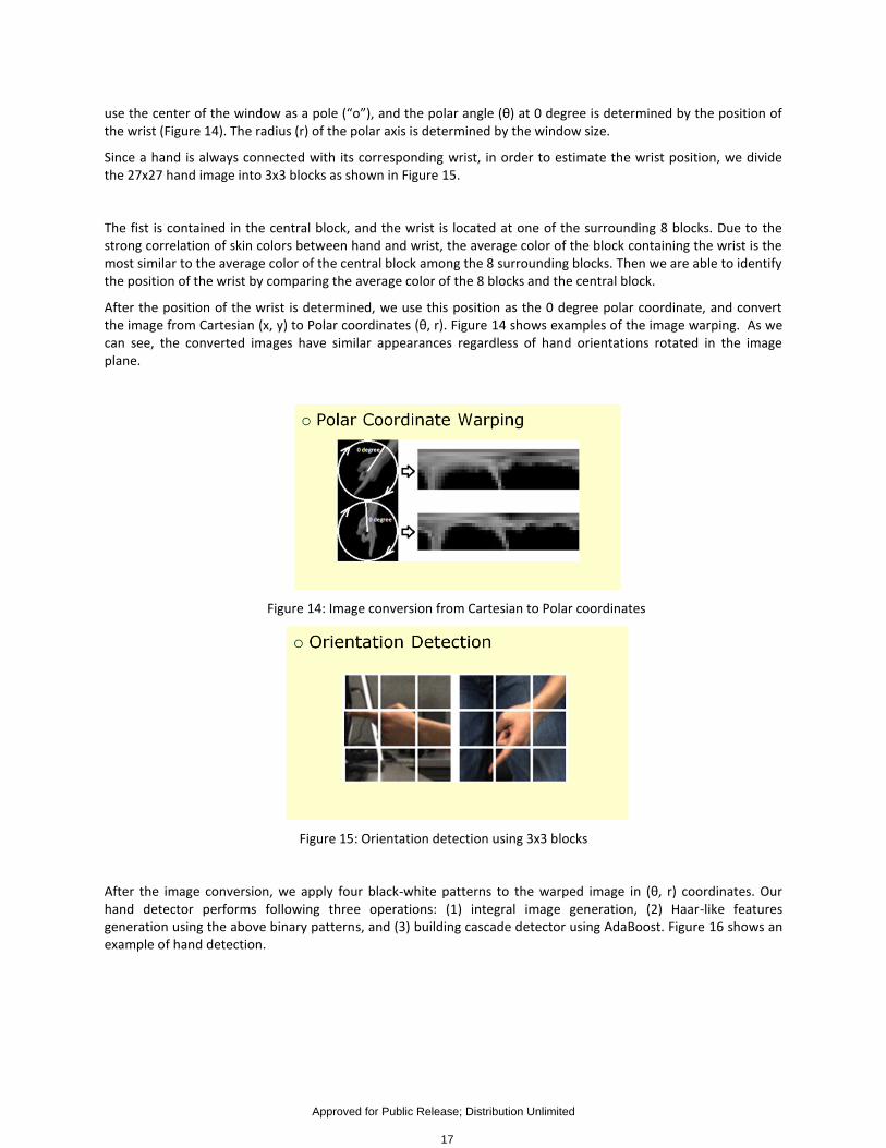
use the center of the window as a pole (“o”), and the polar angle (θ) at 0 degree is determined by the position of the wrist (Figure 14). The radius (r) of the polar axis is determined by the window size.
Since a hand is always connected with its corresponding wrist, in order to estimate the wrist position, we divide the 27x27 hand image into 3x3 blocks as shown in Figure 15.
The fist is contained in the central block, and the wrist is located at one of the surrounding 8 blocks. Due to the strong correlation of skin colors between hand and wrist, the average color of the block containing the wrist is the most similar to the average color of the central block among the 8 surrounding blocks. Then we are able to identify the position of the wrist by comparing the average color of the 8 blocks and the central block.
After the position of the wrist is determined, we use this position as the 0 degree polar coordinate, and convert the image from Cartesian (x, y) to Polar coordinates (θ, r). Figure 14 shows examples of the image warping. As we can see, the converted images have similar appearances regardless of hand orientations rotated in the image plane.
Figure 14: Image conversion from Cartesian to Polar coordinates
Figure 15: Orientation detection using 3x3 blocks
After the image conversion, we apply four black-white patterns to the warped image in (θ, r) coordinates. Our hand detector performs following three operations: (1) integral image generation, (2) Haar-like features generation using the above binary patterns, and (3) building cascade detector using AdaBoost. Figure 16 shows an example of hand detection.
Approved for Public Release; Distribution Unlimited
17
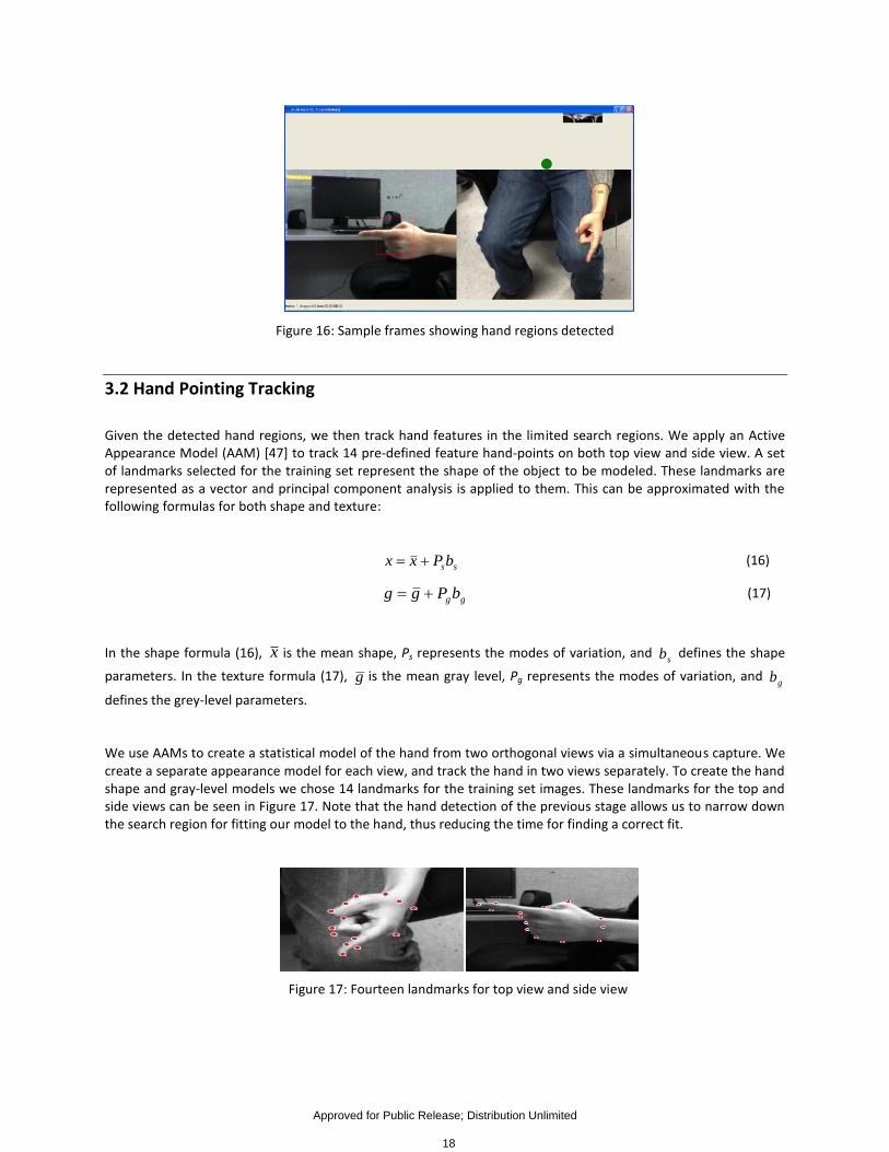
Figure 16: Sample frames showing hand regions detected
3.2 Hand Pointing Tracking
Given the detected hand regions, we then track hand features in the limited search regions. We apply an Active Appearance Model (AAM) [47] to track 14 pre-defined feature hand-points on both top view and side view. A set of landmarks selected for the training set represent the shape of the object to be modeled. These landmarks are represented as a vector and principal component analysis is applied to them. This can be approximated with the following formulas for both shape and texture:
ssbPxx (16)
ggbPgg (17)
In the shape formula (16), x is the mean shape, Ps represents the modes of variation, and sb defines the shape
parameters. In the texture formula (17), g is the mean gray level, Pg represents the modes of variation, and gb
defines the grey-level parameters.
We use AAMs to create a statistical model of the hand from two orthogonal views via a simultaneous capture. We create a separate appearance model for each view, and track the hand in two views separately. To create the hand shape and gray-level models we chose 14 landmarks for the training set images. These landmarks for the top and side views can be seen in Figure 17. Note that the hand detection of the previous stage allows us to narrow down the search region for fitting our model to the hand, thus reducing the time for finding a correct fit.
Figure 17: Fourteen landmarks for top view and side view
Approved for Public Release; Distribution Unlimited
18
In Figure 18 sampled frames of a testing video show detected hand regions (green blocks), tracked points (blue dots), and the estimated pointing vectors (red lines) from a top view (upper row) and a side view (lower row).
Figure 18: Detected hand regions, tracked points, and the estimated pointing vectors
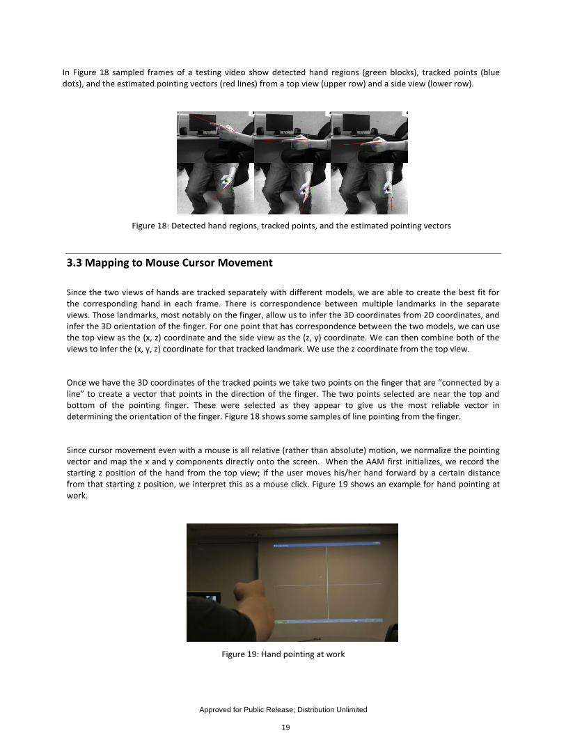
3.3 Mapping to Mouse Cursor Movement
Since the two views of hands are tracked separately with different models, we are able to create the best fit for the corresponding hand in each frame. There is correspondence between multiple landmarks in the separate views. Those landmarks, most notably on the finger, allow us to infer the 3D coordinates from 2D coordinates, and infer the 3D orientation of the finger. For one point that has correspondence between the two models, we can use the top view as the (x, z) coordinate and the side view as the (z, y) coordinate. We can then combine both of the views to infer the (x, y, z) coordinate for that tracked landmark. We use the z coordinate from the top view.
Once we have the 3D coordinates of the tracked points we take two points on the finger that are “connected by a line” to create a vector that points in the direction of the finger. The two points selected are near the top and bottom of the pointing finger. These were selected as they appear to give us the most reliable vector in determining the orientation of the finger. Figure 18 shows some samples of line pointing from the finger.
Since cursor movement even with a mouse is all relative (rather than absolute) motion, we normalize the pointing vector and map the x and y components directly onto the screen. When the AAM first initializes, we record the starting z position of the hand from the top view; if the user moves his/her hand forward by a certain distance from that starting z position, we interpret this as a mouse click. Figure 19 shows an example for hand pointing at work.
Figure 19: Hand pointing at work
Approved for Public Release; Distribution Unlimited
19

3.4 Result of Software Usage
The system is set up with a display screen or projector, and two cameras installed in two orthogonal views: one is mounted on the ceiling and one is placed on the left-side of the user. The program is run from command line (for example: track user [name] mode [calibration/running].)
3.4.1 Model Creation
For the system to work properly, separate models are needed for each view. The top-hand and side-hand AAM models need to be separated. A program will collect users’ hand data for creating AAM models for training. The training process could use a single person’s data or a group of people’s data. Currently, the person-dependent training/test is better than the person-independent training/test.
3.4.2 Calibration
To calibrate the system the user must point to the middle of the screen, top middle, left, bottom middle, and right sides of the screen. These can be done in any order. Once the user is pointing to that portion of the screen the following key presses are used to calibrate that point. 1. C – center
2. Up key – top middle
3. Down key – bottom middle
4. Left key – left
5. Right key – right
The program will save a calibration file to the machine so that the system will read in upon starting up.
3.4.3 Hand-Pointing in Action For the system to work properly, the system assumes the subject is performing hand-pointing gesture, and the hand is within the two cameras’ viewing ranges. The user will perform pointing actions after the hand features are detected at the beginning. The pointing cursor will show on the screen along the finger’s movement. The “push” action will highlight the region of selection. The pointing tracking program runs in about 15 frames per second with a video resolution of 640X480 pixels per frame.
Approved for Public Release; Distribution Unlimited
20

4 Conclusion and Future Development
By the end of this project, we have developed a proof-of-concept system for eye/gaze tracking and hand-pointing tracking. Such a system will facilitate the development of an advanced user interface for applications of data visualization, human machine/robot interaction, computer file system browsing, and so on. We will integrate the two components into a uniform framework through the combination of two gestures for human computer interaction in order to improve their reliability, usability, and flexibility. For the future development of the existing system, we will consider extending this project in the following aspects:
We will use non-orthogonal cameras with a more flexible setup to address the pointing estimation issue.
We will also refine the new algorithms for testing in the various imaging conditions in a certain distance.
We will further design a smart-room system with multiple cameras setup (e.g., 8 cameras) in order to address the issues of arbitrary view and occlusion issues.
We will develop a more intelligent interaction system by exploring body gestures and facial expression gestures with the 8-camera system.
We will design and develop a state-of-the-art visualization system with a human-centered interface (e.g., 3D file system structure and 3D file/scene visualization tool) by utilizing multi-modal modalities, including head, pose, eye, expressions, hand gesture, body gesture, voice, etc.
Approved for Public Release; Distribution Unlimited
21

5 References
[1] Zeng, Z., Pantic, M., Roisman, G.I., Huang, T.S. “A Survey of Affect Recognition Methods: Audio, Visual, and Spontaneous Expressions,” IEEE Transactions on Pattern Analysis and Machine Intelligence, vol. 31, no. 1, pp. 39-58, January 2009.
[2] Valstar, M. F., Pantic, M., Ambadar, Z., and Cohn, J. F. “Spontaneous vs. Posed Facial Behavior: Automatic Analysis of Brow Actions,” Proceedings of the 8th international Conference on Multimodal interfaces (ICMI '06, Banff, Alberta, Canada), New York, NY, pp 162-170, November 2006.
[3] Kapoor, A., Burleson, W., and Picard, R. W. “Automatic Prediction of Frustration,” International Journal of Human-Computer Studies, vol. 65, no. 8, pp 724-736, August 2007.
[4] Ji, Q., Lan, P., and Looney, C., “A Probabilistic Framework for Modeling and Real-Time Monitoring Human Fatigue,” IEEE Systems, Man, and Cybernetics Part A, vol. 36, no. 5, pp. 862-875, 2006.
[5] Cowie, R., Douglas-Cowie, E., Tsapatsoulis, N., Votsis, G., Kollias, S., Fellenz, W., and Taylor, J.G., “Emotion Reognition in Human-Computer Interaction,” IEEE Signal Processing Magazine, pp. 32-80, Jan. 2001.
[6] Valenti, R., Yucel, Z., and Gevers, T., “Robustifying Eye Center Localization by Head Pose Cues,” IEEE Workshop on Computer Vision and Pattern Recognition (CVPR'09), pp 612-618, 20-25 June 2009.
[7] Hansen, D. and Ji, Q., "In the Eye of the Beholder: A Survey of Models for Eyes and Gaze," IEEE Transactions on Pattern Analysis and Machine Intelligence, 23 Jan. 2009.
[8] Li, D., Winfield, D., and Parkhurst, D.J., “Starburst: A Hybrid Algorithm for Video-Based Eye Tracking Combining Feature-Based and Model-Based Approaches,” Proceedings of the Vision for Human-Computer Interaction Workshop, IEEE Computer Vision and Pattern Recognition Conference, pp 79-79, 2005.
[9] Yuille, A., Hallinan, P., and Cohen, D., “Feature Extraction from Faces Using Deformable Templates,” International Journal of Computer Vision, Volume 8, Issue 2, pp 99-111, 1992.
[10] Yingli Tian, Kanade, T., and Cohn, J.F., “Dual-State Parametric Eye Tracking,” Proceedings of the 4th IEEE International Conference on Automatic Face and Gesture Recognition, pp 110-115, 2000.
[11] Vezhnevets, V. and Degtiareva, A., “Robust and Accurate Eye Contour Extraction,” Proceedings of Graphicon, pp 81-84, 2003.
[12] Yen-Wei Chen and Kubo, K., “A Robust Eye Detection and Tracking Technique using Gabor Filters,” Proceedings of the Third International Conference on International Information Hiding and Multimedia Signal Processing (IIH-MSP 2007), pp 109-112, 2007.
[13] Peng Wang, Green, M.B., Ji, Q., and Wayman, J., “Automatic Eye Detection and Its Validation,” IEEE Workshop on Computer Vision and Pattern Recognition (CVPR'05), pp 164-164, June 2005.
[14] Xie, X., Sudhakar, R., and Zhuang, H., “On Improving Eye Feature-Extraction using Deformable Templates,” Pattern Recognition, Volume 27, Issue 6, pp 791-799, June 1994.
[15] Xie, X., Sudhakar, R., and Zhuang, H., “A Cascaded Scheme for Eye Tracking and Head Movement Compensation,” IEEE Transactions on Systems, Man, and Cybernetics, Part A, Volume 28, Issue 4, pp 487-490, July 1998.
[16] Hansen, D., Hansen, J.P., Nielsen, M., Johansen, A.S., and Stegmann, M.B., “Eye Typing using Markov and Active Appearance Models,” IEEE Workshop on Applications on Computer Vision, pp 132-136, 2003.
[17] Rodrigues Maia, J.G., de Carvalho Gomes, F., de Souza, O., “Automatic Eye Localization in Color Images,” Computer Graphics and Image Processing, 2007, SIBGRAPHI 2007, XX Brazilian Symposium on, pp 195-204, October 2007.
Approved for Public Release; Distribution Unlimited
22

[18] Merchant, J., Morrissette, R., and Porterfield, J. L., “Remote Measurement of Eye Direction Allowing Subject Motion Over One Cubic Foot of Space,” IEEE Transactions on Biomedical Engineering, Volume 21, Issue 4, pp 309-317, July 1974.
[19] Jr. White, K. P., Hutchinson, T.E., and Carley, J.M., “Spatially Dynamic Calibration of an Eye-Tracking System,” IEEE Transactions on Systems, Man, and Cybernetics, Volume 23, Issue 4, pp 1162-1168, 1993.
[20] Guestrin, E. and Eizenman, M., “General Theory of Remote Gaze Estimation using the Pupil Center and Corneal Reflections,” IEEE Transactions on Biomedical Engineering, Volume 53, Issue 6, pp 1124-1133, 2006.
[21] Ji, Q. and Zhu, Z., “Eye and Gaze Tracking for Interactive Graphic Display,” Proceedings of the 2nd Interational Symposium on Smart Graphics, pp 79-85, 2002.
[22] Zhu, Z., Ji, Q., and Bennett, K.P., “Nonlinear Eye Gaze Mapping Function Estimation via Support Vector Regression,” 18th International Conference on Pattern Recognition (ICPR'06), pp 1132-1135, 2006.
[23] Herpers, R., Michaelis, M., Lichtenauer, K., and Sommer, G., “Edge and Keypoint Detection in Facial Regions,” International Conference on Automatic Face and Gesture-Recognition, pp 212-217, 1996.
[24] Reinders, M., Koch, R., and Gerbrands, J., “Locating Facial Features in Image Sequences using Neural Networks,” Proceedings of the Second International Conference on Automatic Face and Gesture Recognition (FG'96) pp 230, 1996.
[25] Feng, G.C., and Yuen, P.C., “Multi-Cues Eye Detection on Gray Intensity Image,” Pattern Recognition, Volume 34, Issue 5, pp 1033-1046, May 2001.
[26] Kawato, S. and Tetsutani, N., “Detection and Tracking of Eyes for Gaze-Camera Control,” Proceedings of the 15th International Conference on Vision Interface, Volume 22, Issue 12, pp 1031-1038, October 2004.
[27] Kawato, S. and Tetsutani, N., “Real-Time Detection of Between-the-Eyes with a Circle Frequency Filter,” Proceedings of Asian Conference of Computer Vision 2002, Volume 2, pp 442-447, 2002.
[28] Hallinan, P.W., “Recognizing Human Eyes,” SPIE Proceedings, Vol. 1570: Geometric Methods in Computer Vision, pp 212-226, 1991.
[29] Pentland, A., Moghaddam, B., and Starner, T., “View-Based and Modular Eigenspaces for Face Recognition,” Proceedings of the IEEE Conference On Computer Vision and Pattern Recognition (CVPR'94), pp 84-91, June 1994.
[30] Huang, J. and Wechsler, H., “Eye Detection using Optimal Wavelet Packets and Radial Basis Functions (RBFs),” International Journal of Pattern Recognition and Artificial Intelligence, Volume 13, Issue 7, pp 1009-1026, 1999.
[31] Ishikawa, T., Baker, S., Matthews, I., and Kanade, T. “Passive Driver Gaze Tracking with Active Appearance Models,” Proceedings of the 11th World Congress on Intelligent Transportation Systems, October 2004.
[32] Ji, Q. and Yang, X., “Real-Time Eye, Gaze, and Face Pose Tracking for Monitoring Driver Vigilance,” Real-Time Imaging, Volume 8, Issue 5, pp 357-377, 2002.
[33] Nguyen, K., Wagner, C.., Koons, D., and Flickner, M., “Differences in the Infrared Bright Pupil Response of Human Eyes,” Proceedings of the Symposium on Eye Tracking Research & Applications (ETRA'02), pp 133-138, 2002.
[34] Zhu, Z., Ji, Q., and Fujimura, K., “Combining Kalman Filtering and Mean Shift for Real Time Eye Tracking,” Proceedings of the 16th International Conference on Pattern Recognition (ICPR'02), Volume 4, pp 318-321, 2002.
[35] Reisfeld, D. and Yeshurun, Y., “Robust Detection of Facial Features by Generalized Symmetry,” Proceedings of the 11th International Conference on Pattern Recognition, pp 117-120, 1992.
[36] Chau, M., and Betke, M. 2005. “Real Time Eye Tracking and Blink Detection with USB Cameras,” Tech. Rep. 2005-12, Boston University Computer Science.
Approved for Public Release; Distribution Unlimited
23

[37] Kolakowski, S. and Pelez, J., “Compensating for Eye Tracker Camera Movement,” Proceedings of the 2006 Symposium on Eye Tracking Research & Applications (ETRA'06), pp 79-85, 2006.
[38] Zhu, Z., and Ji, Q., “Novel Eye Gaze Tracking Techniques under Natural Head Movement,” IEEE Transactions on Biomedical Engineering, Volume 54, Issue 12, pp 2246-2260, 2007.
[39] Villanueva, A. and Cabeza, R., “Models for Gaze Tracking Systems,” Journal on Image and Video Processing, Volume 2007, Issue 3, Article No. 4, 2007.
[40] Yoo, D.H. and Chung, M.J., “A Novel Non-Intrusive Eye Gaze Estimation using Cross-Ratio under Large Head Motion,” Computer Vision and Image Understanding, Volume 98, Issue 1, pp 25-51, April 2005.
[41] Coutinho, F.L., and Morimoto, C.H., “Free Head Motion Eye Gaze Tracking using a Single Camera and Multiple Light Sources,” 19th Brazilian Symposium on Computer Graphics and Image Processing (SIBGRAPHI'06), pp 171-178, October 2006.
[42] Kang, J., Guestrin, E., and Eizenman, E., “Investigation of the Cross-Ratios Method for Point-of-Gaze Estimation,” IEEE Transactions on Biometical Engineering, Volume 55, Issue 9, pp 2293-2302, September 2008.
[43] Boening, G., Bartl, K., Dera, T., Bardins, S., Schneider, E., and Brandt, T., “Mobile Eye Tracking as a Basis for Real-Time Control of a Gaze Driven Head-Mounted Video Camera,” Proceedings of the 2006 Symposium on Eye Tracking Research & Applications (ETRA'06), pg 56-56, 2006.
[44] Kar-Han Tan, Kriegman, D.J., and Ahuja, N., “Appearance-Based Eye Gaze Estimation,” Proceedings of Sixth IEEE Workshop on Applications of Computer Vision (WACV'02), pp 191-195, 2002.
[45] Wang, J.G., Sung, E., and Venkateswarlu, R. “Estimating the Eye Gaze from One Eye,” Computer Vision and Image Understanding, Volume 98, Issue 1, pp 83-103, April 2005.
[46] C. Colombo et al., Visual capture and understanding of hand pointing actions in a 3-D environment, IEEE Trans. on SMC-B 33(4), 2003. pp. 677-686.
[47] T. Cootes, G. Edwards, and C. Taylor. Active appearance models. IEEE PAMI, 23(6): 681-685, 2001.
[48] N. Jojic et al, Detection and estimation of pointing gestures in real-time stereo sequences, In IEEE FGR’00.
[49] M. Kölsch and M. Turk. Analysis of rotational robustness of hand detection with a viola-jones detector. ICPR 2004.
[50] M. Lee, D. Weinshall, et al. A computer vision system for on-screen item selection, IEEE CVPR 2001.
[51] C. Manders, F. Farbiz, et al. Robust hand tracking using a skin tone and depth joint probability model. FGR, 2008.
[52] T. Nguyen, N. Binh, and H. Bischof. An active boosting-based learning framework for real-time hand detection. IEEE FGR, 2008.
[53] A. Utsumiy, et al, Hand detection and tracking using pixel value distribution model for multiple-camera-based gesture interactions. IEEE CVPR, 2001.
[54] P. Viola and M. Jones. Robust real-time face detection, International J. of Computer Vision 57(2)137–154, 2004.
[55] R. Wang and J. Popovic, Real-time hand-tracking with a color glove, SIGGRAPH 2009.
[56] J. Wang, L. Yin, and J. Moore, “Using geometric property of topographic manifold to detect and track eyes for human computer interaction”, ACM TOMCCAP, vol.3, no. 4, pp. 1-19, Dec. 2007.
[57] Bilmes, J.A.: A gentle tutorial of the em algorithm and its application to parameter estimation for gaussian mixture and hidden markov models. Technical Report TR-97-021, International Computer Science Institute and Computer Science Division U.C. Berkeley, Berkeley CA (1998)
Approved for Public Release; Distribution Unlimited
24

[58] Paalanen, P.: Bayesian classification using gaussian mixture model and EM estimation: implementation and comparisons. Information Technology Project (2004)
[59] Michael Reale, Terry Hung, and Lijun Yin, “Pointing with the eyes: gaze estimation using a static/active camera system and 3D iris model”, IEEE International Conference on Multimedia and Expo (ICME 2010), July 2010, Singapore. (15% acceptance rate)
[60] Kaoning Hu, Shaun Canavan, and Lijun Yin, “Hand pointing estimation for human computer interaction based on two orthogonal views”, IEEE/IAPR International Conference on Pattern Recognition (ICPR 2010), August 2010, Istanbul, Turkey.
[61] Gabriel Yoder and Lijun Yin, “Real-time hand detection and gesture tracking with GMM and model adaptation", 5th International Symposium on Visual Computing, Dec. 2009. Las Vegas, NV
[62] Shaun Canavan and Lijun Yin, Dynamic face appearance modeling and sight direction estimation based on local region tracking and scale-space topo-representation, IEEE International Conference on Multimedia and Expo (ICME 2009), June 2009. New York, NY (23% acceptance rate)
[63] Michael Reale, Terry Hung, and Lijun Yin, “Viewing Direction Estimation Based on 3D Eyeball Construction for HRI”, IEEE CVPR workshop on Computer Vision for Human Robot Interaction in conjunction with IEEE International Conference on Computer Vision and Pattern Recognition (CVPR 2010), June 2010, San Francisco, CA
Approved for Public Release; Distribution Unlimited
25

6 List of Symbols/Abbreviations/Acronyms
AAM Active Appearance Model AdaBoost Adaptive Boosting Algorithm EM Expectation-Maximization GMM Gaussian Mixture Model IR Infra-Red PDF Probability Distribution Function PoG Point of Regard PTZ Pan-Tilt-Zoom
Weka Waikato Environment for Knowledge Analysis
Approved for Public Release; Distribution Unlimited
26