approved for public release; … for public release; distribution unlimited.. stinfo copy . air...
TRANSCRIPT
APPROVED FOR PUBLIC RELEASE; DISTRIBUTION UNLIMITED.
STINFO COPY
AIR FORCE RESEARCH LABORATORY INFORMATION DIRECTORATE
END-TO-END SERVICE ORIENTED ARCHITECTURES (SOA) SECURITY PROJECT
PURDUE UNIVERSITY
FEBRUARY 2012 FINALTECHNICAL REPORT
ROME, NY 13441 UNITED STATES AIR FORCE AIR FORCE MATERIEL COMMAND
AFRL-RI-RS-TR-2012-049
NOTICE AND SIGNATURE PAGE Using Government drawings, specifications, or other data included in this document for any purpose other than Government procurement does not in any way obligate the U.S. Government. The fact that the Government formulated or supplied the drawings, specifications, or other data does not license the holder or any other person or corporation; or convey any rights or permission to manufacture, use, or sell any patented invention that may relate to them. This report was cleared for public release by the 88th ABW, Wright-Patterson AFB Public Affairs Office and is available to the general public, including foreign nationals. Copies may be obtained from the Defense Technical Information Center (DTIC) (http://www.dtic.mil). AFRL-RI-RS-TR-2012-049 HAS BEEN REVIEWED AND IS APPROVED FOR PUBLICATION IN ACCORDANCE WITH ASSIGNED DISTRIBUTION STATEMENT. FOR THE DIRECTOR: /s/ /s/ ASHER D. SINCLAIR JULIE BRICHACEK, Chief Work Unit Manager Information Systems Division
Information Directorate This report is published in the interest of scientific and technical information exchange, and its publication does not constitute the Government’s approval or disapproval of its ideas or findings.
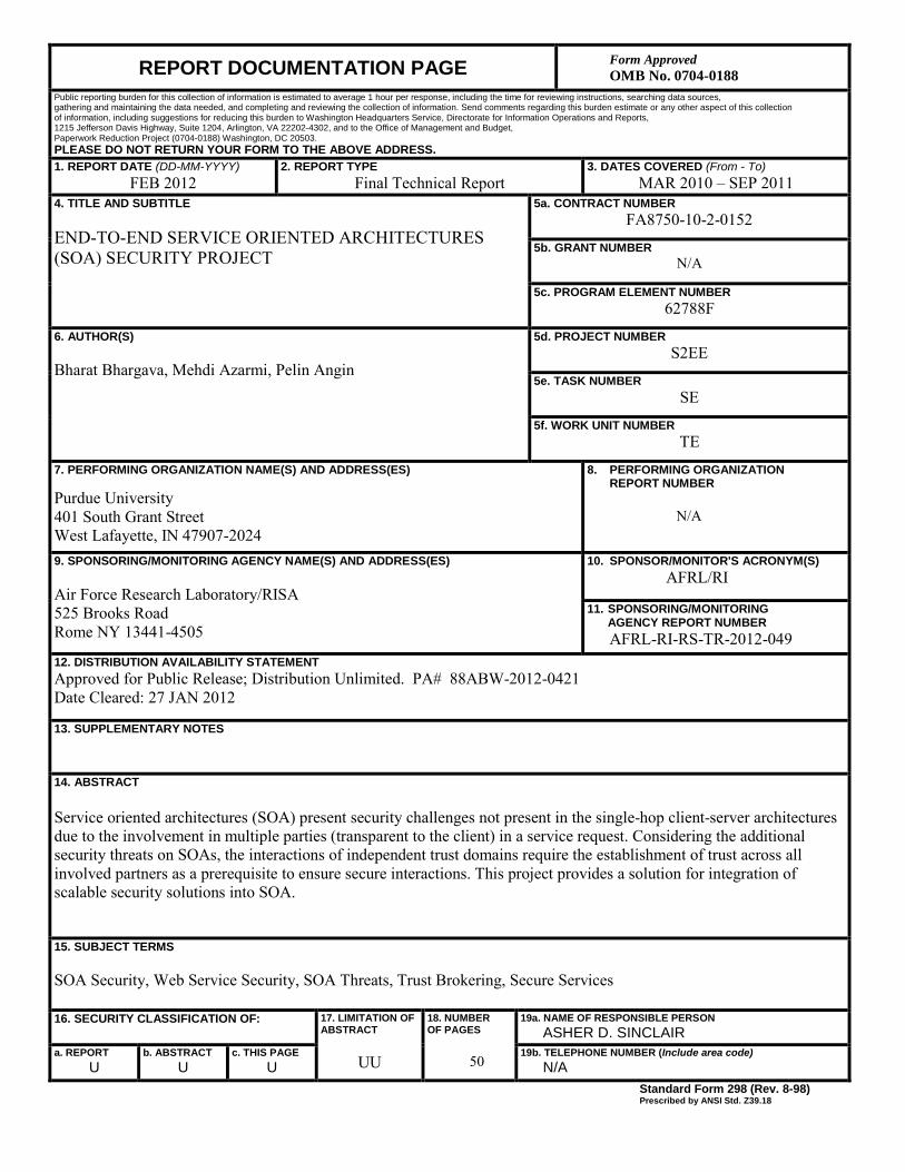
REPORT DOCUMENTATION PAGE Form Approved OMB No. 0704-0188
Public reporting burden for this collection of information is estimated to average 1 hour per response, including the time for reviewing instructions, searching data sources, gathering and maintaining the data needed, and completing and reviewing the collection of information. Send comments regarding this burden estimate or any other aspect of this collection of information, including suggestions for reducing this burden to Washington Headquarters Service, Directorate for Information Operations and Reports, 1215 Jefferson Davis Highway, Suite 1204, Arlington, VA 22202-4302, and to the Office of Management and Budget, Paperwork Reduction Project (0704-0188) Washington, DC 20503. PLEASE DO NOT RETURN YOUR FORM TO THE ABOVE ADDRESS. 1. REPORT DATE (DD-MM-YYYY)
FEB 2012 2. REPORT TYPE
Final Technical Report 3. DATES COVERED (From - To)
MAR 2010 – SEP 2011 4. TITLE AND SUBTITLE END-TO-END SERVICE ORIENTED ARCHITECTURES (SOA) SECURITY PROJECT
5a. CONTRACT NUMBER FA8750-10-2-0152
5b. GRANT NUMBER N/A
5c. PROGRAM ELEMENT NUMBER 62788F
6. AUTHOR(S) Bharat Bhargava, Mehdi Azarmi, Pelin Angin
5d. PROJECT NUMBER S2EE
5e. TASK NUMBER SE
5f. WORK UNIT NUMBER TE
7. PERFORMING ORGANIZATION NAME(S) AND ADDRESS(ES)
Purdue University 401 South Grant Street West Lafayette, IN 47907-2024
8. PERFORMING ORGANIZATION REPORT NUMBER N/A
9. SPONSORING/MONITORING AGENCY NAME(S) AND ADDRESS(ES) Air Force Research Laboratory/RISA 525 Brooks Road Rome NY 13441-4505
10. SPONSOR/MONITOR'S ACRONYM(S) AFRL/RI
11. SPONSORING/MONITORING AGENCY REPORT NUMBER AFRL-RI-RS-TR-2012-049
12. DISTRIBUTION AVAILABILITY STATEMENT Approved for Public Release; Distribution Unlimited. PA# 88ABW-2012-0421 Date Cleared: 27 JAN 2012
13. SUPPLEMENTARY NOTES
14. ABSTRACT Service oriented architectures (SOA) present security challenges not present in the single-hop client-server architectures due to the involvement in multiple parties (transparent to the client) in a service request. Considering the additional security threats on SOAs, the interactions of independent trust domains require the establishment of trust across all involved partners as a prerequisite to ensure secure interactions. This project provides a solution for integration of scalable security solutions into SOA.
15. SUBJECT TERMS SOA Security, Web Service Security, SOA Threats, Trust Brokering, Secure Services
16. SECURITY CLASSIFICATION OF: 17. LIMITATION OF ABSTRACT
UU
18. NUMBER OF PAGES
50
19a. NAME OF RESPONSIBLE PERSON ASHER D. SINCLAIR
a. REPORT U
b. ABSTRACT U
c. THIS PAGE U
19b. TELEPHONE NUMBER (Include area code) N/A
Standard Form 298 (Rev. 8-98) Prescribed by ANSI Std. Z39.18
i
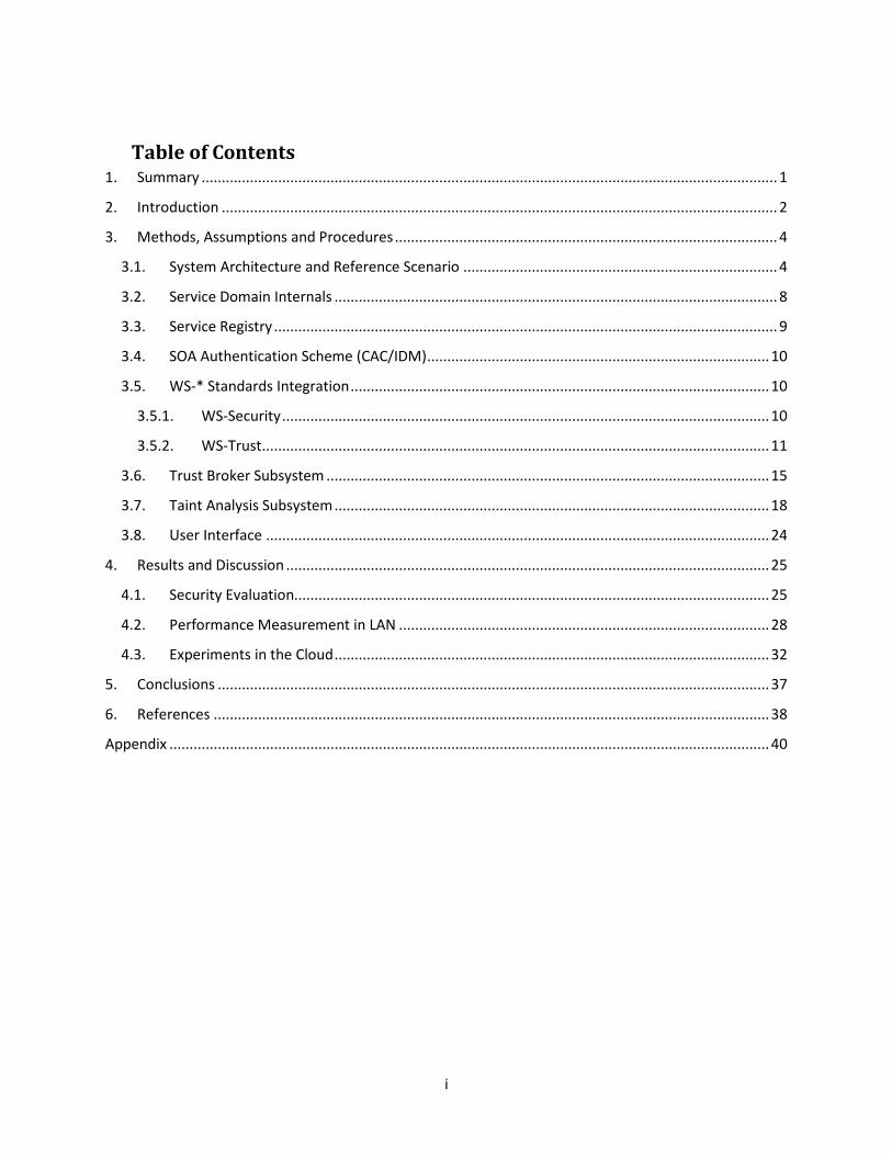
Table of Contents 1. Summary ............................................................................................................................................... 1
2. Introduction .......................................................................................................................................... 2
3. Methods, Assumptions and Procedures ............................................................................................... 4
3.1. System Architecture and Reference Scenario .............................................................................. 4
3.2. Service Domain Internals .............................................................................................................. 8
3.3. Service Registry ............................................................................................................................. 9
3.4. SOA Authentication Scheme (CAC/IDM) ..................................................................................... 10
3.5. WS-* Standards Integration ........................................................................................................ 10
3.5.1. WS-Security ......................................................................................................................... 10
3.5.2. WS-Trust .............................................................................................................................. 11
3.6. Trust Broker Subsystem .............................................................................................................. 15
3.7. Taint Analysis Subsystem ............................................................................................................ 18
3.8. User Interface ............................................................................................................................. 24
4. Results and Discussion ........................................................................................................................ 25
4.1. Security Evaluation...................................................................................................................... 25
4.2. Performance Measurement in LAN ............................................................................................ 28
4.3. Experiments in the Cloud ............................................................................................................ 32
5. Conclusions ......................................................................................................................................... 37
6. References .......................................................................................................................................... 38
Appendix ..................................................................................................................................................... 40

ii
List of Figures
Figure 1 AF SOA scenario .............................................................................................................................. 3 Figure 2 SOA High-Level End-to-End Architecture ........................................................................................ 5 Figure 3 Service Domain Internals ................................................................................................................ 9 Figure 4 Typical Message Flow with WS-Security [WSS2] .......................................................................... 11 Figure 5 PicketLink Security Token Service [WST4] .................................................................................... 13 Figure 6 Trust Broker Structure .................................................................................................................. 16 Figure 7 Using Taint Analysis to detect Service Invocations ....................................................................... 20 Figure 8 Interaction of Taint Analysis with Trust Broker ............................................................................ 21 Figure 9 User Interface ............................................................................................................................... 25 Figure 10 Setting for Attack Scenario ......................................................................................................... 26 Figure 11 TCPMon modification for security experiments ......................................................................... 27 Figure 12 Baseline experiment setup in the local area network ................................................................ 28 Figure 13 Taint analysis experiment setup in the local area network ........................................................ 29 Figure 14 Response time vs number of simultaneous requests for the first 300 invocations of the Evacuation Timer service ............................................................................................................................ 30 Figure 15 Response time vs number of simultaneous requests for the first 350 invocations of the Evacuation Timer service ............................................................................................................................ 30 Figure 16 Response time vs. number of simultaneous requests for the first 400 invocations of the Evacuation Timer service ............................................................................................................................ 31 Figure 17 WS-Security overhead on response time for invocations of the taint analysis equipped Evacuation Timer service ............................................................................................................................ 32 Figure 18 Baseline experiment setup in the Amazon EC2 .......................................................................... 32 Figure 19 Taint analysis experiment setup in the Amazon EC2 .................................................................. 33 Figure 20 Response time vs number of simultaneous requests for the first 400 service invocations in the Amazon EC2 ................................................................................................................................................ 33 Figure 21 Response time for fixed rate session feedback requests to a Trust Broker deployed in the Amazon EC2 ................................................................................................................................................ 34 Figure 22 Response time for the first 400 session feedback requests to a Trust Broker deployed in the Amazon EC2 ................................................................................................................................................ 35 Figure 23 Response time for the first 400 session history requests to a Trust Broker deployed in the Amazon EC2 ................................................................................................................................................ 35 Figure 24 Response time for the first 300 session history requests to a Trust Broker deployed in the Amazon EC2 ................................................................................................................................................ 36
LIST OF TABLES
Table 1 TB Database Schema ...................................................................................................................... 19
APPROVED FOR PUBLIC RELEASE; DISTRIBUTION UNLIMITED.
1
1. Summary
Service oriented architectures (SOA) present security challenges not present in the single-hop client-server architectures due to the involvement in multiple parties (transparent to the client) in a service request. Considering the additional security threats on SOAs, the interactions of independent trust domains require the establishment of trust across all involved partners as a prerequisite to ensure secure interactions. This project provides a solution for integration of scalable security solutions into SOA.
The security challenges in SOA (based on BAA Announcement [BAA1]), addressed in this project, are the following:
A. Authentication and authorization does not take place across intended end points, such as between the requestor and service provider.
B. Termination at intermediate steps of service execution exposes messages to hostile threats, for example, Man-in-the-Middle attacks.
C. External services are not verified or validated dynamically (uninformed selection of services by user).
D. User has no control on external service invocation within an orchestration or through a service in another service domain.
E. Violations and malicious activities in a trusted service domain remain undetected. The first two items (A and B) are explicitly mentioned in the BAA [BAA1]. The following three items (C, D, and E) are inferred from the security analysis of SOA, which are interrelated to the first two items.
To address these challenges, we designed and implemented:
• A comprehensive security architecture for SOA. • A novel service invocation control mechanism for SOA using dynamic taint analysis (TA). • A trust broker (TB) system that maintains information about trustworthiness of services and
categorizes them. TB is used for dynamic validation and verification of services and keeps track of history of service invocations.
• Functionality for using widely adopted Web service standards (WS-Security, WS-Trust, WS-Policy) for enterprise Air Force systems.
• A secure end-to-end message origin authentication for Web service client requests and Web service providers to ensure confidentiality and integrity—even in the presence of man-in-the-middle attacks. This solution is compatible with customary common access card (CAC) interactions.
This document details the design, implementation and evaluation of the solution proposed for providing end-to-end security in a SOA environment.

APPROVED FOR PUBLIC RELEASE; DISTRIBUTION UNLIMITED.
2
2. Introduction
Security is a challenging issue in service oriented architectures (SOAs) because the SOAs stress on machine-to-machine interactions, while most of the IT security mechanisms are based on human-to-machine interaction. Authentication and authorization become more challenging in this environment. Web services have no innate ability to track who is using them or who is permitted to use them. It is not possible to stop unwanted listening in and message interception by attackers. The unsecured SOA presents hackers with the ability to eavesdrop on SOAP message traffic and see information that may be private. On the other hand it is not possible to secure the unknown third parties in a SOA because of the architecture's open nature. So, it is possible for secondary or tertiary services-the partners of your partners- to access an unsecured SOA.
In Figure 1, these challenges are briefly depicted. In this figure, the current Air Force infrastructure is shown above the thick dashed line. In this architecture, all services are available in the local trusted service domain and everything is under the control of domain A. A typical scenario is as follows:
• Client at the edge platform decides to use a service from domain A. He will use his CAC (common access card) to authenticate into the system.
• The security token is sent to the IDM (identity management system) for validation check. • If the user is authorized, IDM gives permission to the requested service (e.g. MX or mail service)
for communication with the user. • New security token (which is created temporarily for the current service session) is sent back to
the user and the user can use the service.
In a class of extended scenarios (use cases) the services in service domain A may want to use external services, which are not in the same local trust boundary. In this case, as shown in Figure 1, other components come in the picture (below the dashed red line). This figure shows that when service domain A (e.g. Air Force service portal) tries to access other governmental or public services (from external domains), it will lose track of end-to-end security. This figure shows that end points can be accessible to the client directly. We address these issues with a Trust Broker server and taint analysis modules installed in external service domains as discussed in the Sections 3.6 and 3.7 below.
The rest of this document is organized as follows: Section 3 presents the end-to-end security solution proposed in the project and describes the details of the prototype implemented; Section 4 presents results of the security and performance evaluation of the proposed solution and Section 5 provides the conclusions drawn.

APPROVED FOR PUBLIC RELEASE; DISTRIBUTION UNLIMITED.
3
Figure 1 AF SOA scenario

APPROVED FOR PUBLIC RELEASE; DISTRIBUTION UNLIMITED.
4
3. Methods, Assumptions and Procedures
This section presents the design and implementation details of various components of the proposed security architecture prototype.
3.1. System Architecture and Reference Scenario The end-to-end SOA infrastructure consists of a client making a request to the initial trusted services/domain and that service can make a service call to another service from a trusted domain or an untrusted public domain.
The definition of a trusted service, in the scope of this project, is any of these items:
• A service consumer or client itself • A Web service which is deployed in an environment controlled by the organization such as Air
Force and a taint analysis module is deployed in that service domain. • Any other service domains that give permission for deployment of a taint analysis (TA) module.
Note: The communication protocol between a trusted service and the Trust Broker module is transparent to the service and is maintained by the TA module.
All other services are untrusted services, which are those mainly under the control of external entities (Yahoo, Amazon, Google, etc.). Standard communication protocols used for these services are SOAP over HTTPS with WS-* support [CDK02].
APPROVED FOR PUBLIC RELEASE; DISTRIBUTION UNLIMITED.
5
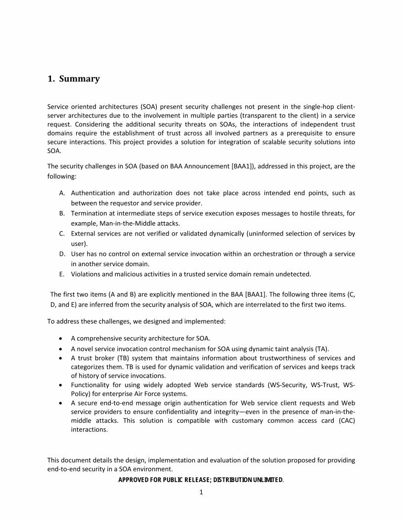
Figure 2 SOA High-Level End-to-End Architecture
Below we describe a reference scenario used in this project. The information flow depicted in Figure 2 is as follows (the event sequence numbers are shown in red):
1. Global UDDI Registry request • The client/service consumer (SoapUI/Custom Client) queries UDDI (please see section
3.3 for details about UDDI) with the appropriate search parameters like service category and then UDDI returns a set of services matching the query to the client.
2. Client sends a refined list of services to the Trust Broker module • The Client makes a selection from the set of services returned by the UDDI according to
its requirements by comparing various SLA attributes. Here we are trying to secure a system end-to-end, so the very obvious requirement for making this selection is that the client chooses a trusted service or a service with the highest trust level from this set of services.
• To achieve this, we introduce a new component called Trust Broker (TB), which is responsible for giving the client a trust value for a particular service.
• The Client queries the TB with an initial selected set of services and gets back an ordered list from the TB categorizing services into various levels of trust (Certified, Trusted, or Untrusted). The client can then decide to contact a service that he chooses based on the returned trust levels.
3. Service Request • After deciding on a service in the trusted domain A, the client registers the selected
service (creates a session) in the TB to keep track of its session for end-to-end service invocation (The first service invocation is assumed to a trusted service. If it is not to be
APPROVED FOR PUBLIC RELEASE; DISTRIBUTION UNLIMITED.
6
maintained, the whole invocation in untrusted. This assumption is reasonable, since it can be a portal, which belongs to the local domain (like Air Force)).
• In the prototype, we implemented evacuation timer services in this domain. 4. The service in the trusted domain A invokes another service in the trusted domain B.
• The Taint Analysis module defines necessary network access pointcuts (method patterns) and then intercepts the communications based on finding matches with these pointcuts. Whenever the service accesses the network within a specific class (or methods), the Taint Analysis module will capture the communicated arguments and then reports the external service invocations to the Trust Broker.
• The trust session is extended to this domain (a new trust link between domain A and the Trust Broker)
• In the prototype, we implemented a weather service in domain B. 5. Step four is repeated.
• The service in domain B invokes a service in a public (possibly untrusted) domain C (with no possibility of deploying a Taint Analysis module in this domain).
• At this moment, an external service invocation to a public service is detected by the Taint Analysis module. In figure 2, this will be detected in domain B. But, both domain A and domain B can detect malicious unintended external service invocations as well.
• This is reported to the Trust Broker. The Trust Broker maintains the trustworthiness of this SOA service orchestration.
6. Service end points to user • The response of the SOA invocation can be sent directly to the user.
Use Case Scenario and Implementation Details
An emergency response use case scenario was implemented to demonstrate the end-to-end secure service communication. In this scenario, a chemical spill near an air base is announced and there is a need to evacuate its workers safely. A service consumer/client will need three different services to gather the information necessary to announce the evacuation plan. These services will include but are not limited to: 1) a trusted local service that provides shelter locations in the city, 2) a public weather service for determining the chemical plume direction, and 3) a public timer web service that estimates the time required for workers to be evacuated safely, which can possibly depend on another service. This scenario is highly generic, and the involved services can be re-arranged in any order to demonstrate an end-to-end secure service communication. SOA implementations can be viewed as a collection of services deployed in an Enterprise Service Bus (ESB). A service in SOA is a function that is well defined, self-contained, and does not depend on the context or state of other services. Services comprise unassociated, loosely coupled units of functionality that have no calls to each other embedded in them but only exchanging messages through the ESB. These services and their corresponding service consumers communicate through well defined gateways or listeners based on different protocols; HTTP, JMS, etc.
We use the term client for the end-user who issues the initial request. We assume initially that the trusted boundary for the client is confined to its domain through the use of CAC for authentication. To

APPROVED FOR PUBLIC RELEASE; DISTRIBUTION UNLIMITED.
7
fulfill the client request, the client domain issues a request to a service and gets the response back or that service may depend on other service(s) for parts of its response. The proposed solution at first, makes the initial service discovery (from client to the UDDI registry) secure. Second, it makes the communication between the client and the selected service secure, and finally, makes the service-to-service(s) communication secure (this approach recursively solves the end-to-end security problem by utilizing a combination of the TA module’s and TB’s capabilities). The action pipeline consists of three major components:
1. JMS Message sender. 2. Weather Report Web service 3. Evacuation Timer Web service
JMS Message Sender:
This performs the role of a Web service client by invoking the next component in the pipeline (Evacuation Timer Web service). The ESB that encompasses this provides the InitialContext from which the JMS Message sender can look up the queue where a message needs to be sent. The properties of the InitialContext provider are configurable. The queue name retrieved by the JMS message sender is deployed as part of the deployment of the ESB itself. This queue should also include a JMS-Gateway listener. Listeners are specified as part of the jboss-esb.xml.
Once the JMS Message sender retrieves the queue name from the initial context provider, it creates a queue connection for the same. The webparam (zipcode), that the Web service expects, is constructed as an ObjectMessage and sent to the queue connection which is created earlier. This invokes the next component in the pipeline which is a SOAP Message constructor, the purpose of which is to embed the webparam (zipcode) received from the JMS Message creator as a SOAP message that the Web services can understand. The SOAP message is sent to the next major component.
Weather Report Web service:
This is an independent service which is deployed as part of its own ESB. This service can be deployed as an external service in a remote machine. Only the endpoints of the service are required for a client to communicate with this service. This Web service includes a Python script that uses Google Weather API to fetch the weather information for a given zip code. The response is sent back to the client invoking the Web method.
The jboss-esb.xml includes a soap client action that invokes the Weather Web service. The result is received by the next action in the jboss-esb.xml which retrieves the Web service response from the SOAP reply from the Weather Web service. This component also constructs another SOAP message that needs to be sent to the Evacuation Timer Web service. All these different components (Soap Client action, Weather Web service, Response receiver) are all part of the same queue that ends with the Evacuation timer Web service.

APPROVED FOR PUBLIC RELEASE; DISTRIBUTION UNLIMITED.
8
Evacuation Timer Web service:
The evacuation timer Web service takes as input the output from the Weather report web service. This service is invoked using a SOAP action. This is a locally deployed service that requires a remote service (weather report web service) for it to complete its operation. The deployment is again through an ESB container. The final SOAP message reply from the Evacuation timer is returned to the client finally.
3.2. Service Domain Internals In Figure 3 below, a brief overview of service domain internals is presented.
• Gateways/Listeners: Client accesses the services in each service domain using multiple protocols like HTTP, JMS, and Sockets. The list of accepted protocols, gateways and listeners is specified in ESB meta-data file (jboss-esb.xml). Upon receiving a service request, the ESB server invokes the requested service such as the weather service in our prototype. Each domain maintains a local registry. The local registry keeps track of available local services, which are available to other local services. These services need to contact a global registry or be configured manually to access external services.
• All services, in a specific service domain, are in the same ESB (Enterprise Service Bus). ESB is used for message passing.
• JBoss ESB is configured to provide WS-* functionality to services.
• Taint analysis module is used to monitor service invocations. (information flow control)

APPROVED FOR PUBLIC RELEASE; DISTRIBUTION UNLIMITED.
9
Figure 3 Service Domain Internals
In the current implementation, both HTTP and JMS protocols are supported, but any other standard protocol could be easily supported too.
The JBoss ESB server 4.9 [JBO1] was setup on 3 different machines in the RAID Lab at the Computer Science Department of Purdue University. We have developed two ESB-aware Web services and deployed them on each ESB and established communication between them. We use this infrastructure to demonstrate service invocation between services deployed across different service providers. The service interfaces are published using WSDL end-points and made discoverable through the UDDI. We invoke and test services and other components for communication and security through their WSDL end-points by using the SOAP-UI application in addition to a customized client as a service consumer.
3.3. Service Registry Universal Description, Discovery and Integration (UDDI), is a platform-independent XML based registry for listing services worldwide. It is a standard mechanism for registering or publishing and discovering Web services. The services published into the UDDI must have a Service Level Agreement (SLA). The SLA is a contractual agreement that the service provider binds to its offered services with attributes such as the support of various WS-*, response time, downtime and etc. Clients query the UDDI to discover services and retrieve the service details described in the SLAs for deciding and invoking the services that

APPROVED FOR PUBLIC RELEASE; DISTRIBUTION UNLIMITED.
10
they are interested in based on their requirements. For example, these requirements can be that the client is more interested in only services that support WS-Security for encrypted secure communication. We set up the global UDDI using Apache jUDDI v3.04 [UD11], an open source UDDI implementation on one of the machines in the RAID lab. Apache jUDDI uses a Derby database in the backend to store the details of the published services. A service is published to the Apache jUDDI as an XML file with its SLA that users can query and/or publish services. The published service includes the trading partner agreements between other services it interacts with in its SLA document.
3.4. SOA Authentication Scheme (CAC/IDM) These are the main authentication requirements for SOA that were implemented:
• Edge platform’s CAC certificate for service request authentication – CAC and IDM modules are parts of authentication mechanism
• Embedding the certificate into WS-Security SOAP envelope.
The procedure for Setting up the CAC reader and Coolkey is presented in the Appendix.
3.5. WS-* Standards Integration We take advantage of two WS standards in our prototype for achieving end-to-end security in the system: WS-Security and WS-Trust. The following subsections present a brief functionality overview of these standards and the details of implementation in the prototype.
3.5.1. WS-Security The end-to-end security architecture prototype uses WS-Security for end-to-end integrity and confidentiality of SOAP messages. WS-Security is a flexible extension to SOAP to apply security to Web Services [WSS1], published by OASIS. The protocol specifies how integrity and confidentiality can be enforced on messages and allows the communication of various security token formats, such as SAML, Kerberos, and X.509. Its main focus is the use of XML Signature and XML Encryption to provide end-to-end security. WS-Security incorporates security features in the header of a SOAP message, specifying how to sign and encrypt SOAP messages and how to attach security tokens to ascertain the sender's identity. If XML Signature is used, this header can contain the information defined by XML Signature that conveys how the message was signed, the key that was used, and the resulting signature value. Likewise, if an element within the message is encrypted, the encryption information such as that conveyed by XML Encryption can be contained within the WS-Security header [WSS2].
WS-Security handles credential management in two ways. It defines a special element, UsernameToken, to pass the username and password if the Web service is using custom authentication. WS-Security also provides a place to provide binary authentication tokens such as Kerberos Tickets and X.509 Certifications: BinarySecurityToken. Figure 4 below depicts a common message flow for WS-Security.

APPROVED FOR PUBLIC RELEASE; DISTRIBUTION UNLIMITED.
11
Figure 4 Typical Message Flow with WS-Security [WSS2]
Once the client gets the tokens it wants to use in the message, the client embeds those tokens within the SOAP message. The server can deduce the signature in a number of ways. If the client is using a UsernameToken for authentication, the client sends a hashed password and signs the message using that password. The server can then verify that the client sent the message if the signatures it generates for the message match the signatures contained in the message.
When using X.509 certificates, the message can be signed using the private key. The message should contain the certificate in a BinarySecurityToken. When using X.509, anyone who knows the X.509 public key can verify the signature. When using Kerberos, the message could be signed or encrypted with a session key embedded in the Kerberos ticket. Because the Kerberos ticket will be keyed for the receiver of the token, only the receiver will be able to decrypt the ticket, discover the session key, and verify the signature.
Implementation
The system prototype uses the Apache CXF Framework leveraging WSS4J to provide WS-Security functionalities. WSS4J security is triggered through interceptors that are added to the services and the client. These interceptors allow performing the WS-Security related processes including: passing authentication tokens between services; encrypting messages or parts of messages; and signing messages [WSS3].
3.5.2. WS-Trust WS-Trust is a Web service specification and OASIS standard that provides extensions to WS-Security. It defines a framework for requesting and issuing security tokens. Particularly, WS-Trust defines the concept of a security token service (STS), a service that can issue, cancel, renew and validate security tokens, and specifies the format of security token request and response messages as well as ways to establish, assess the presence of, and broker trust relationships between participants in a secure message exchange.

APPROVED FOR PUBLIC RELEASE; DISTRIBUTION UNLIMITED.
12
WS-Trust Elements
• Security Token Service (STS) - a Web service that issues, cancels, renews and validates security tokens as defined in the WS-Security specification.
• Format of security token request and response messages. • Mechanisms for key exchange.
A security token request message specifies, among other things, the type of the request (issue, renew, etc), the type of the token, the lifetime of the token, information about the service provider that requested the token, and information used to encrypt the generated token.
The security token response message specifies, among other things, the type of the token that has been issued, the security token itself, the lifetime of the issued token, and information that will be used by the client to decrypt the security token.
WS-Trust is implemented within Web Services libraries, provided by vendors or by open source collaborative efforts. Web services frameworks that implement the WS-Trust protocols for token request include: Microsoft's Windows Communication Foundation (WCF) and Windows Identity Foundation (WIF), Sun's WSIT framework, Apache's Rampart (part of axis2), and others. In addition, vendors or other groups may deliver products that act as a Security Token Service, or STS. Microsoft's Access Control Services is one such service, available online today. Ping Identity Corporation also markets an STS.
Web Services Trust Model
The Web service security model defined in WS-Trust is based on a process in which a Web service can require that an incoming message prove a set of claims (e.g., name, key, permission, capability, etc.). In other words, the Web service can ask for a security token that can provide proof of such claims. A client that invokes the service without providing the token may be asked to get a token from a trusted STS first. Upon getting the token from the STS, the client retries the invocation, this time sending the obtained token in the message.
This model is illustrated in Figure 5, showing that any requestor may also be a service and that the Security Token Service is a Web service (that is, it may express policy and require security tokens itself).

APPROVED FOR PUBLIC RELEASE; DISTRIBUTION UNLIMITED.
13
Figure 5 PicketLink Security Token Service [WST4]
The typical message flow is as follows:
1. The client sends a SOAP message to the Web service.
2. The Web service has a policy that requires a token. Upon receiving the request, the service checks if it has a security token. If the token is absent, the Web service asks the client to obtain a token from a trusted STS.
3. The client sends a security token request message to the STS in order to obtain the token.
4. The STS examines the request and generates the requested token, sending it back to the client.
5. The client resends the original message to the Web service, this time including the obtained token.
6. The Web service receives the message, extracts the token and then sends a validate message to the STS in order to get the token validated.
7. The STS validates the token and sends a validation status back to the Web service.
8. If the token is valid, the Web service proceeds with the invocation.
It is important to note that this is the most basic scenario in terms of trust relationships. As the STS is also a Web service, it too can have a policy that requires security tokens to be presented by clients. In this case, the client may need to obtain a different token from a second STS, and this STS may in turn require a token from a third STS and so on, creating much more complex trust relationships.

APPROVED FOR PUBLIC RELEASE; DISTRIBUTION UNLIMITED.
14
Implementation
We use the open source implementation of STS known as PicketLink by the JBoss community. It is an implementation of the WS-Trust Security Token Service. The PicketLink STS does not issue tokens of a specific type. Instead, it defines generic interfaces that allow multiple token providers to be plugged in. As a result, it can be configured to deal with various types of token, as long as a token provider exists for each token type. It is packaged as a war file and deployed as a regular service in the JBoss ESB. We have used [WST1-3] in our implementation.
In a nutshell, the security token request processing works as follows:
1. A client sends a security token request to PicketLinkSTS.
2. PicketLinkSTS parses the request message, generating a JAXB object model.
3. PicketLinkSTS reads the configuration file and creates the STSConfiguration object, if needed. Then it obtains a reference to the WSTrustRequestHandler from the configuration and delegates the request processing to the handler instance.
4. The request handler uses the STSConfiguration to set default values when needed (for example, when the request doesn't specify a token lifetime value).
5. The WSTrustRequestHandler creates the WSTrustRequestContext, setting the JAXB request object and the caller principal it received from PicketLinkSTS.
6. The WSTrustRequestHandler uses the STSConfiguration to get the SecurityTokenProvider that must be used to process the request based on the type of the token that is being requested. Then it invokes the provider, passing the constructed WSTrustRequestContext as a parameter.
7. The SecurityTokenProvider instance processes the token request and stores the issued token in the request context.
8. The WSTrustRequestHandler obtains the token from the context, encrypts it if needed, and constructs the WS-Trust response object containing the security token.
9. PicketLinkSTS marshals the response generated by the request handler and returns it to the client.
It is important to note that many different entities can act as a PicketLink STS client. A client could be just a regular Web service client who needs to obtain or renew a security token in order to access the service, but it could also be the Web service itself trying to validate or cancel a token it has received.

APPROVED FOR PUBLIC RELEASE; DISTRIBUTION UNLIMITED.
15
STS Service Invocation
The first step is to create an instance of WSTrustClient. The constructor takes several arguments: the STS service name, STS service port, STS URL, and a SecurityInfo object that contains the username and password of the user invoking the STS.
Once we have an instance of WSTrustClient we can invoke the issueToken method, specifying the type of token that is to be issued. A WS-Trust request is created and marshaled into a SOAP message. The SOAP message contains a UsernameToken in the security header that will carry the specified username/password. After dispatching the message to the STS, the WSTrustClient parses the response and returns the issued token element.
Upon receiving the issued assertion, the API is used to validate the assertion by calling the validateToken method. This method returns a boolean indicating whether the assertion has been considered valid or not.
3.6. Trust Broker Subsystem The Trust Broker (TB) is a trusted third party responsible for maintaining end-to-end security in a chain of service invocations upon the request of a client and mediating security critical interactions between clients and services. The major functions of the TB are the following:
1. Maintaining a list of certified services: The TB maintains a list of services, which guarantee existence of a Taint Analysis Module in their enterprise service bus (ESB) and compliance with a specific set of WS* protocols. This is the highest level of trust that can be achieved by any service, as certified services allow for tracking of service invocations and ensure secure messaging. A service is listed as certified by the TB upon certification by an external trusted authority.
2. Evaluating the trust level of a given service: For services that are not in the certified list, the TB evaluates the trust level using a formula integrating various parameters including the history of interactions with that service, support for various standards (such as WS*) and trust levels of the services in its service composition. This function of TB allows clients and other services (with dynamic service composition) to learn about the reputation of services before invoking them.
3. Maintaining an end-to-end session of service invocations: Upon a client’s request, TB starts a session for the invocation of a service by that client, where the different services invoked from the start to the end of that session are logged by TB. For a particular session, invocations to other services (outsourcing of the client’s request) are reported to the TB by the taint analysis modules of the involved services. TB then evaluates the appropriateness of these service calls based on the properties of the invoked services (whether the services are certified, trust levels of the services, etc) and warning logs are created for that session if necessary. The logs of a specific session can be obtained from TB at any time before the log is removed from its database (removal of a session can be performed by the starting client or based on a timeout).

APPROVED FOR PUBLIC RELEASE; DISTRIBUTION UNLIMITED.
16
Trust Broker Structure
The Trust Broker was implemented as a Web Service in the Java 6.0 (javax.ws) platform and deployed on boston.cs.purdue.edu. TB stores all data regarding sessions and services in a MySQL database, setup on the same machine. The TB Web service offers the following public methods:
A. getTrustLevel(serviceKey): Given the key of a service (as registered in UDDI), returns the trust level for that service as calculated by the trust evaluation module.
B. createSession(trustClass, invokedService): Starts a new session for a client’s invocation of a service identified with invokedService, where all services invoked in the end-to-end chain should have trust levels equal to or above that of trustClass. This method returns a unique session identifier, which needs to be passed along from the client to the invoked service and from one service to the other in the whole chain of invocations (Our solution for passing this identifier along is including it as a special header in each SOAP message in the invocation chain).
C. getSessionHistory(sessionID): Returns the log of warnings for service invocations (if any) for the session identified with sessionID.
D. removeSession(sessionID): Removes the session identified with sessionID from the TB database. E. sessionFeedback: It connects the taint analysis module to trust broker (presented in section
3.7).
Figure 6 below shows the structure of TB and its interactions with clients.
Figure 6 Trust Broker Structure

APPROVED FOR PUBLIC RELEASE; DISTRIBUTION UNLIMITED.
17
TB Database
The TB database consists of two tables, Services for maintaining the trust levels and certification information of services and Client_Sessions for maintaining an end-to-end session of service invocations for a client. The schemas for these tables are given in Table 1 below.
Table 2 TB Database Schema
Services service_key (String)
trust_level (double) certified (boolean)
Trust Evaluation Module
The trust evaluation module (TEM) of the TB calculates the trust level of a given service based on the history of previous service runs, the feedback from taint analysis modules and WS-* support specified in SLA. TEM queries the UDDI using a Ruddi client for calculating the trust value of a service, to obtain protocol compliance (WS*) information regarding that service and the trust history of the service is retrieved from the TB database.
TEM uses a weighted moving average model, where the recent feedbacks for a service are weighted more heavily than feedback further in the past. The trust value Ts for a service S, with SLA trust value L, getting feedback F at time t is updated using the equation:
Ts(t) =β * [α * Ts(t-1) + (1 - α) * F] + (1- β) * L, where α < 0.5 (1)
In the above equation, the constant β is the weight for the properties of the service such as its compliance with WS* standards and α determines the significance of the past reputation of the service in comparison to a recent feedback received for that service. For the prototype system, the values for these constants were chosen arbitrarily; however experiments should be performed to determine the optimal values for them.
Client_Sessions session_id (String)
service_invocations (String) trust_class (enum)
session_history (String)

APPROVED FOR PUBLIC RELEASE; DISTRIBUTION UNLIMITED.
18
The feedback parameter F in the equation takes on a negative value in the interval [-1, 0) when the service in question misbehaves (e.g. invokes an external service with lower than desired trust level) and a positive value in the interval (0, 1] when the service behaves as promised. This equation can be extended to include other parameters that could potentially affect the trustworthiness of a service such as the location of the service, authentication level of the service, response time of the service and composition of the service. The output of the equation is a real value in the interval [0, 1].
3.7. Taint Analysis Subsystem The goal of taint analysis is to monitor the information flow in the execution of a service. A brief overview of runtime service monitoring and aspect oriented programming (as our choice to achieve high performance runtime monitoring and taint analysis) is presented below.
Runtime Service Monitoring
One of the design requirements of the taint analysis component is the transparency to the users. Namely, users are not required to change their programs or deployment. To achieve this goal, program instrumentation is needed. In particular, extra instructions are automatically added to service implementation without the users' awareness. Such extra instructions are also instrumentation. The execution of the instrumentation tracks the information flow in the execution. Intuitively, one can consider such instrumentation as hooks to the execution so that the taint analysis component can gain control when certain events occur, which can be done at compiler time or runtime. The incurred overhead varies within the range barely noticeable to a few times slower, depending on the set of execution events monitored. In this project, we leverage aspect oriented programming (AOP) and monitor specific function calls. The process is transparent and has small overhead.
Aspect Oriented Programming
Aspect Oriented Programming [KLM97] frameworks instrument an underlying base program, but in AOP this purpose is more generic, to weave in any crosscutting functionality that should be factored out of the base program and not be replicated in the many locations in the program source where it is needed. A basic AOP model defines some specific fundamental pointcut designators (PCD), which are features in the program execution where the advice of an aspect can be weaved in [KHH01]. A composition language allows a pointcut expression to combine and constrain these to define a pointcut, which is a set of program joinpoints (execution occurrences of the program features) that satisfy the expression, and where the advice will be executed. In existing AOP frameworks (JBoss AOP[JBO2], AspectJ[ASP1], and Spring AOP[SPR1]), the fundamental pointcut designators are chosen somewhat pragmatically: they must be actually useful to an aspect programmer, but they must also be relatively practical to implement in the AOP system. Thus, in existing AOP systems, pointcut designators are typically points in
APPROVED FOR PUBLIC RELEASE; DISTRIBUTION UNLIMITED.
19
the program where inserting instrumentation is “not too hard”; for example, method calls are very often used as one of the fundamental pointcut designators. JBoss AOP [JBO2] and AspectJ [ASP1] are powerful frameworks that implement AOP for Java programs. Its pointcut designators include method calls, method executions, and object field accesses.
JBoss AOP Features
JBoss AOP operates much more like an event framework: join points are treated more like an event and an advice is akin to an event listener. While there is no strict interface a JBoss AOP aspect must adhere to, all JBoss AOP aspects must return an Object, have a single parameter which is an instance of Invocation, and must throw Throwable.
JBoss AOP also provides dynamic AOP and Hot Deployment. Any joinpoint that has been aspectized by the aopc compiler or by a load time transformation is set up to be able to have advices/interceptors added to or removed from it at runtime. This is JBoss AOP's first definition of Dynamic AOP. Using the prepare action allows aspectizing any joinpoint in an application so that advices/interceptors can be applied later at runtime. The overhead of such a massaging of the bytecode is very minimal as it is just an extra boolean expression.
JBoss AOP supports both compile-time and run-time class instrumentation. But, in this project we are interested in load-time instrumentation. The aopc instrumented bytecode can run directly in any JVM. Another option is to instrument the bytecode at the class load time. This way, the separate aopc program does not need to be run. In fact, if JDK 5.0 style annotations or no annotations are used, the annotatec program does not even need to be run. The JBoss application server can be configured to instrument AOP bytecode at class load time.
Taint Analysis Implementation
There are many schemes of taint analysis implementations in the literature that are heavy weight static and dynamic binary execution profiling based on non-web services environments. Tainting in this project is used to monitor information flow between trusted and untrusted services and report back to the Trust Broker. We selected JBoss AOP as a main framework for Taint Analysis after investigating several technologies (listed at the end of this section). Using JBoss AOP, we can monitor almost all classes and methods in the JBoss AS/ESB servers. This technology is very efficient by using granular pointcuts. We instrument communication methods (used in service invocation) inside an action pipeline. This mechanism is illustrated in Figure 7. As shown in this diagram, all external service invocations are monitored and reported to the Trust Broker. For example, when an untrusted public service such as Amazon is going to be used as part of the Air Force service orchestration, the TA module monitors the activity and the data exchanges between these services. Monitoring is done mainly for two activities; one is to check the compliance of those domains (or services) to their registered SLA agreement as

APPROVED FOR PUBLIC RELEASE; DISTRIBUTION UNLIMITED.
20
advertised in the public UDDI registry and the second is the consumption of their data into the trusted services domain. Reporting to the Trust Broker is done through a web service invocation to the Trust Broker server. The TA module invokes the sessionFeedback(..) method, supplying the session identifier and the service key of the invoked service.
The Trust Broker currently uses these reported incidents for:
• Monitoring information flow policies and tracking violations in a real-time SOA environment and logging for later reporting to clients.
• Decreasing the trust level of a service if it passes a message to a suspicious service. • Adjusting trust levels for use in secure service composition.
Figure 7 Using Taint Analysis to detect Service Invocations
Figure 8 illustrates the interaction of taint analysis with Trust Broker.

APPROVED FOR PUBLIC RELEASE; DISTRIBUTION UNLIMITED.
21
Figure 8 Interaction of Taint Analysis with Trust Broker
To realize the connection between TA and TB, the API of TB was extended by adding the method below:
o sessionFeedback(sessionID, invokerService, invokedService): Using this method, the taint analysis module for a service reports to TB an invocation of invokedService by invokerService for the session identified with sessionID.
Below are some code snippets from configuration and implementation of taint analysis:
• Definition of an interceptor that will define a class that will be invoked whenever the pointcut is matched:
<interceptor name="LoggingAspect" class="edu.purdue.soa.aop.LoggingAspect"/>
• Defining a pointcut to instrument web service invocation through SoapUI from JBoss
<bind pointcut="execution(* org.jboss.soa.esb.actions.soap.MBeanSoapUIInvoker->buildRequest(..))">
<interceptor-ref name="LoggingAspect"/>
</bind>
• Configuring AOP configuration file:
…
APPROVED FOR PUBLIC RELEASE; DISTRIBUTION UNLIMITED.
22
<mbean code="org.jboss.aop.deployment.AspectManagerServiceJDK5"
name="jboss.aop:service=AspectManager">
<attribute name="EnableLoadtimeWeaving">true</attribute>
<attribute name="SuppressTransformationErrors">true</attribute>
<attribute name="Prune">true</attribute>
…
<attribute name="Exclude">org.</attribute>
<attribute name="Include">org.jboss.soa.esb.</attribute>
<!-- This avoids instrumentation of hibernate cglib enhanced proxies
<attribute name="Ignore">*$$EnhancerByCGLIB$$*</attribute> -->
<attribute name="Optimized">true</attribute>
<attribute name="Verbose">false</attribute>
</mbean>
Below a few code snippets of the implementation for the taint analysis module:
//This method is invoked whenever a method execution is matched to the defined pointcut
public Object invoke(Invocation invocation) throws Throwable {
…
try {
return invocation.invokeNext();
} finally
{
…
if (invocation instanceof MethodInvocation) {
MethodInvocation mi = (MethodInvocation) invocation;
String clazz="";
try
{

APPROVED FOR PUBLIC RELEASE; DISTRIBUTION UNLIMITED.
23
…
Object[] args;
args= mi.getArguments();
//Message message;
//message=(Message)args[0];
//TB
report2TB(args[0].toString());
//}
Code for connecting to the Trust Broker and reporting the external invocations:
private final static String wsdlURL = "http://boston.cs.purdue.edu:9191/trust?wsdl"; … public void report2TB(String returnWSDL) { try { URL url = new URL(wsdlURL); TrustManagementServerService serviceWithUrl = new TrustManagementServerService( url, new QName( "http://provider.trust.java6.webservice.raid/", "TrustManagementServerService")); TrustManagementServer servicePortWithUrl = serviceWithUrl .getTrustManagementServerPort(); servicePortWithUrl.sessionFeedback("uddi:juddi.apache.org:c39853af-31ac-46f2-8880-8cf79a109183", returnWSDL, "", ""); } catch (MalformedURLException e) { e.printStackTrace(); } }

APPROVED FOR PUBLIC RELEASE; DISTRIBUTION UNLIMITED.
24
Related Frameworks
We evaluated other existing frameworks to identify a suitable candidate for the implementation of the TA module. Among these existing frameworks, we have selected JBoss AOP to prototype and integrate into the architecture and investigate further the behavior within an SOA environment and the feasibility of deploying in the ESB or as standalone module integrated into the JVM. Below is a list of other technologies and frameworks that have been evaluated:
• WALA (IBM) – Static (Shrike) and Dynamic (Dila) Java bytecode analysis and instrumentation – This framework provides very low level and granular details and is highly inefficient for
runtime instrumentation. • BCEL (Apache)
– Java bytecode instrumentation – This framework is static and inefficient.
• JavaSnoop • AOP
– AspectJ is less efficient than JBoss AOP and more challenging to integrate to SOA. – Spring AOP is not granular enough and the runtime weaving is limited.
3.8. User Interface The user interface developed for the prototype, seen in Figure 9 below, mainly represents a Web service invocation in a more descriptive format. This contains two components: Web service invocation chain in a diagram and log of results – client interaction interface. The user interface application acts as a server socket and listens to any changes reported by the Web services involved in the scenario described earlier in the document. The diagram on the right side of the interface is updated at each step based on the interactions between the services and the client. The main functionality provided by the interface includes searching for services in the registry (UDDI), getting trust levels and trust categories of selected services, creating a service invocation session with the Trust Broker, invoking a service and getting the history of a specific session from the Trust Broker.

APPROVED FOR PUBLIC RELEASE; DISTRIBUTION UNLIMITED.
25
Figure 9 User Interface
4. Results and Discussion
This section provides the details of prototype evaluation and measurements.
4.1. Security Evaluation Unfortunately, SOAP messages are prone to attacks that can lead to several consequences such as unauthorized access, disclosure of information, identity theft. These attacks are all based on an on-the-fly modification of SOAP messages, referred as XML rewriting Attacks [BFG05]. Considering the impact of this attack, we chose it to evaluate our prototype. Moreover, Denial of service (DoS) attack technology

APPROVED FOR PUBLIC RELEASE; DISTRIBUTION UNLIMITED.
26
has continued to evolve and continues to be used to attack and impact Internet infrastructures and services.
The implemented prototype was evaluated in terms of its effectiveness in mitigating XML rewriting attacks and DoS attacks. The effects of DoS attacks are presented in section 4.2.
Generally, SOA systems are susceptible to In-transit Sniffing or Spoofing. While information in a SOAP message is in transit on the wire, various entities can see it. Therefore, attackers could spoof SOAP messages. Another form of attack, which is common in the context of Web services, is replay Attack. These attacks poison the SOAP messages and send them to a server with a forged client signature, which could be lethal since an attacker spoofs a user’s identity. We will present both of these attacks as parts of XML rewriting attacks.
XML rewriting attack commonly refers to the class of attacks, which involve modifying the SOAP message (Replay, Redirect, Man in the middle, multiple header etc.). During this project several experiments have been conducted for identifying the impact of XML rewriting attacks on the proposed system. We have identified that the taint analysis module and the trust broker can detect certain scenarios of XML rewriting attacks.
Figure 10 Setting for Attack Scenario
We mainly focused on three scenarios and did different types of XML rewriting attacks. For the first scenario, we generated a basic XML replay attack in which the new messages were entirely replaced by the old massages captured by our attack tool. We extended the TCPMon, which is an open source debugging utility to add functionalities for checking Web service request and response messages and then initiating XML rewriting attacks. We use plain Web services in this case to make sure replay attacks of this kind can be detected. The taint analysis module is designed in such a way that the Web service calls are intercepted at each service provider and the Trust Broker receives the information about the subsequent Web service calls made from each server. Therefore, the collaboration between the taint analysis module and the Trust Broker can be used to determine a possible replay attack of this kind.
The second scenario is performing a XML message replay attack when there are security headers present in the Web service messages. The attacker maintains a cache of the intercepted SOAP body and those body elements will be replayed at the interception point instead of forwarding the original SOAP body.

APPROVED FOR PUBLIC RELEASE; DISTRIBUTION UNLIMITED.
27
The original SOAP body needs to be available in order to satisfy the WS-Security requirements. The original SOAP body is wrapped in a custom element and added in the header element.
The third scenario is performing XML message redirect attack when there are security headers present in the Web service messages. The attacker replaces the Reply_To value in the SOAP message if it is present, with a value the attacker wants. The original SOAP message's Reply_to needs to be available in order to satisfy the WS-Security requirements. The original SOAP message's Reply_to is wrapped in a custom element and added in the header element.
We have customized the original TCPMon tool to work in our attacking scenarios as seen in Figure 11 below. Instead of just acting as an interceptor in the middle of Web service client and provider, we have modified the source of the tool to modify the XML message and forwarding to the appropriate receiver. The tool intercepts the messages passing through a given port and collects all the messages received on that port. It then parses the message and changes the elements in the XML data as mentioned above.
The experiments verify the effectiveness of the collaboration of taint analysis and Trust Broker in dealing with these types of attacks.
Figure 11 TCPMon modification for security experiments

APPROVED FOR PUBLIC RELEASE; DISTRIBUTION UNLIMITED.
28
4.2. Performance Measurement in LAN The runtime performance of the implemented prototype was evaluated in terms of the overhead caused by the security components used in the system. The experiment setup in the local area network involved three machines (DAYTON, BOSTON and ROME), each with a JBoss ESB server deployment. The scenario involving the invocation of an evacuation timer described above was used for the services setup.
Hereafter, the term ‘baseline’ is used to describe the experiments where no taint analysis is involved in the service invocations and all data communication between different services as well as between clients and services is unencrypted (no WS* standards are used). Figure 12 below sketches the setup for the baseline experiments. In this set of experiments, the ROME machine was used to host the Weather service, DAYTON hosted an Evacuation Timer service with no taint analysis module installed in the ESB server and the service requests came from a client setup on BOSTON.
Figure 12 Baseline experiment setup in the local area network
Figure 13 below sketches the setup for the taint analysis experiments. In this set of experiments, the ROME machine was still used to host the Weather service, and DAYTON hosted an Evacuation Timer service with a taint analysis module installed in the ESB server. In addition to hosting the client, BOSTON also hosted the Trust Broker service, which used a MYSQL database on the same machine.

APPROVED FOR PUBLIC RELEASE; DISTRIBUTION UNLIMITED.
29
Figure 13 Taint analysis experiment setup in the local area network
Experiments were conducted to measure the average response time for the client requests to the evacuation timer service under varying conditions. Figures 14, 15 and 16 below show the average response times for the invocations of the baseline and taint analysis equipped evacuation timer services (Figure 14 also includes error bars showing the maximum response times for each experiment, however these are omitted in the other graphs to better emphasize the difference between the response times for the different approaches). In these experiments, the number of simultaneous requests sent to the Evacuation Timer services was varied from 1 to 16, which allowed for response times less than 1 second and 100% throughput (i.e. all requests were satisfied). Requests were sent to the service at the rate of 10 requests per second, i.e. the delay between the consecutive requests of a single client thread was set to 100 milliseconds and increased proportional to the number of simultaneous client threads. The experiments were repeated 10 times, each after a fresh start of the DAYTON server and the average for the 10 runs is reported in the graphs below.
As we see in Figure 14, taint analysis has negligible response time overhead up to periodic bursts of 8 requests and a small overhead for bursts of 16 requests. This is due to the fact that the taint analysis module is loosely coupled with the evacuation timer service, requiring no change in the service code, hence presenting minimal overhead.

APPROVED FOR PUBLIC RELEASE; DISTRIBUTION UNLIMITED.
30
Figure 14 Response time vs number of simultaneous requests for the first 300 invocations of the Evacuation Timer service
Figure 15 Response time vs number of simultaneous requests for the first 350 invocations of the Evacuation Timer service
0 100 200 300 400 500 600 700 800 900
1000
1 2 4 8 16
response time (ms)
number of simultaneous requests
Average response time for the first 300 requests on LAN
baseline
taint analysis
0
50
100
150
200
250
300
1 2 4 8 16
response time (ms)
number of simultaneous requests
Average response time for the first 350 requests on LAN
baseline
taint analysis

APPROVED FOR PUBLIC RELEASE; DISTRIBUTION UNLIMITED.
31
Figure 16 Response time vs. number of simultaneous requests for the first 400 invocations of the Evacuation Timer service
While for the first 300 requests the overhead of using taint analysis is minimal, we see a more pronounced difference for 16 threads when the first 350 requests are considered. The overhead increases further for the first 400 requests. The most probable reason for this increase is memory problems due to the high strain on the server and load balancing should be considered in the case of expectations for high volumes of requests.
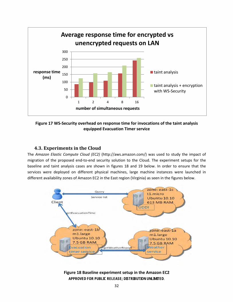
Figure 17 below shows the overhead caused by using WS-Security encryption with taint analysis as opposed to using unencrypted data with taint analysis. In these experiments, all data communication between the client and the Evacuation Timer service, between the Evacuation Timer service and the Weather service, and between the Trust Broker service and the taint analysis module is encrypted with symmetric keys in compliance with WS-Security. The results suggest a difference of around 50 milliseconds in the response time, which is negligible overhead in most cases.
0
100
200
300
400
500
600
1 2 4 8 16
response time (ms)
number of simultaneous requests
Average response time for the first 400 requests on LAN
baseline
taint analysis
APPROVED FOR PUBLIC RELEASE; DISTRIBUTION UNLIMITED.
32
Figure 17 WS-Security overhead on response time for invocations of the taint analysis equipped Evacuation Timer service
4.3. Experiments in the Cloud The Amazon Elastic Compute Cloud (EC2) (http://aws.amazon.com/) was used to study the impact of migration of the proposed end-to-end security solution to the Cloud. The experiment setups for the baseline and taint analysis cases are shown in figures 18 and 19 below. In order to ensure that the services were deployed on different physical machines, large machine instances were launched in different availability zones of Amazon EC2 in the East region (Virginia) as seen in the figures below.
Figure 18 Baseline experiment setup in the Amazon EC2
0
50
100
150
200
250
300
1 2 4 8 16
response time (ms)
number of simultaneous requests
Average response time for encrypted vs unencrypted requests on LAN
taint analysis
taint analysis + encryption with WS-Security

APPROVED FOR PUBLIC RELEASE; DISTRIBUTION UNLIMITED.
33
Figure 19 Taint analysis experiment setup in the Amazon EC2
Figure 20 below reports the average response times for the first 400 requests to the Evacuation Timer service for the baseline and taint analysis cases. As seen in the graph, the response times are still very close for up to 4 simultaneous requests. The overhead is somewhat larger, but still acceptable for 8 and 16 simultaneous requests. Experiments conducted in the Cloud were observed to have more varying results due to more uncontrolled conditions such as availability of bandwidth and other resources as the same physical machine can be shared by multiple virtual machines.
Figure 20 Response time vs number of simultaneous requests for the first 400 service invocations in the Amazon EC2
0
100
200
300
400
500
600
1 2 4 8 16
response time (ms)
number of simultaneous requests
Average response time for the first 400 requests in EC2
baseline
taint analysis

APPROVED FOR PUBLIC RELEASE; DISTRIBUTION UNLIMITED.
34
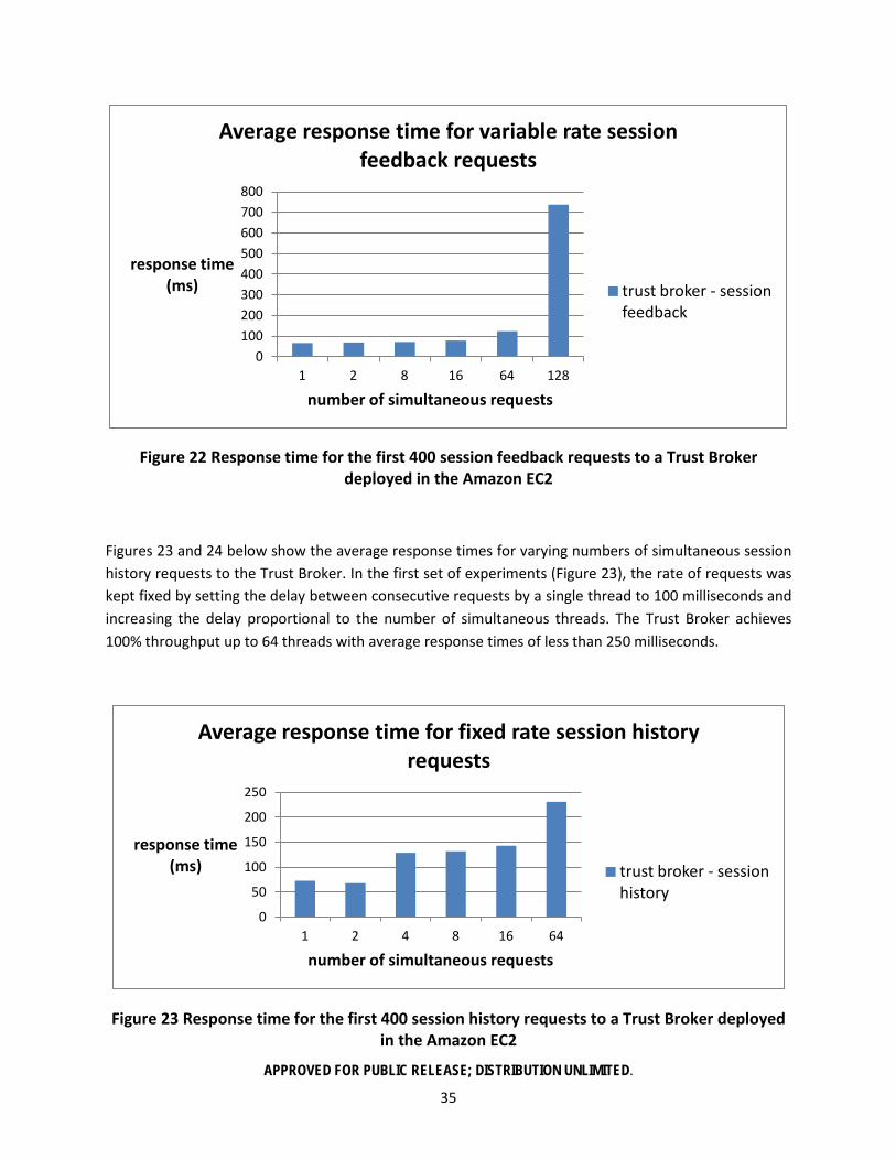
We also conducted experiments to measure the performance of the trust broker under increasing loads for the session feedback and session history methods. A large machine instance in the Amazon EC2 East region (east-1a availability zone) was used to host the trust broker for these experiments and all data communication between the trust broker and the client sending the requests was encrypted using symmetric keys in compliance with the WS-Security standard. Figures 21 and 22 below show the average response times (of the first 400 requests) for varying numbers of simultaneous session feedback requests to the trust broker. In the first set of experiments (Figure 21), the rate of requests was kept fixed by setting the delay between consecutive requests by a single thread to 100 milliseconds and increasing the delay proportional to the number of simultaneous threads. The results for these experiments show that the Trust Broker is able to handle 64 simultaneous requests in around 150 milliseconds and 128 requests in around 200 milliseconds and the increase in response time for increasing number of threads generally follows a logarithmic trend despite the overhead from WS-Security based encryption.
Figure 21 Response time for fixed rate session feedback requests to a Trust Broker deployed in the Amazon EC2
In the second set of experiments (Figure 22), bursts of requests were sent at increasing rates, i.e. the delay between the consecutive requests of all client threads was set to 100 milliseconds. The results of these experiments show that the increase in the rate of requests causes a small overhead in the response time up to 64 client threads; however there is a big jump in the overhead after 128 client threads, at which point load balancing should be considered.
0
50
100
150
200
250
1 2 8 16 64 128
response time (ms)
number of simultaneous requests
Average response time for fixed rate session feedback requests
trust broker - session feedback
APPROVED FOR PUBLIC RELEASE; DISTRIBUTION UNLIMITED.
35
Figure 22 Response time for the first 400 session feedback requests to a Trust Broker deployed in the Amazon EC2
Figures 23 and 24 below show the average response times for varying numbers of simultaneous session history requests to the Trust Broker. In the first set of experiments (Figure 23), the rate of requests was kept fixed by setting the delay between consecutive requests by a single thread to 100 milliseconds and increasing the delay proportional to the number of simultaneous threads. The Trust Broker achieves 100% throughput up to 64 threads with average response times of less than 250 milliseconds.
Figure 23 Response time for the first 400 session history requests to a Trust Broker deployed in the Amazon EC2
0 100 200 300 400 500 600 700 800
1 2 8 16 64 128
response time (ms)
number of simultaneous requests
Average response time for variable rate session feedback requests
trust broker - session feedback
0
50
100
150
200
250
1 2 4 8 16 64
response time (ms)
number of simultaneous requests
Average response time for fixed rate session history requests
trust broker - session history

APPROVED FOR PUBLIC RELEASE; DISTRIBUTION UNLIMITED.
36
In the second set of experiments (Figure 24), bursts of requests were sent at increasing rates, i.e. the delay between the consecutive requests of all client threads was set to 100 milliseconds. In these experiments the Trust Broker achieved 100% throughput up to 32 threads with average response times of less than 300 milliseconds. The response rate was observed to drop below 100% for 64 or more client threads, which requires load balancing.
Figure 24 Response time for the first 300 session history requests to a Trust Broker deployed in the Amazon EC2
0
50
100
150
200
250
300
350
1 2 4 8 16 32
response time (ms)
number of simultaneous requests
Average response time for variable rate session history requests
trust broker - session history

APPROVED FOR PUBLIC RELEASE; DISTRIBUTION UNLIMITED.
37
5. Conclusions
In this project we proposed an end-to-end security solution for SOA, which is based on the introduction of two new security components, i.e. the “Taint Analysis” module and the “Trust Broker” service. By providing the ability to track external service invocations in the completion of a service request and maintaining dynamic trust values for services, the proposed architecture allows clients to be informed about the full chain of service invocations in a request and possible misbehavior by services involved in the request. This architecture both makes it possible to judge the quality of the response received by the client (i.e. judge the possibility of a tainted response) and increase the chances of selecting trustworthy services using the reputation based system. Although the security architecture described above seems to take more of a retroactive approach for external service calls, it can easily be converted into a proactive one by either the prevention of external service calls to untrusted services by the TA or by requiring services in an invocation chain to contact the TB to get confirmation for the next service they will invoke. The latter approach will introduce additional delays in the response for the clients, but may be preferred for preventive security.
The proposed end-to-end security architecture is fully compatible with common Web services standards (WS*), as the services and data communication protocol are not affected by the security related modifications (i.e. additions) in the general SOA structure. The minimal set of WS* standards necessary to overcome the security challenges along with the proposed security components TA and TB were identified as WS-Security to ensure client and service authenticity as well as message level security through encryption and signing; and WS-Trust for the generation of security tokens required for authentication. By securing the communication between the TA modules and the TB using WS-Security, the proposed system ensures authenticity of session feedbacks, hence preventing unfair increase/decrease of trust values of services due to targeted feedback from malicious parties.
Experiments performed in the local area network as well as the Amazon Cloud (EC2) suggest that the proposed solution causes negligible overhead in terms of the service response time up to a certain load on the server, at which point load distribution should be considered. The same argument holds for the Trust Broker service as well; i.e. to avoid being a single point of failure prone to denial of service attacks, the TB should distribute its load over multiple servers. This makes the Cloud the best option for hosting the TB service. With elastic load balancing achieved by on-the-fly allocation of resources and creation/tear-down of virtual machines, a TB service in the Cloud will be able to meet the demands for different service request loads and prevent waste of resources in the case of decreased service traffic. Deploying services in the Cloud (in the case of using unreserved physical machines) brings up the question of multi-tenancy, which is a potential security threat. The proposed architecture partly mitigates the threats posed by multi-tenancy too, as in the case of a certified service being under attack, the TA module deployed on the server will report malicious behavior to the TB. Even in the case of a TA module under attack, it will be possible to detect that attack with a slight modification in the architecture. For that, the TB would need to wait on feedback from the TA module of every certified service, which is known to be invoked by a previous service and update the session history for that service call with a warning after a timeout period during which no feedback is received.

APPROVED FOR PUBLIC RELEASE; DISTRIBUTION UNLIMITED.
38
6. References
[ASP1] AspectJ Framework, http://www.eclipse.org/aspectj/
[BAA1] https://www.fbo.gov/index?s=opportunity&mode=form&tab=core&id= 9c3333a8b3ee0f6d136e1dc6606ef0df&_cview=0
[BFG05] K. Bhargavan, C. Fournet, A. D. Gordon, and G. O’Shea. An advisor for web services security policies. in SWS ’05: Proceedings of the 2005 workshop on Secure web services. New York, NY, USA: ACM Press, 2005, pp. 1–9.
[CAC1] http://en.wikipedia.org/wiki/Common_Access_Card
[CAC2] http://www.actividentity.com/products/securityclients/ActivClientforCommonAccessCards/
[CAC3] http://koji.fedoraproject.org/koji/packageinfo?packageID=5
[CAC4] https://help.ubuntu.com/community/CommonAccessCard
[CAC5] https://www.txsystems.com/scm-drivers/
[CAC6] http://www.militarycac.com/linux.htm
[CAC7] http://zxq9.com/dodcac/U10.4-LTS-32/Ubuntu10.4-LTS-32.html
[CAC8] http://dodpki.c3pki.chamb.disa.mil/rootca.html
[CAC9] http://koji.fedoraproject.org/koji/packageinfo?packageID=5
[CAC10 ] http://judsonsnotes.com/notes/index.php?option=com_content&view=article&id=349: cac-in-linux&catid=37:tech-notes&Itemid=59
[CDK02] F. Curbera, M. Duftler, R. Khalaf, W. Nagy, N. Mukhi. S. Weerawarana. Unraveling the Web services Web: an introduction to SOAP, WSDL, and UDDI. IEEE Internet Computing, (2002 (Mar./Apr.)), pp. 86–93.
[KBC07] M. Krohn, A. Yip, M. Brodsky, N. Cliffer, M. F. Kaashoek, E. Kohler, and R. Morris. Information flow control for standard OS abstractions. In Proc. of the 21st SOSP, Stevenson, WA, October 2007.
[JBO1] JBoss ESB, http://www.jboss.org/jbossesb/
[JBO2]JBoss AOP framework, http://www.jboss.org/jbossaop
[KEY1] http://download.oracle.com/javase/1.3/docs/tooldocs/win32/keytool.html
[KHH01] G. Kiczales, E. Hilsdale, J. Hugunin, M. Kersten, J. Palm. W. C. Griswold. Getting Started with
AspectJ. CACM 44(10): 59–65, October 2001.
[KLM97] G. Kiczales, J. Lamping, A. Mendhekar, et al. Aspect-Oriented Programming. Proceedings of the European Conference on Object-Oriented Programming (ECOOP). Springer-Verlag, Finland, 1997.
[PKI1] http://download.oracle.com/javase/1.5.0/docs/guide/security/p11guide.html
[PKI2] http://download.oracle.com/javase/1.5.0/docs/api/javax/security/cert/ X509Certificate.html
APPROVED FOR PUBLIC RELEASE; DISTRIBUTION UNLIMITED.
39
[PKI3] http://download.oracle.com/javase/1.4.2/docs/guide/security/CryptoSpec.html
[PKI4] http://www.developer.com/java/other/article.php/3587361/Java-Applet-for-Signing-with-a-Smart-Card.htm
[PKI5] http://mywiki.ncsa.uiuc.edu/wiki/Java_PKCS11
[PKI6] http://java.sun.com/developer/technicalArticles/J2SE/security/
[PKI7] http://www.mayrhofer.eu.org/create-x509-certs-in-java
[SPR1] AOP in Spring Framework, http://static.springsource.org/spring/docs/2.0.x/reference/aop.html
[WST1] http://en.wikipedia.org/wiki/WS-Trust
[WST2] http://www.ibm.com/developerworks/library/specification/ws-trust/
[WST3] http://community.jboss.org/wiki/PicketLinkSecurityTokenService
[WST4] http://community.jboss.org/wiki/PicketLinkSecurityTokenService
[WSS1] http://en.wikipedia.org/wiki/WS-Security
[WSS2] http://msdn.microsoft.com/en-us/library/ms977327.aspx
[WSS3] http://community.jboss.org/wiki/JBossWS-StackCXFUserGuide#WSSecurity
[WSP] http://www.w3.org/Submission/WS-Policy/#Introduction
[VEK07] S. VanDeBogart, P. Efstathopoulos, E. Kohler, M. Krohn, C. Frey, D. Ziegler, F. Kaashoek, R. Morris, and D. Mazi`eres. “Labels and event processes in the Asbestos operating system”, ACM TOCS, 25(4):11:1–43, December 2007.
[ZBK06] N. Zeldovich, S. Boyd-Wickizer, E. Kohler, and D. Mazi`eres. Making information flow explicit in HiStar. In Proc. of the 7th OSDI, pages 263–278, Seattle, WA, November 2006.
[ZBM08] N. Zeldovich, S. Boyd-Wickizer, and D. Mazi`eres. Securing distributed systems with information flow control. In NSDI, 2008.

APPROVED FOR PUBLIC RELEASE; DISTRIBUTION UNLIMITED.
40
Appendix
A-1 Schedule and Timeline

APPROVED FOR PUBLIC RELEASE; DISTRIBUTION UNLIMITED.
41
A-2 Publications
• N. Idika, B. Bhargava. A Kolmogorov. Complexity Approach for Measuring Attack Path Complexity, in Proceedings of IFIP International Information Security (SEC 2011) conference, June 2011, Lucerne, Switzerland.
• P. Angin, B. Bhargava, R. Ranchal, N. Singh, L. Lilien, L. Othmane, M. Linderman. A User-Centric Approach for Privacy and Identity Management in Cloud Computing, in Proceedings of 29th IEEE Symposium on Reliable Distributed System (SRDS), Nov 2010, New Delhi, India.
• R. Ranchal, B. Bhargava, L. Othmane, L. Lilien, A. Kim, M. Kang, M. Linderman. Protection of Identity Information in Cloud Computing without Trusted Third Party, in Proceedings of Third International Workshop on Dependable Network Computing and Mobile Systems (DNCMS 2010) in conjunction with 29th IEEE Symposium on Reliable Distributed System (SRDS), Oct 2010, New Delhi, India.
• B. Bhargava, N. Singh, A. Sinclair. Privacy and Security in Cloud Computing through Identity Management: Microsoft Cardspace, in Proceedings of the International Conference on Advances in Computing and Communication, 2011, Hamirpur, India.
• T. Bao, Y. Zheng, Z. Lin, X. Zhang and D. Xu. Strict Control Dependence and Its Effect on Dynamic Information Flow Analyses, International Symposium on Software Testing and Analysis, Trento, Italy, 2010.
• Z. Lin, X. Zhang, and D. Xu. Convicting Remote Exploitable Vulnerabilities: An Efficient Input Provenance Based Approach, Proceedings of IEEE/IFIP International Conference on Dependable Systems and Networks, 2008
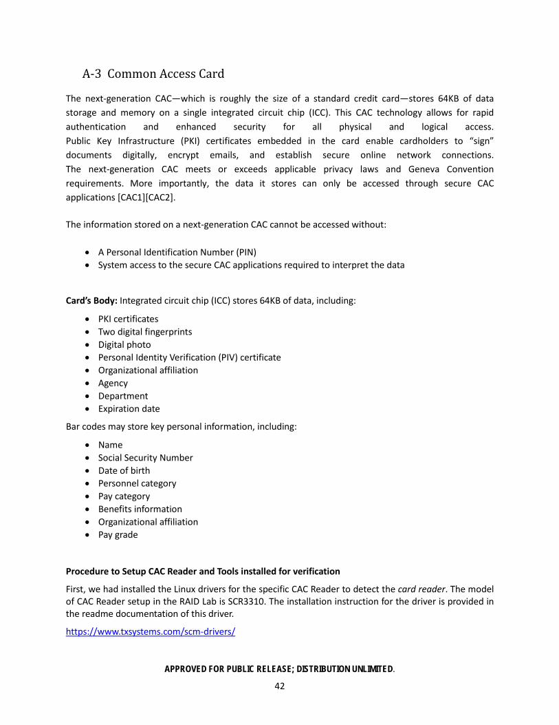
APPROVED FOR PUBLIC RELEASE; DISTRIBUTION UNLIMITED.
42
A-3 Common Access Card
The next-generation CAC—which is roughly the size of a standard credit card—stores 64KB of data storage and memory on a single integrated circuit chip (ICC). This CAC technology allows for rapid authentication and enhanced security for all physical and logical access. Public Key Infrastructure (PKI) certificates embedded in the card enable cardholders to “sign” documents digitally, encrypt emails, and establish secure online network connections. The next-generation CAC meets or exceeds applicable privacy laws and Geneva Convention requirements. More importantly, the data it stores can only be accessed through secure CAC applications [CAC1][CAC2].
The information stored on a next-generation CAC cannot be accessed without:
• A Personal Identification Number (PIN) • System access to the secure CAC applications required to interpret the data
Card’s Body: Integrated circuit chip (ICC) stores 64KB of data, including:
• PKI certificates • Two digital fingerprints • Digital photo • Personal Identity Verification (PIV) certificate • Organizational affiliation • Agency • Department • Expiration date
Bar codes may store key personal information, including:
• Name • Social Security Number • Date of birth • Personnel category • Pay category • Benefits information • Organizational affiliation • Pay grade
Procedure to Setup CAC Reader and Tools installed for verification
First, we had installed the Linux drivers for the specific CAC Reader to detect the card reader. The model of CAC Reader setup in the RAID Lab is SCR3310. The installation instruction for the driver is provided in the readme documentation of this driver.
https://www.txsystems.com/scm-drivers/
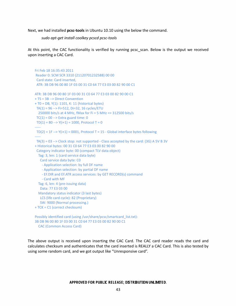
APPROVED FOR PUBLIC RELEASE; DISTRIBUTION UNLIMITED.
43
Next, we had installed pcsc-tools in Ubuntu 10.10 using the below the command.
sudo apt-get install coolkey pcscd pcsc-tools
At this point, the CAC functionality is verified by running pcsc_scan. Below is the output we received upon inserting a CAC Card.
Fri Feb 18 16:35:43 2011 Reader 0: SCM SCR 3310 (21120701232588) 00 00 Card state: Card inserted, ATR: 3B DB 96 00 80 1F 03 00 31 C0 64 77 E3 03 00 82 90 00 C1 ATR: 3B DB 96 00 80 1F 03 00 31 C0 64 77 E3 03 00 82 90 00 C1 + TS = 3B --> Direct Convention + T0 = DB, Y(1): 1101, K: 11 (historical bytes) TA(1) = 96 --> Fi=512, Di=32, 16 cycles/ETU 250000 bits/s at 4 MHz, fMax for Fi = 5 MHz => 312500 bits/s TC(1) = 00 --> Extra guard time: 0 TD(1) = 80 --> Y(i+1) = 1000, Protocol T = 0 ----- TD(2) = 1F --> Y(i+1) = 0001, Protocol T = 15 - Global interface bytes following ----- TA(3) = 03 --> Clock stop: not supported - Class accepted by the card: (3G) A 5V B 3V + Historical bytes: 00 31 C0 64 77 E3 03 00 82 90 00 Category indicator byte: 00 (compact TLV data object) Tag: 3, len: 1 (card service data byte) Card service data byte: C0 - Application selection: by full DF name - Application selection: by partial DF name - EF.DIR and EF.ATR access services: by GET RECORD(s) command - Card with MF Tag: 6, len: 4 (pre-issuing data) Data: 77 E3 03 00 Mandatory status indicator (3 last bytes) LCS (life card cycle): 82 (Proprietary) SW: 9000 (Normal processing.) + TCK = C1 (correct checksum) Possibly identified card (using /usr/share/pcsc/smartcard_list.txt): 3B DB 96 00 80 1F 03 00 31 C0 64 77 E3 03 00 82 90 00 C1 CAC (Common Access Card)
The above output is received upon inserting the CAC Card. The CAC card reader reads the card and calculates checksum and authenticates that the card inserted is REALLY a CAC Card. This is also tested by using some random card, and we got output like “Unresponsive card”.

APPROVED FOR PUBLIC RELEASE; DISTRIBUTION UNLIMITED.
44
Installation of CoolKey – A PKCS#11 Module
The list of steps needed to install the coolkey in Ubuntu 10.10 are as follow: )Note that coolkey does not work in Ubuntu 10.04.)
1. wget http://kojipkgs.fedoraproject.org/packages/coolkey/1.1.0/17.fc15/i686/coolkey-1.1.0-17.fc15.i686.rpm (or a later version, if available)
2. sudo apt-get install rpm2cpio
3. rpm2cpio coolkey-1.1.0-17.fc15.i686.rpm | sudo cpio -idmv
4. sudo rsync -va ./usr/lib/ /usr/lib/
The coolkey download is available online [CAC3].
Downloading the DoD Root CA certificates, and other intermediate certificate
Below is the link used to download the DoD Root CA certificates. The procedure to install these certificates is given in the link. Install all the certificates provided in the link.
http://dodpki.c3pki.chamb.disa.mil/rootca.html
Linking the CAC Reader to Coolkey in Firefox
Client Certificate Setup:
1. Insert CAC into reader - the green light should flash. 2. Add CAC Module to Firefox as a Security Device
A. Preferences Menu
B. Advanced Section
C. Encryption Tab
D. Security Devices Button
E. Load Button
F. Enter CAC Module as the module name, and browse to /usr/lib/pkcs11/libcoolkeypk11.so for the module filename.
After this, upon visiting a military DoD site (HTTPS), it automatically authenticates the CAC card holder, and the person requires to enter a secret PIN to access the website.
We used [CAC4-10] to setup this configuration.
PKI authentication and retrieval of security information from the card
The CAC Card authentication uses PKI authentication mode. The CAC Card consists of all the user specific information along with a private key encoded in the chip. The DoD certificates are X.509 certificates which acts as a container for public key. The public key is certified by a Certification Authority and is registered using a Registration Authority. A PKCS#11 Module is required for performing a PKI authentication, by retrieving the details from the CAC card and the public key from the X.509 certificate.
APPROVED FOR PUBLIC RELEASE; DISTRIBUTION UNLIMITED.
45
Sun provides a PKCS#11 provider for accessing the information in the card. Hence Sun Java is required. Below is the link (PKCS#11 Reference Guide) that defines all functionalities for the PKCS#11 provider [PKI1].
Sun provides javax.security.cert.X509Certificate class for accessing the X.509 container and to perform various operations on it. Below is the link that defines all library functions in that class [PKI2-3].
Setting up Sun-Java in the System for the use of Sun PKCS#11 Provider in Java
The Openjdk cannot be used since configuration requires to be done in the java.security file at /<JAVA_HOME>/lib/security. These files are specific to Sun Java.
Below is the installation procedure followed to setup Sun Java.
1. sudo add-apt-repository "deb http://archive.canonical.com/ lucid partner"
2. sudo apt-get update
3. sudo apt-get install sun-java6-jre sun-java6-plugin
To make Sun Java as the default Java for execution,
sudo update-java-alternatives -s java-6-sun
(or) sudo update-alternatives --config java and select interactively
Functionality
A Java program that uses SUN JDK has been written to perform PKI authentication. The code has the PKCS#11 library path and the Smart Card PIN hardcoded in the program. On using the PIN and the library, the private key and the X.509 certificate chain are extracted from the smart card. The PKI authentication is performed using the private key and X.509 certificates extracted from the card with the public key. Once authenticated, the X.509 certificate chain is placed as ASN.1 DER encoded sequence of bytes, additionally encoded in Base64. This encoded Base64 X.509 certificate chain will be added to the WS-Security header tag in the SOAP envelope.
Since a Common Access Card is not provided to test the code, the authenticated could not be performed. Instead, assuming PKI authentication has happened, we use the Base64 encoded X.509 certificate chain in the SOAP header as the start point. The above stated limitation has led into creating of dummy X.509 certificates for Base64 encoding and using as the security token in the SOAP message [PKI14-16].
Creating X.509 certificates
In [PKI17] the details of creation of a dummy X.509 certificate in Java is provided. Ideas can be drawn from the link, and can be Base64 encoded, to be added to the SOAP envelope header.
Keytool :
Keytool manages a keystore of private keys and their associated X.509 certificate chains authenticating the corresponding public keys. Keytool can also be used in the creation of X.509 certificate chains [KEY1].