steel co(umns of rolled wide flange section
TRANSCRIPT
STEEL CO(UMNS OF
ROLLED WIDE FLANGE SECTION
fRITZ ENGmEERn~G LABOl\ATOHY. LEHIGH UNIVERSITY
''''J3ETHLEHE~ PENNSYLVANIA
189,,4
PROGRESS REPORT NO.1. '
BY BRUCE JOHNSTON AND LLOYD CHENEY,/
AM E R I CAN . INSTIT UTE 0 F STEE L CON ST R U C T ION
COLUMN RESEARCH AT LEH I G H UNIVERSITY
COMMITTEE ON TECHNICAL RESEARCH
AMERICAN INSTITUTE OF' STEEL CONSTRUCTION
"
STEEL COLUMNS OF
ROLLED WIDE FLANGE SECTION
PROGRESS REPORT NO.1
BY BRUCE JOHNSTON AND LLOYD CHENEY
AMERICAN INSTITUTE OF STEEL CONSTRUCTION
C'OLUMN RESEARCH AT LEHIGH UNIVERSITY
COMMITTEE ON TECHNICAL RESEARCH
AMERICAN INSTITUTE OF" STEEL CONSTRUCTION
NOVEMBER,1942
CONTENTS
Page
FOREWORD. . . . . . . . . . . . . .. . . . . . . . . .. 4
GENERAL '.' . . . . . . . .. 5
REVIEW OF COLUMN TESTS 7
COMPRESSIVJ<J STRENGTHS OF COLUMN FLANGES OF "VIDE
FLANGE SJ<JCTION . . . . . . . . . . . . . . . 10
EFFECT OF BEAM CONNECTIONS ON LOCAL COMPRESSInJ
STRENGTH OF COLUMN FLANGE . . . . . . 26
SUMMARY AND CONCLUSIONS
LIST OF RJ<JFERENCES
[3 ]
36
:37

FOREWORD
DURING the spring of 1938, the Committee on Technical H.esearchof the American Institute of Steel Construction decideel to initiate
a program of tests in oreler to obtain answers to several·moot pointsthat existed in regarel to the behavior of wiele flange column sectionswith respect to (a) the compressive strength of flanges, and (b) the
, behavior 9f wide flange columns uneler eccentric loading.
A program of tests was aceordingly established at the Fritz EngineeringLaboratory of Lehigh University and work commenced in September,1938.
The results of the investigation on the local compressive strength ofwide flange columns are pr(;lsented in the accompanying Progress ReportNo. ], by Dr. Bruce Johnston, Associate Director, Fritz EngineeringLaboratory, Lehigh University, anel Mr. Lloyd Cheney, A. 1. S. C.Research Fellow, Lehigh University.
COMMITTEE ON TECHNICAL RESEARCH
AMERICAN INSTITUTE OF STEEL
CONSTRUCTION
F. H. FRANKLAND, Cha'i1'lIwn
C. A. AOAMS .
H. D. HUSSEY.
JONATHAN JON~;S
J. R. LAMBJm'l'.
L. S. MOIss~;rFF .
W AI/rim WEISKOPF
NEW YORK, N. Y.NOVEMBER, 1942
American Institute of Steel Construction
. Consulting Engineer, Philadelphia, Pa.
American Bridge Company, New York, N. Y.
Bethlehem Steel Company, Bethlehem, Pa.
The Phoenix Bridge Company, Phoenixville, Pa.
Consulting Engineer, New York, N. Y.
Consulting Engineer, New York, N. Y.
[41
1PROGRESS REPORT
STEEL COLUMNS
ROLLED WI DE FLANGE
NO. 1
OF
SECT I ON
AMERICAN INSTITUTE OF STEEL CONSTRUCTION
COLUMN RESEARCH AT LEHIGH UNIVERSITY
BY BRUCE JOHNSTON* AND LLOYD CHENEYt
This progress report will serve as a general introduction to theprogram of column tests sponsored by the American Institute of SteelConstruction at the Fritz Engineering LaboratQry of Lehigh Universitybetween September 1938 and June 1942.
This report will also present test results on the local compressivestrength of the column flanges. Theoretical analyses, in general, willnot be made, as the literature provides extensive references on thissubject. Moreover, the elastic buckling phenomena usually treated bymathematical analyses are primarily valid outside the range of usualapplication of the rolled structural steel wide flange column section.
The list of references appended to this Progress Report No. 1 willalso be referred to'in later progress reports. This list of references makesno pretense at completeness. Salmon, in his book on columns l1**,publisheJi in 1920, lists 375 references to previous analytical and experimental works on this subject. More recently, in 1940, Moisseiff andLi.enhard18 review the subject of "Elastic Stability applied to StructuralDesign" and list 52 references, mostly from German sources, and mostlyon work published since 1920. The references listed at the end of thisreport have been selected for their availability and are all in English,but do not necessarily represent the original work on any particularsubject. "Theory of Elastic· Stability" by S. Timoshenko12 , togetherwith the references just cited, furnish a very adequate bibliography onthe subject of columns.
The American Institute of S~eel Construction program of tests atLehigh University may be divided into the following parts:
(1) Local compressive strength tests of flanges of wide flangecolumns, reported herein.
* Associate Direct.or, Fritz Laboratory, and Associate Professor of Civil Engineering, LehighUniversity. (Absent on leave.)
t Instructor of Applied Mechanics, Case School of Applied Science, Cleveland, Ohio,Formerly A. I. S. C. Research Fellow, Lehigh University.
** Numerals refer to references listed at the end of this report.
[ 5]
6 WIDE FLANGE STEEL COLUMNS
(2) 'l\ests of eccentrically loaded columns, reported in ProgressReport No.2.
(3) Tests of columns as part of frames, now in progress.(4) Tests of stiffened plates in compression, now in progress.Preliminary progress reports have been circulated previously in
mimeographed form l• 2. These reports have been studied by the Ameri
can Society of Civil Engineers Committee on Design of StructuralMembers as well as by the Committee on Technical Research of theA.I.S.C., by whose permission the two committees are cooperating onthe general subject of column research. All of the Fritz LaboratoryStaff have contributed to the program. Professor Hale Sutherland isDirector of the Laboratory and Mr. Howard Godfrey was Engineer ofTests when most of the tests were made. Mr. Robert Mains, presentEngineer of Tests, and Mr. George Packer, A.I.S.C. R;esearch Fc;llow,
'assisted in the preparation of this report
PROGRESS REPORT NUMBER ONE
GENERAL REVIEW OF COLUMN TESTS AND SUMMARY OF
FACTORS AFFECTING COLUMN STRENGTH
This section is in large part abstracted from the First.ProgressReportof the A.S.C.E. Committee on "Design of Structural Members"6*.
Extensive work on column tests was carried on by two A.S.C.E.Committees. The first of these was the Special Committee of the Boardof Dir'ection on Steel Columns and Struts, organized in January 1909,and whose work was terminated in 1918. Special reference is made to the"General Programrr.e for Colu,mn Tests" in a closing discussion of thiscommittee's final report7. This program, with minor modifications,might well serve today as a guide on the question of further columnresearch. As. a matter of fact, the .work now in progress or recentlycompleted fits into the program very well.
In 1923 another A.S.C.E. committee, the "Special Committee of theBoard of Direction on Steel Column Research" was formed. It submitted three reports 8 •9 ,lO and finished its work in 1933. These reportscover a very complete and detailed review of previous column teststogether with results of many new tests made for the committee
Other important sources of information ll ,12,13 include references tomost of the work done on columns during the past two hundred years.
A summary of the factors that affect the strength of a column willprovide the basis for understanding the general problem. These factorsmay be defined by the way they affect the strength of an "idealized"column. An "idealized" column wiII be defined as one that is made ofa perfectly elastic material, is loaded axially through frictionless pinsat each end, is perfectly straight, and does not fail locally. This .idealizedcolumn will buckle elastically at the "Euler" critical load.
.".'EIPcr = ---
, I'in which: E = Young's Modulus,
I = Moment of Inertia,l = Length of Column.
The idealized column is usually quite different from. the actualcolumn as constructed and used in a structure. In the actual columnthe strength of the column is different from that given by the Eulerformula because of: (1) the non-linear shape of the stress-strain relation,(2) accidental imperfections, (3) the known end eccentricity, (4) theshape of the cross section, (5) the torsional behavior, (6) shearing
• These numbers refer to references list'ed on pages 37 and 38, at the eno of th,s report.
8 WIDE FLANGE STEEL COLUMNS
deformation, (7) local buckling or crippling of a part of the column,(8) method of fabrication, and (9) continuity of action in a frame.
(1) Non-Linear Shape of Stress-Strain Relation-Above the proportional limit the relation between stress and strain is no longer definedby Young's elastic modulus. The strength of the column is reduced,and< may be determined approximately -by using a "reduced modulus", E R , in the "Euler" formula, Eq. (1)14. In the case of structural steelsthe yield point represents the practical upper limit of column strengthfor short columns which do not buckle elastically.
(2) Accidental Imperfections such as curvature, end eccentricity, nonhomogeneity, etc., act to reduce the strength.
(3) Known End Eccentricity-When the material has an elastic stressstrain relationship the maximum stress may be calculated by the"secant" or "eccentricity" formula. In the case of materials with awell-defined yield point, such as structural steel, the load at whichmaximum stress reaches the yield point may be divided by an arbitraryfactor of safety to indicate a safe design load. When the eccentricity isin the strong plane the possibility of lateral-torsional buckling shouldbe investigated3•
(4) Shape of Cross Section-The shape of the column cross sectionaffects the strength when considered in conjunction with a materialhaving a non-linear stress-strain relation14.
(5) Torsional Behavior-Certain shapes of thin materialmay buckleby twisting, under either axial or eccentric load3 , 15.
(6) Shearing Deformation~The theoretical strength of a column isreduced, especially in the case of the built-up column, when shearingdeformation is considered12 •
(7) Local Buckling or Crippling of a Part of the Column-Manydifferent cases are revievved by S. Timoshenko12 •
. (8) Method of Fabrication-A method of fabrication which introducesinitial stresses or causes warping of the component parts may reducethe strength of the column.
(9) Continuity of Action in a Frame-Compression in a strut reducesits bending stiffness, whereas tension increases the bending stiffness.Buckling of a member in a frame ensues when the summation of bending stiffness becomes equal to zero at any joint of a frame1
".
It is also important to emphasize that much of the knowledge ofcolumn beh:1Vior has been based on laboratory experiments in which
- the ends of the column are either milled flat, or simulate a pin end byuse of a knife edge or a roller nest. Actual columns usually have framed,end connections which are not equivalent to the end conditions in the
PROGRESS REPORT NUMBER ONE 9
usual laboratory test. In a laboratory test of an eccentrically loadedcolumn the eccentricity is usually maintained at a constant value up tofailure, but the equivalent eccentricity of load in a framed column variesas the load varies. For these and other reasons the difference betweenlaboratory tests and actual column behavior should always be kept inmind.
The multiplicity of factors affecting column strength has led tosome confusion of thought in dealing with the problem. It is obviouslyimpracticable to consider all factors at once in a design formula. Investigators frequently have considered only one or two of the factors andhave then magnified the factors considered to include arbitrarily all ofthe others. For example, in the case of non-ferrous alloys and some ofthe high-strength steels, the non-linear stress-strain relationship14 maywell be the most important factor affecting the strength of an axiallyloaded column. Imperfections of shape, curvature, and accidentaleccentricity may be covered approximately. by modifying the assumedstress-strain relationship. In the .case of structural steel, accidentaleccentricities and curvature may be the more important factors, and therelatively small variation from a linear stress-strain relation up to theyield point may be taken care of by modification of the eccentricity orsecant formula. Another investigator17 has proposed to take account ofall factors by assumed initial curvature of the column, which results informulas for maximum stress similar to the secant formula.
Mention should also be made of the paper by Leon S. Moisseiff andFrederick Lienhard18, which proposes rules of design for the plate elements in compression members. Another A.LS.C. research project atLehigh is devoted to questions raised by this paper. At the U. S. Bureauof Standards, still another A.LS.C. research project is being conducted
.to determine the compression strength of plates with various shapedholes.

10 WIDE FLANGE STEEL COLUMNS
(2)
COMPRESSIVE STRENGTH TESTS OF COLUMN FLANGESOF WIDE FLANGE SECTIONS
A column is usually made up of component parts which may beconsidered as plate elements. These plate elements may buckle locallyif their thickness is relatively small in comparison with the widthbetween ribs or between component parts of the column which hold theplate elements in line. Structural sections are usually proportioned sothat local buckling will not occur in the elastic range, in which case theplate elements will usually buckle "inelastically" or by "plastic buckling" at an average stress somewhere between the proportional limit andthe yield point of the material. In very compact sections buckling mayoccur at stresses above the yield point, but the yield point usuallyrepresents the practical upper limit of strength. Theoretical solutionsof elastic buckling have been maxie for various idealized edge or boundaryconditions. Many of these are presented in Timoshenko's work onElastic Stability12 and recent work in Germany is listed by Moisseiffand Lienhard's. The results of these analyses give a value for theaverage critical stress at which buckling will take place, i.e.
IT" } '7f2E (t)2'or = k -r
er12(1 - v') 'W
IT", r" = critical direct· or shear stress respectivplyk = constant which depends on proportions of the plate and boundary
conditionsE = Young's Modulusv = Poisson's Ratiot = thickness of plate element
10 = width of plate element
An approximation may be made when the critical buckling stress isin the inelastic range by substituting a reduced modulus Erin place ofE in Eq. (2). A conservative estimate of the reduced modulus may bemade by basing it on the slope of the tangent to the,stress-strain diagramat any particular point. However, the stress beyond the proportionallimit may not affect the plate in the same manner in every direction.Allowance is made for this hypothesis by some investigators. Moisseiffand Lienhard18 propose, for example, values of E r for silicon structuralsteel, structural steel, and structural aluminum alloy 27 ST, based on .records of column tests. Since all columns as well as plates are actuallysomewhat crooked, and rarely uniformly stressed at the ends, it followsthat the E r proposed by Moisseiff and Lienhard includes allowances for'such factors.
PROGRESS REPORT NUMBER ONE 11
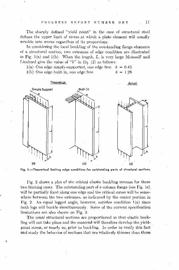
The sharply defined "yield point" in the case of structural steeldefines the upper limit of stress.at which a plate element will usuallywrinkle into waves regardless of its proportions.
In considering the local buckling of the outstanding flange elementsof a. structural section; two extremes of edge condition are illustratedin Fig. l(a) and l(b). When the length, L, is very large Moisseiff andLienhard give the value of "k" in Eq. (2) as follows:
l(a) One edge simply-supported, one edge free k = 0.43l(b) One edge built in, one edge free k = 1.28
Theoretical
...J
(a) (bl
...J
Fig. I.-Theoretical limiting .edge conditions Jor outstonding parts of structural sections.
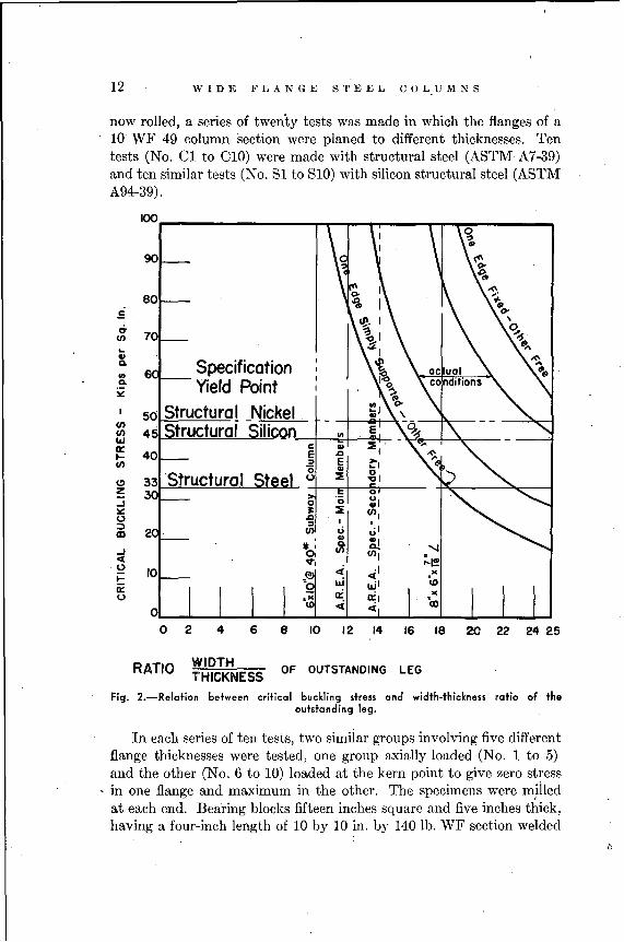
Fig. 2 shows a plot of the critical elastic buckling stresses for thesetwo limiting cases. The outstanding part of a column flange (see Fig. Ie).will be partially fixed along one edge and the critical stress will be somewhere between the two extremes, as indicated by the center portion inFig. 2. An equal legged angle, however, satisfies condition 1(a) sinceboth legs will buckle simultaneously. Some of the current specificationlimitations are also shown on Fig. 2.
The usual structural sections are proportioned so that elastic buckling will not take place and the material will therefore develop the yieldpoint stress, or nearly so, prior to buckling. In order to verify this factand study the behavior of sections that are relatively thinner than. those
12 WID E F I, A N G EST EEL C 0 LU M N S
now rolled, a series of twenty tests was made in which the flanges of a10 WF 49 column section ,,,ere planed to different thicknesses. Tentests (No. C1 toC10) were made with structural steel (A8TM A7-39)and ten similar tests (No. 81 to 810) with silicon structural steel (A8TMA94-39).
6 8 10 12 14 16 18 20 22 24 2540L.-....._ ......_..L.......J~-'-_......_..L.........L_.....L._...l...._l...-....l.....J
o 2
100
90 ~~
,0(\
80 ~....= ()o
\
0-70
q.(/) ~-.L.
..... ,0(\Q. Specification 10......Q. Yield Point~
I 50 Structural _Nickel(/) Structural i1iCQrl(/) 45 ellWa: .. '... 40 &J
(/) E..C) Structural :lzoJ 0 ·0~ ~ ~0 &J
I:;) ::>III (/) U..t: Q.
oJ 0, (/)
ex "',,0
i= 10 ,@
it:0
RATIO WIDTHTHICKNESS
OF OUTSTANDING LEG
Fig. 2.-Relation between critical buckling stress and width-thickness ratio of theoutstanding leg.
In each'series of ten tests, two simiiar groups involving five differentflange thicknesses were tested, one group axially loaded (No. 1 to 5)and the other (No.6 to 10) loaded at the kern point to give zero stress
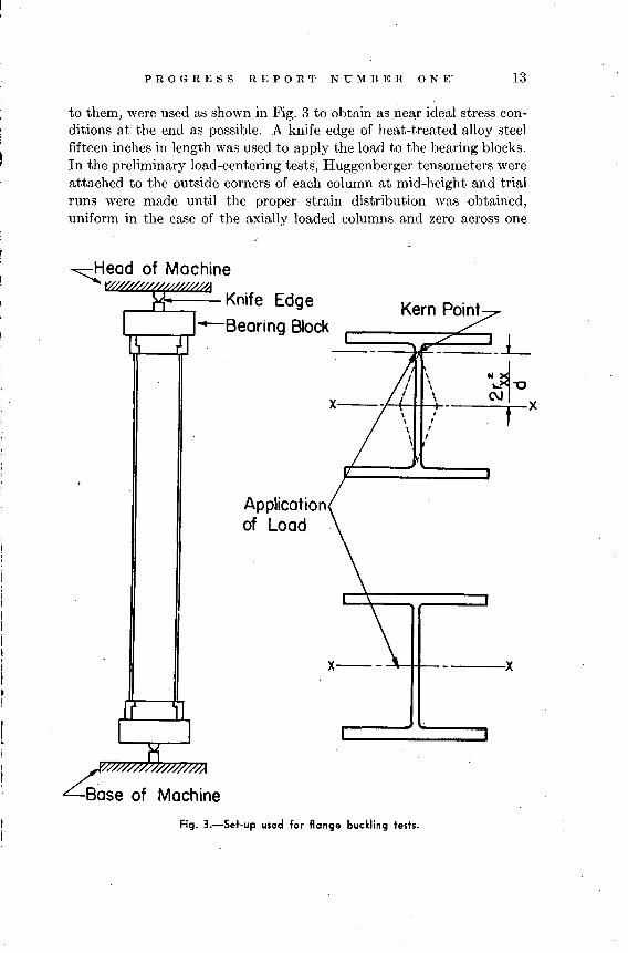
- in one flange and maximum in the other. The specimens were miiledat each end. Bearing blocks fifteen inches square and five inches thick,having a four-inch length of 10 by 10 in. by 140 lb. WF section welded
D
PRO G RES S REP 0 R T N U M B E RON E" 13
to them, were used as shown in Fig. 3 to obtain as near ideal stress conditions at the end as possible. A knife edge of heat-treated alloy steelfifteen inches in length was used to apply the load to the bearing blocks.In the preliminary load-centering tests, Huggenberger tensometers wereattached to the outside corners of each column at mid-height and trialruns were made until the proper strain distribution was obtained,uniform in the case of the axially loaded columns and zero across one
---.X
Kern Point
==:::;}~==_ L
\ ~~~x-·-- -f---<!-\-H-,+-' --.-'X
\ '\ I\
Applicationof Load
,.
I II I
I II I
M
~ead of Machine
Knife Edge-Bearing Block
4ase of Machine
,.I
Fig. 3.-Set.up used for flange buckling tests.
14 'WIDE FLANGE STEEL COLUMNS
flange in the case of the kern point loading. These load-centering runswere made in the elastic range and the desired results were obtainedwithin a tolerance of a few per cent. During the actual tests to failurethe' tensometers were replaced by four "compressometers" which measured the deformation at each corner OVEr a 46-in. gage length by meansof I/lOOO-in. dial gages attached to guided steel bars. This is shown inFig: 4, which is a picture of one of the specimens ready for test.
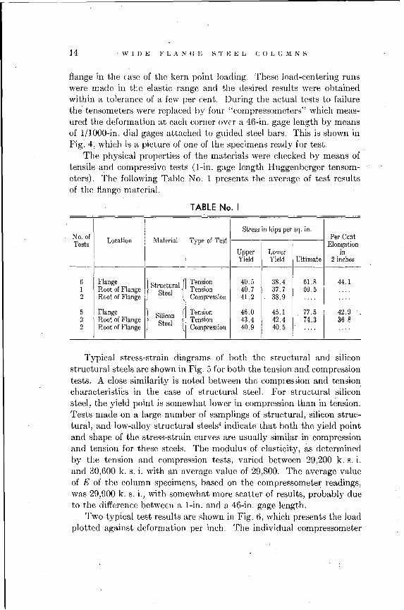
The physical properties of the materials were checked by means oftensile and compressive tests (I-in. gage length Huggenberger tensometers). The following Table No.1 presents the average of test resultsof the flange material.
TABLE No. II
I Type of TestIStress in kips per sq. in.
No. ofLocation Material Per Cent
Tests ElongationI Upper Lower in
Yield Yield Ultimate 2 inches
6 Flange} Structural {
Tension 40.5 38.4 61.8 44.11 Root of Flange
SteelTension 40.7 37.7 59.5 ....
2 Root of Flange Compression 41.2 38.9 .... ....
5 Flange } Silicon( Tension 46.0 45.1 77.5 42.9
2 Root of FlangeSteel t Tension 43.4 42.4 74.3 368
2 Root of Flange Compression 40.9 40.5 .... . ...
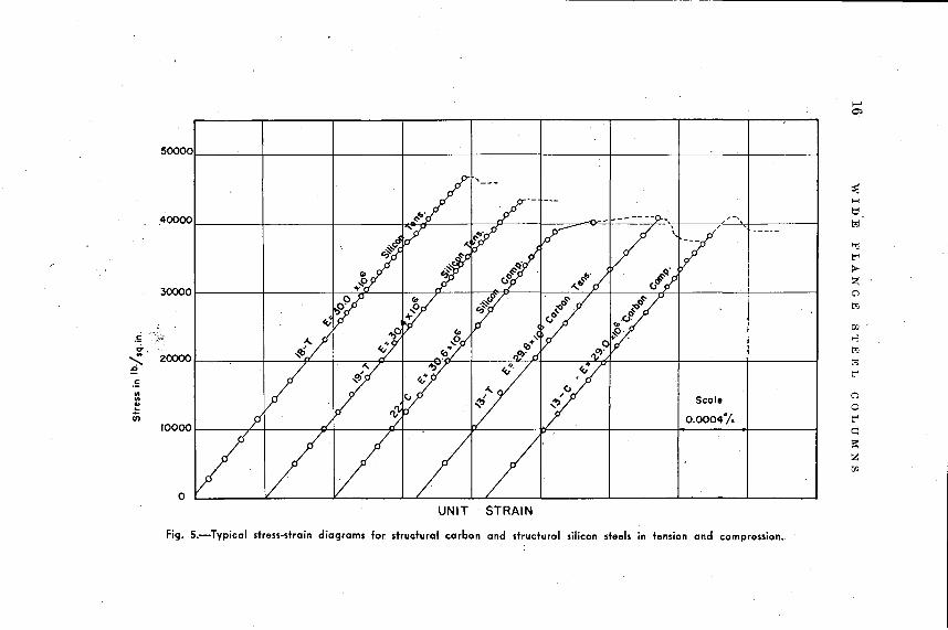
Typical stress-strain diagrams of both the structural and siliconstructural steels are shown in Fig. 5 for both the tension and compressiontests. A close similarity is noted between the compres3ion and tensioncharacteristics in the case of structural steel. For structural siliconsteel, the yield point is somewhat lower in compression than in tension.Tests made on a large number of samplings of structural, silicon structural, and 10w-alloJ~ structural steels4 indicate that both the yield pointand shape of the stress-strain curves are usually similar in compressionand tension for these steels. The modulus of elasticity, as determinedby the tension and compression tests, varied between 29,200 k. s. i.and 30,600 k. s. i. with an average value of 29,800. The average valueof E of the column specimens, based on the compressometer readings,was 29,900 k. s. i., with somewhat more scatter of results, probably dueto the difference between a I-in. and a 46-in. gage length.
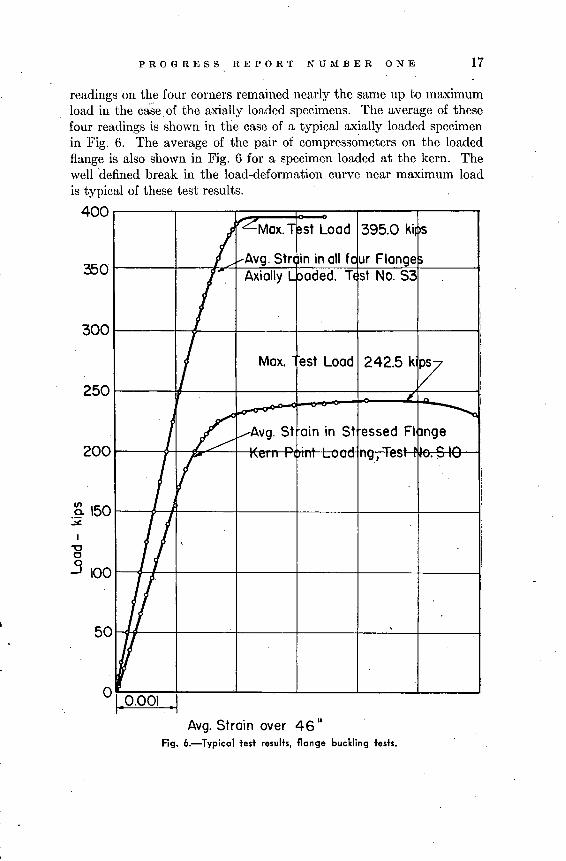
Two typical test results are shown in Fig. 6, which presents the loadplotted against deformation per inch. The individual compressometer
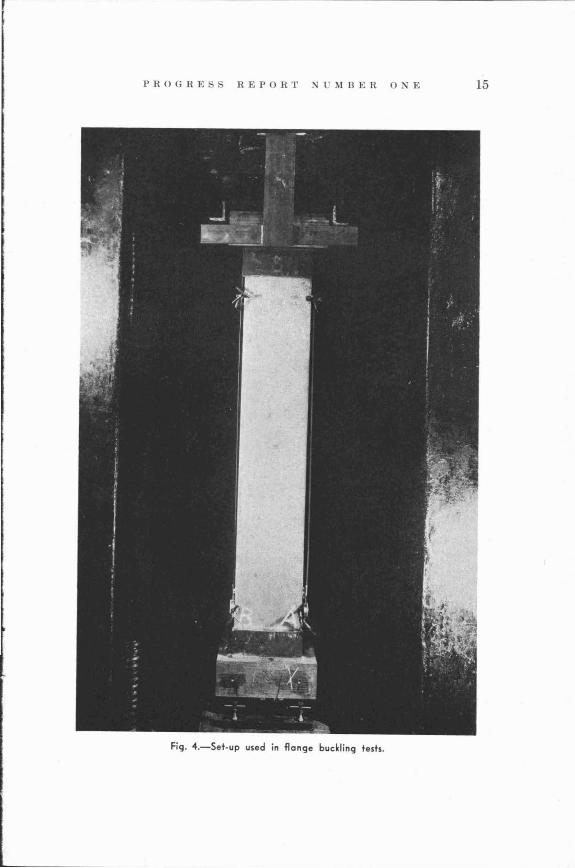
Fig. 4.-Set-up used in flange buckling tests.
PROGRE REPORT ~UMBER ONE 15
o
,....0)
50000
:'ilI-<
ti.40000 ,-,
l'j/
,
"Jt.-'>Z
30000 Q
l'j
rt1
.E >-3g-, l'j
"- 20000 l'j:!a t.-'.!:..
Scale 0..0~
iii 0.0004"1. t.-'10000 c:
~
Zrt1
UNIT STRAIN
Fig. 5.-Typical stress-strain diagrams for. structural carbon and structural silicon steels in tension and compression.
PROGRESS REPORT NUMBER ONE 17
I"LMox.1 ~st Load 395.0 ki s
..--Avg. Str 'in in all fc ur Flange!)
IAxially Lpaded. Tl st No. S3
I
I Max. est Load 242.5 k~ I
I
# -
£~
~i
/ .......-Avg. St ain in St essed FI pnge~ - .......
Ir'v' ..., 'v.;) IV."" IV
II-I/ ,
~~
300
50
200
250
350
~ 150~
I~o
.3 100
readings on the four corners remained nearly the same up to maximumload in the case. of the axially loaded specimens. The average of thesefour readings is shown in the case of a typical axially loaded specimenin Fig. 6. The average of the pair of compressometers on the loadedflange is also shown in Fig. 6 for a specimen loaded at the kern. Thewell 'defined break in the load-deformation curve near maximum loadis typical of these test results.
400
Avg. Strain over 46 II
Fig. 6.-Typical test results, flange buckling tests.
18 WIDE FLANGE STEEL COLUMNS
The maximum test load was taken as a criterion of failure. Becauseof the sharp break in the load deformation curves near maximum load,the load at a "general yield" determined by an average strain offset of0.002 was in all cases within a few per cent of (or identical with) themaximum load. The lack of reserve strength between yielding andultimate in the case of these relatively short columns would seem to betypical of the unusually thin flanges of the test specimens.
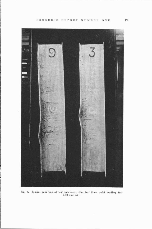
Fig. 7 shows the typical condition of the test specimens after removalfrom testing machine.
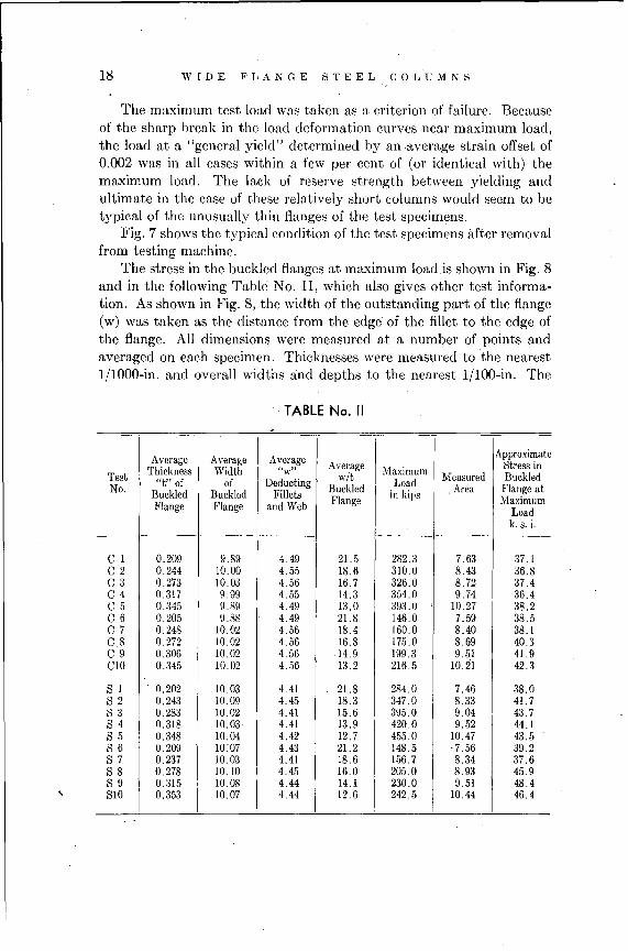
The stress in the buckled flanges at maximum load.is shown in Fig. 8and in the following Table No. II, which also gives other test information. As shown in Fig. 8, the width of the outstanding part of the flange(w) was taken as the distance from the edge' of the fillet to the edge ofthe flange. All dimensions were measured at a number of points andaveraged on each specimen. Thicknesses were measured to the nearest1/1000-in. and overall widths and depths to the nearest 1/100-in. The
. TABLE No. II
-Average Average I Average I Approximate
Thickness Width "w" Average Maximum Stress inTest "t" of of Deducting wit Load Measured BuckledNo. Buckled Buckled Fillets Buckled
Iin kips Area Flange at
Flange MaximumFlange Flange and Web Loadk. s. i.
------ ------
C 1 0.209 9.89 4.49 21.5 282.3 7.63 37.1C 2 0.244 10.00 4.55 18.6 310.0 8.43 36.8C 3 0.273 10.03 4.56 16.7 326.0 8.72 37.4C 4 0.317 9.99 4.55 14.3 354.0 9.74 36.4C 5 0.345 9.89 4.49 13.0 393.0 10.27 38.2C 6 0.205 9.88 4.49 21.8 146.0 7.59 38.5C 7 0.248 10.02 4.56 18.4 160.0 8.40 38.1C8 0.272 10.02 4.56 16.8 175.0 8.69 40.3C9 0.306 10.02 4.56 14.9 199.3 9.51 41.9e10 0.345 10.02 4.56 13.2 216.5 10.21 42.3
S 1 . 0.202 10.03 4.41 21.8 284.0 7.46 38.082 0.243 10.09 4.45 18.3 347.0 8.33 41.783 0.283 10.02 4.41 15.6 395.0 9.04 43.78 4 0.318 10.03 4.41 13.9 420.0 9.52 44.18 5 0.348 10.04 4.42 12.7 455.0 10.47 43.58 6 0.209 10:07 4.43 21.2 148.5 -7.56 39.28 7 0.237 10.03 4.41 18.6 156.7 8.34 37.68 8 0.278 10.10 4.45 16.0 205.0 8.93 45.98 9 0.315 10.08 4.44 14.1 230.0 9.51 48.4810 0.353 10.07 4.44 12.6 242.5 10.44 46.4
PROGRESS REPORT ~~MBER n~E 19
Fig. 7.-Typical condition of test specimens after test (kern point loading, test5-10 and 5-7).

20 WIDE FLANGE STEEL COLUMNS
stress in the buckled flange was taken as PjA in the case of the axiallyloaded specimens and 2PjA in the case of those loaded at the kern. Inthe latter case the stress would be strictly correct only in the elasticrange, but gives an indication of the stress at failure in the same termsthat would be used in calculating the working load by the designer.
Fig. Salso shows the critical stresses used as a design baiSis byMoisseiff and Lienhard18• These are obtained by multiplying the allowable values by the factor of safety of 2.00 which they propose. All ofthe test values are above the Moisseiff and Lienhard curves, increasinglyso as the ratio of wit increases. This is due to the partial restraintoffered by the unbuckled web along one edge of the outstanding flangeleg.
50,-----,.----;---.....--.-,.----'----,.---------,
W45 t-----1.........~__+--_+---\t-'''r--_+_--__r__+I__.:,_-__l
'c::J 30 r=9f>.+.l'\Il,-A-f-,.J:~~;eFf8l'4,~l!Af}---="~&.rlf"'c_~~r_:_-+_-___l
--.. do.-5 icon 5te- do
25 t---+---t---+---+----J---p~..._:4lIor_--1
Avg. Rot 0 W of B ckled Flo ges20 8~-----7;IO:;---~1~2--=.--t14;;-1-....:......=+,;16;.:.:.:..::....:....~18~:.-...--;2:;l;:O;---"2l",2-~24
Fig. a.-Stress in buckled flange at maximum load.
It should be noted that in the axially loaded specimens the averagecritical stresses in all cases are somewhat below the upper yield pointnoted in the coupon tests. In the case of the silicon structural steel thematerial had only a slightly higher upper yield point than the specification minimum of 45 k. s. i., which is also the value assumed by Moisseiffand Lienhard. The carbon structural steel in the test specimens hadan average upper yield point of 41.3 k. s. i. whereas Moisseiff and Lien-
I.
PRO G RES S REP 0 R T N U M B E RON E 21
hard assume 36 k. s. i. and the A.S.T.M. specification minimum is33 k. s. i. Structural steels testecl at the Fritz Laboratory have occasionally had upper yield points below 33 k. s. i. and lower yield pointsin the neighborhood of 30 k. s. i. Outstanding parts of structural steelsections made of such steels may be expected to buckle plastically atstresses somewhat below the Moisseiff-Lienhard curve. in Fig. 8.
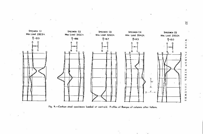
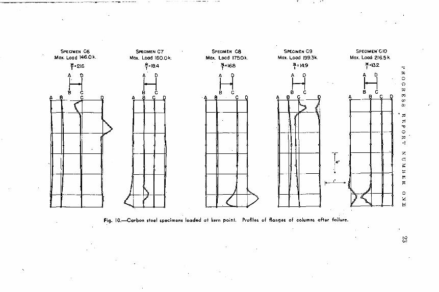
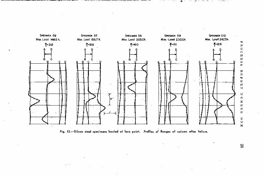
A record of the final buckled or bent shape along the outer edge ofeach flange in each test is shown in Fig. 9, 10, 11, and 12. The offsetsnoted in these figures represent the buckled shape after considerable
.plastic deformation and after removal from the testing machine. Theshape of these waves, with sharp peaks, is typical of plastic buckling,in contrast to the less peaked wave frequently encountered in elasticbuckling. .
SPEciMEN C5Max. Load 393.0k.
i-=13.0
A D
HB C
A B C [
~ ~
IV '/'i"<~
V,\
D
SPECIMEN G4
Max. Load 354.0k.
:r=14.3
H1,
(,I, ,
"[)I
I
SPECIMEN G3
Max. Load 326.0k.
i-=16.7
A D
HB G
A D
~/V"'.
SPECIMEN C2
Max. Load 310.0 k
1'"18.6
HB C
A
~ ~
':::: V~
SPECIMEN CI
Max.l.Dad 282.3 k.
i- =21.5
A D
HB C
A B ·D
1
JD~1\
I
Fig. 9.-Carbon steel specimens loaded at centroid. Profiles of flanges of. columns after failure.
oZl'j
A I
~~
~~
A I
b l."A I C I
) t>.,.
( D
A· (
J '\( V
SPECIMEN C6 SPECIMEN C7 SPECIMEN C8 SPECIMEN C9 SPECIMEN' C10Max. Lood 146.0k. Max. Load 160.0 k; Max. Load 175.0k. Ma~. Load 199.3k. Max. Load 216.5 k.
f:216 *:184 1'"16B '=14.9 f=13.2
A 0 H H A 0 A 0
H H HB C B C B C B C B C
A B C
(
f)
Fig. IO.-Carbon steel specimens loaded at kern point. Profiles of flanges of columns after failure.

SPECIMEN SIMax. Load 284 k.
T· 2 1.8
SPECIMEN S2Max. "-cod 347 k.
f· 18.4
SPECIMEN S3Max. Load 395.0 k.
:t!.=16.8, -
SPECIMEN 54Max. Lopd 420.0 k.
+14.9
SPECIMEN 55Max. Load 455.0k.
f=132
A
A 0
HB BC C 0
A 0
HB C
ABC o
A 0
HB C
ABC o
A 0
HB C
ABC 0 A
A -0
HB C
BCD
K\ ,
( b~
V
I
- ~ 0/
>~\.
'~r/
V"
,l~ ;t>v\
-"
Fig. II.-Silicon steel specimens loaded at centroid. Profiles of flanges of columns after failure.
'---'~----- ---------~~-
SPECIMEN S6Max. Load 1485 II,
r- 212
H8 C
A [
~,,-
'>--I
"
SPECIMEN S7Max. Load 156.7 k.
""186
HB C
A E
~ -I
-i?\
\ ~
SPECIMEN S8Max. Load 205.0k.
"-160
A 0
HB C
A
('Il
<
SPECIMEN S9Max.' Load 230.0k.
f- 14.1
HB C
A C
~ I)\
SPECIMEN S10Max. Load242~k.
f-12.6
HB C
A B· C
11
\ ,(1/ . I <
/\II If
, oZt'J
Fig. 12.-Silicon steel specimens loaded at kern point. Profiles of flanges of column after failure.

26 WIDE FLANGE STEEL COLUMNS
EFFECT OF BEAM CONNECTIONS ON LOCALCOMPRESSIVE STRENGTH OF COLUMN FLANGES
The purpose of this part of the program was to compare the effectof various types of building connections on the local buckling of columnflanges. Three specimens as shown in Fig. 13, 14, and 15 were orderedfrom a structural steel fabricator. A study 'of the effect of welded topangle connections on the bending of column flanges had been made byLyse and Mount19
. On the basis of one of the most critical cases indicated in this report, the riveted connection and welded tie plate connection were designed in such a manner as to apply essentially the sameload, per inch of connection, to the column flange. By so designing thespecimens it was thought that they were put on an equal basis since ineach case the same line load was applied to the column.
The same bearing block and knife edge as previously described wereused to apply load to the column but the lower bearing block was usedwithout a knife edge to insure stability of the set-up. The specimenswere set up in the testing machine and a trial column load applied.
I~ It)' .j
S/,I,c.. TorL~odi'l!l
i3~Oh>.s'
"AILS
10' J..,F 6J -'1-9""V
\
) t t ~"-,I
"< ~ ...~... '/;;#",1 Weld
\" 3'''3x ~. /II.<:
l' . .,~
+ -+
I \ 1()·1.-""-~9'.....
~+'X6X3/; L~'-ok; ~/; h"//el W~/d
'""I'(S,PCCII'1E"N DET,
I(J'
Fig. 13.-Welded top angle and seat connection.
PROGRESS REPORT NUMBER ONE 27
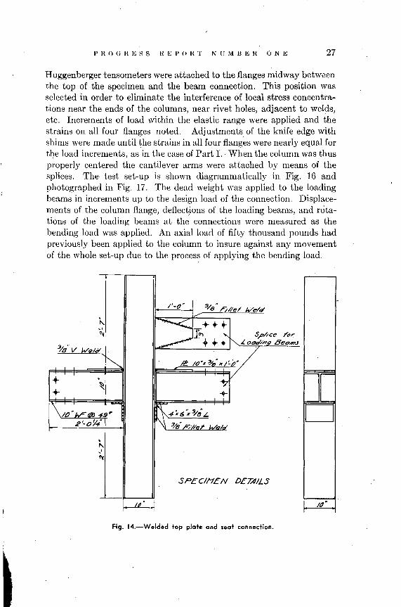
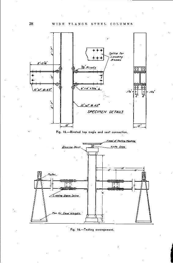
Huggenberger tensometers were attached to the flanges midway betweenthe top of the specimen and the beam connection. This position wasselected in order to eliminate the interference of local stress concentrations near the ends of the columns, near rivet holes, adjacent to welds,etc. Increments of load within the elastic range were applied and thestrains on all four flanges noted. Adjustments of the knife edge withshims were made until ~he strains in all four flanges were nearly equal forthe load increments, as iIi the case of Part 1.. When the column was thusproperly centered the cantilever arms were attached by means of thesplices. The test set-up is shown diagmmmatically in Fig. 16 andphotographed in Fig. 17. The dead weight was applied to the loadingbeams in increments up to the design load of the connection. Displacements of the column flange, deflect,ions of the loading beams, and rotations of the loading beams at the connections were measured as thebending load was applied. An axial load of fifty thousand pounds hadpreviously been applied to the column to insure against any movementof the whole set-up due to the process of applying the bending load.
I'-()~ :3/8 " rille, Wei.,. ./
"'- ~.++-+-"~ ~ '- . S,Phce T()~
~8"V Weld~ ~ ... ..- ~ L 0<74'/"9 8eo#?J
~ 'd"~',I'y~
+ ,~ ~
+ +
\/().~tffl) .;. , ~4:;'6':"~';LR'-OY.,." 3,18' Nile;'- VBIa"
,"'-,I
l'(
S?EClt1EN D£J;4ILS
Ill'
Fig. 14.-Welded top plate and seat connection.
28 WIDE FLANGE STEEL COLUMNS
SPEClt1eN DeTAILS
t...I
+....\
"<:r(
/()·L~ ..... "'-9"
/tJ
r ++~\ +++
SI'/ke Tor'!'OOtT/i'lyQI90..,S
/y./
00 00
Ia>a> (5,
~. ~.~
Fig. 15.-Riveted top angle and seat connection.
7iI.lnA-- l'?aclNifW
Aeor//1,A Bloc,/(--u: H,,,'" cd".,
. '-J 1II
/R'
.~ 2'=1/P'-
R"/I,,r
'ldl/
r -r: ~-~ n[: :1
~~ 0",.., S/'/ke
~
r~JPO'.. 'fir /)"0'; Wel_n;s
Ii /'.V-II I I~ h n
--<-
Fig. lb.-Testing arrangement.
PROGRESS REPORT XliYBER ONE 29
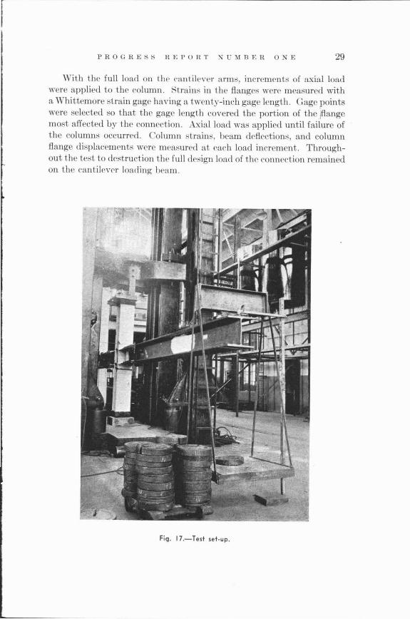
\Vith the full load on the eantilE'ver arms, increments of axial loadwere applied to the column. Strain.' in the flanges were measured witha Whittemore strain gage having a twenty-inch gage length. Gage pointswere selected so that the gage length covered the portion of the jflangemo·t affected by the connection. Axial load was applied until failure ofthe columns occurred. Column strains, beam deflections, and columnflange displacements were measured at each load increment. Throughout the test to destruction the full design load of the connection remainedon the eantilever loading beam.
Fig. 17.-Test set-up.
30 WIDE FLANGE STEEL COLUMNS
The average of tensile test results of material in the column flangeand web, weighted in proportion to respective areas, were:
Yield point. . . . . . . . . . . . . . . . . . . . . . . .. 37.6 k. s. i.Ultimate. . . . . . . . . . . . . . . . . . . . . . . . . .. 61.7 k. s. i.Per Cent Elongation in 2 in. . 44.4
A summary of the test results is given in the following Table No. III
TABLE No. III
Type of Connection
Riveted Angle Connection. . .. ..Welded Angle Connection .. , . . . . . .Welded Plate Connection .
Average Stressin k. s. i.
in Column atMaximum Load
33.634.635.3
EfficiencyBased on
Yield Point
0.890.920.94
Table III indicates that the welded top plate connection was leastharmful in lowering the maximum capacity of the column whereas theriveted angle was the most harmful. The welded top plate stiffens theflange and inhibits bending of the outstanding parts. On the other hand,the welded top plate in a different design might introduce local concentration of stress into the column web, but this did not appear to beharmful in the present instance at design loads.
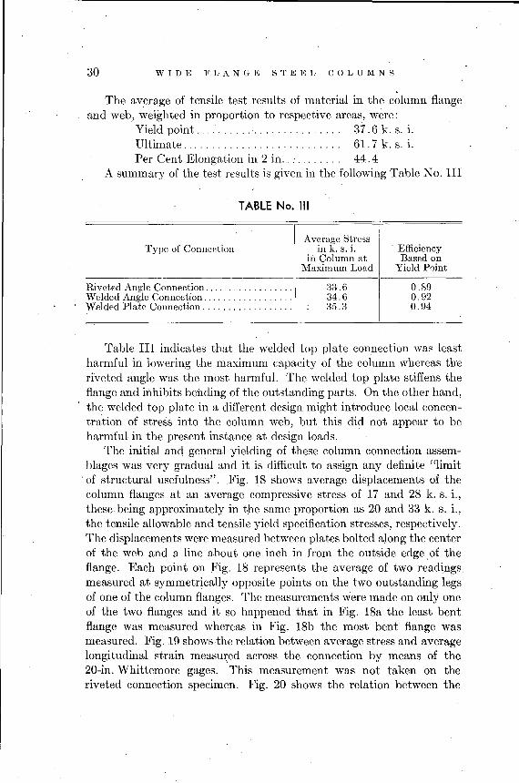
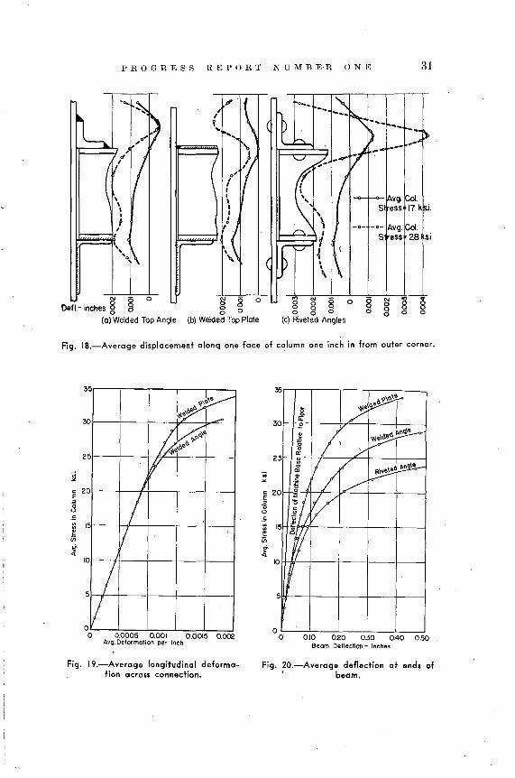
The initial and general yielding of these column connection assemblages was very gradual and it is difficult to assign any definite "limitof structural usefulness". Fig. 18 shows average displacements of thecolumn flanges at an average compressive stress of 17 and 28 k. s. i.,these being approximately in the same proportion as 20 and 33 k. s. i.,the tensile allowable and tensile yield specification stresses, respectively.The displacements were measured between plates bolted along the centerof the web and a line about one inch in from the outside edge. of theflange. Each point on Fig. 18 represents the average of two readingsmeasured at symmetrically opposite points on the two outstanding legsof one of the column flanges. The measurements were made on only oneof the two flanges and it so happened that in Fig. 18a the least bentflange was measured whereas in Fig. 18b the most bent flange wasmeasured. Fig. 19 shows the relation between average stress and averagelongitudinal strain measur:ed across the connection by means of the20-in. Whittemore gages. This measurement was not taken on theriveted connection specimen. Fig. 20 shows the relation between the
PROGRESS REPORT NUMBER ONE 31
, 01.,17 k,
I
I -0- Avg. 01.IS ress 28 si
Defl._ inches § ~ 0
(0) Welded Top Angle
8 80o 0
(b) Welded Top Plote
§ g 08o 0
(c) Riveted Angles
o '"og
Fig. IB.-Average displacement along one face of column one inch in from' outer corner.
0.10 020 030 040 050Beam Deflection - lnr.hAS
J~I'1\.\0"
- /'2
" / ~~~"\
cr y5 "
1/ / d~'"c'" ~Ii!
~fJ
i~V5 "t,1j
Ii5
oo
10
2
30
" 20§(;<.>.5
'"'""if,t
5
I I~k~.\~ ....
~~<'1>.1>.'
5
fI
5 /II
/1/
5
oo 0.0005 0.001 0.0015 0002
Avg. Deformation per Inch
3
10
2
~ 202<3
Fig. 19.-Average longitudinal deformation across connection.
Fig. 20.-Average deflection at end. of, beam.
32,
WIDE FLANGE STEEL COLUMNS
average stress in the columns and the average deflection at the two endsof the cantilever beams. These deflections were in reference to thelaboratory floor, hence are not quantitatively correct in reference tothe column, but indicate the difference in behavior of the three types.The dashed line shows the deflection of the testing machine base rela-·tive to the laboratory floor. Fig. 20 shows that column stress causedincreased connection rotation even at low loads and the increase ofrotation became greater as column stress increased. The bending moment in the connections was constant, hence the change of deflection inFig. 20 was a function of column stress only. F.ig. 20 indicates rapidly.increasing connection rotation at about the following average stresses:
20 k. s. i. in the case of the riveted connection,25 k. s. i. in the case of the welded top angle connection,30 k. s. i. in the case of the welded top plate connection.
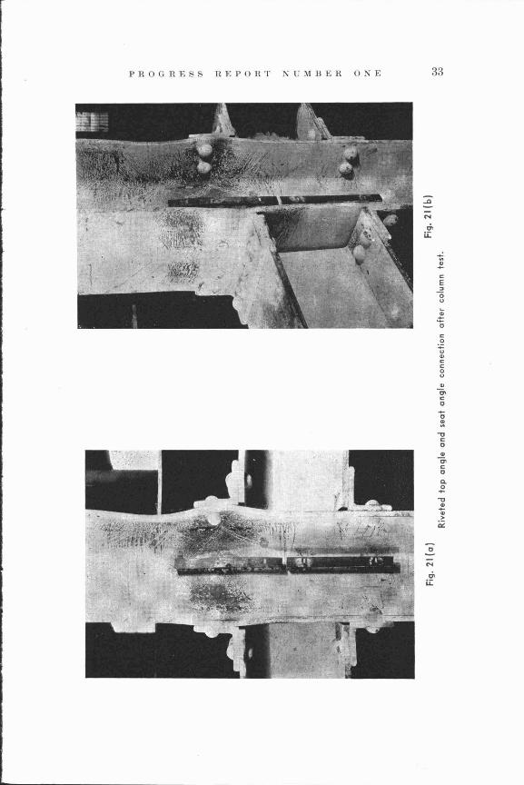
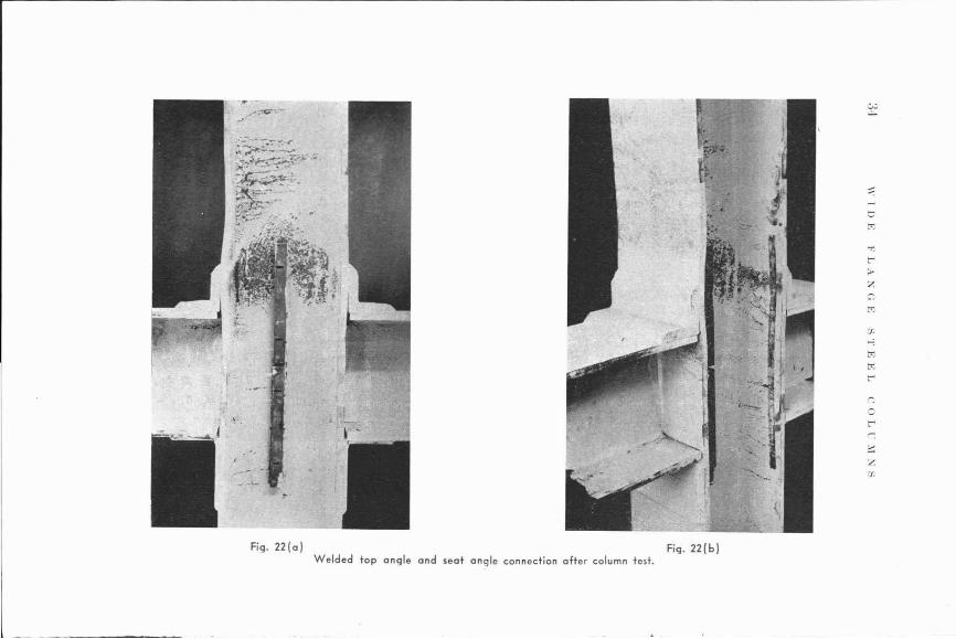
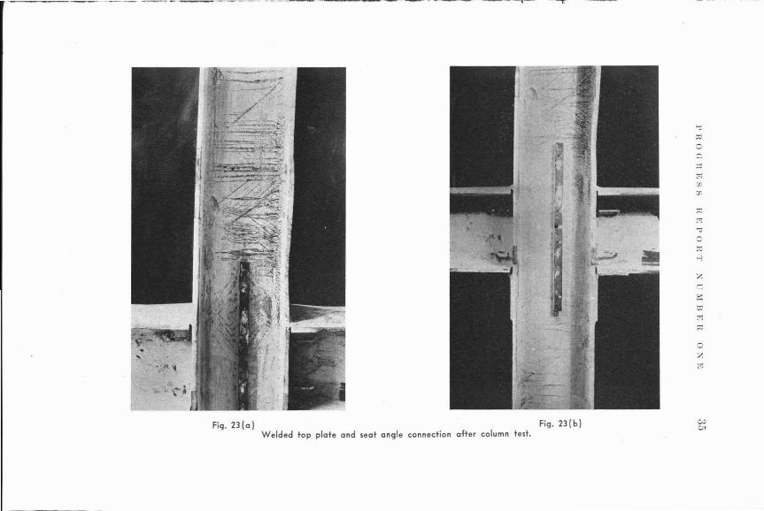
Fig. 21, 22, and 23, illustrate the condition of the test specimensafter removal from the testing machine. It will be noted that thefailure is very similar in the cases of the welded angle and riveted angleconnections. In the case of the riveted angle, the flange buckled thegreatest amount slightly below the rivets, (Fig. 21a) while the weldedangle caused the flange to buckle the greatest just below the top weld(Fig. 22a). In Fig. 23(a) and (b) it may be seen that the buckled ~ave
occurs above the top of the beam, the tie plate connection apparentlyhaving little or no effect upon the failure of the member as a shortcolumn.
PROGRESS REPORT NUMBER ONE 33
A
N
,;,u::
...~.....cE:>
0u~
£0
c0
:;:U..CC0U
~
'"c0...0e:
-0c0..
e;,c0
Q.0...
-0
~.,>
0::
0
N
'"u::
r:Cc:-'
ZTo
_.- - ~_.~~~~------
Fig. 22(alWelded top angle and seat angle connection ofter column test.
Fig. 22(b)
oZt'l
Fig. 23(a) Fig. 23(b)Welded top plate and seat angle connection after column test.
36 WIDE FLANGE S~EEL COLUMNS
SUMMARY AND CONCLUSIONS·
.'.
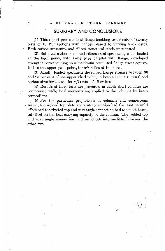
(1) This report presents local flange buckling test results of twentytests of 10 WF sections with flanges planed to varying thicknesses.Both carbon structural and silicon structural steels were tested.
(2) Both the carbon steel and silicon steel specimens, when loadedat the kern point, with knife edge parallel with flange, developedstrengths corresponding to a maximum computed flange stress equivalent to the upper yield point, for wit ratios of 16 or less.
(3) Axially loaded specimens developed flange stresses between 90and 95 per cent of the upper yield point, i~ both silicon structural andcarbon structural steel, for wit ratios of 18 or less.
(4) Results of three tests are presented in which short columns arecompressed while local moments are applied to the columns by beamconnections.
. '(5) For the particular proportions of columns and connections. tested, the welded top plate and seat connection had the least harmful
effect and the riveted top and seat angle connection had the most harmful effect on the load carrying capacity of the column. The welded topand seat angle connection had an effect intermediate between theother two.
PROGRESS REPORT NUMBER ONE
LIST OF REFERENCES
37
[1] "Short Steel Collunn Progress Report" by LLOYD T. CH~JNI"Y, anunpublished memorandum distributed by Fritz Laboratory,,July 1939.
(2] "llIemorandum on Steel Colwnn Formulas and Tests" distributedon .JanuarJ~ 28, 1941, for discussion by the A. S. C. K Committee on Design of Structural Members.
[3] "Lateral /3ucklin(J of I-Section Columns With Eccentric E(ul LoadsIn Plane Of Web" by BRUOJ JOHNSTON,A. S. M. K Journal ofApplied Mechanicfl, December 194]., pp. A-17G-A-180. Theoretieal study of the lateral buckling problem in the elastie range.
[4] "Cmnpression And Tension Tests Of Stnlctw"(tl Alloys" by BRUCE.JOHNSTON and FRANCIS OPILA. Proeeedings of the AmerieanSociety for Testing Materials, Vol. 41, 1941, pp. 552 to 578.Compares eompressive and tensile characteristies of varioussamples of earbon, silicon, and low-alloy struetural steels,clireetly related to the problem of column design.
[,5] "Rational Colwnn Analysis" by .I. A. VAN DEN BROEK, a diseussionof this paper by Bruee Johnston, ,The Engineering Journal,
. ,June 1942. Includes part of (2) relating to columns aeting asparts of frames.
[(-j] "Desi(Jn of Structnral Members". First Progress Report of theCommittee of the Struetural Division on Design of StrueturalMembers. Proceedings, Am. Soc. C. K,April 1942, pp. 5G5to 574. Projeet No.2, on "Design of Structural Alloy Columns"is outlined in this report.
[7] Final Report Of The Special Corn:rnittee On Steel Colu'lnns AndStruts, Transactions, Am. Soc. C. K Vol. LXXXIII (19191920), pp. 1584-1G88.
[8] Progress Report Of The Special COIII:llu:ttee On Steel Column Research, Transactions, Am. Soe. C. K Vol 89, (193G), p. 1485.
[9] Second Pro(Jress Report Of The Special Cmmnittee On Steel ColurnnResew'ch, Transactions, Am. Soc. C. E., Vol. 95, 1931, p. 1152.
[10] F1:nal Report Of The Special Cornmittee On Steel Column Research,Transactions, Am. Soc. C. K, Vol. 98, 1933, p. 137G.
[11] "Columns" by K H. SALMON, Oxford Teehnical Publications, 1921.Complete Bibliography up to 1920.
[] 2J "Theory Of Elastic Stability" by S. TIMOSHENKO, McGraw-HillBook Company, Inc., New York and London, 1936. .
38 WIDE FLANGE STEEL COLUMNS
[13] F1:rst, Second, and F1:nal Reports Of The Steel Struct1J.,res ResearchCommittee, Department of Scientific and Industrial Research,Great Britain, 1931, 1934, 1936.
[14] "Colu-mn Curves And Stress-Strain Diaarams" by WILLIAM R. OSGOOD, Hesearch Paper No. 492, U. S. Bureau of Standards,October 1932. .
[15] "Torsional And Fl.exural Bucklina Of Bars Of Thin-Walled OpenSecl1:ons Under Compressive And Bending Loads" by J. N.GOODIER, A. S. M. K Journal of Applied Mechanics, Septernber 1942.
[16] "Principles· of iVlomen,t D1:str£bution 4,pplied To The Stability OfStructural Members" by EUGENE K LUNDQUIST, Proceedings,Fifth International Congress for Applied Mechanics, 1938,pp. 145-149.
[17J "Rational Desian Of Steel Col1l1nns" by D. H. YOUNG, Transactions,Am. Soc. C. K, Vol. 101, 1936, pp. 422-500.
[18J "Theory Of Elastic Stability Applied To Strnctuml Desian" by LEONS. MorSSEIFF and FREDEHICK LIENHARD, Transactions, Am.Soc. C. E., Vol. 106, 1941, pp. 1052-1112 (contains an extensivebibliography) .
[19] "E.ffect Of Rigid Berun-Colu-rnn Connect1:ons On Column Stresses"by INGE LYSE and K H. MOUNT, Research Supplement ofAmerican Welding Journal pp. 25-31, Vol. 17, No. 10, October193,8.
[20] "Column Strenath Of F ari01lS Aluminum Alloys" by TEMPLIN,STURM, HARTMAN, and Hour. Aluminum Research Laboratories Technical Paper No. 1.
[21J Design Specifications For Bridges And Structures Of Al1l1ninumAlloy 27-ST.
[22] Structural Aluminum Handbook.[23] Bethlehem Manual Of Steel Construction Catalogue S-47.[24] "Column Strength Of Tubes Elastically Restrained Aaainst Rotation
At The Ends" by WILLIAM R. OSGOOD, N. A. C. A. ReportNo. 61.5, 1938.