state route 99 / skyway interchange - phase 2state route 99/skyway interchange – phase 2 i table...
TRANSCRIPT
GEOTECHNICAL DESIGN / MATERIALS REPORT
State Route 99 / Skyway Interchange - Phase 2 Chico, California
Prepared by:
BLACKBURN CONSULTING
11521 Blocker Drive, Suite 110
Auburn, CA 95603
June 28, 2007
Prepared for:
MARK THOMAS & COMPANY, INC.
GEOTECHNICAL REPORT State Route 99/Skyway Interchange – Phase 2
i
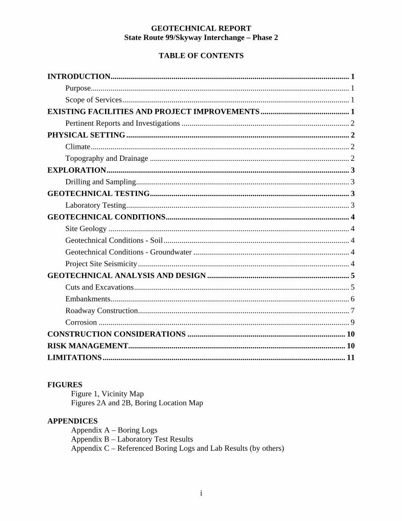
TABLE OF CONTENTS
INTRODUCTION......................................................................................................................... 1 Purpose................................................................................................................................... 1 Scope of Services................................................................................................................... 1
EXISTING FACILITIES AND PROJECT IMPROVEMENTS............................................. 1 Pertinent Reports and Investigations ..................................................................................... 2
PHYSICAL SETTING ................................................................................................................. 2 Climate................................................................................................................................... 2 Topography and Drainage ..................................................................................................... 2
EXPLORATION........................................................................................................................... 3 Drilling and Sampling............................................................................................................ 3
GEOTECHNICAL TESTING..................................................................................................... 3 Laboratory Testing................................................................................................................. 3
GEOTECHNICAL CONDITIONS............................................................................................. 4 Site Geology .......................................................................................................................... 4 Geotechnical Conditions - Soil .............................................................................................. 4 Geotechnical Conditions - Groundwater ............................................................................... 4 Project Site Seismicity ........................................................................................................... 4
GEOTECHNICAL ANALYSIS AND DESIGN ........................................................................ 5 Cuts and Excavations............................................................................................................. 5 Embankments......................................................................................................................... 6 Roadway Construction........................................................................................................... 7 Corrosion ............................................................................................................................... 9
CONSTRUCTION CONSIDERATIONS ................................................................................ 10 RISK MANAGEMENT.............................................................................................................. 10 LIMITATIONS........................................................................................................................... 11 FIGURES
Figure 1, Vicinity Map Figures 2A and 2B, Boring Location Map
APPENDICES
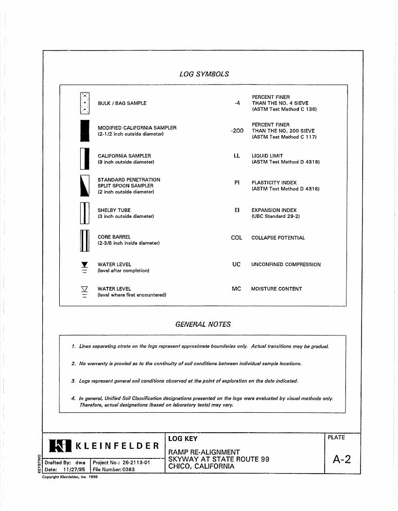
Appendix A – Boring Logs Appendix B – Laboratory Test ResultsAppendix C – Referenced Boring Logs and Lab Results (by others)
Geotechnical Design/ Materials Report for the SR99 / Skyway BCI No. 1157.1 Interchange Project– Phase 2, Chico, California June 28, 2007
1
INTRODUCTION
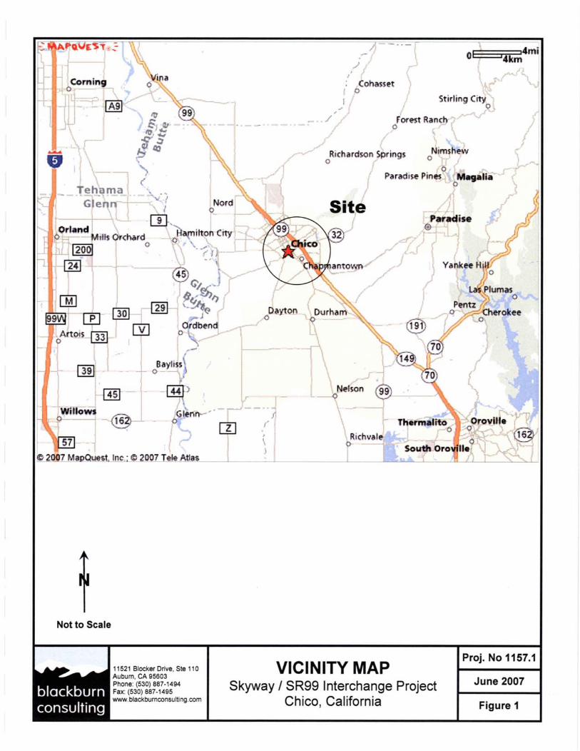
Purpose BCI prepared this Geotechnical Design/Materials Report for the design of the Phase 2 safety improvements of on- and off-ramps at the State Route (SR) 99 / Skyway Interchange. We include recommendations for general grading, embankment construction and widening, pavement structural sections, and soil corrosivity. We show the project location on the Vicinity Map, Figure 1. We prepared this report for Mark Thomas and Company (MTCo) and the City of Chico to use during the design and construction of this project. The design team refers to the project as “Phase 2” improvements at the Skyway/SR99 interchange. Do not use or rely upon this report for locations or improvements other than the described project site without the written consent of BCI.
Scope of Services To prepare this report, BCI:
• Reviewed the proposed layout of site improvements and discussed the project with MTCo design staff.
• Logged and sampled four (4) exploratory borings within the area of proposed improvements.
• Performed laboratory tests on representative soil samples to establish general grading and pavement design parameters.
• Researched site geologic and seismic conditions. • Reviewed and incorporated subsurface data and laboratory test values from a previous
report titled “Geotechnical Report, Skyway at State Route 99 Ramp Improvements” (Kleinfelder, February 2000). The 2000 report was prepared for the Phase 1 improvements at the Skyway/SR99 interchange.
• Performed engineering analysis in support of our recommendations.
Specific items excluded from our geotechnical review include field review of the existing pavement condition, pavement overlay recommendations, and foundation design for sound or retaining walls.
EXISTING FACILITIES AND PROJECT IMPROVEMENTS The project is located in the City of Chico, California. The City is planning Phase 2 improvements to the Skyway/East Park Avenue/SR99 interchange. Phase 2 improvements include:
• Roadway improvements along the southbound (SB) and northbound (NB) shoulders SR99 at the Skyway/SR99 interchange.
• Realignment of the SB SR99 off-ramp at East Park Avenue. • Removal of the SB SR99 loop off-ramp to EB Skyway, and removal of the WB Skyway
to SB SR99, non-signaled intersection on-ramp.

Geotechnical Design/ Materials Report for the SR99 / Skyway BCI No. 1157.1 Interchange Project– Phase 2, Chico, California June 28, 2007
2
• Construction of a new SB loop on-ramp from WB Skyway to SB SR99. • Widening of the East Park Avenue to southbound SR99 on-ramp. • Widening of the WB Skyway to NB SR99 on-ramp.
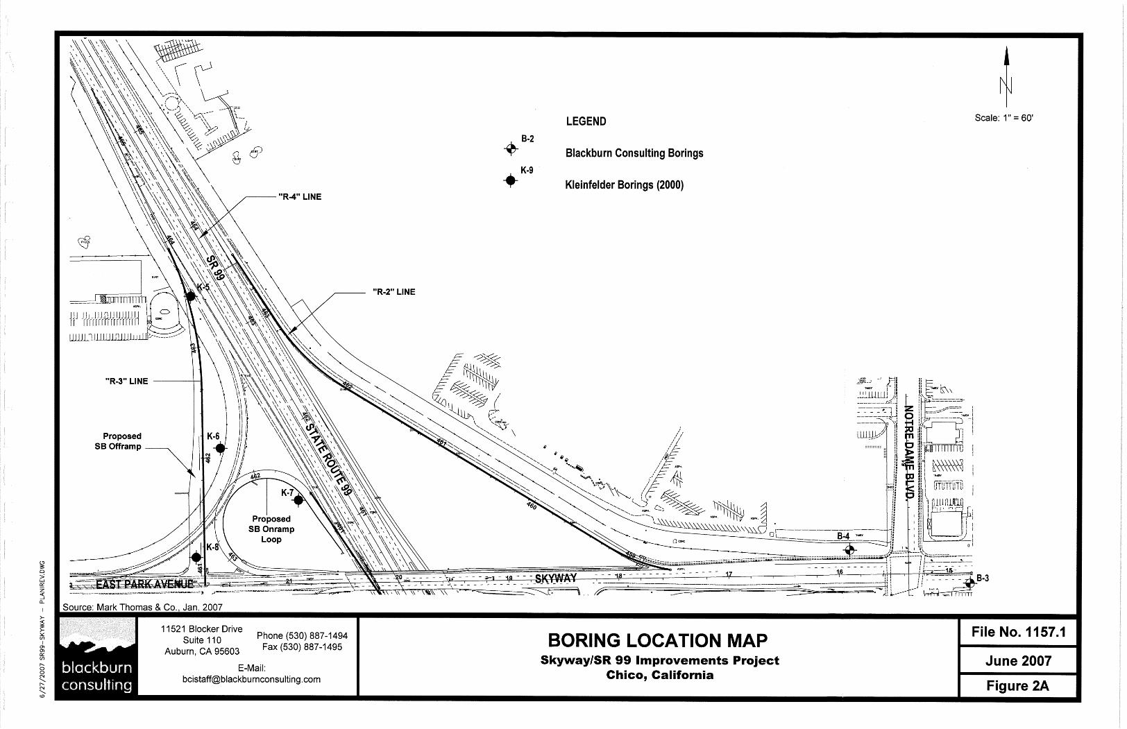
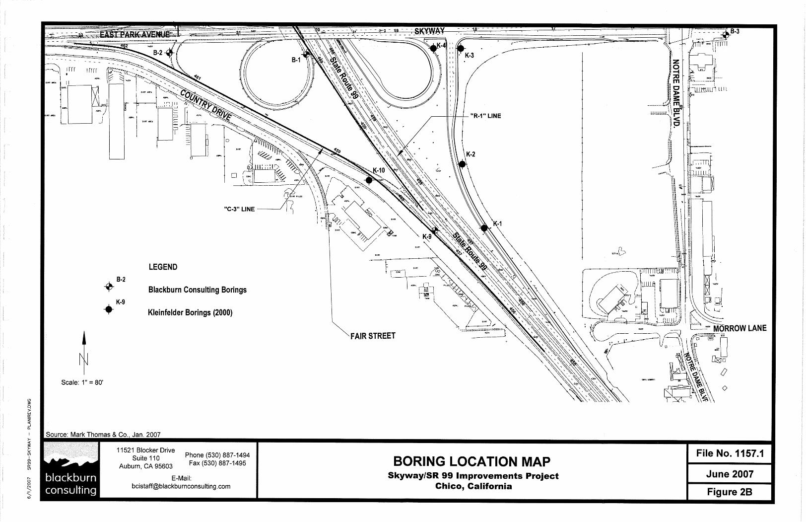
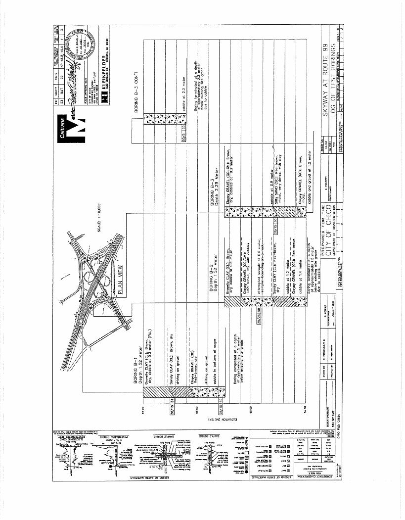
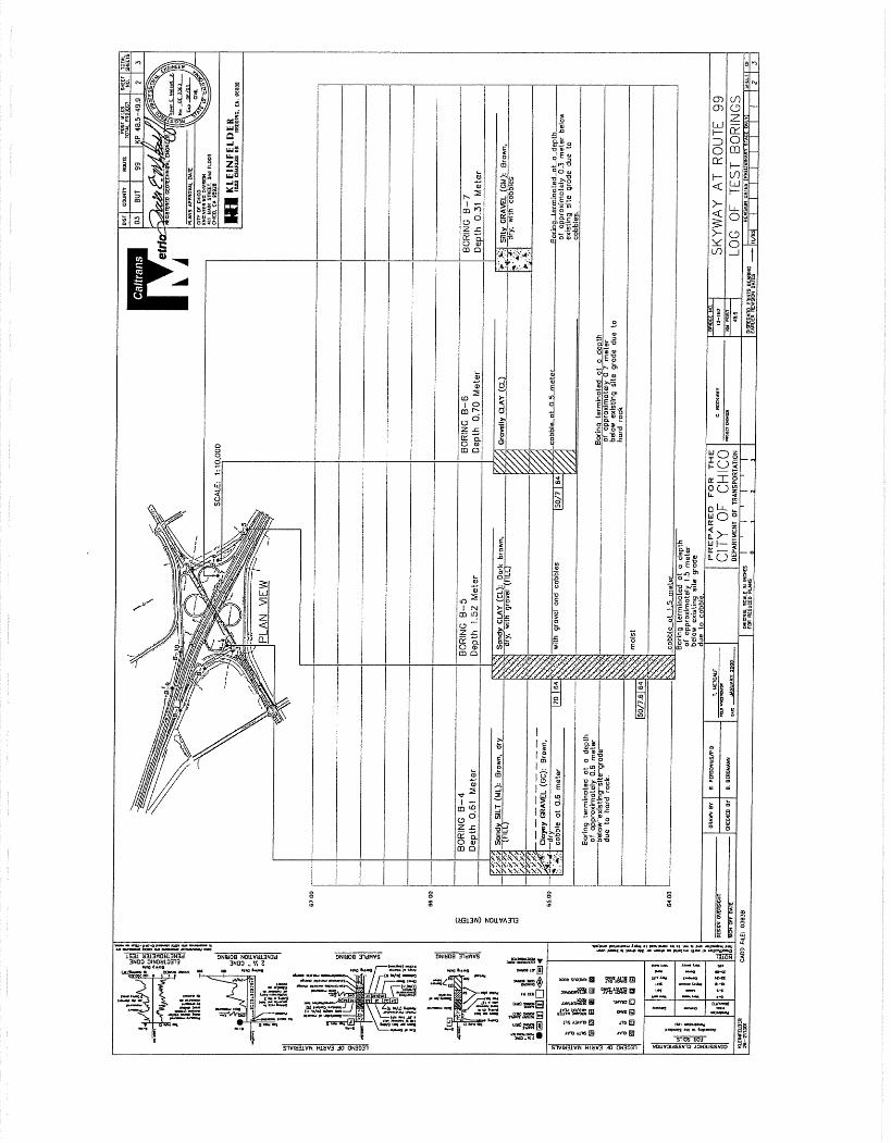
Phase 1 improvements were constructed around 2001/02. The Phase 1 improvements to the existing interchange consisted of a southbound loop off-ramp to Skyway, a northbound off-ramp to either East Park Avenue or Skyway, a southbound off-ramp to East Park Avenue, and a southbound on-ramp that serves both East Park Avenue and Skyway. As a part of the proposed Phase 2 interchange improvements, the City of Chico also plans to widen and improve the at-grade intersections located adjacent (east and west) of the freeway interchange. These include the intersection of East Park Avenue, Carmichael Drive, and Country Drive (to the west), and the intersection of Notre Dame Boulevard and Skyway (to the east). We provide pavement recommendations for the City streets, under “Roadway Construction”, below. We show the proposed SR99/Skyway improvement areas on the Boring Location Map, Figures 2A and 2B.
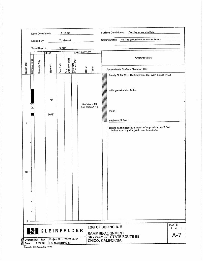
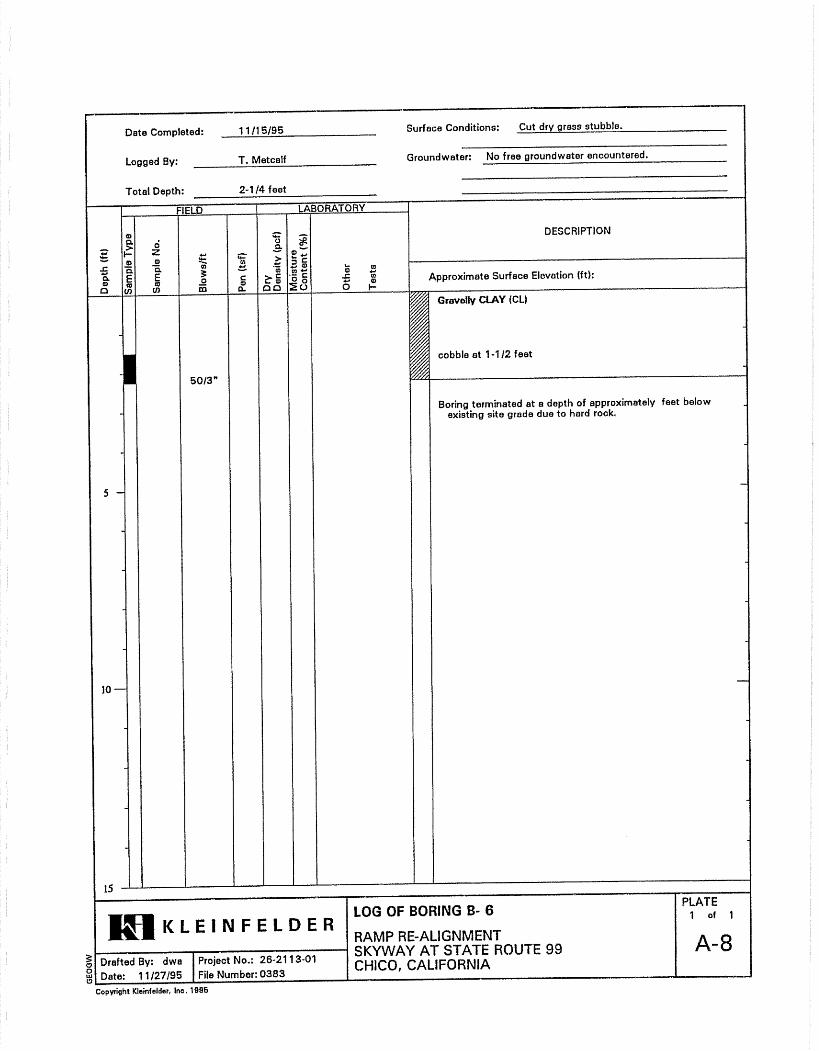
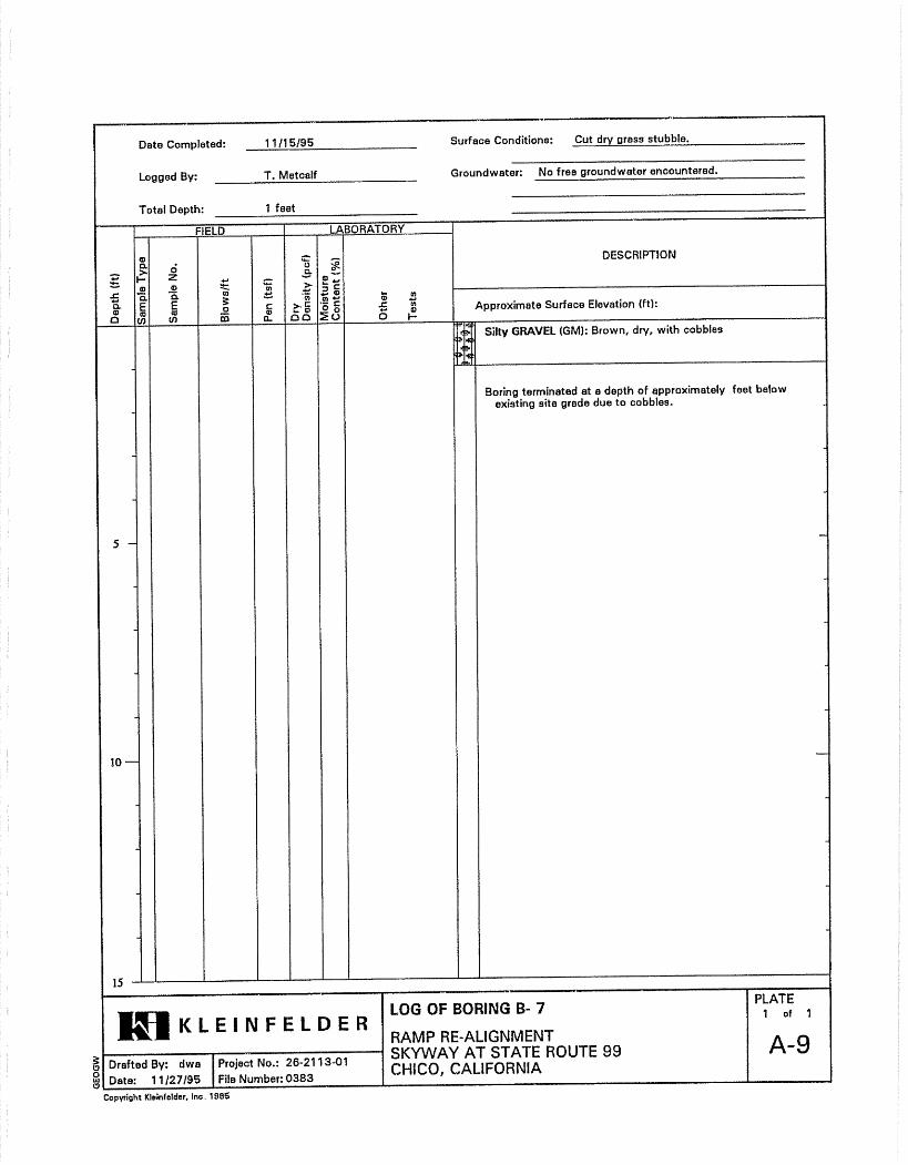
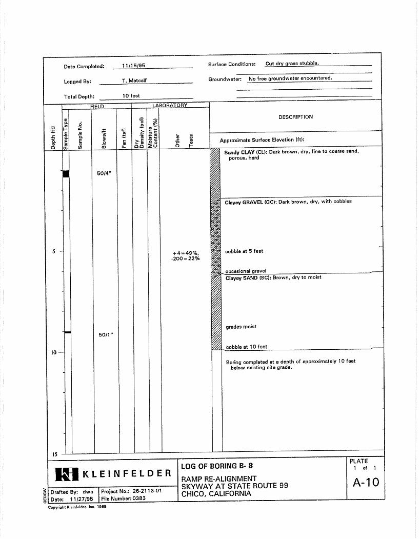
Pertinent Reports and Investigations We reviewed and incorporated pertinent subsurface data from the previously published report for Phase 1 improvements at the interchange. The report is titled “Geotechnical Report, Skyway at State Route 99 Ramp Improvements”, Kleinfelder, February 2000. We include relevant borings logs and laboratory information in Appendix C.
PHYSICAL SETTING
Climate The project site is located near the northeast end of the Sacramento Valley, approximately 2 miles southeast of downtown Chico, California. Rainfall typically ranges from 23 to 26 inches per year, with nearly all precipitation occurring between September and April. Average air temperatures range from 35 to 95 degrees Fahrenheit.
Topography and Drainage The project site topography is generally flat, with a gradual slope to the west and southwest. Previous interchange improvements required cuts and fills of 10 to 20 feet. Commercial and light industrial development surrounds the existing interchange. Existing drainages consist of unlined ditches parallel to SR99, along the ramps, and adjacent to the roads leading to the interchange (East Park Avenue and Skyway). A realigned drainage channel is located along the west side of Carmichael Drive, crosses beneath East Park Avenue, and continues south towards a green belt area southwest of the interchange. Existing embankment slopes are moderate, with grades ranging from approximately 4h:1v (horizontal to vertical) to 2h:1v.
Geotechnical Design/ Materials Report for the SR99 / Skyway BCI No. 1157.1 Interchange Project– Phase 2, Chico, California June 28, 2007
3
State Route 99, Skyway, and East Park Avenue have two travel lanes (each direction) with paved shoulders. Westbound traffic along Skyway must cross traffic at an at-grade, non-signalized intersection to access the southbound on-ramp to SR99.
EXPLORATION
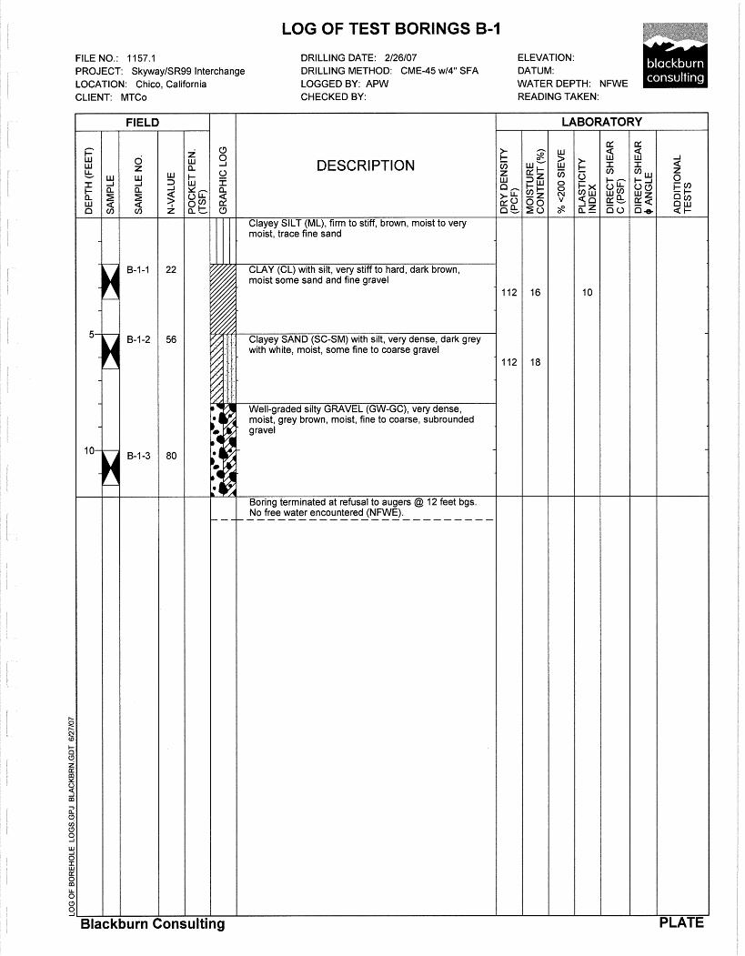
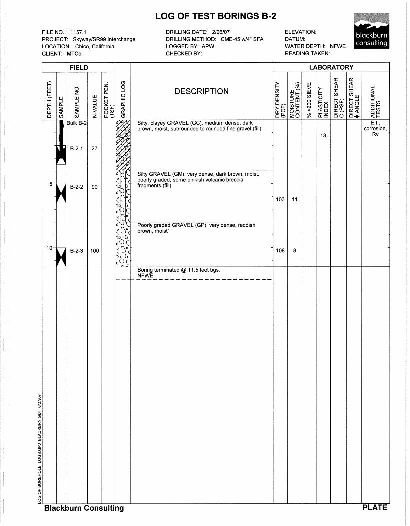
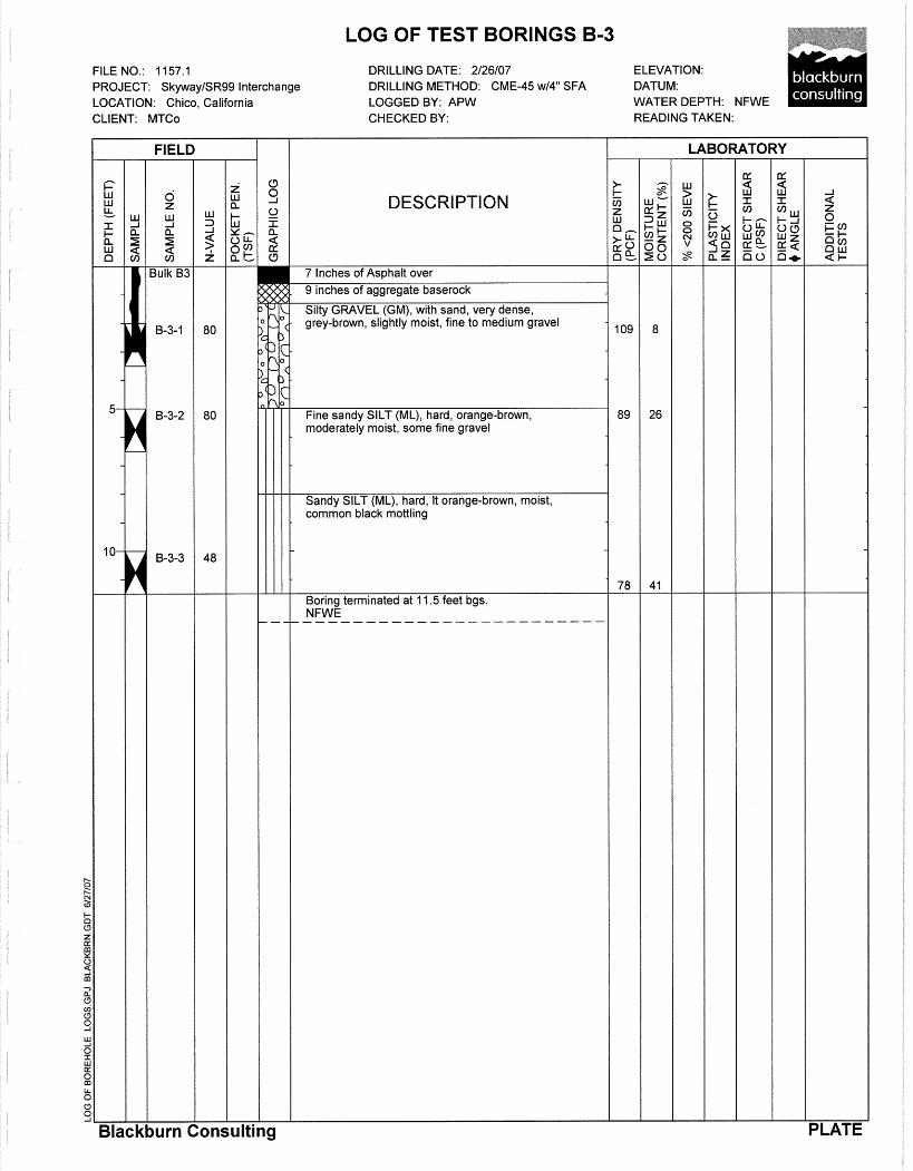
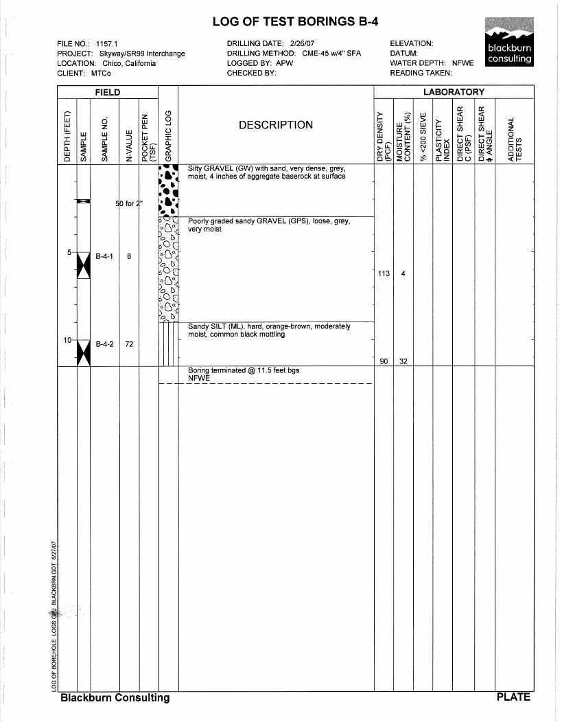
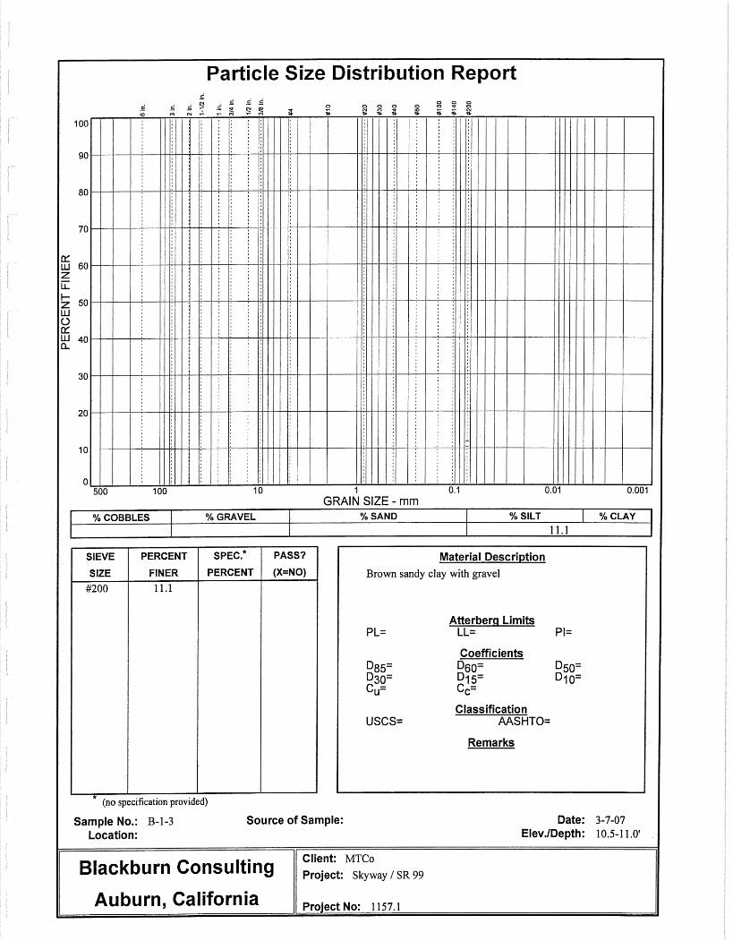
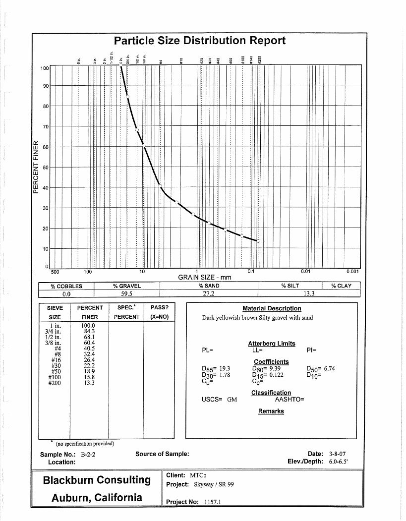
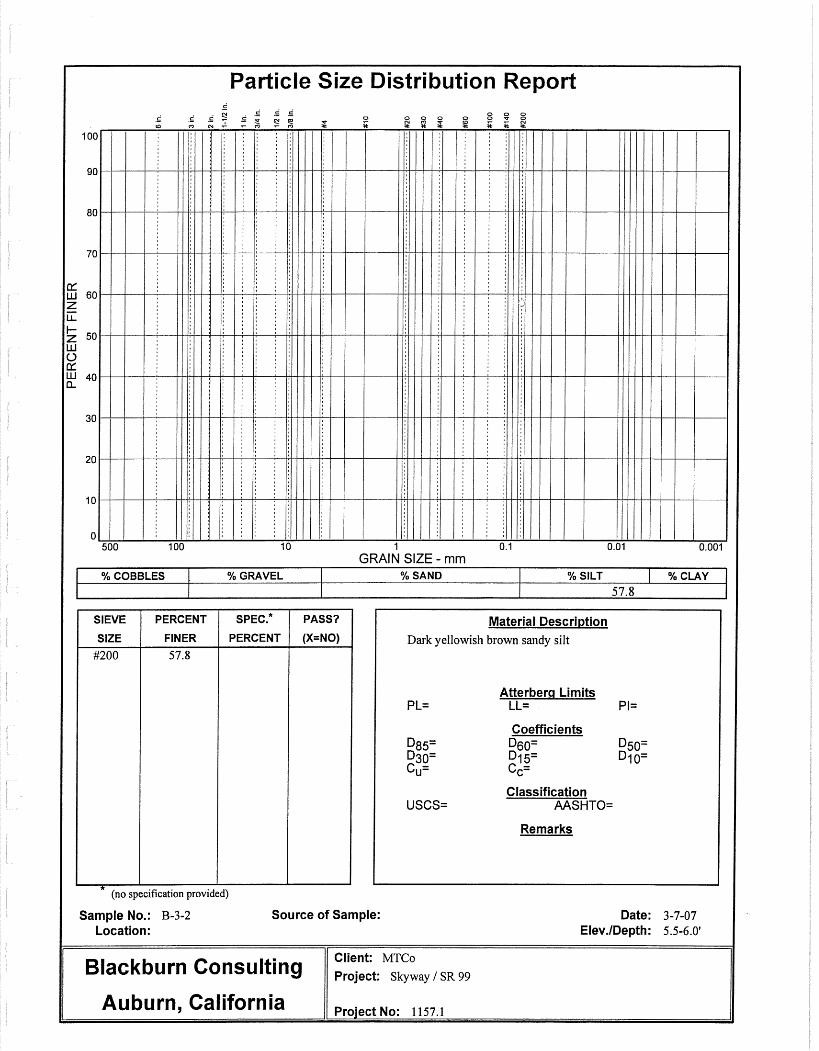
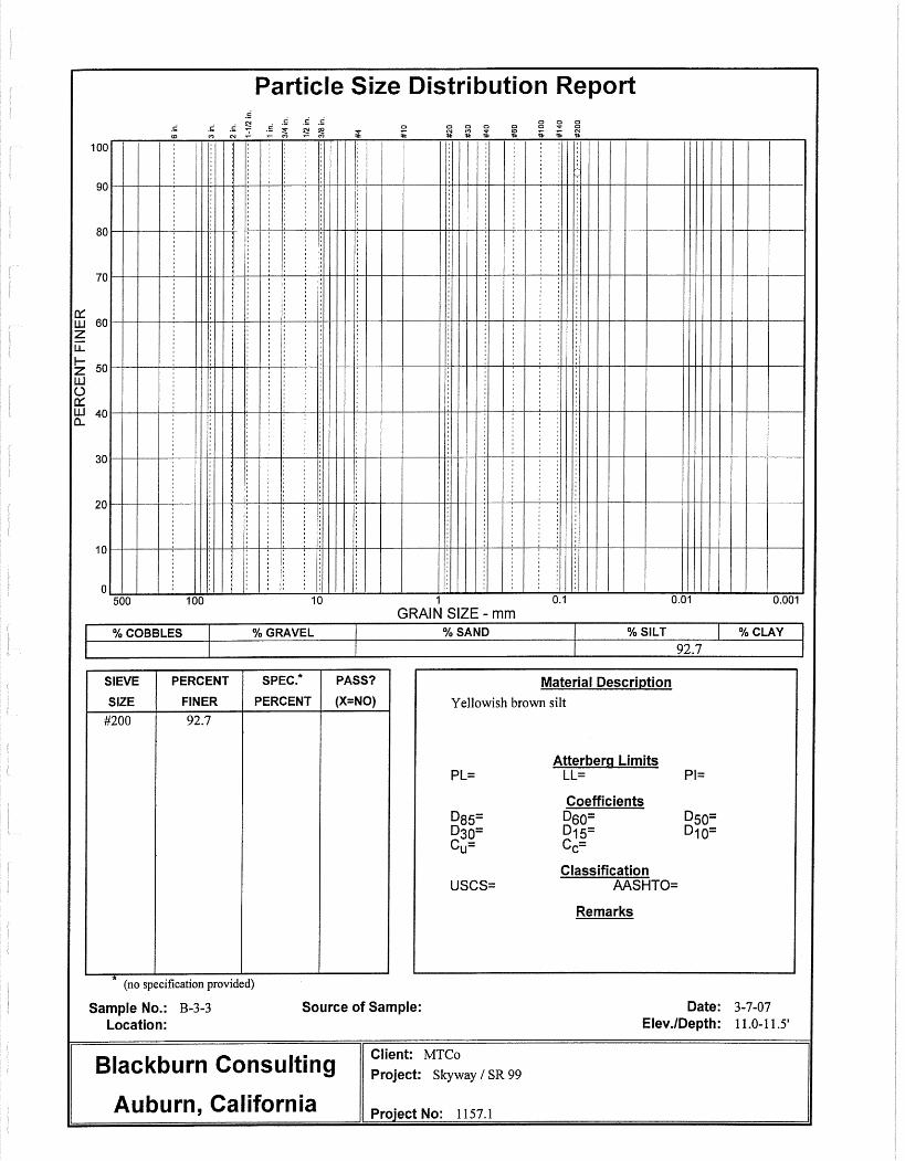
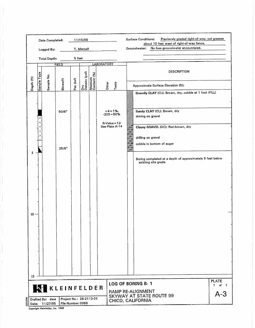
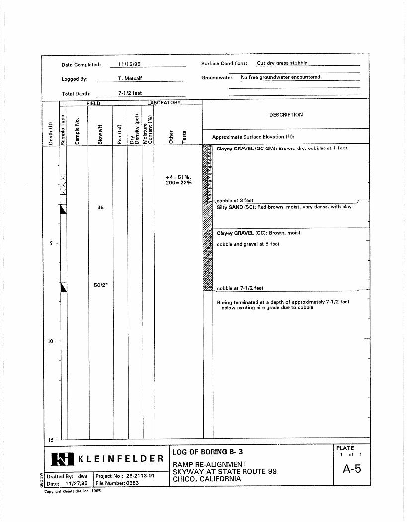
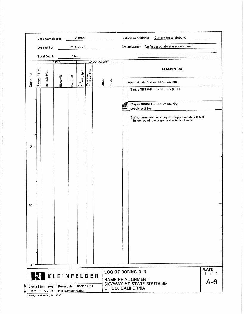
Drilling and Sampling We conducted our field investigation during February 2007. To characterize the subsurface conditions and obtain soil samples for laboratory testing, BCI retained Gularte & Associates to drill and sample four exploratory borings. Gularte used a CME 45, truck-mounted rig to drill the borings to a maximum depth 12 feet. The drill rig used 4-inch diameter, solid flight augers to advance the borings. We conducted soil sampling and blow count data using a Modified California Sampler (MCS) equipped with 2.375-inch I.D. brass liners. We used a 140-lb, automatic trip, safety hammer falling 30-inches to drive the sampler. Our geologist logged the borings and described the soils in accordance with the Unified Soil Classification System (USCS).
GEOTECHNICAL TESTING
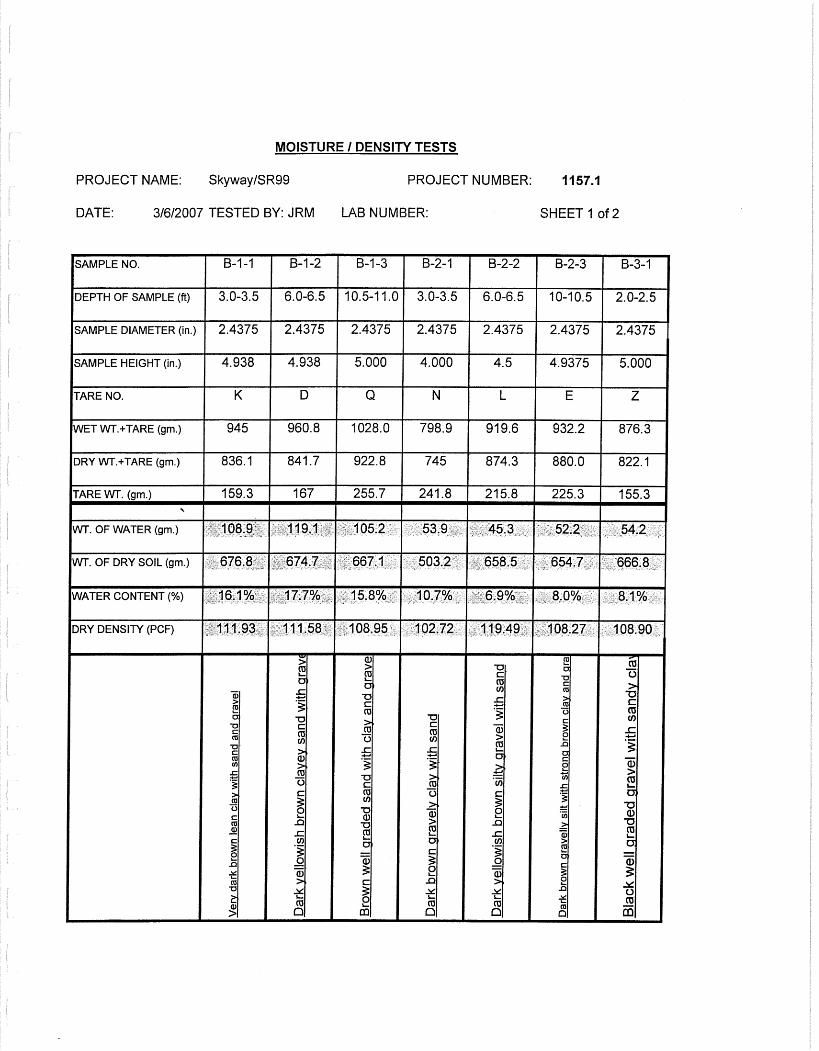
Laboratory Testing We completed the following laboratory tests on representative soil samples:
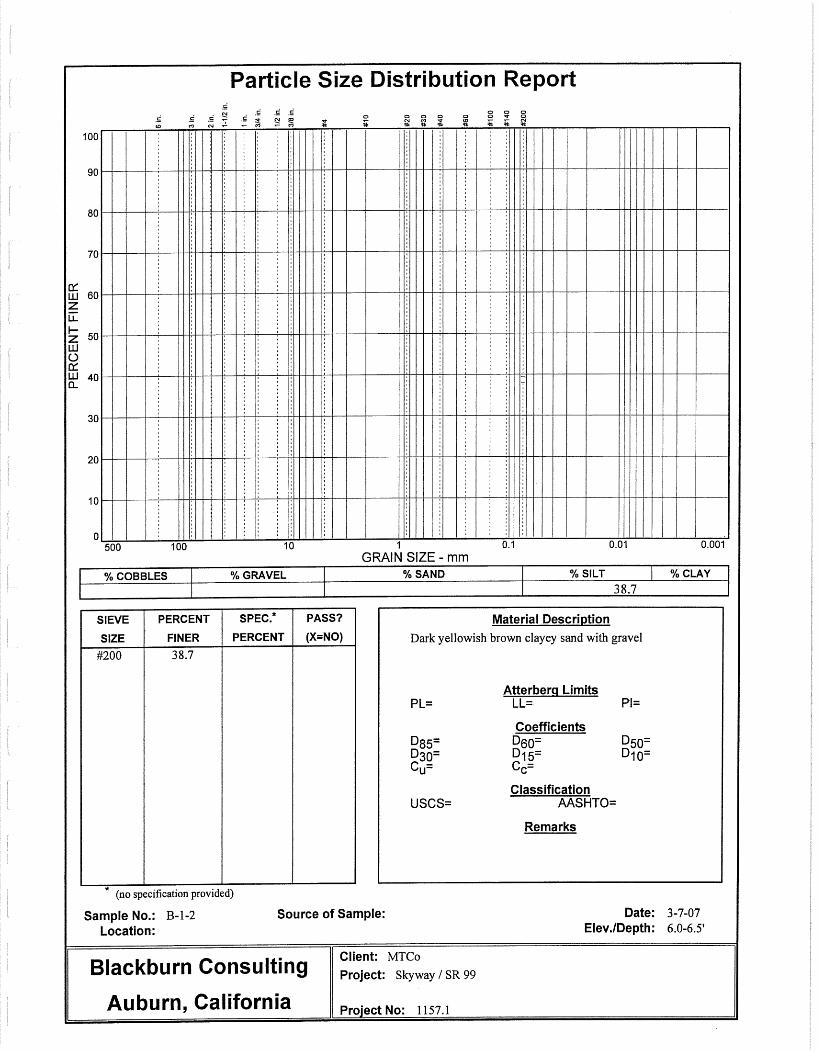
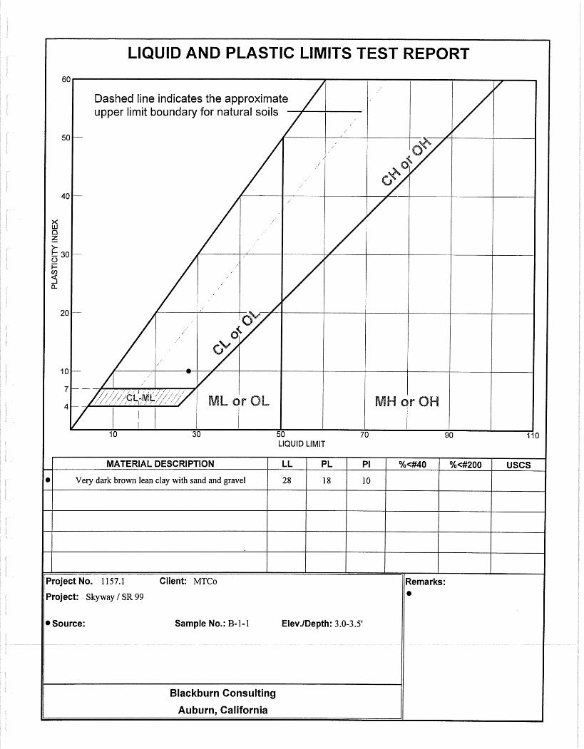
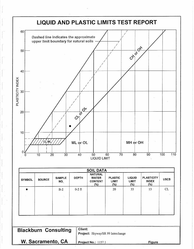
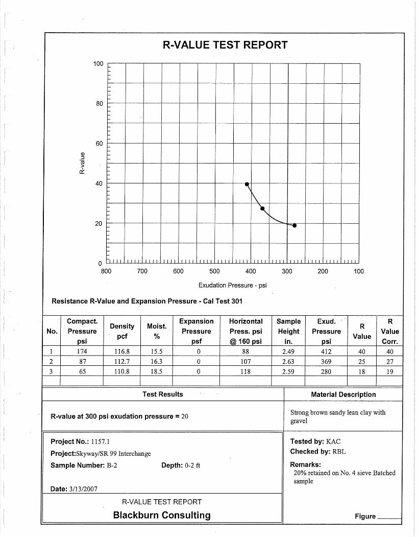
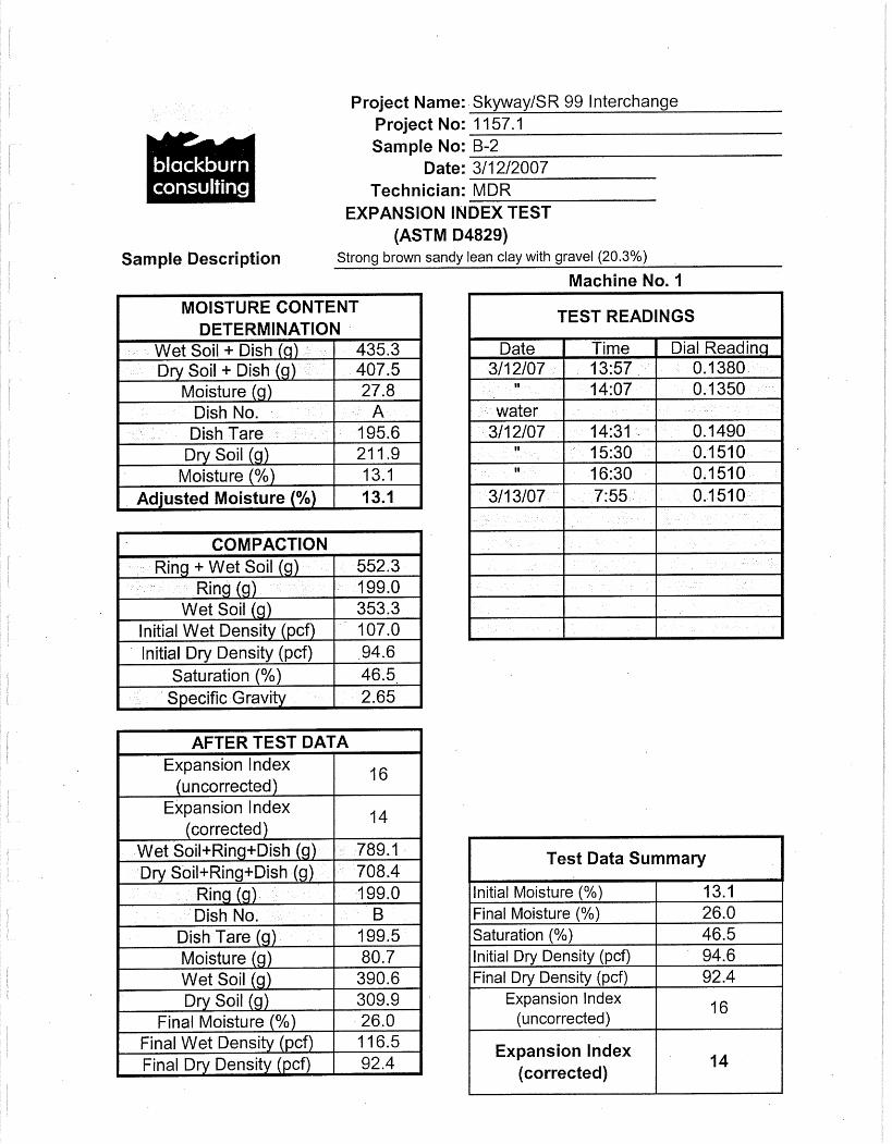
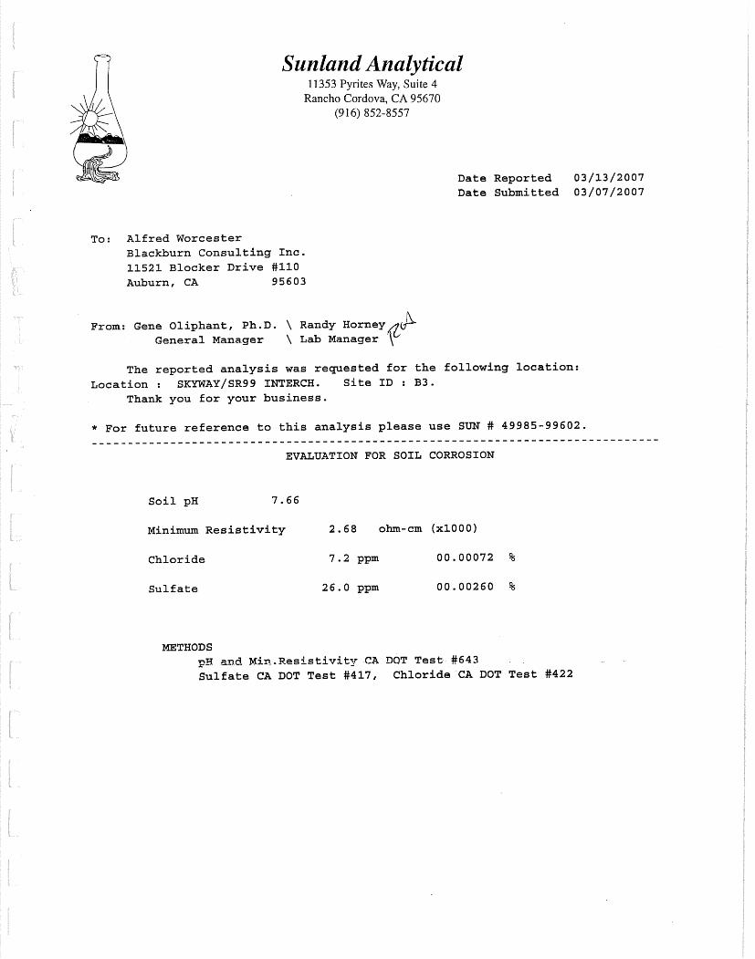
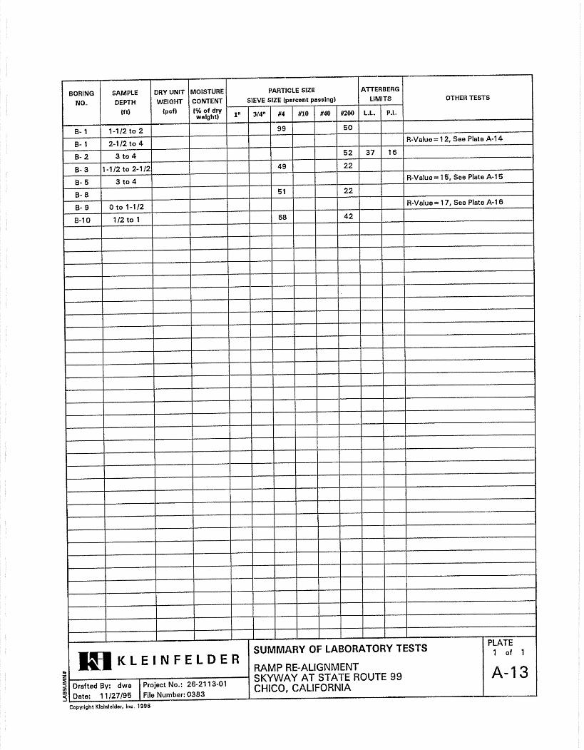
• Moisture/density determination for in-place soil characteristics. • Expansion Index for review of expansion potential. • R-Value for pavement design. • Atterberg Limits and Sieve analysis for confirmation of material type. • Resistivity, pH, and sulfate and chloride content for corrosion characteristics.
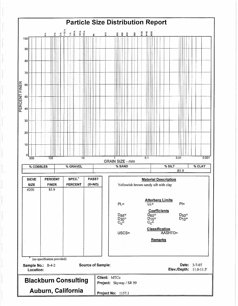
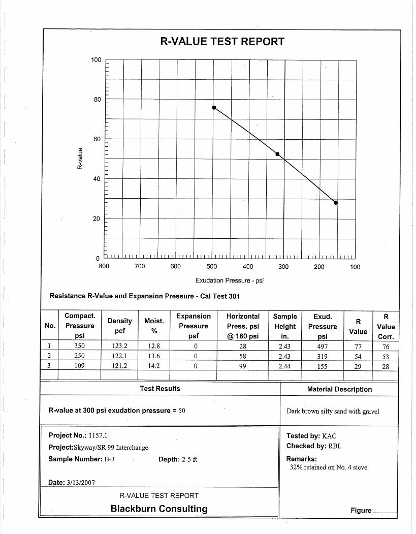
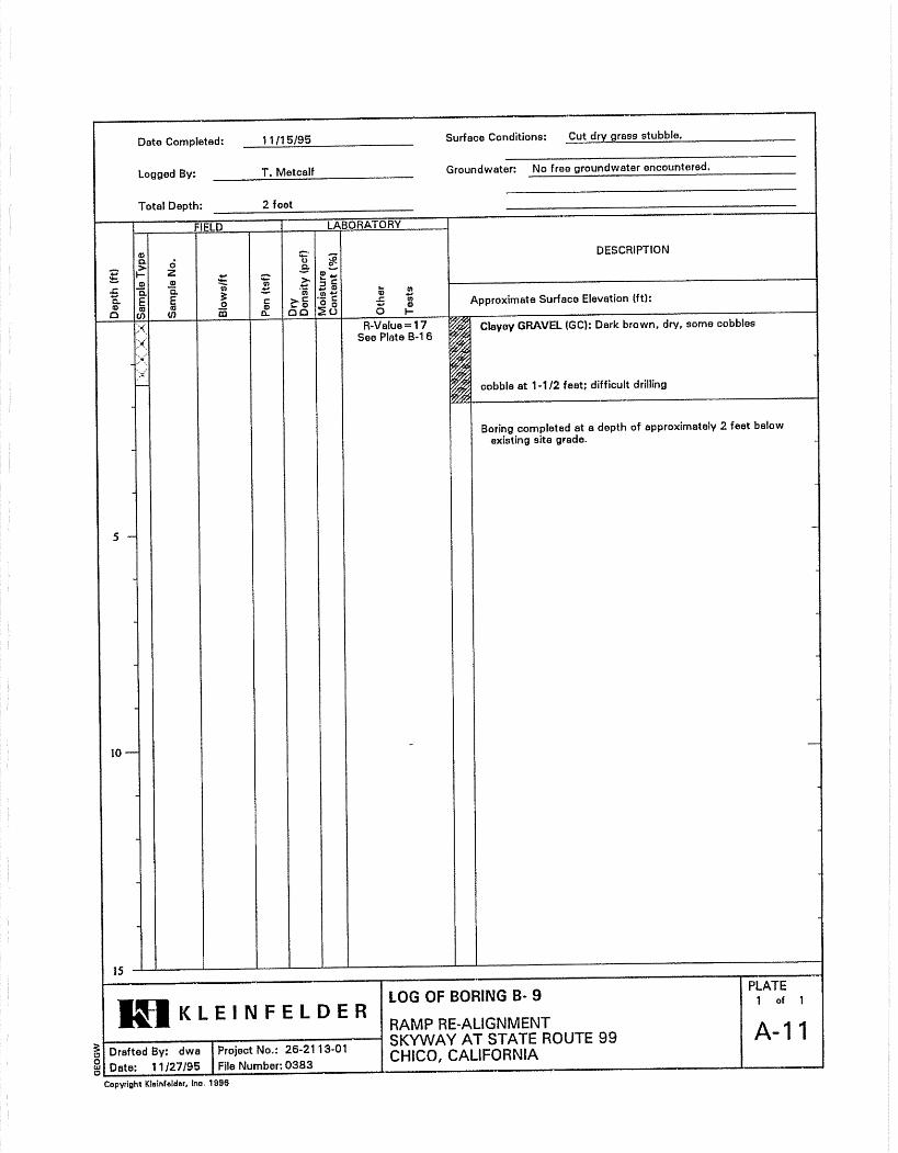
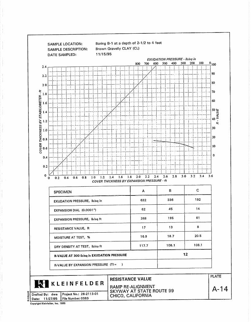
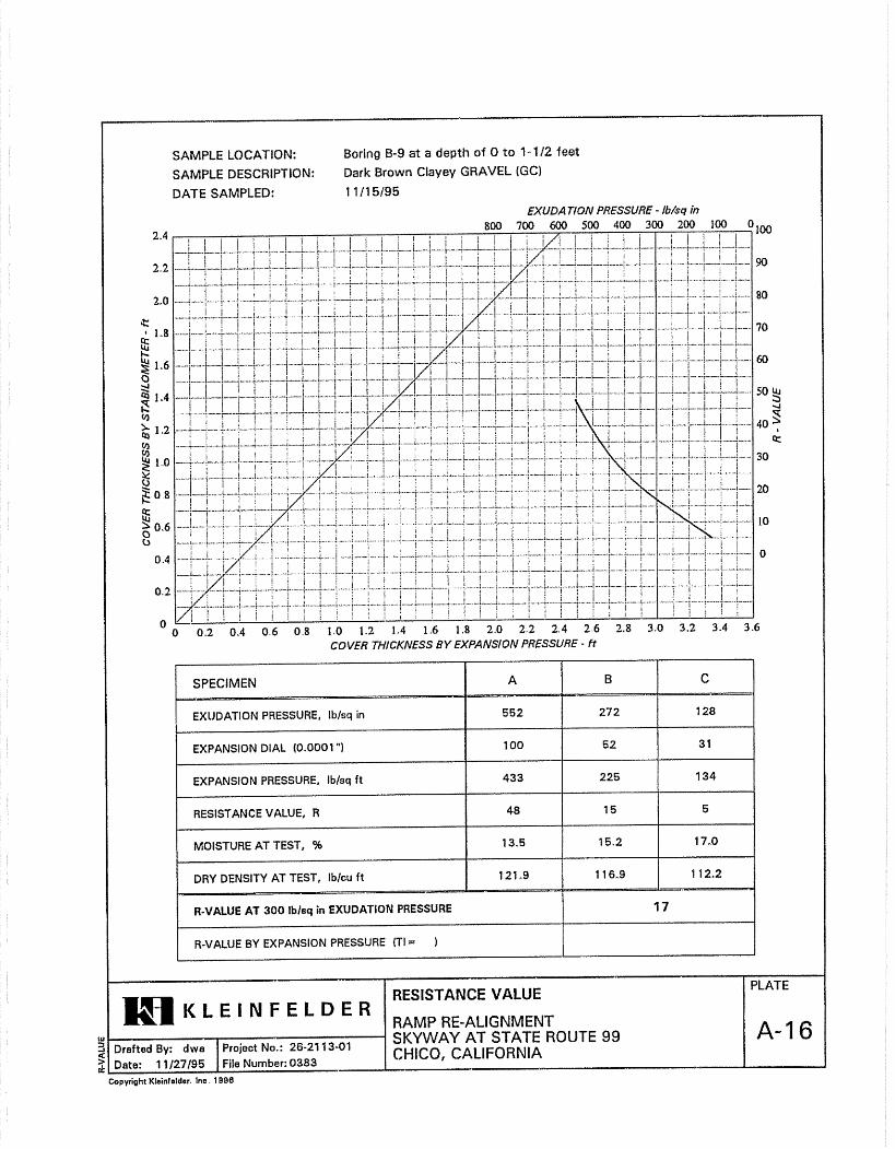
Moisture and density testing indicate that the dry unit weight of soil ranges from 78 pcf to 119 pcf and moisture content ranges from 4% to 41% of the dry density, and averaged 17 percent. We checked a bulk sample of clayey soil for expansion index and obtained a value of 14; a “low” expansion potential according to California Building Code. Two bulk samples indicated R-values of 20 and 50. Corrosion tests resulted in sulfate and chloride quantities of less than 7.2 to 26 parts per million, resistivity greater than 2,400 ohm-cm, and relatively neutral pH of 6.8 to 7.7. We provide test results on the boring logs where appropriate and in Appendix B.
Geotechnical Design/ Materials Report for the SR99 / Skyway BCI No. 1157.1 Interchange Project– Phase 2, Chico, California June 28, 2007
4
GEOTECHNICAL CONDITIONS
Site Geology Published geologic mapping1 shows the site as underlain by the Pleistocene-age Red Bluff Formation and older volcanic mudflow deposits of the Tuscan Formation. The Red Bluff Formation typically consists of fine to coarse gravel in a red clay and silt matrix, with minor amounts of inner bedded sand and silt. The Red Bluff Formation unconformably overlies the Tuscan Formation at a depth of about 40 feet below ground surface.
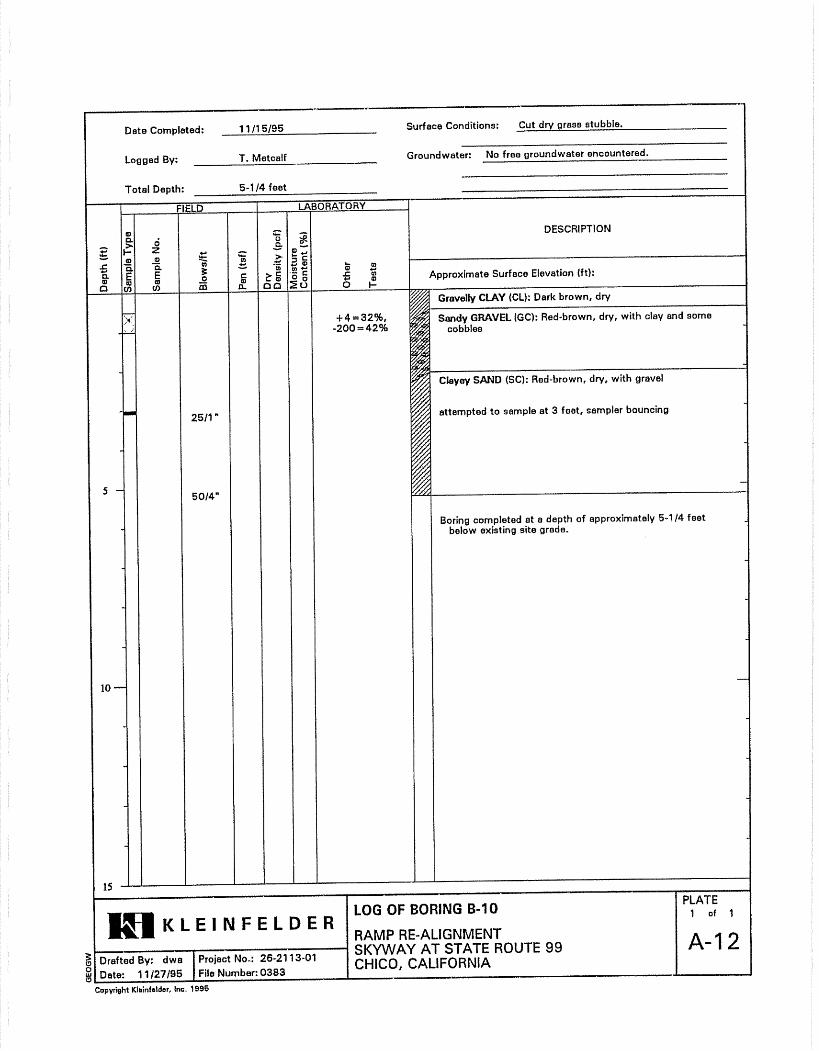
Geotechnical Conditions - Soil Within the interchange area and west, our subsurface investigation revealed that layers of silty, clayey gravel and gravelly clay and silt are present beneath the site. Boring B-1 encountered stiff to hard clay, silt and clayey sand from the surface to 8 feet bgs. These materials are underlain by dense, silty gravel to the total depth of 12 ft bgs. B-2 encountered medium dense to dense clayey and silty gravel as fill to 8 feet bgs. Very dense, poorly graded gravel underlies the upper materials to a depth of 11.5 ft bgs. East of the interchange, our borings encountered predominately loose to very dense, sandy and silty gravel, and very stiff to hard sandy silt (B-3, B-4). The ten (10) Phase 1 borings advanced at the interchange (Kleinfelder, 2000) encountered similar subsurface materials, with predominately stiff to hard, gravelly clay and very dense, clayey gravel from the surface to 10 feet bgs. The above descriptions are general. Refer to the Log of Test Borings in Appendix B for more specific soil descriptions, laboratory test results, and blow count data.
Geotechnical Conditions - Groundwater We did not observe groundwater in any of the four borings advanced to 12-feet bgs. The borings advanced for Phase 1 of the project (Kleinfelder, 2000) also did not encounter groundwater to the maximum depth drilled of 10 feet bgs. Based on the observed subsurface lithology and the presence of an active drainage along the west side of Carmichael Drive, perched water conditions are possible within the project area. Based on our experience in the area, groundwater can occur at isolated locations within the subsurface. An accumulation of water may occur near the interface between permeable gravels and relatively impermeable silt/clay zones, following rainy periods.
Project Site Seismicity We do not expect ground rupture and/or fault creep to occur at the site; however, some level of ground motion will occur from seismic activity in the region.
1 Suacedo, GL and Wagner, DL, 1992, Geologic Map of the Chico, California, California Division of Mines and Geology, Regional Geologic Map Series.
Geotechnical Design/ Materials Report for the SR99 / Skyway BCI No. 1157.1 Interchange Project– Phase 2, Chico, California June 28, 2007
5
Ground Motion Based on published geologic maps and the State of California, Department of Transportation, Caltrans Seismic Hazard Map2, the controlling fault for design is the Big Bend Fault located approximately 13.7 miles east of the site. This is a normal style fault with an estimated maximum Magnitude of 6.5. The horizontal Peak Bedrock Acceleration (PBA) at the site is 0.15g.
Ground Rupture The Fault Activity Map of California and Adjacent Areas3 does not identify any active or potentially active faults crossing this site. The site does not lie within or adjacent to an Alquist–Priolo Earthquake Fault Zone4. Our review of published geologic mapping and preliminary site review did not reveal the presence of Late Quaternary (displacement within the last 700,000 years) or younger faults within the project site. Therefore, the potential for ground rupture at the site is low.
Liquefaction Liquefaction can occur when loose to medium dense, granular, saturated soils (generally within 50 feet of the surface) are subject to ground shaking. Based on our investigation, low to non-liquefiable, very dense clayey silty gravel underlie the project site. We consider these materials to have a very low potential for liquefaction.
GEOTECHNICAL ANALYSIS AND DESIGN
Cuts and Excavations
Clearing and Ground Preparation Prior to making cuts and fills, remove any debris or loose soil, strip vegetation to a minimum depth of 4 inches below the ground surface, and remove brush and trees including roots greater than 2 inches in diameter. Do not use strippings within engineered fill. Place strippings in landscape areas (if approved by the designer) or remove from the site. Conduct all clearing and grubbing in accordance with Section 16 of the latest Caltrans Standard Specifications. Prior to placing fill on stripped or overexcavated ground surfaces, scarify the ground surface to a minimum depth of 8 inches, in accordance with Section 19 of the Caltrans Standard Earthwork Specifications (CSES). Moisture-condition the scarified soil to within 3% of optimum and compact it to a minimum of 95% relative compaction based on Caltrans test procedures. Scarification and recompaction may be waived where the subgrade consists of hard, dense, undisturbed and unyielding ground, as verified by proof rolling. 2 Lalliana Mualchin, 1996, California Seismic Hazard Map, State of California Department of Transportation. 3 Jennings, Charles, 1994, Fault Activity Map of California and Adjacent Areas, 1:750,000; California Division of Mines and Geology, Geologic Data Map No. 6. 4 Hart, E.W., Bryant, 1997, Fault Rupture Hazard Zones in California; California Division of Mines and Geology, Special Publication 42
Geotechnical Design/ Materials Report for the SR99 / Skyway BCI No. 1157.1 Interchange Project– Phase 2, Chico, California June 28, 2007
6
All excavations shall conform to Section 19-2 of the CSES. Construct all temporary cuts or trenches no steeper than 1:1. Remove all soft subgrade from existing ditches and replace with material compacted to 90% relative compaction.
Compaction On-site soil is suitable for use as engineered fill, if it is moisture conditioned and free of organics and debris. Grading will consist of reconstructing 5 to 15 foot high embankment ramps with fill derived from the existing ramps proposed for removal, or from other borrow areas not yet identified. Perform all grading and earthwork in accordance with Section 19 of the CSES. Place fill in horizontal lifts with a maximum loose lift thickness of 8 inches (excluding gravel larger than 3 inches). Structural fill shall be moisture-conditioned to within 3% of optimum and compacted to a minimum of 95% relative compaction based on Caltrans test procedures. The upper 3 feet of fill shall not contain gravel larger than 3 inches in greatest dimension. Compact material greater than 3 inches in dimension at depths of 3 feet or more below finish grade. Place and compact rocky fill materials in accordance with the CSES, Section 109-5.02. Existing asphalt-concrete pavement sections may be reused as structural fill, if it is broken up to meet these fill and compaction specifications. Thoroughly mix soil and rocky materials (broken asphalt) to prevent nesting and voids.
Soil Rippability Based on the observed soil conditions, we estimate generally normal excavation conditions to depths of 5 feet using conventional grading equipment. Very dense gravels and small cobbles are intermittently present throughout the subsurface, and present a moderate challenge to excavating and grading equipment. We expect generally good grading conditions during the later summer and fall. We anticipate shallow, perched groundwater throughout the subsurface of the project site if grading and excavating is performed during the rainy season.
Embankments Construct all fill slopes at a gradient no steeper than 2h:1v (horizontal to vertical). To achieve adequate compaction on the face of fill slopes, overbuild the slopes and then cut back to the design grade. Track walking is not an adequate method to compact the face of the slope. For widening of existing embankments, clear and grub the existing embankment surfaces and bench into the fill slopes in accordance with the CSES. Import borrow sources are not yet identified and, therefore, embankment materials cannot be evaluated. However, we expect slopes constructed at gradients of 2h:1h or flatter to be grossly stable when constructed with approved materials and in accordance with the CSES. Provide erosion control measures on slopes in accordance with Section 20 of the CSES.
Geotechnical Design/ Materials Report for the SR99 / Skyway BCI No. 1157.1 Interchange Project– Phase 2, Chico, California June 28, 2007
7
Settlement We anticipate immediate settlement of the embankment foundation materials. The native foundation subgrade is composed of a mixture of firm to hard cohesive material and loose to dense, granular materials. We expect these materials will settle about ¾ to 1½ inches, substantially occurring during construction. We recommend a waiting period of two to three weeks between placement of all embankments to the finished subgrade elevation and the placement of pavement structural sections.
Roadway Construction
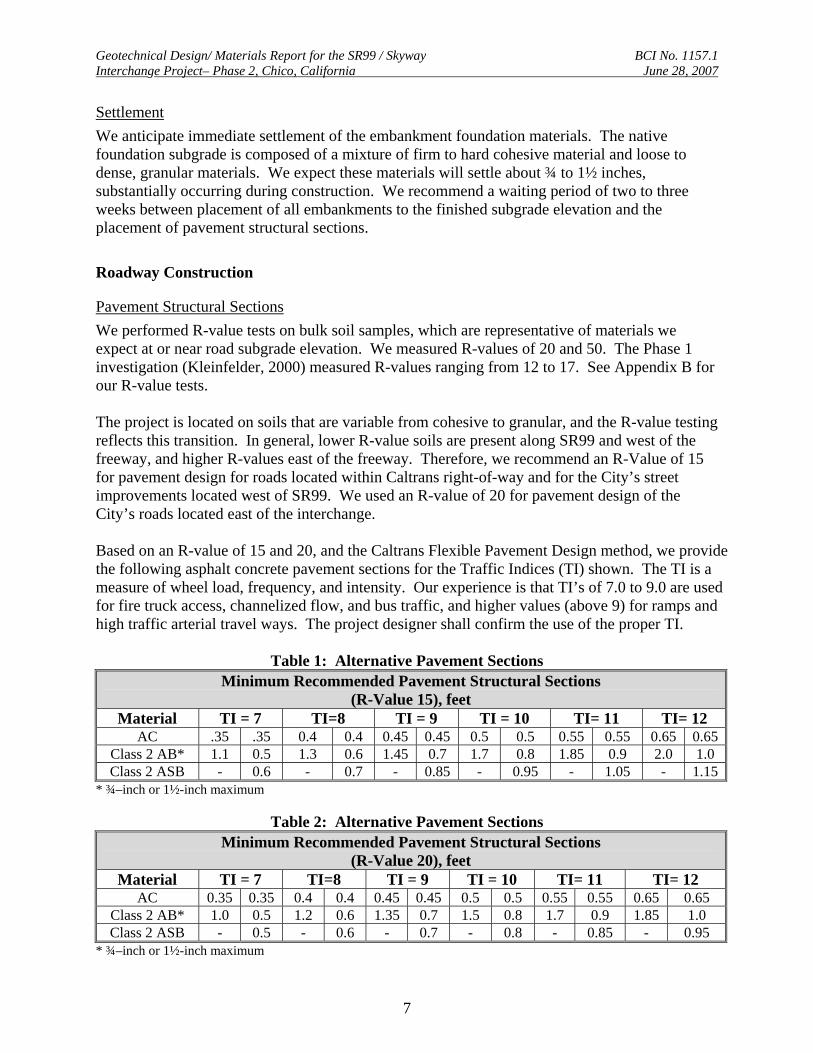
Pavement Structural Sections We performed R-value tests on bulk soil samples, which are representative of materials we expect at or near road subgrade elevation. We measured R-values of 20 and 50. The Phase 1 investigation (Kleinfelder, 2000) measured R-values ranging from 12 to 17. See Appendix B for our R-value tests. The project is located on soils that are variable from cohesive to granular, and the R-value testing reflects this transition. In general, lower R-value soils are present along SR99 and west of the freeway, and higher R-values east of the freeway. Therefore, we recommend an R-Value of 15 for pavement design for roads located within Caltrans right-of-way and for the City’s street improvements located west of SR99. We used an R-value of 20 for pavement design of the City’s roads located east of the interchange. Based on an R-value of 15 and 20, and the Caltrans Flexible Pavement Design method, we provide the following asphalt concrete pavement sections for the Traffic Indices (TI) shown. The TI is a measure of wheel load, frequency, and intensity. Our experience is that TI’s of 7.0 to 9.0 are used for fire truck access, channelized flow, and bus traffic, and higher values (above 9) for ramps and high traffic arterial travel ways. The project designer shall confirm the use of the proper TI.
Table 1: Alternative Pavement Sections Minimum Recommended Pavement Structural Sections
(R-Value 15), feet Material TI = 7 TI=8 TI = 9 TI = 10 TI= 11 TI= 12
AC .35 .35 0.4 0.4 0.45 0.45 0.5 0.5 0.55 0.55 0.65 0.65Class 2 AB* 1.1 0.5 1.3 0.6 1.45 0.7 1.7 0.8 1.85 0.9 2.0 1.0 Class 2 ASB - 0.6 - 0.7 - 0.85 - 0.95 - 1.05 - 1.15
* ¾–inch or 1½-inch maximum
Table 2: Alternative Pavement Sections Minimum Recommended Pavement Structural Sections
(R-Value 20), feet Material TI = 7 TI=8 TI = 9 TI = 10 TI= 11 TI= 12
AC 0.35 0.35 0.4 0.4 0.45 0.45 0.5 0.5 0.55 0.55 0.65 0.65 Class 2 AB* 1.0 0.5 1.2 0.6 1.35 0.7 1.5 0.8 1.7 0.9 1.85 1.0 Class 2 ASB - 0.5 - 0.6 - 0.7 - 0.8 - 0.85 - 0.95
* ¾–inch or 1½-inch maximum
Geotechnical Design/ Materials Report for the SR99 / Skyway BCI No. 1157.1 Interchange Project– Phase 2, Chico, California June 28, 2007
8
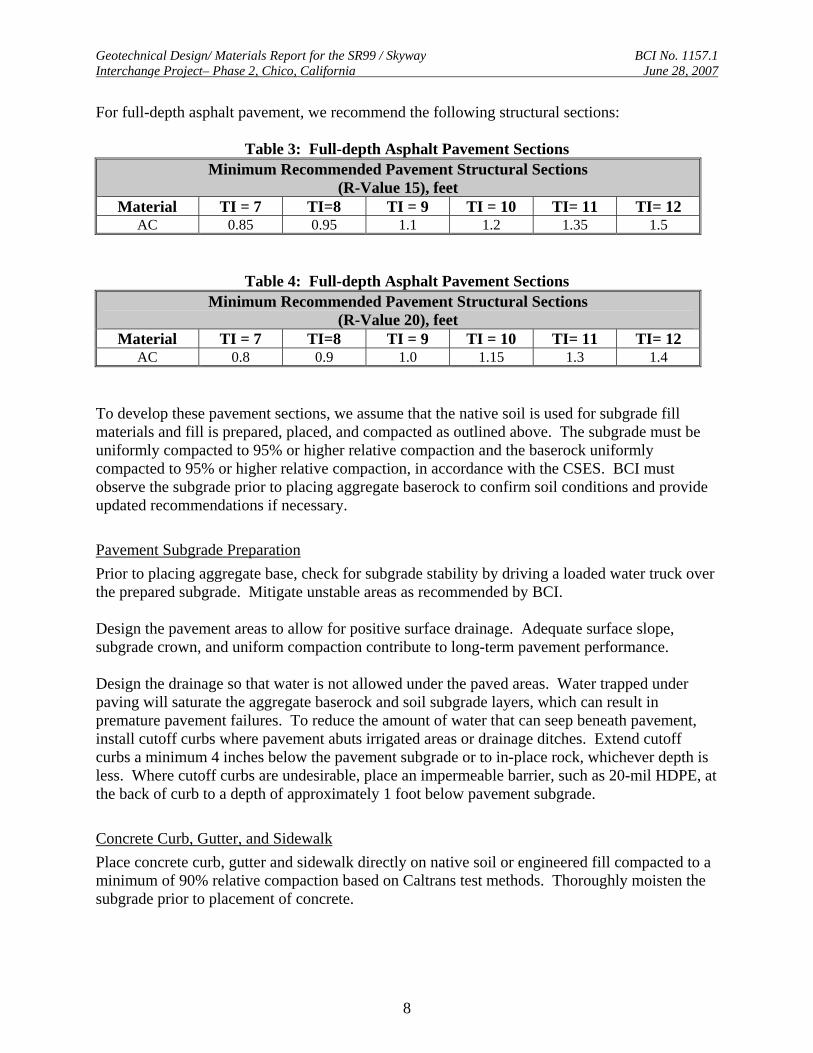
For full-depth asphalt pavement, we recommend the following structural sections:
Table 3: Full-depth Asphalt Pavement Sections Minimum Recommended Pavement Structural Sections
(R-Value 15), feet Material TI = 7 TI=8 TI = 9 TI = 10 TI= 11 TI= 12
AC 0.85 0.95 1.1 1.2 1.35 1.5
Table 4: Full-depth Asphalt Pavement Sections Minimum Recommended Pavement Structural Sections
(R-Value 20), feet Material TI = 7 TI=8 TI = 9 TI = 10 TI= 11 TI= 12
AC 0.8 0.9 1.0 1.15 1.3 1.4 To develop these pavement sections, we assume that the native soil is used for subgrade fill materials and fill is prepared, placed, and compacted as outlined above. The subgrade must be uniformly compacted to 95% or higher relative compaction and the baserock uniformly compacted to 95% or higher relative compaction, in accordance with the CSES. BCI must observe the subgrade prior to placing aggregate baserock to confirm soil conditions and provide updated recommendations if necessary.
Pavement Subgrade Preparation Prior to placing aggregate base, check for subgrade stability by driving a loaded water truck over the prepared subgrade. Mitigate unstable areas as recommended by BCI. Design the pavement areas to allow for positive surface drainage. Adequate surface slope, subgrade crown, and uniform compaction contribute to long-term pavement performance. Design the drainage so that water is not allowed under the paved areas. Water trapped under paving will saturate the aggregate baserock and soil subgrade layers, which can result in premature pavement failures. To reduce the amount of water that can seep beneath pavement, install cutoff curbs where pavement abuts irrigated areas or drainage ditches. Extend cutoff curbs a minimum 4 inches below the pavement subgrade or to in-place rock, whichever depth is less. Where cutoff curbs are undesirable, place an impermeable barrier, such as 20-mil HDPE, at the back of curb to a depth of approximately 1 foot below pavement subgrade.
Concrete Curb, Gutter, and Sidewalk Place concrete curb, gutter and sidewalk directly on native soil or engineered fill compacted to a minimum of 90% relative compaction based on Caltrans test methods. Thoroughly moisten the subgrade prior to placement of concrete.
Geotechnical Design/ Materials Report for the SR99 / Skyway BCI No. 1157.1 Interchange Project– Phase 2, Chico, California June 28, 2007
9
Culverts Shallow native soils and embankment fills (constructed in accordance with CSES) are suitable for culvert placement when designed and placed in accordance with the Highway Design Manual, Standard Plans, and the CSES.
Corrosion For structural elements, Caltrans5 considers a site corrosive if one or more of the following conditions exist for the representative soil and/or water samples taken at a site:
• Chloride concentration is 500 parts per million (ppm) or greater, • Sulfate concentration is 2000 ppm or greater, • pH is 5.5 or less.
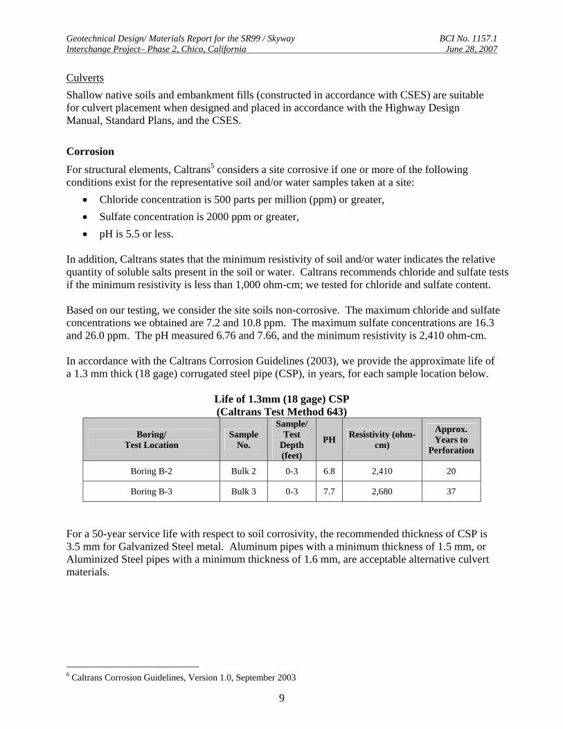
In addition, Caltrans states that the minimum resistivity of soil and/or water indicates the relative quantity of soluble salts present in the soil or water. Caltrans recommends chloride and sulfate tests if the minimum resistivity is less than 1,000 ohm-cm; we tested for chloride and sulfate content. Based on our testing, we consider the site soils non-corrosive. The maximum chloride and sulfate concentrations we obtained are 7.2 and 10.8 ppm. The maximum sulfate concentrations are 16.3 and 26.0 ppm. The pH measured 6.76 and 7.66, and the minimum resistivity is 2,410 ohm-cm. In accordance with the Caltrans Corrosion Guidelines (2003), we provide the approximate life of a 1.3 mm thick (18 gage) corrugated steel pipe (CSP), in years, for each sample location below.
Life of 1.3mm (18 gage) CSP (Caltrans Test Method 643)
Boring/ Test Location
Sample No.
Sample/ Test
Depth (feet)
PH Resistivity (ohm-cm)
Approx. Years to
Perforation
Boring B-2 Bulk 2 0-3 6.8 2,410 20
Boring B-3 Bulk 3 0-3 7.7 2,680 37
For a 50-year service life with respect to soil corrosivity, the recommended thickness of CSP is 3.5 mm for Galvanized Steel metal. Aluminum pipes with a minimum thickness of 1.5 mm, or Aluminized Steel pipes with a minimum thickness of 1.6 mm, are acceptable alternative culvert materials.
6 Caltrans Corrosion Guidelines, Version 1.0, September 2003
Geotechnical Design/ Materials Report for the SR99 / Skyway BCI No. 1157.1 Interchange Project– Phase 2, Chico, California June 28, 2007
10
CONSTRUCTION CONSIDERATIONS
Perched Groundwater and Over-optimum Soil Moisture Perched groundwater may be encountered during and shortly following the rainy season within shallow soils. If perched groundwater or surface water is encountered, sump pumps may be required to facilitate construction. Excessively over-optimum (wet) soil conditions can make proper compaction difficult or impossible. Wet soil is commonly encountered during the winter and spring months, or in excavations where groundwater or perched groundwater is encountered. In general, mitigate wet soils by:
• Discing the soil during prolonged periods of dry weather • Overexcavating and replacement with drier material • Lime/cement treatment or stabilization using aggregate and or stabilization fabric
Contact BCI for specific recommendations during construction. RISK MANAGEMENT Our experience and that of our profession clearly indicates that the risks of costly design, construction, and maintenance problems can be significantly lowered by retaining the geotechnical engineer of record to provide additional services during design and construction. For this project, retain BCI to:
• Review and provide comments on the civil plans, foundation plans, and specifications prior to construction.
• Monitor construction to check and document our report assumptions. At a minimum, BCI should monitor grading, cut slope excavation, and the placement and compaction of pavement subgrade, aggregate baserock, and asphalt-concrete.
• Update this report if design changes occur, if 2 or more years lapse between the date of this report and construction, and/or if site conditions have changed.

Geotechnical Design/ Materials Report for the SR99 / Skyway BCI No. 1157.1 Interchange Project– Phase 2, Chico, California June 28, 2007
11
LIMITATIONS BCI performed services in accordance with generally accepted geotechnical engineering principles and practices currently used in this area. Where referenced, we used ASTM or Caltrans standards as a general (not strict) guideline only. We do not warranty our services. BCI based this report on the current site conditions. We assumed the soil, rock and ground water conditions are representative of the subsurface conditions on the site. Actual conditions between test pits could be different. Differing conditions could result in higher costs. Our scope did not include evaluation of hazardous materials, site geology, site seismicity, flooding potential, aerial photograph review, toxicology, or soil corrosion potential. See the Appendix for Logs of our test pits. The lines designating the interface between soil types are approximate. The transition between soil/rock types may be abrupt or gradual. Our recommendations are based on the final logs, which represent our interpretation of the field logs and general knowledge of the site and geological conditions. Groundwater levels could differ from those discussed in our report. Modern design and construction are complex, with many regulatory sources/restrictions, involved parties, construction alternatives, etc. It is common to experience changes and delays. The owner should set aside a reasonable contingency fund based on complexities and cost estimates to cover changes and delays. Only use this report for design and construction of this project.