state of the art for long span prestressed concrete bridges of segmental construction ·...
TRANSCRIPT

STATE OF THE ART FORLONG SPAN PRESTRESSEDCONCRETE BRIDGES OFSEGMENTAL CONSTRUCTION
Segmental prestressed concrete bridges are described in termsof cross-sectional shape, layout of tendons, casting procedures, jointingtechniques, and design details. Techniques of analysis forstructures of this type are reviewed. Prospects for use of thistype of construction in the United States are discussed and currentwork outlined.
Geoffrey C. Lacey John E. BreenUniversity of New South Wales The University of TexasSydney, Australia Austin, Texas
Ned H. BurnsThe University of TexasAustin, Texas
In highway bridge constructionthere is an increasing trend towardthe use of longer spans. This trend isthe result of a number of differentrequirements relating to safety,economy, function and esthetics. .
The February 1967 report(38> ofthe special AASHO Traffic SafetyCommittee calls for the "adoptionand use of two-span bridges for over-passes crossing divided highways .. .to eliminate the bridge piers normal-ly placed adjacent to the outsideshoulders." To comply with thesesafety criteria, two-span, three-span,and four-span overpasses will be re-quired with spans up to 180 ft.(55 m).
In the case of elevated urban ex-pressways, long spans will facilitate
September-October 1971
access and minimize obstruction.With stream crossings, even longerspans in the 300 ft. (90 m) range willsometimes be necessary. When allfactors are considered the trend to-ward long span bridges seems irre-versible.
Precast I-girders, of the type nowwidely used for spans up to 120 ft.(37 m), will not be adequate forthese longer spans. It was pro-posed(48) that AASHO Type VII-girders might be used for simplespans up to 140 ft. (43 m) and con-tinuous spans up to 160 ft. (49 m)(where precast lengths of 80 ft. arejoined together by splicing). To ob-tain greater spans than this, the useof haunched sections or inclinedpiers was also proposed.
53

Table 1. Segmental precast, post-tensioned box girder bridges
Bridge and Location YearSpans
ft.No. ofBoxes
CellsPerBox
bft.
b'ft.
AustraliaSilverwater Bridge, Sydney 1962 120-20 -120 2 1 — —Commonwealth Avenue Bridge, 1963 185-210-240-210-185 1 3 40 40CanberraTaren Point Bridge, Sydney 1964 2 @ 235-250-2 @ 235 4 1 21 11AustriaTraun Bridge, Linz 1961 246-30 -246 4 1 22 7.9Ager Bridge 1963 238-278-278-117 1 1 46 17.7CanadaLievre River Bridge, Quebec 1967 130-26 -130 1 2 33 22CzechoslovakiaOndava Bridge, Sirnik 1964 98-197-98 2 1 18 7.9Kosicke Hamre Bridge 1965 126-25 -126 — -Railway Bridge, Margecany 1966 100-180-100 1 1 18.4 -EnglandHammersmith Flyover, London 1961 11 @ 140 1 3 61 10
Mancunian Way, Manchester 1966 28 @ 105 1 1 30 9Western Avenue Viaduct,
1968 [Several @ 115 (approx.) 1 3 62 —London 1Several @ 204 (approx.) 1 3 94 -FranceChoisy-Le-Roi Bridge, Paris 1965 123-180-123 2 1 22 12Bridge on the Rhone at 1184-276-184 — 2 1 27 11.5Pierre Benite 1965 164-246-246-164Oleron Viaduct 1965 26 @ 259 1 1 35 18Courbevoie Bridge, Paris 1966 131-197-131 4 1 29 -St. Denis Viaduct, Paris 1966 6 @ 157 2 2 47 23.1Pont Aval, Paris 1967 221-301-267-234 2 1 26 11.5JapanKakio Viaduct 1964 69-3 @ 122 1 1 23 13.1Kamiosaki Viaduct 196 —88102-88—
{2 1 24 9.8
75-129-75Konoshima Bridge 1968 138-282-138 1 1 27 13.1Tama Bridge 1969 164-165-165-164 2 1 20 -
MexicoBridge in Veracruz State 1965 20-131-20 1 1 14 7
NetherlandsOosterschelde Bridge 1965 52 @ 312 1 1 39 22Hartelkanaal Bridge 1967 220-375-220 2 1 28
.PolandBridge near Bomberg 1966 59-141-59 — — — -
RussiaAutosawodbridg 1960 119-487-119 — — —Ojat Bridge 1961 105-210-105 — — —Irtysch Bridge 1961 361 3 — — -Schelnicha Bridge, Moscow 1964 198-420-198 — — 48 -Don Bridge, Rostow 1964 260-455-260 — — — -
VenezuelaCaroni Bridge — 157-4 @ 315-157 1 1 34 13.1
Notes: See Fig. 1 for dimension designations in columns 6 to 9.1. C3 = 3 in. concrete joint; E = epoxy joint; D = dry joint.2. FT = falsework trusses; F = falsework; FG = falsework girders;
C = cantilever construction; A = assembly on shore.54 PC[ Journal
L

Table 1. (Cont.)
Span/ Segment Joints' Erectiondepth Length Method2ratio
dmas. drain. Lft. ft. drain. ft. Support System and Special Features
- - - - C 3 F T Deck cast in place9 9 27 10 C 3 F Roller bearings on piers
- 10.5 24 9 C 3 F T Cantilever-suspendedҟspan system-box section and slab cast separately
13.4 13.4 23 13 C F14 14 22 30 C F
14.8 5.8 - 9.5 E C Bridge and segments are skewed
4.6 9.8 C 1.2 C Structure forms a 3-span frame with a10 -hinge in the middle-deck slab be-
- - - 9.8 C 1.2 C tween boxes cast separately13 7.1 25 9.8 C C
9 6.5 21 10 C 3 F Girders rigidly connected to columns-superstructure includes box sectionand "coathanger" units
4.3 4.3 25 7.5 C 3 F "Rotaflon" sliding bearings on columns5.5
10.255.5
10.252120
7.77.8
C 4C4
F GFG Sliding bearings on columns
Superstructure forms a portal with the8.2 8.2 22 8.2 E C piers and is simply supported on the
abutments14 11.8 23 9.8 E C Girders are made continuous with the
caissons14.8 8.2 - 10.8 E C Semirigid support from neoprene pads7.5 7.5 26 12.5 E C on the piers6.6 6.6 24 9.8 E F Deck slab projections cast separately
18 11.1 29 12.5 E C -bridgeҟis curved-simple supportfrom neoprene pads on the piers
6.0 6.0 20 10.6 C 14 F4.9 4.9 26 8.2 E C
14.1 6.6 - 9.8 E C8.8 8.8 19 11 E C
7.2 7.2 18 3 C C
19 7 - 42 C 16 C Girders continuous with piers-dow-elled expansion joints at span centers
17.3 4.9 - - - -
- - - 9.8 D C
- - - - C8 C- - - 7.2 D C- - - 10.7 C 0.8 C- - - 9.8 E C- - - 9.8 E C
18.4 18.4 17 - - A
September-October 1971ҟ 915

a
(a) SINGLE CELL BOX GIRDER
b
v \ I
(b) SINGLE CELL BOXES CONNECTED BY UPPER SLAB
b
ai
b'ҟJ( c ) TWO-CELL BOX GIRDER
Fig. 1. Types of segmental box girder cross sections
56ҟ PCI Journal

ASPHALT SURFACE
IN SITU EDGE BEAM
61-0
PRE(
TRANSVERSEPRESTRESSIIBARS
CAST ROAD SLABS
ESSING CABLES
Fig. 2. Hammersmith Flyover, London, England
A substantial number of long spanbridges have been constructedthroughout the world utilizing pre-stressed concrete box girders. Thistype results in a very compact struc-tural member, which combines highflexural strength with high torsionalstrength. The box girders may be ei-ther cast-in-place or precast in seg-ments. Their suitability for very longspans can be seen from the BendorfBridge in West Germany, which wascast-in-place and has a span of 682ft. (208 m). In the United States,cast-in-place box girder bridges arebeing widely used by the CaliforniaDivision of Highways, as well as byseveral other states; precast, segmen-tal box girder bridges are now underconstruction in Nova Scotia andTexas.
When construction of large num-bers of bridges is envisaged, as in a.highway department, precasting hasa number of advantages over cast-in-place construction:
1. Mass production of standard-ized girder units is possible,such as is presently done with.precast I-girders for shorterspans.
2. High quality control can be at-tained through plant produc-tion and inspection.
3. Greater economy of productionis possible by precasting girderunits at a plant rather thancasting them in place.
4. Speed of erection can be muchgreater which is very importantwhen construction interfereswith existing traffic and is par-
September-October 1971ҟ 57

58
ticularly critical in an urban en-vironment.
This paper will examine in detailone means of achieving long spans inbridge structures, namely, segmental
z precast box girder construction. Theo reason for casting short segments is
that box girders, unlike I-girderswhich have narrow width, cannot bereadily transported in long sections.In addition, the short units are suitedto fairly simple methods of assemblyand post-tensioning to form the com-pleted structure. The length andweight of the segments are chosen soas to be most suitable for transporta-tion and erection.
U-
+^. TYPES OF CROSS SECTION ANDE PRESTRESSING SYSTEMS
a)Dimensions and details of a num-
E ber of segmental, prestressed con-crete box girder bridges are sum-marized in Table 1 and the cross sec-tions of many of them are shown in
o Figs. 1 to 15. With the exception ofthe Hammersmith Flyover, the su-perstructures of these bridges gener-ally conform to three main types: 1.the single cell box girder; 2. a pair of
v single cell box girders connected byT a deck slab; 3. the multi-cell box
girder (see Fig. 1). The prestressingM systems used depend partly on thei^. type of cross section, the structural
system, and the method of construc-tion, but vary greatly from bridge tobridge. Several of the bridges in-cluded in Table 1 are described indetail in the following sections.
Hammersmith Flyover. The Ham-mersmithFlyover in London( l " 2 ' 6 ) isof unique construction (see Fig. 2).
° The main girder element is a three-cell hollow box, 26 ft. (7.9 m) wide,cast in segments 8 ft. 6 in. (2.6 m)long. These alternate with 1 ft. (0.3m) thick, precast cantilever "coathanger" sections 60 ft. (18.3 m) wide.
PCI Journal

0 ,.ҟ24.- 0,. ҟ24'- 0"
IN-SITU MEDIANSTRIP
Fig. 4. Mancunian Way, Manchester, England
The sections are joined by 3 in. (7.6cm) of cast-in-place concrete. Pre-cast concrete slabs form the deck ofthe structure. The cantilever sectionsact as diaphragms for the box girderand also support the outer deck slabunits. The girders are rigidly con-nected to their supporting columns,which in turn rest on roller bearingsat their bases.
The Gifford-Udall system is usedfor longitudinal prestressing.Stranded cables, Pk-in. (2.86 cm) indiameter, are arranged in four clus-ters of 16 each, one cluster on eitherside of each inner web of the girder.At midspan, each cluster passesthrough a 10-in. (25.4 cm) diameterduct in the lower flange. The cablesare arranged longitudinally in over-
lapping groups, each group passingthrough two successive spans andoverlapping the next group by onespan length (see Fig. 3). Both endsare anchored in the top flange of thebox girder after passing over a col-umn. The cables are kept in positionby steel saddles over the columnsand at points 25 ft. (7.6 m) on eitherside of midspan; cable profiles arelinear between saddles.
The girder segments over the col-umns are prestressed transverselythrough the top flange and are tiedto the columns with vertical pre-stressing.
Single cell box girders. The follow-ing bridges are of this type: Ager(Austria), Margecany (Czechoslova-
34.8'
Fig. 5. Oleron Viaduct, FranceSeptember-October 1971ҟ 59

Fig. 6. Superstructure of the Oosterschelde Bridge, Netherlands
kia), Mancunian Way (England), 01-eron (France), Kakio and Konoshima(Japan), Oosterschelde (Nether-lands), and Caroni (Venezuela).
The Mancunian Way, Manches-terM26'39 , comprises a pair of singlecell box girders, joined by a cast-in-place median strip (see Fig. 4). Theupper slab of each box is cantilev-ered to accommodate the roadwaywidth. The precast segments are 7 ft.3 in. (2.2 m) long, with 3-in. (7.6 cm)concrete joints between. The verticalwebs of the box girders are madethick enough to accommodate all the
prestressing cables. There are 16 ca-bles through each section with twolayers of four in each web. Eachspan contains two sets of cables,each set being two spans long, over-lapping the next set by one spanlength, and anchored near the quar-ter points of the spans. The girdersare supported by Rotaflon slidingbearings on the columns.
Oleron Viaduct in France(20,24.42)is a single cell box girder bridge,with the upper deck slab cantilev-ered out to a total width of 35 ft.(10.7 m) (see Fig. 5). The precast seg-
Fig. 7. Ager Bridge, Austria60ҟ PCI Journal
c.
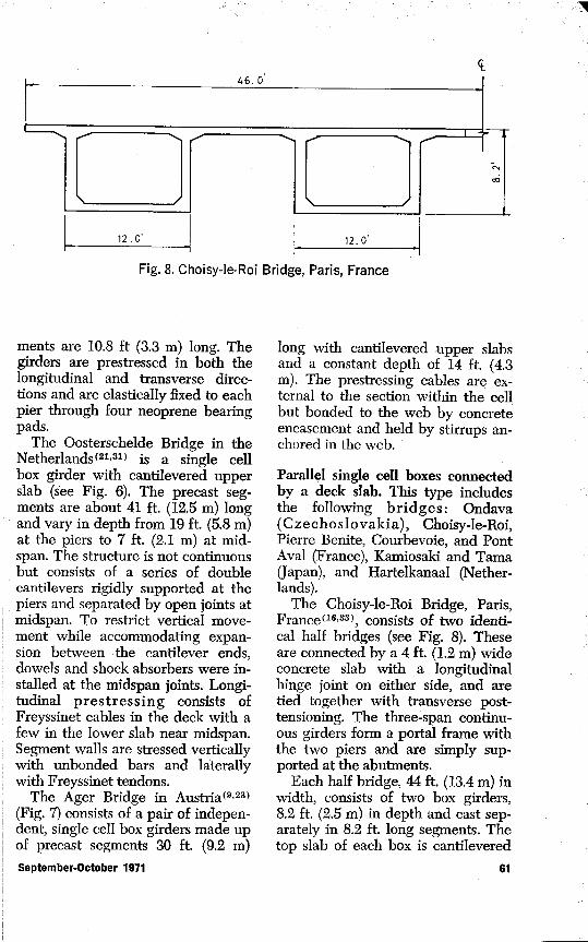
Fig. 8. Choisy-Ie-Roi Bridge, Paris, France
ments are 10.8 ft (3.3 m) long. Thegirders are prestressed in both thelongitudinal and transverse direc-tions and are elastically fixed to eachpier through four neoprene bearingpads.
The Oosterschelde Bridge in theNetherlands(21,31 ) is a single cellbox girder with cantilevered upperslab (see Fig. 6). The precast seg-ments are about 41 ft. (12.5 m) longand vary in depth from 19 ft. (5.8 m)at the piers to 7 ft. (2.1 m) at mid-span. The structure is not continuousbut consists of a series of doublecantilevers rigidly supported at thepiers and separated by open joints atmidspan. To restrict vertical move-ment while accommodating expan-sion between the cantilever ends,dowels and shock absorbers were in-stalled at the midspan joints. Longi-tudinal prestressing consists ofFreyssinet cables in the deck with afew in the lower slab near midspan.Segment walls are stressed verticallywith unbonded bars and laterallywith Freyssinet tendons.
The Ager Bridge in Austria(9,23)(Fig. 7) consists of a pair of indepen-dent, single cell box girders made upof precast segments 30 ft. (9.2 m)
long with cantilevered upper slabsand a constant depth of 14 ft. (4.3m). The prestressing cables are ex-ternal to the section within the cellbut bonded to the web by concreteencasement and held by stirrups an-chored in the web.
Parallel single cell boxes connectedby a deck slab. This type includesthe following bridges: Ondava(Czechoslovakia), Choisy-le-Roi,Pierre Benite, Courbevoie, and PontAval (France), Kamiosaki and Tama(Japan), and Hartelkanaal (Nether-lands).
The Choisy-le-Roi Bridge, Paris,France "16' 33 ), consists of two identi-cal half bridges (see Fig. 8). Theseare connected by a 4 ft. (1.2 m) wideconcrete slab with a longitudinalhinge joint on either side, and aretied together with transverse post-tensioning. The three-span continu-ous girders form a portal frame withthe two piers and are simply sup-ported at the abutments.
Each half bridge, 44 ft. (13.4 m) inwidth, consists of two box girders,8.2 ft. (2.5 m) in depth and cast sep-arately in 8.2 ft. long segments. Thetop slab of each box is cantilevered
September-October 1971ҟ 61

out in both directions. After erectionand longitudinal post-tensioning, thetwo girders are connected rigidlywith a concrete joint and transversepost-tensioning. At the piers the twobox girders are braced together witha transverse box, the vertical faces ofwhich also function as girder dia-phragms, one over each wall of theV-shaped pier. There are single dia-phragms at the abutments, both in-ternally and externally (i.e., betweenthe two box girders) but no interme-diate diaphragms.
There are two sets of longitudinalprestressing cables (see Fig. 9). Theprimary function of one set is towithstand the negative momentsduring construction (by the cantilev-er method). Some of these cables, ofvarying length, run horizontally inthe deck slab; the remainder havedraped profiles with anchorage inthe girder web. The second set ofcables is located in the lower slab forpositive moment near midspan withmost of them draped and anchoredin the deck slab.
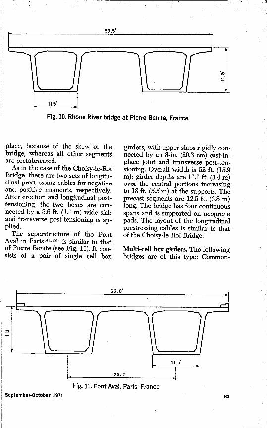
The bridge on the Rhone at PierreBenite( 34 > (Fig. 10) consists of a pairof single cell box girders with pro-jecting upper slabs, rigidly con-nected after erection. The depth is11.8 ft. (3.6 m), except near the sup-ports where it increases to approxi-mately 14 ft. (4.3 m). Each box is castin segments 9.8 ft. (3.0 m) long. Thesuperstructure is continuous over theintermediate supporting caissons, towhich it is rigidly connected, and itrests on neoprene pads at the abut-ments. Two diaphragms at each cais-son are extended to form a trans-verse box section bracing the twobox girders. There are single dia-phragms at the abutments but no in-termediate diaphragms. The girdersegments and the diaphragms at thecaissons and abutments are cast in
ao
m0
7.U,00
04-aD
w00C)
U
0
c
to
c
o;abU-
62ҟ PCI Journal
c . R,
Fig. 10. Rhone River bridge at Pierre Benite, France
place, because of the skew of thebridge, whereas all other segmentsare prefabricated.
As in the-case of the Choisy-le-RoiBridge, there are two sets of longitu-dinal prestressing cables for negativeand positive moments, respectively.After erection and longitudinal post-tensioning, the two boxes are con-
',' nected by a 3.6 ft. (1.1 m) wide slaband transverse post-tensioning is ap-plied.
The superstructure of the PontAval in Paris(41 '52 ) is similar to thatof Pierre Benite (see Fig. 11). It con-sists of a pair of single cell box
girders, with upper slabs rigidly con-nected by an 8-in. (20.3 cm) cast-in-place joint and transverse post-ten-sioning. Overall width is 52 ft. (15.9m); girder depths are 11.1 ft. (3.4 m)over the central portions increasingto 18 ft. (5.5 m) at the supports. Theprecast segments are 12.5 ft. (3.8 m)long. The bridge has four continuousspans and is supported on neoprenepads. The layout of the longitudinalprestressing cables is similar to thatof the Choisy-le-Roi Bridge.
Multi-cell box girders. The followingbridges are of this type: Common-
52.0'
mr _
11.5'
26.2'
Fig. 11. Pont Aval, Paris, FranceSeptember-October 1971 63

I
ING PANEL
4NDS
Fig. 12. Commonwealth Avenue Bridge, Canberra, Australia
wealth Avenue (Australia), Lievre(Canada), Western Avenue (En-gland), and St. Denis (France).
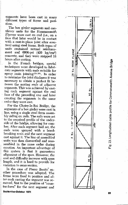
Commonwealth Avenue Bridge,Canberra, Australia( lo.11 >, is a three-cell box girder consisting of precastsegments 9 ft. (2.7 m) high, 10 ft. (3.0m) long, and 40 ft. (12.2 m) wide (seeFig. 12). Diaphragms are included atthe piers and near the third points ineach span, where a change in direc-tion of the longitudinal prestressingcables occurs. The girder is sup-ported on roller bearings seated onthe piers. The bridge is post-ten-sioned from end to end, using 1%-in.(2.86 cm) diameter tendons placedon either side of the four webs of thebox girders. The tendon profile isshown in Fig. 13. Vertical post-ten-sioning was applied to the webs ofthe box girder segments adjacent toand at the piers and transverse post-tensioning to all diaphragms.
The Western Avenue Viaduct inLondon(49 >, includes two differentwide, three-cell box girder bridges.
Both three-cell units, with projectingdeck slabs, were cast in full-widthsegments (see Fig. 14). One unit hasa width of 62 ft. (18.9 m) and thegirder spans approximately 115 ft.(35.0 m). The other unit is 94 ft. (28.7m) wide and is post-tensioned longi-tudinally, transversely and vertical-ly; the average girder span is 204 ft.(62 m). In both cases the continuoussuperstructure is seated on slidingbearings on the columns.
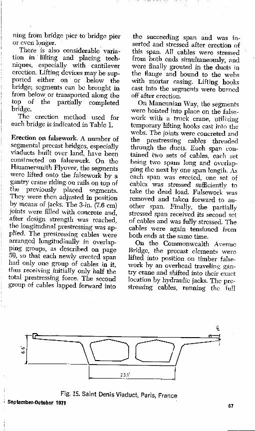
The St. Denis Viaduct, Paris,France(24 ), shown in Fig. 15, com-prises two half bridges, each a two-cell box girder with projecting deckslab.
METHODS OF PRECASTING
The methods of precasting usedwith segmental box girder bridgeswill be largely dependent on theprocedures selected for erection andjointing. General precasting advan-tages have been outlined by Ger-wick( 12 ). Precasting operations gen-erally follow normal procedures and
B4 PCI Journal
LL
za
LL
MCU-LLdz00C4
w0z
JU-
0
UI0z
I-U)
Izw
4)
v
`N
C
Co
C0EE0U
04-a,
0aa>
.Q0
CC
boC0Jn'r,
anL
segments have been cast in manydifferent types of forms and posi-tions.
The box girder segments and can-tilever units for the HammersmithFlyover were cast on end (i.e., on aface that later would be in contactwith a cast-in-place joint after erec-tion) using steel forms. Both types ofunits contained normal reinforce-ment and 6000-psi (420 kg/cm2)concrete, and they were stripped 18hours after casting.
In the French bridges, specialtechniques were developed to fabri-cate segments with ends suitable forepoxy resin jointing( 24 ,28). In orderto minimize the joint thickness it wasnecessary to obtain a perfect fit be-tween the mating ends of adjacentsegments. This was achieved by cast-ing each segment against the endface of the preceding one and latererecting the segments in the sameorder they were cast.
For the Choisy-le-Roi Bridge, thegse ments of a box girder were cast ing
line, using a single steel form assem-bly riding on rails. The rails were setto the required profile of the under-side of the bridge, allowing for cam-ber. After each segment had set, theends were sprayed with a bond-breaking resin and the next segmentcast against it. The line of assembledunits was then dismantled and reas-sembled in the same order duringerection. An important advantage ofthis system is that it guaranteesalignment of the span. However, thecost and difficulty increase with spanlength, and it is hard to provide forvariation in cross section.
In the case of Pierre Benite an-other procedure was adopted. Theforms were fixed in position and af-ter each casting the segment was re-
' moved, first to the position of "coun-ter-form" for the next segment andSeptember-October 1971ҟ 65

0I.' - 4••
UG
(a) 94-ft. WIDE SECTION.
62'- 0"
(b) 62-ft. WIDE SECTION
Fig. 14. Western Avenue Viaduct, London, England
then to storage. The form assemblyincluded an adjustment for variationin depth. With this procedure pre-cautions must be taken to ensureproper alignment of the fabricatedbridge girder. Pont Aval was fabri-cated in a similar manner with thealignment of each pair of segmentschecked on fabrication and any errorcompensated for in the next seg-ment. The segments for the St. DenisViaduct were cast on end instead ofin the normal horizontal position.
In all cases the ends of the websof the box girder segments werekeyed to prevent vertical slip before
setting of the epoxy. Generally, theflanges were also keyed.
ERECTION METHODS
Most of the bridges studied havebeen erected by one of the followingthree methods: 1. erection on false-work, 2. assembly on shore, and 3.the cantilever technique. There maybe considerable variation in eachmethod from bridge to bridge. Forexample, falsework may have shortspans with closely spaced supports,as in the case of a viaduct not pass-ing over existing roads, or may con-sist of large trusses or girders span-
66ҟ PCI Journal
ping from bridge pier to bridge pieror even longer.
There is also considerable varia-tion in lifting and placing tech-niques, especially with cantilevererection. Lifting devices may be sup-ported either on or below thebridge; . segments can be brought infrom below or transported along thetop of the partially completedbridge. .
The erection method used foreach bridge is indicated in Table 1.
Erection on falsework. A number ofsegmental precast bridges, especiallyviaducts built over land, have beenconstructed on falsework. On theHammersmith Flyover, the segmentswere lifted onto the falsework by agantry crane riding on rails on top ofthe previously placed segments.They were then adjusted in positionby means of jacks. The 3-in. (7.6 cm)joints were filled with concrete and,after design strength was reached,the longitudinal prestressing was ap-plied. The prestressing cables werearranged longitudinally in overlap-ping groups, as described on page59, so that each newly erected spanhad only one group of cables in it,thus receiving initially only half thetotal prestressing force. The secondgroup of cables lapped forward into
the succeeding span and was in-serted and stressed after erection ofthis span. All cables were stressedfrom both ends simultaneously, andwere finally grouted in the ducts inthe flange and bound to the webswith mortar casing. Lifting hookscast into the segments were burnedoff after erection.
On Mancunian Way, the segmentswere hoisted into place on the false-work with a truck crane, utilizingtemporary lifting hooks cast into thewebs. The joints were concreted andthe prestressing cables threadedthrough the ducts. Each span con-tained two sets of cables, each setbeing two spans long and overlap-ping the next by one span length. Aseach span was erected, one set ofcables was stressed sufficiently totake the dead load. Falsework wasremoved and taken forward to an-other span. Finally, the partiallystressed span received its second setof cables and was fully stressed. Thecables were again tensioned fromboth ends at the same time.
On the Commonwealth AvenueBridge, the precast elements werelifted into position on timber false-work by an overhead traveling gan-try crane and shifted into their exactlocation by hydraulic jacks. The pre-stressing cables, running the full
23.1'
Fig. 15. Saint Denis Viaduct, Paris, FranceSeptember-October 1971ҟ
67

length of the bridge, were tensionedfrom both ends. As the strandsstretched several feet during stress-ing, the load had to be applied instages, each stage being limited bythe stroke of the jack, anchored tem-porarily, and the jack moved for-ward and reset. After stressing, thecables were encased in concretebonded to the webs of the box gird-er.
In the case of the Western AvenueViaduct, a pair of large steel girders,longer than the bridge spans, wasmounted on steel falsework aroundthe columns. The tops of these gird-ers were set at the same height as thebottom of the box girder elements.Mobile cranes set the segments forone span on top of the steel girders,leaving 4-in. (10.2 cm) gaps betweensegments. After concreting of thejoints, the prestressing cables werethreaded through the ducts andpost-tensioned.
Movable falsework trusses havebeen used to construct bridges overwater. In the Silverwater( 3,12> andTaren Point(14,15 ) bridges in Austra-lia, the trusses were supported onledges at the piers. The segmentswere assembled on them, the 3-in.(7.6 cm) joints concreted, the pre-stressing cables placed and ten-sioned, and the trusses moved for-ward. A number of bridges in Japanhave been constructed over existinghighways using steel erection trussesto minimize interference with traffic.The trusses are set below, alongsideor above the bridge superstructure,depending on head-room require-ments.
Assembly on shore. Another methodof erection for river bridges is to as-semble the precast elements onfalsework on the shore. The jointsare then concreted and the prestress-ing applied. The assembled girders
may then be positioned by means ofbarges, as in the case of a number ofRussian bridges( 12 ), or by launchingover the piers, as on the CaroniBridge in Venezuela(5).
Cantilever construction. A numberof long-span bridges, especiallythose constructed over water, havebeen erected without falsework bythe cantilever technique(28.29 ). Thisinvolves placing the precast seg-ments, two at a time, symmetricallyon either side of a pier. Resistanceagainst the increasing negativebending moment is provided at eachstage of construction by adding pre-stressing cables of increasing lengthin the top chord of the girder. Thepier must be designed for possibleunbalanced moment loadings or sup-plemental struts or ties may be pro-vided.
In the case of the Choisy-le-RoiBridge, the segments were trans-ported by water and lifted into placewith a floating crane. Steel jigs setinside the cantilever arms were usedfor exact positioning. As each pair ofsegments was placed, the prestress-ing cables were threaded throughthe ducts, the abutting faces werecoated with epoxy and brought intocontact and the cables were ten-sioned. This balanced erection pro-cedure was continued at both piersuntil the symmetrical cantileverarms were completed. The gap atthe center of the main span was thenclosed with a 16.4 ft. (5.0 m) longclosing segment. A longitudinal com-pressive force was applied at thejoints by means of a Freyssinet flatjack, inserted at the top of the boxgirder webs, in order to compensatefor shrinkage and prestressing short-ening effects and to create an initialpositive moment. The closing jointswere then concreted and finally thelongitudinal prestressing was corn-
68ҟ PCI Journal

pleted.On the Pierre Benite Bridge, also
by cantilever construction, the seg-ments were transported by waterand lifted into place by hoists sup-ported on the bridge itself.
For Pont Aval, the segments werelifted by cranes on both land andwater. During cantilever erection,additional temporary support for thegirders was provided at a distance of8 ft. (2.4 m) from the pier centerline.This was to ensure an effective rigidfixity for the double cantilevers,which the narrow pier top alonecould not provide. After closure andpost-tensioning, the girders wereplaced on simple neoprene supports.
The Oleron Viaduct was con-structed with the help of a 300 ft. (91m) long steel truss supported on topof the superstructure. The lowerchords of the truss served as twinmonorails for the suspended erectionequipment. The segments weretransported along the deck alreadyconstructed and lowered into placewith this equipment.
A steel truss supported on the su-perstructure and extending over 2%spans was used in the cantilevererection of the OosterscheldeBridge. The segments were broughtin under it by barge and hoisted intoplace by traveling cranes mountedon the truss. The joints were con-creted and prestressing applied aftereach pair of segments was erected.
Using the cantilever constructionmethod, erection speeds of the orderof 40 ft. (12 m) per day can beachieved with precast segmentalbridges(24 ). This compares with arate of 4 ft. (1.2 m) per day usingcantilever erection for a typical cast-in-place bridge.
JOINTS
The joints between the precast
segments of a segmental bridge areof critical importance. They musthave high strength and durabilityand must be reasonably easy to con-struct. Table 1 gives the joint typefor each bridge listed. The variouskinds of joints used in existing pre-cast, segmental bridges are de-scribed in the following sections.
Concrete joints. Reinforced concretejoints 8 in. to 24 in. (20.3 to 60.9 cm)in width have been widely used. Re-inforcing steel left projecting from.the ends of the segments are usuallyconnected by lapping or welding.High strength concrete is placed andconsolidated in the joint(12).
In several of the bridges in Table1, the precast segments were con-nected by cast-in-place or groutedjoints of unreinforced concrete ormortar. The joint width is generallybetween 1 in. and 4 in. (2.5 and 10.0cm), but widths up to 16 in. (40.7cm) have been used. The end facesof the segments generally contain.rectangular indentations to serve asshear keys between the precast ele-ments and the cast-in-place concrete.
Gerwick reports (12) that "buttered.joints of mortar have generally notproven successful, due to stress con-centrations from inequality of mor-tar thickness. Dry packed joints of t-in. (2.5 cm) width have been triedbut it is difficult to achieve uniform-ly good workmanship."
Epoxy resin joints. In a number ofbridges constructed by the cantilev-er method, especially in France, Ja-pan and Russia, the precast elementswere connected by a thin layer ofepoxy resin no greater than 42-in.(0.8 mm) ( 16 ). These epoxy joints re-quire perfectly matching surfaces onthe ends of adjacent segments,achieved by match casting. Shearkeys in the webs transmit vertical
September-October 1971ҟ 69

shear forces while the resin sets andalso serve a very useful function incontrolling alignment.
Tests to determine the strength ofthin epoxy resin joints have beencarried out in England, France,Japan, Czechoslovakia and Rus-sia( 8 ' 52 ). These tests have indicatedthat it is possible to develop 94 per-cent of the flexural tensile strengthof a comparative monolithically casttest specimen and approximately 75percent of the shear strength. Fail-ures generally occur in the concretebut not in the epoxy. The type ofepoxy resin must be compatible withdamp surface conditions and have aminimum pot life of 1% hours.
Dry joints. Dry joints are those inwhich the segments are in directcontact. They were used in the OjatBridge in Russia( 32), the bridge nearBomberg, Poland, and in Californiain the tunnel portion of the BayBridge Reconstruction Project( 12 ). Inthe latter case, chamfering of thejoint edges was found to be desirableto prevent local spalling while stress-ing.
METHODS OF ANALYSIS
The past half-decade has seen aproliferation of publications dealingwith the analysis of complete plateassemblages, i.e., folded plates andbox girders(63 ). All of these proce-dures are applicable to completedbridges and do not consider segmen-tal construction problems. Themost generally applicable analyticalmethods can be categorized as: 1.folded plate analysis, 2. thin-walledbeam theory, and 3. finite elementtechniques.
Folded plate analysis is the mostexact of the three approaches. Thebehavior of the plate element in itsplane is governed by the plane stressequations of elasticity, while that
normal to the plane is governed bythe equations of biaxial plate bend-ing. The Goldberg-Leve load dis-placement equations were utilized,in conjunction with the direct stiff-ness technique, by Scordelis(35,45)to develop a general purpose com-puter program for the analysis ofcontinuous, prismatic box girders ofarbitrary cross section. Intermediateand support diaphragms were con-sidered. This method has also beenutilized by Mattock and Johnston(54)to compare analytical results withthose from an extensive model anal-ysis with reported good correlation.
A majority of the analytical tech-niques fall into the thin-walled beamtheory category. This approach takesadvantage of the fact that, for thetype of structures under considera-tion, longitudinal moments and asso-ciated slab shears are quite smalland can, consequently, be neglected.
Wright, et a1 050 ), have extendedthe "generalized coordinate" tech-nique of box girder analysis, origi-nally presented by Vlasov, to ac-count for anisotropic plate elements,flexible interior diaphragms and in-termediate supports. The methodmakes further assumptions on thedeformation of the basic plate ele-ment by neglecting torsional mo-ments and shear distortion. How-ever, the agreement reported be-tween this method and a morerefined analysis is good.
Lo and Scordelis( 58 ) have adoptedthe assumption that longitudinal andtorsional moments are negligible, toarrive at still another formulationfalling into the thin-walled beamtheory category. The technique,termed "the finite segment method",requires division of the structureboth transversely and longitudinallyinto rectangular sub-regions. Eachsub-region is assumed to behave as a
70ҟ PCt Journal
beam in the longitudinal directionand a one-way slab in the transversedirection. The primary advantage isthe generality of boundary and load-ing conditions which may be treated.Restraint from boundary and interi-or supports is specified independent-ly for each element of the cross sec-tion; consequently, the structuremay be completely free, fixed, orsomething in-between at the bound-aries and supports. Both intermedi-ate, shear-rigid diaphragms and dia-phragms over supports may be han-dled. The noted assumptions resultin the minimum number of degreesof freedom necessary to model thebehavior of a box girder structure.However, they also inflict limitationsupon the method, which can pro-duce inaccuracies in the resultsunder certain circumstances. Scor-delis(45 > reports that correlation be-tween the approximate finite seg-ment method and the more exactfolded plate method is good.
The finite element method is themost general of the analytical tech-niques. The structure is divided intosub-regions, the deformation pat-terns of which are assumed. Dis-placement functions are assumedsuch that when displacement com-patibility is explicitly enforced attwo element nodal points, the dis-placements along the element inter-face connecting the two points willbe compatible. Once the displace-ment assumptions are made, the ele-ment stiffness matrix may be de-rived, and the analysis is carried outby the direct stiffness method.
Scordelis(45 ) and Meyer and Scor-delis( 62) have employed the finiteelement method for the analysis ofbox girder structures. Scordelis em-ploys a rectangular element with sixdegrees of freedom per nodal point.The size, thickness, and material
properties of the elements may bevaried arbitrarily throughout thestructure, and arbitrary loading maybe considered. Numerous boundaryconditions, and both intermediate,shear-rigid diaphragms and dia-phragms over supports, may betreated. The work of Meyer andScordelis extends this analysis to in-clude consideration of plate stiffen-ers and flexible frame supports. Theprimary disadvantage associatedwith the finite element method is thenumber of equilibrium equationswhich must be solved, requiring vastcomputer storage and extended exe-cution times for even moderate sizeproblems. Scordelis(45 has com-pared results of the finite elementmethod with those of the foldedplate method and reports good cor-relation. As the finite element meshsize decreases the correlation im-proves indicating convergence of hisfinite element analysis.
The analytical techniques dis-cussed above involve a large numberof computations and, therefore, ne-cessitate use of a digital computer.
Wright, et al(57 ), and Tung(ei)have used a technique for analysis ofsingle cell, rectangular or trapezoid'.-al, box girders which is suitable forhand calculation. The analysis fallsinto the thin-walled beam theorycategory. The analysis for the tor-sional load component is based uponthe analogy between the differentialequations governing the response ofa beam on an elastic foundation andthat governing the response of thesingle cell to the distortional loadcomponent. The technique is quite.general in that it may be applied tocontinuous, prismatic or haunchedgirders with arbitrary end condi-tions, anisotropic plate properties,and interior rigid or flexible dia-phragms. The disadvantage is that it
September-October 1971ҟ 71

I-U)0U
36ҟ32ҟ29ҟ25 24ҟ21ҟ
18
SPAN/DEPTH RATIO
Fig. 16. Relation between span/depth ratio and cost
is strictly applicable to single cellsections. Wright compares the re-sults from the beam on elastic foun-dation analogy with results from amore rigorous analysis and con-cludes that this method predicts thelongitudinal and transverse stressesresulting from torsional load compo-nents adequately for design pur-poses.
It is evident that although consid-erable analytical capability is avail-able for analysis of completed boxgirder structures, there has been lit-tle consideration given the analysisof segmentally constructed pre-stressed girders. Considerations suchas longitudinal and/or transverseprestressing, and the continuouslychanging structural system to be an-alyzed, do not, of course, alter thebasic problem. They do, however,add several additional complicationsheretofore not considered.
A research effort presently under-
way at The University of Texas is in-corporating capabilities for consider-ing arbitrary longitudinal prestress-ing and segmental stage constructioninto the finite segment analysis.These capabilities, coupled withthose already a part of the analysis,will result in a general purpose com-puter program for the analysisof segmentally constructed pre-stressed box girders at each stage oferection.
SUMMARY AND CONCLUSIONS
Most of the bridges which havebeen segmentally constructed arecontinuous over all or several spans.Exceptions are the OosterscheldeBridge, which is a double cantileversystem; Taren Point Bridge, a canti-lever-suspended span system; andthe Ondava Bridge, a three-spanframe with a hinge in the middle ofthe center span.
Bridges having spans up to about72 PCI Journal

250 ft. (75 m) are generally of uni-form depth, whereas those withgreater spans generally vary indepth from a maximum at the sup-port to a minimum at midspan. Inthe case of uniform depth bridges,the span/depth ratio is generally inthe range of 20 to 27. The relationbetween this ratio and cost needs in-vestigation. Esthetic factors are alsoimportant here since a smaller depthgenerally has a better appearance.
One investigation of the relationbetween span/depth ratio andcost( 22 ) is of a three-span continuousbridge with a total length of 235 ft.(72 m). The results, shown in Fig. 16,indicate a span/depth ratio of 25 tobe the most economical. However,this result, based on economic condi-tions in Germany, cannot be readilygeneralized.
All of the bridges studied have in-ternal diaphragms at the supports totransmit the reaction from the super-structure to the bearings and to en-sure the rigidity of the box girder.External diaphragms have beenfound to add to the difficulty of massproduction and it may be possible toomit them altogether, as was donewith Pont Aval, Paris. Some of theearlier bridges have intermediatediaphragms between supports, how-ever, in most bridges they werefound to be unnecessary and theyare omitted.
In bridges which are continuousover several spans and are con-structed on falsework, long pre-stressing cables for two or morespans can be used. For bridges con-structed by the cantilever method,the longitudinal prestressing alwaysconsists of two sets of cables—one setin the deck slab designed to resistthe negative moments during con-struction and one set in the lowerslab for positive moment near mid-
span.In most bridges the prestressing
cables are internal, i.e., located in-side the upper and lower slabs andthe webs of the box girder. How-ever, in some cases, such as theHammersmith Flyover, the Com-monwealth Avenue Bridge, the AgerBridge, and the Kakio Viaduct, ex-ternal tendons are used. Externaltendons permit the use of smallerweb thicknesses and may reducefriction Iosses, but they do not ap-pear to be suitable for cantileverconstruction or for curved cable pro-files and have generally not beenused in the more recent bridges.
The superstructures of the bridgesare generally supported by means ofrigid attachment to the piers, rolleror sliding bearings, or neoprenepads. Neoprene pads, as used inPont Aval, are a very simple andeconomical means of support and of-fer possibilities for extensive use.
Erection on falsework with close-spaced supports is the simplestmethod of construction when condi-tions permit. For bridges havingthree or more spans where interme-diate support is not possible, thecantilever method will probably bethe most suitable. There will be acritical span length, however, belowwhich it will be more economical touse a falsework truss.
For two-span bridges over an ex-isting highway, the two main alter-natives are cantilever construction orerection on a falsework truss or gird-er. If cantilever construction isadopted, there are two possible pro-cedures: 1. to cantilever all the wayfrom the pier to the abutments, or 2.to cantilever from the abutments aswell. In the latter case, the abut--ments would have to be designed forthis unbalanced cantilevering duringerection. Erection with a falsework
September-October 1971 731

truss is probably more feasible thancantilevering. A third possibility is acombination of cantilever construc-tion and use of a truss. The bridgecan be constructed in cantilever forsome distance on either side of thecentral pier and then completed us-ing falsework trusses spanning fromthe ends of the cantilever arms to theabutments.
The most widely used joints areunreinforced concrete and epoxyresin. For bridges constructed onfalsework, unreinforced concretejoints have been used in nearly allcases. The 1 in. to 4 in. (2.5 to 10.0cm) thick joints are simple to makeand do not require exacting toler-ances in the precast segments.For bridges erected by the canti-lever method, construction time de-pends largely on the rate of settingof the joints and epoxy resin joints,which have a much faster rate of set-ting, have an obvious advantageover concrete joints. Dry joints, as analternative to epoxy resin joints,leave much to be desired and havenot been used extensively.
A one-sixth scale model of a proto-type segmentally constructed bridgeto be built near Corpus Christi, Tex-as, is currently being tested under acontract with the Texas HighwayDepartment. The completed bridge,of uniform 10 ft. (3.0 m) depth, willspan the Intercoastal Canal with a200 ft. (61 m) main span flanked bytwo 100 ft. (30.5 m) outer spans. Theconstruction of the scale model hasallowed a careful study of formingtechniques and match casting forthin epoxy joints. Results from themodel test will be compared withthe predicted performance from an-alysis.
There is need to study the relativeadvantages and economy of boxgirders and possible alternativestructural elements. Some work
along these lines has been done atThe University of Texas at Austin instudying costs and developing anoptimization technique. It is pro-posed(48 > that continuous spans upto about 200 ft. (61 m) may be ob-tained by combining AASHO TypeVI I-girders with a haunched girderor inclined piers. Bulb-T girders, an-other alternative, have been de-signed for simple spans up to 160 ft.(49 m) and for slightly greater spansin continuous bridges. However, onegreat advantage of precast box gird-ers is that they can be used for amuch larger range of spans, includ-ing spans of 300 ft. (91 m) as re-quired for stream crossings.
Although detailed comparativestudies of precast and cast-in-placebox girder bridges are not available,the factors of standardization andmass production, better quality con-trol and greater speed of erectionindicate that precasting may have asignificant economic advantage overcast-in-place construction.
ACKNOWLEDGMENT
This information was compiled aspart of the overall research programof The University of Texas Centerfor Highway Research. The workwas sponsored jointly by the TexasHighway Department and the Fed-eral Highway Administration. Theopinions, findings, and conclusionsexpressed are those of the authorsand not necessarily those of the Fed-eral Highway Administration. Theproject was materially aided by ef-fective liaison with the sponsorsthrough the project advisory contactmembers Wayne Henneberger andRobert Reed of the Texas HighwayDepartment and Donald Harley ofthe Federal Highway Administra-tion. Special acknowledgment ismade of the contribution of RobertBrown, Jr., to the section on analysis.
74ҟ PCI Journal

SELECTED BIBLIOGRAPHY1960
1. Anon., "The Design of the ElevatedRoad at Hammersmith," Concrete andConstructional Engineering, Vol. 55,No. 8, August 1960, pp. 307-312.
19612. Anon., "Three-way Prestressing Builds
London Viaduct," Engineering NewsRecord, Vol. 167, No. 3, July 20,1961, pp. 48-52.
19623. Cook, C. P., "Prestressed Concrete Use
in Construction of Bridges," BuildingMaterials (Australia), April-May 1962,pp. 31-35, 66-68.
4. Gifford, E. W. H., "The Developmentof Long Span Prestressed ConcreteBridges," Structural Engineer, Vol. 40,No. 10, October 1962, pp. 325-335.
5. Leonhardt, F. and Baur, W., "NeueVerfahren zur Herstellung Weitges-pannter, Mehrfeldriger Balkenbruckenaus Spannbeton," Beton and Stahl-betonbau, Vol. 57, No. 5, May 1962,pp. 111-117.
6. Rawlinson, J. and Scott, P. F., "Ham-mersmith Flyover," Institution of CivilEngineers, Proc. Vol. 23, December1962, pp. 565-600.
7. Worth, C. P., "Hammersmith Flyover—Site Measurements of PrestressingLosses and Temperature Movement,"Institution of Civil Engineers, Proc.Vol. 23, December 1962, pp. 601-624.
19638. Base, G. D., "Shearing Tests on Thin
Epoxy-Resin Joints between PrecastConcrete Units," Concrete and Con-structional Engineering, Vol. 58, No. 7,July 1963, pp. 273-277.
9. Leonhardt, F. and Baur, W., "DieAgerbrucke, eine aus Gross-Fertigteil-en Zusammengesetzte Spannbeton-brucke," Bautechnik, Vol. 40, No. 7,July 1963, pp. 241-245.
196410. Anon., "Precast Girders Make Aus-
tralian Bridge," Engineering NewsRecord, Vol. 172, No. 7, February 13,1964, pp. 94-95.
11. Birkett, E. M. and Fernie, G. N.,"Bridges in the Canberra Central LakeArea—Design," Journal of the Institu-
tion of Engineers (Australia), Vol. 36,No. 7-8, July-August 1964, pp. 139-148.
12. Gerwick, B. C., Jr., "Long Span Pre-stressed Concrete Bridges UtilizingPrecast Elements," Journal of the Pre-stressed Concrete Institute, Vol. 9, No.1, February 1964, pp. 26-41.
13. Gerwick, B. C., Jr., "Precast Segmen-tal Construction for Long SpanBridges," Civil Engineering, Vol. 34,No, 1, January 1964, pp. 43-47.
196514. Anon., "The Taren Point Bridge." The
Asian and Western Pacific Contractor,August-September 1965, pp. 31-34.
15. Anon., "Precast Boxes Form a Bridge,"Engineering News Record, Vol. 174,No. 1, January 7, 1965, pp. 33-34.
16. Anon., "Prestressed Concrete Bridgesthe Seine," Engineering News Record,Vol. 174, No. 25, June 24, 1965, pp.30-33.
17. Anon., "Glued Joints Speed BridgeConstruction," World Construction,Vol. 18, No. 3, March 1965, pp. 66-68.
18. Cancio, E. R. and Munoz, A., "SmallPrecast Concrete Pieces Make UpMedium Span Prestressed Bridge,"Journal of the American Concrete In-stitute, Vol. 62, No. 3, March 1965,pp. 293-305.
19. Anon., "Ingenuity and PrestressingMake Low Cost Bridge," EngineeringNews Record, Vol. 174, No. 13, April1965, pp. 30-32.
20. Anon., `European Prestress SpecialistsPerfect Their Bridge Technique," En-gineering News Record, Vol. 175, No.16, October 14, 1965, pp. 110-112.
21. Anon., "Cantilevers Stretch AcrossDutch Estuary," Engineering NewsRecord, Vol. 175, No. 26, December23, 1965, pp. 34-36.
22. Banziger, D. J., "Der Einfluss desBelages auf die Bruckenprojectierung,"Schweizerische Bauzeitung, Vol. 83,No. 36, September 9, 1965, pp. 619-631.
23. Leonhardt, F., "Long Span PrestressedConcrete Bridges in Europe," Journalof the Prestressed Concrete Institute,Vol. 10, No. 1, Feb. 1965, pp. 62-75.
196624. Anon., "Prestressed Structures-1966,"
Federation Internationale de la Preeon-trainte, 5th Congress, Paris, June 1966„
September-October 1971 75

25. Anon., "A Half-Century of French Pre-stressing Technology," Special Englishedition of Travaux, April-May 1966.
26. Anon., "Precast Boxes Form ElevatedRoadway," Engineering News Record,Vol. 176, No. 18, September 29, 1966,pp. 36-39.
27. Beltremieux, E., "Les Ponts RoutiersFrancais en Beton Precontraint," Tra-vaux, No. 375, April 1966, pp. 522-554.
28. Chaudesaigues, J., "Evolution de laTechnique de Construction des Pontsen Encorbellement en France," Tra-vaux, No. 372, January 1966, pp. 5-14.
29. Courbon, J., "Les Ponts en Beton Pre-contraint Construct en Encorbelle-ment," Travaux, No. 375, April 1966,pp. 589-630.
30. Grattesat, G., "Une Nouvelle Famillede Ponts en Beton Precontraint," Tra-vaux, No. 372, January 1966, pp. 1-4.
31. Gerwick, B. C., Jr., "Bridge over theEastern Scheldt," Journal of the Pre-stressed Concrete Institute, Vol. 11,No. 1, February 1966, pp. 53-59.
32. Helminger, E., "Technische DatenNeuerer Strassenbrucken in Spann-betonbauweise." Bautechnik, Vol. 43,No. 1, January 1966, pp. 15-27.
33. Mathivat, J., "Reconstruction du Pontde Choisy-le-Roi," Travaux, No. 372,January 1966, pp. 22-40.
34. Muller, J. and Grenier, C., "Le PontAval sur le Rhone a Pierre Benite,"Travaux, No. 377, June 1966, pp. 961-984.
35. Scordelis, A. C., "Analysis of SimplySupported Box Girder Bridges," ReportNo. SESM 67-17, Department of CivilEngineering, University of California,Berkeley, October 1966.
36. Simons, H. J., "Einige Fertigteil-Kon-strucktionen in Spannbeton-Brucken-bau," Bautechnik, Vol. 43, No. 5, May1966, pp. 180-182; No. 10, October1966, pp. 359-363.
37. Thiebault, A., "Le Calcul Electroniquedes Ponts sur Autoroutes Francaises,"Travaux, No. 375, April 1966, pp. 631-646.
196738. Anon., "Highway Design and Opera-
tional Practices Related to HighwaySafety," Report of the Special AASHOTraffic Safety Committee, February1967.
39. Anon., "The Mancunian Way," Con-crete Quarterly (London), No. 72,January 1967, pp. 10-12.
76
40. Anon., "Assembly Line ProcessSmooths Erection of Precast Bridge,"Engineering News Record, Vol. 178,January 5, 1967, pp. 34-35.
41. Anon., "Paris Spans the Seine," En-gineering News Record, Vol. 179, July13, 1967, pp. 56-57.
42. Dufoix, A., "Le Viaduc de 1'Ile d'Oler-on," Techniques des Travaux, Vol. 43,Nos. 1-2, January-February 1967, pp.47-55.
43. Lee, D. J., "Elevated Road Structures,"Concrete, Vol. 1, No. 6, June 1967, pp.197-200.
44. Rooke, W., "Quebec Bridge Conti-nent's First Test with Novel Span As-sembly," Heavy Construction News,September 25, 1967.
45. Scordelis, A. C., "Analysis of Continu-ous Box Girder Bridges," Report No.SESM 67-25, Department of Civil En-gineering, University of California,Berkeley, November 1967.
46. Wenke, B., "Fertigteilfreivorbau vonSpannbetonbrucken," Bauplanung-Bautechnik, Vol. 21, No. 10, October1967, pp. 500-503.
47. Wright, R. N., Abdel-Samad, S. R.and Robinson, A. R., "Analysis andDesign of Closed Section GirderBridges with Diaphragms," ResearchReport, Department of Civil Engineer-ing, University of Illinois, March 1967.
196848. Anon., "Prestressed Concrete for Long
Span Bridges," Prestressed ConcreteInstitute, Chicago, 1968.
49. Anon., "Variety Spices Concrete Via-duct Design," Engineering News Rec-ord, Vol. 180, April 11, 1968, pp. 84-86.
50. Abdel-Samad, S. R., Wright, R. N. andRobinson, A. R., "Analysis of BoxGirders with Diaphragms," Journal ofthe Structural Division, ASCE, Vol. 94,No. ST-10, October 1968, pp. 2231-2256.
51. Carlson, C. and Ady, N., "SegmentedPosttensioned Construction," SpecialBibliography No. 185, March 1968,Portland Cement Association.
52. Coste, J. F., "Le Franchissement de laSeine par le Boulevard Peripherique a1'Ouest de Paris," Travaux, No. 399,June 1968, pp. 659-699.
53. Freyermuth, C. L., "Computer Pro-gram for Analysis and Design of Sim-ple Span Precast Prestressed Highwayor Railway Bridges," Journal of the
PCI Journal

Prestressed Concrete Institute, Vol. 13,No. 3, June 1968, pp. 28-39.
54. Mattock, A. H. and Johnston, S. B.,"Behavior under Load of CompositeBox Girder Bridges," Journal of theStructural Division, ASCE, Vol. 94,No. ST-10, October 1968, pp. 2351-
2370.55. Sims, F. A. and Woodhead, S., "Raw-
cliffe Bridge in Yorkshire," Civil En-gineering and Public Works Review,April 1968.
56. Wright, R. N., "Design- of Box Girdersof Deformable Cross Section," Univer-sity of Illinois, Department of CivilEngineering, August 1968.
57. Wright, R. N., Abdel-Samad, S. R. andRobinson, A. R., "BEF Analogy forAnalysis of Box Girders," Journal ofthe Structural Division, ASCE, Vol. 94,No. ST-7, July 1968, pp. 1719-1743.
196958. Lo, K. S. and Scordelis, A. C., "Finite
Segment Analysis of Folded Plates,"Journal of the Structural Division,ASCE, Vol. 95, No. ST-5, May 1969.
59. "Design of Curved Girder Bridges,"Report of the Subcommittee on CurvedGirders, ASCE-AASHO Committee onFlexural Members, presented at the
ASCE Annual Meeting on Transporta-tion Engineering, Washington, D.C.,July 23, 1969.
60. McManus, P. F., Hasir, G. A. and Cul-ver, C. G., "Horizontally Curved Gird-ers—State of the Art," Journal of theStructural Division, ASCE, Vol. 95,No. ST-5, May 1969.
61. Tung, D. H. H., "Torsional Analysisof Single Thin-Walled TrapezoidalConcrete Box Girder Bridges," FirstInternational Symposium on ConcreteBridge Design, ACI Special Publica-tion No. 23, American Concrete Insti-tute, Detroit, 1969.
197062. Meyer, C. and Scordelis, A. C., "Com-
puter Program for Prismatic FoldedPlates with Plate and Beam Elements,"Report No. SESM 70-3, Departmentof Civil Engineering, University ofCalifornia, Berkeley, February 1970.
197163. "Progress Report on Steel Box Girder
Bridges," Report of the Subcommitteeon Box Girders, ASCE-AASHO TaskCommittee on Flexural Members,Journal of the Structural Division,ASCE, Vol. 97, No. ST-4, April 1971.
Discussion of this paper is invited. Please forward your comments to PCI Headquartersby Jan. 1 to permit publication in the Jan.-Feb. 1972 issue of the PCI JOURNAL.September-October 1971 77