an overview of prestressed segmental concrete bridges - pci...an overview of prestressed segmental...
TRANSCRIPT
An Overview ofPrestressed Segmental
Concrete Bridges
Donald J. WardPresidentDywidag Systems International, USA, Inc.Lincoln Park, New Jersey
F ree cantilever construction waspioneered by Dr. Ulrich Finster-
walder of Dyckerhoff and Widman, AG(DYWIDAG) in Germany during theearly 1950's. During the last three de-cades, hundreds of segmental concretebridges have been built throughout theworld.
The word "segmental," althoughsupposedly defining a specific type ofconstruction, actually covers a widerange of different construction tech-niques. The most appropriate andeconomical technique for a particularsite depends on many factors.
Some of the more significant factorsare as follows:
1. Availability and cost of labor andmaterials.
2. Availability of specialized and/orheavy equipment.
3. Allowable construction time.4. Environmental restrictions.5.. Accessibility of the work areas.6. Soil conditions.The above conditions change with
every project. Therefore, when thesevariations are combined with the con-stantly emerging new technology, itoften makes the selection of a particularconstruction technique very difficult.The design consultant, in most cases, iscalled upon to predict the most
120
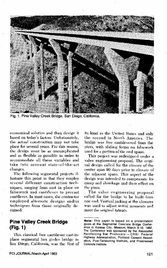
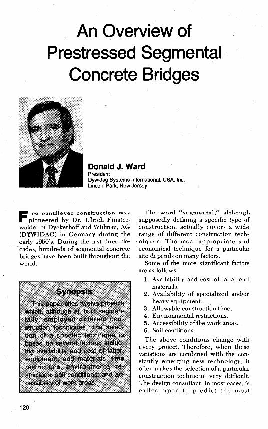
Fig. 1. Pine Valley Creek Bridge, San Diego, California.
economical solution and then design itbased on today's factors. Unfortunately,the actual construction may not takeplace for several years. For this reason,the design must be as uncomplicatedand as flexible as possible in order toaccommodate all these variables andtake into account state-of-the-artchanges.
The following segmental projects il-lustrate this point in that they employseveral different construction tech-niques, ranging from cast in place onfalsework and cantilever to precastcantilever. In most cases, the contractoremployed alternate designs and/ortechniques from those originally de-signed.
Pine Valley Creek Bridge(Fig. 1)
This classical free cantilever cast-in-place segmental box girder bridge inSan Diego, California, was the first of
its kind in the United States and onlythe second in North America. Thebridge was free cantilevered from thepiers, with sliding forms on falseworkused for a portion of the end spans.
This project was redesigned under avalue engineering proposal. The origi-nal design called for the closure of thecenter span 90 days prior to closure ofthe adjacent spans. This aspect of thedesign was intended to compensate forcreep and shrinkage and their effect onthe piers.
The value engineering proposalcalled for the bridge to be built fromone end. Vertical jacking at the closureswas used to adjust initial moments andmeet the original intents.
Note: This paper is based on a presentationgiven at the Segmental Concrete Bridge Confer-ence in Kansas City, Missouri, March 9-10, 1982.The Conference was sponsored by the AssociatedReinforcing Bar Producers — CRSI, FederalHighway Administration, Portland Cement Associ-ation, Post-Tensioning Institute, and PrestressedConcrete Institute.
PCI JOURNAUMarch-April 1983 121

Fig. 2. Eel River Bridge, California.
Eel River Bridge (Fig. 2)The Eel River Bridge in California
was originally designed as a cast-in-place continuous prestressed concretebox girder built on falsework. The con-tractor made a value engineering pro-posal to construct the bridge segmen-tally, using sliding forms. Only a por-tion of the bridge was falseworked, in-cluding bottom slab soffit, at any onetime.
The segments were then cast inlengths varying between 40 and 75 ft(12.2 and 22.9 m) with the use of slidingforms, and post-tensioned as the workprogressed. The total length of false-work required at any one time was ap-proximately 25 percent of the totallength of bridge. The formwork re-quired was approximately 3 percent ofthe total contact form surface.
The method selected provided econ-omy by allowing repetitive uses of thesame falsework and forming material. Italso allowed the first few spans to be
constructed and stressed before false-work was removed during the winterand spring high water seasons.
Kipapa Stream Bridge(Fig. 3)
The Kipapa Stream Bridge in Hono-lulu, Hawaii, was originally designedas a cast-in-place continuous pre-stressed concrete box girder built onfalsework. This $12 million bridge wasvalue engineered at considerable sav-ings and built by the free cantilevermethod.
The twin superstructures, providing aroadway approximately 120 ft (36.6 m)wide and 2000 ft (609.6 m) long, wereconstructed using a combination ofform travelers and .falsework. One in-teresting aspect of the design whichalso facilitated the construction was theabsence of transverse expansion jointsexcept at each abutment.
122
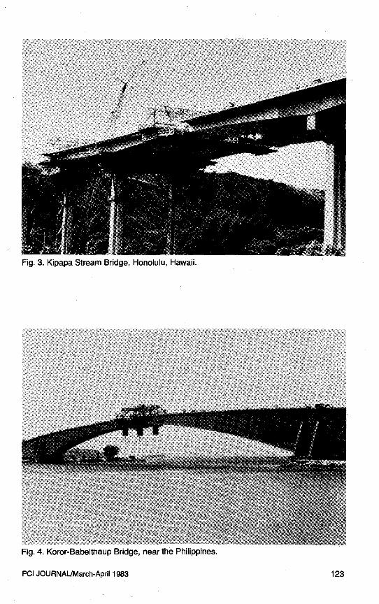
Fig. 3. Kipapa Stream Bridge, Honolulu, Hawaii.
Fig. 4. Koror-Babelthaup Bridge, near the Philippines.
PCI JOURNAUMarch-April 1983 123
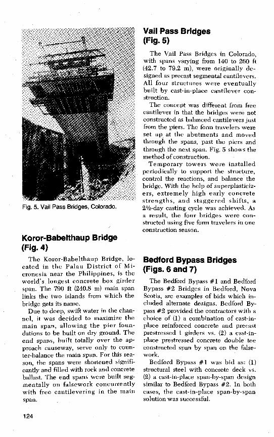
Fig. 5. Vail Pass Bridges, Colorado.
Koror-Babeithaup Bridge(Fig. 4)
The Koror-Babelthaup Bridge, lo-cated in the Palau District of Mi-cronesia near the Philippines, is theworld's longest concrete box girderspan. The 790 ft (240.8 m) main spanlinks the two islands from which thebridge gets its name.
Due to deep, swift water in the chan-nel, it was decided to maximize themain span, allowing the pier foun-dations to be built on dry ground. Theend spans, built totally over the ap-proach causeway, serve only to coun-ter-balance the main span. For this rea-son, the spans were shortened signifi-cantly and filled with rock and concreteballast. The end spans were built seg-mentally on falsework concurrentlywith free cantilevering in the mainspan.
Vail Pass Bridges.(Fig. 5)
The Vail Pass Bridges in Colorado,with spans varying from 140 to 260 ft(42.7 to 79.2 m), were originally de-signed as precast segmental cantilevers.All four structures were eventuallybuilt by cast-in-place cantilever con-struction.
The concept was different from freecantilever in that the bridges were notconstructed as balanced cantilevers justfrom the piers. The form travelers wereset up at the abutments and movedthrough the spans, past the piers andthrough the next span. Fig. 5 shows themethod of construction.
Temporary towers were installedperiodically to support the structure,control the reactions, and balance thebridge. With the help of superplasticiz-ers, extremely high early concretestrengths, and staggered shifts, a2½-day casting cycle was achieved. Asa result, the four bridges were con-structed using five form travelers in oneconstruction season.
Bedford Bypass Bridges(Figs. 6 and 7)
The Bedford Bypass #1 and BedfordBypass #2 Bridges in Bedford, NovaScotia, are examples of bids which in-cluded , alternate designs. Bedford By-pass #2 provided the contractors with achoice of (1) a combination of cast-in-place reinforced concrete and precastprestressed I girders vs. (2) a cast-in-place prestressed concrete double teeconstructed span by span on the false-work.
Bedford Bypass #1 was bid as: (1)structural steel with concrete deck vs.(2) a cast-in-place span-by-span designsimilar to Bedford Bypass #2. In bothcases, the cast-in-place span-by-spansolution was successful.
124

Fig. 6. Bedford Bypass Bridge No. 2, Bedford, Nova Scotia.
Fig. 7. Bedford Bypass Bridge No. 1, Bedford, Nova Scotia.
PCI JOURNAL/March-April 1983 125

Fig. 8. Grand Mere Bridge, St. Maurice, Quebec.
Fig. 9. Shubenacadie River Bridge, Nova Scotia.
Grand Mere Bridge (Fig. 8) T h e G r a n d M e r e B r i d g e i n S t .
Maurice, Quebec, with a 595 ft (181.4 m) main span, was a similar but smaller version of the Koror-Babelthaup Bridge. The shortened ballasted e n d spans were also built on falsework. However, in this particular case they were con- structed prior to and not concurrently with the main span.
Shu benacadie River Bridge (Fig. 9)
The Shubenacadie River Bridge in Nova Scotia has a 700 ft (213.4 m) main span flanked by 375 ft (114.3 m) side spans. Single temporary falsework bents were used in the side spans. The bents reduced the unbalanced dead load moment and allowed the total side span to be built with form travelers.
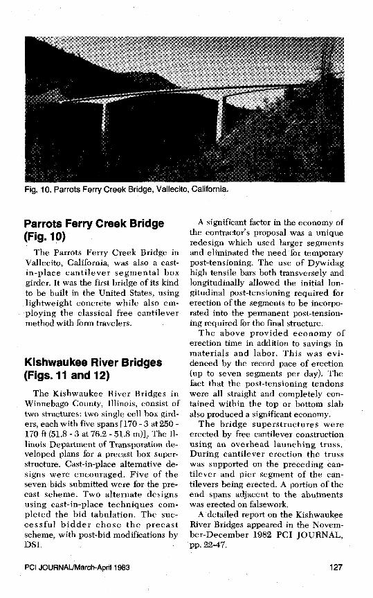
Fig. 10. Parrots Ferry Creek Bridge, Vallecito, California.
Parrots Ferry Creek Bridge(Fig. 10)
The Parrots Ferry Creek Bridge inVallecito, California, was also a cast-in-place cantilever segmental boxgirder. It was the first bridge of its kindto be built in the United States, usinglightweight concrete while also em-ploying the classical free cantilevermethod with form travelers.
Kishwaukee River Bridges(Figs. 11 and 12)
The Kishwaukee River Bridges inWinnebago County, Illinois, consist oftwo structures: two single cell box gird-ers, each with five spans [170-3 at 250 -170 ft (51.8 - 3 at 76.2 - 51.8 m)] ; The Il-linois Department of Transporation de-veloped plans for a precast box super-structure. Cast-in-place alternative de-signs were encouraged. Five of theseven bids submitted were for the pre-cast scheme. Two alternate designsusing cast-in-place techniques com-pleted the bid tabulation. The suc-cessful bidder chose the precastscheme, with post-bid modifications byDSI.
A significant factor in the economy ofthe contractor's proposal was a uniqueredesign which used larger segmentsand eliminated the need for temporarypost-tensioning. The use of Dywidaghigh tensile bars both transversely andlongitudinally allowed the initial lon-gitudinal post-tensioning required forerection of the segments to be incorpo-rated into the permanent post-tension-ing required for the final structure.
The above provided economy oferection time in addition to savings inmaterials and labor. This was evi-denced by the record pace of erection(up to seven segments per day). Thefact that the post-tensioning tendonswere all straight and completely con-tained within the top or bottom slabalso produced a significant economy.
The bridge superstructures wereerected by free cantilever constructionusing an overhead launching truss.During cantilever erection the trusswas supported on the preceding can-tilever and pier segment of the can-tilevers being erected. A portion of theend spans adjacent to the abutmentswas erected on falsework.
A detailed report on the KishwaukeeRiver Bridges appeared in the Novem-ber-December 1982 PCI JOURNAL,pp. 22-47.
PCI JOURNAL/March-April 1983 127
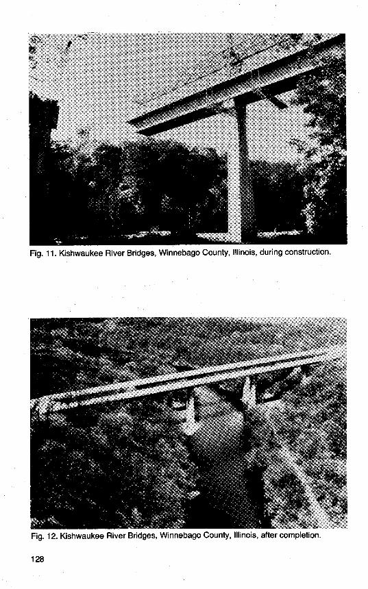
Fig. 11. Kishwaukee River Bridges, Winnebago County, Illinois, during construction.
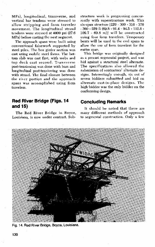
Fig. 12. Kishwaukee River Bridges, Winnebago County, Illinois, after completion.
128

Fig. 13. Genessee River Bridge, Rochester, New York.
Genessee River Bridge (Fig. 13)
T h e G e n e s s e e R i v e r B r i d g e i n Rochester, New York, is a good exam- ple of the combination of two segrnen- tal construction techniques. The twin structures consist of two two-cell con- crete box girders and have a combined width of 120 ft (36.6 m) and a total length of approximately 2050 ft (624.8
T h e river span and two adjacent spans [270 - 430 - 270 ft (82.3 - 131.1 - 82.3 m)l were built as free cantilevers . - using form travelers. T h e approach spans [seven spans varying from 140 to 180 ft (42.7 to 74.9 m)] were con- structed segmentally - span by span on falsework.
For the cantilever vortion of the bridge, four form travelers were used, two for each structure. Segments of 16 ft 3 in. (4.95 m) were cast in alternating sequence about the centerline of the
pier. The unbalanced moment about the pier was taken by a temporary con- crete pier supported on piling and tied down with post-tensioned anchors. The temporary bearings and bents were re- moved after the spans were closed.
Cantilever work progressed at a rate of approximately one segment per form traveler per week [65 ft (19.8 m) of two-cell box girder per week].
This pace is noteworthy because con- siderable time was needed for the con- crete to reach the required stressing strength. Ordinarily, the use of addi- tives and/or high early strength con- crete permits stressing the second day of the cycle (first day after concrete placement). In this case, the concrete did not reach initial stressing strength of 2500 psi (17.2 MPa) until the third day and sometimes the fourth day.
The use of high early strength ce- ment could have reduced the cycle time by approximately 2 days. When the concrete reached 2500 psi (17.2
MPa), longitudinal, transverse, andvertical bar tendons were stressed toallow stripping and form travelermovement. The longitudinal strandtendons were stressed at 4000 psi (27.6MPa) before casting the next segment.
The approach spans were built usingconventional falsework supported bysteel piles. The box girder section wascast using mobile steel forms. The bot-tom slab was cast first, with webs andtop deck cast second. Transversepost-tensioning was done with bars andlongitudinal post-tensioning was donewith strand. The final closure betweenthe river portion and the approachspans was accomplished using formtravelers.
Red River Bridge (Figs. 14and 15)
The Red River Bridge in Boyce,Louisiana, is now under contract. Sub-
structure work is progressing concur-rently with superstructure work. Thissix-span structure [229 - 300 - 310 - 370- 360 - 229 ft (69.8 - 91.4 - 94.5 - 112.8 -109.7 - 69.8 m)] will be constructedusing four form travelers. Temporarybents will be used in the end spans toallow the use of form travelers for theentire span.
This bridge was originally designedas a precast segmental project, and wasbid against a structural steel alternate.The specifications also allowed thesubmission of contractors' alternate de-signs. Interestingly enough, six out ofseven bidders submitted and bid onalternate cast-in-place designs. Thehigh bidder was the only bidder on theconforming design,
Concluding RemarksIt should be noted that there are
many different methods of approachto segmental construction. Only a few
Fig. 14. Red River Bridge, Boyce, Louisiana.
130
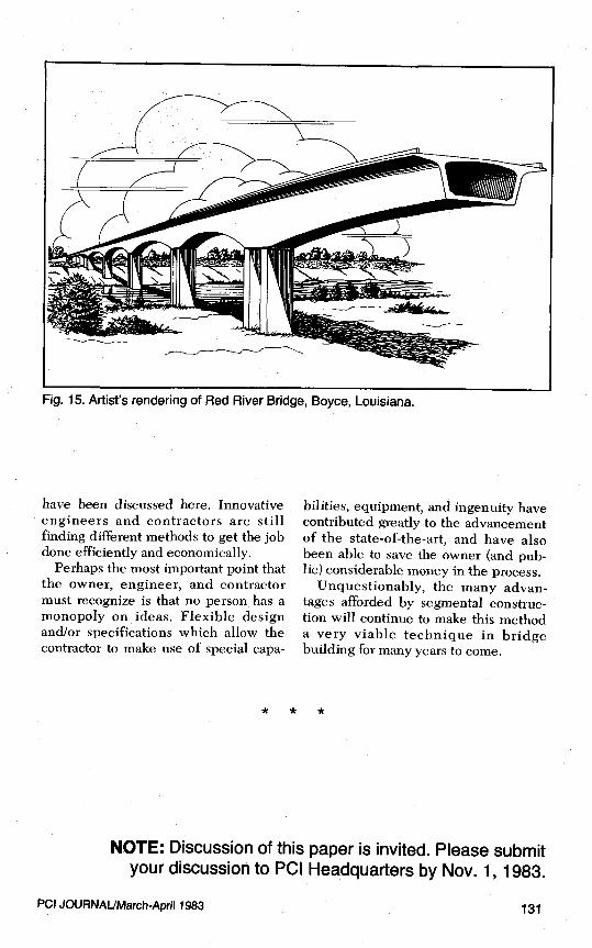
Fig. 15. Artist's rendering of Red River Bridge, Boyce, Louisiana.
have been discussed here. Innovativeengineers and contractors are stillfinding different methods to get the jobdone efficiently and economically.
Perhaps the most important point thatthe owner, engineer, and contractormust recognize is that no person has amonopoly on ideas. Flexible designand/or specifications which allow thecontractor to make use of special capa-
bilities, equipment, and ingenuity havecontributed greatly to the advancementof the state-of-the-art, and have alsobeen able to save the owner (and pub-lic) considerable money in the process.
Unquestionably, the many advan-tages afforded by segmental construc-tion will continue to make this methoda very viable technique in bridgebuilding for many years to come.
NOTE: Discussion of this paper is invited. Please submityour discussion to PCI Headquarters by Nov. 1, 1983.
PCI JOURNAL/March-ApriJ 1983 131