standards/manuals/ guide lines for small hydro … · generator transformers and hydro mechanical...
TRANSCRIPT
STANDARDS/MANUALS/ GUIDE LINES FOR SMALL HYDRO DEVELOPMENT
3.11 Electro-Mechanical– Operation and Maintenance
Sponsor: Ministry of New and Renewable Energy Govt. of India
Lead Organization: Alternate Hydro Energy Center Indian Institute of Technology Roorkee
December 2012

Contact: Dr Arun Kumar Alternate Hydro Energy Centre, Indian Institute of Technology Roorkee, Roorkee - 247 667, Uttarakhand, India Phone : Off.(+91 1332) 285821, 285167 Fax : (+91 1332) 273517, 273560 E-mail : [email protected], [email protected]
DISCLAIMER The data, information, drawings, charts used in this standard/manual/guideline has been drawn and also obtained from different sources. Every care has been taken to ensure that the data is correct, consistent and complete as far as possible. The constraints of time and resources available to this nature of assignment, however do not preclude the possibility of errors, omissions etc. in the data and consequently in the report preparation. Use of the contents of this standard/manual/guideline is voluntarily and can be used freely with the request that a reference may be made as follows: AHEC-IITR, “3.11 Electro-Mechanical – Operation and Maintenance”, standard/manual/ guideline with support from Ministry of New and Renewable Energy, Roorkee, December. 2012.

PREAMBLE
There are series of standards, guidelines and manuals on electrical, electromechanical
aspects of moving machines and hydro power from Bureau of Indian Standards (BIS), Rural Electrification Corporation Ltd (REC), Central Electricity Authority (CEA), Central Board of Irrigation & Power (CBIP), International Electromechanical Commission (IEC), International Electrical and Electronics Engineers (IEEE), American Society of Mechanical Engineers (ASME) and others. Most of these have been developed keeping in view the large water resources/ hydropower projects. Use of the standards/guidelines/manuals is voluntary at the moment. Small scale hydropower projects are to be developed in a cost effective manner with quality and reliability. Therefore a need to develop and make available the standards and guidelines specifically developed for small scale projects was felt.
Alternate Hydro Energy Centre, Indian Institute of Technology, Roorkee initiated an exercise of developing series of standards/guidelines/manuals specifically for small scale hydropower projects with the sponsorship of Ministry of New and Renewable Energy, Government of India in 2006. The available relevant standards / guidelines / manuals were revisited to adapt suitably for small scale hydro projects. These have been prepared by the experts in respective fields. Wide consultations were held with all stake holders covering government agencies, government and private developers, equipment manufacturers, consultants, financial institutions, regulators and others through web, mail and meetings. After taking into consideration the comments received and discussions held with the lead experts, the series of standards/guidelines/manuals are prepared and presented in this publication.
The experts have drawn some text and figures from existing standards, manuals,
publications and reports. Attempts have been made to give suitable reference and credit. However, the possibility of some omission due to oversight cannot be ruled out. These can be incorporated in our subsequent editions.
This series of standards / manuals / guidelines are the first edition. We request users to
send their views / comments on the contents and utilization to enable us to review for further upgradation.

Standards/ Manuals/Guidelines series for Small Hydropower Development General 1.1 Small hydropower definitions and glossary of terms, list and scope of different
Indian and international standards/guidelines/manuals 1.2 Part I
Planning of the projects on existing dams, Barrages, Weirs
1.2 Part II
Planning of the Projects on Canal falls and Lock Structures.
1.2 Part III
Planning of the Run-of-River Projects
1.3 Project hydrology and installed capacity 1.4 Reports preparation: reconnaissance, pre-feasibility, feasibility, detailed project
report, as built report 1.5 Project cost estimation 1.6 Economic & Financial Analysis and Tariff Determination 1.7 Model Contract for Execution and Supplies of Civil and E&M Works 1.8 Project Management of Small Hydroelectric Projects 1.9 Environment Impact Assessment 1.10 Performance evaluation of Small Hydro Power plants 1.11 Renovation, modernization and uprating 1.12 Site Investigations Civil works
2.1 Layouts of SHP projects
2.2 Hydraulic design 2.3 Structural design 2.4 Maintenance of civil works (including hydro-mechanical) 2.5 Technical specifications for Hydro Mechanical Works Electro Mechanical works 3.1 Selection of Turbine and Governing System 3.2 Selection of Generators and Excitation Systems 3.3 Design of Switchyard and Selection of Equipment, Main SLD and Layout 3.4 Monitoring, control, protection and automation 3.5 Design of Auxiliary Systems and Selection of Equipments 3.6 Technical Specifications for Procurement of Generating Equipment 3.7 Technical Specifications for Procurement of Auxiliaries 3.8 Technical Specifications for Procurement and Installation of Switchyard
Equipment 3.9 Technical Specifications for monitoring, control and protection 3.10 Power Evacuation and Inter connection with Grid 3.11 Operation and maintenance 3.12 Erection Testing and Commissioning

PERSON INVOLVED
1. Dr Arun Kumar, CSO & Principal Investigator ,AHEC,IIT, Roorkee 2. Dr S K Singal, SSO & Investigator,AHEC,IIT, Roorkee
Drafting Group
1. Mr. S K Tyagi, Consultant, AHEC, IIT, Roorkee Consultation Group
1. Dr Arun Kumar,AHEC,IIT, Roorkee 2. Mr S.N.Singh, AHEC,IIT, Roorkee 3. Dr S K Singal,AHEC,IIT, Roorkee 4. Prof. O.D.Thapar, Consultant, AHEC,IIT, Roorkee 5. Mr. S.C.Jain, Consultant, AHEC,IIT, Roorkee 6. Mr. Masum Ali, Consultant, AHEC,IIT, Roorkee 7. Mr. A.K.Chopra, Consultant, SHP, MNRE,GOI, New Delhi 8. Mr. P.C.Kureel, CEA, New Delhi 9. Mr. R.P.Goel, Consultant, Hardwar 10. Mr. Jugal Kishore, Consultant, Hardwar 11. Mr. S.V.Dinkar, Consultant, Pune 12. Mr. Surendra Singh ,PGCL, PEDA,Chandigarh 13. Mr. Pankaj Kulshreshtha, UJVNL, Dehradun 14. Mr. Himanshu Tiwari, UJVNL, Dehradun 15. Mr. A.K.Singh, UJVNL, Dehradun 16. Mr. P.K.Singhal, UPJVNL, Lucknow 17. Mr. V.K.Sharma, THDC, Rishikesh 18. Mr. U Ukhal, HPPCL, Himachal Pradesh 19. Mr..S.S.Sidhu, HPP India Pvt. Ltd, Noida 20. Mr. K.C.Arora, Pentaflo Hydro power Ltd 21. Mr. P.K.malohtra, Pentaflo Hydro power Ltd 22. Mr. Sanjeev Handu, Andriz Hydro power Ltd. 23. Mr. Vishnupad Saha, Andriz Hydro power Ltd. 24. Mr. Dinesh Rajput, Andriz Hydro power Ltd. 25. Mr. Pradeep Dube, Tanushree Hydropower Consultants, Noida 26. Mr. H.M.Sharma, Jyoti Ltd.,Vadodra 27. Mr. Viral B Mahida, Jyoti Ltd.,Vadodra 28. Mr. Nishant Saha, Jyoti Ltd.,Vadodra

CONTENTS
ITEMS PAGE NO Guidelines for Operation and Maintenance of Small Hydro Power Station 1.0 General 1 1.1 Scope 1 1.2 References 1 2.0 Guidelines For Operation 1 2.1 Introduction 1 2.2 Operation of Power Plant 3 3.0 Guidelines for Maintenance 15 3.1 Introduction 15 3.2 Type of Maintenance 16 3.3 Requirement of Effective Maintenance 17 3.4 Maintenance of Small Hydropower Stations 17 4.0 General Guidelines 74 4.1 Taking Over of Plant for O&M 74 4.2 Manpower, Selection and Training 75 4.3 Essential T&P, Instruments Etc. 76 4.4 Fire Protection and Fire Fighting 76 4.5 Safety Aspect of Running SHP 77 4.6 Documentation 80
LIST OF FIGURES
FIGURE NO. TITLE PAGE NO. 1 Eroded Buckets of Pelton Runner 24 2 Eroded Niddle 24 3 Eroded Kaplan Runner Blade 25 4 Eroded Francis Runner 25 5 Runner Cavitation 26 6 Eroded Guidevanes 26 7 Checking Labyrinth Concentration 58 8 Balancing of Runner 59 9 Checking concentricity of runner blades 60 10 Arrangement for Hydraulic Testing of Kaplan Runner in
Service Bay 61
11 Position of Dial Indicators 63 12 Resultant Method of Throw Calculation 65 13 Calculation of Shims between Flanges 66 14 Example of Scrapping on textolite surface of mirror disc to
be fixed with the thrust collar 66
15 Checking Verticality of Generator Shaft 67

FIGURE NO. TITLE PAGE NO. 16 Arrangement for Load Sharing 68 17 Checking Balancing of Generator 69 18 Showing Misalignment of Turbine Shaft and Generator
Shaft of Horizontal Unit 71
19 Horizontal Shaft Generator Bearing Arrangement 72 20 Displacements of Generator Bearings 73
LIST OF TABLES
TABLE NO. TITLE PAGE NO.
1 Periodical Maintenance of Hydro Generator 31 2 Daily Checks 40 3 Annual Inspection & Maintenance 40 4 Periodical inspection and maintenance of transformers 47 5 Degree of polymerization and Furan contents 53 6 Allowable Deviation in Shaft Coupling 62 7 Resultant Method of Alignment 64 8 Table for Recording Measurements 72 9 Permissible Deviations in Alignment of Horizontal Hydro
Generating Unit 73
10 Format for Daily Log Sheet 82 11 Format for Daily Generation, Export/Import of Energy 83 12 Format for Daily Tripping 83 13 Format for Daily Outage Report 84 14 Format for Daily Water Availability/ Spillage Report 84 15 Format for Monthly Unit Availability Report 85 16 Format for Monthly Generation Report 85 17 Format for Monthly Tripping Report 86 18 Format for Monthly Outage Report 87 19 Format for Monthly Deemed Generation Report 88

AHEC-IITR/MNRE/SHP Standards/ E&M Works- Operation and Maintenance 1
GUIDELINES FOR OPERATION AND MAINTENANCE OF SMALL HYDRO POWER STATION
1.0 GENERAL
1.1 Scope
This guide covers operation and maintenance aspect of hydro turbine, generator,
generator transformers and hydro mechanical equipment of a small hydro power plant. This also covers general brief guidelines on disaster management and safety aspects.
1.2 References R1 IEEE 1248-1998 IEEE Guide for commissioning of Electrical systems in
Hydro- electrical Power Plants R2 IEEE 492-1999 IEEE Guide for operation and maintenance of hydro
generators R3 IEC 605456-1976 Guide for commissioning, operation and maintenance of
Hydraulic Turbines R4 Gonchrov A-1995 Hydro Power Station – Generating Equipment and its
Installation -N,Energia Mascova-1972(translated from Russian under Israel programme for scientific translation, Jruslum
R5 INHA -2005 Hand Book on Operation and Maintenance of Hydropower Stations
R6 FIST,USBR Vol.2-1-2001
Alignment of vertical shaft hydro units
R7 FIST,USBR Vol.2-5-1987
Turbine repair
R8 FIST,USBR Vol.2-7-1994
Mechanical overhaul procedures
R9 FIST,USBR Vol.4-1A. -2009
Maintenance scheduling of mechanical equipment
R10 FIST,USBR Vol.4-.1B -2012
Maintenance scheduling of electrical equipment
ABBREVIATIONS
IEC : International Electro-technical Commission IEEE : Institute of Electrical & Electronic Engineers
INHA : Indian National Hydropower Association FIST : Facilities Instructions, Standards And Techniques, Bureau of Reclamation of, USA http://www.usbr.gov/power/data/fist_pub.html
2.0 GUIDE LINES FOR OPERATION 2.1 Introduction
Operation of hydropower plant involves understanding of operation of hydraulic features and equipments. All features may not be included in every plant and depend on type

AHEC-IITR/MNRE/SHP Standards/ E&M Works- Operation and Maintenance 2
of plant, water source, turbine & generator installed and power evacuation arrangement. The operation of hydropower plant generally consists of following
2.1.1 Civil & Hydraulic Structures
2.1.1.1 Civil
(a) Lake/pond/river/canal as main water source (b) Dam/Diversion weir/Diversion barrage (c) Head regulator (d) Power channel/tunnel/pipe (e) Desilting arrangement (f) Forebay (g) Bye pass/Spillway (h) Siphon intake (i) Surge Tank/Spilling pipe/ spilling channel (j) Tail Race
2.1.1.2 Hydro-mechanical systems
(a) Barrage/Dam gates and hoisting system (b) Head regulator gates and hosting system (c Intake gates and hoisting system (d) Trash racks and trash cleaning system (e) Bye pass gates and hoisting system (f) Penstocks and associated valves (g) Draft tube gates and hoisting system
2.1.2 Power House 2.1.2.1 Mechanical
(a) Main inlet valve (Butterfly/Spherical valve) (b) Bye pass valve (c) Inlet bend and branching pipes (d) Drain valve (e) Pressure reducing valve for cooling water system (f) Cooling water system (g) Turbine and its auxiliaries (h) Draft tube (i) Governor, associated OPU and guide apparatus (j) Station auxiliaries such as:-
(i) EOT cranes/hoists (ii) Station compressor (iii) Drainage & Dewatering system (iv) Diesel Generating. Set
2.1.2.2 Electrical
(a) Hydro generator and auxiliaries

AHEC-IITR/MNRE/SHP Standards/ E&M Works- Operation and Maintenance 3
(b) AVR & Excitation system (c) Generator protection/relay and control panel (d) A.C. auxiliary supply (e) D.C. control supply, batteries & battery charger (f) TG start up panel (g) Synchronizing panel (h) Generator transformer (i) Station transformer (j) Unit auxiliary transformer (if applicable) (k) Relay and control panel for transformers and feeders
2.1.3 Switchyard
(a) Switchyard structure (b) Bus bar system (c) VCBs/SF6 circuit breakers (d) Isolators (e) CTs (f) PTs (g) LA (h) Line side Isolator (i) Surge counters (j) Outgoing lines
2.1.4 Other Systems
(a) Lighting system, emergency lighting (b) Station earthing, lightening protection (c) Communication system (d) Fire fighting and hydrant system (e) Safety tagging & safety interlocks
2.2 Operation of Power Plant (i) The staff responsible for the operation should be well conversant with technical
details and importance of following:-
(a) Intake gates ,bye pass gates, draft tube gates & fore bay (b) Inlet valves (c) Turbine (d) Generator (e) Generator Transformer (f) Switchyard (g) Synchronizing with grid (h) Shut down of machine (i) Emergency shutdown of machine (j) Importance of log sheets (k) Shut down procedure and clearance (l) Water restriction, if any (m) Permission from ALDC(Area Load Dispatch Centre)

AHEC-IITR/MNRE/SHP Standards/ E&M Works- Operation and Maintenance 4
(n) Proper working of i. Communication system
ii. AC Power iii. DC Power iv. Fire fighting system v. Cooling water system
vi. Drainage & dewatering system vii. H.S. lubrication system(where ever provided)
viii. L.P. & H.P. compressed air system (where ever provided) ix. Protection system
(ii) Guidelines for operation of power plant shall have two elements:-
(a) Water operation (b) Operation of Power Plant
2.2.1 Water Operation
Just like operation of Turbine Generator set or a transformer, efficient water operation forms an important part of hydro power plant be it large storage plant or small run of river plant. Water operation means operation of following systems of the hydro plant in such a manner that efficiency of plant is maximum. It is generally reflected in kWH / Cumec. 2.2.1.1 Catchment area
The area gives the runoff into the lake/pond/river during rainy season. Run off rate cubic m/mm should be known to operator to adjust generation accordingly. 2.2.1.2 Lake/Storage/Pond
The operation of lake based plant means keeping the level such that during rainy season the over flow chances are minimum. In case of diversion type plants, it is essential to keep the gates open during flood conditions to avoid flooding and lower them only when rain is low or over. In such plants, it is essential to check that there is no leakage from the gates or stop log gates. If operator notice that the leakage is more, he should pass on his observation to higher authorities to ensure corrective measures in the interest of having more generation. 2.2.1.3 Run of river plants
Availability of water is more important factor in operation of hydro power plants. It is therefore, essential to generate continuously to its full capacity during monsoon season. Failure of a machine during monsoon can cause a substantial generation loss. All operation staff must, therefore, be very vigilant during this period. In lean season diversion barrage gates/diversion weir gates are checked for leakage, corrective measures are taken as soon as possible so that there may not be any generation loss on this account. 2.2.1.4 Power channel/duct/canal/pipe
The operation of open channel/duct is critical to water operation and efficiency of plant. Depending upon the length, condition of lining, head on head regulator, time required
AHEC-IITR/MNRE/SHP Standards/ E&M Works- Operation and Maintenance 5
discharge to reach fore bay and to the machine. The time taken by water to reach the turbine will depend on many factors and only experience will make the operator perfect. 2.2.1.5 Forebay
Forebay is a essential part of any water conductor system with open channel. It serves the purpose of connecting penstocks with gates and acts as tank. It takes care of small variation in generation and acts as desilting basin in some cases. The operation of fore bay is important during picking up load and at the time of tripping of machines. Actual over flow, through bye pass, is always recorded to calculate water wasted during over flow, especially during lean season. 2.2.2 Operation of Power Station
The operation of power station requires that its staff is trained and well versed with all necessary technical as well as basic trouble shooting knowledge. As a brief description to bring out some details of operating a SHP, the following checks are to be made before starting of machine:- 2.2.2.1 Check List for starting of machine (After long shut down) 2.2.2.1.1 Mechanical 2.2.2.1.1.1 Intake, bye pass, stop log and DT gates
(a) Check bye pass gates are not mechanically locked and all valves are in okay position.
(b) Check position of intake gate and Draft Tube Gate. (c) Check position of stop log gates*. (d) Check filling line valve of penstock. (e) Check electric supply to gates is O.K. (f) Check position of draft tube gate (should be lifted)*
2.2.2.1.1.2 Power station (i) Inlet valve:-
(a) AC power for pump operation (b) HP compressed air (c) Locking pin position (d) Oil level and pressure in OPU
(ii) Others:-
(a) Check valves: i. Check spiral drain valve is closed
ii. Check Draft Tube drain valve is closed iii. Position of strainer valves ensure water flowing in cooling pipes iv. Gland seal clean water valve open v. Air seal valve closed
vi. Top cover drain system okay
AHEC-IITR/MNRE/SHP Standards/ E&M Works- Operation and Maintenance 6
(b) Check oil levels: i. Pressure accumulator and oil sump of OPU system
ii. Turbine Guide bearing iii. Lower Guide bearing iv. Upper Guide bearing v. Thrust bearing
(c) Check pressures: i. Penstock pressure
ii. Spiral casing after opening of MIV iii. OPU iv. Stator cooling water pressure and flow of water through flow meter v. Thrust bearing (if HP lub system is provided)
vi. Cooling water pressure vii. Sealing water pressure
viii. Air pressure for brakes (d) Check working of systems
i. Top cover drain ii. Oil leakage unit
iii. Oil cooling unit iv. Oil pressure unit v. Brakes for horizontal units and brake & jack system for vertical set up
vi. Position of CO2 batteries(if provided) vii. Guide vane lock (on or off)
viii. Check jacking/de-jacking of m/c ix. Check flow relays x. Check emergency slide valve reset
2.2.2.1.2Electrical 2.2.2.1.2.1 Check list general
i. D.C. System ii. Grid Power
iii. Diesel Generating Set power iv. Event logger v. Disturbance logger
2.2.2.1.2.2 Check list of generator
i. Brake system ii. Cooling water for bearings
iii. Generator fire fighting, if applicable iv. AVR condition* v. DC supply for field flashing
vi. IR values*/PI vii. Jack position*
viii. H.P. lubrication system ix. Check earth link for bus duct*

AHEC-IITR/MNRE/SHP Standards/ E&M Works- Operation and Maintenance 7
2.2.2.1.2.3 Check list for transformers
i. Cooling water system ii. Fire-fighting system
iii. Transformer cooling oil pump position iv. Buccholz relay v. Oil level in conservator
vi. Colour of silica gel vii. IR of winding and core*
viii. BDV of oil* 2.2.2.1.2.4 Check list for switchyard
i. Compressed air in case ABCBs are used ii. SF6 gas pressure in case of SF6 breaker
iii. Earthing switch position iv. Isolator position – close v. Breaker position – off
vi. Line isolator position
2.2.2.2 Operations
(i) Intake Gate Opening (a) Check intake gate supply (b) Check hoisting system (c) Give raising command (d) Check gate position in raised condition
(ii) Inlet Valve Opening
(a) Put oil pumps on ‘auto’ mode (b) Open bye pass valve manually or (c) Give opening command to bypass auto valve (d) Check water pressure on spiral side (e) Give opening command to inlet valve on equalized pressure (f) Check closing of valve in auto and on emergency command* (g) Check opening of inlet valve in auto operation*
(iii) Turbine Operation
(a) Put oil pumps on auto mode to maintain required pressure in pressure accumulator
(b) Check availability of Nitrogen cylinder and check pressure of the same (c) Check air pressure for maintaining proper oil level in pressure accumulator
(if provided) (d) Open cooling water for bearings (e) Open shaft seal water (f) Put brake on auto mode (g) Unlock guide vane lock (h) Put machine on auto mode
AHEC-IITR/MNRE/SHP Standards/ E&M Works- Operation and Maintenance 8
(iv) Generator Operation (a) Select AVR Auto/Manual mode as required (b) Keep fire fighting system operative(where provided) (c) Switch on D.C. supply for excitation flashing (d) At 30% of generator voltage D.C. supply from battery cuts off (e) At 90% speed switch on generator excitation, if not on auto (f) Start machine on Auto or Manual mode as required. (g) Check for abnormal sound & vibration. (h) Check stabilization of bearing temperatures.
(v) Synchronization
(a) Synchronization i. Check grid voltage & frequency.
ii. Check generator voltage & frequency. iii. Reduce or increase generator voltage & frequency to match with
line voltage & frequency. iv. Put synchroscope in ON position needle will start moving and
lamps will start glowing. Needle on12 O’clock position and lamps in dark position indicate that voltages and frequencies of grid and generator respectively are matching.
v. At equal grid & generator voltage and frequency, close generator breaker at approaching 12 O’clock position.
vi. Now generator is synchronized with grid. vii. Take minimum prescribed load immediately.
(b) Checks after synchronizing and taking load
i. Unit control board supply is changed to Unit Aux. Transformers. ii. Change excitation from Manual to Auto mode.
iii. Transformer “Motor for oil pump, if OFW cooling water system is provided” started.
iv. All parameters in control room are matching and correct. v. General check up of machine and other unit auxiliaries at all floors.
NOTE: For short shut down certain checks with marked with * are not required 2.2.2.3 Checks at the Time of Shift Change Over (Machine Running on Load) (i) General:
(a) Check Lighting, ventilation and air conditioning. (b) Check Water levels in Fore bay & Tail Race Channel. (c) Check Availability of discharge. (d) Check Communication Systems. (e) Check Instructions and status of various equipment and work permit/ shut
downs/ break downs/ shut down. (f) Check General cleanliness of the area, equipment and control panels etc. (g) Check all indication lamps are glowing. (h) Check with test push button that all fault indication lamps are OK. (i) Physical check of all sub distribution boards installed in P.S. (j) Check all inlet exhaust fans are working. (k) Check all batteries are physically in good condition.

AHEC-IITR/MNRE/SHP Standards/ E&M Works- Operation and Maintenance 9
(l) Check battery and battery chargers are in normal working conditions (visual inspection).
(ii) Turbine, generator and Governor: (a) Check Temperature of following:
-Thrust bearing -Upper guide bearing -Lower guide bearing
(b) Check following in normal working condition: -Cooling water flow and pressure of all bearings at inlet & outlet -Sealing water flow and pressure -Top cover drainage system (only for vertical units) -Stator cooling water flow and pressure, if stator air coolers are provided
(c) Check oil level in housings of all bearings. (d) Check if, there is vibration or abnormal sound in OPU pumps. (e) Check grease in the container of centralized grease lubrication system. (f) Check working of following:
-OPU pump 1 and 2 -OLU pump -Drainage pump & dewatering pumps -Governor compressor -General purpose compressor -Cooling water strainers
(g) Check running and vibration of machine and ensure nothing is abnormal by feeling.
(h) Check water, and oil flow indicators. (i) Check physical appearance of various systems such as man holes, valves,
indicators etc. (j) Check G.V. Servomotor stroke and R.B. angle is normal.
(iii) Generator, AVR & Excitation System:
(a) Watch running and vibration of machine and ensure nothing is abnormal by feeling.
(b) Check for any sparking between the brushes & slip rings, applicable for Static Excitation only.
(c) Check temperatures of stator winding & core. Ensure that these are within limit.
(d) Check that all instruments and indicators mounted on unit control board, governor panel and AVR and excitation panel are in OK condition.
(e) Check for any abnormality, sound, chattering in bus duct, generator barrel, neutral cubicle
(iv) Control room:
(a) Check that all parameters indicated on various panel are matching. (b) Check all indicating lamps are glowing. Also check annunciations are OK. (c) Check movement of all pointers of analogue meters and reset them. (d) Check all instruments mounted on panels are in working order. (e) Check all facias & relays are reset.
AHEC-IITR/MNRE/SHP Standards/ E&M Works- Operation and Maintenance 10
(f) Check rear of all panels and mounting on this side for OK condition. (g) Check emergency lighting system is OK. (h) Check position of circuit breakers for outgoing lines. (i) Check grid voltage & frequency.
(v) L.T. room:
(a) Check all indication lamps are glowing. (b) Have general look on instruments and relays mounted on board. (c) Check various switches are in correct position. (d) Check whether supply to various distribution boards are OK.
(vi) DC Distribution Board, Battery Charger & Battery sets:
(a) Check D.C. voltage is correct. (b) Check batteries are in healthy condition. (c) Check D.C. supply is healthy by making momentarily float off. This would
ensure that batteries are connected with load. (d) Check both batteries are on float. (e) Check all the switches on DC board are in correct position. (f) Check that both chargers are functioning correctly. (g) Check all cells of battery bank are healthy. Their sp. gravity and cell voltage is
correct (in morning shift only).
(vii) Main Transformer: (a) See that oil level in conservator is OK & there is no leakage from anywhere. (b) Check that oil pressure and water pressure are normal. (c) Check that oil temperature and winding temperature are normal. (d) Check silica gel colour is normal. (e) See that oil and water flow indicators are normal. (f) Carry out following checks for healthy condition of Mulsifyre System
(wherever applicable): -Compressor -Power supply
(viii) Switchyard:
(a) Have general look at switchyard including bus bars, jumpers etc. Ensure that there is no sparking anywhere and everything is in order.
(b) Check compressed air system in case of ABCB is OK, if provided. (c) Check SF6 gas pressure in case of SF6 breaker. (d) Check position of all breakers, isolators & line isolator and cast a look on all
CTs, PTs, LAs, Surge counters, wave traps and coupling capacitor and ensure that everything is in order.
(ix) Routine maintenance to be carried out during each shift:
(a) Cleaning of all panels, instruments and equipment installed in power station. (b) Oiling and greasing of all equipment as per instructions. (c) Topping up of oil of proper grade in bearings and OPU sump. (d) Replacement of defective lamps, fuses etc. (e) Cleaning of trash racks. (f) Inspections of fore bay, bye pass gates, intake gates. (g) Draft tube gates and other appurtenant works. (h) Any other work as assigned.

AHEC-IITR/MNRE/SHP Standards/ E&M Works- Operation and Maintenance 11
Inspections and observations carried out during each shift shall be logged in daily in control room log book.
2.2.3 Preparing of Operation Manual
Every plant shall have an operation manual for guidance of operating staff. Generally it should include following subjects:
(i). General information about the Project
(ii). Salient features of the Project (iii). Equipment data (iv). Plant operation procedure
(a) Prestart checks (b) Starting procedure
-Auto -Manual
(c) Synchronizing and taking load (d) Normal shut down (e) Emergency shut down (f) Dead bus synchronizing (g) Taking D.G. set in service
(v). Problems during plant operation (vi). Planned plant outage procedure
(a) Water conductor system outage (b) Taking main transformer out for maintenance (c) Taking turbine generator set out of service (d) Plant outage for maintenance of machine (e) Outage request Form (f) Plant outage instructions (g) Procedure for operation personnel for giving planned plant outage.
(vii) Essential Drawings (Enclosure)
(a) Plant layout (b) Hydraulic layout (c) Main single diagram (d) Single line diagrams for LT supply, DC system, Greasing system and (e) CO2 system (where ever provided) (f) Plan of different floors (g) Transverse section through unit (h) Longitudinal section through centre line of unit (i) List of panels (j) Schematic diagrams of hydro mechanical system
(viii) Operation of Auxiliaries and other system installed in P.S.
(a) Turbine Governor Oil Pressure Unit (b) Cooling water system (c) Drainage and Dewatering system (d) AVR & excitation system (e) Generator neutral grounding system

AHEC-IITR/MNRE/SHP Standards/ E&M Works- Operation and Maintenance 12
(f) Jacking and braking system (g) Air conditioning and ventilation system (h) LT AC system (i) Oil leakage unit (j) Diesel Generating set (k) Compressed air system for governor(if provided) (l) Station compressors (m) Station illumination & emergency lighting (n) Station D.C. control system (o) Generator fire extinguishing system (p) EOT cranes (q) Intake gates, bye pass gates, Draft Tube gates (r) MIV
(ix) Safety & Fire fighting
(a) General fire fighting (b) Display of safety charts (c) Electrical safety (d) First Aid
(x) Duties of staff posted for operation of plant in each shift (Designation wise)
(a) Engineer-in-charge of Shift (b) Technician (control room) (c) Turbine operator (d) Attendants/Oilers (e) Intake Gate/Bye pass gate operator
(xi) Listing out catastrophic failures & handling emergency situations (xii) Trouble shooting of various equipments installed in the plant (xiii) Planned plant outage
(a) Short time shut down (b) Long time shut down (c) Planned shut down for preventive maintenance (d) Emergency shut down
2.2.4 Plant Reports and Records
A vast amount of information is generated by the power station on every aspect of generation. Most of this data is generally compiled on daily basis at the Power Station level and at HQ level for generation of Management Information Reports.
Generally following reports, logs, reading sheets are required to be prepared at
different levels of management structure: Typical Plant Data Sheets:- (i) Hourly panel meter readings Control room (ii) Station event log book Control room (iii) Defect register Control room (iv) Energy meter readings Control room

AHEC-IITR/MNRE/SHP Standards/ E&M Works- Operation and Maintenance 13
(v) Daily generation report Control room (vi) Hydraulic data sheet Control room (vii) Monthly generation & aux. consumption report Plant Manager
(viii) Monthly water utilization & runoff report Plant Manager (ix) Tripping report / tripping analysis Plant Manager
(xiv) Special event report (eg. landslide, fire etc.) Plant Manager (xv) Accident report (involving human being, animals) Plant Manager (xvi) Quarterly safety & fire drill, training imparted at plant Plant Manager (xvii) Instruction register Plant Manager (xviii) Communication register Plant Manager (xix) History register Plant Manager (xx) Plant register Plant Manager (xxi) Periodic test run of DG set register, if provided Plant Manager (xxii) Visitors book Plant Manager
2.2.5 Safety Manual
(i) Every power plant shall have safety manual, copies of which shall be given to
every employee. The safety manual shall contain: (a) Safety policy of the organization (b) Safety during work (c) Outage procedure with safety tags.
(ii) The management shall conduct safety training for operation and maintenance staff on regular basis.
(iii) The safety equipment such as helmet, welding goggles, hand gloves, insulated T&P for electrical works, earthing chains /earthing rod, safety belt, rain coat, gum boot etc. shall be kept at the location where these can easily be accessed.
(iv) The arrangement to supervise safety tags shall be made at each P.S. The list of tags for every equipment outage must be finalized and given in safety manual.
(v) Guidelines for safety in working are to be given in detail in safety manual. (vi) Fundamentals on Safety :
Prevention of accidents requires whole-hearted co-operation of all members of the organization. A capable, mentally alert and trained employee will avoid accidents. However an unsafe person is a liability. He is danger to himself, his fellow workers and to the equipment and organization. (a) Unsafe acts which may cause accidents:
(i) Operations of equipment without authorization. (ii) Making safety devices in operative. (iii) Using defective equipment or its improper use. (iv) Working nearby dangerous or live electrical equipment which could
conveniently be de-energized. (b) Unsafe conditions which may cause accidents:
(i) Ungrounded equipment. (ii) Defective or non standard material or equipment or T & P. (iii) Improper illumination. (iv) Non-standard design or construction.
Hence, accidents are the results of unsafe conditions or unsafe acts or combination of
both.

AHEC-IITR/MNRE/SHP Standards/ E&M Works- Operation and Maintenance 14
2.2.6 Guidelines for Disaster Management (For 5 MW and above) Disaster management is aimed at ensuring safety of people, protection of environment
protection of installation and restoration of generation.
(i) A task force consisting of O&M personnel of different discipline needs to be constituted who will identify the following: (a) Source of disaster and steps to contain the same. (b) Isolate remaining plant and keep them in safe condition. (c) To organize safe shut down of Power Plant. (d) To organize all support services like fire fighting system etc. (e) Attend to all emergency maintenance jobs on top priority. (f) To apprise authorities on all safety related issues. (g) To record accident details. (h) To arrange for evacuation of man material from affected area. (i) Arrangement of ambulance and emergency first aid.
(ii) The disaster management plan for generating stations shall take care of the following:
(a) Information to management on urgent basis. (b) Emergency power supply system shall be made operational. (c) Black start procedure must be prepared and needs to be reviewed from time to
time. (d) In case of fire, the unit/station needs to be emergency tripped through the
emergency push button, if felt necessary depending on location of fire. (e) Ensure immediate shut down of affected or likely to be affected portion of P.S.
so that rest of the plant remains healthy. (f) Fire tenders need to be summoned immediately. (g) The fire extinguishing system needs to be automatically operate and in case of
failure of auto system, the system should be manually started. (h) The earmarked hospital need to be informed of such emergency.
The units should be restarted as soon as the cause for disaster has been cleared off.
(iii) Action Plan
For effective control and management of disaster an action plan and organization shall be prepared by Power Station In-Charge along with responsibilities apart from training of personnel for handling of such situations. This shall consist of following factors:
(a) Responsibility of employees about first information. (b) Responsibility of Emergency Management Manager (EMM) for declaration of
emergency (EMM to be nominated by Plant In-Charge). (c) Responsibilities of various teams constituted to deal with specific emergency
requirement. (d) Responsibility of EMM for “All Clear” signal after disaster has been cleared
off.
(iv) Essential Staff
In plants immediately affected or likely to be affected efforts will be made to shut down and make other units safe. The plant supervisors and operators will carry out this work without exposing them to any risk. The following staff will also help them:
AHEC-IITR/MNRE/SHP Standards/ E&M Works- Operation and Maintenance 15
(a) Attendants (b) First aiders (if available, otherwise all operating staff should have proper
training for first aid) (c) Persons responsible for emergency lighting (d) Persons responsible for transport (e) Persons working as runners, in case communication fails (f) Persons manning plant entrance, liaison with police, Fire tenders, Call for
emergency vehicles, ambulance, to control traffic leaving P.H. to turn away visitors and non-essential vehicles.
It is responsibility of EMM to identify such staff and form task force to carry out
above activities. In case separate staff for carrying out such activities is not available, existing staff should be trained for these eventualities.
(v) Disaster Possibility in Hydro Power Stations
(a) Disaster due to natural calamities such as floods, earthquake, landslides and
wind storms which may affect outdoor installations. (b) Areas prone to disaster on account of fire are cable galleries, switchyard and
switchgears, transformer, oil containers, generators/motors and records etc. (c) Over speeding of turbines. (d) Failure of under water structures due to inadequate support or geological
reasons. (e) Following occurrence may cause flooding of P.S.
1. Failure of top cover studs. 2. Failure of Draft tube inspection window or nearby liner plates. 3. Entry of water from downstream side windows of P.S. during floods. 4. Failure of diversion dam gates opening during floods and entry of water
from upstream side in Dam Toe power station. 5. Failure of DT/Spiral drain valve. 6. Failure of drainage dewatering system, gate seal failure and inadvertent
opening of gates during maintenance.
Power station staff should remain always alert for such emergent eventualities. Power Station In-Charge should arrange drills, training for the staff at regular interval especially before rainy season.
3.0 GUIDELINES FOR MAINTENANCE 3.1 Introduction
Experience of running hydropower station reveals that even after detailed project planning/quality control measures taken at various stages from inception to commissioning several unforeseen problems do take place during the operation and maintenance resulting in forced outages/low generation and load shedding etc. causing misery to the consumers and undesired set back to the overall economy. The main reasons which can be attributed to these undesired phenomenon/events (during operation), are that the hydro power station equipments are custom built in construction and tailor made at each discipline viz. design ,manufacturing, erection, commissioning, operation and maintenance etc. The equipment

AHEC-IITR/MNRE/SHP Standards/ E&M Works- Operation and Maintenance 16
some time cannot be fully assembled or tested at Manufacturer’s Shop. Maintenance exercise at predetermined time interval is therefore, planned to ensure the following objective:
(i). Quality and reliable operation of equipment on long term basis through identified
periodic inspection/checking of components and subsequent replacement /rectification of worn out/defective parts, wherever required.
(ii). Maximum availability of equipment with least number of shut downs by ensuring that the rate of deterioration of any component does not exceed the life expectancy of the equipment at any stage. Periodic/planned shut downs should be arranged to avoid long term forced outages.
(iii). Eradication /non-repetition of operational problems by timely analysis of the cause of faults/problems and replacement of short term solutions by long lasting and permanent ones.
3.2 Type of Maintenance 3.2.1 Reactive (Break down or Run to Failure)
This is sometimes called crisis maintenance or hysterical maintenance. This has been dominant form of maintenance for long time and its costs are relatively high because of unplanned downtime, damaged machinery and overtime expenditure. Run to failure should be a very small part in a modern maintenance program. Planned maintenance is preferred over this type so as to reduce downtime of machine and forced outages. 3.2.2 Preventive Maintenance
Preventive maintenance is planned maintenance of plant & equipment. It is designed to improve equipment life and avoid any unplanned maintenance activities. Preventive maintenance covers inspection, replacement, repair of any equipment or component based on time and set parameters. It includes painting, lubrication, cleaning, adjusting and minor component replacement to extend the life of equipment and facility. Its main purpose is to minimize break down and excessive deterioration. 3.2.3 Predictive Maintenance
This sort of maintenance ensures ability to judge when a part of equipment is going to fail and replace the same before it does. Usually it requires some form of testing and analysis which helps to predict an eminent failure. Predictive maintenance can be used in conjunction with preventive maintenance practices. In hydro power station, there are many monitoring systems, which can be used to predict problems and possible failures. These include vibration monitoring, oil analysis, temperature, system loading, IR values of generators, efficiency in power generation output, leakages of oil and water. All of these data can be captured and tracked and analysed through computer system. The analysis of data can predict the future.
3.2.4 Proactive Maintenance
Most recent innovation in maintenance is called proactive and it utilizes a technique called “root cause failure analysis”. In this type of maintenance primary cause of failure is diagnosed and corrected.
AHEC-IITR/MNRE/SHP Standards/ E&M Works- Operation and Maintenance 17
3.2.5 Reliability Centered Maintenance (RCM)
This sort of maintenance is defined as “a process used to determine the maintenance requirements of any physical asset in its operating context”. It is an ongoing process which determines the mix of reactive, preventive and proactive maintenance practices to provide reliability at the minimum cost. It recognises that all equipments in facility are not of equal importance for generation as well as plant safety. It recognizes that design and operation of each equipment differs and therefore, possibility of failure also differs from equipment to equipment. In this system diagnostic tools and measurements are used to assess when a component is near failure and should be replaced. In this approach basic thrust is to eliminate more costly unscheduled maintenance and to minimize preventive maintenance. In this system unimportant maintenance activities are left to reactive maintenance approach.
3.3 Requirement of Effective Maintenance
In addition to planning maintenance and allotting suitable time interval on the basis of water supply availability, following items also require close watch, otherwise it may become difficult to adhere to the schedules.
(i) Man power planning and arrangement is most essential as without
experienced/ skilled staff any maintenance program may fail. (ii) Training of skilled staff: Maintenance personnel should have adequate
knowledge of the equipment to be handled, apart from general knowledge of the entire plant. Knowledge of safety aspect, fire fighting and first aid is also necessary.
(iii) Planning and arrangement of spares, consumables, T&P and testing equipment in advance so that time is not lost in arrangement of the same after taking shut down.
(iv) Maintenance engineers should have in their possession all the erection and commissioning reports, document to establish a record of installed clearances, parameters, alignment results, test characteristics of all the power plant equipment. These may be required at the time of diagnosis of the operational problems as well as defined maintenance purpose.
(v) Documents of the previous maintenance exercise carried out on the machines. These may be required to compare with the clearances/settings/characteristics achieved during present maintenance.
(vi) History registers of various machines duly recorded with all the abnormalities observed on the machine and details of action taken to provide a guide line for future maintenance exercise must be maintained at the power station.
(vii) Logging of the performance characteristics of the power plant on daily basis recording all the abnormalities and misbehaviors (if any) of the total plant observed during its operation from one maintenance exercise to another.
3.4 Maintenance of Small Hydropower Stations
In most of small hydro plants preventive maintenance approach is preferred over other approaches. Following inspection checks are recommended in this type of maintenance:
(i) Daily checks
(ii) Weekly checks
AHEC-IITR/MNRE/SHP Standards/ E&M Works- Operation and Maintenance 18
(iii) Monthly checks (iv) Quarterly checks (v) Half yearly checks
(vi) Annual inspection and maintenance (vii) Capital Maintenance
3.4.1 Preventive Maintenance of Hydro Turbine & Auxiliaries 3.4.1.1 Daily Checks
(i) Foundation gallery parts, MIV and expansion joints: Checks for any leakage in draft tube manholes, spiral casing manhole, expansion joint, cooling water tapping and MIV.
(ii) Vacuum Breaking Valve/Air Admission Valve (where ever provided): Check the working of vacuum breaking valve and see that there is no abnormality in the springs, seats etc.
(iii) Water Seal: Check the position of water leakage of the water seals and see that there is no
excessive splashing and water level do not rise in top cover. (iv) Turbine Guide Bearing:
(a) Check oil level(stand still machine/running machine). (b) Note the temperature of oil and pads of thrust & guide bearings are
within limit. (c) Note the maximum temperatures of bearings and compare with readings
of the previous day. (d) Checks for any oil leakage from the bearing housings. (e) Check cooling water system and oil coolers of OPU sump and bearings. (f) Check working of flow relay in bearing cooling water supply system.
(v) Guide Apparatus:
(a) Check any leakage of oil from GV servomotor and its piping. (b) Check breaking of breaking links/shear pins (as provided).
(vi) Oil Leakage Unit:
(a) Check any leakage from pipe line joints. (b) Check for satisfactory running on ‘Auto’.
(vii) Top Cover Drain System:
(a) Main supply ‘ON’ for DPM. (b) Vibration/ noise in the pump motor. (c) Any leakage from the water piping. (d) Working and water pressure of the ejector.
(vii) Oil Header: (For Kaplan)
(a) Check from Perspex sheet manhole any splashing of oil from top and bottom bush.
(b) Check any oil leakage from the joints.

AHEC-IITR/MNRE/SHP Standards/ E&M Works- Operation and Maintenance 19
(viii) Oil Pressure System : (a) Check if there is any abnormal sound in the running of the motor and
pump unit of OPU. (b) Check the oil level in pressure accumulator and oil sump. (c) Check any oil leakage from oil piping and its valves. (d) Check any oil leakage from runner hub (Kaplan) by oil level indicator of
sump or oil film in tail race. (e) Check for over heating of motor. (f) Check working of idler valves and non return valves.
3.4.1.2 Weekly Maintenance Checks
(i). Cleaning of filters in the governor mechanical cabinet (if provided). (ii). Cleaning of governor compressor air filters and checking of oil levels.
(iii). Checking physically oil of OPU of the running machine, after taking sample through the sampling cock, do the crackle test for detecting presence of water. Take remedial measures.
(iv). Check oil level of all the bearings. (v). Check cooling system for any leakage etc.
3.4.1.3 Monthly Maintenance Checks
All the checks covered in weekly maintenance as above are carried out monthly also. But while carrying out these checks more attention is paid and short shutdowns, if required, for rectification are taken. 3.4.1.4 Annual Inspection and Maintenance of Hydro Turbine
After successful running of plant for about one year, few weeks (time slot will depend on type and running hours of machine) are required to be allotted to inspect rotating parts, control equipment and measuring instruments etc. and to analyze cause of change in the performance characteristics, if any. Modify / repair / replace (wherever required) the worn out parts in order to prevent forced outages of machine at later date.
Following checks and inspections should be carried out during annual maintenance: Before taking shut down check wobbling of shaft at coupling flange and at oil header
servo tube. After taking shut down
(i) Water Path Parts: (a) Check condition of water path system. The damage due to cavitation
and wear to be rectified. (b) Check painting of spiral casing, penstock, and draft tube. (c) Check condition of stay vanes, guide vanes, runner chamber (Kaplan)
and other under water parts for wear, tear etc. (d) Check hollowness sound in spiral casing and draft tube to ascertain
concrete position behind liner plates take remedial measures by pressure grouting of concrete slurry.

AHEC-IITR/MNRE/SHP Standards/ E&M Works- Operation and Maintenance 20
(ii) Runner: (a) Check the condition of the surfaces of the runner hub, cone, blades and
buckets. The damage due to cavitations & wear to be rectified by welding and grinding. It is, however, to be ensured that hydraulic profile of blades is not disturbed.
(b) Check the runner blade seals by pressurizing the system. Change seals if necessary. No oil leakage is to be allowed (Kaplan only).
(c) Check the runner sealing for hermetic tightness, leakages of water in the runner hub is not to be permitted (Kaplan only).
(iii) Guide Apparatus:
(a) Check the presence of rubber sealing cords and the tightness of the rubber sealing between the adjacent guide vanes in fully closed position of guide apparatus (where ever provided).
(b) Check guide vane bedding in fully closed position. (c) Change grease in the regulating ring. (d) Replace damaged shear pins/ breaking links. (e) Check cup sealing of guide vane journals and replace, if necessary. (f) Check the bushes of guide vanes and change the worn out bushes of
guide vanes journals (if possible). (g) Check water jets, needles, deflectors and their servo-mechanism in
Pelton. (h) Inspect the servomotor and change the seals, if these are worn out.
(iv) Guide Bearing:
(a) Check the condition of rubbing surfaces of guide bearing. Clean the surface and polish it with the help of chalk powder.
(b) Adjust the clearances by moving the segments with the help of adjusting bolts.
(c) Thorough cleaning of housing is necessary. (d) Check all the RTDs and TSDs, replace damaged one.
(v) Shaft Gland Seal and Air Seal:
(a) Check the condition of rubbing surface of sealing rings. In case found damaged change the same.
(b) Check pipe lines and piping joints for leakage, if any, attend the same. (vi) Emergency Slide Valve:
(a) Check the functioning of emergency slide valve and the condition of inner surfaces.
(b) Swift return of the valve in its original position after emergency operation should also be checked.
(vii) OPU:
(a) Check and attend leakage from any valve or flanged joints etc. (b) Provide proper lubrication to the bearings of pump motor. (c) Check filter and repair, if required. (d) Clean oil sump, refill with centrifuged oil. (e) Check setting of the pressure relays for proper sequence of operation
of pumps.
AHEC-IITR/MNRE/SHP Standards/ E&M Works- Operation and Maintenance 21
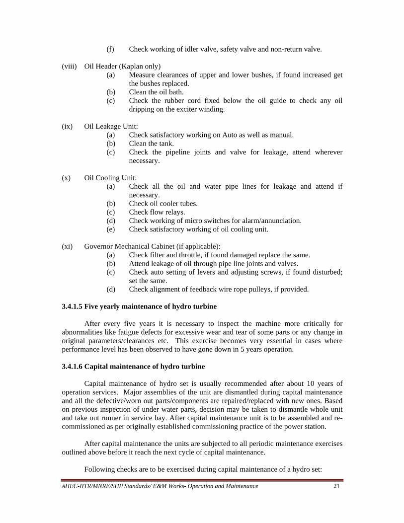
(f) Check working of idler valve, safety valve and non-return valve. (viii) Oil Header (Kaplan only)
(a) Measure clearances of upper and lower bushes, if found increased get the bushes replaced.
(b) Clean the oil bath. (c) Check the rubber cord fixed below the oil guide to check any oil
dripping on the exciter winding. (ix) Oil Leakage Unit:
(a) Check satisfactory working on Auto as well as manual. (b) Clean the tank. (c) Check the pipeline joints and valve for leakage, attend wherever
necessary. (x) Oil Cooling Unit:
(a) Check all the oil and water pipe lines for leakage and attend if necessary.
(b) Check oil cooler tubes. (c) Check flow relays. (d) Check working of micro switches for alarm/annunciation. (e) Check satisfactory working of oil cooling unit.
(xi) Governor Mechanical Cabinet (if applicable):
(a) Check filter and throttle, if found damaged replace the same. (b) Attend leakage of oil through pipe line joints and valves. (c) Check auto setting of levers and adjusting screws, if found disturbed;
set the same. (d) Check alignment of feedback wire rope pulleys, if provided.
3.4.1.5 Five yearly maintenance of hydro turbine
After every five years it is necessary to inspect the machine more critically for abnormalities like fatigue defects for excessive wear and tear of some parts or any change in original parameters/clearances etc. This exercise becomes very essential in cases where performance level has been observed to have gone down in 5 years operation.
3.4.1.6 Capital maintenance of hydro turbine
Capital maintenance of hydro set is usually recommended after about 10 years of operation services. Major assemblies of the unit are dismantled during capital maintenance and all the defective/worn out parts/components are repaired/replaced with new ones. Based on previous inspection of under water parts, decision may be taken to dismantle whole unit and take out runner in service bay. After capital maintenance unit is to be assembled and re-commissioned as per originally established commissioning practice of the power station.
After capital maintenance the units are subjected to all periodic maintenance exercises outlined above before it reach the next cycle of capital maintenance.
Following checks are to be exercised during capital maintenance of a hydro set:
AHEC-IITR/MNRE/SHP Standards/ E&M Works- Operation and Maintenance 22
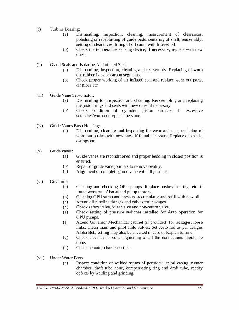
(i) Turbine Bearing: (a) Dismantling, inspection, cleaning, measurement of clearances,
polishing or rebabbitting of guide pads, centering of shaft, reassembly, setting of clearances, filling of oil sump with filtered oil.
(b) Check the temperature sensing device, if necessary, replace with new ones.
(ii) Gland Seals and Isolating Air Inflated Seals: (a) Dismantling, inspection, cleaning and reassembly. Replacing of worn
out rubber flaps or carbon segments. (b) Check proper working of air inflated seal and replace worn out parts,
air pipes etc.
(iii) Guide Vane Servomotor: (a) Dismantling for inspection and cleaning. Reassembling and replacing
the piston rings and seals with new ones, if necessary. (b) Check condition of cylinder, piston surfaces. If excessive
scratches/worn out replace the same.
(iv) Guide Vanes Bush Housing: (a) Dismantling, cleaning and inspecting for wear and tear, replacing of
worn out bushes with new ones, if found necessary. Replace cup seals, o-rings etc.
(v) Guide vanes: (a) Guide vanes are reconditioned and proper bedding in closed position is
ensured. (b) Repair of guide vane journals to remove ovality. (c) Alignment of complete guide vane with all journals.
(vi) Governor:
(a) Cleaning and checking OPU pumps. Replace bushes, bearings etc. if found worn out. Also attend pump motors.
(b) Cleaning OPU sump and pressure accumulator and refill with new oil. (c) Attend oil pipeline flanges and valves for leakages. (d) Check safety valve, idler valve and non-return valve. (e) Check setting of pressure switches installed for Auto operation for
OPU pumps. (f) Attend Governor Mechanical cabinet (if provided) for leakages, loose
links. Clean main and pilot slide valves. Set Auto rod as per designs Alpha Beta setting may also be checked in case of Kaplan turbine.
(g) Check electrical circuit. Tightening of all the connections should be done.
(h) Check actuator characteristics.
(vii) Under Water Parts (a) Inspect condition of welded seams of penstock, spiral casing, runner
chamber, draft tube cone, compensating ring and draft tube, rectify defects by welding and grinding.
AHEC-IITR/MNRE/SHP Standards/ E&M Works- Operation and Maintenance 23
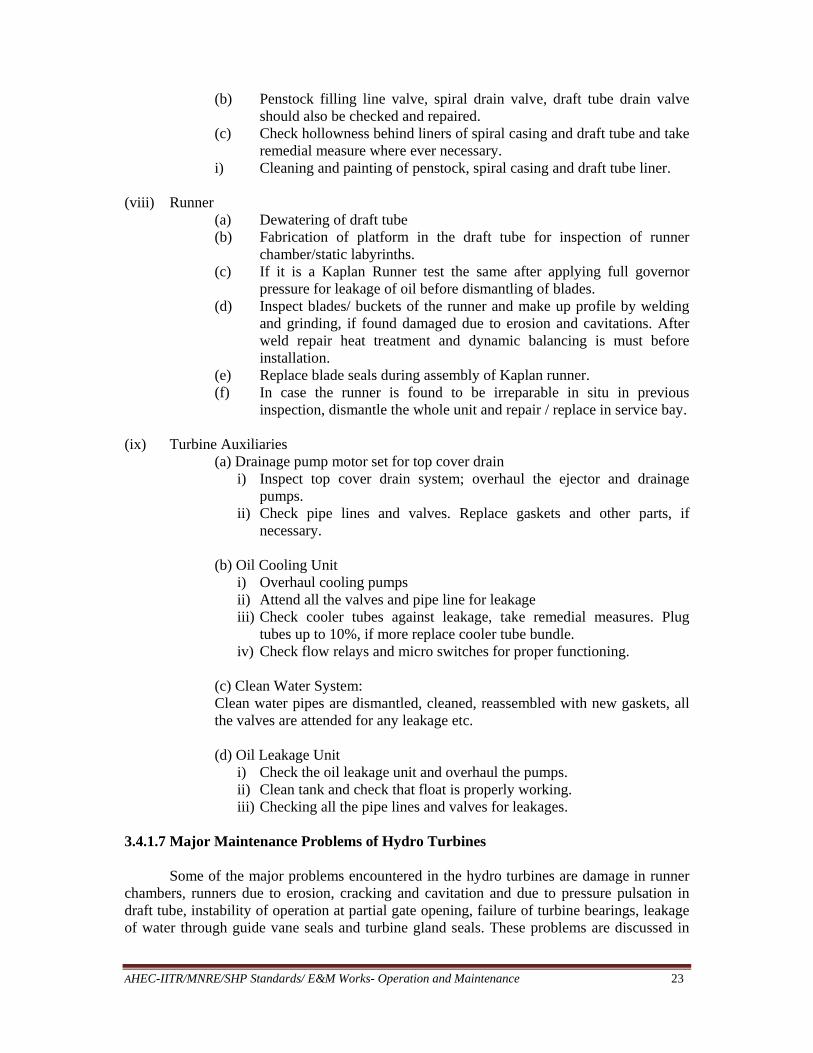
(b) Penstock filling line valve, spiral drain valve, draft tube drain valve should also be checked and repaired.
(c) Check hollowness behind liners of spiral casing and draft tube and take remedial measure where ever necessary.
i) Cleaning and painting of penstock, spiral casing and draft tube liner. (viii) Runner
(a) Dewatering of draft tube (b) Fabrication of platform in the draft tube for inspection of runner
chamber/static labyrinths. (c) If it is a Kaplan Runner test the same after applying full governor
pressure for leakage of oil before dismantling of blades. (d) Inspect blades/ buckets of the runner and make up profile by welding
and grinding, if found damaged due to erosion and cavitations. After weld repair heat treatment and dynamic balancing is must before installation.
(e) Replace blade seals during assembly of Kaplan runner. (f) In case the runner is found to be irreparable in situ in previous
inspection, dismantle the whole unit and repair / replace in service bay. (ix) Turbine Auxiliaries
(a) Drainage pump motor set for top cover drain i) Inspect top cover drain system; overhaul the ejector and drainage
pumps. ii) Check pipe lines and valves. Replace gaskets and other parts, if
necessary.
(b) Oil Cooling Unit i) Overhaul cooling pumps ii) Attend all the valves and pipe line for leakage iii) Check cooler tubes against leakage, take remedial measures. Plug
tubes up to 10%, if more replace cooler tube bundle. iv) Check flow relays and micro switches for proper functioning.
(c) Clean Water System: Clean water pipes are dismantled, cleaned, reassembled with new gaskets, all the valves are attended for any leakage etc. (d) Oil Leakage Unit
i) Check the oil leakage unit and overhaul the pumps. ii) Clean tank and check that float is properly working. iii) Checking all the pipe lines and valves for leakages.
3.4.1.7 Major Maintenance Problems of Hydro Turbines
Some of the major problems encountered in the hydro turbines are damage in runner chambers, runners due to erosion, cracking and cavitation and due to pressure pulsation in draft tube, instability of operation at partial gate opening, failure of turbine bearings, leakage of water through guide vane seals and turbine gland seals. These problems are discussed in

AHEC-IITR/MNRE/SHP Standards/ E&M Works- Operation and Maintenance 24
detailed in the following paragraphs. Fig 1 to Fig 6 show severe damage to different types of vital turbine components.
Fig 1: Eroded Buckets of Pelton Runner
Fig 2: Eroded Niddle

AHEC-IITR/MNRE/SHP Standards/ E&M Works- Operation and Maintenance 25
Fig 3: Eroded Kaplan Runner Blade
Fig 4: Eroded Francis Runner

AHEC-IITR/MNRE/SHP Standards/ E&M Works- Operation and Maintenance 26
Fig 5: Runner Cavitation
Fig 6: Guidevane Cavitation
A. Runner 1. Erosion due to silt
The problem of erosion of turbine runners, guide vanes and other under water parts has assumed serious proportions especially in some of the run-of-river schemes, The rivers in
AHEC-IITR/MNRE/SHP Standards/ E&M Works- Operation and Maintenance 27
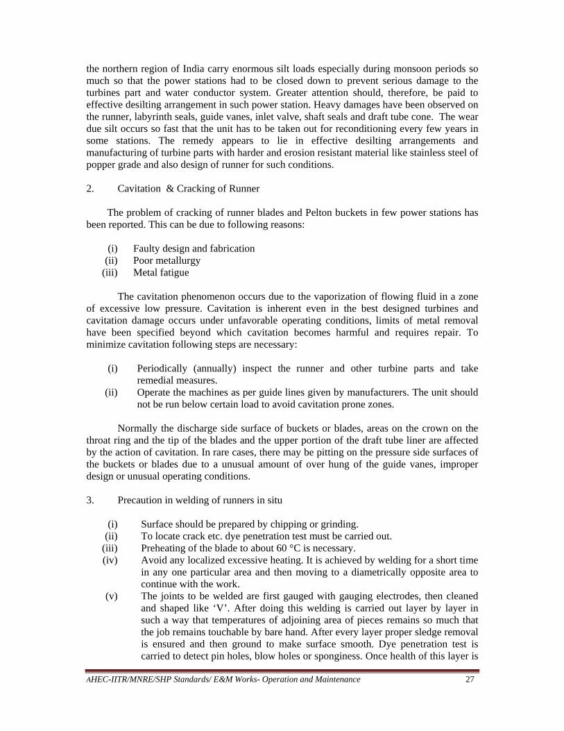
the northern region of India carry enormous silt loads especially during monsoon periods so much so that the power stations had to be closed down to prevent serious damage to the turbines part and water conductor system. Greater attention should, therefore, be paid to effective desilting arrangement in such power station. Heavy damages have been observed on the runner, labyrinth seals, guide vanes, inlet valve, shaft seals and draft tube cone. The wear due silt occurs so fast that the unit has to be taken out for reconditioning every few years in some stations. The remedy appears to lie in effective desilting arrangements and manufacturing of turbine parts with harder and erosion resistant material like stainless steel of popper grade and also design of runner for such conditions.
2. Cavitation & Cracking of Runner
The problem of cracking of runner blades and Pelton buckets in few power stations has been reported. This can be due to following reasons:
(i) Faulty design and fabrication
(ii) Poor metallurgy (iii) Metal fatigue
The cavitation phenomenon occurs due to the vaporization of flowing fluid in a zone
of excessive low pressure. Cavitation is inherent even in the best designed turbines and cavitation damage occurs under unfavorable operating conditions, limits of metal removal have been specified beyond which cavitation becomes harmful and requires repair. To minimize cavitation following steps are necessary:
(i) Periodically (annually) inspect the runner and other turbine parts and take
remedial measures. (ii) Operate the machines as per guide lines given by manufacturers. The unit should
not be run below certain load to avoid cavitation prone zones.
Normally the discharge side surface of buckets or blades, areas on the crown on the throat ring and the tip of the blades and the upper portion of the draft tube liner are affected by the action of cavitation. In rare cases, there may be pitting on the pressure side surfaces of the buckets or blades due to a unusual amount of over hung of the guide vanes, improper design or unusual operating conditions.
3. Precaution in welding of runners in situ
(i) Surface should be prepared by chipping or grinding.
(ii) To locate crack etc. dye penetration test must be carried out. (iii) Preheating of the blade to about 60 °C is necessary. (iv) Avoid any localized excessive heating. It is achieved by welding for a short time
in any one particular area and then moving to a diametrically opposite area to continue with the work.
(v) The joints to be welded are first gauged with gauging electrodes, then cleaned and shaped like ‘V’. After doing this welding is carried out layer by layer in such a way that temperatures of adjoining area of pieces remains so much that the job remains touchable by bare hand. After every layer proper sledge removal is ensured and then ground to make surface smooth. Dye penetration test is carried to detect pin holes, blow holes or sponginess. Once health of this layer is

AHEC-IITR/MNRE/SHP Standards/ E&M Works- Operation and Maintenance 28
ensured then second layer of weld deposit is done. For every layer grinding and dye penetration is required till the required weld deposit is achieved for joining the adjoining pieces. Principle of “weld little, cool more” is followed and only boiler quality welders are engaged for the job.
(vi) Plenty of time should be allowed for the welded area to cool down since forced cooling may cause distortion due to locked in stresses. Hot peening (hitting with mallet) is also must for relieving locked stresses.
(vii) A close check of runner to runner chamber/ labyrinths clearances should be made at least two to three times per day during the repair of runner.
(viii) Templates should be prepared to check and obtain runner profile. (ix) After welding all the welded areas should be properly ground to match with the
desired profile. (x) Dye penetration test/ ultra sonic test should once again be carried out to ensure
crack free welding. Rectification, if necessary, should be done.
If extensive welding on the runner is required, it will be desirable to take out the runner and repair the same as per advice of manufacturer and also to get heat treatment done. Static as well dynamic balancing of the rotating parts also becomes necessary before re-commissioning to prevent problem of cracking of blades and excessive vibrations in machines.
B. Turbine Guide Bearing
A number of turbine guide bearing designs are in use. These may be classified as follows:
(i) Plain water cooled bearing.
(ii) Bath type with circular cooling tubes. (iii) Bath type with cooling water tubes embedded in the pads. (iv) Grease lubricated bearing.
In the case of plain water cooled bearings, either ferrobestos or rubber lined pads are
used against a welded shaft sleeve. The ferrobestos lined bearing have given considerable trouble at one of the power station and these had to be replaced by rubber lined pads.
Small diameter cooling pipes embedded in bearing pads have a tendency to clog especially at the time of high silt contents resulting in water starvation.
Complaints of excessive oil splashing have been received about the rotating bath type bearing. Grease lubrication bearings have a tendency to clog when in contact with the water and it is very essential to use grease with the right type of properties.
A number of cases of turbine guide bearing failures have come to notice. These are:
(i) Starvation of oil in the bath. (ii) Inadequate cooling water due to clogging of pipe.
(iii) Mal-functioning of instrument like RTDs, TSDs, oil level and flow relays etc. (iv) Damage of cooling tubes.

AHEC-IITR/MNRE/SHP Standards/ E&M Works- Operation and Maintenance 29
C. Gland Seals Normally two types of shaft gland seals are in use in different power stations:
(i) Carbon or Ferrobestos segment. (ii) Rubber flap.
(i) Carbon or Ferrobestos Segment
The seal segments are housed in the stuffing box. Stuffing box being always in touch with the shaft is subjected to excessive wear and tear. The overhauling of the stuffing box becomes necessary when it is observed that consumption of cooling water has considerably increased or excessive water in top cover appears to be coming. In general maintenance of the seal is required to be done annually.
In the event of breakage or damage to a carbon segment it is advisable to replace the whole set of carbon segments. In very rare case only the damaged segment is replaced, care must be taken to ensure that the axial thickness of the new segments falls within the limit size to ±0.002” of the existing ring to which it is to be fitted.
All carbon segments and spacers are fitted to place and match marked on assembly. Whenever any part is replaced it should be ensured that match marking after final assembly is done. Whenever reassembly of the gland seal with existing gland ring or new ring is done it is importance to ensure:
(a) All carbon/Ferrobestos segments are carefully examined for any chipping or
damage.
(b) All stainless steel facings are flat and square with the gland sleeve and there are no steps at the facing joints.
(c) Ensure proper fixing of shaft sleeve on shaft by bolts/studs dowels etc
(d) Stainless steel facing and sleeve are completely free from grease.
(e) Ensure proper bedding of segments with shaft sleeve.
(f) All segment to segment and segment to stainless steel mating surfaces are perfect.
(g) All garter springs are assembled to obtain even tension all around.
(h) Alignment of segments in the lower assembly is carefully checked with a hard wooden peg or similar device before fitting retaining pins.
(ii). Rubber flap
Maintenance of rubber flap type gland seal is comparatively simpler and easier. Only precaution during assembly of rubber gland is jointing of the rubber seal in the proper way.
The quality of rubber used plays a very important role for satisfactory performance of the rubber gland.
The shaft sleeve should also be checked, it should be circular and smooth and properly secured on the shaft.

AHEC-IITR/MNRE/SHP Standards/ E&M Works- Operation and Maintenance 30
D. Guide vane servomotor
Normally main source of trouble is rubber cup seals which need to be replaced after a few years. Rubber seals should be replaced during capital maintenance. It is important that all the parts are match marked before dismantling so that reassembly is correctly done.
E. Governor
Different types of governors are in use in different hydro power stations.
Manufacturer’s O&M manual is to be strictly followed as these are critical items.
F. Governing Oil System
The oil sump should be properly cleaned and filled with filtered/fresh oil. The oil samples should be got tested for verification of the desired properties. Regular centrifuging of oil with the help of De-Laval type oil purifying machine would go a long way in enhancing the life of the oil.
During annual overhauling OPU sump and pressure accumulator should be completely emptied and cleaned. The strainers should be inspected and repaired, if necessary. The OPU pumps require maintenance when they develop excessive noise or vibration. This may be due to some worn out bearing, screw/ impeller and body of the pump which would be replaced. Some time oil level in sump is found decreased which may be due to system leakages in the systems which are required to be attended.
One more problem which has been faced in different power station is entry of water in the governing oil system. From following two sources the water can enter in the governing oil system.
(i) From top cover, through oil leakage pumps which caters leakage of servo motor
oil. Its sump being located well below the level of servo motors in the top cover may not be properly sealed, thus providing access to the top cover water which may ultimately be delivered to the OPU sump.
(ii) In case of Kaplan turbine water may enter into the runner hub through rubber seal of blades.
To eliminate first possibility the oil leakage unit delivery should be isolated from the
OPU sump and connected to a separate tank.
But for the second possibility there is no way except replacing blade seals, if excessive water found in the Governor oil.
Periodical check of the OPU sump oil sample for moisture content by carrying out crackle test where problem of water entry is frequent is the only way to keep track of such possibility.

AHEC-IITR/MNRE/SHP Standards/ E&M Works- Operation and Maintenance 31
G. Oil Header
In Kaplan turbine the oil header is required to supply governing oil to the runner servomotor and return oil to the OPU sump. Oil header has an oil guide connected with the rotating and servo tube. The servo tube has ports to receive return oil deliver the same to the pipes coming from OPU sump. This tube is guided by three sets of bushes in the oil tube. Due to run out of the shaft these bushes press the servo tube which may cause failure of the same.
Monitoring of wobbling of the servo tube with help of dial indicator may provide a guide line and save the bushes from further wearing. Remedial measures to reduce run out of the servo tube must be taken at this stage.
At the time of assembly of various parts of header, proper match marking and dowelling is essential so that reassembly may be correctly done.
3.4.2 Preventive Maintenance of Hydro Generator (Periodical Maintenance) Preventive maintenance ensures a long trouble free operation of the generator. Given in the following table are the recommended daily, monthly, quarterly, half yearly & yearly maintenance checks to be conducted on the generator. While it is appreciated that it is not always possible to rightly follow this schedule due to generator loading constraints, the recommendation given in Table 1 may be taken as a guide line and these may be altered slightly, based on the past experience.
Table 1: Periodical Maintenance of Hydro Generator
S. No. Description Periodicity Remarks 1.00 Stator 1.01 Temperature record on log sheet for core
and winding, hot and cold air. Hourly
1.02 Visual inspection of the overhang parts of the stator winding.
Half yearly
1.03 Checking the fixing of winding, condition of winding joints with bus bars etc.
Half yearly
1.04 Clean the winding with dry & clean compressed air (2 to 3 kg/cm2).
Half yearly Cleaning to be done such that the dust does not collect in side machine.
1.05 Check overhang parts of stator winding, bus bars, inner periphery of stator core (if possible), parts of stator winding in slots (specially at sector joint) binding & spacers between the winding bars/bandage rings.
Yearly
1.06 Check looseness of overhang, bus bars slot wedges etc.
Yearly
1.07 Check the fixing of stator active iron( core) with the frame body in all possible
Yearly

AHEC-IITR/MNRE/SHP Standards/ E&M Works- Operation and Maintenance 32
S. No. Description Periodicity Remarks places. If it is necessary, tighten the studs of pressing plates.
1.08 Check pins & fixing of stator with foundations.
Yearly
1.09 Check D.C. resistance, IR & PI value. Yearly Record to be maintained
1.10 Check functioning of RTDs of stator. Yearly -do- 1.11 Blow the winding, active iron and
bandage rings etc. with dry & clean compressed air (2 to 3 kg/cm2).
Yearly
1.12 After cleaning apply Red-gel coat on the overhang.
Yearly
1.13 In case of excessive wetting of stator winding during conditions such as flooding, drying of winding by passing current is not allowed initially as electrolysis of water may take place. This is harmful to the winding.
As per requirement
External heating arrangement is to be provided till wetness is removed
2.00 ROTOR: 2.01 Check rotor winding and insulation
condition of current carrying leads. Yearly
2.02 Check the condition of inter-polar connections
Yearly
2.03 Check the condition of damper winding. Yearly 2.04 Check the locking of pole wedges. If
required carryout additional wedging. Yearly
2.05 Check locking of rim wedges Yearly In case the wedges are loose contact manufacturer before attempting any rectification.
2.06 Check the gaps of spider arms, brake track.
Yearly
2.07 Check tightening & proper locking of all fasteners.
Yearly
2.08 Clean rotor from dust by blowing compressed air free from moisture (2 to 3 kg/cm2).
Yearly
2.09 Measure D.C. resistance and IR value of rotor winding.
Yearly Keep a record
2.10 Check the pole coils for inter-turn fault. Yearly . 3.00 Slip ring & Brush Rocker 3.01 Check sparking. Every shift 3.02 Check pitting & Grooving of slip ring Quarterly In case of excessive
grooving rectify by grinding.
3.03 Check IR value of rotor through slip rings before & after cleaning slip rings.
Half yearly Keep a record

AHEC-IITR/MNRE/SHP Standards/ E&M Works- Operation and Maintenance 33
S. No. Description Periodicity Remarks 3.04 Clean the brush rocker, brushes, slip
rings and the surrounding areas. Monthly Special care be taken
to clear carbon dust from ‘V’ shaped insulation pieces fitted between slip rings.
3.05 Check spring tension Quarterly Use a precision spring balance for adjusting spring tension. The carbon brushes can be used till it is not possible to measure/ adjust spring tension.
3.06 Check for absence of oil or its vapors in slip ring area.
Every shift. Oil leakages, if any, to be removed.
3.07 Check distance of brush holder from slip ring and keep it as specified in the drawing.
Monthly
3.08 New brushes of proper grade to be used after bedding the brushes. The brush should not be too tight/loose inside the holder.
While replacing
3.09 Ensure use of same & recommended grade of carbon brushes on one machine.
While replacing
3.10 Check all fasteners of slip rings, brush rocker & current carrying lead.
Half Yearly
3.11 Check carbon brushes for absence of pitting and severe wear & tear.
Quarterly In case the damage is excessive, replace complete set.
3.12 Inter change polarity of slip rings (if provision exists).
Yearly
3.13 Carryout thorough cleaning of slip ring area. Stop oil vapours in this area.
Yearly
3.14 In case the original insulating enamel is peeling off remove the balance enamel and apply fresh enamel.
Yearly While cleaning avoid using insulating paint removers.
3.15 Check wobbling at slip rings. At the time of installation/ during major overhauling
4.00 Thrust Bearing 4.01 Measurement of temperatures of T.B.
Pad & Oil by RTD & TSD and record on log sheet.
Hourly
4.02 Check & record reading of oil level. Once in a shift 4.03 Analysis of oil from oil bath. Half yearly Record to be kept. 4.04 Change of oil in T.B. oil bath. When

AHEC-IITR/MNRE/SHP Standards/ E&M Works- Operation and Maintenance 34
S. No. Description Periodicity Remarks centrifuging doesn’t help in improving its quality up to acceptable values.
4.05 Check level of oil from the gauge glass. Any increase in level may be due to leakage of water in the oil bath coolers.
Once in every shift.
Unit should be stopped in case of leakage from cooling tube, plugging of cooling tubes upto 10% can be done depending upon bearing temperature.
4.06 Measures insulation resistance of T.B. disc.
Yearly
4.07 Check calibration of the TSD’s & RTD’s of thrust bearing.
Yearly
4.08 Check the working surface of thrust bearing pads, scrapping, if required, should be carried out with respect to T.B. disc after applying Molisulf grease on the pads & giving rotation to the unit. Load sharing on T.B. pads and the verticality of the unit is to be checked thereafter.
Yearly
4.09 Check the condition of mirror surface of T.B. Disc. Polishing of the surface can be done to remove minor scratches.
During capital maintenance
This will require partial dismantling of unit.
4.10 Clean all inner surfaces of oil bath from dust, wash them with Kerosene and dry with clean cloth.
Once in Two years.
Oil bath is to be finally flushed with fresh turbine oil; to be discarded after
use. 4.11 Check the condition of weld seam of oil
bath & oil pipe lines for leakages visually.
Yearly
4.12 Check the condition of insulation of RTD leads.
Yearly
4.13 Check if excessive foaming is taking place on oil through gauge glass. This is normally due to mixing of water leaking from oil coolers. If oil level is not rising, the oil may need de-foaming. Oil sample to be checked.
As required Watch carefully for rise in water level to confirm leakage and attend accordingly.
4.14 Check if any insulating segment over T.B. disc is displaced.
During capital maintenance
4.15 Check (in case of problem) the intactness of spherical surface of thrust bolt.
As per requirement.
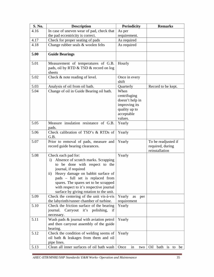
AHEC-IITR/MNRE/SHP Standards/ E&M Works- Operation and Maintenance 35
S. No. Description Periodicity Remarks 4.16 In case of uneven wear of pad, check that
the pad eccentricity is correct. As per requirement.
4.17 Check for proper seating of pads As required 4.18 Change rubber seals & woolen felts
As required
5.00 Guide Bearings
5.01 Measurement of temperatures of G.B. pads, oil by RTD & TSD & record on log sheets
Hourly
5.02 Check & note reading of level. Once in every shift
5.03 Analysis of oil from oil bath. Quarterly Record to be kept. 5.04 Change of oil in Guide Bearing oil bath. When
centrifuging doesn’t help in improving its quality up to acceptable values.
5.05 Measure insulation resistance of G.B. pads.
Yearly
5.06 Check calibration of TSD’s & RTDs of G.B.
Yearly
5.07 Prior to removal of pads, measure and record guide bearing clearances.
Yearly To be readjusted if required, during reinstallation
5.08 Check each pad for: i) Absence of scratch marks. Scrapping
to be done with respect to the journal, if required
ii) Heavy damage on babbit surface of pads – full set is replaced from spares. The spares set to be scrapped with respect to it’s respective journal surface by giving rotation to the unit.
Yearly
5.09 Check the centering of the unit vis-à-vis the labyrinth/runner chamber of turbine.
Yearly as per requirement
5.10 Check the friction surface of the bearing journal. Carryout it’s polishing, if necessary.
Yearly
5.11 Wash pads & journal with aviation petrol and then carryout assembly of the guide bearing.
Yearly
5.12 Check the condition of welding seems of oil bath & leakages from them and oil pipe lines.
Yearly
5.13 Clean all inner surfaces of oil bath wash Once in two Oil bath is to be
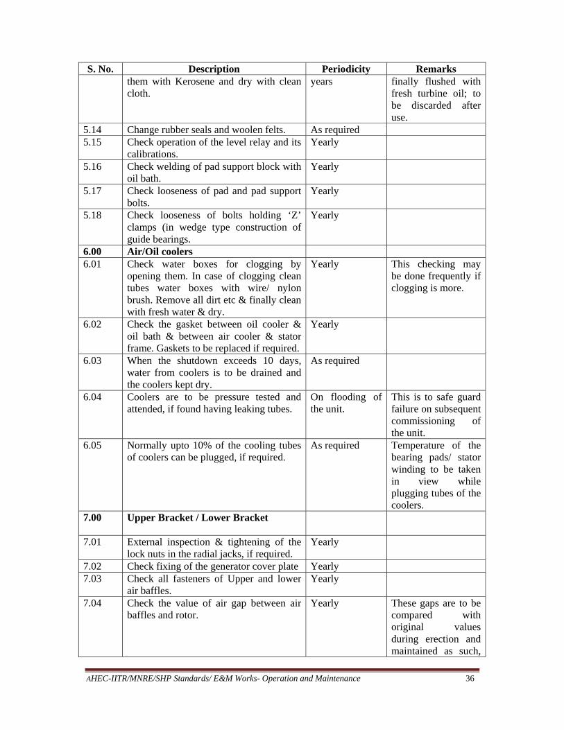
AHEC-IITR/MNRE/SHP Standards/ E&M Works- Operation and Maintenance 36
S. No. Description Periodicity Remarks them with Kerosene and dry with clean cloth.
years finally flushed with fresh turbine oil; to be discarded after use.
5.14 Change rubber seals and woolen felts. As required 5.15 Check operation of the level relay and its
calibrations. Yearly
5.16 Check welding of pad support block with oil bath.
Yearly
5.17 Check looseness of pad and pad support bolts.
Yearly
5.18 Check looseness of bolts holding ‘Z’ clamps (in wedge type construction of guide bearings.
Yearly
6.00 Air/Oil coolers 6.01 Check water boxes for clogging by
opening them. In case of clogging clean tubes water boxes with wire/ nylon brush. Remove all dirt etc & finally clean with fresh water & dry.
Yearly This checking may be done frequently if clogging is more.
6.02 Check the gasket between oil cooler & oil bath & between air cooler & stator frame. Gaskets to be replaced if required.
Yearly
6.03 When the shutdown exceeds 10 days, water from coolers is to be drained and the coolers kept dry.
As required
6.04 Coolers are to be pressure tested and attended, if found having leaking tubes.
On flooding of the unit.
This is to safe guard failure on subsequent commissioning of the unit.
6.05 Normally upto 10% of the cooling tubes of coolers can be plugged, if required.
As required Temperature of the bearing pads/ stator winding to be taken in view while plugging tubes of the coolers.
7.00 Upper Bracket / Lower Bracket
7.01 External inspection & tightening of the lock nuts in the radial jacks, if required.
Yearly
7.02 Check fixing of the generator cover plate Yearly 7.03 Check all fasteners of Upper and lower
air baffles. Yearly
7.04 Check the value of air gap between air baffles and rotor.
Yearly These gaps are to be compared with original values during erection and maintained as such,

AHEC-IITR/MNRE/SHP Standards/ E&M Works- Operation and Maintenance 37
S. No. Description Periodicity Remarks if required.
7.05 Clean the brackets of dirt & dust. Yearly Cleaning can be done more often if possible.
7.06 Check fastening between upper bracket & stator and foundation plates.
Yearly
7.07 Check foundation bolts tightening for stator & lower bracket.
Yearly
7.08 Check all fasteners for locking / tightness Yearly 8.00 Overhauling of Brake System Yearly 8.01 Record air pressure available at brake
panel. Every shift Record on log sheet
8.02 Check thickness of brake pad Yearly or as required
Record to be maintained along with number of braking in the period with Air pressure used for braking.
8.03 Measure: i) Time for unit to come to braking
speed from rated speed after signaling the unit to stop.
ii) Check time for unit to stop after applying brakes
During first spinning / yearly
Record to be kept. In case if this time has increased abnormal then look for increased guide vanes clearances. Presence of oil on brake track or reduction in air pressure etc. affect the time
8.04 Check if excessive brake dust is generated and find its cause.
Yearly Clean the affected areas periodically as required
8.05 During jacking operation lifting of the rotor is to be limited to the specified value
During jacking Limit switch to be suitably mounted to check the rotor lift.
8.06 Keep the unit on jacks which are mechanically locked if closure of machine is for more than 24 hours
As required
8.07 After each jacking operation ensure cleaning of pipe with air under pressure as provided in the system.
As required
8.08 Check no oil leaks from return pipe line during jacking operation
As required
8.09 Check function of the braking system on manual & auto and the operation of the limit switches of brakes. Check leakage through pipelines during braking.
Yearly Record is maintained. In case of any problem brake panel & brakes are to be checked &

AHEC-IITR/MNRE/SHP Standards/ E&M Works- Operation and Maintenance 38
S. No. Description Periodicity Remarks rectified as required.
8.10 Check all fasteners of brakes and brake pipe lines & gaskets wherever provided.
Yearly
8.11 Check the condition of brake track and its holding with the rotor.
Yearly
8.12 Open brake cum jack assembly. Clean the inner surface of dust with Kerosene & reassemble.
Yearly Replace the gasket, if required.
9.00 General
9.01 External examination of parts of generator which are accessible.
Once in each shift
9.02 External inspection of air coolers, oil coolers, pipe lines, sealing & control valve etc. for leakages.
Once in each shift
9.03 Ensure cleanliness of all external accessible parts of the generator & wipe with clean & dry cloth.
Once in each shift
9.04 Check wobbling of the shaft at turbine generator flange/ TGB.
Yearly before taking shut down
9.05 Blow with compressed air the internal surface of the generator.
Monthly
9.06 External inspection of current carrying leads PMG, Bus Bars, Terminal Blocks, Panels etc.
Monthly To be cleaned if necessary
9.07 Check the condition of lighting inside the barrel
Monthly
9.08 Check the vibrations at TGB, UGB & LGB at predetermined points.
Yearly before taking shut down
9.09 Check connections of current carrying leads & cables. Tighten the bolts, if required, after removing the insulation.
Yearly
9.10 Check the calibration of Electrical measuring instruments i.e. voltmeter, ammeter, Active/ Reactive Power meter. Frequency meter, P.F. meter for Stator output, Voltmeter & Ammeter in Field winding circuit, energy meter etc.
Yearly
9.11 Check the Sensitivity & Stability of Generator Electrical Protection scheme.
Yearly
9.12 Check the working of Fire Extinguishing CO2 system without actually releasing the CO2 gas on manual and on auto operation as per the instructions provided in O&M manual of the Fire
Yearly

AHEC-IITR/MNRE/SHP Standards/ E&M Works- Operation and Maintenance 39
S. No. Description Periodicity Remarks Extinguishing System provided by its supplier.
9.13 Check the characteristics of Static Excitation system in both auto & manual mode and sensitivity of various limits.
As specified in its O&M manual.
10.00 Oil pipe line/ external oil cooling system (if applicable)
10.01 Check oil pressure at the pump across the filter & point of entry to the bearing.
Every shift Record is to be maintained.
10.02 Check the operation of the electrical contact pressure gauge.
Monthly
10.03 Check temperature of bearings of AC/DC Pump-motor set for flow of oil cooling system.
Monthly This temp. is not to exceed the specified limits. In case temp. is excessive check if lubricating grease is filled as required.
10.04 Check conditions of gland packing of the pump and see that air is not being sucked from here into the system.
Monthly .
10.05 Completely clean the oil tank & T.B. oil bath
Yearly
10.06 Clean the oil pipe line after disconnecting it
Yearly
10.07 Check the operation of the valves of the pipe line.
Yearly
10.08 Check the Operation of D.C. pump motor set (if provided)
Monthly
10.09 Check the temperature of cold & hot water.
Hourly Keep record in the log sheet.
10.10 Check the air ventilation cock of the oil tank is open during operation of the unit.
During start of the unit/ during each shift.
10.11 Check pipe line for leakage of oil. Once in each shift.
10.12 Check oil sample for acidity, viscosity, moisture content, foreign material & sludge. formations.
Yearly or as required
Separate oil sample from each bearing should be sent for chemical analysis & record to be kept.
10.13 Clean holes for oil entry into the T.B. housing
Yearly
3.4.2.1 Periodical checks
All the above checks and some more checks are again tabulated for Daily as per Table 2, Annual checks and maintenance as per Table 3.
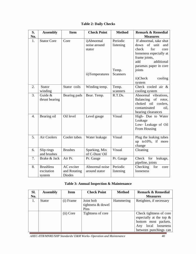
AHEC-IITR/MNRE/SHP Standards/ E&M Works- Operation and Maintenance 40
Table 2: Daily Checks
S. No.
Assembly Item Check Point Method Remark & Remedial Measures
1. Stator Core Core i)Abnormal noise around stator ii)Temperatures
Periodic listening Temp. Scanners
If abnormal, take shut down of unit and check for core looseness especially at frame joints, add additional paramax paper in core joints ii)Check cooling system
2. Stator winding
Stator coils Winding temp. Temp. scanners
Check cooled air & cooling system
3. Guide & thrust bearing
Bearing pads Bear. Temp. R.T.Ds. Abnormal vibrations, Balancing of rotor, choked oil coolers, contaminated oil, bearing clearances
4. Bearing oil Oil level Level gauge Visual High- Due to Water Leakage Low- Leakage of Oil From Housing
5. Air Coolers Cooler tubes Water leakage Visual Plug the leaking tubes up to10%, if more change
6. Slip rings and brushes
Brushes Sparking, Mix of C-Dust/ Oil
Visual Cleaning
7. Brake & Jack Air Pr. Pr. Gauge Pr. Gauge Check for leakage, pipeline, joints
8. Brushless excitation system
AC exciter and Rotating Diodes
Abnormal noise around stator
Periodic listening
Checking for core looseness
Table 3: Annual Inspection & Maintenance
Sl. No.
Assembly Item Check Point Method Remark & Remedial Measures
1. Stator (i) Frame Joint bolt tightness & dowel Pins
Hammering Retighten, if necessary
(ii) Core Tightness of core Check tightness of core especially at the top & bottom most packets. Any local looseness between punchings can

AHEC-IITR/MNRE/SHP Standards/ E&M Works- Operation and Maintenance 41
Sl. No.
Assembly Item Check Point Method Remark & Remedial Measures
be filled up with asbestos or paramax paper glued with epoxy varnish & core bolts retightened. After repairs spray the top & bottom three packets (both from I.D. & O.D.) with loctite – 290 Marketed By M/s Fit Tite Chemicals Ltd.
Core Duct Contamination Visual Clean with Dry compressed air
Stator winding
Cleanliness & general condition
Visual Clean the end windings
Measure IR/PI values after cleaning DLA/Tan-Delta measurement on full stator
Dry out if IR Value is low
2. Field winding
Field coil & rotor leads
A-General condition of coil, pole & cleanliness
Visual i-Clean the field coil with vacuum cleaner ii- Check the coil joints for any cracks overheating etc
B-Inter turn faults Measure impedance of field coils by applying 60 to 100 V AC, 50 Hz supply
If impedance of some coils is very low, those must be checked for possible inter-turn faults.
3. Brush gear and Slip rings
Brushes & Slip rings Insulated parts
General Conditions & Cleanliness
Visual The slip ring is running out, correct it, any grooves etc to be removed by oil stone, grinding or turning to prevent excessive sparking All insulated parts are to be cleaned by dry compressed air
Note: For cleaning stator ducts, stator winding, field coils, rotor leads, brush gear, use cleaning agents as recommended by manufacturer
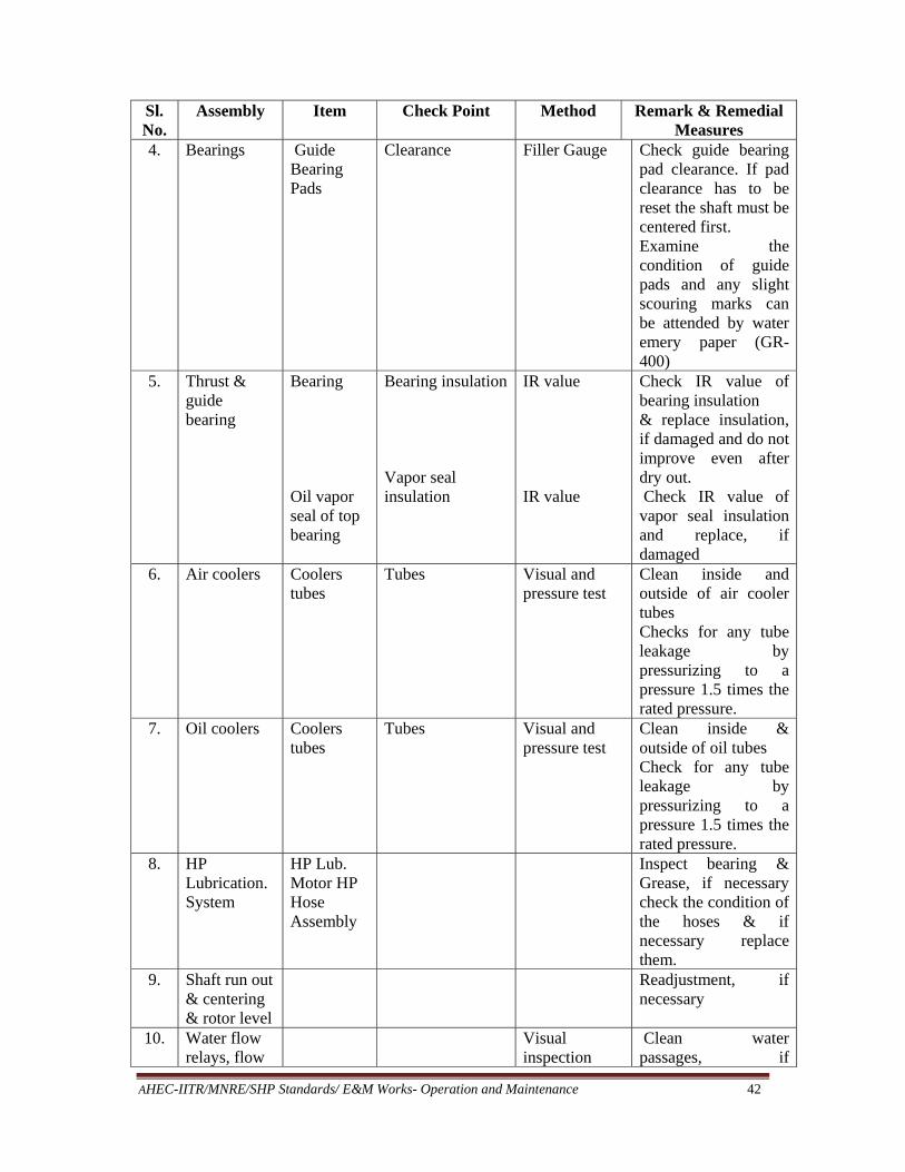
AHEC-IITR/MNRE/SHP Standards/ E&M Works- Operation and Maintenance 42
Sl. No.
Assembly Item Check Point Method Remark & Remedial Measures
4. Bearings Guide Bearing Pads
Clearance Filler Gauge Check guide bearing pad clearance. If pad clearance has to be reset the shaft must be centered first. Examine the condition of guide pads and any slight scouring marks can be attended by water emery paper (GR-400)
5. Thrust & guide bearing
Bearing Oil vapor seal of top bearing
Bearing insulation Vapor seal insulation
IR value IR value
Check IR value of bearing insulation & replace insulation, if damaged and do not improve even after dry out. Check IR value of vapor seal insulation and replace, if damaged
6. Air coolers Coolers tubes
Tubes Visual and pressure test
Clean inside and outside of air cooler tubes Checks for any tube leakage by pressurizing to a pressure 1.5 times the rated pressure.
7. Oil coolers Coolers tubes
Tubes Visual and pressure test
Clean inside & outside of oil tubes Check for any tube leakage by pressurizing to a pressure 1.5 times the rated pressure.
8. HP Lubrication. System
HP Lub. Motor HP Hose Assembly
Inspect bearing & Grease, if necessary check the condition of the hoses & if necessary replace them.
9. Shaft run out & centering & rotor level
Readjustment, if necessary
10. Water flow relays, flow
Visual inspection
Clean water passages, if

AHEC-IITR/MNRE/SHP Standards/ E&M Works- Operation and Maintenance 43
Sl. No.
Assembly Item Check Point Method Remark & Remedial Measures
indicators & flow meters
necessary, remove silt etc, Check movement of flap and electrical contacts
11. Oil level indicator
Clean rod probe
12. Braking & Jacking machine Brake track Limit switches
Inspection and overhauling Tightness Cleaning
Clean the filter element and bowl of filter, similarly clean the bowl of lubricator also, cessation of oil dripping through that sight glass is an indication that cleaning is done Tightness of dog clamps/ bolts Proper operation & cleaning
13. Electrical Connections
Pole to pole connections, Brush gear connection, RTD terminal, heater terminal connection
Electrical Joints RTDs are to be caliberated
Tightness Tighten all electrical joints Tighten all electrical joints.
14. Rotor assembly
Tightening of fasteners
Looseness of fasteners
Visual Tighten all the approachable fasteners on rotor assembly including tightening pole and rim keys & lock all of them if found loose and locks broken.
15. Rotor Shaft vibration
Slip ring and coupling
Dial gauge
Check for run out at slip ring and turbine coupling and readjust if found more than the specified value.

AHEC-IITR/MNRE/SHP Standards/ E&M Works- Operation and Maintenance 44
Sl. No.
Assembly Item Check Point Method Remark & Remedial Measures
Bracket vibration
Vibration Balancing equipment
Rebalance, if necessary
16. Rotor pole Damper system Supporting structure
Interconnection between poles Supporting structure for proper tightness Insulation provided on supporting structure
Visual By tapping & By shaking Visual
Tighten and lock properly if supporting structure found loose. Rectify, if found damaged.
17. Top shaft Current carrying leads
Tightness of clamps, general condition
Visual Repair insulation, if found damaged
18. Generator Auxiliaries
Check for proper operation
Check that these are in good working condition
19. Cooling water valves
Check for proper operation
Clean & replace glands where needed.
20. Over speed device
Electrical contacts
Visual inspection
Cleaning of electrical contacts
3.4.2.2 Capital Maintenance of Hydro Generator A. Dismantling
a) Record insulation resistance/ polarization index values of stator, rotor and exciter b) Decouple generator shaft and turbine shaft after recording guide bearing
clearances, air gaps between stator & rotor. c) Dismantle thrust bearing d) Dismantling of other components one by one in proper sequence till rotor is free
to be lifted. e) Rotor should be taken out very carefully and kept in rotor assembly pit duly bolted
with base plate. f) All stator air coolers are to be dismantled and kept for testing and repair. g) Braking & jacking units to be dismantled h) All cares are to be taken during dismantling to ensure safety of all components,
fasteners, pins and temperature sensors etc. i) Prior arrangement of required spares, T&P, special T&P, slings, D-shackles etc, is
also necessary.
AHEC-IITR/MNRE/SHP Standards/ E&M Works- Operation and Maintenance 45
B. Maintenance of Generator Components (i) Maintenance of Stator Frame
Check all joints, tightness of bolts and location pins etc. Retighten, if necessary.
(ii) Maintenance of Stator core winding
a) Tightness of core especially at the top and bottom most packets. b) Any local looseness between punchings can be filled up with paramax paper
glued with epoxy varnish & core bolt retightened. c) Carry out check for looseness of slot wedges and mouth pieces d) After repair spray top and bottom three packets with loctite-290. e) Clean core duct with dry compressed air f) Clean the ends of winding. g) Measure IR/PI value of winding after thorough cleaning. After assembly dry out
if IR/PI is low. h) Carryout Electronic Core Imperfection Detection test also to ensure healthiness
of core. i) Carry out Tan-Delta test j) After rectifying all defect and thorough cleaning of the inner bore and overhang
portion is done and winding is to be spray painted with Dr. Beck IE-82.
(iii) Maintenance of Rotor a) The rotor is to be thoroughly cleaned with dry compressed air. b) Check general condition of coil and pole, clean with dry compressed air. c) Check the coil joints for any cracks due to overheating etc. d) Check field coils and rotor leads for inter turn fault. Measure impedance of coils
by applying suitable VAC, 50 C/s. If impedance of some coil is very low (<4%) they must be checked for possible inter turn faults.
e) Shaft is to be checked specially at G.B. journals for any marks roughness or hot spots etc. Remedial measures are to be taken if marks, roughness is found.
f) Check top and bottom rotor fans, if found damaged replace the same. g) Check tightness of all the joints of rotor spider and extension arms h) Check tightness of rotor rims, pole key rim keys etc. i) After rectification of all defects and thorough cleaning, spray paint (type IE-82
of Dr. Beck) the rotor pole with insulating red gel paint. j) Keep the rotor covered with asbestos cloth to prevent deposit of dust and fire
safety. k) All safety precautions for external damage, fire etc are to be taken during
maintenance period.
(iv) Maintenance of brush gears and slip rings a) Check if there are any grooves, roughness high points use emery paper for
rectification b) Check brush gear connections, clean all the insulated parts with dry compressed
air. c) Change set of insulation.

AHEC-IITR/MNRE/SHP Standards/ E&M Works- Operation and Maintenance 46
(v) Maintenance of Bearing Guide bearings a) Check condition of Housing b) Check condition of Pads, if required, bedding is to be done c) Check pad support also. d) In case babbit material found damaged or thinned, rebabbit pads with proper
grade of white metal. e) Check insulation of pads, if found damaged replace the same. Check IR value f) Check all RTDs & TSDs and calibration of temperature indicators
(vi) Thrust Bearing
a) Check condition of pads, if found some damage to babbit material, get
rebabbiting done b) Bedding of pads to ensure removal of high points and having desired contact
area. c) Check bearing insulation by measuring IR value. Replace insulation if found
damaged. d) Check vapor seal also and replace, if found damaged e) Check condition of housing, pivot points / spherical disc/ springs of spring
mattress of thrust bearing. f) Check all pressure gauges, level indicator. g) Check all RTDs & TSDs and calibration of temperature indicators.
(vii) Maintenance of Air Coolers
a) Clean inside and outside of air cooler tubes b) Check for any tube leakage by pressurizing to a pressure 1.5 times the rated
pressure c) If more than 10% tubes are leaking change full set of tubes or change only
leaking tubes d) After repair paint the body of coolers.
(viii) Maintenance of Oil Coolers
a) Clean inside and outside of cooling tubes b) Check for any tube leakage by pressurizing to a pressure 1.5 times the rated
pressure c) Replace full set of tubes if more than 10% of total tubes are leaking.
(ix) Maintenance of H.P. Lube system a) Inspect bearings of pump motor and grease, if necessary b) Check the condition of hoses, if necessary replace c) Check for any leakages and take remedial measures. d) Check pressure gauges etc. e) Check flow relays
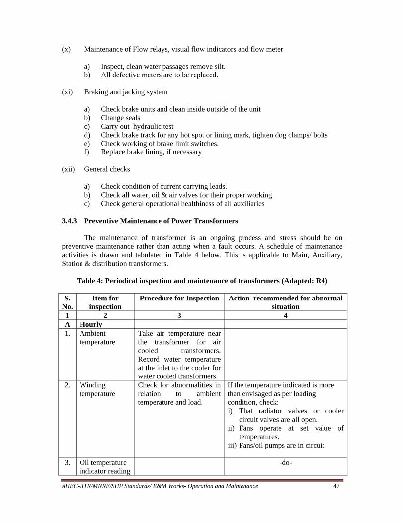
AHEC-IITR/MNRE/SHP Standards/ E&M Works- Operation and Maintenance 47
(x) Maintenance of Flow relays, visual flow indicators and flow meter a) Inspect, clean water passages remove silt. b) All defective meters are to be replaced.
(xi) Braking and jacking system
a) Check brake units and clean inside outside of the unit b) Change seals c) Carry out hydraulic test d) Check brake track for any hot spot or lining mark, tighten dog clamps/ bolts e) Check working of brake limit switches. f) Replace brake lining, if necessary
(xii) General checks
a) Check condition of current carrying leads. b) Check all water, oil & air valves for their proper working c) Check general operational healthiness of all auxiliaries
3.4.3 Preventive Maintenance of Power Transformers
The maintenance of transformer is an ongoing process and stress should be on preventive maintenance rather than acting when a fault occurs. A schedule of maintenance activities is drawn and tabulated in Table 4 below. This is applicable to Main, Auxiliary, Station & distribution transformers.
Table 4: Periodical inspection and maintenance of transformers (Adapted: R4)
S. No.
Item for inspection
Procedure for Inspection Action recommended for abnormal situation
1 2 3 4 A Hourly 1. Ambient
temperature Take air temperature near the transformer for air cooled transformers. Record water temperature at the inlet to the cooler for water cooled transformers.
2. Winding temperature
Check for abnormalities in relation to ambient temperature and load.
If the temperature indicated is more than envisaged as per loading condition, check: i) That radiator valves or cooler
circuit valves are all open. ii) Fans operate at set value of
temperatures. iii) Fans/oil pumps are in circuit
3. Oil temperature indicator reading
-do-

AHEC-IITR/MNRE/SHP Standards/ E&M Works- Operation and Maintenance 48
S. No.
Item for inspection
Procedure for Inspection Action recommended for abnormal situation
1 2 3 4 4. Load (amperes) Check against rated figures Reduce load, if it exceeds the
specified limits. 5. Voltage Correct tap position in line with
voltage. 6. Transformer/
Shunt reactor Humming and general vibration.
Check for any abnormality in sound.
Tighten any looseness in external parts. If abnormal sound still persists, complete checking is done.
B. Daily 1. Oil level in
transformer / shunt reactor
Check oil level from oil gauge glass
Top up if found low. Examine transformer/ shunt reactor for leaks. Tighten gasket joint at the leak point.
2. Oil level in diverter switch
Check oil level from the gauge glass.
If oil leakage found, check sealing gasket between diverter switch and transformer/ reactor tank. Top up oil.
3. Oil level in bushings
Check oil level from the oil gauge of the bushings in which oil remains separate from the tank oil.
If low, top up oil. Examine bushing for any oil leakage.
4. Pipe work and accessories for leakage
Check for oil leaks If leakages are observed, tighten evenly the gasket joints. Replace ‘O’ ring or washer suitably. Replace gasket, if needed.
5. Relief vent diaphragm
Check for any crack Replace, if cracked / broken. If broken, ensure from other protections provided that there is no fault inside the transformer / reactor.
6. Fans/ oil pump running
Check that fans / oil pumps are running as required.
Check connections. If found defective correct them.
7. Oil & cooling water flow.
Check oil and water flow indicators.
Check opening of valves if restricted flow observed.
C. Weekly 1. Leakage of
water into cooler Check by opening the end covers of the cooler.
Plug the tube leaking.
2. Operating sequence of oil pump and the cooler
Change over from one cooler to the other.
Ensure proper change over.
3. Operation of anti-condensation
Check anti- condensation heaters are working.
Set them right if not working
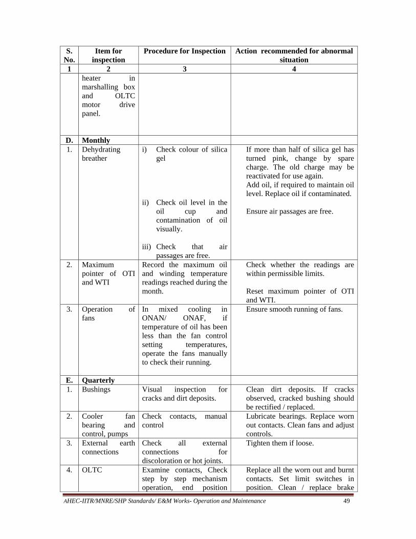
AHEC-IITR/MNRE/SHP Standards/ E&M Works- Operation and Maintenance 49
S. No.
Item for inspection
Procedure for Inspection Action recommended for abnormal situation
1 2 3 4 heater in marshalling box and OLTC motor drive panel.
D. Monthly 1. Dehydrating
breather i) Check colour of silica
gel ii) Check oil level in the
oil cup and contamination of oil visually.
iii) Check that air
passages are free.
If more than half of silica gel has turned pink, change by spare charge. The old charge may be reactivated for use again. Add oil, if required to maintain oil level. Replace oil if contaminated.
Ensure air passages are free.
2. Maximum pointer of OTI and WTI
Record the maximum oil and winding temperature readings reached during the month.
Check whether the readings are within permissible limits.
Reset maximum pointer of OTI and WTI.
3. Operation of fans
In mixed cooling in ONAN/ ONAF, if temperature of oil has been less than the fan control setting temperatures, operate the fans manually to check their running.
Ensure smooth running of fans.
E. Quarterly 1. Bushings Visual inspection for
cracks and dirt deposits. Clean dirt deposits. If cracks observed, cracked bushing should be rectified / replaced.
2. Cooler fan bearing and control, pumps
Check contacts, manual control
Lubricate bearings. Replace worn out contacts. Clean fans and adjust controls.
3. External earth connections
Check all external connections for discoloration or hot joints.
Tighten them if loose.
4. OLTC Examine contacts, Check step by step mechanism operation, end position
Replace all the worn out and burnt contacts. Set limit switches in position. Clean / replace brake
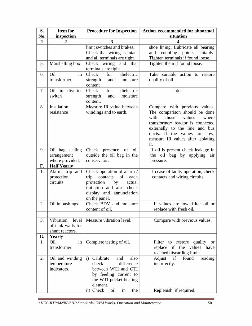
AHEC-IITR/MNRE/SHP Standards/ E&M Works- Operation and Maintenance 50
S. No.
Item for inspection
Procedure for Inspection Action recommended for abnormal situation
1 2 3 4 limit switches and brakes. Check that wiring is intact and all terminals are tight.
shoe lining. Lubricate all bearing and coupling points suitably. Tighten terminals if found loose.
5. Marshalling box Check wiring and that terminals are tight.
Tighten them if found loose.
6. Oil in transformer
Check for dielectric strength and moisture content
Take suitable action to restore quality of oil
7. Oil in diverter switch
Check for dielectric strength and moisture content.
-do-
8. Insulation resistance
Measure IR value between windings and to earth.
Compare with previous values. The comparison should be done with those values where transformer/ reactor is connected externally to the line and bus ducts. If the values are low, measure IR values after isolating it.
9. Oil bag sealing arrangement where provided.
Check presence of oil outside the oil bag in the conservator.
If oil is present check leakage in the oil bag by applying air pressure.
F. Half Yearly 1. Alarm, trip and
protection circuits
Check operation of alarm / trip contacts of each protection by actual initiation and also check display and annunciation on the panel.
In case of faulty operation, check contacts and wiring circuits.
2. Oil in bushings Check BDV and moisture content of oil.
If values are low, filter oil or replace with fresh oil.
3. Vibration level
of tank walls for shunt reactors.
Measure vibration level. Compare with previous values.
G. Yearly 1. Oil in
transformer Complete testing of oil.
Filter to restore quality or replace if the values have reached discarding limit.
2. Oil and winding temperature indicators.
i) Calibrate and also check difference between WTI and OTI by feeding current to the WTI pocket heating element.
ii) Check oil in the
Adjust if found reading incorrectly.
Replenish, if required.
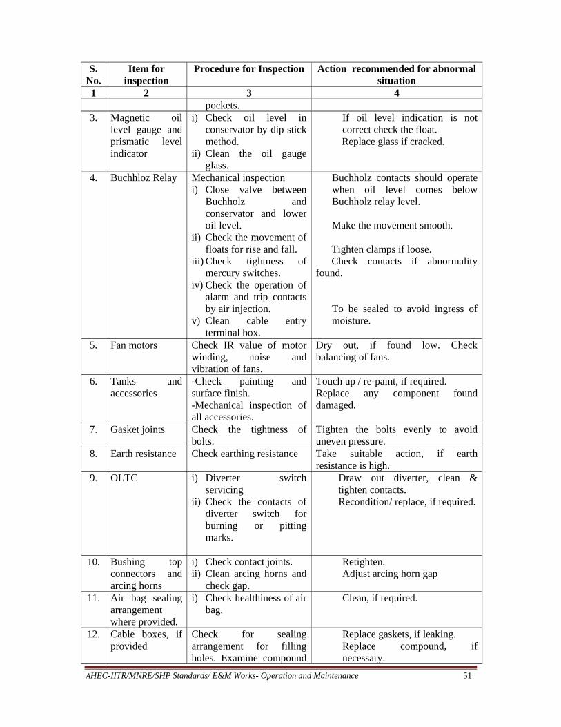
AHEC-IITR/MNRE/SHP Standards/ E&M Works- Operation and Maintenance 51
S. No.
Item for inspection
Procedure for Inspection Action recommended for abnormal situation
1 2 3 4 pockets.
3. Magnetic oil level gauge and prismatic level indicator
i) Check oil level in conservator by dip stick method.
ii) Clean the oil gauge glass.
If oil level indication is not correct check the float.
Replace glass if cracked.
4. Buchhloz Relay Mechanical inspection i) Close valve between
Buchholz and conservator and lower oil level.
ii) Check the movement of floats for rise and fall.
iii) Check tightness of mercury switches.
iv) Check the operation of alarm and trip contacts by air injection.
v) Clean cable entry terminal box.
Buchholz contacts should operate when oil level comes below Buchholz relay level.
Make the movement smooth.
Tighten clamps if loose. Check contacts if abnormality found.
To be sealed to avoid ingress of moisture.
5. Fan motors Check IR value of motor winding, noise and vibration of fans.
Dry out, if found low. Check balancing of fans.
6. Tanks and accessories
-Check painting and surface finish. -Mechanical inspection of all accessories.
Touch up / re-paint, if required. Replace any component found damaged.
7. Gasket joints Check the tightness of bolts.
Tighten the bolts evenly to avoid uneven pressure.
8. Earth resistance Check earthing resistance Take suitable action, if earth resistance is high.
9. OLTC i) Diverter switch servicing
ii) Check the contacts of diverter switch for burning or pitting marks.
Draw out diverter, clean & tighten contacts. Recondition/ replace, if required.
10. Bushing top connectors and arcing horns
i) Check contact joints. ii) Clean arcing horns and
check gap.
Retighten. Adjust arcing horn gap
11. Air bag sealing arrangement where provided.
i) Check healthiness of air bag.
Clean, if required.
12. Cable boxes, if provided
Check for sealing arrangement for filling holes. Examine compound
Replace gaskets, if leaking. Replace compound, if necessary.

AHEC-IITR/MNRE/SHP Standards/ E&M Works- Operation and Maintenance 52
S. No.
Item for inspection
Procedure for Inspection Action recommended for abnormal situation
1 2 3 4 for cracks.
13. Lightning arrestors
i) Examine for cracks and dirt deposits.
ii) Measure IR value of each stack of LAs
iii) Measurement of leakage current
Clean or replace.
In case IR value is poor, replace.
14. Off circuit tap switch
i) Move from minimum to maximum tap position & return to minimum position.
ii) Check resistance measurement at each tap.
Compare resistance values with previous results. If resistance is high, tap switch contacts to be attended to.
15. Condenser bushing
Measure power factor/ capacitance measurement.
Dry out bushing if values are abnormal and replace oil, if required.
16. Electrical tests Carry out i) Resistance
measurement at all taps for transformers with off circuit tap switch and at maximum, minimum and normal taps for transformers with OLTC
ii) Magnetizing current at 415 volts.
iii) IR values after isolating the transformer.
iv) Turn ratio.
Compare with previous values. Incase of abnormality investigate causes.
17. Oil coolers Clean oil coolers. Check for leaky tubes.
Flush cooler tubes Repair leaking tubes. If more than 10% tubes leaking, replace the total tube nest.
H. 10 yearly 1. Transformer
core and windings
Wash by hosing down with clean dry oil.
Refer note 1&2.
I 20 Yearly 1. Life assessment
tests DP and Furan content measurement
Refer note 3.
Note: 1. As there is continuous deterioration of oil and insulation in a transformer, it is
preferable that the core and windings and the inside surfaces of tank be thoroughly cleaned for any deposits etc. at regular intervals. This can be done while the
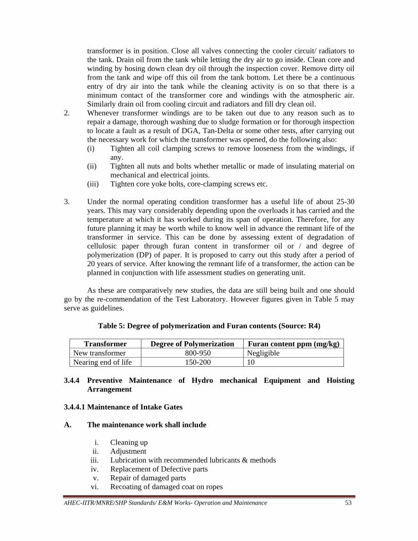
AHEC-IITR/MNRE/SHP Standards/ E&M Works- Operation and Maintenance 53
transformer is in position. Close all valves connecting the cooler circuit/ radiators to the tank. Drain oil from the tank while letting the dry air to go inside. Clean core and winding by hosing down clean dry oil through the inspection cover. Remove dirty oil from the tank and wipe off this oil from the tank bottom. Let there be a continuous entry of dry air into the tank while the cleaning activity is on so that there is a minimum contact of the transformer core and windings with the atmospheric air. Similarly drain oil from cooling circuit and radiators and fill dry clean oil.
2. Whenever transformer windings are to be taken out due to any reason such as to repair a damage, thorough washing due to sludge formation or for thorough inspection to locate a fault as a result of DGA, Tan-Delta or some other tests, after carrying out the necessary work for which the transformer was opened, do the following also: (i) Tighten all coil clamping screws to remove looseness from the windings, if
any. (ii) Tighten all nuts and bolts whether metallic or made of insulating material on
mechanical and electrical joints. (iii) Tighten core yoke bolts, core-clamping screws etc.
3. Under the normal operating condition transformer has a useful life of about 25-30
years. This may vary considerably depending upon the overloads it has carried and the temperature at which it has worked during its span of operation. Therefore, for any future planning it may be worth while to know well in advance the remnant life of the transformer in service. This can be done by assessing extent of degradation of cellulosic paper through furan content in transformer oil or / and degree of polymerization (DP) of paper. It is proposed to carry out this study after a period of 20 years of service. After knowing the remnant life of a transformer, the action can be planned in conjunction with life assessment studies on generating unit.
As these are comparatively new studies, the data are still being built and one should
go by the re-commendation of the Test Laboratory. However figures given in Table 5 may serve as guidelines.
Table 5: Degree of polymerization and Furan contents (Source: R4)
Transformer Degree of Polymerization Furan content ppm (mg/kg) New transformer 800-950 Negligible Nearing end of life 150-200 10
3.4.4 Preventive Maintenance of Hydro mechanical Equipment and Hoisting
Arrangement 3.4.4.1 Maintenance of Intake Gates A. The maintenance work shall include
i. Cleaning up ii. Adjustment
iii. Lubrication with recommended lubricants & methods iv. Replacement of Defective parts v. Repair of damaged parts
vi. Recoating of damaged coat on ropes
AHEC-IITR/MNRE/SHP Standards/ E&M Works- Operation and Maintenance 54
vii. Recording details of all work carried out with date & time. viii. Painting of gates and hoisting arrangement
B. Inspection and checks (a) Daily inspection should be carried out by gate operator to ensure:
i. Proper oiling and greasing wherever required ii. Tightening of loosened parts tightening contacts in electrical system
iii. Checking of ropes and hoisting arrangement. iv. Checking general condition of gates and gate grooves wheels etc.
(b) Periodic inspection (half yearly or annual)
i. Dismantle and check all components for any damage. ii. Rectify damages or replace worn out irreparable components.
iii. All safety precautions must be taken e.g. taking proper shut down, installing safety tags, red flags etc, when any work is being done on gates.
iv. Before taking up work on gates, stop log gates (duly inspected and repaired) must be lowered in the groove meant for the same and plug all leakages through these, if provided.
(c) Lubrication of gate parts : i. Servogem EPI (IOC) or (equivalent of other brand)
a) Rope drum shaft for all hoisting unit (once a month) b) Plumber blocks for all hoisting units fitted with bush bearing (once in
two months) c) Coupling for transmission shaft (once in two months) d) Plumber blocks for manual operation (once in three months)
ii. Servogem – 3 (IOC) or equivalent of other brand Spherical roller bearings for gate wheels (once in 2 months)
iii. Compound – D (Bharat camax) or equivalent of other brand Lifting ropes (once in six months) iv. Servocoat 120 T (IOC) or (equivalent of other brand)
a) Gears & Pinions for all hoisting units (once in 2 months) (Meshing faces only)
b) Gears & Pinions for manual operation (once in 3 months) c) Gears & Pinions for all travel mechanism (once in 2 months) d) Gears & Pinions for position indicators (once in two months)
v. Servosystem (320 IOC) or equivalent of other brand WOM reducer for all hoisting units (once in two months)
C. General Problems in Electrical Circuit and Checks
i. No supply at control panel in spite of turning on main switch – check fuses. ii. Incoming supply healthy but volt meter not showing – check fuses of voltmeter
circuit iii. Motor is running even after pressing stop push button
a. Immediately put-off main switch. b. Check contacts of motor control contactor & push button contacts, if damaged
replace these. c. Reset O/L relay before starting again
AHEC-IITR/MNRE/SHP Standards/ E&M Works- Operation and Maintenance 55
iv. O/L relay tripped a. Check control fuse b. If fuse OK, check control transformer
v. Gate is creeping down & restoration has failed indicating lamp is glowing but alarm not ringing
Check position of toggle switch (it should be in reset position) vi. Indication lamps are not glowing.
Check by pressing lamp test push button replace bulbs, if found fused. 3.4.4.2 Maintenance of main inlet valves The turbine may have either a butterfly or spherical valve. This valve is used each time the unit is shut down. Valve seats, seals, operating links, bearings, bushings, power source and hydraulic links are the main primary maintenance concern.
The valve function should be verified periodically through test or normal frequent
operation.
A. Butterfly Valves
(i) Butterfly valves generally consists of a disc or lattice mounted on a shaft that rotates in cylindrical body
(ii) Usually, the disc and lattice profile is contoured in the flow direction to provide a smooth hydraulic flow and balance forces on the valve.
(iii) The disc is oriented parallel to the flow to minimize any restriction when opened and at right angle to the flow to provide full closure
(iv) Valve seals are on the circumference or in contact portion of the valve body (v) These seals can be replaced or adjusted without removing the disc from the valve.
(vi) Valves have flanged connections and spool pieces to facilitate dismantling. Sometime welded connection are preferred to save cost
B. Maintenance Procedure
(i) Check operating system daily and ensure it is working smoothly (ii) Check for any leakage through joints daily
(iii) Replace main seals in annual maintenance, if damaged (iv) Other seals may be replaced as and when heavy leakage is observed (v) Overhaul operating system annually
(vi) Replace gaskets in flanged connection during annual overhaul C. Spherical Valves Spherical valves have a body shaped like hollow sphere with flanges or other connection for mounting in a piping system. The rotor, shaped like ball, has a cylindrical hole through its centre at right angles to support shafts located on each side of valve. In open position with rotor opening parallel to the flow direction, the valve offers an unrestricted flow with minimum disturbance to the flow path. To close the valve, the valve rotor is turned to 90o from the axis of rotor opening.

AHEC-IITR/MNRE/SHP Standards/ E&M Works- Operation and Maintenance 56
Spherical valve has tendency to close for positions less than 50% opening which facilitates emergency closing. Moveable seals reduce valve leakage when the valve is closed. Mostly valves have both upstream and downstream seal. The upstream seal is maintenance seal or emergency seal, the downstream seal is working seal. When valve is closed under full pressure, the upstream maintenance seal allows replacement or maintenance of the working seal without dewatering the penstock. The upstream maintenance seals have positive mechanical locking to prevent accidental opening.
Daily checks of operating system and remedial measure are must.
(i) Annual inspection and overhauling of mechanical seal after dewatering penstock is must.
(ii) Annual inspection and over hauling of operating seal is also essential. (iii) Annual overhauling of operating mechanism to ensure smooth working throughout
year is also done. (iv) Annual overhauling of the valve rotor and other parts are also taken up as required. D. Following Checks are also essential during annual maintenance
i. Checking and attending leakages from Valve & dismantling joint. ii. Checking and attending oil leakages from Servomotor
iii. Checking the operation of operating valves. iv. Checking and attending the setting of Limit Switches & Operation of the same v. Checking and attending leakages of distributing valve
vi. Checking the correct working of the pressure gauges. Lubricate the parts if necessary.
vii. Checking and attending for leakages in the piping. viii. Checking all the MIV System connections & Union for tightness
ix. Checking all the MIV servo linkage during operation, look for backlash x. Cleaning of valve body, seal & solenoid valve
xi. Checking the actuating solenoids for operation of valve. Cleaning the contacts and rollers.
xii. Checking the operation of bypass valve xiii. Checking for cracks, pitting and cavitation etc. of MIV and Servomotor xiv. Inspection of Rubber Seals xv. Checking trunions & bushes, bolts & nuts etc.
xvi. Checking gland packing and lubrication xvii. Checking foundation bolts and nuts of valves & servomotor. Cleaning the bolts
and nuts etc. xviii. Checking servomotor piston and its collars & its gland packing
xix. Checking hole of the servomotor cylinder xx. Checking the pins and bushes of servomotor & its air valve
xxi. Checking the opening & closing times of the MIV.
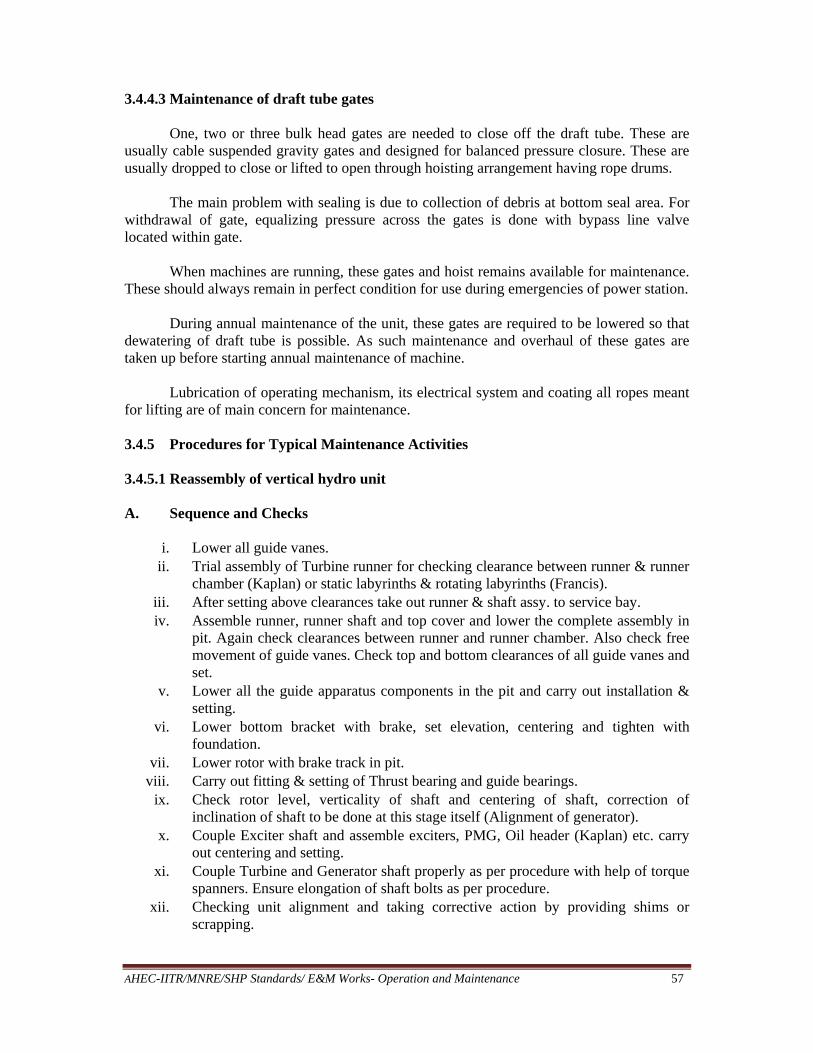
AHEC-IITR/MNRE/SHP Standards/ E&M Works- Operation and Maintenance 57
3.4.4.3 Maintenance of draft tube gates
One, two or three bulk head gates are needed to close off the draft tube. These are usually cable suspended gravity gates and designed for balanced pressure closure. These are usually dropped to close or lifted to open through hoisting arrangement having rope drums. The main problem with sealing is due to collection of debris at bottom seal area. For withdrawal of gate, equalizing pressure across the gates is done with bypass line valve located within gate. When machines are running, these gates and hoist remains available for maintenance. These should always remain in perfect condition for use during emergencies of power station. During annual maintenance of the unit, these gates are required to be lowered so that dewatering of draft tube is possible. As such maintenance and overhaul of these gates are taken up before starting annual maintenance of machine. Lubrication of operating mechanism, its electrical system and coating all ropes meant for lifting are of main concern for maintenance. 3.4.5 Procedures for Typical Maintenance Activities 3.4.5.1 Reassembly of vertical hydro unit A. Sequence and Checks
i. Lower all guide vanes. ii. Trial assembly of Turbine runner for checking clearance between runner & runner
chamber (Kaplan) or static labyrinths & rotating labyrinths (Francis). iii. After setting above clearances take out runner & shaft assy. to service bay. iv. Assemble runner, runner shaft and top cover and lower the complete assembly in
pit. Again check clearances between runner and runner chamber. Also check free movement of guide vanes. Check top and bottom clearances of all guide vanes and set.
v. Lower all the guide apparatus components in the pit and carry out installation & setting.
vi. Lower bottom bracket with brake, set elevation, centering and tighten with foundation.
vii. Lower rotor with brake track in pit. viii. Carry out fitting & setting of Thrust bearing and guide bearings.
ix. Check rotor level, verticality of shaft and centering of shaft, correction of inclination of shaft to be done at this stage itself (Alignment of generator).
x. Couple Exciter shaft and assemble exciters, PMG, Oil header (Kaplan) etc. carry out centering and setting.
xi. Couple Turbine and Generator shaft properly as per procedure with help of torque spanners. Ensure elongation of shaft bolts as per procedure.
xii. Checking unit alignment and taking corrective action by providing shims or scrapping.

AHEC-IITR/MNRE/SHP Standards/ E&M Works- Operation and Maintenance 58
xiii. Carry out load sharing of thrust pads. xiv. After completing assembly of machine and rotating the machine at no load check
balancing of rotor as per procedure. Balancing of the machine by adding calculated weight on rotor spider and at proper angle is done.
xv. Check vibrations of machine at no load, part load and full load, rectify defects, if any.
3.4.5.2 Checking Concentricity of Labyrinth Seals in Francis turbines
The upper and lower labyrinth rings must be concentric with the shaft to within 10% of the gap on one side of the labyrinth seals. This is checked with a special device mounted on the shaft (Fig. 7).
Fig 7: Checking Labyrinth Concentration (Source R4)
3.4.5.3 Balancing of Runner
(i) For balancing of runner a device as shown in Fig 8. will be required. (ii) The top of stand will have half portion of sphere having hardened surface will be
fixed so as to create pivot point. (iii) At the lower end of upper cylinder of runner bore an arrangement to fix hardened
steel plate, its centre should match with the centre of runner. It has to rest on the centre point of half sphere mounted on balancing device.

AHEC-IITR/MNRE/SHP Standards/ E&M Works- Operation and Maintenance 59
Fig 8: Balancing of Runner (Source R4)
(a) Runner is placed on the device in such a manner that it should swing freely (b) Steps of balancing
i. Place runner on the device – check free swing of runner. ii. The runner will be up on lighter side and will have maximum height at one
point from the base plate over which balancing device is placed perfectly in vertical position.
iii. The centre of gravity of runner should be well below the centre of gravity sphere (out of which half sphere is imagined to be carved out).
iv. The weight is to be placed on the bottom cylinder at such a place on lighter side that runner comes to the equilibrium position.
v. For checking horizontality a precision level is placed at six places on the top surface of upper cylinder. For achieving this position the weight may have to be moved either to left or to right to have correct magnitude of weight and as well as its position.
vi. This process is repeated by placing weights at six to eight positions on the circumference of the runner. The magnitude of imbalance is half of the maximum and minimum weight needed for this. The weight of this imbalance is placed where the maximum weight was placed.
3.4.5.4 Checking concentricity of Kaplan runner
(a) Concentricity of Kaplan runner is checked in service bay after assembly of runner blades and their operating mechanism but before hydraulic testing.
(b) For this a special device, schematic of which is shown in Fig 9 will be required. This device can be mounted on the shaft after checking horizontality of the top of runner hub and verticality of the shaft.
(c) As shown in the figure a rotating boom having jerk free motion will have a piano wire with dash pot.
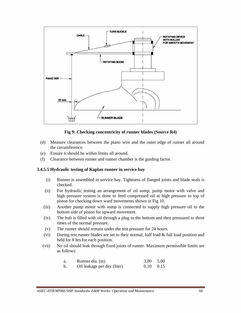
AHEC-IITR/MNRE/SHP Standards/ E&M Works- Operation and Maintenance 60
Fig 9: Checking concentricity of runner blades (Source R4)
(d) Measure clearances between the piano wire and the outer edge of runner all around the circumference.
(e) Ensure it should be within limits all around. (f) Clearance between runner and runner chamber is the guiding factor.
3.4.5.5 Hydraulic testing of Kaplan runner in service bay
(i) Runner is assembled in service bay. Tightness of flanged joints and blade seals is
checked. (ii) For hydraulic testing an arrangement of oil sump, pump motor with valve and
high pressure system is done to feed compressed oil at high pressure to top of piston for checking down ward movements shown in Fig 10.
(iii) Another pump motor with sump is connected to supply high pressure oil to the bottom side of piston for upward movement.
(iv) The hub is filled with oil through a plug in the bottom and then pressured to three times of the normal pressure.
(v) The runner should remain under the test pressure for 24 hours. (vi) During test runner blades are set to their normal, half load & full load position and
held for 8 hrs for each position. (vii) No oil should leak through fixed joints of runner. Maximum permissible limits are
as follows: a. Runner dia. (m) 3.00 5.00 b. Oil leakage per day (liter) 0.10 0.15

AHEC-IITR/MNRE/SHP Standards/ E&M Works- Operation and Maintenance 61
Fig 10: Arrangement for Hydraulic Testing of Kaplan Runner in Service Bay (Source R4)
3.4.5.6 Centering and alignment of vertical hydro generator
(i) Alignment of rotor during installation ensures that rubbing surface of thrust bearings and the shaft mirror disc face are perpendicular to rotor shaft axis.
(ii) The procedure for rotor centering is as follows. a. First centering of turbine runner and shaft is carried out with respect to
stationery labyrinths or runner chamber b. The generator is then provisionally centered relative to turbine shaft. c. Then perpendicularity of rubbing surfaces of thrust bearing and shaft flange face
to the generator shaft centre line is checked. d. Then final alignment of generator and turbine is done.
I. Procedure for alignment of unit
i. Set elevation of thrust bearing
ii. Lock the guide bearing near to the thrust bearing iii. Carry out rotational check of gen. shaft iv. Calculate maximum throw and direction v. Minimize throw by scrapping insulated surface of mirror disc.
vi. Couple generator shaft with turbine shaft vii. Again check elevation & level of thrust bearing
viii. Carry out rotational checks ix. Find out run out at LGB & coupling flange x. If throw is still more again carry out scrapping of insulated surface of mirror
discs. Again check by rotation method and repeat till throw is within limit xi. Check throw and its direction at TGB
xii. Minimize throw by providing shim between coupling flange

AHEC-IITR/MNRE/SHP Standards/ E&M Works- Operation and Maintenance 62
xiii. Check throw at LGB, coupling flange and TGB, ensure these are within limit. This is necessary to establish unit axis.
xiv. Check verticality of shaft with respect to duly leveled thrust bearing at correct elevation.
II. Coupling of Shafts A. Before coupling of generator shaft and turbine it is to be checked that requirements
shown in Table 6 are met:
Table 6: Allowable Deviation in Shaft Coupling
S. No. Type of Deviation Allowable Deviation in mm 1. Shift of Gen. shaft axis with turbine shaft
axis 0.01 mm
2. Non parallelity of mating surfaces of both flanges at shaft dia. Up to 600 mm Up to 1000 mm Up to 1500 mm
0.020 0.025 0.030
B. Coupling
i. Force of tightening of all bolts should be identical ii. Elongation of bolts, required to ensure proper tightening
iii. Soundness of flange connection is checked by filler gauge of 0.03 mm thickness III. Setting Elevation of Thrust Bearing
(i) Elevation of upper/ lower bracket should be such that the runner is at desired level (ii) Allowance for deflection of support bracket due to weight of rotating parts and initial
thrust should be taken into account. (iii) Mount thrust bearing on support bracket (iv) Check perpendicularity of thrust collar with shaft (v) Set elevation of bearing, by providing shims under flexible support
IV. Rotational Checks
(i) Arrangement to turn rotor by 360o in steps of 45o smoothly (ii) In machines having high pressure lubrication of TH.B. It is possible to rotate machine
manually. (iii) In other machine mechanical arrangement is made and rotation is done with the help
of EOT crane. For lubrication of thrust pads in such case is ensured by using Molybdenum-di-Sulfide Grease (Molysulf Grease)
(iv) Mount dial Gauges at UGB, LGB, Flange & TGB to find out run out (Fig 11) (v) Throw and its direction is calculated by resultant method (Table 7 & Fig 12)
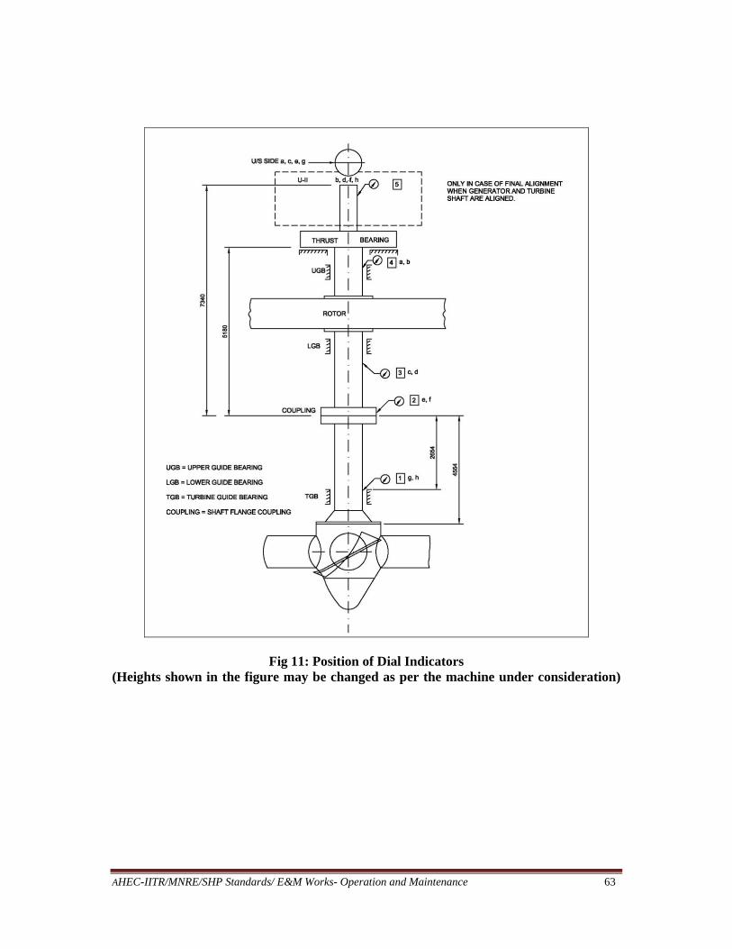
AHEC-IITR/MNRE/SHP Standards/ E&M Works- Operation and Maintenance 63
Fig 11: Position of Dial Indicators (Heights shown in the figure may be changed as per the machine under consideration)

AHEC-IITR/MNRE/SHP Standards/ E&M Works- Operation and Maintenance 64
Table 7: Resultant Method of Alignment (Actual Example of Unit-I of a Power Station)
(Vectorial Resultant – at Fig. 6)
Angular Position of shaft/
Dial Gauge
Upstream Side Dial Gauge Erection bay Side Dial Gauge No. of Point
at Shaft
UGB a
LGB c
Flangee
TGB g
c-a
c-a
g-a
UGB b
LGB d
Flangef
TGBh
d-b
f-b
h-b
No. of Point
at Shaft
00 0 0 0 0 0 0 0 0 0 0 0 0 0 0 0 2 450 1 + ½
Dia
l Gau
ge w
as n
ot
fixe
d
– 32 – 46
Dia
l Gau
ge w
as n
ot
fixe
d
– 31.5 – 45.5 0
Dia
l Gau
ge w
as n
ot
fixe
d
+ 1 + 1
Dia
l Gau
ge w
as n
ot
fixe
d
+ 1 + 1 3 900 2 0 – 40 – 85 – 40 – 85 + 3½ + 3 + 30 – ½ + 26½ 4 1350 3 0 – 40 – 86 – 40 – 86 + 6½ + 13 + 31 + 6½ + 24½ 5 1800 4 0 – 30 – 65 – 30 – 65 + 7 + 28 + 71 + 21 + 64 6 2250 5 + 1 – 8 – 22 – 9 – 23 + 7 + 41 + 80 + 34 + 73 7 2700 6 – ½ + 15 + 26 + 15½ + 26½ + 7 + 30 + 76 + 23 + 69 8/0 3150 7 0 + 6 + 17 + 6 + 17 + 3 + 18 + 51 + 15 + 48 1 3600 8/0 – 1 + 4 + 14 + 5 + 15 + 1 – 6 – 1 – 7 – 2 2
Note: (a) The readings of upstream side dial gauges are not acceptable as closing error is more.
(b) E.B. side readings are fine because (i) closing error is negligible (ii) curve plotted along X-Y axis is nearer to sine curve (iii) these are confirmed in subsequent rotation also. Further calculations and correction is based on these.

AHEC/MNRE/SHP Standards/ E&M Works- Operation and Maintenance 65
Fig 12: Resultant Method of Throw Calculation
V. Shimming or Scrapping Amount of Scrapping or Shim Thickness (Fig 13 & 14)
lengtheffective2diameterαthrowresultantMax.t''
a. For correcting gen. shaft
(i) t = amount of scrapping/shimming (ii) Max. throw at coupling flange for correcting gen. shaft (iii) Eff. Length = distance between insulated surface or mirror disc and coupling
flange (iv) Diameter = Dia of thrust bearing mirror disc.
b. For correcting turbine shaft
(i) Max throw at TGB (ii) Eff. Length = Between Flange and TGB (Dial Gauge Locations) (iii) Diameter = Dia. of coupling flange
Shimming or scrapping to be done at coupling shaft joint. Shimming shall be in the
direction of throw while scrapping will be in opposite direction.
Exact replica on some hard sheet is prepared with marking of bolt hole location. Shim cutting is done carefully avoiding holes. There should be adequate gap between two shims so that they are not over lapped. Rounding of sharp edges is to be ensured.
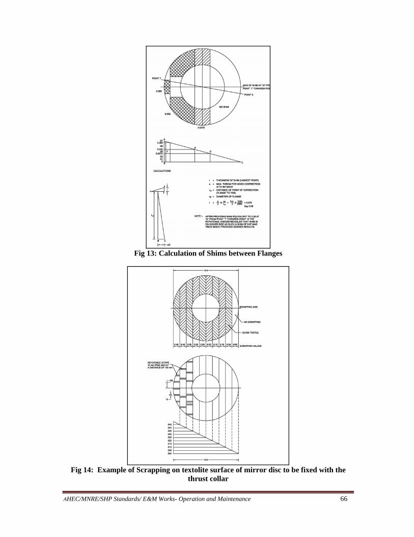
AHEC/MNRE/SHP Standards/ E&M Works- Operation and Maintenance 66
Fig 13: Calculation of Shims between Flanges
Fig 14: Example of Scrapping on textolite surface of mirror disc to be fixed with the
thrust collar

AHEC/MNRE/SHP Standards/ E&M Works- Operation and Maintenance 67
VI. Checking Verticality of Shaft (Fig 9)
Four piano wires with dash posts are placed as shown in the Fig 15. Precision stick micrometer is used to measure a1, b1, c1, d1 and a2, b2, c2, d2. The whole procedure of calculation of deviation is given with the figure it self. If the deviation is less than 0.01 mm/ m of shaft length, them verticality is taken to be normal otherwise corrective measure has to be taken.
Fig 15: Checking Verticality of Generator Shaft
3.4.5.7 Load sharing of the thrust bearing
There must be uniform distribution of load between all thrust pads. Over loading of any pad may cause destruction of babbit material and failure of thrust bearing. The load is equalized after the generator shaft wobble has been eliminated or after the turbine and generator shaft has been connected and the unit has been aligned.
Uniform distribution of load is achieved by tightening supporting screws against the elastic plates beneath the shoes carrying rotor weight. This is done by striking the spanner with sledge hammer.

AHEC/MNRE/SHP Standards/ E&M Works- Operation and Maintenance 68
The load distribution is adjusted in this manner by first checking that all supporting screws are tightened equally. The position of locking device of each support screw is then marked with the vertical lines on it and on the thrust bearing housing or on the support stand. A sledge hammer of approximately 8 kg weight is then used to strike hard once or twice at the end of 600 to 700 mm long spanner placed on the head of supporting screw considered. The process is carried out on all shoes with the same force. The position of all pads are measured after each round with a slide caliper and distances between the lines on the locking devices and on thrust bearing housing are recorded. This tightening process is repeated several times until distances between the lines are increased equally by hammer blows on all supporting screws. Another round of tightening the screws is then performed with lighter sledge hammer. Adjustment is considered completed if the distance between the lines has not changed in one round. The load can be adjusted by using a dial indicator also as shown in Fig 16.
Fig 16 : Arrangement for Load Sharing (Source R4)
The support screws must be locked after completion of this activity.
3.4.5.8 Dynamic balancing of low speed hydro generator
i. A sensitive dial gauge (0.01 mm) is fixed as shown in Fig 17. ii. A suitable bracket, which is firm and rigid, will be required to fix dial gauge.
iii. Four runs of machine at full speed will be required to find out magnitude of weight to be fixed and position of correction
(a) First run
Run to rated speed and note total deflection of the pointer on dial (the reading is proportional to the unbalance force). Make two marks on rotor ‘A’ & ‘B’ at Oo and 180o respectively
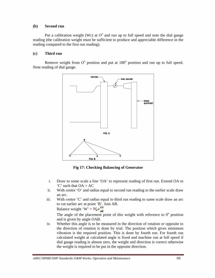
AHEC/MNRE/SHP Standards/ E&M Works- Operation and Maintenance 69
(b) Second run
Put a calibration weight (Wc) at Oo and run up to full speed and note the dial gauge reading (the calibration weight must be sufficient to produce and appreciable difference in the reading compared to the first run reading).
(c) Third run
Remove weight from Oo position and put at 180o position and run up to full speed. Note reading of dial gauge.
Fig 17: Checking Balancing of Generator
i. Draw to some scale a line ‘OA’ to represent reading of first run. Extend OA to ‘C’ such that OA = AC
ii. With centre ‘O’ and radius equal to second run reading to the earlier scale draw an arc.
iii. With centre ‘C’ and radius equal to third run reading to same scale draw an arc to cut earlier arc at point ‘B’. Join AB. Balance weight ‘W’ =
The angle of the placement point of this weight with reference to 0o position and is given by angle OAB.
iv. Whether this angle is to be measured in the direction of rotation or opposite to the direction of rotation is done by trial. The position which gives minimum vibration is the required position. This is done by fourth run. For fourth run calculated weight at calculated angle is fixed and machine run at full speed if dial gauge reading is almost zero, the weight and direction is correct otherwise the weight is required to be put in the opposite direction.
AHEC/MNRE/SHP Standards/ E&M Works- Operation and Maintenance 70
Note: Above method is now obsolete but useful when present day electronic meters are not available and balancing is to be checked at site.
3.4.5.9 Alignment horizontal generating set Adjustment of Turbine Shaft
i. The centre line of turbine bearing with respect to longitudinal axis of generator is checked by stretching a horizontal wire through spiral casing and along bearing centre line. Correct position of wire inside spiral casing is checked with inside micrometer.
ii. Bearing housings are centered with respect to longitudinal axis of generator by an end gauge which is inserted into the bores of bearing shell
iii. Ensure clearances of guide vanes at both ends are uniform and are as per drawing. Filler gauge is used to check these. These can be adjusted by tightening bolts. When distributor is closed there should be no clearance in guide vanes.
iv. Measure clearance with filler gauge between shaft and the lower guide bearing shell to ensure correct position of rotating parts of turbine.
v. If there is no clearance, it indicates that the shaft is resting on both bearings. vi. The horizontal position of shaft is checked by placing a level successively on both
bearing journals. Then turn the level by 180o and place in the same position as before and check level. Arithmetic mean of two measurements should be taken, the two should not differ more than one division. If difference is more investigate reasons and take remedial measure.
vii. The permissible inclination in shaft should be as per drawing in mm per m length of shaft.
viii. The permissible inclination in transverse direction should be as per drawing in mm / m of shaft length. This should also be checked with level.
ix. The radial clearance between runner and the cover plates should be as per drawing and should be uniform.
x. The gaps between stationary and rotating labyrinths are as per drawing. xi. The axial gaps in labyrinth seals should also be measured and these should be as
per drawing . These are measured by pushing the rotating parts to extreme positions.
xii. All the clearances and gaps are measured again after turning the rotating parts through 180o and 360o. These should be within permissible limit.
xiii. 1 mm thick lead wire of suitable length is used to measure clearance between turbine shaft and the upper bearing shell. Length of this wire is placed across the shaft in two sections beneath the shell which is then tightened well. The thicknesses of flattened wire thus indicate the clearance on top of the shaft which should be 0.2% of shaft dia.
xiv. The lateral clearance between the shaft and the lower shell are checked at a depth 10 to 12 mm below the plane in which bearing is split. These should be half of clearance between shaft and upper bearing shell.
xv. The adjusted shaft of turbine will be reference base for alignment of generator shaft.
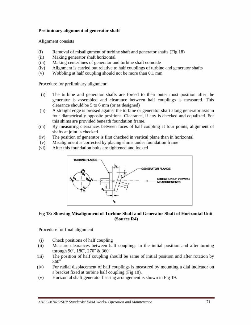
AHEC/MNRE/SHP Standards/ E&M Works- Operation and Maintenance 71
Preliminary alignment of generator shaft Alignment consists
(i) Removal of misalignment of turbine shaft and generator shafts (Fig 18) (ii) Making generator shaft horizontal (iii) Making centerlines of generator and turbine shaft coincide (iv) Alignment is carried out relative to half couplings of turbine and generator shafts (v) Wobbling at half coupling should not be more than 0.1 mm
Procedure for preliminary alignment:
(i) The turbine and generator shafts are forced to their outer most position after the
generator is assembled and clearance between half couplings is measured. This clearance should be 5 to 6 mm (or as designed)
(ii) A straight edge is pressed against the turbine or generator shaft along generator axis in four diametrically opposite positions. Clearance, if any is checked and equalized. For this shims are provided beneath foundation frame.
(iii) By measuring clearances between faces of half coupling at four points, alignment of shafts at joint is checked.
(iv) The position of generator is first checked in vertical plane than in horizontal (v) Misalignment is corrected by placing shims under foundation frame
(vi) After this foundation bolts are tightened and locked
Fig 18: Showing Misalignment of Turbine Shaft and Generator Shaft of Horizontal Unit (Source R4)
Procedure for final alignment (i) Check positions of half coupling
(ii) Measure clearances between half couplings in the initial position and after turning through 90o, 180o, 270o & 360o
(iii) The position of half coupling should be same of initial position and after rotation by 360o
(iv) For radial displacement of half couplings is measured by mounting a dial indicator on a bracket fixed at turbine half coupling (Fig 18).
(v) Horizontal shaft generator bearing arrangement is shown in Fig 19.
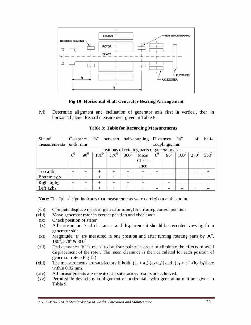
AHEC/MNRE/SHP Standards/ E&M Works- Operation and Maintenance 72
Fig 19: Horizontal Shaft Generator Bearing Arrangement
(vi) Determine alignment and inclination of generator axis first in vertical, then in horizontal plane. Record measurement given in Table 8.
Table 8: Table for Recording Measurements
Site of measurements
Clearance “b” between half-coupling ends, mm
Distances “a” of half-couplings, mm
Positions of rotating parts of generating set 00 900 1800 2700 3600 Mean
Clear-ance
00 900 1800 2700 3600
Top a1;b1 + + + + + + + – – – + Bottom a3;b3 + + + + + + – – + – – Right a2;b2 + + + + + + – + – – – Left a4;b4 + + + + + + – – – + – Note: The “plus” sign indicates that measurements were carried out at this point. (vii) Compute displacements of generator rotor, for ensuring correct position
(viii) Move generator rotor in correct position and check axis. (ix) Check position of stator (x) All measurements of clearances and displacement should be recorded viewing from
generator side. (xi) Magnitude ‘a’ are measured in one position and after turning rotating parts by 90o,
180o, 270o & 360o (xii) End clearance ‘b’ is measured at four points in order to eliminate the effects of axial
displacement of the rotor. The mean clearance is then calculated for each position of generator rotor (Fig 18)
(xiii) The measurements are satisfactory if both [(a1 + a3)-(a2+a4)] and [(b1 + b3)-(b2+b4)] are within 0.02 mm.
(xiv) All measurements are repeated till satisfactory results are achieved. (xv) Permissible deviations in alignment of horizontal hydro generating unit are given in
Table 9.

AHEC/MNRE/SHP Standards/ E&M Works- Operation and Maintenance 73
Table 9: Permissible Deviations in Alignment of Horizontal Hydro Generating Unit
Rotational speed of generating set, rpm
Permissible skew ness and eccentricity, mm
Up to 500 0.15 Up to 750 0.10 Up to 1500 0.08
(xvi) If, after alignment radial and end clearances at diametrically opposite points are within
limit as shown in table, the alignment is taken as adequate otherwise repeat alignment procedure and compute more accurately.
(xvii) Computing eccentricity of generator shaft with respect to turbine shaft (measurement ‘a’) and its direction and computing inclination and its direction (measurement ‘b’) is done as explained below: (Fig 20) Displacement of generator shaft axis due to eccentricity relative to turbine shaft:
Horizontal plane hx = (a2-a4) / 2 Vertical plane hy = (a1-a3) / 2
Fig 20: Displacements of Generator Bearings (Source R4)
(xviii) The displacement of bearings due to inclination of shaft is given by difference between end clearances. They depend on the location of bearings and dia. of coupling ‘Dc’. (a) Front bearing in horizontal plane
kx1 = (b2-b4) l1/Dc kx2 = (b2-b4) l2/Dc

AHEC/MNRE/SHP Standards/ E&M Works- Operation and Maintenance 74
(b) Front bearing in vertical plane Ky1 = (b1-b3) l1/Dc ky2 = (b1-b3) l2/Dc
Correct position of the generator rotor can be obtained by moving its bearings by
following distances: (a) Front bearing – horizontal plane
Ax1 = (a2-a4) / 2 + (b2-b4) l1/ Dc Ax2 = (a2-a4) / 2 + (b2-b4) l1/ Dc
(b) Front bearing – vertical plane Ay1 = (a1-a3) / 2 + (b1-b3) l1/ Dc At2 = (a1-a3) / 2 + (b1-b3) l2/ Dc
(xix) The rotor must be moved up and to the right if the computed displacement is positive (xx) The rotor must be moved down and to left if the computed displacement is negative
(xxi) The air gaps of generator are checked after completing alignment. These should be equal all around the circumference
(xxii) The turbine and generator half coupling are connected after completing alignment of generator shaft
4.0 GENERAL GUIDELINES
4.1 Taking Over of Plant for O&M
The O&M of the plant shall be taken over from agency executing the project after due diligence and checking following conditions. A report shall be prepared and both handing over and taking over party shall sign it. Following are the guide lines: 4.1.1 Operating condition of E&M equipment shall be monitored for 72 hrs continuous
running for full load condition and results, observations are noted. If any defect is found, it shall be noted and corrected. This shall include turbine, generator, auxiliaries, control metering and relay panels, HT and LT switchgear, main and auxiliary transformer and switchyard equipments.
4.1.2 All civil building and structures such as water carrier system, lake, diversion weir,
channel, pipe line, fore bay, tailrace, draft tube, etc shall be monitored during load test and observations and defects noted. However all civil structures under water shall be inspected on draining, if possible. Leakages, cracks on wall, and operation of main gates shall be noted.
4.1.3 All the area of the plant shall be cleaned and all rooms checked for unwanted material
stored in it. Such material shall be taken out of building and stored in closed out door yard.
4.1.4 All the spares of the E&M equipment shall be listed and their condition checked for
use during replacement. These shall include gate, valve, turbine, generator transformers, breakers, panels, AVR and governor spares.

AHEC/MNRE/SHP Standards/ E&M Works- Operation and Maintenance 75
4.1.5 All the tools and instruments ordered for the plant shall be listed and their condition checked.
4.1.6 Documents: Following documents shall be insisted upon:
(i) All plant and equipment drawings with as executed status. (ii) All commissioning reports duly signed. This shall include generator, turbine, auxiliaries, transformers and breakers, DC station battery, battery charger (iii) Cable schedule and termination drawing, panel wiring drawing. (iv) Supplier’s manuals including erection and troubleshooting manual. (v) Relay test report and relay setting duly signed by manager/ resident engineer.
4.2 Manpower, Selection and Training 4.2.1 Man power required for the operating and maintenance of SHP shall be based on
following factors:
(i) Type of plant such as ROR, dam based or canal based. The manpower for the ROR plant is more because of the spread of hydraulic structures, the water channel and its equipment.
(ii) The number of shifts/ hours the plant is going to work e.g. one shift or three shift. A plant with 3 shift working will need more staff than a single shift.
(iii) Location of the plant, a remotely located plant will need additional staff for the support services such as transport, maintenance of residences, drinking water supply etc.
This may increase the strength of the remotely located ROR plant. However the
manpower can be kept minimum by employing a multidisciplinary force such as an engineer with experience in civil and electromechanical work or technician with driving experience etc. The guiding factor is safety of equipment and manpower.
Other method is to employ local labor, during requirement of additional work such as rainy season where inspection of water channel is needed or during annual maintenance work. It will benefit the plant, if these persons are given proper on job training. 4.2.2 Selection Man power required for operation and maintenance shall be selected before commercial operation of the plant.
(i) The operation staff shall be selected well in advance preferably during the pre-commissioning and commissioning of the plant. They should be given proper training otherwise possibility of mishandling of plant, loss of generation, unsafe operation etc. cannot be ruled out.
(ii) The experience of the persons shall be in hydro generating plant, DG plant of a co-generation plant. An experience on large electrical substation with DG set may be accepted.

AHEC/MNRE/SHP Standards/ E&M Works- Operation and Maintenance 76
(iii) Plant in charge having basic degree/ diploma in electrical with experience in civil and mechanical works is most suitable.
(iv) Testing engineer is most important for any generating plant. He should be experienced engineer familiar with all equipment testing to take decision in case of any fault on electrical equipment such as generator, transformer and switchgear. This being a specialized job it may be difficult to get such persons and to hold them as such can be engaged by group of plants or among the IPPs in the area.
(v) For the technician an ITI certificate with hands on experience in electro-mechanical work such as DG plant, electrical installation, hydraulic equipment, electrical panel, PLC panels cabling work etc.
(vi) Contractual work such as civil maintenance, welding and fabrication, etc may be awarded on annual basis to keep work force low.
4.2.3 Training of Operation Staff The operation staff shall be given training by Sr. Experienced personal and also on simulator, if available. The training shall be in the area of SHP operation, maintenance, safety and fire fighting. A training period of three month is necessary for small hydropower plant.
(i) On completion of training the trainee shall be assessed for his skills and capability on actual work in the plant where they will be working.
(ii) On placing them on operation duty they shall be periodically assessed for their performance in actual operation such as start of units etc.
4.3 Essential T&P, Instruments Etc (i) Ordinary tools, instruments
For effective maintenance it is necessary to list out all required ordinary T&P as also assess quantity and arrange the same otherwise it may become difficult even for a skilled and capable technicians to carry out the require maintenance job. Ordinary T&P includes different type & sizes of screw drivers, pliers, spanners hammers etc.
(ii) Special T&P
Such type of T&P is required during assembly or dismantling of machines. For example, rotor lifting device and endless slings, pole turning device, shaft lifting device, rotating device and slings for alignment, shaft extension pieces and so on. These are not required for day to day maintenance; as such these should be properly stored and secured. Necessary maintenance, if required, must be carried out on these devices in time. Slings should be stored duly coated with preservatives as recommended by the manufactures.
4.4 Fire Protection and Fire Fighting
It is necessary to install necessary hydrant points, fire extinguishers at different locations of the power station as per recommendations of district fire officer. Periodic drill of use of different types of fire extinguishers is must so that staff on duty in the power plant could operate these in case of emergencies.
AHEC/MNRE/SHP Standards/ E&M Works- Operation and Maintenance 77
First aid boxes as per recommendation of Factory Rules must be kept in the PS and these should be inspected periodically by station in charge. Timely recoupment of consumed items must be ensured by shift in charge. Shift in charge should also ensure timely refilling of fire extinguishers installed in the powerhouse. He must periodically check working of hydrant points. Smoking inside power station should be prohibited. Throwing match sticks and other burning stuff may sometime create fire in the power station. Additional fire extinguishers must be kept during maintenance especially when activities like, welding, brazing etc. are going on.
Asbestos cloth must be used to cover electrical parts during such maintenance
activities. In power stations normally following types of fire extinguishers are used:
(i) Dry chemical type foam type (chemical foam) (ii) CO2 cylinders (iii) Fire hydrants (iv) Sand and water buckets
4.5 Safety Aspect of Running SHP It is said that 90% of accidents are avoidable. Out of these 20% are due to faulty conditions and 20% due to faulty behavior and 60% due to both. Accidents cause human suffering and loss of production to the organization. Safety measures are therefore, essential. Success of safety measures depends on safety mindedness of the management supervisions and workers. Some of the methods to improve safety consciousness are given below:
(i) Prompt investigations, pin pointing cause of accident and remedial measures (ii) Use of personal protective equipment such as helmet, goggles, gloves safety belts etc. (iii) Arousing safety consciousness through the use of posters, films, journal, safety
talks, safety competition etc. 4.5.1 General Safety Precautions in SHP
(i) All voltage level, even low shall be considered dangerous even though the voltage may not be high to cause shock.
(ii) All electrical circuit to be treated live and no work should be carried out without proper shut down and ensuring that it is (a) De-energized (b) Isolated from all sources (c) Effectively connected with ground
AHEC/MNRE/SHP Standards/ E&M Works- Operation and Maintenance 78
4.5.2 Fundamental on Safety
Prevention of accidents requires whole hearted cooperation of all members of organization. A capable, mentally alert employee will avoid accident.
(i) Unsafe acts which may cause accidents are as follows:
(a) Operation of equipment without authority or warning. (b) Operating without proper instructions (c) Making safety device inactive (d) Working nearby dangerous or live electrical equipment which could
conveniently be de-energized (e) Using defective T&P or equipment or its improper use.
(ii) Unsafe conditions which may cause accidents are as follows:
(a) Ungrounded equipment (b) Defective material or equipment (c) Improper illumination (d) Non standard design and construction
Accidents are, therefore, results of unsafe acts or unsafe conditions or combination of
both.
4.5.3 Safety Precautions and Practices in Operating and Maintenance
(i) No unsafe operation will ever be permitted. Feedback regarding unsafe operation/ condition should be taken into consideration with proper spirit and review should be made to avoid accidents.
(ii) Interlocks should not be by-passed unless it is very essential. Written permissions should be obtained from the superintendent/ in charge of the station. Extra precaution should be taken by all the parties during such cases.
(iii) Equipment are designed for certain operating conditions, it should be operated within prescribed operations limits. Overstressing of the equipment should be for minimum possible time with minimum percentage of overloading. This will avoid damage to the equipment.
(iv) Operation and Maintenance staff should be familiar with the station layout and operations limits of different equipment such as breakers, transformers, isolators CTs, PTs, etc. A person should be allowed to operate or take over the equipment only after he has acquired adequate knowledge of the equipment.
(v) Operation should be carried out as per Operations Instructions. This will help in carrying out operations safely and maintaining uniformity. In case of any modifications/ change in the layout operating instructions should be reviewed.
(vi) Booklets/ manufacturer’s instructions for different equipment should be available and should be referred to before taking out equipment for maintenance.
(vii) It is the responsibility of the supervisor to interpret correctly and explain safety rules and regulations to all the persons concerned and ensures that they thoroughly understand the same.
(viii) Breach of safety rules should be suitably dealt with.

AHEC/MNRE/SHP Standards/ E&M Works- Operation and Maintenance 79
(ix) Only authorized persons shall be allowed to carry out operation and maintenance. (x) Supervisor shall guard against the use of defective safety appliances, tools, and
materials. (xi) In case of any emergency, in which quick action is necessary, in order to
safeguard personals or property, only authorized persons will take necessary action. Under no circumstances attempt shall be made to carryout operations which are not safe.
(xii) All persons must use the standard protective equipment intended for the job. (xiii) All protective equipment should be periodically tested. (xiv) Metal ladders should not be used in switchyard. (xv) First Aid and fire fighting
(a) Adequate number of first aid and firefighting equipment shall be maintained. (b) First aid and artificial respiration chart shall be exhibited. Every person
shall be familiar with the same. (c) Every person shall be familiar and should know how to operate
firefighting equipment, so that fire can be extinguished promptly thus minimizing damage.
(d) In the event of the fire on electrical installation, the affected part shall be immediately switched off and isolated from all the sources.
(xvi) Use HRC fuses only with proper capacity. (xvii) While opening isolator confirm that it is not carrying load current. Similarly
isolator should not be closed on load. (xviii) Underrated circuit breakers should not be used to clear the fault. (ixx) No breaker should be operated beyond stipulated operating duty. (xx) While working on the breaker, its operating mechanism should be de-energized
such as discharging spring, releasing air pressure etc. (xxi) Transformer should be discharged and grounded from all sides (windings).
Neutral grounding of the transformer should not be treated as grounding. (xxii) Current transformer secondary should never to be left open circuited. (xxiii) After cutting out capacitor bank, it should be allowed to discharge through
discharge PT for about 10 minutes. The bank should be grounded with hot stick before commencing the work.
(xxiv) ASKAREL compound used in capacitor bank as a dielectric is very toxic and harmful. Hence, should be handled with great care.
(xxv) Apparatus, frame work and other non-current carrying metal parts associated with power system are to be effectively grounded.
(xxvi) Lighting arresters shall be grounded independently. (xxvii) Isolating switches provided for Generators and synchronous condensers and
other rotating machines should never be opened when connected to any voltage source even when the machine is carrying no load.
(xxviii)The areas should be cordoned off indicating location of work on the particular equipment.
(xxix) Use of safety tags must be ensured while allowing shut down for maintenance on some part/ equipment.

AHEC/MNRE/SHP Standards/ E&M Works- Operation and Maintenance 80
4.6 Documentation 4.6.1 Documentation
Documentation of work done is necessity for future references and analysis of data/information as and when required. It is the responsibility of operation staff to register all appropriate information, operating parameters such as temperature, pressure, levels, generation voltage, current, PF, frequency, MVAR, MW, MWH etc. in the log books and registers. Alarms, annunciations, temperatures, fore bay levels/reservoir levels, inflows etc. are also to be recorded. Trippings with relevant details, such as relay operation details are to be recorded with utmost care. Restoration activities after every tripping should be reported with details of preventive action taken or to be taken based on certain conditions. This information should be presented in prescribed format, should be checked on daily basis by Engineer concerned, who will check and authenticate the same for future use. Periodic maintenance registers are to be maintained giving details of maintenance activities for daily, monthly, annual etc. or break down maintenance. Results of test and measurements carried out during maintenance should be tabulated in standard formats and this should include the commissioning and acceptable values are applicable for proper comparison and planning remedial action. The log books and log sheets normally maintained in SHPs are as follows:- (i) Log books and registers a. Control Room Log Book : Hourly readings of all panel meters, transformer
auxiliaries, generator and transformer temperature, and general condition of equipment, ambient temp
b. Turbine floor Log Book : Hourly readings of bearing temperature, aux. in service, OPU pump running, cooling water pressure, compressor air pr, etc. turbine water head/pressure and other quantities as per manufacturer’s instructions.
c. Control room energy : KWH meter, import – export meter. Aux. consumption meter log sheet. meter-8 hourly ie.once in each shift
d. Defect Register : Record of electrical equipment defects noticed during shift
i. electrical : needing attention of maintenance dept. ii. mechanical : Record of mechanical equipment defects noticed
during shift needing attention of maintenance dept. e. Monthly Generation : Keeps monthly total of unit generation, aux.record
register consumption, running hours, shut down hours, outages, forced and emergency outages.

AHEC/MNRE/SHP Standards/ E&M Works- Operation and Maintenance 81
f. Tripping register : Record of all tripping, cause of tripping, relay action, alarm and anuncition etc.
g. Relay setting register : Record of all relay equipment relay setting giving normal condition and during outage of transformer or line, record of all instructions for revision. This is an extremely important register shall be available for reference at all times
h. Daily report : Keeps daily generation, auxiliary consumption, forced (duplicate) outage, generation loss, loss of water, water utilized, important event during the day, tripping and defects attended etc
i. Station water consumption : Keeps records of daily/ monthly water discharge utilized report. Monthly (duplicate) for generation, water loss due to non availability of m/c Deemed generation register Keeps record of loss of generation while machines are available for generation but either the grid or designed/mutually agreed daily discharge is not available
j. Battery room log sheet : DC battery- cell voltage and specific gravity k. Battery charger log sheet : Condition and parameters of Charger l. Operation manual : Manual giving all step by step operation procedure
for start up, synchronization ,loading, normal, special, emergency shut down and procedure to be followed during malfunctions etc. Giving all equipment data and equipment operating parameter. Guidelines for emergency operation, black start procedure, river discharge and other hydraulic data, all mechanical and electrical auxiliaries operating procedure, details of control, metering and protection and drawings, station interlocking drawings
m. Safety manual : Safety procedure for giving outages, and tagging procedure. Use of tools, cranes, compressor, pumps etc. instructions giving use of fire protections and fighting equipment. First Aid instructions.
n. Disaster management : Gives details of instructions to be followed by shift staff instruction during any disaster. It further gives details of how to act and tackle the disaster.
o. Register of fire & : Keeps record of quarterly/ half yearly drill. Record safety drill of filling of fire extinguishers etc.
Some sample formats of log book and reports are shown from Table 10 to19 (Adapted: from R5) as a guide to create formats for newly commissioned the small hydro power station power stations.

AHEC/MNRE/SHP Standards/ E&M Works- Operation and Maintenance 82
Table 10: Format for Daily Log Sheet
Name of PH Daily Log Sheet Date: Unit – I Unit – II Transformer Grid
Voltage
Current
Load
PF
Freq.
Excitation
G.V
. Op
enin
gs
Dis
char
ge
OP
U P
ress
ure
Pen
stoc
k P
ress
ure
Voltage
Current
Load
PF
Freq.
Excitation
G.V
. Op
enin
gs
Dis
char
ge
OP
U P
ress
ure
Pen
stoc
k P
ress
ure
HV Side
LV Side
RY
Y
B
BR
R
Y
B
MW
M
VR
V
I
RY
YB
BR
R
Y
B
MW
MV
R
V I
V I V I V
Fre
q.
1.00 2.00 3.00 4.00 5.00 - - - - - 24.00
OPERATION/PARAMETER Normal (value) Max. Temp. 0c at Hrs 0c Hrs 00c Hrs 0c Hrs 0c Stator winding Thrust bearing Turbine G.B U.G.B. L.G.B. Any abnormal Operation parameter

AHEC/MNRE/SHP Standards/ E&M Works- Operation and Maintenance 83
Table 11 : Format for Daily Generation, Export/Import of Energy
Daily Generation, Export/ Import Report Name of SHP……………………. Date :
Generation in MU
Daily Auxiliary consumption. MU
Net generation
in MU
Cumulativemonthly
Yearly
Export in MU
Import in MU
Net Export in MU
Deemed Gen. in
MU Pre
reading Present reading
MU
Unit – I
Unit - II
Total
Table 12 : Format for Daily Tripping Daily Tripping Report Name of SHP……….. Date : S. No. Unit/ Line Time Hr. Min Details of Tripping Relay Operated with Alarms and
Flags Remarks
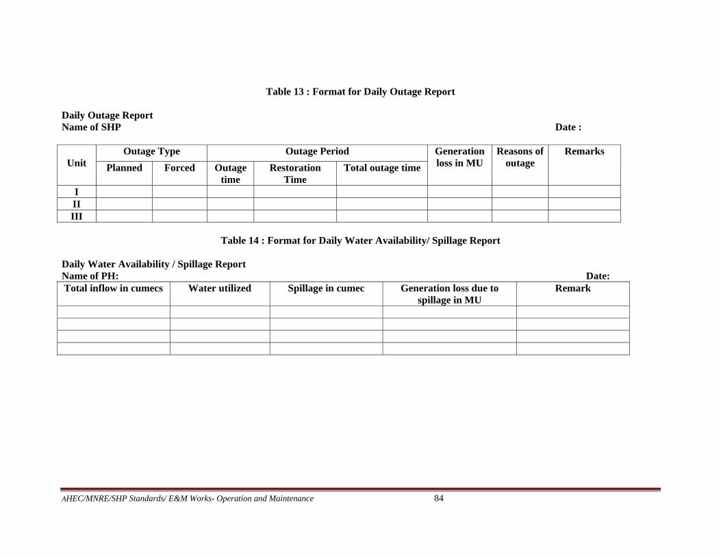
AHEC/MNRE/SHP Standards/ E&M Works- Operation and Maintenance 84
Table 13 : Format for Daily Outage Report Daily Outage Report Name of SHP Date :
Unit
Outage Type Outage Period Generation loss in MU
Reasons of outage
Remarks
Planned Forced Outage time
Restoration Time
Total outage time
I II III
Table 14 : Format for Daily Water Availability/ Spillage Report
Daily Water Availability / Spillage Report Name of PH: Date: Total inflow in cumecs Water utilized Spillage in cumec Generation loss due to
spillage in MU Remark
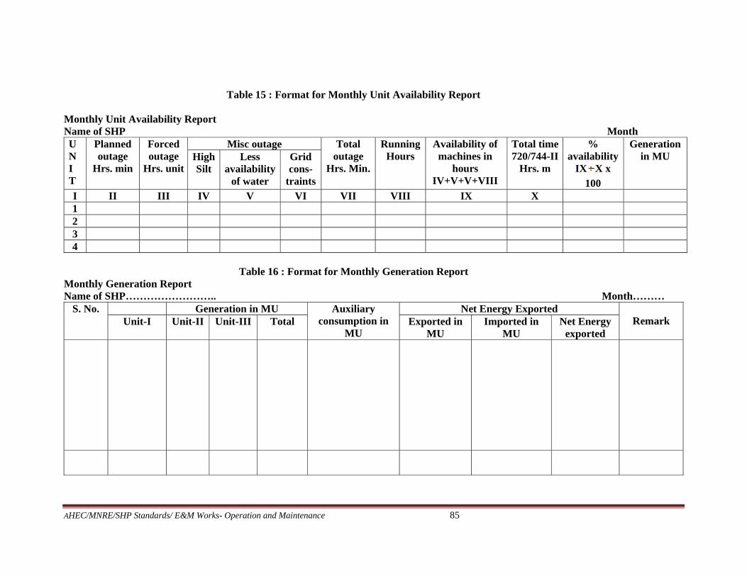
AHEC/MNRE/SHP Standards/ E&M Works- Operation and Maintenance 85
Table 15 : Format for Monthly Unit Availability Report Monthly Unit Availability Report Name of SHP Month U N I T
Planned outage
Hrs. min
Forced outage
Hrs. unit
Misc outage Total outage
Hrs. Min.
Running Hours
Availability of machines in
hours IV+V+V+VIII
Total time 720/744-II
Hrs. m
% availability
IX X x
100
Generation in MU High
Silt Less
availability of water
Grid cons-
traints
I II III IV V VI VII VIII IX X 1 2 3 4
Table 16 : Format for Monthly Generation Report
Monthly Generation Report Name of SHP…………………….. Month………
S. No. Generation in MU Auxiliary consumption in
MU
Net Energy Exported Remark Unit-I Unit-II Unit-III Total Exported in
MU Imported in
MU Net Energy
exported

AHEC/MNRE/SHP Standards/ E&M Works- Operation and Maintenance 86
Table 17: Format for Monthly Tripping Report Monthly Tripping Report Name of SHP Month S. No.
Name of unit/ line Type of Tripping Tripping report no…….. date Remark/comments (if any)
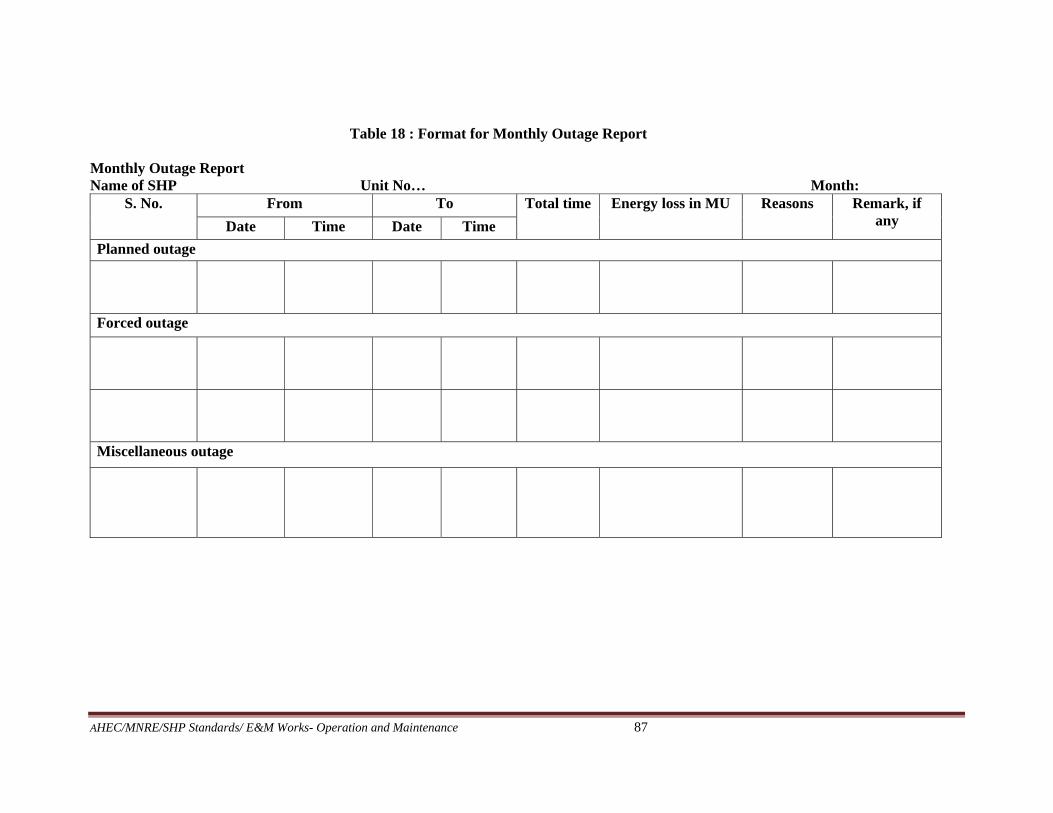
AHEC/MNRE/SHP Standards/ E&M Works- Operation and Maintenance 87
Table 18 : Format for Monthly Outage Report Monthly Outage Report Name of SHP Unit No… Month:
S. No. From To Total time Energy loss in MU Reasons Remark, if any Date Time Date Time
Planned outage
Forced outage
Miscellaneous outage

AHEC/MNRE/SHP Standards/ E&M Works- Operation and Maintenance 88
Table 19: Format for Monthly Deemed Generation Report Monthly Deemed Generation Report Name of SHP: Month:
S. No.
Unit No.
Date Constraints/ Backing down code
Time Backing down period
Capacity backed
down, in MW
Energy Loss (MU)
Total Generation Loss During the
Day (MU)
Spillage energy during the day (MU)
Deemed Generation
(MU) From To