sr en 13445 part 2
DESCRIPTION
Unfired pressure vessels - Part 2: MaterialsTRANSCRIPT
EUROPEAN STANDARD
NORME EUROPÉENNE
EUROPÄISCHE NORM
FINAL DRAFTprEN 13445-2
March 2002
ICS 23.020.30
English version
Unfired pressure vessels - Part 2: Materials
Récipients sous pression non soumis à la flamme - Partie2: Matériaux
Unbefeuerte Druckbehälter - Teil 2: Werkstoffe
This draft European Standard is submitted to CEN members for formal vote. It has been drawn up by the Technical Committee CEN/TC 54.
If this draft becomes a European Standard, CEN members are bound to comply with the CEN/CENELEC Internal Regulations whichstipulate the conditions for giving this European Standard the status of a national standard without any alteration.
This draft European Standard was established by CEN in three official versions (English, French, German). A version in any other languagemade by translation under the responsibility of a CEN member into its own language and notified to the Management Centre has the samestatus as the official versions.
CEN members are the national standards bodies of Austria, Belgium, Czech Republic, Denmark, Finland, France, Germany, Greece,Iceland, Ireland, Italy, Luxembourg, Malta, Netherlands, Norway, Portugal, Spain, Sweden, Switzerland and United Kingdom.
Warning : This document is not a European Standard. It is distributed for review and comments. It is subject to change without notice andshall not be referred to as a European Standard.
EUROPEAN COMMITTEE FOR STANDARDIZATIONC OM ITÉ EUR OP ÉEN DE NOR M ALIS AT IONEUROPÄISCHES KOMITEE FÜR NORMUNG
Management Centre: rue de Stassart, 36 B-1050 Brussels
© 2002 CEN All rights of exploitation in any form and by any means reservedworldwide for CEN national Members.
Ref. No. prEN 13445-2:2002 E
prEN 13445-2:2002 (E)Issue 1 (2002-05)
2
Contents
1 Scope ......................................................................................................................... .....................................4
2 Normative references .......................................................................................................... ..........................4
3 Terms, definitions, symbols and units ......................................................................................... ...............73.1 Terms and definitions....................................................................................................... .............................73.2 Symbols and units ........................................................................................................... ..............................8
4 Requirements for materials to be used for pressure-bearing parts .......................................................104.1 General..................................................................................................................... .....................................104.2 Special provisions .......................................................................................................... .............................124.2.1 Special properties........................................................................................................ ................................124.2.2 Design temperature above 20 °C............................................................................................ ....................124.2.3 Prevention of brittle fracture............................................................................................ ...........................134.2.4 Specific requirements for steels for fasteners ............................................................................ .............134.3 Technical delivery conditions............................................................................................... ......................134.3.1 European Standards........................................................................................................ ............................134.3.2 European Approval for Materials ........................................................................................... ....................144.3.3 Particular material appraisals............................................................................................ .........................144.3.4 Clad products ............................................................................................................. ..................................144.3.5 Welding consumables ....................................................................................................... ..........................144.4 Marking ..................................................................................................................... ....................................14
5 Requirements for materials to be used for non-pressure parts .............................................................14
Annex A (normative) Metallic materials for pressure equipment — Grouping system and Europeanstandardised steels ............................................................................................................ .........................15
A.1 Grouping system for metallic materials for pressure equipment...........................................................15A.2 European standardised steels grouped according to product forms....................................................17
Annex B (normative) Requirements for prevention of brittle fracture.................................................................29B.1 General..................................................................................................................... .....................................29B.2 Material selection and impact energy requirements........................................................................... .....29B.2.1 General................................................................................................................... .......................................29B.2.2 Method 1 — Code of practice ............................................................................................... ......................29B.2.3 Method 2 — Code of practice developed from fracture mechanics .......................................................34B.2.4 Method 3 — Fracture mechanics analysis .................................................................................... ............34B.3 General test requirements ................................................................................................... .......................36B.3.1 General................................................................................................................... .......................................36B.3.2 Sub-sized specimens ....................................................................................................... ...........................36B.4 Welds....................................................................................................................... ......................................37B.4.1 General................................................................................................................... .......................................37B.4.2 Welding procedure qualifications .......................................................................................... ....................37B.4.3 Production test plates .................................................................................................... .............................37
Annex C (informative) Technical delivery conditions for clad products for pressure purposes......................48C.1 Introductory note ........................................................................................................... ..............................48C.2 Requirements for the material ............................................................................................... .....................48C.3 Requirements for the deposited material..................................................................................... .............48C.4 Qualification of the cladding procedure..................................................................................... ...............49C.5 Production tests............................................................................................................ ...............................50
Annex D (informative) European Standards for steels for pressure vessels......................................................52
Annex ZA (informative) Clauses of this European Standard addressing essential safety requirementsor other provisions of EU directives........................................................................................... ...............53
Bibliography ................................................................................................................... ...........................................54

prEN 13445-2:2002 (E)Issue 1 (2002-05)
3
Foreword
This European Standard has been prepared by Technical Committee CEN /TC 54, "Unfired pressure vessels", theSecretariat of which is held by BSI.
This document is currently submitted to the Formal Vote.
This European Standard has been prepared under a mandate given to CEN by the European Commission and theEuropean Free Trade Association, and supports essential requirements of EU Directive 97/23/EC.
For relationship with EU Directive(s), see informative Annex ZA, which is an integral part of this Standard.
In this standard the Annexes A and B are informative.
This European Standard consists of the following Parts:
Part 1: General
Part 2: Materials
Part 3: Design
Part 4: Fabrication
Part 5: Inspection and testing
Part 6: Requirements for the design and fabrication of pressure vessels and pressure parts constructed fromspheroidal graphite cast iron
prCR 13445-7, Unfired pressure vessels - Part 7: Guidance on the use of conformity assessment procedures
prEN 13445-2:2002 (E)Issue 1 (2002-05)
4
1 Scope
This document specifies the requirements for materials (including clad materials) for unfired pressure vessels andsupports which are covered by EN 13445-1 and manufactured from metallic materials; it is currently limited tosteels with sufficient ductility. This document is not applicable in the creep range.
NOTE Other materials will be added later by amendments.
It specifies the requirements for the selection, inspection, testing and marking of metallic materials for thefabrication of unfired pressure vessels.
This document does not give provisions for material requirements and material selection for vessels designed usingDesign by Analysis – Direct Route (DBA) of Annex B of EN 13445–3:2002.
2 Normative references
This European Standard incorporates by dated or undated reference, provisions from other publications. Thesenormative references are cited at the appropriate places in the text and the publications are listed hereafter. Fordated references, subsequent amendments to or revisions of any of these publications apply to this EuropeanStandard only when incorporated in it by amendment or revision. For undated references the latest edition of thepublication referred to applies (including amendments).
EN 288-3, Specification and approval of welding procedures for metallic material — Part 3: Welding proceduretests for the arc welding of steels.
prEN 764-1, Pressure equipment — Terminology — Part 1: Pressure, temperature, volume, nominal size.
prEN 764-2, Pressure equipment — Part 2: Quantities, symbols and units.
prEN 764-3, Pressure equipment — Part 3: Definition of parties involved.
EN 10028-1, Flat products made of steels for pressure purposes — Part 1: General requirements.
EN 10028-2, Flat products made of steels for pressure purposes — Part 2: Non-alloy and alloy steels with specifiedelevated temperature properties.
EN 10028-3, Flat products made of steels for pressure purposes — Part 3: Weldable fine grain steels, normalized.
EN 10028-4, Flat products made of steels for pressure purposes — Part 4: Nickel alloy steels with specified lowtemperature properties.
EN 10028-5, Flat products made of steels for pressure purposes — Part 5: Weldable fine grain steels,thermomechanically rolled.
prEN 13445-2:2002 (E)Issue 1 (2002-05)
5
EN 10028-6, Flat products made of steels for pressure purposes — Part 6: Weldable fine grain steels, quenchedand tempered.
EN 10028-7, Flat products made of steels for pressure purposes — Part 7: Stainless steels.
EN 10045-1, Metallic materials — Charpy impact test — Part 1: Test method.
EN 10164, Steel products with improved deformation properties perpendicular to the surface of the product —Technical delivery conditions.
EN 10204, Metallic products — Types of inspection documents.
EN 10213-1, Technical delivery conditions for steel castings for pressure purposes — Part 1: General.
EN 10213-2, Technical delivery conditions for steel castings for pressure purposes — Part 2: Steel grades for useat room temperature and elevated temperatures.
EN 10213-3, Technical delivery conditions for steel castings for pressure purposes — Part 3: Steel grades for useat low temperatures.
EN 10213-4, Technical delivery conditions for steel castings for pressure purposes — Part 4: Austenitic andaustenitic-ferritic steel grades.
prEN 10216-1, Seamless steel tubes for pressure purposes — Technical delivery conditions — Part 1: Non-alloysteel tubes with specified room temperature properties.
prEN 10216-2, Seamless steel tubes for pressure purposes — Technical delivery conditions — Part 2: Non-alloyand alloy steel tubes with specified elevated temperature properties.
prEN 10216-3, Seamless steel tubes for pressure purposes — Technical delivery conditions — Part 3: Alloy finegrain steel tubes
prEN 10216-4, Seamless steel tubes for pressure purposes — Technical delivery conditions — Part 4: Non-alloyand alloy steel tubes with specified low temperature properties.
prEN 10216-5, Seamless steel tubes for pressure purposes — Technical delivery conditions — Part 5: Stainlesssteel tubes.
prEN 10217-1, Welded steel tubes for pressure purposes — Technical delivery conditions — Part 1: Non-alloy steeltubes with specified room temperature properties.
prEN 10217-2, Welded steel tubes for pressure purposes — Technical delivery conditions — Part 2: Electricwelded non-alloy and alloy steel tubes with specified elevated temperature properties.
prEN 10217-3, Welded steel tubes for pressure purposes — Technical delivery conditions — Part 3: Alloy fine grainsteel tubes.
prEN 13445-2:2002 (E)Issue 1 (2002-05)
6
prEN 10217-4, Welded steel tubes for pressure purposes — Technical delivery conditions — Part 4: Electricwelded non-alloy steel tubes with specified low temperature properties.
prEN 10217-5, Welded steel tubes for pressure purposes — Technical delivery conditions — Part 5: Submergedarc welded non-alloy and alloy steel tubes with specified elevated temperature properties.
prEN 10217-6, Welded steel tubes for pressure purposes — Technical delivery conditions — Part 6: Submergedarc welded non-alloy steel tubes with specified low temperature properties.
prEN 10217-7, Welded steel tubes for pressure purposes — Technical delivery conditions — Part 7: Stainless steeltubes.
EN 10222-1, Steel forgings for pressure purposes — Part 1: General requirements for open die forgings.
EN 10222-2, Steel forgings for pressure purposes — Part 2: Ferritic and martensitic steels with specified elevatedtemperature properties.
EN 10222-3, Steel forgings for pressure purposes — Part 3: Nickel steels with specified low temperaturesproperties.
EN 10222-4, Steel forgings for pressures purposes — Part 4: Weldable fine grain steels with high proof strength.
EN 10222-5, Steel forgings for pressure purposes — Part 5: Martensitic, austenitic and austenitic-ferritic stainlesssteels.
prEN 10253-2, Butt welding pipe fittings — Part 2: Wrought carbon and ferritic alloy steel with specific inspectionrequirements.
EN 10269, Steels and nickel alloys for fasteners with specified elevated and/or low temperature properties.
EN 10272, Stainless steel bars for pressure purposes.
EN 10273, Hot rolled weldable steel bars for pressure purposes with specified elevated temperature properties.
EN 12074, Welding consumables — Quality requirements for manufacture, supply and distribution of consumablesfor welding and allied processes.
EN 13445-1, Unfired pressure vessels — Part 1: General.
EN 13445-3, Unfired pressure vessels – Part 3: Design.
EN 13445-4, Unfired pressure vessels – Part 4: Fabrication.
EN 13445-5, Unfired pressure vessels — Part 5: Inspection and testing.
prEN 13479-1, Welding consumables — Test methods and quality requirements for conformity evaluation ofconsumables — Part 1: Primary methods and evaluation.
EN ISO 2566-1, Steel — Conversion of elongation values — Part 1: Carbon and low alloy steels (ISO 2566-1:1984).
EN ISO 2566-2, Steel — Conversion of elongation values — Part 2: Austenitic steels (ISO 2566-2:1984).
CR ISO 15608, Welding — Guidelines for a metallic material grouping system (ISO/TR 15608:2000).
prEN 13445-2:2002 (E)Issue 1 (2002-05)
7
3 Terms, definitions, symbols and units
3.1 Terms and definitions
For the purposes of this European Standard the terms and definitions given in EN 13445-1, prEN 764-1,prEN 764-3 and the following terms and definitions shall apply.
3.1.1minimum metal temperature TM
the lowest temperature determined for any of the following conditions (also see 3.1.2, 3.1.3):
� normal operations;
� start up and shut down procedures;
� possible process upsets, such as flashings of fluid, which have an atmospheric boiling point below 0 °C;
� during pressure or leak testing.
3.1.2temperature adjustment term TS
relevant to the calculation of the design reference temperature TR and is dependent on the calculated tensilemembrane stress at the appropriate minimum metal temperature
NOTE 1 Values for TS are given in Table B.2-1.
NOTE 2 For tensile membrane stress reference is made to EN 13445-3, Annex C:2002-05.
3.1.3design reference temperature TR
the temperature used for determining the impact energy requirements and is determined by adding the temperatureadjustment tS to the minimum metal temperature tM:
TR = TM � TS
3.1.4impact test temperature TKV
the temperature at which the required resistance to impact energy has to be achieved (see clause B.2).
3.1.5impact rupture energy KVthe energy absorbed by a sample of material when subjected to a Charpy-V-notch test in accordance withEN 10045-1
3.1.6reference thickness eB
thickness of a component to be used to relate the design reference temperature TR of the component with itsrequired impact test temperature TKV , (see Table B.1-1 and Figures B.4-1 to B.4-5). For unwelded parts thereference thickness eB is equal to the nominal wall thickness (including corrosion allowance). For welded parts thereference thickness is defined in Table B.4-1.
prEN 13445-2:2002 (E)Issue 1 (2002-05)
8
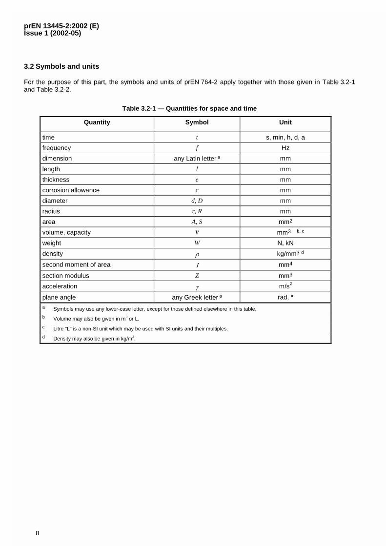
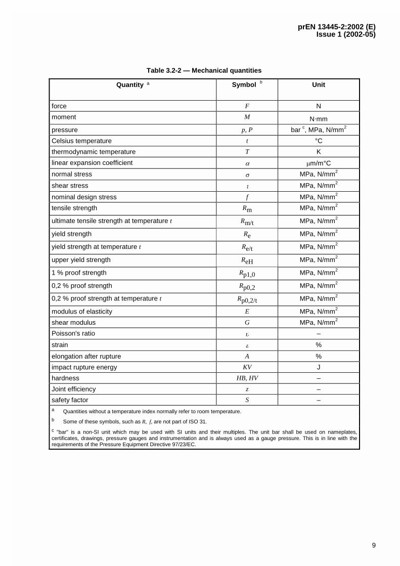
3.2 Symbols and units
For the purpose of this part, the symbols and units of prEN 764-2 apply together with those given in Table 3.2-1and Table 3.2-2.
Table 3.2-1 — Quantities for space and time
Quantity Symbol Unit
time t s, min, h, d, a
frequency f Hz
dimension any Latin letter a mm
length l mm
thickness e mm
corrosion allowance c mm
diameter d, D mm
radius r, R mm
area A, S mm2
volume, capacity V mm3 b, c
weight W N, kN
density � kg/mm3 d
second moment of area � mm4
section modulus Z mm3
acceleration � m/s2
plane angle any Greek letter a rad, °a Symbols may use any lower-case letter, except for those defined elsewhere in this table.
b Volume may also be given in m3 or L.
c Litre "L" is a non-SI unit which may be used with SI units and their multiples.
d Density may also be given in kg/m3.
prEN 13445-2:2002 (E)Issue 1 (2002-05)
9
Table 3.2-2 — Mechanical quantities
Quantity a Symbol b Unit
force F N
moment M N.mm
pressure p, P bar c, MPa, N/mm2
Celsius temperature t °C
thermodynamic temperature T K
linear expansion coefficient � �m/m°C
normal stress � MPa, N/mm2
shear stress � MPa, N/mm2
nominal design stress f MPa, N/mm2
tensile strength Rm MPa, N/mm2
ultimate tensile strength at temperature t Rm/t MPa, N/mm2
yield strength Re MPa, N/mm2
yield strength at temperature t Re/t MPa, N/mm2
upper yield strength ReH MPa, N/mm2
1 % proof strength Rp1,0 MPa, N/mm2
0,2 % proof strength Rp0,2 MPa, N/mm2
0,2 % proof strength at temperature t Rp0,2/t MPa, N/mm2
modulus of elasticity E MPa, N/mm2
shear modulus G MPa, N/mm2
Poisson's ratio � –
strain � %
elongation after rupture A %
impact rupture energy KV J
hardness HB, HV –
Joint efficiency z –
safety factor S –a Quantities without a temperature index normally refer to room temperature.
b Some of these symbols, such as R, f, are not part of ISO 31.
c "bar" is a non-SI unit which may be used with SI units and their multiples. The unit bar shall be used on nameplates,certificates, drawings, pressure gauges and instrumentation and is always used as a gauge pressure. This is in line with therequirements of the Pressure Equipment Directive 97/23/EC.
prEN 13445-2:2002 (E)Issue 1 (2002-05)
10
4 Requirements for materials to be used for pressure-bearing parts
4.1 General
4.1.1 Materials to be used for pressure-bearing parts shall meet the general requirements of 4.1 and the specialprovisions of 4.2, if applicable. Materials for pressure bearing parts shall be ordered complying with the technicaldelivery conditions in 4.3.
Marking of materials for pressure-bearing parts shall be performed in accordance with 4.4.
Materials shall be selected to be compatible with anticipated fabrication steps and to be suitable for the internal fluidand external environment. Both normal operating conditions and transient conditions occurring during fabrication,transport, testing and operation shall be taken into account when specifying the materials.
NOTE 1 The requirements of 4.1 and 4.2 should also be fulfilled when technical delivery conditions are developed forEuropean material standards, European approval of materials or particular material appraisals.
NOTE 2 When technical delivery conditions for pressure-bearing parts are developed, the structure and requirements ofprEN 764-4 should be met. Exceptions should be technically justified.
The materials shall be grouped in accordance with CR ISO 15608 to relate manufacturing and inspectionrequirements to generic material types.
NOTE 3 Materials have been allocated into these groups in accordance with their chemical composition and properties inrelation to manufacture and heat treatment after welding.
4.1.2 Materials for pressure-bearing parts compliant with the requirements of this European Standard shall becertified on the basis of EN 10204.
NOTE 4 The certification should be in accordance with prEN 764-5.
4.1.3 The materials shall be free from surface and internal defects which might impair their intended usability.
4.1.4 Steels shall have a specified minimum elongation after fracture measured on a gauge length
oSL 65,5o � (4.1-1)
in order to fulfil 4.1.1
where So = original cross sectional area within the gauge length
— � 14 % minimum elongation after fracture;
— � 16 % for the longitudinal direction, or where this is the less critical direction, the transverse direction.
However, lower elongation values than specified in 4.1 (e.g. fasteners or castings) may also be applied, providedthat appropriate measures are taken (see 4.1.1, NOTE 1) to compensate for these lower values and the specificrequirements are verifiable.
prEN 13445-2:2002 (E)Issue 1 (2002-05)
11
NOTE Examples for compensation:
� application of higher safety factors in design;
� performance of burst tests to demonstrate ductile material behaviour.
4.1.5 When measured on a gauge length other than that stated in 4.1.4, the minimum elongation after fractureshall be determined by converting the elongation given in 4.1.4 in accordance with
� EN ISO 2566-1 for carbon and low alloy steels;
� EN ISO 2566-2 for austenitic steels.
4.1.6 Steels shall have a specified minimum impact energy measured on a Charpy-V-notch impact test specimen(EN 10045-1) as follows:
� � 27 J for ferritic and 1,5 % to 5 % Ni alloy steels;
� � 40 J for steels of material group 8, 9.3 and 10
at a test temperature in accordance with Annex B, but not higher than 20 °C. The other requirements of Annex Bshall also apply.
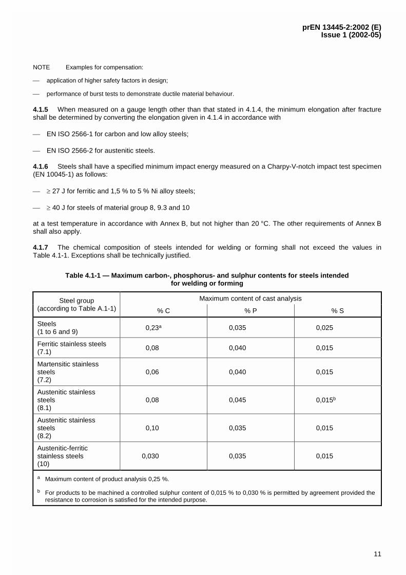
4.1.7 The chemical composition of steels intended for welding or forming shall not exceed the values inTable 4.1-1. Exceptions shall be technically justified.
Table 4.1-1 — Maximum carbon-, phosphorus- and sulphur contents for steels intendedfor welding or forming
Maximum content of cast analysisSteel group(according to Table A.1-1) % C % P % S
Steels(1 to 6 and 9)
0,23a 0,035 0,025
Ferritic stainless steels(7.1)
0,08 0,040 0,015
Martensitic stainlesssteels(7.2)
0,06 0,040 0,015
Austenitic stainlesssteels(8.1)
0,08 0,045 0,015b
Austenitic stainlesssteels(8.2)
0,10 0,035 0,015
Austenitic-ferriticstainless steels(10)
0,030 0,035 0,015
a Maximum content of product analysis 0,25 %.
b For products to be machined a controlled sulphur content of 0,015 % to 0,030 % is permitted by agreement provided theresistance to corrosion is satisfied for the intended purpose.
prEN 13445-2:2002 (E)Issue 1 (2002-05)
12
4.2 Special provisions
4.2.1 Special properties
4.2.1.1 General
Where the behaviour of a material can be affected by manufacturing processes or operating conditions, to anextent that would adversely affect the safety or service life of the pressure vessel, this shall be taken intoconsideration when specifying material.
Adverse effects may arise from:
� manufacturing processes: e.g. degree of cold forming and heat treatment;
� operating conditions: e.g. hydrogen embrittlement, corrosion, scaling and ageing behaviour of the materialafter cold forming.
4.2.1.2 Lamellar tearing
Where lamellar tearing due to the joint design and loading needs to be addressed, steels shall be used which haveimproved deformation properties perpendicular to the surface and verified in accordance with EN 10164.
NOTE For guidance see EN 1011-2.
4.2.2 Design temperature above 20 °C
4.2.2.1 A material shall only be used for pressure parts within the range of temperatures for which the materialproperties required by EN 13445-3 are defined in the technical specification for the material. If the technical deliverycondition does not contain the specific material values required for the allowable temperature TS the valuesrequired in EN 13445-3 for the design shall be determined by linear interpolation between the two adjacent values.Values shall not be rounded up.
For other than austenitic and austenitic-ferritic stainless steels, the specified value of ReH (Rp0,2) at room tempe-rature (RT) may be used for temperatures less than 50 °C. Interpolation between 50 °C and 100 °C shall beperformed with the values of RT and 100 °C and using 20 °C as the starting point for interpolation. Above 100 °Clinear interpolation shall be performed between the tabulated values given in the table.
4.2.2.2 As the impact properties may be affected by long or frequent holding of the material at elevatedtemperatures, it is presupposed that the temperatures and periods of exposure to elevated temperatures berecorded for review during in-service inspection. The influence of such exposure upon the lifetime expectancy shallbe estimated and recorded.
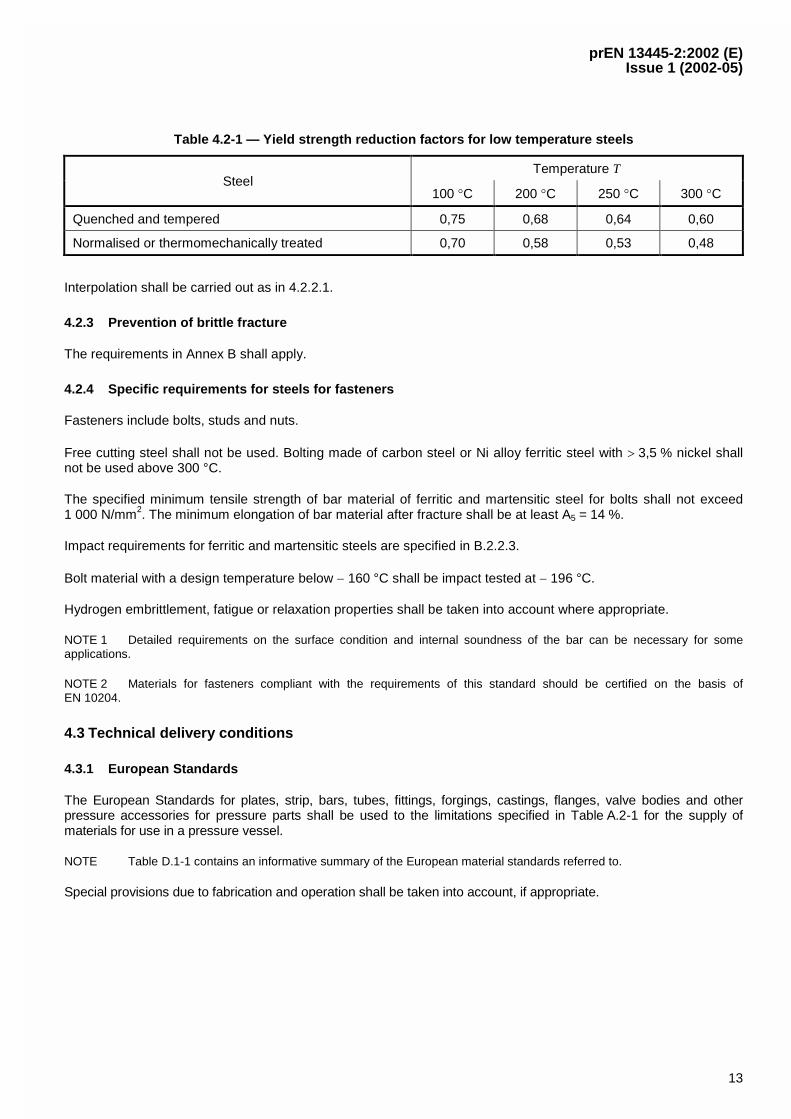
For operations such as drying and cleaning of pressure vessels, steels with specified low temperature propertiesbut without elevated temperature 0,2 % proof strength values may however be used at elevated temperatures fordrying and cleaning processes provided that the values of 0,2 % proof strength used in design calculations forelevated temperatures shall be obtained by multiplying the specified minimum yield strength values at 20 °C by thefactor given in Table 4.2-1.
prEN 13445-2:2002 (E)Issue 1 (2002-05)
13
Table 4.2-1 — Yield strength reduction factors for low temperature steels
Temperature TSteel
100 �C 200 �C 250 �C 300 �C
Quenched and tempered 0,75 0,68 0,64 0,60
Normalised or thermomechanically treated 0,70 0,58 0,53 0,48
Interpolation shall be carried out as in 4.2.2.1.
4.2.3 Prevention of brittle fracture
The requirements in Annex B shall apply.
4.2.4 Specific requirements for steels for fasteners
Fasteners include bolts, studs and nuts.
Free cutting steel shall not be used. Bolting made of carbon steel or Ni alloy ferritic steel with � 3,5 % nickel shallnot be used above 300 °C.
The specified minimum tensile strength of bar material of ferritic and martensitic steel for bolts shall not exceed1 000 N/mm2. The minimum elongation of bar material after fracture shall be at least A5 = 14 %.
Impact requirements for ferritic and martensitic steels are specified in B.2.2.3.
Bolt material with a design temperature below � 160 °C shall be impact tested at � 196 °C.
Hydrogen embrittlement, fatigue or relaxation properties shall be taken into account where appropriate.
NOTE 1 Detailed requirements on the surface condition and internal soundness of the bar can be necessary for someapplications.
NOTE 2 Materials for fasteners compliant with the requirements of this standard should be certified on the basis ofEN 10204.
4.3 Technical delivery conditions
4.3.1 European Standards
The European Standards for plates, strip, bars, tubes, fittings, forgings, castings, flanges, valve bodies and otherpressure accessories for pressure parts shall be used to the limitations specified in Table A.2-1 for the supply ofmaterials for use in a pressure vessel.
NOTE Table D.1-1 contains an informative summary of the European material standards referred to.
Special provisions due to fabrication and operation shall be taken into account, if appropriate.
prEN 13445-2:2002 (E)Issue 1 (2002-05)
14
4.3.2 European Approval for Materials
A material specified in an EMDS for pressure vessels shall only be used within its range of application.
4.3.3 Particular material appraisals
Materials other than those specified in 4.3.1 and 4.3.2 may also be used provided that they have been accepted by aparticular material appraisal.
4.3.4 Clad products
Technical delivery conditions for clad products for pressure parts shall be in accordance with the requirements ofAnnex C.
NOTE 1 European Standards specifying technical delivery conditions for clad products for pressure purposes are notcurrently available.
NOTE 2 Examples of national documents covering technical delivery condition for clad steels are given in [2] to [4].
4.3.5 Welding consumables
Technical delivery conditions for welding consumables used for the welding of pressure parts and attachments topressure parts shall be in accordance with EN 12074 and prEN 13479-1.
NOTE Equivalent national/international specifications are accepted which fulfil the same criteria with respect to therequirements for the QA-System and the requirements for manufacture, supply, distribution, test methods and evaluationconsumables.
4.4 Marking
The marking of the products or delivery units shall ensure traceability between the product or delivery unit and theinspection documents.
For European standardised materials the marking shall fulfil the requirements of the relevant product standard.
For materials not contained in a European Standard the marking shall at least contain:
� the material specification (reference, material designation);
� the manufacturers name or mark;
� the stamp of the inspection representative, if applicable.
For material supplied with specific inspection the marking shall include an identification which permits thecorrelation between the product or delivery unit and the relevant inspection document.
5 Requirements for materials to be used for non-pressure parts
For non-pressure parts, e.g. for supporting lugs, skirts, baffles and similar parts welded to pressure vessels,material shall be used which are supplied to material specifications covering at least requirements for the chemicalcomposition and the tensile properties. These materials shall not limit the operating conditions of the material towhich they are attached.
prEN 13445-2:2002 (E)Issue 1 (2002-05)
15
Annex A (normative)
Metallic materials for pressure equipment — Grouping system andEuropean standardised steels
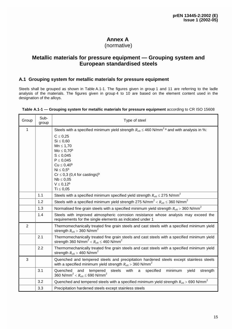
A.1 Grouping system for metallic materials for pressure equipment
Steels shall be grouped as shown in Table A.1-1. The figures given in group 1 and 11 are referring to the ladleanalysis of the materials. The figures given in group 4 to 10 are based on the element content used in thedesignation of the alloys.
Table A.1-1 — Grouping system for metallic materials for pressure equipment according to CR ISO 15608
Group Sub-group
Type of steel
1 Steels with a specified minimum yield strength ReH 460 N/mm2 a and with analysis in %:
C 0,25Si 0,60Mn 1,70Mo 0,70b
S 0,045P 0,045Cu 0,40b
Ni 0,5b
Cr 0,3 (0,4 for castings)b
Nb 0,05V 0,12b
Ti 0,05
1.1 Steels with a specified minimum specified yield strength ReH 275 N/mm2
1.2 Steels with a specified minimum yield strength 275 N/mm2 ReH 360 N/mm2
1.3 Normalised fine grain steels with a specified minimum yield strength ReH � 360 N/mm2
1.4 Steels with improved atmospheric corrosion resistance whose analysis may exceed therequirements for the single elements as indicated under 1
2 Thermomechanically treated fine grain steels and cast steels with a specified minimum yieldstrength ReH � 360 N/mm2
2.1 Thermomechanically treated fine grain steels and cast steels with a specified minimum yieldstrength 360 N/mm2 ReH 460 N/mm2
2.2 Thermomechanically treated fine grain steels and cast steels with a specified minimum yieldstrength ReH � 460 N/mm2
3 Quenched and tempered steels and precipitation hardened steels except stainless steelswith a specified minimum yield strength ReH � 360 N/mm2
3.1 Quenched and tempered steels with a specified minimum yield strength360 N/mm2 ReH 690 N/mm2
3.2 Quenched and tempered steels with a specified minimum yield strength ReH � 690 N/mm2
3.3 Precipitation hardened steels except stainless steels
prEN 13445-2:2002 (E)Issue 1 (2002-05)
16
Group Sub-group
Type of steel
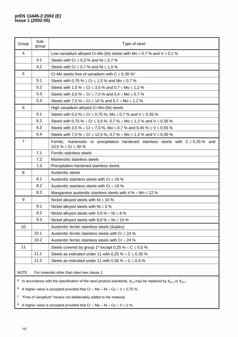
4 Low vanadium alloyed Cr-Mo-(Ni) steels with Mo 0,7 % and V 0,1 %
4.1 Steels with Cr 0,3 % and Ni 0,7 %
4.2 Steels with Cr 0,7 % and Ni 1,5 %
5 Cr-Mo steels free of vanadium with C 0,35 %c
5.1 Steels with 0,75 % Cr 1,5 % and Mo 0,7 %
5.2 Steels with 1,5 % Cr 3,5 % and 0,7 Mo 1,2 %
5.3 Steels with 3,5 % Cr 7,0 % and 0,4 Mo 0,7 %
5.4 Steels with 7,0 % Cr 10 % and 0,7 Mo 1,2 %
6 High vanadium alloyed Cr-Mo-(Ni) steels
6.1 Steels with 0,3 % Cr 0,75 %, Mo 0,7 % and V 0,35 %
6.2 Steels with 0,75 % Cr 3,5 %, 0,7 % Mo 1,2 % and V 0,35 %
6.3 Steels with 3,5 % Cr 7,0 %, Mo 0,7 % and 0,45 % V 0,55 %
6.4 Steels with 7,0 % Cr 12,5 %, 0,7 % Mo 1,2 % and V 0,35 %
7 Ferritic, martensitic or precipitation hardened stainless steels with C 0,35 % and10,5 % Cr 30 %
7.1 Ferritic stainless steels
7.2 Martensitic stainless steels
7.3 Precipitation hardened stainless steels
8 Austenitic steels
8.1 Austenitic stainless steels with Cr 19 %
8.2 Austenitic stainless steels with Cr � 19 %
8.3 Manganese austenitic stainless steels with 4 % Mn 12 %
9 Nickel alloyed steels with Ni 10 %
9.1 Nickel alloyed steels with Ni 3 %
9.2 Nickel alloyed steels with 3,0 % Ni 8 %
9.3 Nickel alloyed steels with 8,0 % Ni 10 %
10 Austenitic ferritic stainless steels (duplex)
10.1 Austenitic ferritic stainless steels with Cr 24 %
10.2 Austenitic ferritic stainless steels with Cr � 24 %
11 Steels covered by group 1d except 0,25 % C 0,5 %
11.1 Steels as indicated under 11 with 0,25 % C 0,35 %
11.2 Steels as indicated under 11 with 0,35 % C 0,5 %
NOTE For materials other than steel see clause 1.
a In accordance with the specification of the steel product standards, ReH may be replaced by Rp0,2 or Rp0.5.
b A higher value is accepted provided that Cr � Mo � Ni � Cu � V 0,75 %.
c "Free of vanadium" means not deliberately added to the material.
d A higher value is accepted provided that Cr � Mo � Ni � Cu � V 1 %.

prEN 13445-2:2002 (E)Issue 1 (2002-05)
17
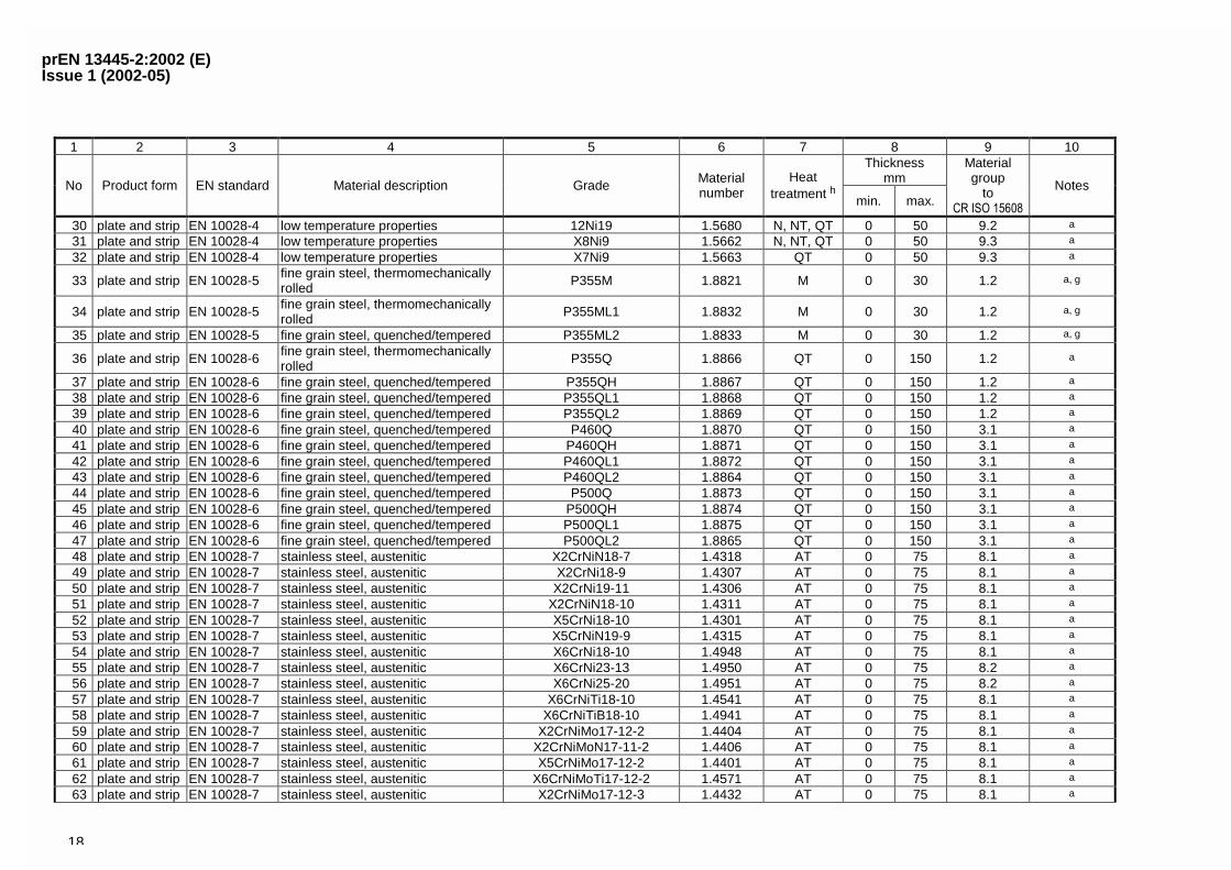
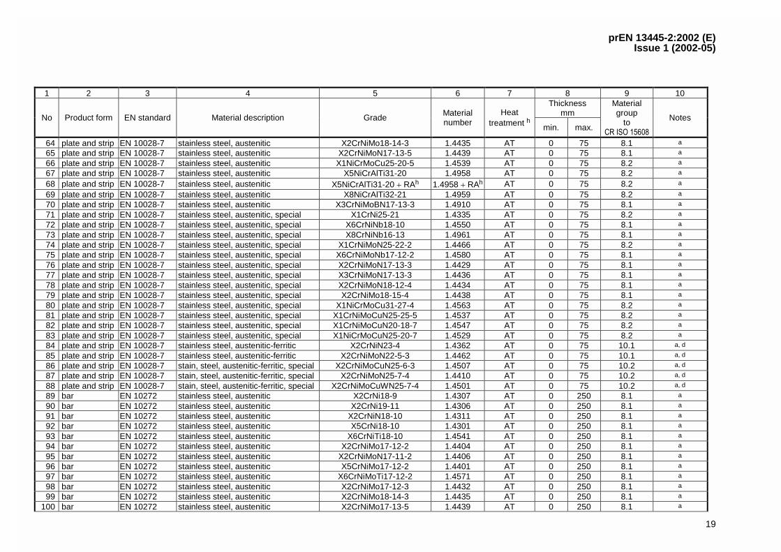
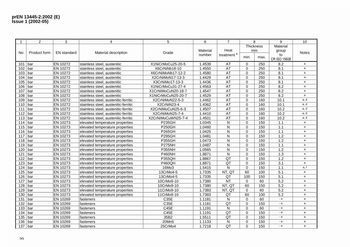
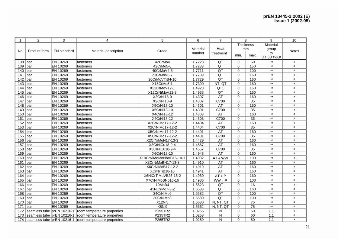
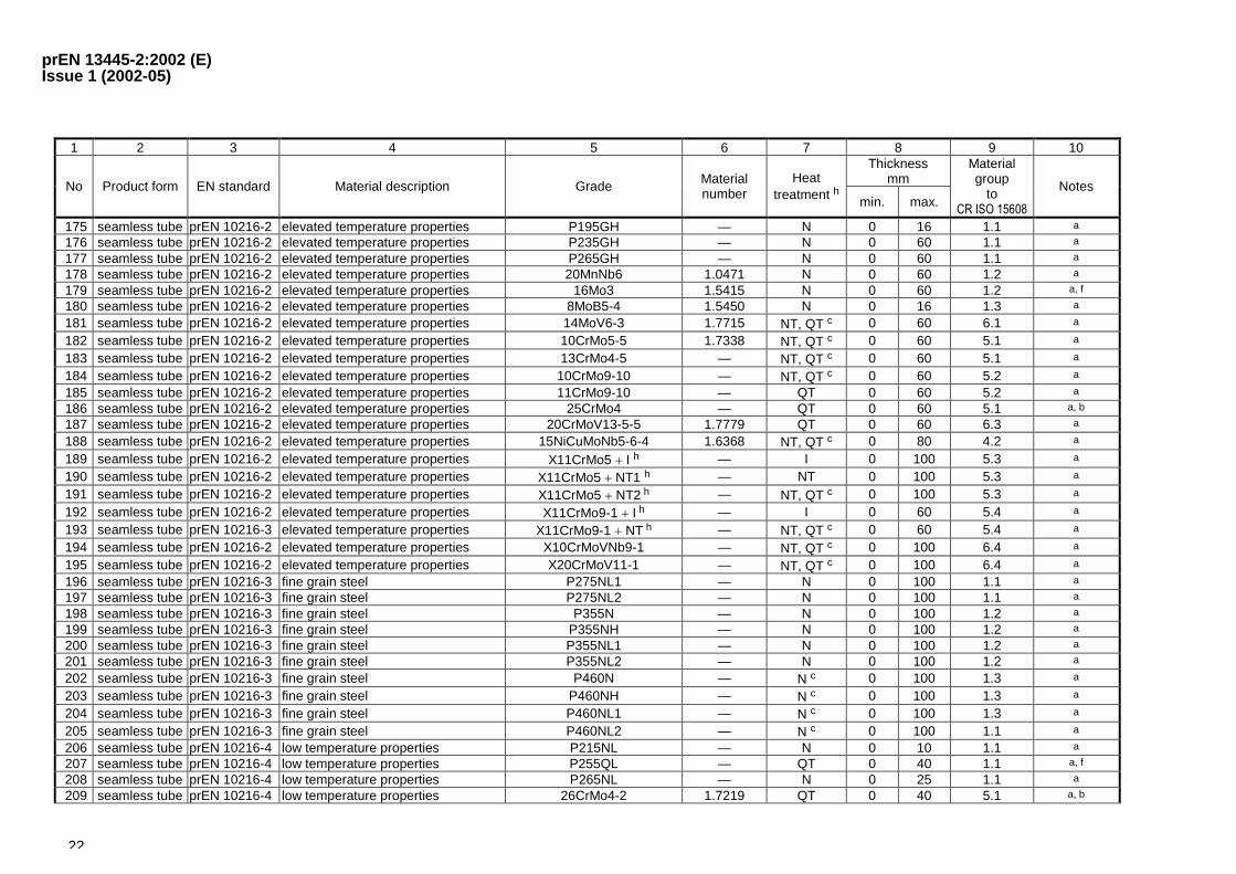
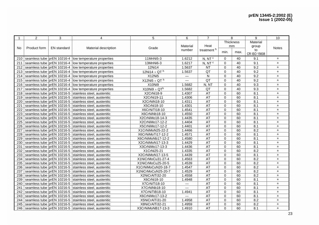
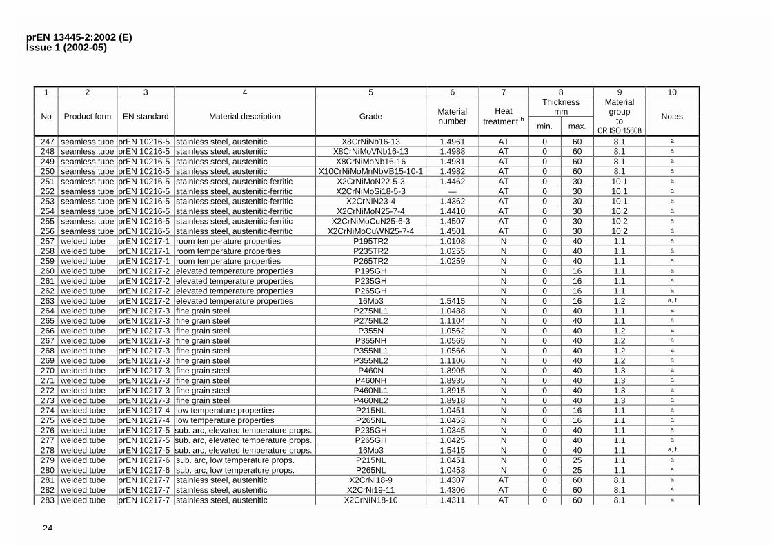
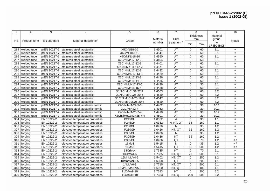
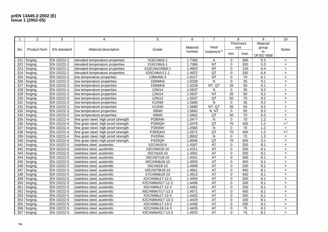
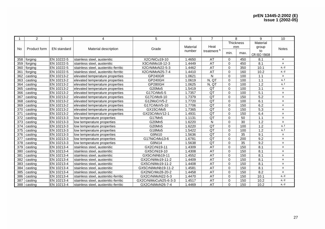
A.2 European standardised steels grouped according to product forms
Steel products in accordance with Table A.2-1 will fulfil the requirements for pressure parts of pressure vessels covered by this European Standard.
A.2-1 — European standardised steels grouped according to product forms
1 2 3 4 5 6 7 8 9 10Thickness
mmNo Product form EN standard Material description Grade Materialnumber
Heattreatment h min. max.
Materialgroup
to����������
Notes
1 plate and strip EN 10028-2 elevated temperature properties P235GH 1.0345 N 0 150 1.1 a
2 plate and strip EN 10028-2 elevated temperature properties P265GH 1.0425 N 0 150 1.1 a
3 plate and strip EN 10028-2 elevated temperature properties P295GH 1.0481 N 0 150 1.2 a
4 plate and strip EN 10028-2 elevated temperature properties P355GH 1.0473 N 0 150 1.2 a
5 plate and strip EN 10028-2 elevated temperature properties 16Mo3 1.5415 N 0 150 1.1 a, f
6 plate and strip EN 10028-2 elevated temperature properties 13CrMo4-5 1.7335 NT 60 60 5.1 a
7 plate and strip EN 10028-2 elevated temperature properties 13CrMo4-5 1.7335 NT, QT 100 100 5.1 a
8 plate and strip EN 10028-2 elevated temperature properties 13CrMo4-5 1.7335 QT 0 150 5.1 a
9 plate and strip EN 10028-2 elevated temperature properties 10CrMo9-10 1.7380 NT 0 60 5.2 a
10 plate and strip EN 10028-2 elevated temperature properties 10CrMo9-10 1.7380 NT, QT 60 100 5.2 a
11 plate and strip EN 10028-2 elevated temperature properties 10CrMo9-10 1.7380 QT 100 150 5.2 a
12 plate and strip EN 10028-2 elevated temperature properties 11CrMo9-10 1.7383 NT, QT 0 60 5.2 a
13 plate and strip EN 10028-2 elevated temperature properties 11CrMo9-10 1.7383 QT 60 100 5.2 a
14 plate and strip EN 10028-3 fine grain steel normalised P275N 1.0486 N 0 150 1.1 a
15 plate and strip EN 10028-3 fine grain steel normalised P275NH 1.0487 N 0 150 1.1 a
16 plate and strip EN 10028-3 fine grain steel normalised P275NL1 1.0488 N 0 150 1.1 a
17 plate and strip EN 10028-3 fine grain steel normalised P275NL2 1.1104 N 0 150 1.1 a
18 plate and strip EN 10028-3 fine grain steel normalised P355N 1.0562 N 0 150 1.2 a
19 plate and strip EN 10028-3 fine grain steel normalised P355NH 1.0565 N 0 150 1.2 a
20 plate and strip EN 10028-3 fine grain steel normalised P355NL1 1.0566 N 0 150 1.2 a
21 plate and strip EN 10028-3 fine grain steel normalised P355NL2 1.1106 N 0 150 1.2 a
22 plate and strip EN 10028-3 fine grain steel normalised P460N 1.8905 N 0 150 1.3 a
23 plate and strip EN 10028-3 fine grain steel normalised P460NH 1.8935 N 0 150 1.3 a
24 plate and strip EN 10028-3 fine grain steel normalised P460NL1 1.8915 N 0 150 1.3 a
25 plate and strip EN 10028-3 fine grain steel normalised P460NL2 1.8918 N 0 150 1.3 a
26 plate and strip EN 10028-4 low temperature properties 11MnNi5-3 1.6212 N, NT 0 50 9.1 a
27 plate and strip EN 10028-4 low temperature properties 13MnNi6-3 1.6217 N, NT 0 50 9.1 a
28 plate and strip EN 10028-4 low temperature properties 15NiMn6 1.6228 N, NT, QT 0 50 9.1 a
29 plate and strip EN 10028-4 low temperature properties 12Ni14 1.5637 N, NT, QT 0 50 9.2 a
prEN 13445-2:2002 (E)Issue 1 (2002-05)
18
1 2 3 4 5 6 7 8 9 10Thickness
mmNo Product form EN standard Material description Grade Materialnumber
Heattreatment h min. max.
Materialgroup
to����������
Notes
30 plate and strip EN 10028-4 low temperature properties 12Ni19 1.5680 N, NT, QT 0 50 9.2 a
31 plate and strip EN 10028-4 low temperature properties X8Ni9 1.5662 N, NT, QT 0 50 9.3 a
32 plate and strip EN 10028-4 low temperature properties X7Ni9 1.5663 QT 0 50 9.3 a
33 plate and strip EN 10028-5 fine grain steel, thermomechanicallyrolled P355M 1.8821 M 0 30 1.2 a, g
34 plate and strip EN 10028-5 fine grain steel, thermomechanicallyrolled P355ML1 1.8832 M 0 30 1.2 a, g
35 plate and strip EN 10028-5 fine grain steel, quenched/tempered P355ML2 1.8833 M 0 30 1.2 a, g
36 plate and strip EN 10028-6 fine grain steel, thermomechanicallyrolled P355Q 1.8866 QT 0 150 1.2 a
37 plate and strip EN 10028-6 fine grain steel, quenched/tempered P355QH 1.8867 QT 0 150 1.2 a
38 plate and strip EN 10028-6 fine grain steel, quenched/tempered P355QL1 1.8868 QT 0 150 1.2 a
39 plate and strip EN 10028-6 fine grain steel, quenched/tempered P355QL2 1.8869 QT 0 150 1.2 a
40 plate and strip EN 10028-6 fine grain steel, quenched/tempered P460Q 1.8870 QT 0 150 3.1 a
41 plate and strip EN 10028-6 fine grain steel, quenched/tempered P460QH 1.8871 QT 0 150 3.1 a
42 plate and strip EN 10028-6 fine grain steel, quenched/tempered P460QL1 1.8872 QT 0 150 3.1 a
43 plate and strip EN 10028-6 fine grain steel, quenched/tempered P460QL2 1.8864 QT 0 150 3.1 a
44 plate and strip EN 10028-6 fine grain steel, quenched/tempered P500Q 1.8873 QT 0 150 3.1 a
45 plate and strip EN 10028-6 fine grain steel, quenched/tempered P500QH 1.8874 QT 0 150 3.1 a
46 plate and strip EN 10028-6 fine grain steel, quenched/tempered P500QL1 1.8875 QT 0 150 3.1 a
47 plate and strip EN 10028-6 fine grain steel, quenched/tempered P500QL2 1.8865 QT 0 150 3.1 a
48 plate and strip EN 10028-7 stainless steel, austenitic X2CrNiN18-7 1.4318 AT 0 75 8.1 a
49 plate and strip EN 10028-7 stainless steel, austenitic X2CrNi18-9 1.4307 AT 0 75 8.1 a
50 plate and strip EN 10028-7 stainless steel, austenitic X2CrNi19-11 1.4306 AT 0 75 8.1 a
51 plate and strip EN 10028-7 stainless steel, austenitic X2CrNiN18-10 1.4311 AT 0 75 8.1 a
52 plate and strip EN 10028-7 stainless steel, austenitic X5CrNi18-10 1.4301 AT 0 75 8.1 a
53 plate and strip EN 10028-7 stainless steel, austenitic X5CrNiN19-9 1.4315 AT 0 75 8.1 a
54 plate and strip EN 10028-7 stainless steel, austenitic X6CrNi18-10 1.4948 AT 0 75 8.1 a
55 plate and strip EN 10028-7 stainless steel, austenitic X6CrNi23-13 1.4950 AT 0 75 8.2 a
56 plate and strip EN 10028-7 stainless steel, austenitic X6CrNi25-20 1.4951 AT 0 75 8.2 a
57 plate and strip EN 10028-7 stainless steel, austenitic X6CrNiTi18-10 1.4541 AT 0 75 8.1 a
58 plate and strip EN 10028-7 stainless steel, austenitic X6CrNiTiB18-10 1.4941 AT 0 75 8.1 a
59 plate and strip EN 10028-7 stainless steel, austenitic X2CrNiMo17-12-2 1.4404 AT 0 75 8.1 a
60 plate and strip EN 10028-7 stainless steel, austenitic X2CrNiMoN17-11-2 1.4406 AT 0 75 8.1 a
61 plate and strip EN 10028-7 stainless steel, austenitic X5CrNiMo17-12-2 1.4401 AT 0 75 8.1 a
62 plate and strip EN 10028-7 stainless steel, austenitic X6CrNiMoTi17-12-2 1.4571 AT 0 75 8.1 a
63 plate and strip EN 10028-7 stainless steel, austenitic X2CrNiMo17-12-3 1.4432 AT 0 75 8.1 a
prEN 13445-2:2002 (E)Issue 1 (2002-05)
19
1 2 3 4 5 6 7 8 9 10Thickness
mmNo Product form EN standard Material description Grade Materialnumber
Heattreatment h min. max.
Materialgroup
to����������
Notes
64 plate and strip EN 10028-7 stainless steel, austenitic X2CrNiMo18-14-3 1.4435 AT 0 75 8.1 a
65 plate and strip EN 10028-7 stainless steel, austenitic X2CrNiMoN17-13-5 1.4439 AT 0 75 8.1 a
66 plate and strip EN 10028-7 stainless steel, austenitic X1NiCrMoCu25-20-5 1.4539 AT 0 75 8.2 a
67 plate and strip EN 10028-7 stainless steel, austenitic X5NiCrAlTi31-20 1.4958 AT 0 75 8.2 a
68 plate and strip EN 10028-7 stainless steel, austenitic X5NiCrAlTi31-20 � RAh 1.4958 � RAh AT 0 75 8.2 a
69 plate and strip EN 10028-7 stainless steel, austenitic X8NiCrAlTi32-21 1.4959 AT 0 75 8.2 a
70 plate and strip EN 10028-7 stainless steel, austenitic X3CrNiMoBN17-13-3 1.4910 AT 0 75 8.1 a
71 plate and strip EN 10028-7 stainless steel, austenitic, special X1CrNi25-21 1.4335 AT 0 75 8.2 a
72 plate and strip EN 10028-7 stainless steel, austenitic, special X6CrNiNb18-10 1.4550 AT 0 75 8.1 a
73 plate and strip EN 10028-7 stainless steel, austenitic, special X8CrNiNb16-13 1.4961 AT 0 75 8.1 a
74 plate and strip EN 10028-7 stainless steel, austenitic, special X1CrNiMoN25-22-2 1.4466 AT 0 75 8.2 a
75 plate and strip EN 10028-7 stainless steel, austenitic, special X6CrNiMoNb17-12-2 1.4580 AT 0 75 8.1 a
76 plate and strip EN 10028-7 stainless steel, austenitic, special X2CrNiMoN17-13-3 1.4429 AT 0 75 8.1 a
77 plate and strip EN 10028-7 stainless steel, austenitic, special X3CrNiMoN17-13-3 1.4436 AT 0 75 8.1 a
78 plate and strip EN 10028-7 stainless steel, austenitic, special X2CrNiMoN18-12-4 1.4434 AT 0 75 8.1 a
79 plate and strip EN 10028-7 stainless steel, austenitic, special X2CrNiMo18-15-4 1.4438 AT 0 75 8.1 a
80 plate and strip EN 10028-7 stainless steel, austenitic, special X1NiCrMoCu31-27-4 1.4563 AT 0 75 8.2 a
81 plate and strip EN 10028-7 stainless steel, austenitic, special X1CrNiMoCuN25-25-5 1.4537 AT 0 75 8.2 a
82 plate and strip EN 10028-7 stainless steel, austenitic, special X1CrNiMoCuN20-18-7 1.4547 AT 0 75 8.2 a
83 plate and strip EN 10028-7 stainless steel, austenitic, special X1NiCrMoCuN25-20-7 1.4529 AT 0 75 8.2 a
84 plate and strip EN 10028-7 stainless steel, austenitic-ferritic X2CrNiN23-4 1.4362 AT 0 75 10.1 a, d
85 plate and strip EN 10028-7 stainless steel, austenitic-ferritic X2CrNiMoN22-5-3 1.4462 AT 0 75 10.1 a, d
86 plate and strip EN 10028-7 stain, steel, austenitic-ferritic, special X2CrNiMoCuN25-6-3 1.4507 AT 0 75 10.2 a, d
87 plate and strip EN 10028-7 stain, steel, austenitic-ferritic, special X2CrNiMoN25-7-4 1.4410 AT 0 75 10.2 a, d
88 plate and strip EN 10028-7 stain, steel, austenitic-ferritic, special X2CrNiMoCuWN25-7-4 1.4501 AT 0 75 10.2 a, d
89 bar EN 10272 stainless steel, austenitic X2CrNi18-9 1.4307 AT 0 250 8.1 a
90 bar EN 10272 stainless steel, austenitic X2CrNi19-11 1.4306 AT 0 250 8.1 a
91 bar EN 10272 stainless steel, austenitic X2CrNiN18-10 1.4311 AT 0 250 8.1 a
92 bar EN 10272 stainless steel, austenitic X5CrNi18-10 1.4301 AT 0 250 8.1 a
93 bar EN 10272 stainless steel, austenitic X6CrNiTi18-10 1.4541 AT 0 250 8.1 a
94 bar EN 10272 stainless steel, austenitic X2CrNiMo17-12-2 1.4404 AT 0 250 8.1 a
95 bar EN 10272 stainless steel, austenitic X2CrNiMoN17-11-2 1.4406 AT 0 250 8.1 a
96 bar EN 10272 stainless steel, austenitic X5CrNiMo17-12-2 1.4401 AT 0 250 8.1 a
97 bar EN 10272 stainless steel, austenitic X6CrNiMoTi17-12-2 1.4571 AT 0 250 8.1 a
98 bar EN 10272 stainless steel, austenitic X2CrNiMo17-12-3 1.4432 AT 0 250 8.1 a
99 bar EN 10272 stainless steel, austenitic X2CrNiMo18-14-3 1.4435 AT 0 250 8.1 a
100 bar EN 10272 stainless steel, austenitic X2CrNiMo17-13-5 1.4439 AT 0 250 8.1 a
prEN 13445-2:2002 (E)Issue 1 (2002-05)
20
1 2 3 4 5 6 7 8 9 10Thickness
mmNo Product form EN standard Material description Grade Materialnumber
Heattreatment h min. max.
Materialgroup
to����������
Notes
101 bar EN 10272 stainless steel, austenitic X1NiCrMoCu25-20-5 1.4539 AT 0 250 8.2 a
102 bar EN 10272 stainless steel, austenitic X6CrNiNb18-10 1.4550 AT 0 250 8.1 a
103 bar EN 10272 stainless steel, austenitic X6CrNiMoNb17-12-2 1.4580 AT 0 250 8.1 a
104 bar EN 10272 stainless steel, austenitic X2CrNiMoN17-13-3 1.4429 AT 0 250 8.1 a
105 bar EN 10272 stainless steel, austenitic X3CrNiMo17-13-3 1.4436 AT 0 250 8.1 a
106 bar EN 10272 stainless steel, austenitic X1NiCrMoCu31-27-4 1.4563 AT 0 250 8.2 a
107 bar EN 10272 stainless steel, austenitic X1CrNiMoCuN20-18-7 1.4547 AT 0 250 8.2 a
108 bar EN 10272 stainless steel, austenitic X1NiCrMoCuN25-20-7 1.4529 AT 0 250 8.2 a
109 bar EN 10272 stainless steel, austenitic-ferritic X2CrNiMoN22-5-3 1.4462 AT 0 160 10.1 a, d
110 bar EN 10272 stainless steel, austenitic-ferritic X2CrNiN23-4 1.4362 AT 0 160 10.1 a, d
111 bar EN 10272 stainless steel, austenitic-ferritic X2CrNiMoCuN25-6-3 1.4507 AT 0 160 10.2 a, d
112 bar EN 10272 stainless steel, austenitic-ferritic X2CrNiMoN25-7-4 1.4410 AT 0 160 10.2 a, d
113 bar EN 10272 stainless steel, austenitic-ferritic X2CrNiMoCuWN25-7-4 1.4501 AT 0 160 10.2 a, d
114 bar EN 10273 elevated temperature properties P235GH 1.0345 N 0 150 1.1 a
115 bar EN 10273 elevated temperature properties P250GH 1.0460 N 0 150 1.1 a
116 bar EN 10273 elevated temperature properties P265GH 1.0425 N 0 150 1.1 a
117 bar EN 10273 elevated temperature properties P295GH 1.0481 N 0 150 1.2 a
118 bar EN 10273 elevated temperature properties P355GH 1.0473 N 0 150 1.2 a
119 bar EN 10273 elevated temperature properties P275NH 1.0487 N 0 150 1.1 a
120 bar EN 10273 elevated temperature properties P355NH 1.0565 N 0 150 1.2 a
121 bar EN 10273 elevated temperature properties P460NH 1.8871 N 0 150 1.3 a
122 bar EN 10273 elevated temperature properties P355QH 1.8867 QT 0 150 1.2 a
123 bar EN 10273 elevated temperature properties P460QH 1.8871 QT 0 150 3.1 a
124 bar EN 10273 elevated temperature properties 16Mo3 1.5415 N 0 150 1.1 a, f
125 bar EN 10273 elevated temperature properties 13CrMo4-5 1.7335 NT, QT 60 100 5.1 a
126 bar EN 10273 elevated temperature properties 13CrMo4-5 1.7335 QT 100 150 5.1 a
127 bar EN 10273 elevated temperature properties 10CrMo9-10 1.7380 NT 0 60 5.2 a
128 bar EN 10273 elevated temperature properties 10CrMo9-10 1.7380 NT, QT 60 150 5.2 a
129 bar EN 10273 elevated temperature properties 11CrMo9-10 1.7383 NT, QT 0 60 5.2 a
130 bar EN 10273 elevated temperature properties 11CrMo9-10 1.7383 QT 60 100 5.2 a
131 bar EN 10269 fasteners C35E 1.1181 N 0 60 - e a
132 bar EN 10269 fasteners C35E 1.1181 QT 0 150 - e a
133 bar EN 10269 fasteners C45E 1.1191 N 0 60 - e a
134 bar EN 10269 fasteners C45E 1.1191 QT 0 150 - e a
135 bar EN 10269 fasteners 35B2 1.5511 QT 0 150 - e a
136 bar EN 10269 fasteners 20Mn5 1.1133 N 0 150 - e a
137 bar EN 10269 fasteners 25CrMo4 1.7218 QT 0 150 - e a
prEN 13445-2:2002 (E)Issue 1 (2002-05)
21
1 2 3 4 5 6 7 8 9 10Thickness
mmNo Product form EN standard Material description Grade Materialnumber
Heattreatment h min. max.
Materialgroup
to����������
Notes
138 bar EN 10269 fasteners 42CrMo4 1.7228 QT 0 60 - e a
139 bar EN 10269 fasteners 42CrMo5-6 1.7233 QT 0 150 - e a
140 bar EN 10269 fasteners 40CrMoV4-6 1.7711 QT 0 100 - e a
141 bar EN 10269 fasteners 21CrMoV5-7 1.7709 QT 0 160 - e a
142 bar EN 10269 fasteners 20CrMoVTiB4-10 1.7729 QT 0 160 - e a
143 bar EN 10269 fasteners X15CrMo5-1 1.7390 NT, QT 0 160 - e a
144 bar EN 10269 fasteners X22CrMoV12-1 1.4923 QT1 0 160 - e a
145 bar EN 10269 fasteners X12CrNiMoV12-3 1.4938 QT 0 160 - e a
146 bar EN 10269 fasteners X2CrNi18-9 1.4307 AT 0 160 - e a
147 bar EN 10269 fasteners X2CrNi18-9 1.4307 C700 0 35 - e a
148 bar EN 10269 fasteners X5CrNi18-10 1.4301 AT 0 160 - e a
149 bar EN 10269 fasteners X5CrNi18-10 1.4301 C700 0 35 - e a
150 bar EN 10269 fasteners X4CrNi18-12 1.4303 AT 0 160 - e a
151 bar EN 10269 fasteners X4CrNi18-12 1.4303 C700 0 35 - e a
152 bar EN 10269 fasteners X2CrNiMo17-12-2 1.4404 AT 0 160 - e a
153 bar EN 10269 fasteners X2CrNiMo17-12-2 1.4404 C700 0 35 - e a
154 bar EN 10269 fasteners X5CrNiMo17-12-2 1.4401 AT 0 160 - e a
155 bar EN 10269 fasteners X5CrNiMo17-12-2 1.4401 C700 0 35 - e a
156 bar EN 10269 fasteners X2CrNiMoN17-13-3 1.4429 AT 0 160 - e a
157 bar EN 10269 fasteners X3CrNiCu18-9-4 1.4567 AT 0 160 - e a
158 bar EN 10269 fasteners X3CrNiCu18-9-4 1.4567 C700 0 35 - e a
159 bar EN 10269 fasteners X6CrNi18-10 1.4948 AT 0 160 - e a
160 bar EN 10269 fasteners X10CrNiMoMnNbVB15-10-1 1.4982 AT � WW 0 100 - e a
161 bar EN 10269 fasteners X3CrNiMoBN17-13-3 1.4910 AT 0 160 - e a
162 bar EN 10269 fasteners X6CrNiMoB17-12-2 1.4919 AT 0 160 - e a
163 bar EN 10269 fasteners XCrNiTiB18-10 1.4941 AT 0 160 - e a
164 bar EN 10269 fasteners X6NiCrTiMoVB25-15-2 1.4980 AT � P 0 160 - e a
165 bar EN 10269 fasteners X7CrNiMoBNb16-16 1.4986 WW � P 0 100 - e a
166 bar EN 10269 fasteners 19MnB4 1.5523 QT 0 16 - e a
167 bar EN 10269 fasteners 41NiCrMo7-3-2 1.6583 QT 0 160 - e a
168 bar EN 10269 fasteners 34CrNiMo6 1.6582 QT 0 100 - e a
169 bar EN 10269 fasteners 30CrNiMo8 1.6580 QT 0 100 - e a
170 bar EN 10269 fasteners X12Ni5 1.5680 N, NT, QT 0 75 - e a
171 bar EN 10269 fasteners X8Ni9 1.5662 N, NT, QT 0 75 - e a
172 seamless tube prEN 10216-1 room temperature properties P195TR2 1.0255 N 0 60 1.1 a
173 seamless tube prEN 10216-1 room temperature properties P235TR2 1.0258 N 0 60 1.1 a
174 seamless tube prEN 10216-1 room temperature properties P265TR2 1.0259 N 0 60 1.1 a
prEN 13445-2:2002 (E)Issue 1 (2002-05)
22
1 2 3 4 5 6 7 8 9 10Thickness
mmNo Product form EN standard Material description Grade Materialnumber
Heattreatment h min. max.
Materialgroup
to����������
Notes
175 seamless tube prEN 10216-2 elevated temperature properties P195GH — N 0 16 1.1 a
176 seamless tube prEN 10216-2 elevated temperature properties P235GH — N 0 60 1.1 a
177 seamless tube prEN 10216-2 elevated temperature properties P265GH — N 0 60 1.1 a
178 seamless tube prEN 10216-2 elevated temperature properties 20MnNb6 1.0471 N 0 60 1.2 a
179 seamless tube prEN 10216-2 elevated temperature properties 16Mo3 1.5415 N 0 60 1.2 a, f
180 seamless tube prEN 10216-2 elevated temperature properties 8MoB5-4 1.5450 N 0 16 1.3 a
181 seamless tube prEN 10216-2 elevated temperature properties 14MoV6-3 1.7715 NT, QT c 0 60 6.1 a
182 seamless tube prEN 10216-2 elevated temperature properties 10CrMo5-5 1.7338 NT, QT c 0 60 5.1 a
183 seamless tube prEN 10216-2 elevated temperature properties 13CrMo4-5 — NT, QT c 0 60 5.1 a
184 seamless tube prEN 10216-2 elevated temperature properties 10CrMo9-10 — NT, QT c 0 60 5.2 a
185 seamless tube prEN 10216-2 elevated temperature properties 11CrMo9-10 — QT 0 60 5.2 a
186 seamless tube prEN 10216-2 elevated temperature properties 25CrMo4 — QT 0 60 5.1 a, b
187 seamless tube prEN 10216-2 elevated temperature properties 20CrMoV13-5-5 1.7779 QT 0 60 6.3 a
188 seamless tube prEN 10216-2 elevated temperature properties 15NiCuMoNb5-6-4 1.6368 NT, QT c 0 80 4.2 a
189 seamless tube prEN 10216-2 elevated temperature properties X11CrMo5 � I h — I 0 100 5.3 a
190 seamless tube prEN 10216-2 elevated temperature properties X11CrMo5 � NT1 h — NT 0 100 5.3 a
191 seamless tube prEN 10216-2 elevated temperature properties X11CrMo5 � NT2 h — NT, QT c 0 100 5.3 a
192 seamless tube prEN 10216-2 elevated temperature properties X11CrMo9-1 � I h — I 0 60 5.4 a
193 seamless tube prEN 10216-3 elevated temperature properties X11CrMo9-1 � NT h — NT, QT c 0 60 5.4 a
194 seamless tube prEN 10216-2 elevated temperature properties X10CrMoVNb9-1 — NT, QT c 0 100 6.4 a
195 seamless tube prEN 10216-2 elevated temperature properties X20CrMoV11-1 — NT, QT c 0 100 6.4 a
196 seamless tube prEN 10216-3 fine grain steel P275NL1 — N 0 100 1.1 a
197 seamless tube prEN 10216-3 fine grain steel P275NL2 — N 0 100 1.1 a
198 seamless tube prEN 10216-3 fine grain steel P355N — N 0 100 1.2 a
199 seamless tube prEN 10216-3 fine grain steel P355NH — N 0 100 1.2 a
200 seamless tube prEN 10216-3 fine grain steel P355NL1 — N 0 100 1.2 a
201 seamless tube prEN 10216-3 fine grain steel P355NL2 — N 0 100 1.2 a
202 seamless tube prEN 10216-3 fine grain steel P460N — N c 0 100 1.3 a
203 seamless tube prEN 10216-3 fine grain steel P460NH — N c 0 100 1.3 a
204 seamless tube prEN 10216-3 fine grain steel P460NL1 — N c 0 100 1.3 a
205 seamless tube prEN 10216-3 fine grain steel P460NL2 — N c 0 100 1.1 a
206 seamless tube prEN 10216-4 low temperature properties P215NL — N 0 10 1.1 a
207 seamless tube prEN 10216-4 low temperature properties P255QL — QT 0 40 1.1 a, f
208 seamless tube prEN 10216-4 low temperature properties P265NL — N 0 25 1.1 a
209 seamless tube prEN 10216-4 low temperature properties 26CrMo4-2 1.7219 QT 0 40 5.1 a, b
prEN 13445-2:2002 (E)Issue 1 (2002-05)
23
1 2 3 4 5 6 7 8 9 10Thickness
mmNo Product form EN standard Material description Grade Materialnumber
Heattreatment h min. max.
Materialgroup
to����������
Notes
210 seamless tube prEN 10216-4 low temperature properties 11MnNi5-3 1.6212 N, NT c 0 40 9.1 a
211 seamless tube prEN 10216-4 low temperature properties 13MnNi6-3 1.6217 N, NT c 0 40 9.1 a
212 seamless tube prEN 10216-4 low temperature properties 12Ni14 1.5637 NT 0 40 9.2 a
213 seamless tube prEN 10216-4 low temperature properties 12Ni14 � QT h 1.5637 QT 0 40 9.2 a
214 seamless tube prEN 10216-4 low temperature properties X12Ni5 — N 0 40 9.2 a
215 seamless tube prEN 10216-4 low temperature properties X12Ni5 � QT h — QT 0 40 9.2 a
216 seamless tube prEN 10216-4 low temperature properties X10Ni9 1.5682 N, NT 0 40 9.3 a
217 seamless tube prEN 10216-4 low temperature properties X10Ni9 � QTh 1.5682 QT 0 40 9.3 a
218 seamless tube prEN 10216-5 stainless steel, austenitic X2CrNi18-9 1.4307 AT 0 60 8.1 a
219 seamless tube prEN 10216-5 stainless steel, austenitic X2CrNi19-11 1.4306 AT 0 60 8.1 a
220 seamless tube prEN 10216-5 stainless steel, austenitic X2CrNiN18-10 1.4311 AT 0 60 8.1 a
221 seamless tube prEN 10216-5 stainless steel, austenitic X5CrNi18-10 1.4301 AT 0 60 8.1 a
222 seamless tube prEN 10216-5 stainless steel, austenitic X6CrNiTI18-10 1.4541 AT 0 60 8.1 a
223 seamless tube prEN 10216-5 stainless steel, austenitic X6CrNiNb18-10 1.4550 AT 0 60 8.1 a
224 seamless tube prEN 10216-5 stainless steel, austenitic X2CrNiMo18-14-3 1.4435 AT 0 60 8.1 a
225 seamless tube prEN 10216-5 stainless steel, austenitic X2CrNiMo17-12-2 1.4404 AT 0 60 8.1 a
226 seamless tube prEN 10216-5 stainless steel, austenitic X5CrNiMo17-12-2 1.4401 AT 0 60 8.1 a
227 seamless tube prEN 10216-5 stainless steel, austenitic X1CrNiMoN25-22-2 1.4466 AT 0 60 8.2 a
228 seamless tube prEN 10216-5 stainless steel, austenitic X6CrNiMoTi17-12-2 1.4571 AT 0 60 8.1 a
229 seamless tube prEN 10216-5 stainless steel, austenitic X6CrNiMoNb17-12-2 1.4580 AT 0 60 8.1 a
230 seamless tube prEN 10216-5 stainless steel, austenitic X2CrNiMoN17-13-3 1.4429 AT 0 60 8.1 a
231 seamless tube prEN 10216-5 stainless steel, austenitic X3CrNiMo17-13-3 1.4436 AT 0 60 8.1 a
232 seamless tube prEN 10216-5 stainless steel, austenitic X1CrNi25-21 1.4335 AT 0 60 8.2 a
233 seamless tube prEN 10216-5 stainless steel, austenitic X2CrNiMoN17-13-5 1.4439 AT 0 60 8.1 a
234 seamless tube prEN 10216-5 stainless steel, austenitic X1NiCrMoCu31-27-4 1.4563 AT 0 60 8.2 a
235 seamless tube prEN 10216-5 stainless steel, austenitic X1NiCrMoCu25-20-5 1.4539 AT 0 60 8.2 a
236 seamless tube prEN 10216-5 stainless steel, austenitic X1CrNiMoCuN20-18-7 1.4547 AT 0 60 8.2 a
237 seamless tube prEN 10216-5 stainless steel, austenitic X1NiCrMoCuN25-20-7 1.4529 AT 0 60 8.2 a
238 seamless tube prEN 10216-5 stainless steel, austenitic X2NiCrAlTi32-20 1.4558 AT 0 60 8.2 a
239 seamless tube prEN 10216-5 stainless steel, austenitic X6CrNi18-10 1.4948 AT 0 60 8.1 a
240 seamless tube prEN 10216-5 stainless steel, austenitic X7CrNiTi18-10 — AT 0 60 8.1 a
241 seamless tube prEN 10216-5 stainless steel, austenitic X7CrNiNb18-10 — AT 0 60 8.1 a
242 seamless tube prEN 10216-5 stainless steel, austenitic X7CrNiTiB18-10 1.4941 AT 0 60 8.1 a
243 seamless tube prEN 10216-5 stainless steel, austenitic X6CrNiMo17-13-2 — AT 0 60 8.1 a
244 seamless tube prEN 10216-5 stainless steel, austenitic X5NiCrAlTi31-20 1.4958 AT 0 60 8.2 a
245 seamless tube prEN 10216-5 stainless steel, austenitic X8NiCrAlTi32-21 1.4959 AT 0 60 8.2 a
246 seamless tube prEN 10216-5 stainless steel, austenitic X3CrNiMoNB17-13-3 1.4910 AT 0 60 8.1 a
prEN 13445-2:2002 (E)Issue 1 (2002-05)
24
1 2 3 4 5 6 7 8 9 10Thickness
mmNo Product form EN standard Material description Grade Materialnumber
Heattreatment h min. max.
Materialgroup
to����������
Notes
247 seamless tube prEN 10216-5 stainless steel, austenitic X8CrNiNb16-13 1.4961 AT 0 60 8.1 a
248 seamless tube prEN 10216-5 stainless steel, austenitic X8CrNiMoVNb16-13 1.4988 AT 0 60 8.1 a
249 seamless tube prEN 10216-5 stainless steel, austenitic X8CrNiMoNb16-16 1.4981 AT 0 60 8.1 a
250 seamless tube prEN 10216-5 stainless steel, austenitic X10CrNiMoMnNbVB15-10-1 1.4982 AT 0 60 8.1 a
251 seamless tube prEN 10216-5 stainless steel, austenitic-ferritic X2CrNiMoN22-5-3 1.4462 AT 0 30 10.1 a
252 seamless tube prEN 10216-5 stainless steel, austenitic-ferritic X2CrNiMoSi18-5-3 — AT 0 30 10.1 a
253 seamless tube prEN 10216-5 stainless steel, austenitic-ferritic X2CrNiN23-4 1.4362 AT 0 30 10.1 a
254 seamless tube prEN 10216-5 stainless steel, austenitic-ferritic X2CrNiMoN25-7-4 1.4410 AT 0 30 10.2 a
255 seamless tube prEN 10216-5 stainless steel, austenitic-ferritic X2CrNiMoCuN25-6-3 1.4507 AT 0 30 10.2 a
256 seamless tube prEN 10216-5 stainless steel, austenitic-ferritic X2CrNiMoCuWN25-7-4 1.4501 AT 0 30 10.2 a
257 welded tube prEN 10217-1 room temperature properties P195TR2 1.0108 N 0 40 1.1 a
258 welded tube prEN 10217-1 room temperature properties P235TR2 1.0255 N 0 40 1.1 a
259 welded tube prEN 10217-1 room temperature properties P265TR2 1.0259 N 0 40 1.1 a
260 welded tube prEN 10217-2 elevated temperature properties P195GH N 0 16 1.1 a
261 welded tube prEN 10217-2 elevated temperature properties P235GH N 0 16 1.1 a
262 welded tube prEN 10217-2 elevated temperature properties P265GH N 0 16 1.1 a
263 welded tube prEN 10217-2 elevated temperature properties 16Mo3 1.5415 N 0 16 1.2 a, f
264 welded tube prEN 10217-3 fine grain steel P275NL1 1.0488 N 0 40 1.1 a
265 welded tube prEN 10217-3 fine grain steel P275NL2 1.1104 N 0 40 1.1 a
266 welded tube prEN 10217-3 fine grain steel P355N 1.0562 N 0 40 1.2 a
267 welded tube prEN 10217-3 fine grain steel P355NH 1.0565 N 0 40 1.2 a
268 welded tube prEN 10217-3 fine grain steel P355NL1 1.0566 N 0 40 1.2 a
269 welded tube prEN 10217-3 fine grain steel P355NL2 1.1106 N 0 40 1.2 a
270 welded tube prEN 10217-3 fine grain steel P460N 1.8905 N 0 40 1.3 a
271 welded tube prEN 10217-3 fine grain steel P460NH 1.8935 N 0 40 1.3 a
272 welded tube prEN 10217-3 fine grain steel P460NL1 1.8915 N 0 40 1.3 a
273 welded tube prEN 10217-3 fine grain steel P460NL2 1.8918 N 0 40 1.3 a
274 welded tube prEN 10217-4 low temperature properties P215NL 1.0451 N 0 16 1.1 a
275 welded tube prEN 10217-4 low temperature properties P265NL 1.0453 N 0 16 1.1 a
276 welded tube prEN 10217-5 sub. arc, elevated temperature props. P235GH 1.0345 N 0 40 1.1 a
277 welded tube prEN 10217-5 sub. arc, elevated temperature props. P265GH 1.0425 N 0 40 1.1 a
278 welded tube prEN 10217-5 sub. arc, elevated temperature props. 16Mo3 1.5415 N 0 40 1.1 a, f
279 welded tube prEN 10217-6 sub. arc, low temperature props. P215NL 1.0451 N 0 25 1.1 a
280 welded tube prEN 10217-6 sub. arc, low temperature props. P265NL 1.0453 N 0 25 1.1 a
281 welded tube prEN 10217-7 stainless steel, austenitic X2CrNi18-9 1.4307 AT 0 60 8.1 a
282 welded tube prEN 10217-7 stainless steel, austenitic X2CrNi19-11 1.4306 AT 0 60 8.1 a
283 welded tube prEN 10217-7 stainless steel, austenitic X2CrNiN18-10 1.4311 AT 0 60 8.1 a
prEN 13445-2:2002 (E)Issue 1 (2002-05)
25
1 2 3 4 5 6 7 8 9 10Thickness
mmNo Product form EN standard Material description Grade Materialnumber
Heattreatment h min. max.
Materialgroup
to����������
Notes
284 welded tube prEN 10217-7 stainless steel, austenitic X5CrNi18-10 1.4301 AT 0 60 8.1 a
285 welded tube prEN 10217-7 stainless steel, austenitic X6CrNiTi18-10 1.4541 AT 0 60 8.1 a
286 welded tube prEN 10217-7 stainless steel, austenitic X6CrNiNb18-10 1.4550 AT 0 60 8.1 a
287 welded tube prEN 10217-7 stainless steel, austenitic X2CrNiMo17-12-2 1.4404 AT 0 60 8.1 a
288 welded tube prEN 10217-7 stainless steel, austenitic X5CrNiMo17-12-2 1.4401 AT 0 60 8.1 a
289 welded tube prEN 10217-7 stainless steel, austenitic X6CrNiMoTi17-12-2 1.4571 AT 0 60 8.1 a
290 welded tube prEN 10217-7 stainless steel, austenitic X2CrNiMo17-12-3 1.4432 AT 0 60 8.1 a
291 welded tube prEN 10217-7 stainless steel, austenitic X2CrNiMoN17-13-3 1.4429 AT 0 60 8.1 a
292 welded tube prEN 10217-7 stainless steel, austenitic X3CrNiMo17-13-3 1.4436 AT 0 60 8.1 a
293 welded tube prEN 10217-7 stainless steel, austenitic X2CrNiMo18-14-3 1.4435 AT 0 60 8.1 a
294 welded tube prEN 10217-7 stainless steel, austenitic X2CrNiMoN17-13-5 1.4439 AT 0 30 8.1 a
295 welded tube prEN 10217-7 stainless steel, austenitic X2CrNiMo18-15-4 1.4438 AT 0 60 8.1 a
296 welded tube prEN 10217-7 stainless steel, austenitic X1NiCrMoCu31-27-7 1.4563 AT 0 60 8.2 a
297 welded tube prEN 10217-7 stainless steel, austenitic X1NiCrMoCu25-20-5 1.4539 AT 0 60 8.2 a
298 welded tube prEN 10217-7 stainless steel, austenitic X1CrNiMoCuN20-18-7 1.4547 AT 0 60 8.2 a
299 welded tube prEN 10217-7 stainless steel, austenitic X1NiCrMoCuN25-20-7 1.4529 AT 0 60 8.2 a
300 welded tube prEN 10217-7 stainless steel, austenitic-ferritic X2CrNiMoN22-5-3 1.4462 AT 0 30 10.1 a
301 welded tube prEN 10217-7 stainless steel, austenitic-ferritic X2CrNiN23-4 1.4362 AT 0 30 10.1 a
302 welded tube prEN 10217-7 stainless steel, austenitic-ferritic X2CrNiMoN25-7-4 1.4410 AT 0 30 10.2 a
303 welded tube prEN 10217-7 stainless steel, austenitic-ferritic X2CrNiMoCuWN25-7-4 1.4501 AT 0 20 10.2 a
304 forging EN 10222-2 elevated temperature properties P245GH 1.0352 A 0 35 1.1 a
305 forging EN 10222-2 elevated temperature properties P245GH 1.0352 N, NT, QT 35 160 1.1 a
306 forging EN 10222-2 elevated temperature properties P280GH 1.0426 N 0 35 1.2 a
307 forging EN 10222-2 elevated temperature properties P280GH 1.0426 NT, QT 35 160 1.2 a
308 forging EN 10222-2 elevated temperature properties P305GH 1.0436 N 0 35 1.2 a
309 forging EN 10222-2 elevated temperature properties P305GH 1.0436 NT 35 160 1.2 a
310 forging EN 10222-2 elevated temperature properties P305GH 1.0436 QT 0 70 1.2 a, f
311 forging EN 10222-2 elevated temperature properties 16Mo3 1.5415 N 0 35 1.2 a, f
312 forging EN 10222-2 elevated temperature properties 16Mo3 1.5415 QT 35 500 1.2 a, f
313 forging EN 10222-2 elevated temperature properties 13CrMo4 1.7335 NT 0 70 5.1 a
314 forging EN 10222-2 elevated temperature properties 13CrMo4-5 1.7335 NT, QT 70 500 5.1 a
315 forging EN 10222-2 elevated temperature properties 15MnMoV4-5 1.5402 NT, QT 0 250 1.2 a
316 forging EN 10222-2 elevated temperature properties 18MnMoNi5-5 1.6308 QT 0 200 4.1 a
317 forging EN 10222-2 elevated temperature properties 14MoV6-3 1.7715 NT, QT 0 500 6.1 a
318 forging EN 10222-2 elevated temperature properties 15MnCrMoNiV5-3 1.6920 NT, QT 0 100 4.1 a
319 forging EN 10222-2 elevated temperature properties 11CrMo9-10 1.7383 NT 0 200 5.2 a
320 forging EN 10222-2 elevated temperature properties 11CrMo9-10 1.7383 NT, QT 200 500 5.2 a
prEN 13445-2:2002 (E)Issue 1 (2002-05)
26
1 2 3 4 5 6 7 8 9 10Thickness
mmNo Product form EN standard Material description Grade Materialnumber
Heattreatment h min. max.
Materialgroup
to����������
Notes
321 forging EN 10222-2 elevated temperature properties X16CrMo5-1 1.7366 A 0 300 5.3 a
322 forging EN 10222-2 elevated temperature properties X16CrMo5-1 1.7366 NT 0 300 5.3 a
323 forging EN 10222-2 elevated temperature properties X10CrMoVNb9-1 1.4903 NT 0 130 6.4 a
324 forging EN 10222-2 elevated temperature properties X20CrMoV11-1 1.4922 QT 0 330 6.4 a
325 forging EN 10222-3 low temperature properties 13MnNi6-3 1.6217 NT 0 70 9.1 a
326 forging EN 10222-3 low temperature properties 15NiMn6 1.6228 N 0 35 9.1 a
327 forging EN 10222-3 low temperature properties 15NiMn6 1.6228 NT, QT 35 50 9.1 a
328 forging EN 10222-3 low temperature properties 12Ni14 1.5637 N 0 35 9.2 a
329 forging EN 10222-3 low temperature properties 12Ni14 1.5637 NT 35 50 9.2 a
330 forging EN 10222-3 low temperature properties 12Ni14 1.5637 QT 50 70 9.2 a
331 forging EN 10222-3 low temperature properties X12Ni5 1.5680 N 0 35 9.2 a
332 forging EN 10222-3 low temperature properties X12Ni5 1.5680 NT, QT 35 50 9.2 a
333 forging EN 10222-3 low temperature properties X8Ni9 1.5662 N, NT 0 50 9.3 a
334 forging EN 10222-3 low temperature properties X8Ni9 1.5662 QT 50 70 9.3 a
335 forging EN 10222-4 fine grain steel, high proof strength P285NH 1.0477 N 0 70 1.2 a
336 forging EN 10222-4 fine grain steel, high proof strength P285QH 1.0478 QT 70 400 1.2 a, f
337 forging EN 10222-4 fine grain steel, high proof strength P355NH 1.0565 N 0 70 1.2 a
338 forging EN 10222-4 fine grain steel, high proof strength P355QH1 1.0571 QT 70 400 1.2 a, f
339 forging EN 10222-4 fine grain steel, high proof strength P420NH 1.8932 N 0 70 1.3 a
340 forging EN 10222-4 fine grain steel, high proof strength P420QH 1.8936 QT 70 400 3.1 a
341 forging EN 10222-5 stainless steel, austenitic X2CrNi18-9 1.4307 AT 0 250 8.1 a
342 forging EN 10222-5 stainless steel, austenitic X2CrNiN18-10 1.4311 AT 0 250 8.1 a
343 forging EN 10222-5 stainless steel, austenitic X5CrNi18-10 1.4301 AT 0 250 8.1 a
344 forging EN 10222-5 stainless steel, austenitic X6CrNiTi18-10 1.4541 AT 0 450 8.1 a
345 forging EN 10222-5 stainless steel, austenitic X6CrNiNb18-10 1.4550 AT 0 450 8.1 a
346 forging EN 10222-5 stainless steel, austenitic X6CrNi18-10 1.4948 AT 0 250 8.1 a
347 forging EN 10222-5 stainless steel, austenitic X6CrNiTiB18-10 1.4941 AT 0 450 8.1 a
348 forging EN 10222-5 stainless steel, austenitic X7CrNiNb18-10 1.4912 AT 0 450 8.1 a
349 forging EN 10222-5 stainless steel, austenitic X2CrNiMo17-12-2 1.4404 AT 0 250 8.1 a
350 forging EN 10222-5 stainless steel, austenitic X2CrNiMoN17-11-2 1.4406 AT 0 160 8.1 a
351 forging EN 10222-5 stainless steel, austenitic X5CrNiMo17-12-2 1.4401 AT 0 250 8.1 a
352 forging EN 10222-5 stainless steel, austenitic X6CrNiMoTi17-12-2 1.4571 AT 0 450 8.1 a
353 forging EN 10222-5 stainless steel, austenitic X2CrNiMo17-12-3 1.4432 AT 0 250 8.1 a
354 forging EN 10222-5 stainless steel, austenitic X2CrNiMoN17-13-3 1.4429 AT 0 160 8.1 a
355 forging EN 10222-5 stainless steel, austenitic X3CrNiMo17-13-3 1.4436 AT 0 250 8.1 a
356 forging EN 10222-5 stainless steel, austenitic X2CrNiMo18-14-3 1.4435 AT 0 75 8.1 a
357 forging EN 10222-5 stainless steel, austenitic X3CrNiMoN17-13-3 1.4910 AT 0 75 8.1 a
prEN 13445-2:2002 (E)Issue 1 (2002-05)
27
1 2 3 4 5 6 7 8 9 10Thickness
mmNo Product form EN standard Material description Grade Materialnumber
Heattreatment h min. max.
Materialgroup
to����������
Notes
358 forging EN 10222-5 stainless steel, austenitic X2CrNiCu19-10 1.4650 AT 0 450 8.1 a
359 forging EN 10222-5 stainless steel, austenitic X3CrNiMo18-12-3 1.4449 AT 0 450 8.1 a
360 forging EN 10222-5 stainless steel, austenitic-ferritic X2CrNiMoN22-5-3 1.4462 AT 0 350 10.1 a, d
361 forging EN 10222-5 stainless steel, austenitic-ferritic X2CrNiMoN25-7-4 1.4410 AT 0 160 10.2 a. d
362 casting EN 10213-2 elevated temperature properties GP240GR 1.0621 N 0 100 1.1 a
363 casting EN 10213-2 elevated temperature properties GP240GH 1.0619 N, QT 0 100 1.1 a, f
364 casting EN 10213-2 elevated temperature properties GP280GH 1.0625 N, QT 0 100 1.2 a, f
365 casting EN 10213-2 elevated temperature properties G20Mo5 1.5419 QT 0 100 3.1 a
366 casting EN 10213-2 elevated temperature properties G17CrMo5-5 1.7357 QT 0 100 5.1 a
367 casting EN 10213-2 elevated temperature properties G17CrMo9-10 1.7379 QT 0 150 5.2 a
368 casting EN 10213-2 elevated temperature properties G12MoCrV5-2 1.7720 QT 0 100 6.1 a
369 casting EN 10213-2 elevated temperature properties G17CrMoV5-10 1.7706 QT 0 150 6.2 a
370 casting EN 10213-2 elevated temperature properties GX15CrMo5 1.7365 QT 0 150 5.3 a
371 casting EN 10213-2 elevated temperature properties GX23CrMoV12-1 1.4931 QT 0 150 6.4 a
372 casting EN 10213-3 low temperature properties G17Mn5 1.1131 QT 0 50 1.1 a
373 casting EN 10213-3 low temperature properties G20Mn5 1.6220 N 0 30 1.2 a
374 casting EN 10213-3 low temperature properties G20Mn5 1.6220 QT 0 100 1.2 a, f
375 casting EN 10213-3 low temperature properties G18Mo5 1.5422 QT 0 100 1.2 a, f
376 casting EN 10213-3 low temperature properties G9Ni10 1.5636 QT 0 35 9.1 a
377 casting EN 10213-3 low temperature properties G17NiCrMo13-6 1.6781 QT 0 200 9.2 a
378 casting EN 10213-3 low temperature properties G9Ni14 1.5638 QT 0 35 9.2 a
379 casting EN 10213-4 stainless steel, austenitic GX2CrNi19-11 1.4309 AT 0 150 8.1 a
380 casting EN 10213-4 stainless steel, austenitic GX5CrNi19-10 1.4308 AT 0 150 8.1 a
381 casting EN 10213-4 stainless steel, austenitic GX5CrNiNb19-11 1.4552 AT 0 150 8.1 a
382 casting EN 10213-4 stainless steel, austenitic GX2CrNiMo19-11-2 1.4409 AT 0 150 8.1 a
383 casting EN 10213-4 stainless steel, austenitic GX5CrNiMo19-11-2 1.4408 AT 0 150 8.1 a
384 casting EN 10213-4 stainless steel, austenitic GX5CrNiMoNb19-11-2 1.4581 AT 0 150 8.1 a
385 casting EN 10213-4 stainless steel, austenitic GX2NiCrMo28-20-2 1.4458 AT 0 150 8.2 a
386 casting EN 10213-4 stainless steel, austenitic-ferritic GX2CrNiMoN22-5-3 1.4470 AT 0 150 10.1 a, d
387 casting EN 10213-4 stainless steel, austenitic-ferritic GX2CrNiMoCuN25-6-3-3 1.4517 AT 0 150 10.2 a, d
388 casting EN 10213-4 stainless steel, austenitic-ferritic GX2CrNiMoN26-7-4 1.4469 AT 0 150 10.2 a, d
prEN 13445-2:2002 (E)Issue 1 (2002-05)
28
1 2 3 4 5 6 7 8 9 10Thickness
mmNo Product form EN standard Material description Grade Materialnumber
Heattreatment h min. max.
Materialgroup
to����������
Notes
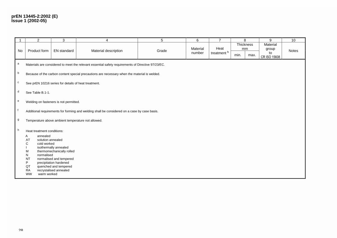
a Materials are considered to meet the relevant essential safety requirements of Directive 97/23/EC.
b Because of the carbon content special precautions are necessary when the material is welded.
c See prEN 10216 series for details of heat treatment.
d See Table B.1-1.
e Welding on fasteners is not permitted.
f Additional requirements for forming and welding shall be considered on a case by case basis.
g Temperature above ambient temperature not allowed.
h Heat treatment conditions:
A annealedAT solution annealedC cold workedI isothermally annealedM thermomechanically rolledN normalisedNT normalised and temperedP precipitation hardenedQT quenched and temperedRA recrystalised annealedWW warm worked
prEN 13445-2:2002 (E)Issue 1 (2002-05)
29
Annex B (normative)
Requirements for prevention of brittle fracture
B.1 General
This annex specifies three alternative methods for establishing criteria for the avoidance of low temperature brittlefracture1) of metallic materials in the form of plate, strip, tubes, fittings, forgings, castings, flanges, valve bodies,fasteners and weldments used in pressure parts. The criteria are based on impact energy requirements at specifiedtemperatures for the base material, heat affected zone (including the fusion line) and weld metals.
The three methods are:
Method 1 Technical requirements developed from operating experience and applicable to all metallic materials,but limited to certain thicknesses for which experience exist (see Table B.1-1).
Method 2 Technical requirements developed from the principle of fracture mechanics and from operatingexperiences but only applicable to C, CMn and low alloy ferritic steels with a specified minimum yieldstrength � 460 N/mm2. It can be applied to a wider range of thicknesses than method 1 and is lessrestrictive than method 1 for thinner materials (see Figures B.4-1 to B.4-5).
Method 3 The application of a fracture mechanics analysis. This general route is applicable to cases notcovered by methods 1 or 2. This route may also be used to justify deviations from the requirementsof method 1 and method 2. Only general guidance is given on the use of this method which shall onlybe used in agreement with the parties concerned.
Each of the three methods may be used independently. It is only necessary to satisfy the requirement of any onemethod.
B.2 Material selection and impact energy requirements
B.2.1 General
The methods specified in B.2.2, B.2.3 or B.2.4 shall be used to determine the resistance to impact energy requiredto avoid brittle fracture. The method used shall be fully documented, in order to ensure that compliance can beverified.
B.2.2 Method 1 — Code of practice
B.2.2.1 General
The impact energy requirements for the material given in Table A.2-1 shall be in accordance with Table B.1-1 andB.1-2. The impact energy requirements KV shall be met in the base material, heat affected zone (HAZ) andweldment at the material impact test temperature TKV.
1) Including temperatures at pressure tests.
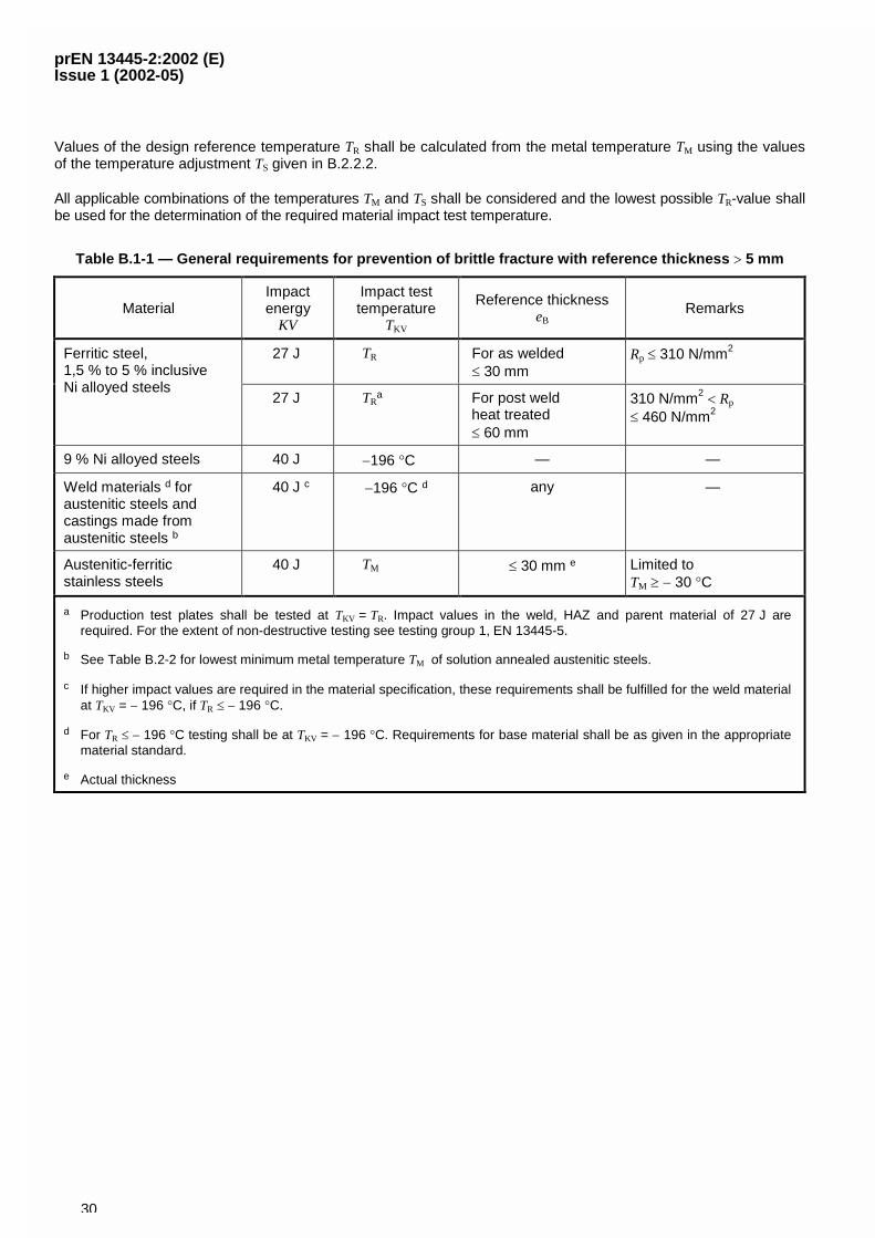
prEN 13445-2:2002 (E)Issue 1 (2002-05)
30
Values of the design reference temperature TR shall be calculated from the metal temperature TM using the valuesof the temperature adjustment TS given in B.2.2.2.
All applicable combinations of the temperatures TM and TS shall be considered and the lowest possible TR-value shallbe used for the determination of the required material impact test temperature.
Table B.1-1 — General requirements for prevention of brittle fracture with reference thickness � 5 mm
MaterialImpactenergy
KV
Impact testtemperature
TKV
Reference thicknesseB
Remarks
27 J TR For as welded� 30 mm
Rp � 310 N/mm2Ferritic steel,1,5 % to 5 % inclusiveNi alloyed steels
27 J TRa For post weld
heat treated� 60 mm
310 N/mm2 � Rp
� 460 N/mm2
9 % Ni alloyed steels 40 J �196 �C — —
Weld materials d foraustenitic steels andcastings made fromaustenitic steels b
40 J c �196 �C d any —
Austenitic-ferriticstainless steels
40 J TM � 30 mm e Limited toTM � � 30 �C
a Production test plates shall be tested at TKV = TR. Impact values in the weld, HAZ and parent material of 27 J arerequired. For the extent of non-destructive testing see testing group 1, EN 13445-5.
b See Table B.2-2 for lowest minimum metal temperature TM of solution annealed austenitic steels.
c If higher impact values are required in the material specification, these requirements shall be fulfilled for the weld materialat TKV = � 196 �C, if TR � � 196 �C.
d For TR � � 196 �C testing shall be at TKV = � 196 �C. Requirements for base material shall be as given in the appropriatematerial standard.
e Actual thickness
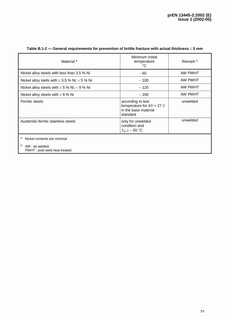
prEN 13445-2:2002 (E)Issue 1 (2002-05)
31
Table B.1-2 — General requirements for prevention of brittle fracture with actual thickness � 5 mm
Material aMinimum metal
temperature°C
Remark b
Nickel alloy steels with less than 3,5 % Ni � 60 AW PWHT
Nickel alloy stells with � 3,5 % Ni; � 5 % Ni � 100 AW PWHT
Nickel alloy steels with � 5 % Ni; � 9 % Ni � 120 AW PWHT
Nickel alloy steels with � 9 % Ni � 200 AW PWHT
Ferritic steels according to testtemperature for KV = 27 Jin the base materialstandard
unwelded
Austenitic-ferritic stainless steels only for unweldedcondition andTM � – 50 °C
unwelded
a Nickel contents are nominal
b AW : as welded,PWHT : post weld heat treated
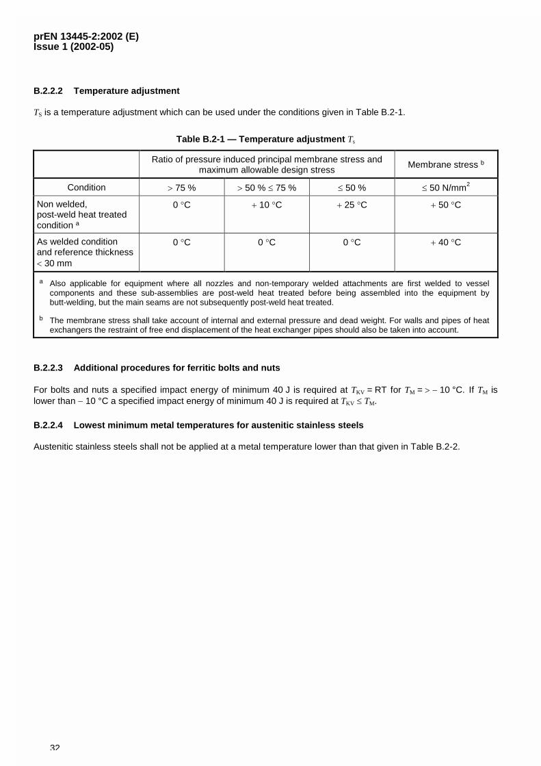
prEN 13445-2:2002 (E)Issue 1 (2002-05)
32
B.2.2.2 Temperature adjustment
TS is a temperature adjustment which can be used under the conditions given in Table B.2-1.
Table B.2-1 — Temperature adjustment Ts
Ratio of pressure induced principal membrane stress andmaximum allowable design stress
Membrane stress b
Condition � 75 % � 50 % � 75 % � 50 % � 50 N/mm2
Non welded,post-weld heat treatedcondition a
0 �C � 10 �C � 25 �C � 50 �C
As welded conditionand reference thickness� 30 mm
0 �C 0 �C 0 �C � 40 �C
a Also applicable for equipment where all nozzles and non-temporary welded attachments are first welded to vesselcomponents and these sub-assemblies are post-weld heat treated before being assembled into the equipment bybutt-welding, but the main seams are not subsequently post-weld heat treated.
b The membrane stress shall take account of internal and external pressure and dead weight. For walls and pipes of heatexchangers the restraint of free end displacement of the heat exchanger pipes should also be taken into account.
B.2.2.3 Additional procedures for ferritic bolts and nuts
For bolts and nuts a specified impact energy of minimum 40 J is required at TKV = RT for TM = � � 10 °C. If TM islower than � 10 °C a specified impact energy of minimum 40 J is required at TKV � TM.
B.2.2.4 Lowest minimum metal temperatures for austenitic stainless steels
Austenitic stainless steels shall not be applied at a metal temperature lower than that given in Table B.2-2.
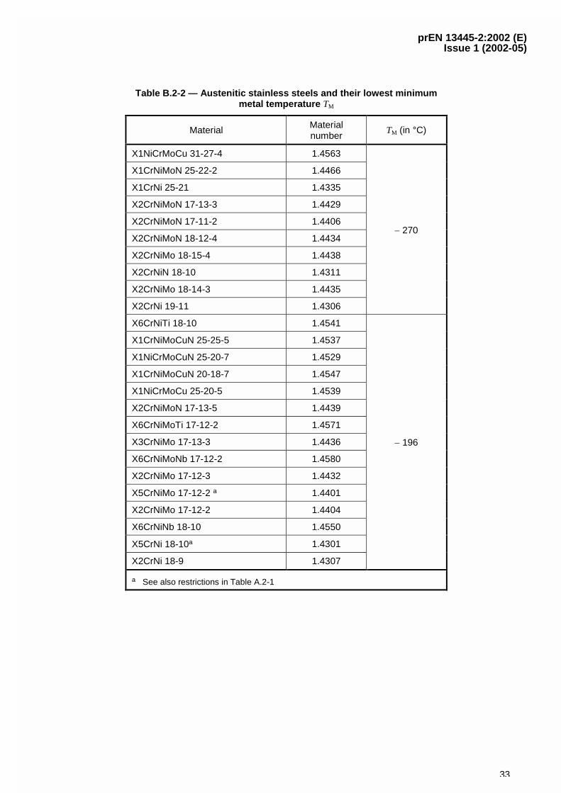
prEN 13445-2:2002 (E)Issue 1 (2002-05)
33
Table B.2-2 — Austenitic stainless steels and their lowest minimummetal temperature TM
Material Materialnumber
TM (in °C)
X1NiCrMoCu 31-27-4 1.4563
X1CrNiMoN 25-22-2 1.4466
X1CrNi 25-21 1.4335
X2CrNiMoN 17-13-3 1.4429
X2CrNiMoN 17-11-2 1.4406
X2CrNiMoN 18-12-4 1.4434
X2CrNiMo 18-15-4 1.4438
X2CrNiN 18-10 1.4311
X2CrNiMo 18-14-3 1.4435
X2CrNi 19-11 1.4306
� 270
X6CrNiTi 18-10 1.4541
X1CrNiMoCuN 25-25-5 1.4537
X1NiCrMoCuN 25-20-7 1.4529
X1CrNiMoCuN 20-18-7 1.4547
X1NiCrMoCu 25-20-5 1.4539
X2CrNiMoN 17-13-5 1.4439
X6CrNiMoTi 17-12-2 1.4571
X3CrNiMo 17-13-3 1.4436
X6CrNiMoNb 17-12-2 1.4580
X2CrNiMo 17-12-3 1.4432
X5CrNiMo 17-12-2 a 1.4401
X2CrNiMo 17-12-2 1.4404
X6CrNiNb 18-10 1.4550
X5CrNi 18-10a 1.4301
X2CrNi 18-9 1.4307
� 196
a See also restrictions in Table A.2-1
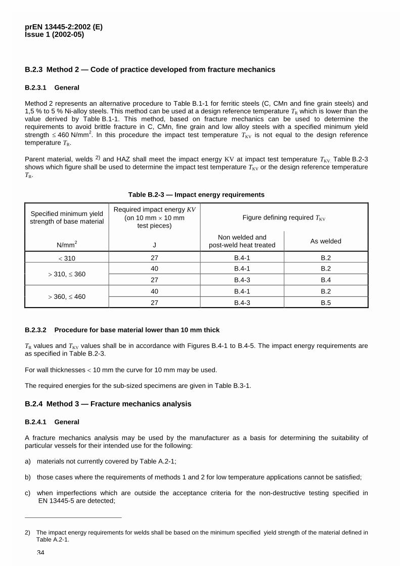
prEN 13445-2:2002 (E)Issue 1 (2002-05)
34
B.2.3 Method 2 — Code of practice developed from fracture mechanics
B.2.3.1 General
Method 2 represents an alternative procedure to Table B.1-1 for ferritic steels (C, CMn and fine grain steels) and1,5 % to 5 % Ni-alloy steels. This method can be used at a design reference temperature TR which is lower than thevalue derived by Table B.1-1. This method, based on fracture mechanics can be used to determine therequirements to avoid brittle fracture in C, CMn, fine grain and low alloy steels with a specified minimum yieldstrength � 460 N/mm2. In this procedure the impact test temperature TKV is not equal to the design referencetemperature TR.
Parent material, welds 2) and HAZ shall meet the impact energy KV at impact test temperature TKV . Table B.2-3shows which figure shall be used to determine the impact test temperature TKV or the design reference temperatureTR.
Table B.2-3 — Impact energy requirements
Specified minimum yieldstrength of base material
Required impact energy KV(on 10 mm � 10 mm
test pieces)Figure defining required TKV
N/mm2 JNon welded and
post-weld heat treatedAs welded
� 310 27 B.4-1 B.2
40 B.4-1 B.2� 310, � 360
27 B.4-3 B.4
40 B.4-1 B.2� 360, � 460
27 B.4-3 B.5
B.2.3.2 Procedure for base material lower than 10 mm thick
TR values and TKV values shall be in accordance with Figures B.4-1 to B.4-5. The impact energy requirements areas specified in Table B.2-3.
For wall thicknesses � 10 mm the curve for 10 mm may be used.
The required energies for the sub-sized specimens are given in Table B.3-1.
B.2.4 Method 3 — Fracture mechanics analysis
B.2.4.1 General
A fracture mechanics analysis may be used by the manufacturer as a basis for determining the suitability ofparticular vessels for their intended use for the following:
a) materials not currently covered by Table A.2-1;
b) those cases where the requirements of methods 1 and 2 for low temperature applications cannot be satisfied;
c) when imperfections which are outside the acceptance criteria for the non-destructive testing specified inEN 13445-5 are detected;
2) The impact energy requirements for welds shall be based on the minimum specified yield strength of the material defined inTable A.2-1.
prEN 13445-2:2002 (E)Issue 1 (2002-05)
35
d) where it is proposed to use materials in thickness greater than permitted by the low temperature requirements.
NOTE Guidance on fracture mechanics analysis is given in publications [5] to [10] listed in the bibliography.
Such analyses shall be undertaken in accordance with the requirements of B.2.4.2 to B.2.4.5.
B.2.4.2 Fracture toughness properties shall be obtained in accordance with fracture toughness testing proce-dures using full-thickness single-edge notched-bend specimens or equivalent compact tension tests with fatiguecracks located through thickness in the weld centre-line and in parent material. Further test sampling of heataffected zone regions shall also be specified, particularly when fatigue or some other in-service crack growthmechanism may be significant.
When HAZ tests are specified special considerations are necessary with regard to the placement of the notch andmetallurgical sectioning subsequent to testing.
B.2.4.3 For material not covered by the low temperature requirements of methods 1 or 2, a similar level oftolerance to fracture can be obtained by specifying fracture toughness requirements determined from the use ofassessment procedures such as in [9] with a reference defect size as determined by the manufacturer (e.g. athrough wall flaw of total length equal to 10 mm, or a quarter wall thickness surface flaw with length six times itsdepth) and inputs of an equivalent stress (or strain) relating to the hydraulic test condition, for a defect in a region ofstress concentration and subject to residual stresses equivalent to the room temperature yield strength of the basematerial for as welded components, or 30 % of yield for post weld heat treated components.
B.2.4.4 If non-destructive testing methods are employed which allow accurate sizing of defects, these values,together with information on the stress state of the critical regions in the vessel, shall be used with appropriatefracture assessment procedures to specify more accurate toughness requirements than those specified bymethod 1 or 2.
B.2.4.5 For materials which are covered by the low temperature requirements for method 1 or 2, but where theCharpy impact energy requirements cannot be met, a fitness-for-purpose assessment using representative fracturetoughness data and inspection requirements may be employed to determine the integrity of the vessel for itsintended use.
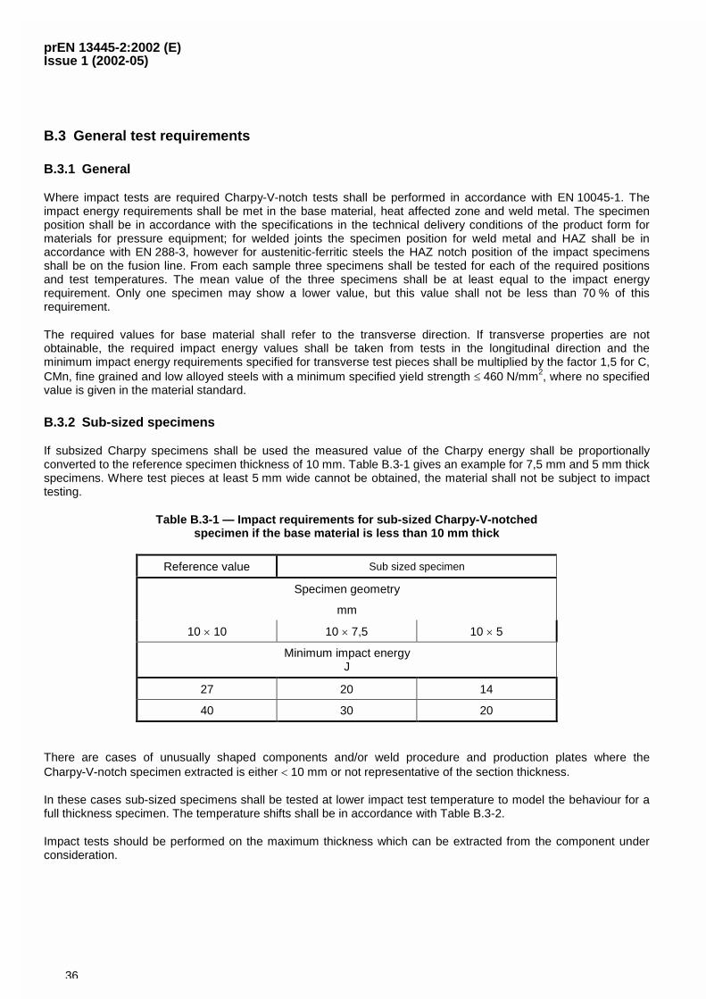
prEN 13445-2:2002 (E)Issue 1 (2002-05)
36
B.3 General test requirements
B.3.1 General
Where impact tests are required Charpy-V-notch tests shall be performed in accordance with EN 10045-1. Theimpact energy requirements shall be met in the base material, heat affected zone and weld metal. The specimenposition shall be in accordance with the specifications in the technical delivery conditions of the product form formaterials for pressure equipment; for welded joints the specimen position for weld metal and HAZ shall be inaccordance with EN 288-3, however for austenitic-ferritic steels the HAZ notch position of the impact specimensshall be on the fusion line. From each sample three specimens shall be tested for each of the required positionsand test temperatures. The mean value of the three specimens shall be at least equal to the impact energyrequirement. Only one specimen may show a lower value, but this value shall not be less than 70 % of thisrequirement.
The required values for base material shall refer to the transverse direction. If transverse properties are notobtainable, the required impact energy values shall be taken from tests in the longitudinal direction and theminimum impact energy requirements specified for transverse test pieces shall be multiplied by the factor 1,5 for C,CMn, fine grained and low alloyed steels with a minimum specified yield strength � 460 N/mm2, where no specifiedvalue is given in the material standard.
B.3.2 Sub-sized specimens
If subsized Charpy specimens shall be used the measured value of the Charpy energy shall be proportionallyconverted to the reference specimen thickness of 10 mm. Table B.3-1 gives an example for 7,5 mm and 5 mm thickspecimens. Where test pieces at least 5 mm wide cannot be obtained, the material shall not be subject to impacttesting.
Table B.3-1 — Impact requirements for sub-sized Charpy-V-notchedspecimen if the base material is less than 10 mm thick
Reference value Sub sized specimen
Specimen geometry
mm
10 � 10 10 � 7,5 10 � 5
Minimum impact energyJ
27 20 14
40 30 20
There are cases of unusually shaped components and/or weld procedure and production plates where theCharpy-V-notch specimen extracted is either � 10 mm or not representative of the section thickness.
In these cases sub-sized specimens shall be tested at lower impact test temperature to model the behaviour for afull thickness specimen. The temperature shifts shall be in accordance with Table B.3-2.
Impact tests should be performed on the maximum thickness which can be extracted from the component underconsideration.
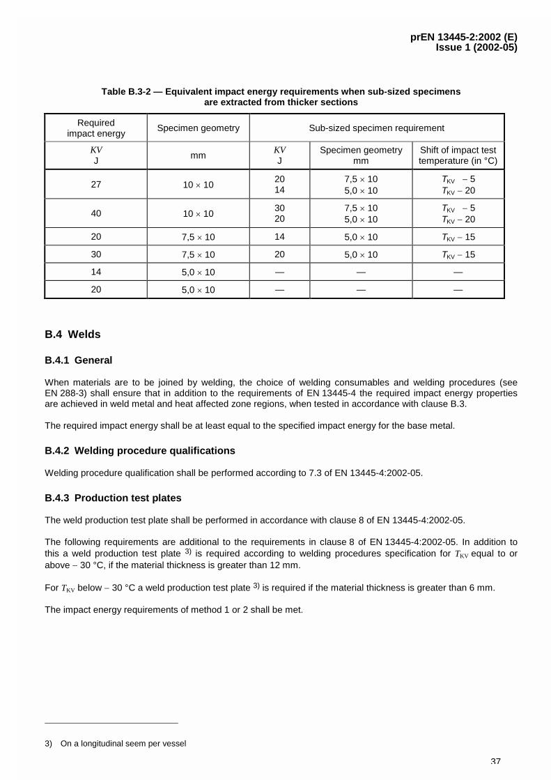
prEN 13445-2:2002 (E)Issue 1 (2002-05)
37
Table B.3-2 — Equivalent impact energy requirements when sub-sized specimensare extracted from thicker sections
Requiredimpact energy
Specimen geometry Sub-sized specimen requirement
KVJ
mmKVJ
Specimen geometrymm
Shift of impact testtemperature (in °C)
27 10 � 102014
7,5 � 105,0 � 10
TKV � 5TKV � 20
40 10 � 103020
7,5 � 105,0 � 10
TKV � 5TKV � 20
20 7,5 � 10 14 5,0 � 10 TKV � 15
30 7,5 � 10 20 5,0 � 10 TKV � 15
14 5,0 � 10 — — —
20 5,0 � 10 — — —
B.4 Welds
B.4.1 General
When materials are to be joined by welding, the choice of welding consumables and welding procedures (seeEN 288-3) shall ensure that in addition to the requirements of EN 13445-4 the required impact energy propertiesare achieved in weld metal and heat affected zone regions, when tested in accordance with clause B.3.
The required impact energy shall be at least equal to the specified impact energy for the base metal.
B.4.2 Welding procedure qualifications
Welding procedure qualification shall be performed according to 7.3 of EN 13445-4:2002-05.
B.4.3 Production test plates
The weld production test plate shall be performed in accordance with clause 8 of EN 13445-4:2002-05.
The following requirements are additional to the requirements in clause 8 of EN 13445-4:2002-05. In addition tothis a weld production test plate 3) is required according to welding procedures specification for TKV equal to orabove � 30 °C, if the material thickness is greater than 12 mm.
For TKV below � 30 °C a weld production test plate 3) is required if the material thickness is greater than 6 mm.
The impact energy requirements of method 1 or 2 shall be met.
3) On a longitudinal seem per vessel
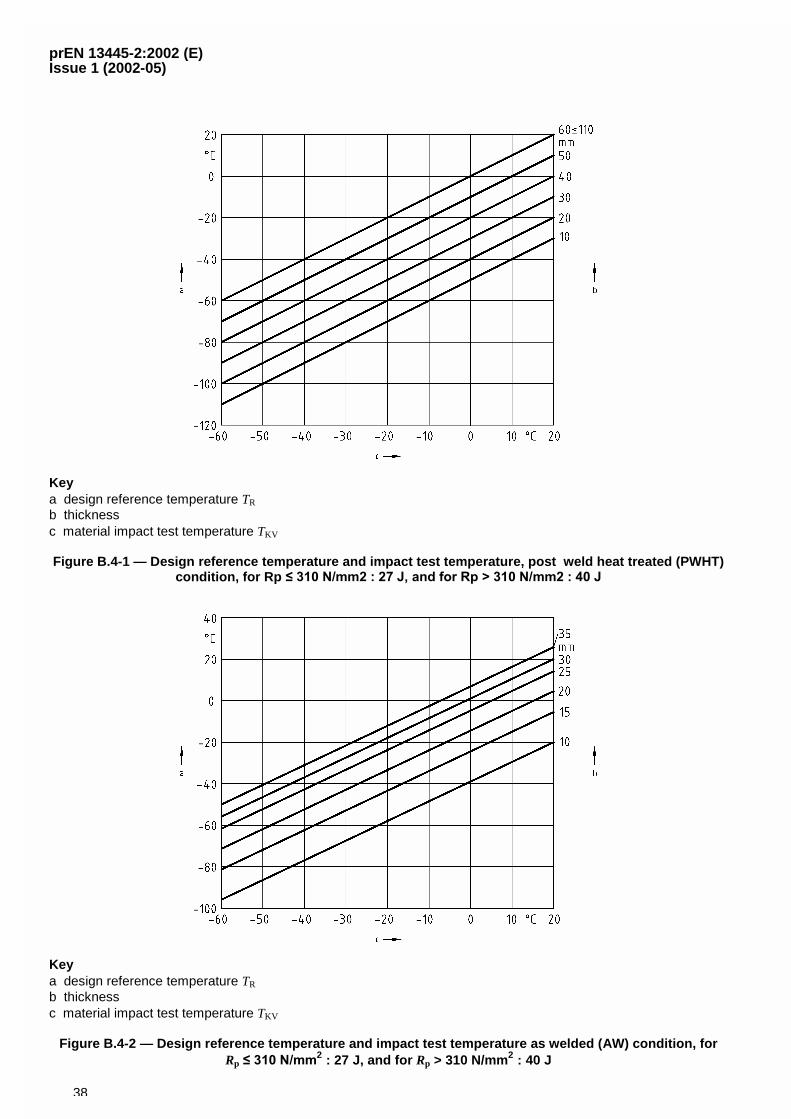
prEN 13445-2:2002 (E)Issue 1 (2002-05)
38
Keya design reference temperature TR
b thicknessc material impact test temperature TKV
Figure B.4-1 — Design reference temperature and impact test temperature, post weld heat treated (PWHT)condition, for Rp ��������������� ����������������������������
Keya design reference temperature TR
b thicknessc material impact test temperature TKV
Figure B.4-2 — Design reference temperature and impact test temperature as welded (AW) condition, forRp ����������
2 : 27 J, and for Rp > 310 N/mm2 : 40 J
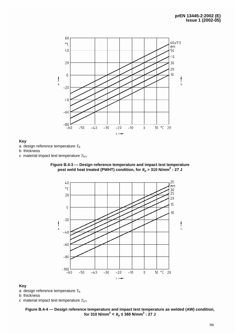
prEN 13445-2:2002 (E)Issue 1 (2002-05)
39
Keya design reference temperature TR
b thicknessc material impact test temperature TKV
Figure B.4-3 — Design reference temperature and impact test temperaturepost weld heat treated (PWHT) condition, for Rp > 310 N/mm2 : 27 J
Keya design reference temperature TR
b thicknessc material impact test temperature TKV
Figure B.4-4 — Design reference temperature and impact test temperature as welded (AW) condition,for 310 N/mm 2 < Rp ����������
2 : 27 J
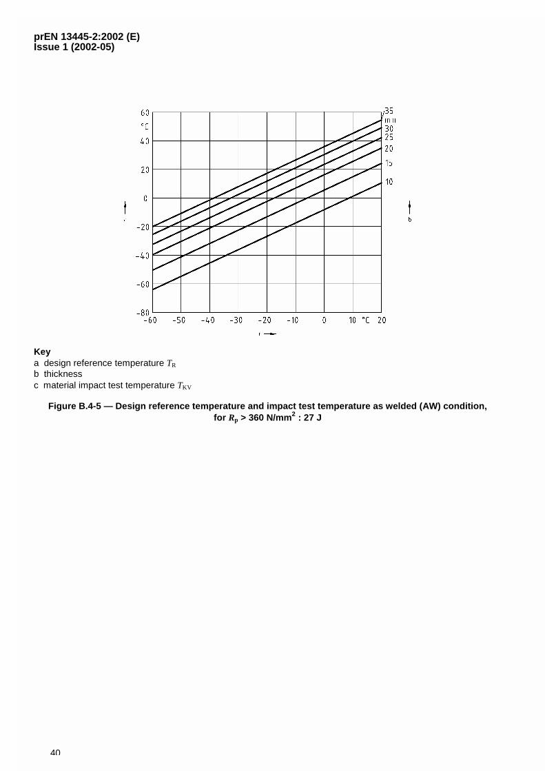
prEN 13445-2:2002 (E)Issue 1 (2002-05)
40
Keya design reference temperature TR
b thicknessc material impact test temperature TKV
Figure B.4-5 — Design reference temperature and impact test temperature as welded (AW) condition,for Rp > 360 N/mm2 : 27 J
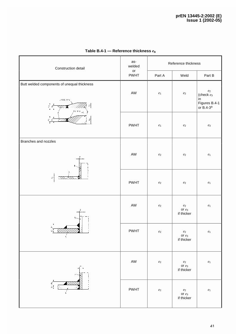
prEN 13445-2:2002 (E)Issue 1 (2002-05)
41
Table B.4-1 — Reference thickness eB
Reference thicknessConstruction detail
as-welded
orPWHT Part A Weld Part B
Butt welded components of unequal thickness
AW e1 e2e2
(check e3
inFigures B.4-1or B.4-3a
PWHT e1 e2 e3
Branches and nozzles
AW e2 e2 e1
PWHT e2 e2 e1
AW e2 e2
or e3
if thicker
e1
PWHT e2 e2
or e3
if thicker
e1
AW e2 e2
or e3
if thicker
e1
PWHT e2 e2
or e3
if thicker
e1
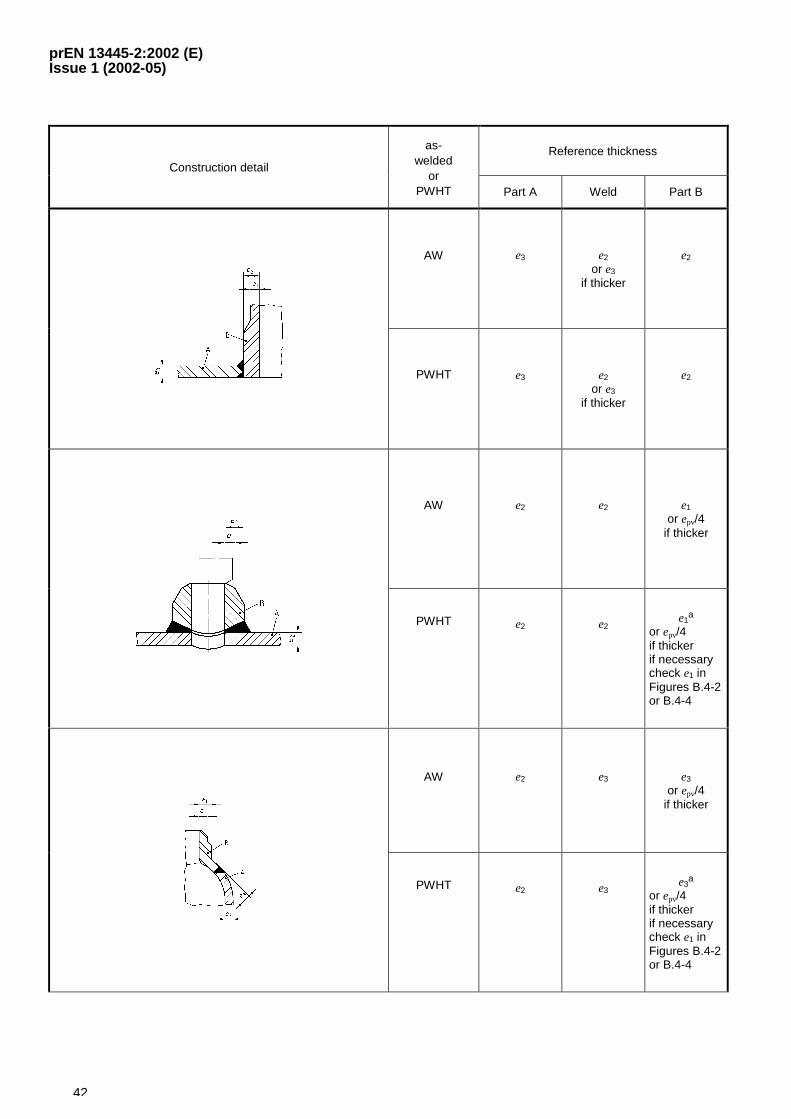
prEN 13445-2:2002 (E)Issue 1 (2002-05)
42
Reference thicknessConstruction detail
as-welded
orPWHT Part A Weld Part B
AW e3 e2
or e3
if thicker
e2
PWHT e3 e2
or e3
if thicker
e2
AW e2 e2 e1
or epv/4if thicker
PWHT e2 e2e1
a
or epv/4if thickerif necessarycheck e1 inFigures B.4-2or B.4-4
AW e2 e3 e3
or epv/4if thicker
PWHT e2 e3e3
a
or epv/4if thickerif necessarycheck e1 inFigures B.4-2or B.4-4
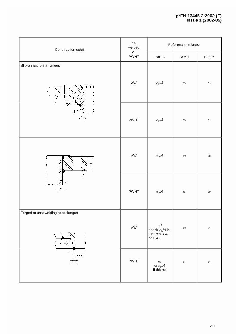
prEN 13445-2:2002 (E)Issue 1 (2002-05)
43
Reference thicknessConstruction detail
as-welded
orPWHT Part A Weld Part B
Slip-on and plate flanges
AW epv/4 e2 e2
PWHT epv/4 e2 e2
AW epv/4 e2 e2
PWHT epv/4 e2 e2
Forged or cast welding neck flanges
AW e2a
check epv/4 inFigures B.4-1or B.4-3
e2 e1
PWHT e2
or epv/4if thicker
e2 e1
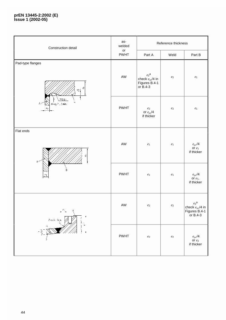
prEN 13445-2:2002 (E)Issue 1 (2002-05)
44
Reference thicknessConstruction detail
as-welded
orPWHT Part A Weld Part B
Pad-type flanges
AW e2a
check epv/4 inFigures B.4-1or B.4-3
e2 e1
PWHT e2
or epv/4if thicker
e2 e1
Flat ends
AW e1 e1 epv'/4or e1
if thicker
PWHT e1 e1 epv'/4or e1,
if thicker
AW e2 e2e2
a
check epv'/4 inFigures B.4-1
or B.4-3
PWHT e2 e2 epv'/4or e2
if thicker
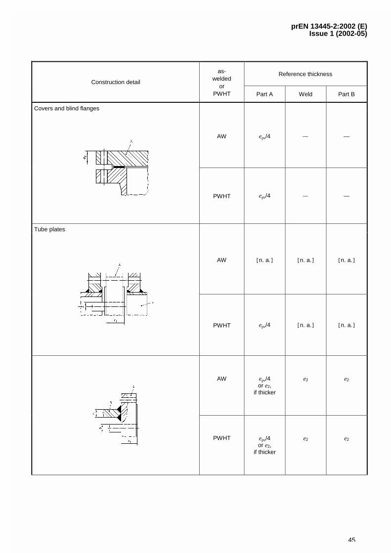
prEN 13445-2:2002 (E)Issue 1 (2002-05)
45
Reference thicknessConstruction detail
as-welded
orPWHT Part A Weld Part B
Covers and blind flanges
AW epv/4 — —
PWHT epv/4 — —
Tube plates
AW �n. a.� �n. a.� �n. a.�
PWHT epv/4 �n. a.� �n. a.�
AW epv/4or e2,
if thicker
e2 e2
PWHT epv/4or e2,
if thicker
e2 e2
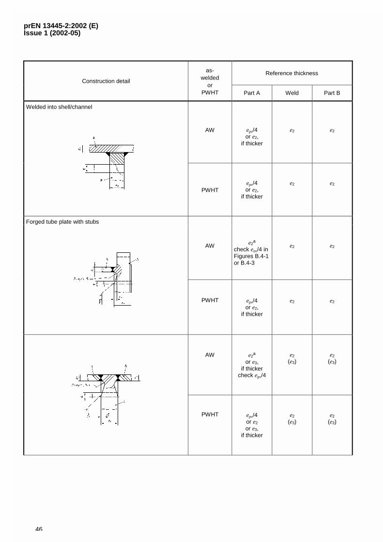
prEN 13445-2:2002 (E)Issue 1 (2002-05)
46
Reference thicknessConstruction detail
as-welded
orPWHT Part A Weld Part B
Welded into shell/channel
AW epv/4or e2,
if thicker
e2 e2
PWHTepv/4or e2,
if thicker
e2 e2
Forged tube plate with stubs
AW e2a
check epv/4 inFigures B.4-1or B.4-3
e2 e2
PWHT epv/4or e2,
if thicker
e2 e2
AW e2a
or e3,if thicker
check epv/4
e2
(e3)e2
(e3)
PWHT epv/4or e2
or e3,if thicker
e2
(e3)e2
(e3)
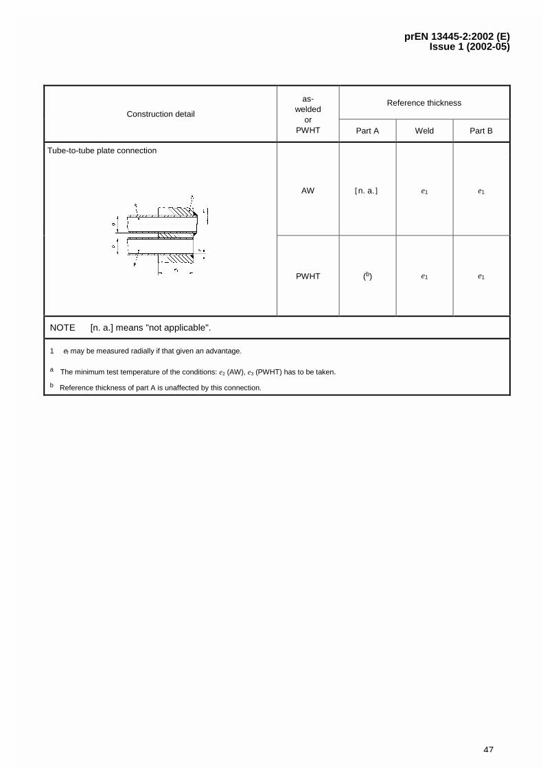
prEN 13445-2:2002 (E)Issue 1 (2002-05)
47
Reference thicknessConstruction detail
as-welded
orPWHT Part A Weld Part B
Tube-to-tube plate connection
AW �n. a.� e1 e1
PWHT (b) e1 e1
NOTE [n. a.] means "not applicable".
1 ef may be measured radially if that given an advantage.
a The minimum test temperature of the conditions: e2 (AW), e3 (PWHT) has to be taken.
b Reference thickness of part A is unaffected by this connection.
prEN 13445-2:2002 (E)Issue 1 (2002-05)
48
Annex C (informative)
Technical delivery conditions for clad products for pressure purposes
C.1 Introductory note
Until a European Standard for clad steel products for pressure purposes is available, the requirements for thetechnical delivery conditions of such products shall form the basis for an agreement of the parties involved.
C.2 Requirements for the material
For the material of clad products the relevant conditions of EN 13445-2 shall apply.
In addition, where appropriate, requirements for impact tests of the kind described in clause C.4, item b, shall beagreed at the time of enquiry and order.
C.3 Requirements for the deposited material
Clad steels shall comply with the following general regulations:
In the case of clad steels where the cladding has a lower degree of elasticity than that of the base metal, a tensiletest on the cladding after the base has been removed should show an elongation after fracture A5 of at least 12 %.
The bond between the base and the cladding materials shall be of such a nature that there is no delaminationeither in the course of manufacture or in service. Unless otherwise stipulated in the order, the shear strength ofcladding with a tensile strength of less than 280 N/mm2 shall be more than half the minimum tensile strength of thecladding material and, for all other cladding materials, shall not be less than 140 N/mm2, regardless of the directionof testing.
The bonded area shall cover at least 95 % of the entire surface and no single unbonded area shall cover more than50 cm2. In the case of clad steels which are highly stressed during manufacture (e.g. dished ends) or when inservice (e.g. tube plates), additional requirements imposed by the purchaser (operator) can be necessary.
The cladding material shall have a surface texture which corresponds to the cladding process and be of uniformthickness with tolerances not exceeding those given in Table C.3-1.
The permissible tolerances for the base material are given in the relevant dimensional standards for the variousproducts.
prEN 13445-2:2002 (E)Issue 1 (2002-05)
49
Table C.3-1 — Limit deviations on thickness for cladding materialson clad steels
Nominal thicknessmm
Limit deviations on thickness a, b
mm
1,0 � 0,10
1,5 � 0,15
2,0 � 0,20
2,5 � 0,25
3,0 � 0,35
3,5 � 0,45
4,0 � 0,50
4,5 � 0,50
� 5,0 � 0,50
a Deviations from the values in this table are subject to special agreement.
b For intermediate thicknesses the Limit deviation indicated for the next smallestthickness in the table applies.
C.4 Qualification of the cladding procedure
Before commencing production, suitable cladding conditions shall be verified by cladding procedure qualificationtests, including welding procedure tests for weld overlay, if applicable. These conditions shall be carefully observedwhen cladding the products in the plant.
The cladding procedure qualification tests shall normally comprise:
e) tensile tests in accordance with EN 10002-1;
f) Charpy-V-notch impact tests in accordance with EN 10045-1 at the temperature specified for test pieces takenfrom the cladded base material so that
one side of the test piece coincides with the bonded area between the base and deposited material;
the longitudinal direction of the test piece is transverse to the direction of rolling; and
the axis of the notch is perpendicular to the next surface of the base material (see Figure C.5-1, item d);
g) bend tests on test pieces which, as shown in Figure C.5-2 cover the bonded zone and are bent in a directionparallel to the bounding zone;
h) the examination of the hardness, micro- and macrostructure and chemical composition in the transition zone;
i) shear tests on shear specimens;
j) inspection of surface quality and conformity to dimensions;
k) ultrasonic testing of the bond between the base material and the cladding.
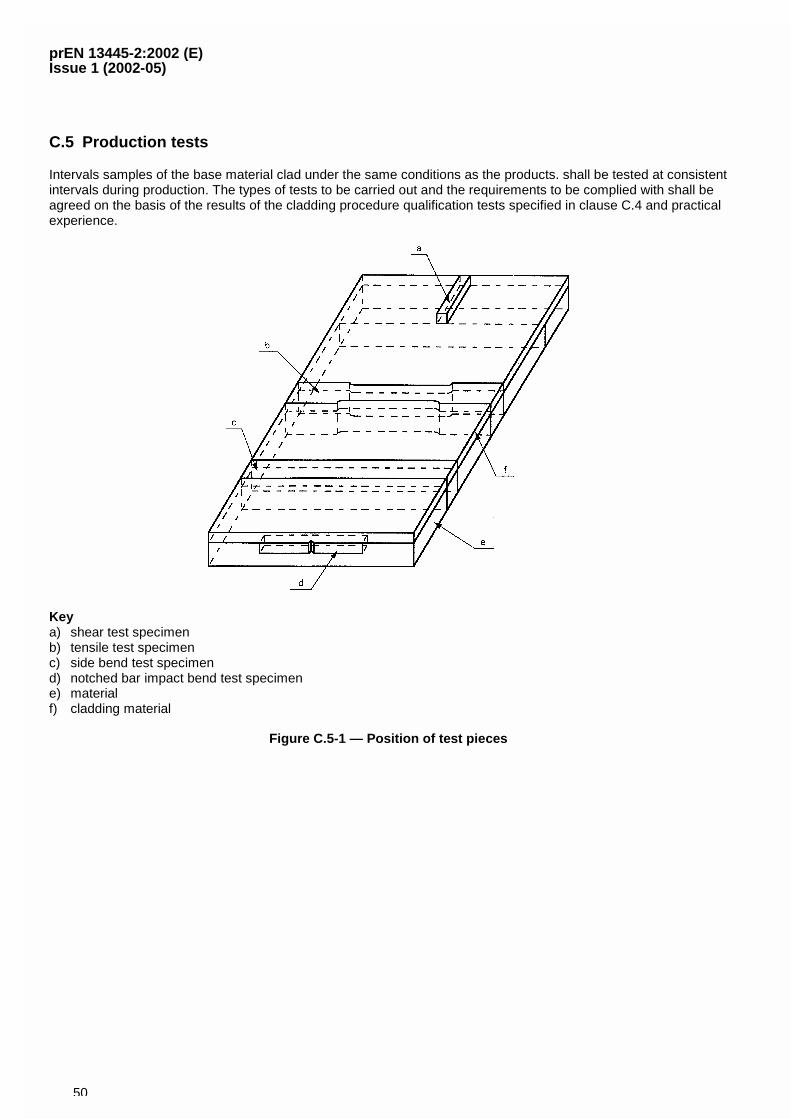
prEN 13445-2:2002 (E)Issue 1 (2002-05)
50
C.5 Production tests
Intervals samples of the base material clad under the same conditions as the products. shall be tested at consistentintervals during production. The types of tests to be carried out and the requirements to be complied with shall beagreed on the basis of the results of the cladding procedure qualification tests specified in clause C.4 and practicalexperience.
Keya) shear test specimenb) tensile test specimenc) side bend test specimend) notched bar impact bend test specimene) materialf) cladding material
Figure C.5-1 — Position of test pieces
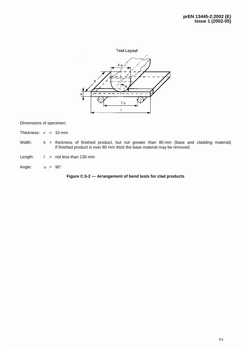
prEN 13445-2:2002 (E)Issue 1 (2002-05)
51
Dimensions of specimen:
Thickness: e = 10 mm
Width: b = thickness of finished product, but not greater than 80 mm (base and cladding material)If finished product is over 80 mm thick the base material may be removed.
Length: l = not less than 130 mm
Angle: � = 90�
Figure C.5-2 — Arrangement of bend tests for clad products
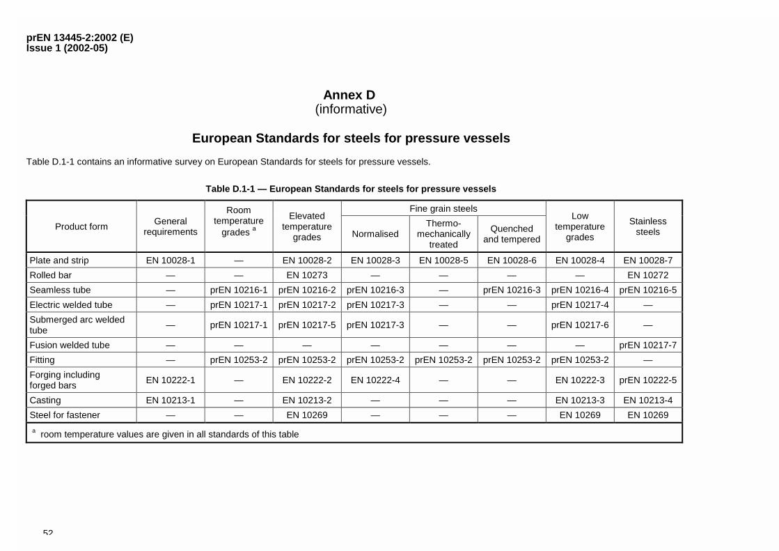
prEN 13445-2:2002 (E)Issue 1 (2002-05)
52
Annex D (informative)
European Standards for steels for pressure vessels
Table D.1-1 contains an informative survey on European Standards for steels for pressure vessels.
Table D.1-1 — European Standards for steels for pressure vessels
Fine grain steels
Product formGeneral
requirements
Roomtemperature
grades aElevated
temperaturegrades Normalised
Thermo-mechanically
treated
Quenchedand tempered
Lowtemperature
grades
Stainlesssteels
Plate and strip EN 10028-1 — EN 10028-2 EN 10028-3 EN 10028-5 EN 10028-6 EN 10028-4 EN 10028-7
Rolled bar — — EN 10273 — — — — EN 10272
Seamless tube — prEN 10216-1 prEN 10216-2 prEN 10216-3 — prEN 10216-3 prEN 10216-4 prEN 10216-5
Electric welded tube — prEN 10217-1 prEN 10217-2 prEN 10217-3 — — prEN 10217-4 —
Submerged arc weldedtube
— prEN 10217-1 prEN 10217-5 prEN 10217-3 — — prEN 10217-6 —
Fusion welded tube — — — — — — — prEN 10217-7
Fitting — prEN 10253-2 prEN 10253-2 prEN 10253-2 prEN 10253-2 prEN 10253-2 prEN 10253-2 —
Forging includingforged bars EN 10222-1 — EN 10222-2 EN 10222-4 — — EN 10222-3 prEN 10222-5
Casting EN 10213-1 — EN 10213-2 — — — EN 10213-3 EN 10213-4
Steel for fastener — — EN 10269 — — — EN 10269 EN 10269
a room temperature values are given in all standards of this table
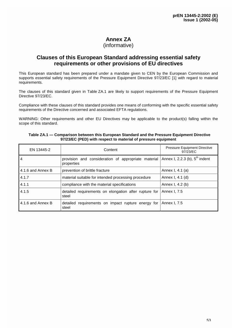
prEN 13445-2:2002 (E)Issue 1 (2002-05)
53
Annex ZA(informative)
Clauses of this European Standard addressing essential safetyrequirements or other provisions of EU directives
This European standard has been prepared under a mandate given to CEN by the European Commission andsupports essential safety requirements of the Pressure Equipment Directive 97/23/EC [1] with regard to materialrequirements.
The clauses of this standard given in Table ZA.1 are likely to support requirements of the Pressure EquipmentDirective 97/23/EC.
Compliance with these clauses of this standard provides one means of conforming with the specific essential safetyrequirements of the Directive concerned and associated EFTA regulations.
WARNING: Other requirements and other EU Directives may be applicable to the product(s) falling within thescope of this standard.
Table ZA.1 — Comparison between this European Standard and the Pressure Equipment Directive97/23/EC (PED) with respect to material of pressure equipment
EN 13445-2 Content Pressure Equipment Directive97/23/EC
4 provision and consideration of appropriate materialproperties
Annex I, 2.2.3 (b), 5th indent
4.1.6 and Annex B prevention of brittle fracture Annex I, 4.1 (a)
4.1.7 material suitable for intended processing procedure Annex I, 4.1 (d)
4.1.1 compliance with the material specifications Annex I, 4.2 (b)
4.1.5 detailed requirements on elongation after rupture forsteel
Annex I, 7.5
4.1.6 and Annex B detailed requirements on impact rupture energy forsteel
Annex I, 7.5
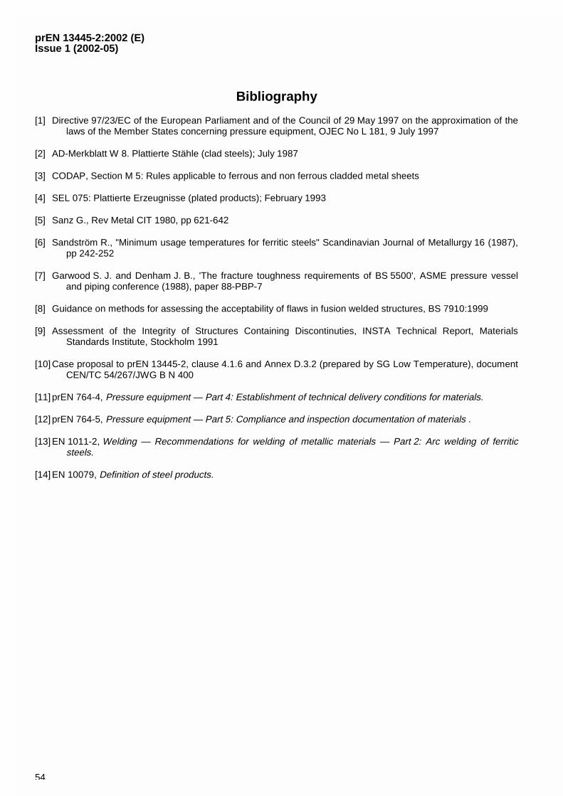
prEN 13445-2:2002 (E)Issue 1 (2002-05)
54
Bibliography
[1] Directive 97/23/EC of the European Parliament and of the Council of 29 May 1997 on the approximation of thelaws of the Member States concerning pressure equipment, OJEC No L 181, 9 July 1997
[2] AD-Merkblatt W 8. Plattierte Stähle (clad steels); July 1987
[3] CODAP, Section M 5: Rules applicable to ferrous and non ferrous cladded metal sheets
[4] SEL 075: Plattierte Erzeugnisse (plated products); February 1993
[5] Sanz G., Rev Metal CIT 1980, pp 621-642
[6] Sandström R., "Minimum usage temperatures for ferritic steels" Scandinavian Journal of Metallurgy 16 (1987),pp 242-252
[7] Garwood S. J. and Denham J. B., 'The fracture toughness requirements of BS 5500', ASME pressure vesseland piping conference (1988), paper 88-PBP-7
[8] Guidance on methods for assessing the acceptability of flaws in fusion welded structures, BS 7910:1999
[9] Assessment of the Integrity of Structures Containing Discontinuties, INSTA Technical Report, MaterialsStandards Institute, Stockholm 1991
[10] Case proposal to prEN 13445-2, clause 4.1.6 and Annex D.3.2 (prepared by SG Low Temperature), documentCEN/TC 54/267/JWG B N 400
[11] prEN 764-4, Pressure equipment — Part 4: Establishment of technical delivery conditions for materials.
[12] prEN 764-5, Pressure equipment — Part 5: Compliance and inspection documentation of materials .
[13] EN 1011-2, Welding — Recommendations for welding of metallic materials — Part 2: Arc welding of ferriticsteels.
[14] EN 10079, Definition of steel products.