sprolan 3-wat heat reclaim valves service manual
DESCRIPTION
Sporlan D5D-8D-12D and other 3-Way Heat Reclaim ValvesTRANSCRIPT

April 2007 / BULLETIN 30-21
Installation and Servicing Instructions
3-Way Valves
CONTENTSB5D, 8D, 12D & 16D 3-Way Heat Reclaim Valves . . . . . . . . . . . . . 28D-SC, 12D-SC & 16D-SC 3-Way Split Condenser Valves . . . . . . 510G79B, 10G711B & 10G711C 3-Way Hot Gas Defrost Valves . . . 6180 Solenoid Pilot Control . . . . . . . . . . . . . . . . . . . . . . . . . . . . . . . . . 8General Information. . . . . . . . . . . . . . . . . . . . . . . . . . . . . . . . . . . . . . 11Replacement Parts Kits. . . . . . . . . . . . . . . . . . . . . . . . . . . . . . . . . . . 12

Page � / Bulletin 30-21
OPERATION“B” TYPENORMAL (OUTDOOR) CONDENSER - De-energized See Figure 1. With the pilot valve de-energized, high side pressure is prevented from entering the cavity above the piston assembly. At the same time, the upper pilot port is open to suction pressure. The resulting pressure differential across the piston moves the piston-seat assembly to close the reclaim condenser port (upper main port). In this mode, the refrigerant flows to the normal con-denser. The pilot valve opens the cavity above the piston to suc-tion. This allows the reclaim condenser to be pumped out through a small bleed hole in the piston. The pump out process reduces the reclaim condenser to suction pressure. Once suction pressure is reached, the flow through the bleed hole in the piston stops. There is no high to low side bleed with continued operation in the nor-mal condenser mode. For a more efficient pump out of the reclaim condenser, a normally open solenoid valve can be added to the lowest physical location of the reclaim coil to remove liquid.
“C” TYPENORMAL (OUTDOOR) CONDENSER - De-energized With the pilot valve de-energized, high side pressure is prevented from entering cavity above the piston-seat assembly. At the same time the upper pilot port is opened to suction pressure. The result-ing pressure differential across the piston moves the piston-seat assembly to close the reclaim (upper) main port, thereby eliminat-ing high to low side bleed and the resulting capacity loss with the system in the normal condenser mode.
“B” AND “C” TYPERECLAIM (REHEAT) CONDENSER - EnergizedWhen the pilot valve is energized, high side pressure is permitted to flow through the lower pilot port at the same time the upper pilot port is closed to suction. High side pressure build up on top of the piston moves the piston-seat assembly to close the normal condenser port and open the reclaim (upper) main port. With the upper pilot port closed, there is no high to low side bleed and resulting capacity loss with the system in the reclaim mode.
Valves using the MKC-1 coil may be used on fluids or gases where the temperature does not exceed 240°F, while the valve ambient is 120°F. The coil is Underwriters Laboratory Class F rated.
TYPES B5D, 8D, 12D & 16D 3-WAY HEAT RECLAIM VALVES
Bulletin 30-21, April 2007 supersedes Bulletin 30-21, June 2001 and all prior publications. © 2007 by Sporlan Division, Parker Hannifin Corporation
Type PortSize
Connection ODF Solder
InchesA B C D E F G H J
B5D5BB5D5C 5/8 5/8 5.00 4.36 3.22 3.22 0.79 3.84 0.50 2.94
1.64
8D7B8D7C 3/4
7/85.18
5.063.44 3.44 1.13 2.63
0.75
2.89
8D9B8D9C 1-1/8 5.13 0.91
12D11B12D11C
1-1/4
1-3/8
6.87 6.94 4.19 4.19 2.38 4.25
0.97
12D13B12D13C 1-5/8 1.09
12D17B 2-1/8 1.2516D17B16D17C 2 2-1/8 8.18 9.53 5.47 5.47 3.50 5.44 1.25 3.17
NOT FOR USE WITH HAZARDOUS OR CORROSIVE FLUIDS
INSTALLATIONPIPING SUGGESTIONSValves must be installed in a horizontal or vertical position with the coil level with or above the valve body. Install Heat Reclaim Valves so the connections are in the proper flow direction as shown in Figure 2.
Figure 3, page 4, shows piping schematics only to illustrate the general installation of the Heat Reclaim Valves. Sporlan recom-mends that recognized piping references be consulted for assis-tance in piping procedures. Sporlan is not responsible for system design, any damage resulting from system design, or for misap-plication of its products.
Proper support of heat reclaim valves is essential. Concentrated stresses resulting from thermal expansion or compressor vibra-tions can cause fatigue failure of tubing, elbows and valve fittings. Fatigue failures can also result from vapor propelled liquid slug-ging, and condensation induced shock. The use of piping brackets close to each of the three way valve fittings is recommended.
Suction
ReclaimCondenser
CompressorDischarge
NormalCondenser
1/4” SAE
A
B
D C
EG
Optional 1/2” Conduit Boss
J
F
Figure 2 H
CompressorDischarge
Suction
ReclaimCondenser
Bleed Hole
Figure 1 “B” TYPERECLAIM CONDENSERPUMP OUT
DIMENSIONS – Inches
Bulletin 30-21 / Page �
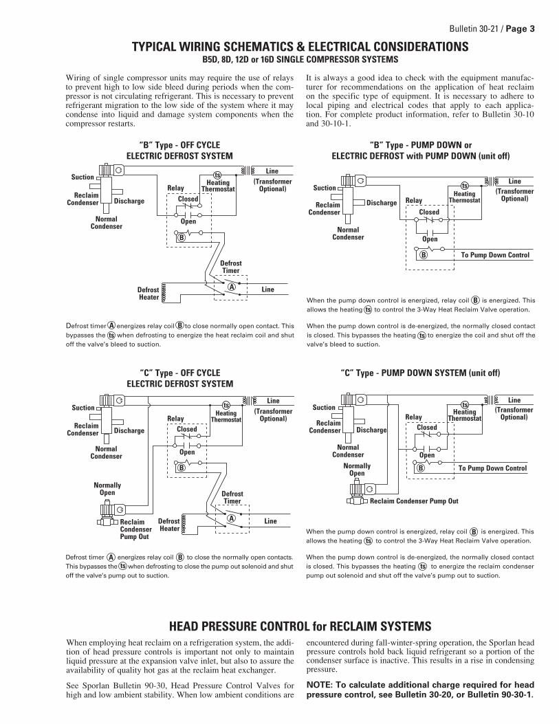
Wiring of single compressor units may require the use of relays to prevent high to low side bleed during periods when the com-pressor is not circulating refrigerant. This is necessary to prevent refrigerant migration to the low side of the system where it may condense into liquid and damage system components when the compressor restarts.
It is always a good idea to check with the equipment manufac-turer for recommendations on the application of heat reclaim on the specific type of equipment. It is necessary to adhere to local piping and electrical codes that apply to each applica-tion. For complete product information, refer to Bulletin 30-10 and 30-10-1.
TYPICAL WIRING SCHEMATICS & ELECTRICAL CONSIDERATIONS B5D, 8D, 12D or 16D SINGLE COMPRESSOR SYSTEMS
When employing heat reclaim on a refrigeration system, the addi-tion of head pressure controls is important not only to maintain liquid pressure at the expansion valve inlet, but also to assure the availability of quality hot gas at the reclaim heat exchanger.
See Sporlan Bulletin 90-30, Head Pressure Control Valves for high and low ambient stability. When low ambient conditions are
encountered during fall-winter-spring operation, the Sporlan head pressure controls hold back liquid refrigerant so a portion of the condenser surface is inactive. This results in a rise in condensing pressure.
NOTE: To calculate additional charge required for head pressure control, see Bulletin �0-�0, or Bulletin 90-�0-1.
HEAD PRESSURE CONTROL for RECLAIM SYSTEMS
“B” Type - PUMP DOWN orELECTRIC DEFROST with PUMP DOWN (unit off)
When the pump down control is energized, relay coil is energized. This allows the heating to control the 3-Way Heat Reclaim Valve operation.
When the pump down control is de-energized, the normally closed contact is closed. This bypasses the heating to energize the coil and shut off the valve’s bleed to suction.
Bts
ts
Reclaim Condenser
Suction
Normal Condenser
Discharge Relay
Closed
Open
Line
HeatingThermostat
(TransformerOptional)
To Pump Down Control
ts
B
When the pump down control is energized, relay coil is energized. This allows the heating to control the 3-Way Heat Reclaim Valve operation.
When the pump down control is de-energized, the normally closed contact is closed. This bypasses the heating to energize the reclaim condenser pump out solenoid and shut off the valve’s pump out to suction.
Bts
ts
“C” Type - PUMP DOWN SYSTEM (unit off)
Reclaim Condenser
Suction
NormalCondenser
Discharge
RelayClosed
Open
HeatingThermostat
(TransformerOptional)
To Pump Down Control
Line
Reclaim Condenser Pump Out
NormallyOpen
ts
B
ReclaimCondenser
Suction
Normal Condenser
Discharge
RelayClosed
Open
Line
Line
Defrost Timer
Defrost Heater
HeatingThermostat
(TransformerOptional)
B
ts
A
Defrost timer energizes relay coil to close normally open contact. This bypasses the when defrosting to energize the heat reclaim coil and shut off the valve’s bleed to suction.
A Bts
“B” Type - OFF CYCLEELECTRIC DEFROST SYSTEM
Reclaim Condenser
Suction
Normal Condenser
Discharge
RelayClosed
Open
Line
Line
Defrost Timer
Defrost Heater
HeatingThermostat
(TransformerOptional)
Reclaim CondenserPump Out
NormallyOpen
ts
B
A
Defrost timer energizes relay coil to close the normally open contacts. This bypasses the when defrosting to close the pump out solenoid and shut off the valve’s pump out to suction.
A Bts
“C” Type - OFF CYCLEELECTRIC DEFROST SYSTEM

Page � / Bulletin 30-21
SERVICETYPICAL MALFUNCTIONSThere are only three possible malfunctions: 1. Coil burnout. 2. Failure to shift to Reclaim Mode. 3. Failure to shift to Normal Mode. Each is discussed below:
COIL BURNOUTCoil burnouts are extremely rare unless caused by one of the following:1. Improper electrical characteristics.2. Continuous over-voltage, more than 10%.3. Under-voltage of more than 15%. This applies only if the oper-
ating conditions are such that the reduced MOPD causes stall-ing of the plunger, which results in excessive current draw.
4. Incomplete magnetic circuit due to the omission of the plunger assembly during reassembly.
5. Mechanical interference with movement of plunger which may be caused by a deformed enclosing tube.
6. Coil energized while not installed on a valve.
FAILURE TO SHIFT TO RECLAIM MODE1. Coil burnout (see coil burnout at left).2. MOPD greater than specifications.3. Restricted high pressure pilot connection.4. May not have allowed sufficient time to pump out the reclaim
coil while in the normal mode.FAILURE TO SHIFT TO NORMAL MODE1. Stray voltage holding plunger up.2. Restricted, closed service valve, or capped suction connection
on pilot.
Figure 3
TYPICAL PIPING SCHEMATICS
Use normally open solenoid valve and piping if pump out is required and “C” model Heat Reclaim Valve is used, see note 4.
This check valve required if lowest operating ambient temperature is lower than evaporator temperature.
Restrictor 2449-004 may be required to control pump out rate on inactive condenser.
Pilot suction line must be open to common suction whether or not Heat Reclaim Coil is installed at time of installation and regardless of Heat Reclaim Valve model/type.
Proper support of heat reclaim valves is essential. Concentrated stresses resulting from thermal expan-sion or compressor vibrations can cause fatigue failure of tubing, elbows and valve fittings. Fatigue failures can also result from vapor propelled liquid slugging, and condensation induced shock. The use of piping brackets close to each of the three way valve fittings is recommended.
Q
W
E
R
T
NormalCondenser
Check Valve
3-Way Heat Reclaim Valve Reclaim
Condenser
A8 Pressure Regulating Valve
A9 Hot Gas Bypass Regulator
(optional)Normally Open Solenoid Valve (XPM)
Receiver
Compressor
SERIES CONDENSERS
Q
T
R
E
For a list of replacement part kits, see table on page 12.
NormalCondenser
ReclaimCondenser
3-Way HeatReclaim Valve – CV
Receiver
(optional)Normally Open Solenoid Valve (XPM)
Compressor
Q
E
RT
SERIES CONDENSERS
A8 Pressure Regulating Valve
A9 Hot Gas Bypass Regulator
NormalCondenser
Check Valve
3-Way Heat Reclaim Valve
ReclaimCondenser
Check Valve
to suction
PARALLEL CONDENSERS
T
E
QR
E
W
(optional)Normally Open Solenoid Valve (XPM)
Check Valve
A8 Pressure Regulating Valve
A9 Hot Gas Bypass Regulator
Normally ClosedSolenoid Valve
Receiver
Compressor

Bulletin 30-21 / Page �
TYPES 8D-SC, 12D-SC & 16D-SC 3-WAY SPLIT CONDENSER VALVES
The Split Condenser Valves are a relatively simple modification of the standard Heat Reclaim Valves. Figure 7 shows that the Split Condenser Valves only use the upper port; the lower port is always open. The location of the seat disc has been optimized such that when the valve is in the two condenser mode, the flow is split evenly between the two condensers.
The pilot valve is different from the standard heat reclaim valve. It is normally open to high pressure.
OPERATION“B” and “C” TYPETWO CONDENSER MODE - De-energized See Figure 4. With the pilot valve de-energized, high side pressure 1 is permitted to flow through the lower pilot port at the same time the upper pilot port is closed to suction 2. High side pressure 1 built on top of the piston moves the piston-seat assembly down to evenly split the flow between the two condensers. The piston-seat assembly is held in place by a plate located in the Condenser A connection. This plate is designed to limit restriction through that port. With the upper pilot port closed, there is no high to low side bleed and no resulting capacity loss with the system in the two condenser mode.
Valves using the MKC-1 coil may be used on fluids or gases where the temperature does not exceed 240°F, while the valve ambient is 120°F. The coil is Underwriters Laboratory Class F rated.
NOTE: If the pressure in your idle Condenser B is less than the suction pressure that the suction connection of the valve is con-nected to, you may have charge migration back into your idle Condenser B. A small check valve in the suction pilot line can be used to prevent this.
“B” (Bleed) TYPESINGLE CONDENSER MODE - EnergizedSee Figure 5. With the pilot valve energized, high side pressure 1 is prevented from entering the cavity above the piston-seat assem-bly. At the same time the upper pilot port is opened to suction pressure 2. This opens the cavity above the piston-seat assembly to suction pressure 2. The cavity below the piston is exposed to high pressure. The resulting pressure differential across the piston moves the piston-seat assembly up to close the upper (Condenser B) port. We use a solid piston ring on the piston, thereby elimi-nating high to low side bleed around the piston. When the upper pilot port opens, Condenser B is pumped out through a small bleed hole in the piston. When Condenser B has been pumped out and reduced to suction pressure, all flow ceases, thus eliminating high to low side bleed and the resulting capacity loss that may occur with the system in the single condenser mode.
“C” (No Bleed) TYPESINGLE CONDENSER MODE - EnergizedSee Figure 5. With the pilot valve energized, high side pressure 1 is prevented from entering the cavity above the piston-seat assembly. At the same time the upper pilot port is opened to suction pressure 2. This opens the cavity above the piston-seat assembly to suction pressure 2. The cavity below the piston is exposed to high pressure. The resulting pressure differential across the piston moves the piston-seat assembly up to close the upper (Condenser B) port. We use a solid piston ring on the piston thereby eliminating high to
low side bleed around the piston and the resulting capacity loss that may occur with the system in the single condenser mode.
INSTALLATIONPIPING SUGGESTIONSValves must be installed in a horizontal or vertical position with the coil level with, or above the valve body. Install Split Condenser Valves so the connections are in the proper flow direction as shown in Figure 7.
Q Pilot suction line must be open to common suction regardless of Split Condenser Valve model/type.
W Proper support of the Split Condenser Valves, espe-cially the larger models, is essential because of possible vibrations of the piping and/or their location on the compressor racks. (For example, a bracket located 2-3” from the 16D Discharge and Condenser B socket solder joints is recommended.)
E Restrictor, part no. 2449-004, may be used to control pump out rate on inactive condenser.
Figure 4Pilot Valve De-Energized
lower pilot portupper pilot port
1
1 2
Figure 5Pilot Valve Energized
upper pilot portlower pilot port
2
1 2
Condenser ASummer/Winter
CheckValve
Condenser BSummer
3-Way Split Condenser Valve
Compressor
Receiver
W
Q CheckValve
A8 Pressure Regulating Valve
A9 Hot Gas Bypass Regulator
Figure 6
E

Page � / Bulletin 30-21
INSTALLATIONCAUTION: The valve body must be wrapped with a wet cloth while soldering to avoid damage to synthetic internal parts. While the valve’s steel body construction will help avoid over-heating of internal parts due to conduction, convection of heat up through the tubing and valve body while making bottom connections can damage the internal parts. If possible bench assemble the valve utilizing stub tubes in a horizontal plane. Cool the valve body thoroughly after making each connection.
DIMENSIONS – Inches
A
B
4.95
3.44
1.50
7/8”
3.95
10G79B and 10G711B
4.95
A
B
C
D
1.56 Coil Removal
9.79
2.89
2.41
DIMENSIONS – Inches
Type PortSize
Connection ODF Solder
InchesA B C D E F G H
8D9B-SC 3/4 1-1/8 5.18 5.13 3.44 3.44 1.13 2.63 0.91
2.94
12D11B-SC1-1/4
1-3/86.87 6.94 4.19 4.19 2.38 4.25
0.97
12D13B-SC 1-5/8 1.09
16D17B-SC16D17C-SC 2 2-1/8 8.18 9.53 5.47 5.47 3.50 5.44 1.25
Suction
A
Pilot Valve
Piston
Upper Port
Lower Port/Plate
CompressorDischarge
Condenser BSummer
Condenser ASummer/Winter
B
CD
E G
H
F
Figure 7
Seat Disc
Optional 1/2” Conduit Boss
1.64
TYPES 10G79B, 10G711B & 10G711C 3-WAY HOT GAS DEFROST VALVES
D
4.95 4.95
2.891.56 CoilRemoval
B
C
B
A
10.62
3.44
7/8”
3.95
1.04
10G711C
A
Figure 6 shows a piping schematic to illustrate the general instal-lation of the Split Condenser Valves. Sporlan recommends that recognized piping references be consulted for assistance in piping procedures. Sporlan is not responsible for system design, any damage resulting from system design, or for misapplication of its products.
Proper support of Split Condenser Valves, especially the larger models, is essential because of possible vibrations of the pip-ing and/or their location on the compressor racks. (For example, a bracket located 2 to 3 inches from the 16D Discharge and Condenser B socket solder joints is recommended.)
Type A B C D
10G79B 1-1/8 .91 6.00 1.81
10G711B 1-3/8 .97 5.87 1.74
10G711C 1-3/8 .97 5.16 1.72

Bulletin 30-21 / Page �
10G79B and 10G711BSERVICEService parts for these valves may be ordered through your local Sporlan wholesaler.
If a pilot assembly kit is required, note that they – unlike the internal parts kits – are not interchangeable. For a list of replacement part kits, see table on page 12.
DISASSEMBLY 1. Disconnect the coil lead wires and remove the coil assembly }.2. Remove the enclosing tube locknut P to inspect the plunger
assembly U.3. Loosen and disconnect the pilot tube w at the flare nut.4. Loosen the suction end locknut R using a pipe wrench or
other suitable wrench. Remove the pilot assembly e from the body.
5. Loosen the discharge end lock nut R, but use care to prevent damaging the parts. Remove the locknut R, bottom cap assem-bly I, valve spring W and seat assembly {.
6. Slide the piston T up and out of the valve body bore.7. Inspect the piston T and seat assembly { for damage. Replace
all tetraseals or gaskets E O if valve has been in service.
OIL TETRASEALS and GASKETS BEFORE INSTALLATION
REASSEMBLY1. As a unit, install from the bottom of the body assembly Q: 10G79B, 10G711B – pushrod q, seat assembly {, valve spring
W, tetraseal E, bottom cap assembly I. 10G711C – pushrod q, piston T, bottom cap assembly I.
Check center shaft adjustment by looking into the body from the top. Push down on the pushrod q to realign if necessary.
2. Install the bottom locknut R and tighten with a pipe wrench or torque wrench to 50-60 foot-pounds torque. This must be leak tight. Do not overtighten.
3. From the top of the body assembly Q install: 10G79B, 10G711B – piston T in body bore, compress the pis-
ton ring and slide the piston T all the way into the bore. 10G711C – seat assembly {, valve spring W.4. Install the pilot assembly e on the body assembly Q and
tighten the top locknut R with a pipe wrench or torque wrench to 50-60 foot-pounds torque. This must be leak tight. Do not overtighten.
5. Connect the pilot tube w flare nut(s) and tighten to 80 inch-pounds torque. This must be leak tight. Do not overtighten.
6. Install the plunger assembly U, enclosing tube assembly Y, and enclosing tube locknut P. Tighten the enclosing tube lock-nut to 10-15 foot-pounds torque.
7. Reinstall the coil assembly } and connect the lead wires.
Item Part Name
Q10G79 Body Assembly10G711 Body Assembly
W Valve SpringE Tetraseal (641-6) or Gasket 14000-5*R LocknutT PistonY Enclosing Tube AssemblyU Plunger AssemblyI Bottom Cap AssemblyO Tetraseal (641-1) or Gasket 14000-1*P Enclosing Tube Locknut{ Seat Assembly} Coil Assembly (MKC-1)q Pushrodw Pilot Tubee Pilot Assembly
*Part is available separately.
Evaporator
Suction
Q
DischargeW
R
Ee
T
w
q
E
OP
Y}
U
{
R
I
10G711C
Suction
Discharge
Evaporator
Q
R
O
{
EeP
R
T
q
U
w
W
E
}Y
I
1.64
Optional 1/2” Conduit Boss

Page � / Bulletin 30-21
The Type 180 Solenoid Pilot Control offers three outstanding features for refrigeration applications:
• Costs less, more economical to install. • Only one size. • Assures positive shut-off of liquid line.
The 180 Solenoid Pilot Control is available as a supplementary device to Sporlan Thermostatic Expansion Valves. It is used in place of large capacity solenoid valves for positive shut-off of liquid lines. Since only one size is necessary it costs less and is more economical to install.
The Solenoid Pilot Control does not directly close the liquid line, but acts on the thermostatic expansion valve causing the expan-sion valve to close. The 180 is installed in the external equalizer line of the thermostatic expansion valve and has a third 1/4” con-nection from the liquid line.
OPERATIONTo understand the operation of the 180 Solenoid Pilot Control, it is important to review the principle of operation of a thermostatic expansion valve. There are three fundamental pressures involved in the operation of any thermostatic expansion valve. They are: Q bulb pressure; W evaporator pressure; and, E spring pressure, as shown in Figure 8.
The bulb pressure acts on one side of the diaphragm tending to open the valve. The evaporator pressure acts on the opposite side of the diaphragm tending to close the valve, and the spring pres-sure assists in closing the valve. A variation of any one of the three pressures changes the amount of opening of the valve. In normal operation of the valve, these pressures tend to establish a point of equilibrium to maintain a constant superheat at the outlet of the evaporator. However, when an abnormal pressure is introduced which upsets the equilibrium, another effect may be accomplished. The principle upon which the 180 Solenoid Pilot
Control influences the expansion valve action is by the creation of a pressure under the valve diaphragm, which is higher than the bulb pressure. This is how it is accomplished.
The Type 180 has two ports in the valve body — one high pres-sure and one low pressure. When the solenoid coil is energized, the plunger moves upward sealing off the high-pressure port. With the high pressure excluded from the pilot control, true suc-tion pressure acts on the underside of the expansion valve dia-phragm through the equalizer line and the low pressure port. This is illustrated in Figure 9. When the solenoid coil is de-energized, the low pressure port is closed, thereby closing the equalizer line from the valve to the suction line. The high pressure port is open and liquid line pressure is applied to the underside of the thermostatic expansion valve diaphragm. This high-side pres-sure instantly overcomes the bulb pressure and supplements of the valve spring, immediately closing the port of the expansion valve. See Figure 10.
Figure 9
Bulb Pressure
Spring Pressure
Evaporator Pressure
HeadPressure
EvaporatorPressure
120 LBS.
49 LBS.
40 LBS.
40 LBS.
9 LBS.
TYPE 180 SOLENOID PILOT CONTROL VALVE
Approved
Bulb Pressure
Spring Pressure
HeadPressure
EvaporatorPressure
120 LBS.
49 LBS.
40 LBS.
40 LBS.
9 LBS.
120 LBS.
Figure 10
Diaphragm
Evaporator
Bulb
ExternalEqualizer Connection
Evaporator Pressure
W
Bulb Pressure
Q
Spring Pressure
E
Figure 8

Bulletin 30-21 / Page 9
Upon re-energizing the solenoid coil, the low pressure port of the 180 opens and allows instantaneous relief of pressure under the thermostatic expansion valve diaphragm and normal operation of the thermostatic expansion valve.
APPLICATIONThe Type 180 Solenoid Pilot Control may be connected to any number of thermostatic expansion valves as large as those nominally rated at 132 tons on Refrigerant 134a and 180 tons on Refrigerant 22. Thus one Solenoid Pilot Control simultaneously controls the action of all expansion valves on one evaporator or system of evaporators. See Figure 11.
NOTE: Since the thermostatic expansion valve Types V and W have an extended neck between the thermo-static element and the valve body, a relatively large quantity of liquid refrigerant resides at this point during the off-cycle (Type 1�0 de-energized). Upon re-energiz-ing the Type 1�0 control this liquid must boil off if the TEV is installed so that the “neck” volume is NOT free draining. The consequence of such an arrangement is chilling of the thermostatic element and possible gas charge condensation or migration.
Therefore, we recommend that Types V or W thermo-static expansion valves (with gas or Type “P” ther-mostatic charges), when installed with the Type 1�0 solenoid pilot control, be placed in an upright position and at a point above the suction line so that the volume under the diaphragm is free draining.
The Solenoid Pilot Control is actuated in the same manner as a liq-uid line solenoid valve, e.g. with a thermostat, a pressure switch, or by manual control. Since the Type-180 design requires that the liquid line pressure during the off-cycle be slightly higher than the expansion valve bulb pressure, certain types of applications require special precautions.
COMFORT COOLING APPLICATIONSSporlan thermostatic expansion valves for comfort cooling applications are generally supplied with Type P air condition-ing charged thermostatic elements. These charges limit the maximum operating or opening pressure during the off-cycle, as well as during the running cycle. The table lists these standard maximum operating pressures at an approximate 60°F saturated evaporator temperature.
Therefore, during the off-cycle the receiver ambient temperature needs to be only slightly higher, 65°F or more, to maintain a higher liquid line pressure and to insure satisfactory Solenoid Pilot Control operation.
COMMERCIAL OR LOW TEMPERATUREREFRIGERATION APPLICATIONSThis type of application requires that the expansion valve and sen-sor bulb be installed within the refrigerated space, so the bulb tem-perature will be the same as the evaporator during the off-cycle. Not only will this prevent compressor flood-back on start-up, but it will help insure a liquid line pressure higher than the bulb pressure to keep the expansion valve closed tight during the off-cycle.
COMFORT COOLING APPLICATION (Intermittent Operation)In certain locales during mild weather, wide variations between night and day temperatures can create unusual system pressure conditions. This occurs when the receiver, hence the liquid line pressure, falls below the maximum thermostatic expansion valve operating pressures listed above. This is liable to occur when the receiver is located on the outside of the building or is subjected to unusually low ambient temperatures. Proper attention to receiver location can minimize the possibility.
OTHER APPLICATIONSOn other applications where the Solenoid Pilot control may be applied, care must be exercised to maintain the correct liquid line – expansion bulb pressure relationship. If the expansion valve bulb is located near heating coils or any other location warmer than the receiver location, trouble may occur. During the off-cycle, the bulb pressure for expansion valves with thermostatic charges other than the Type P air conditioning charge will rise and open the valve.
This will tend to flood the evaporator; and, if the compressor is on pressure control, cause it to run for a short period of time when cooling is not required. Therefore, proper attention to component location is important to insure correct operation of the Type 180 Solenoid Pilot Control.
RECOMMENDATIONSWhere the unusual conditions exist as previously described, and where normal location precautions are not feasible, Sporlan recommends that a conventional liquid line solenoid valve be installed instead of the Type 180 Solenoid Pilot Control.
All refrigeration and air conditioning systems should be protected from moisture and other system contaminants by the Sporlan Catch-All® Filter Drier. When using the Type 180 Solenoid Pilot Control, the expansion valve is used to shut off the liquid line in place of a standard liquid line solenoid valve. Therefore, it is essential that the system be free of these contaminants which might prevent the thermostatic expansion valve from seating tight.
On double-ported thermostatic expansion valves, such as Sporlan’s Types V and W, the chance of dirt causing leakage is increased since either port could be partially blocked open. If this occurs, the leakage would be even greater since both ports would leak
Figure 11
External Equalizer Connection
Refrigerant Standard MaximumOperating Pressure
12, 134a 50 psig
22 90 psig
Page 10 / Bulletin 30-21
because the seating discs operate on the same shaft. Therefore, an adequately sized Catch-All® should be installed ahead of the thermostatic expansion valve for complete protection.
The Type 180 Solenoid Pilot Control is not recommended for application with other makes of thermostatic expansion valves. The reason is that Sporlan diaphragm assemblies are specially designed to withstand the admission of high side pressure through the external equalizer connection.
The Type 180 may be installed either upright or on its side. However, it should not be mounted with the coil housing below the valve body.
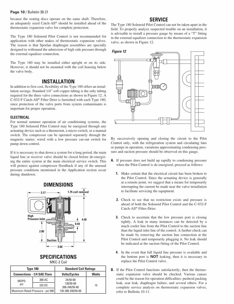
INSTALLATIONIn addition to first cost, flexibility of the Type 180 offers an instal-lation savings. Standard 1/4” soft copper tubing is the only tubing required for the three valve connections as shown in Figure 12. A C-032-F Catch-All® Filter Drier is furnished with each Type 180, since protection of the valve ports from system contaminants is important for proper operation.
ELECTRICALFor normal summer operation of air conditioning systems, the Type 180 Solenoid Pilot Control may be energized through any actuating device such as a thermostat, a micro-switch, or a manual switch. The compressor can be operated separately through the magnetic starter, wired with a low pressure cut-out switch for pump down control.
If it is necessary to shut down a system for a long period, the main liquid line or receiver valve should be closed before de-energiz-ing the entire system at the main electrical service switch. This will protect against compressor floodback if any of the unusual pressure conditions mentioned in the Application section occur during shutdown.
DIMENSIONS
SPECIFICATIONSMKC-2 Coil
SERVICEThe Type 180 Solenoid Pilot Control can not be taken apart in the field. To properly analyze suspected trouble on an installation, it is advisable to install a pressure gauge by means of a “T” fitting in the external equalizer connection to the thermostatic expansion valve, as shown in Figure 12.
By successively opening and closing the circuit to the Pilot Control only, with the refrigeration system and circulating fans or pumps in operation, variations approximating condensing pres-sure and suction pressure should be observed on this gauge.
A. If pressure does not build up rapidly to condensing pressure when the Pilot Control is de-energized, proceed as follows:
1. Make certain that the electrical circuit has been broken to the Pilot Control. Since the actuating device is generally at a remote point, we suggest that a means for temporarily interrupting the current be made near the valve installation to facilitate servicing the equipment.
2. Check to see that no restriction exists and pressure is
ahead of both the Solenoid Pilot Control and the C-032-F Catch-All® Filter-Drier.
3. Check to ascertain that the low pressure port is closing tightly. A leak in many instances can be detected by a much cooler line from the Pilot Control to the suction line than the liquid inlet line of the control. A further check can be made by removing the suction line connection at the Pilot Control and temporarily plugging it. No leak should be indicated at the suction fitting of the Pilot Control.
4. In the event that full liquid line pressure is available and the bottom port is NOT leaking, then it is necessary to replace the Pilot Control valve.
B. If the Pilot Control functions satisfactorily, then the thermo-static expansion valve should be checked. Various causes could be the reason for operation difficulties: pushrod packing leak, seat leak, diaphragm failure, and several others. For a complete service analysis on thermostatic expansion valves, refer to Bulletin 10-11.
Figure 12
Suction
3.17
HighPressure Inlet
Common2.00
2.66
0.444.50
1.75 coil removal
Type 180 Standard Coil Ratings
Connections - 1/4 SAE Flare Volts/Cycles Watts
MOPDpsi
300 AC 24/50-60120/50-60
208-240/50-60120-208-240/50-60
15225 DC
Maximum Rated Pressure - psi 500

Bulletin 30-21 / Page 11
INSTALLATION PRECAUTIONS1. Do not attempt installation of the valve before pumping the
entire system down.
2. The solenoid coil must not be energized unless it is installed on the valve. To do so would cause coil to overheat and burn out.
3. The solenoid coil should be fused in accordance with local codes.
4. If a service valve is installed ahead of a solenoid valve, it should be closed during service procedures. Do not use a solenoid valve as a safety shutoff while making repairs to the system. Be sure there is no liquid in the line between the service and solenoid valves when they are in the closed position that could create dangerous hydraulic pressures.
5. Do not twist the valve assembly by pulling or pushing on the enclosing tube or coil assembly.
6. Do not carry a coil assembly or complete valve by the coil leads. This could damage the coil and cause a coil burnout.
7. Electrically ground the valve body. Typically this is done through the fluid piping or the electrical conduit.
8. Before energizing the valve, verify that the supply voltage and frequency matches the solenoid coil marking.
SOLDERING PRECAUTIONSSolder connections on Sporlan Heat Reclaim Valves are copper. Any of the commonly used types of solder are satisfactory with these materials. Regardless of the type of solder used, it is important to avoid over-heating the valve. Extreme care should be taken when brazing connections to avoid damage to internal synthetic parts. The torch tip should be large enough to avoid prolonged heating of the connection during the brazing operation. Overheating can also be minimized by directing the flame away from the valve body. Cool body thoroughly after making each connection. As an extra precaution, a wet cloth may be wrapped around the valve body during the soldering operation.
CAUTION: When installing 1/4” flare pilot line connections, flare body MUST be supported with another wrench. On the 5D valve, the pilot valve body MUST be supported when tightening the 1/4” flare connection. Failure to do either of the above may cause leaks or valve damage.
WIRINGCheck the electrical specifica-tions of the coil to be sure that they correspond to the available electrical service. See page 3 for typical wiring schematics for single compressor systems.
The 1/2” BX conduit connection of junction box on the coil of Heat Reclaim Valves may be rotated to any position by loosen-ing the coil screw. Valves with four-wire dual voltage coil have a wiring diagram decal (see diagram above) on the coil housing or bracket. This illustrates which wires to connect for either 120, 208, or 240 volt operation. Wiring and fusing (when used) must comply with prevailing local and national wiring codes and ordinances.
TRANSFORMER SELECTION
TEMPERATURE RATINGS
REPLACEMENT PART KITS for8D, 12D, 16D, 8D-SC, 12D-SC, 16D-SC and 10GThe parts kit for the 3-Way Heat Reclaim Valves include the piston assembly. This requires separate kits for Bleed “B” and Non-Bleed “C” versions of the 3-Way Valves.
CAUTION: If you are replacing the internal parts on an older “B” style valve with split piston rings, you must use the existing piston and piston rings. Do not use the new piston assembly sup-plied with your parts kit. (See page 12.)
3-Way Valve Manufactured with Split Cast Iron Piston Rings and Honed Body Bore 8D7B 7-96 & Earlier 8D9B 7-96 & Earlier 12D11B 1-94 & Earlier 12D13B 1-94 & Earlier 16D17B 4-91 & Earlier
The parts kit contains two different gaskets for the pilot valve. Which ones are used depends on the pilot valve design.
The Tetraseal, part #641-6 is a flexible gasket and is used on design “AA” valves. These valves can be identified by the square groove on the bottom of the pilot valve.
The bottom of the pilot valve on the design “BB” valve is machined flat to accomodate the metal “Wolverine” gasket part #14000-5.
GENERAL INFORMATION 3-WAY VALVES
BLUE YELLOW RED BLACK
BLUE BLACK RED YELLOW
120-V 208-V240-V
CoilKit
24v/50-60c 120v/50-60c 240v/50-60cTransformer
RatingVolt-Amperes
Current Amperes For 100% ofRated MOPD
of ValveIn-rush Holding In-rush Holding In-rush Holding
MKC-1 1.90 0.63 0.39 0.14 0.19 0.09 60
MKC-2 3.10 1.40 0.60 0.26 0.31 0.13 100
BasicValve Type Coil Type
AmbientTemp.
Ratings °F
Max. FluidTemp.
Rating °F
Min. FluidTemp.
Rating °F8D, 12D, 16D, 10G MKC-1 120 240 -40
180 MKC-2 120 240 -40
Suitable for use with all Halogenated refrigerants.
Design “AA”Tetraseal (Groove)
Design “BB”Wolverine (Flat)
Bleed Hole

Page 1� / Bulletin 30-21
REPLACEMENT PARTS
Printed in the U.S. of A 25-407
Valve Type Kit Number Description of ContentsHeat Reclaim Valves / Split Condenser Valves
8D7B/8D9B KS-8DB
1 Pilot Body Gasket1 Stem and Seat Assembly1 Piston Assembly*1 Lower Body O-Ring1 Lower Body Gasket (8D ONLY)1 Upper Valve Seat (12D & 16D ONLY)
8D7C/8D9C KS-8DC8D9B-SC KS-8DB-SC8D9C-SC KS-8DC-SC12D11B/12D13B KS-12DB12D11C/12D13C KS-12DC12D11B-SC/12D13B-SC KS-12DB-SC12D11C-SC/12D13C-SC KS-12DC-SC
16D17B KS-16DB
1 Stem and Seat Assembly1 Upper Valve Seat1 Piston Assembly*1 or 2 Lower Body O-Ring(16D Valves dated 6-06 and after are welded construction. Stem andSeat Assembly Kits are not available.)
16D17B (12-03 and after) KS-16DB-A16D17C KS-16DC16D17C (12-03 and after) KS-16DC-A16D17B-SC KS-16DB-SC16D17B-SC (12-03 and after) KS-16DB-SC-A16D17C-SC KS-16DC-SC16D17C-SC (12-03 and after) KS-16DC-SC-A
Pilot Assembly 1 Enclosing Tube Tetraseal1 Coil Housing Screw1 Pilot Valve Assembly
8D & 12D KS-8D/12DP8D-SC & 12D-SC KS-8D/12DP-SC16D KS-16DP
1 Coil Housing Screw1 Pilot Valve Assembly
16D (12-03 and after) KS-16DP-A16D-SC KS-16DP-SC16D-SC (12-03 and after) KS-16DP-SC-A
Hot Gas Defrost Valves10G79B
KS-10G1 Enclosing Tube Gasket, 2 Pilot Assembly Gaskets1 Plunger Assembly, 1 Pushrod1 Seat Assembly, 1 Piston Assembly, 1 Valve Spring
10G711A, B, C10G713
Pilot Assembly 2 Pilot Assembly Gaskets1 Pilot Valve Assembly1 Coil Housing Screw, 1 Bottom Plate
10G-B KS-10GP-B10G-C KS-10GP-C
Enclosing Tube Kits10G KE-6 1 Enclosing Tube Assembly
1 Enclosing Tube Gasket1 Coil Housing Screw, 2 Body Screws (KE-3 Only)
16D/16D-SC KE-98D/12D, 8D-SC/12D-SC KE-8D/12D
* Use existing piston on valves with honed bore. See caution note on page 11.
RECOMMENDED TORQUE
Listed by Underwriters’ Laboratories, Inc. Guide-Y10Z File No. MH4576Listed by Canadian Standards Association Guide-440-A-O File No. 19953
Valve Series Enclosing TubeLocknut
Pilot ValveAssembly Locknut
Lower BodyLocknut
Body FlangeCap Screw Coil Screw
8D & 8D-SC 10-15 60-65 25 — 2.312D & 12D-SC 10-15 60-65 — 15-18 2.316D & 16D-SC 30-35 *** — 20-24 2.3
16D & 16D-SC(12-03 and after) 10-15 60-65 — 20-24 2.3
10G 10-15 60-65 60-65 — 2.3180 — — — — 2.3
*** The 16D pilot assembly is connected to the body with a pipe connection. Apply a light coat of #242 (blue) Loctite to the male pipe threads and torque to 30-60 ft.-lb.
April 2007 / BULLETIN 30-21
Installation and Servicing Instructions
3-Way Valves
CONTENTSB5D, 8D, 12D & 16D 3-Way Heat Reclaim Valves . . . . . . . . . . . . . 28D-SC, 12D-SC & 16D-SC 3-Way Split Condenser Valves . . . . . . 510G79B, 10G711B & 10G711C 3-Way Hot Gas Defrost Valves . . . 6180 Solenoid Pilot Control . . . . . . . . . . . . . . . . . . . . . . . . . . . . . . . . . 8General Information. . . . . . . . . . . . . . . . . . . . . . . . . . . . . . . . . . . . . . 11Replacement Parts Kits. . . . . . . . . . . . . . . . . . . . . . . . . . . . . . . . . . . 12