speed effects on far-field - nasa
TRANSCRIPT
NASA Technical Memorandum 10 0 5 12
-~ _ _ -
b (LlASk-TM-lW512) HSLfCOP1BR ML'II-BOTOE M88-11051 SPEED EFFECTS 015 PkR-FXBLD aCOUSTIC L E W I S (WASA) 20=p Avai l : RTIS EC AO3/rrP & O t
c s a 20& Unclas 63/71 0305442
Helicopter Main-Rotor Speed Effects on Far-Field Acoustic Levels
Arnold W. Mueller, Otis S. Childress,
and Mark Hardesty
October 1987
National Aeronautics and Space Administratton
Lngky-- Hampton. Virginia 23665
lNTRODUCTlON
.
The design of a helicopter is based on an understanding of many parameters and their interactions. For example, in the design stage of a helicopter, the weight, engine, and rotor speed must be considered along with the rotor geometry when considering helicopter operations. However, the relationship between the noise radiated from the helicopter and these parameters is not well understood, with only a limited set of model and full-scale field test data to study. In general, these data have shown that reduced rotor speeds result in reduced far-field noise levels.
This paper will review the status of a recent helicopter noise research project designed to provide experimental flight data to be used to further understand helicopter rotor-speed effects on far-field acoustic levels. with a McDonnell Douglas Helicopter Company model 500E helicopter operating with the rotor speed as the control variable over the range of 103% of the main-rotor speed (NR) to 75% NR and with the forward speed maintained at a constant value of 80 knots.
Preliminary results will be presented relative to tests conducted
OBJECTIVES AND APPROACH
There were two objectives of the research project. The first objective was to develop a far-field acoustics data base as a function of reduced rotor speeds for a current technology operational helicopter. Acoustics data, obtained with a linear microphone array; helicopter position tracking data, helicopter speed and systems data, and weather data were recorded during the flight tests. These data may be synchronized in time. The noise and position data may also be merged together with the weather data and reduced using a Langley Research Center developed technique to provide narrowband acoustics spectrum results (ref. 1). The resulting data base will have a high degree of confidence placed on these narrowband results for all positions of the helicopter along its flight track. The second objective was to use the results from this database to study the LaRC helicopter noise prediction program (ROTONET), which is an analytical tool designed to permit the use of acoustics as a consideration in the design of helicopters.
The research project was conducted within the framework of the joint NASNAmerican Helicopter Society (AHS) program, often referred to as the NR squared program (National Rotorcraft Noise Reduction). This is a technology development program for helicopter noise prediction and
reduction. It is a joint effort between industry and the government. Industry is represented by Boeing Vertol, Bell Helicopter, Sikorsky Aircraft, and McDonnell Douglas Helicopter Corporation (MDHC). The government is represented by NASA Langley, Ames, and Lewis Research Centers, and by associated U. S. Army Laboratories. Langley Research Center was designated as the lead NASA center. As a part of the program, an experimental version of a MDHC model 500E helicopter was flown at the NASA Wallops Flight Facility during the spring of 1986. LaRC researchers measured far-field noise levels generated by the helicopter when it was operated with two different tail-rotor designs and with a muffler attached and not attached to the helicopter engine. Late in the summer of 1986, tests were conducted with the helicopter operating with the capability of its rotor speed being slowed during flight. results of this test will be presented in this paper.
Preliminary
Normally helicopter rotor speeds are maintained within a narrow range of rpm during flight. However, during the NASNAHS program, MDHC personnel conducted a research investigation of the flight handling characteristics of an experimental version of a model 500E helicopter which could be operated at normal and reduced rotor speeds. The MDHC and LaRC agreed to measure the far-field acoustic pressures of the helicopter as part of the research project. MDHC provided a noise test plan, test site, helicopter position tracking measurements, and weather measurements. NASA personnel traveled to the test site and obtained the acoustic data with a linear array of 10 microphones. Once the noise data are merged with the position tracking data, they will be digitized and reduced to narrowband spectra by use of Fourier transforms. The acoustics data obtained from the microphone array will then be averaged to produce narrowband acoustics spectra for different noise emission angles along the flight track of the helicopter. Then these spectra will be corrected for propagation and weather effects and will be used in the ROTONET program to compare with different analytical predictions of noise levels.
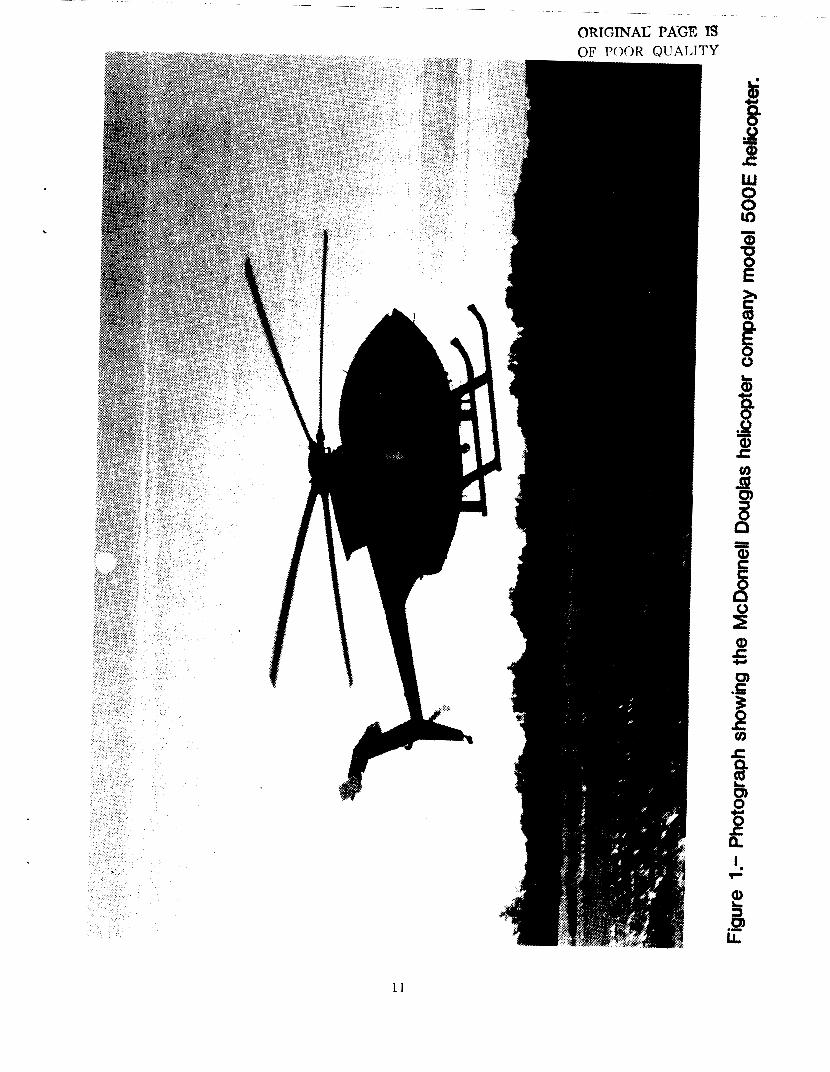
TEST HELICOPTER . The test helicopter used in this project is shown in figure 1. This is
a light weight helicopter (approximately 1400 Ibs.) which may carry a pi Dt and five passengers. It has a nominal cruising speed of 125 knots at sea level, has a five-bladed main rotor and a two-bladed tail rotor. Rotor tip speeds are approximately 700 fps for each rotor with 103% NR rotor speeds of 492 rpm and 2933 rpm for the main and tail rotors. For the
I
2
purposes of tl iis research effort, extensive developmen, tests were required to permit safe flight operations at the desired reduced speeds. A special fuel flow governor was obtained along with a specially designed governor actuator which had to be flight tested. Additionally, at some of the rotor speeds vibration damping was required to be added to the tail skid to reduce empenage loads to safe levels. During all flights, instrumentation onboard the helicopter measured and recorded flight altitude, main rotor rpm, engine torque, airspeed, stick positions and empenage loads and vibration levels.
ACOUSTIC MEASUREMENT SYSTEM
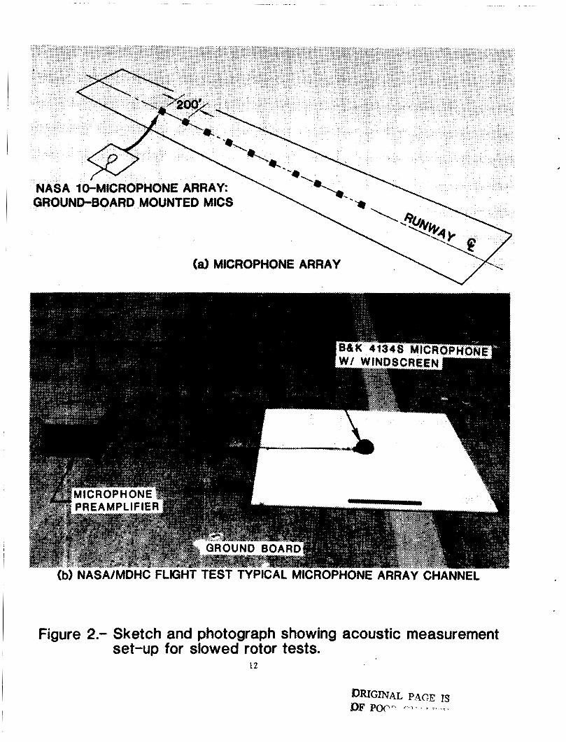
Figure 2(a) is a diagram of the microphone placement at the test site. The multiple-microphone linear array system used to obtain the acoustic data consisted of ten pressure-type condenser microphones (1/2 inch diameter) fitted with grid caps and covered by wind screens. The microphones were linearly spaced along the runway centerline with 200 feet distance between adjacent microphones. This preserved statistical independence for each microphone signal at acoustic frequencies above 10 Hz and at each helicopter speed for which data were obtained (ref. 2). The microphones of this linear array, shown in the photograph in figure 2(b), were placed on ground boards (4' x 4' x 314" plywood), and oriented for acoustically grazing incidence angles that were maintained for the flight test.
Each microphone signal from the linear array was amplified or attenuated as necessary and recorded on an analog wide band 14 track magnetic tape recorder operating at a tape speed of 15 inches per second in the FM mode. The linearity, sensitivity, distortion, and noise floor of each acoustic system (microphone, preamplifier, line driver, amplifier and recording tape track) were calibrated in the laboratory and documented to be linear to within +/-1 dB before it was placed in the field. The frequency range of calibration was 5 Hz to 10 kHz. A piston phone operating at 250 Hz, 124 dB sound pressure level (SPL), was used in the field for calibration at the beginning and end of each day. Also, at the beginning and conclusion of data acquisition for each flight test, ambient noise levels were recorded. Since there were several possibilities for contaminating noise sources (a major airport about 10 miles away, a small airport about 5 miles away, and an interstate highway 1 mile from the test area), flight noise data were obtained during early morning hours. At this time, ambient noise was generally low, thus providing the best possible signal-to-noise ratio.
3
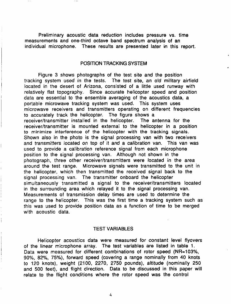
Preliminary acoustic data reduction includes pressure vs. time measurements and one-third octave band spectrum analysis of an individual microphone. These results are presented later in this report.
POSITION TRACKING SYSTEM
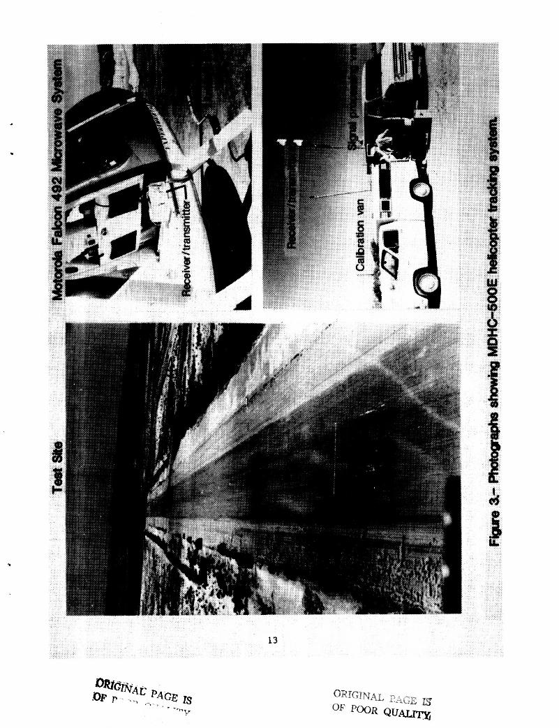
Figure 3 shows photographs of the test site and the position tracking system used in the tests. The test site, an old military airfield located in the desert of Arizona, consisted of a little used runway with relatively flat topography. Since accurate helicopter speed and position data are essential to the ensemble averaging of the acoustics data, a portable microwave tracking system was used. This system uses microwave receivers and transmitters operating on different frequencies to accurately track the helicopter. The figure shows a receiverhansmitter installed in the helicopter. The antenna for the receiverAransmitter is mounted external to the helicopter in a position to minimize interference of the helicopter with the tracking signals. Shown also in the photo is the signal processing van with two receivers and transmitters located on top of it and a calibration van. This van was used to provide a calibration reference signal from each microphone position to the signal processing van. Although not shown in the photograph, three other receiverAransmitters were located in the area around the test range. the helicopter, which then transmitted the received signal back to the signal processing van. simultaneously transmitted a signal to the receiver/transmitters located in the surrounding area which relayed it to the signal processing van. Measurements of transmission delay times are used to determine the range to the helicopter. This was the first time a tracking system such as this was used to provide position data as a function of time to be merged with acoustic data.
Microwave signals were transmitted to the unit in
The transmitter onboard the helicopter
TEST VARIABLES
Helicopter acoustics data were measured for constant level flyovers of the linear microphone array. The test variables are listed in table 1. Data were measured for different combinations of rotor speed (NR=1 O3%, 90%, 82%, 75%), forward speed (covering a range nominally from 40 knots to 120 knots), weight (2100, 2270, 2750 pounds), altitude (nominally 250 and 500 feet), and flight direction. Data to be discussed in this paper will relate to the flight conditions where the rotor speed was the control
4
variable. The other factors were maintained at constant values of 80 knots foward speed, 2270 pounds gross weight, and a nominal flight altitude of 250 feet on a 300 degree magnetic heading.
SOURCES OF ROTOR NOISE, DIRECTIVITY, AND NOISE TRENDS
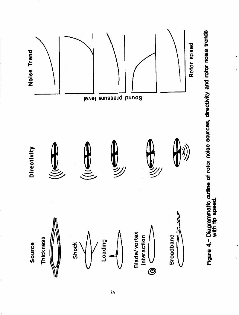
The sources of rotor noise, directivity, and the trend of the noise levels as a function of advancing rotor tip Mach number are shown in figure 4 (refs. 3-5). Blade thickness and shock noise tend to have directivity patterns in the plane of the rotor and noise levels which tend to decrease with a reduction in advancing tip Mach number. Once the advancing tip Mach number reaches the speed at which shock cells no longer form on the blade, this noise source ceases to exist. Both loading of the rotor blade and interactions of one rotor blade with vortices shed from another blade passing through the air (bladehortex interaction or BVI), tend to have directivity patterns which occur beneath the rotor plane. Noise levels associated with these sources tend to occur from about 10 or 15 degrees to 60 or more degrees beneath the plane of the rotor. BVI noise generally decreases as the rotor speed increases because at the higher speeds the vortices don't have time to mature before an advancing blade cuts a vortex. Broadband noise sources result from turbulence shed from the trailing edge of the rotor. Radiation of this noise principally occurs at angles perpendicular to the plane of the rotor tip. Preliminary data presented in this paper were obtained approximately in the plane of the main and tail rotors and are associated with the thickness noise source. Shock noise is not a contributor to the noise levels since blade tip speeds are approximately 700 feet per second, much below the approximate 1120 fps sound speed.
THEORETICAL FAR-FIELD ACOUSTIC PULSE SHAPE
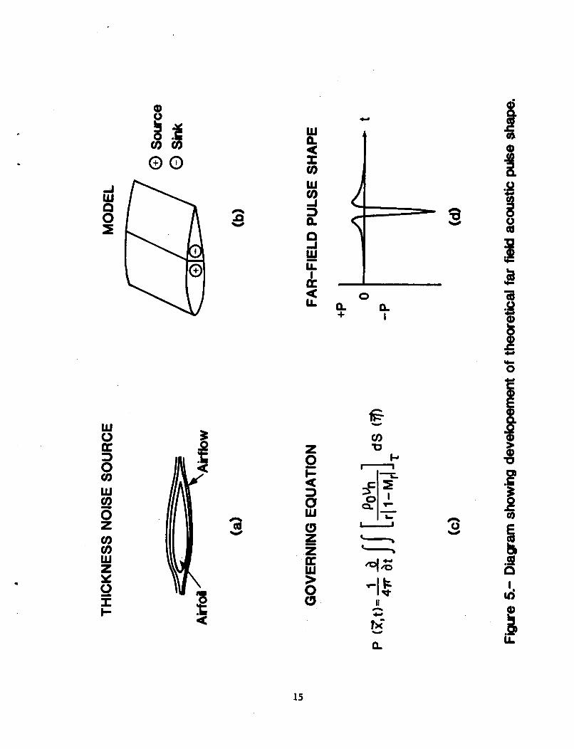
Figure 5 presents the far-field acoustic results of air flow over a helicopter rotor (ref. 6). The volume of air flowing across the airfoil, fig. 5(a) , may be modeled mathematically as a distribution of "sources and sinks" of mass flow, as sketched in fig. 5(b). It has been shown (ref. 7) that most of the acoustic radiation is generated at the outer tip of the rotor. The fundamental governing equation used to derive the far-field acoustic thickness noise from a rotor is presented in fig. 5(c). This equation is the result of considering only the linear term of the general Ffowcs Williams-Hawkings equation describing the acoustic pressure radiated by the helicopter rotor. The sources and sinks must be summed
5
over the surface area of the rotor outer tip with consideration given to the retarded times between when they occur and the time required for propagation to the observer in the far field. Time differentiation of the double integral results in the theoretical pressure distribution sketched in figure 5(d). and a much larger negative pressure.
This pulse has a characteristically small positive pressure
EXPERIMENTALLY MEASURED FAR-FIELD ACOUSTIC PULSE SHAPE
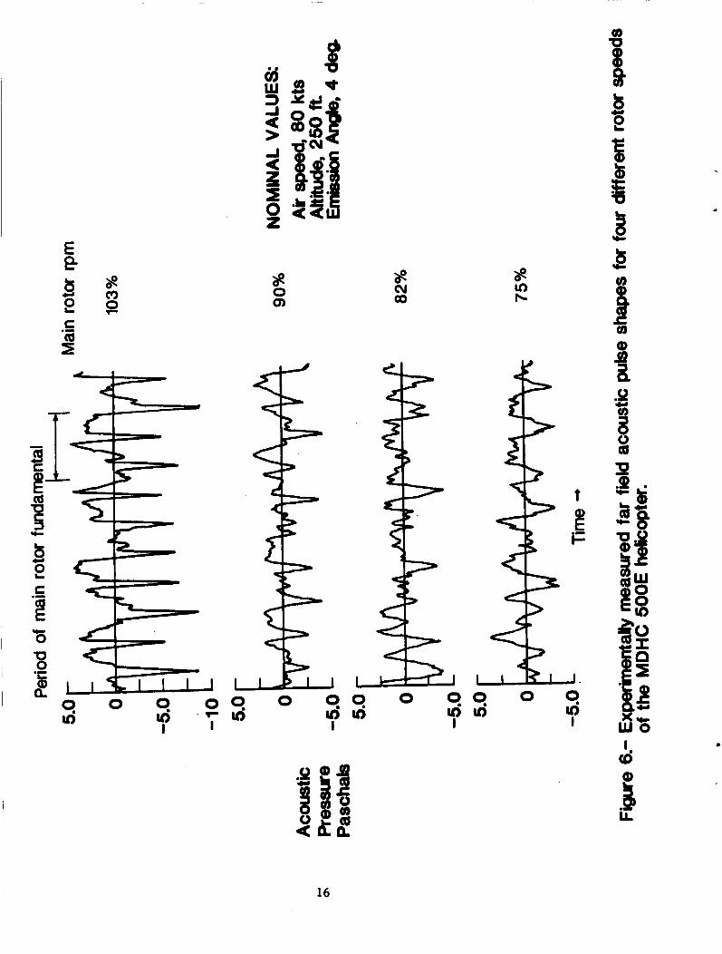
Experimental pressure pulses measured in the far-field of the rotor plane are presented in figure 6. This figure shows the pressure plotted as a function of time, all on the same scale, for the rotor speeds of 103%, 90%, 82%, and 75% NR. These data were measured when the helicopter flew at a constant speed of 80 knots at an altitude of 250 feet. The noise emission angle is approximately 4 degrees. The data show shapes typical of the theoretical pressure shape, exhibiting the small positive and large negative pressure pulses. speed decreases, the magnitudes of the pressures decrease, with the largest change occurring in the negative pressure. These data have been transformed from the time domain to the frequency domain using Fourier 1
transforms. Preliminary one-third octave band spectral results are shown in the next figure (fig. 7).
Additionally, it is observed that as the rotor
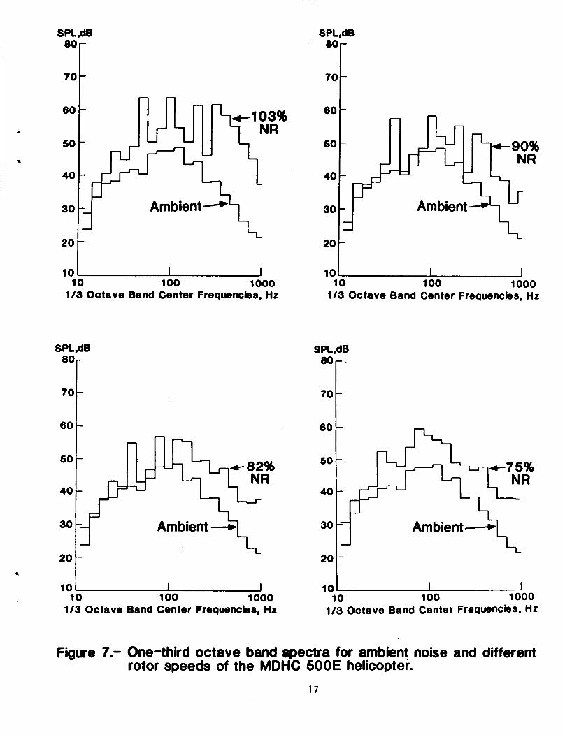
ONE-THIRD OCTAVE BAND SPECTRA
Figure 7 presents the one-third octave spectral analysis of the data shown in figure 6. The top curve, in each of the parts of figure 7, is the spectrum measured for the different rotor speeds. For comparison, the ambient noise spectrum measured before the flight of the helicopter is shown as the bottom curve. Table 2 presents the measured overall and one-third octave band SPL's for the Doppler shifted main and tail rotor fundamental frequencies of the data presented in figure 7. The data in figure 7 and table 2 show that as the rotor speed is reduced the noise levels and the acoustic frequencies of both the main and tail rotor are reduced, except for the 75% NR condition. At 75% NR, the overall SPL increased by about 2 dB from the 82% NR run, with this increase showing up in the 80 Hz one-third octave band. This change may be due to extraneous noise and not to the helicopter. It was noted earlier that the location where data were measured was about one mile from an interstate highway .
6
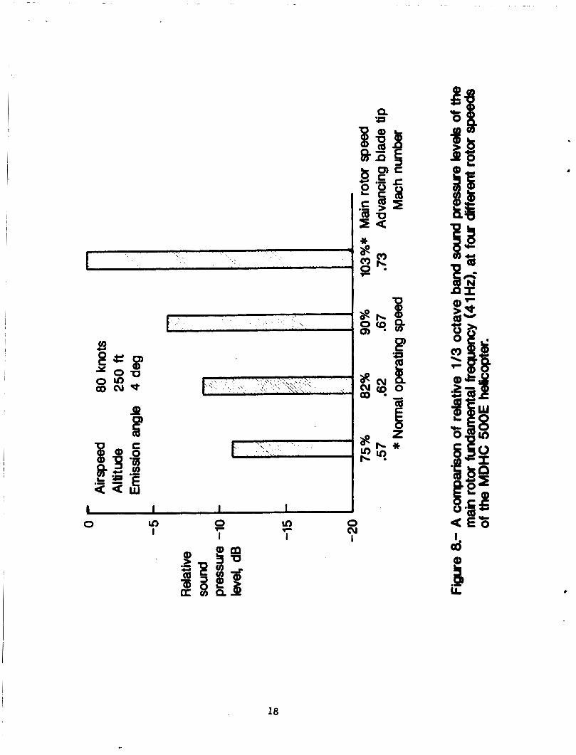
Relative one-third octave band SPL's of the Doppler received main- rotor fundamental frequency (from Table 2) are presented in figure 8. These relative SPL's are presented as a bar chart with the advancing blade tip Mach number and percent of NR of the main-rotor speed listed on the abscissa. Amplitudes of the SPL's were made relative to the measured SPL at 103% NR. The data show that reducing the main-rotor speed from 103% to 90% (12.6% reduction) NR resulted in a 6.1 dB reduction of the far-field noise level. The succeeding rotor speed decreases provided 2.7 and 2.2 dB further noise reductions. Thus, these preliminary results show that reducing the main-rotor speeds from 103% to 75% of NR, a 27% reduction in rotor speed, reduced the measured in plane thickness noise at an emission angle of 4 degrees by approximately 11 dB.
CONCLUDING REMARKS
These tests have provided an opportunity to obtain a unique set of flight data. Far-field noise measurements were made for a McDonnell Douglas experimental model 500E helicopter operating in level flight with the main-rotor speed as the control variable. Position tracking of the helicopter was accomplished using a portable microwave tracking system. The reduction of the main-rotor speed by 27% produced a corresponding far-field noise reduction of 11 dB in the one-third octave band containing the main-rotor fundamental frequency. reduction, 6.1 dB, occurred when the normal operating speed of the rotor was reduced from 103% NR to 90% NR.
The largest individual noise
7
REFERENCES
1. Mueller, Arnold W.; and Preisser, John S.: Flight Test of a Pure-Tone Acoustic Source. NASA TP-1898, 1981.
2. Stouder, D. J.: Narrow-band Spectrum Analysis Techniques for Processing Airplane Flyover Noise Data. Presented at the AlAA 6th Aeroacoustics Conference, AlAA 80-1 053, June 1980.
3. Splettstoesser, Wolf R.; Klaus, J.; Schmitz, Frederic H.; and Boxwell, Donald R.: Model Rotor Hig h-Speed Impulsive Noise- Parameter Variations and Full-Scale Comparisons. Presented at the 39th Annual National Forum of the American Helicopter Society, May 1983.
4. Brooks, Thomas F.; Schlinker, Robert H.: Progress in Rotor Broadband Noise Research. Vertica, vol. 7, no. 4, 1983, pp. 287-307.
5. Schlinker, Robert H.; Amiet, Roy K.: Helicopter Rotor Trailing Edge Noise. NASA CR-3470, November 1981.
6. Schmitz, F. H.; Yu, Y. H.: Helicopter Impulsive Noise: Theoretical and Experimental Status. Journal of Sound and Vibration (1 986), 109(3), pp. 361-422.
7. Farassat, F.: Theory of Noise Generation from Moving Bodies with an Application to Helicopter Bodies. NASA TR R-451, December 1975.
a
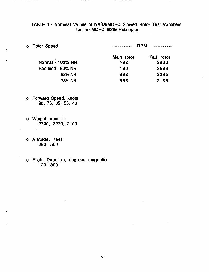
TABLE 1.- Nominal Values of NASNMDHC Slowed Rotor Test Variables for the MDHC 500E Helicopter
o Rotor Speed
Normal - 103% NR
82% NR Reduced - 90% NR
75% NR
o Forward Speed, knots 80, 75, 65, 55, 40
o Weight, pounds 2700, 2270, 2100
o Altitude, feet 250, 500
Main rotor Tail rotor 492 2933 430 2563 392 2335 358 21 36
o Flight Direction, degrees magnetic 120, 300
.
9
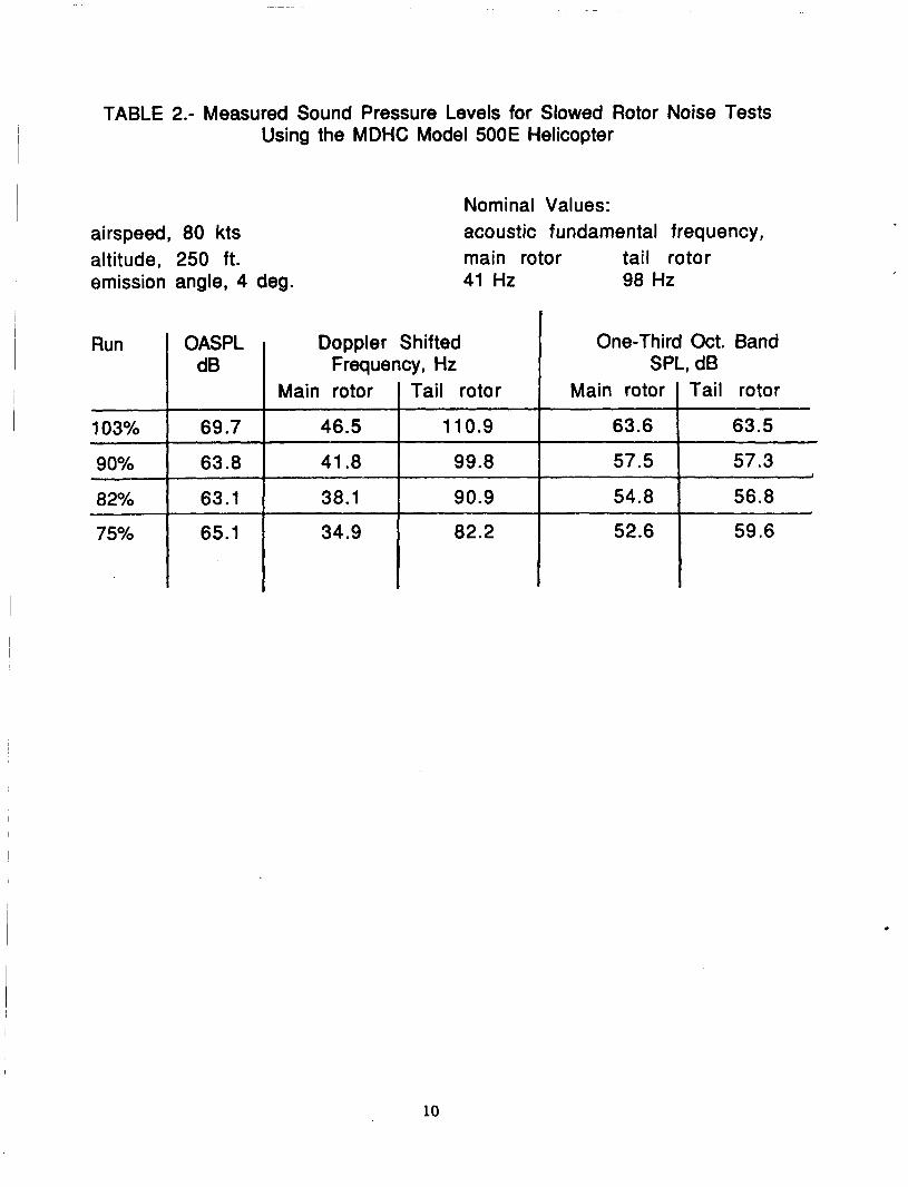
TABLE 2.- Measured Sound Pressure Levels for Slowed Rotor Noise Tests Using the MDHC Model 500E Helicopter I
I
Doppler Shifted Frequency, Hz
Main rotor Tail rotor
46.5 11 0.9
41.8 99.8
38.1 90.9
34.9 82.2
airspeed, 80 kts altitude, 250 ft. emission angle, 4 deg.
I
One-Third Oct. Band SPL, dB
Main rotor Tail rotor
63.6 63.5
57.5 57.3
54.8 56.8
52.6 59.6
I
Nominal Values: acoustic fundamental frequency, main rotor tail rotor 41 Hz 98 Hz
I
Run
103%
90%
82%
75%
OASPL dB
69.7
63.8
63.1
65.1
10
~~~ ~~
ORIGINAZ; PAGE IS OF POOR QUATATTY
w 0 0 v)
t
c a 0) 0 E
e E
11
I
(d MICROPHONE ARRAY
Figure 2.- Sketch and photograph showing acoustic measurement set-up for slowed rotor tests.
12
13
n Q) Q)
sf-
a
L
c, 0 0
14
c
4 W
0 2 n
~ rc 0
n 0 Y
n a Y
0 ~
e e + I
cc 0
Y
u
> 0 (3 It
n . . Y
n 0 Y
&J .s n I ui
15
0 I r
0 0 0 ui I
ui
8 0 Q)
0 0 0 ui I
ui
16
0 9 u) I
9 u)
0
SPLdB
70 Ool
IJ 5 Y
2o t 10
~~ ~
100 1000 113 Octave Band Center Freqwncies, H t
-f 60
82% NR
40
Ambient 3 IJ I
2ot L
10 L 10 100 1000
113 Octave Band Center Frequencies, Hz
SPL 0c
7(1
60
so
40
30
20
10 10 100 1000
113 Octave Band Center Frequencies, H r
SPL,dB
,Or.
70 t 80
so
40
30
10, 10 100 1000
113 Octave Band Center Frequencies, Hr
Figure 7.- One-third octave band spectra for ambient noise and different rotor speeds of the MDHC 500E helicopter.
17
1 I I I 1 9 r
0 cv In I I I
In I
0 I
od
18
c
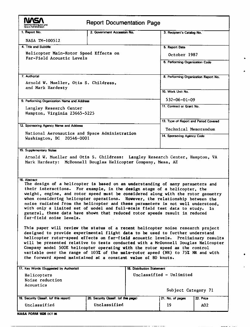
Report Documentation Page 1. Report No.
NASA TM-100512
2. Government Accession No.
7. Author(s1
Arnold W. Mueller, O t i s S. Chi ld res s , and Mark Hardesty
7. Key Words ( S u g m e d by Author(s))
Hel i cop te r s Noise r educ t ion Acoust ics
9. Performing Organization Name and Address
Langley Research Center Hampton, V i r g i n i a 23665-5225
18. Distribution Statement
Unclas s i f i ed - Unlimited
Subjec t Category 71
12. Sponsoring Agency Name and Address
9. Security Classif. (of thu report)
Unclas s i f i ed
Nat iona l Aeronaut ics and Space Adminis t ra t ion Washington, DC 20546-0001
20. Security Classif. (of thb 21. No. of pages 22. Price
Unclas s i f i ed 19 A0 2
5. Supplementary Notes
3. Recipient's Catalog No.
5. Report Date
October 1987 6. Performing Organization Code
8. Performing Organization Report No.
10. Work Unit No.
532-06-01-09 11. Contract or Grant No.
13. Type of Report and Period Covered
Technical Memorandum 14. Sponsoring Agency Code
Arnold W. Mueller and O t i s S. Chi ldress : Langley Research Center , Hampton, VA Mark Hardesty: McDonnell Douglas Hel icopter Company, Mesa, AZ
6. Abstract The des ign of a h e l i c o p t e r is based on an understanding of many parameters and t h e i r i n t e r a c t i o n s . For example, i n the design stage of a h e l i c o p t e r , the weight , engine, and r o t o r speed must be considered along with the r o t o r geometry when cons ider ing h e l i c o p t e r opera t ions . However, the r e l a t i o n s h i p between the no i se r ad ia t ed from t h e h e l i c o p t e r and these parameters is not w e l l understood, with only a l imi t ed set of model and f u l l - s c a l e f i e l d test d a t a t o study. I n g e n e r a l , t hese d a t a have shown t h a t reduced rotor speeds r e s u l t i n reduced f a r - f i e l d noise l eve l s .
This paper w i l l review the s t a t u s of a recent h e l i c o p t e r no ise research p r o j e c t designed t o provide experimental f l i g h t d a t a t o be used t o f u r t h e r understand h e l i c o p t e r rotor-speed e f f e c t s on f a r - f i e l d a c o u s t i c l eve l s . Prel iminary r e s u l t s w i l l be presented r e l a t i v e t o tests conducted with a McDonne11 Douglas Hel icopter Company model 500E h e l i c o p t e r ope ra t ing wi th the r o t o r speed as the c o n t r o l v a r i a b l e over t he range of 103% of t h e main-rotor speed (NR) t o 75% NR and wi th the forward speed maintained at a cons tan t value of 80 knots.