spectrum® kr2i / kmpi tff systems
TRANSCRIPT

Spectrum® KR2i / KMPi TFF Systems
USER GUIDE AND OPERATING INSTRUCTIONS
Spectrum® KrosFlo® Research 2i TFF System
Spectrum® KrosFlo® MiniKros Pilot i TFF System

The information contained in this document is subject to change without notice. Repligen Corporation makes no warranty of any kind with regard to this material, including, but not limited to, the implied warranties of merchantability and fitness for a particular purpose. Repligen Corporation shall not be liable for errors contained herein or for incidental or consequential damages in connection with the furnishing, performance, or use of this material. No part of this document may be photocopied, reproduced, or translated to another language without the prior written consent of Repligen Corporation. For further information, please contact Repligen Corporation at www.repligen.com. © 2018 Repligen Corporation. All rights reserved. The trademarks mentioned herein are the property of Repligen Corporation and/or its affiliate(s) or their respective owners. Repligen’s TFF System (KR2i / KMPi) meets strict quality control standards and is warranted against defects in material and workmanship for a period of two (2) years from date of shipment. The information contained herein is believed to be accurate and is offered in good faith for the convenience of the user. PRODUCTS ARE FURNISHED UPON THE CONDITION THAT THE USER ASSUMES ALL RISKS AND LIABILITIES AND THAT NEITHER THE SELLER NOR MANUFACTURER SHALL BE LIABLE FOR ANY LOSS OR DAMAGE, DIRECT OR CONSEQUENTIAL, ARISING FROM THE USE OF THESE PRODUCTS. Spectrum®, KrosFlo®, MicroKros®, MidiKros® and MiniKros® are registered trademarks of Repligen Corporation. Microsoft®, Windows® and Excel® are registered trademarks of Microsoft Corporation. C-Flex® and Pharmapure® are registered trademarks of Saint-Gobain. MasterFlex® is a registered trademark of Cole-Parmer. Trademarks bearing the ® symbol in this publication are registered in the U.S. and in other countries. This document copyright © 2018 Repligen Corporation. All rights reserved. Reproduction prohibited except by permission of the copyright owner. Visit http://spectrumlabs.com/filtration/ProcessSystems.html for more information. Customer Support [email protected] 310-885-4600 Technical Support [email protected] Spectrum A Repligen Brand 18617 S Broadwick St. Rancho Dominguez, CA 90220 www.spectrumlabs.com
Table of Contents
Introduction ......................................................................................................................... 6
Safety Precautions ................................................................................................................ 7
Explanation of Symbols: ..................................................................................................................... 7
WARNING: Product Use Limitation .................................................................................................... 8
Specifications ....................................................................................................................... 8
KR2i Specifications .............................................................................................................................. 8
KMPi Specifications ............................................................................................................................ 9
KONDUiT Specifications .................................................................................................................... 10
System Configuration and Major Components ..................................................................... 12
4.1 Pump Drive, Pump Head, & Integrated Pressure Monitor ...................................................... 12
4.2 Mounting Hardware ................................................................................................................. 12
4.3 Octopus Cables ........................................................................................................................ 12
System Parts List................................................................................................................. 12
Materials of Construction ................................................................................................... 13
Setup and Operation .......................................................................................................... 13
7.1 Basic Setup ............................................................................................................................... 13
7.2 Manual Mode Setup ................................................................................................................ 15
7.3 C. Mode Setup.......................................................................................................................... 16
7.4 C/D and C/D/C Mode Setup ..................................................................................................... 16
7.5 C/D/D/C Mode Setup ............................................................................................................... 17
7.6 CFC Mode Setup ....................................................................................................................... 18
7.7 CF/D/C Mode Setup ................................................................................................................. 19
7.8 Ctrl Mode ................................................................................................................................. 20
7.9 System Setup Using KF Comm Pump Control Window ........................................................... 20
7.9.1 KF Comm User Interface ............................................................................................... 20
7.9.2 Entering System Settings .............................................................................................. 23
7.10 Using Pump Interface ............................................................................................................... 30
7.10.1 Keypad ........................................................................................................................... 30
7.10.2 Main Screen .................................................................................................................. 31
7.10.3 Remote Control Of Auxiliary Pumps and Valves ........................................................... 32
7.10.4 System Settings ............................................................................................................. 35
7.10.5 Hardware Setup ............................................................................................................ 35
7.11 Pressure Calibrate .................................................................................................................... 37
7.12 Alarms and Stops ..................................................................................................................... 37
7.13 Tubing Calibration .................................................................................................................... 38
System Functionality .......................................................................................................... 39
8.1 Pump Controls ......................................................................................................................... 39
8.1.1 Overview ....................................................................................................................... 39
8.2 Detailed Pump Mode Operation .............................................................................................. 40
8.2.1 Concentration Mode ..................................................................................................... 40
8.2.2 Concentration/Diafiltration Mode ................................................................................ 41
8.2.3 Concentration 1/Diafiltration/Concentration 2 Mode ................................................. 43
8.2.4 Concentration 1/Diafiltration 1/Diafiltration 2/Concentration 2 Mode ....................... 44
8.2.5 Constant Feed Concentration Mode ............................................................................. 45
8.2.6 Constant Feed/Diafiltration/Concentration Mode ....................................................... 46
8.2.7 Ctrl Mode ...................................................................................................................... 47
8.3 Running the TFF System ........................................................................................................... 48
8.4 Pump Mode Status Timeout Display........................................................................................ 48
Pump Head Setup and Operation ........................................................................................ 49
9.1 Introduction ............................................................................................................................. 49
9.2 Specifications ........................................................................................................................... 49
9.3 KR2i Pump Head Operation ..................................................................................................... 52
9.4 KMPi Pump Head Operation .................................................................................................... 55
Auxiliary Component Setup and Operation.......................................................................... 58
10.1 Auxiliary Scales ......................................................................................................................... 58
10.1.1 Installation .................................................................................................................... 58
10.2 Auxiliary Pumps........................................................................................................................ 59
10.2.1 Installation .................................................................................................................... 59
10.2.2 Auxiliary Pump Settings ................................................................................................ 61
10.3 Automatic Backpressure Valve ................................................................................................ 61
10.3.1 Installation .................................................................................................................... 61
10.3.2 Operation ...................................................................................................................... 62
10.3.3 Automatic Backpressure Valve Settings........................................................................ 62
10.4 KONDUiT .................................................................................................................................. 62
10.4.1 System Configuration and Major Components............................................................. 62
10.4.2 Installation .................................................................................................................... 63
10.4.3 Software/Firmware Operation...................................................................................... 65
10.4.4 KONDUiT Software/Firmware Configuration ................................................................ 65
10.4.5 Software Operation ....................................................................................................... 65
10.4.6 Firmware Operation ...................................................................................................... 66
10.4.7 Maintenance ................................................................................................................. 68
KF Comm Software ............................................................................................................. 68
11.1 Introduction ............................................................................................................................. 68
11.2 Installing and Updating TFF System Software and Firmware with KF Comm Software .......... 69
11.3 USB Connection ....................................................................................................................... 70
11.4 Opening and Configuring the KF Comm Workbook Template ................................................ 71
11.5 Data Collection Tools ............................................................................................................... 72

11.6 Worksheets Overview .............................................................................................................. 73
Basic Concepts of Tangential Flow Filtration ........................................................................ 74
12.1 Introduction ............................................................................................................................. 74
12.2 Concentration .......................................................................................................................... 74
12.3 Diafiltration .............................................................................................................................. 75
Troubleshooting ................................................................................................................. 75
Replacement and Auxiliary Parts ......................................................................................... 76
Index .................................................................................................................................. 77

6 400-12355-000 Rev. 03
KR2i / KMPi TFF Systems Introduction
Introduction The KR2i [KrosFlo® Research 2 integrated] and KMPi [KrosFlo® MiniKros® Pilot integrated] Tangential Flow Filtration (TFF) Systems are ideal automated pump systems for processes ranging from 1ml to 10L and 0.5L to 500L respectively. The systems consist of a digital peristaltic pump, man/machine interface with graphical LCD display, Pump Head, digital readouts of pressure values with automated shut-off controls, module stand, and real-time data collection software KF Comm. The KR2i can mount up to two 2.3 LPM KR2i Easy-Load Pump Heads or two 2.9 LPM KR2i High-Performance Pump Heads. The KMPi can mount up to two 13 LPM KMPi Easy-Load Pump Heads or one 17 LPM KMPi High-Performance Pump Head. When equipped with optional auxiliary components, the TFF system's automated functions are extended further. Through the combination of specific set-points measured through the TFF system's auxiliary pumps, scales, KONDUiT and backpressure valves, the TFF system is able to carry out complicated TFF processes with improved accuracy and efficiency. The peristaltic pump handles abrasive slurries, corrosive fluids and highly viscous fluids with minimal wear. The pump also allows only the tubing and other tube material to come in contact with the fluid, has no valves to clog, and has smooth and easy-to-clean inner surfaces. Its performance has proven that the bidirectional and self-priming TFF system has low shear, is capable of running dry and pumping fluids with high quantities of entrained air, has high volumetric efficiency, and a motor speed repeatability of 0.1 percent to maximize productivity. The KR2i is the ideal system for small volume, R&D scale microfiltration and ultrafiltration due to its compact footprint and versatility. The KMPi has been designed to be used with Spectrum’s ProConnex® Flowpaths, which are sterile, fully-assembled and disposable process flowpaths for TFF. The KMPi and Pro-Connex sets are ideal for upstream TFF microfiltration and downstream TFF ultrafiltration. The disposable or dedicated flowpath—including the filter, pressure transducers, tubing and fittings—eliminates the possibility of cross contamination. TangenX flat-sheet TFF cassettes can also be used on both the KR2i and KMPi. The hollow fiber (HF) membrane modules provide excellent performance for sample concentration, fractionation and washing while avoiding membrane fouling and maximizing product recovery. TangenX cassettes are ideal for applications where the inner screen increases turbulence and gives high permeate flux for viscous proteins, oligosaccharides, and viruses for example. The disposability of both the cassettes and HF filters eliminates not only the potential for cross-contamination and costs associated with cleaning and rinsing, but also the difficulties associated with validating reusable membranes. Used in conjunction with HF membrane modules, or TangenX cassettes, the TFF systems offer the following advantages:
• Faster processing times • Superior filtration dynamics • Filter disposability • Lower costs

7 400-12355-000 Rev. 03
KR2i / KMPi TFF Systems Safety Precautions
• Direct and easy scale-up for production volumes
Safety Precautions DANGER: High voltages exist and are accessible. Use extreme caution when servicing internal components. Remove power from the pump before any cleaning operation is started. WARNING Remove power from the pump before attempting any maintenance. WARNINGS: Tubing breakage may result in fluid being sprayed from pump. Use appropriate measures to protect operator and equipment. Turn drive off before removing or installing tubes. Fingers or loose clothing could get caught in drive mechanism. CAUTIONS: Power must be turned off before connecting the external remote control cable to prevent damage to the drive. Do not contaminate the lubricant in the container, on the shaft or on the seal with foreign material. Failure to observe this precaution may result in damage to the seal and premature failure of the seal. No foreign matter should be allowed under the gasket on the back of the front plate or under the heads of the screws. Failure to observe this precaution may result in leakage during washdown of the drive. CAUTION: To avoid electrical shock, the power cord protective grounding conductor must be connected to ground. Not for operation in wet locations as defined by EN61010-1. CAUTION: Keep fingers away from rotor while pump is in operation. Stop pump before loading or unloading tubing. Explanation of Symbols: CAUTION: Risk of Danger. Consult Operating Instructions for nature of hazard and corrective actions. CAUTION: Risk of crushing. Keep fingers away from rotor while pump is in operation. Stop pump before loading or unloading tubing. CAUTION: Hot surface. Do not touch. CAUTION: Risk of electric shock. Consult Operating Instructions for nature of hazard and corrective actions.

8 400-12355-000 Rev. 03
KR2i / KMPi TFF Systems Specifications
WARNING: Product Use Limitation Risk of Danger. Consult Operating Instructions for nature of hazard and corrective actions. This product is not designed for, nor intended for use in patient connected applications; including, but not limited to, medical and dental use, and accordingly has not been submitted for FDA approval. This product is not designed for, nor intended for use in hazardous duty areas as defined by ATEX or the NEC (National Electrical Code); including, but not limited to use with flammable liquids. Consult the factory for products suitable for these types of applications. ENVIRONMENTAL Waste electrical products should not be disposed of with household PROTECTION: waste. Please recycle where facilities exist. Check with your Local Authority or retailer for recycling advice.
Specifications KR2i Specifications
Output
Speed: 0.1 to 600 rpm Torque output, Maximum: 180 oz-in (13 kg•cm) 540 oz-in Starting Speed regulation: Line ±0.1% F.S. Load ±0.1% F.S. Drift ±0.1% F.S. Display: 128 x 64 LCD w/ LED Backlight Pressure Sensor Limits: -9.99 to 75 psi Input Supply voltage limits: 90 to 260 Vrms @ 50/60 Hz (Universal Input) Current, Maximum: 2.2A @ 115 Vrms, or 1.1A @ 230 Vrms Construction Dimensions (L × W × H): 10.5 in × 8 in × 8 in (267 × 203 × 203 mm) Weight: 13 lb (5.9 kg) Enclosure Rating: IP33 Environment

9 400-12355-000 Rev. 03
KR2i / KMPi TFF Systems Specifications
Temperature, Operating: 0° to 40°C (32° to 104°F) Temperature, Storage: –25° to 65°C (–13° to 149°F) Humidity (non-condensing): 10% to 90% Altitude: Less than 2000 m Pollution Degree: Pollution Degree 2 Compliance: (For ETL Mark): UL 61010-1, CAN/CSA C22.2 No. 61010-1 (For CE Mark): EN61010-1 (EU Low Voltage Directive) and EN61326 (EU EMC Directive) RoHS KMPi Specifications Output Speed: All models 0.1 to 650 rpm Torque output, max. All models 520 oz-in (37.4 kg • cm) 1560 oz-in Starting Speed regulation: All models Line ±0.1% F.S. Load ±0.1% F.S. Drift ±0.1% F.S. Display: All models 128 x 64 LCD w/ LED Backlight Remote outputs: All models Voltage speed output (0-10V DC @ 1 kΩ min) All models Current speed output (0-10 mA @ 0-600Ω) All models Tach output (100 to 6500 Hz, 50% duty cycle, 10 Hz/rpm) All models Motor running output (N.O. & N.C. contact closure, 1A @ 28V DC) Input Supply voltage limits: All models 90 to 260 Vrms @ 50/60 Hz (Universal Input) Current, max.: All models 4.5A @ 115 Vrms, or 2.6A @ 230 Vrms Remote Inputs: All models START/STOP, CW/CCW, PRIME (Contact closure) All models Voltage input (0-10V DC @ 10 kΩ), ±50V common mode range

10 400-12355-000 Rev. 03
KR2i / KMPi TFF Systems Specifications
All models Current input (0-20 mA or 4-20 mA @ 250 Ω), ±50V common mode range Construction Dimensions (L × W × H): 17.5 in × 11 in × 13 in (445 × 280 × 330 mm) Weight: 40 lb (18 kg) Enclosure Rating: All models NEMA 4X Environment Temperature, Operating: All models 0° to 40°C (32° to 104°F) Temperature, Storage: All models -25° to 65°C (-13° to 149°F) Humidity (non-condensing): All models 10% to 100% Altitude: All models Less than 2000 m Noise Level: <70dBa @ 1 meter Pollution Degree: All models Pollution Degree 3 (Indoor use — Sheltered locations) Chemical Resistance: Models with stainless steel Exposed material is 316 stainless steel enclosure and hard coat anodized aluminum Models with powder coated Exposed material is polyester coated steel enclosure steel and hard coat anodized aluminum Compliance: Conforms to ANSI/UL Std 61010-1 Certified to CAN/CSA Std C22.2 No. 61010-1 This product has been tested to the requirements of CAN/CSA-C22.2 No. 61010-1 second edition, including Amendment 1, or a later version of the same standard incorporating the same level of testing requirements. (For CE Mark): EN61010-1: (EU Low Voltage Directive) and EN61326: (EU EMC Directive) KONDUiT Specifications Dimensions (L x W x H): 7 ¾” x 4 ¾” x 4 ½” Weight: 1.6 kg Power Supply Range:
a. Input Power: 100-240 VAC

11 400-12355-000 Rev. 03
KR2i / KMPi TFF Systems Specifications
b. Input Frequency: 47-63 Hz
c. Input Current: ~0.4A
KONDUiT Power Requirements
a. Voltage: 24 VDC
b. Current: 0.625 A Environment Temperature, Operating: 2°C to 50°C Temperature, Storage: -25°C to 65°C Chemical Resistance: Powder-coated aluminum, urethane Pressure Range: Rated for pressure up to 75 psi (5 bar) Readability Conductivity Range: 0.1 to 100 mS/cm Accuracy: From 0.1 to 2 mS/cm ± 0.1 mS/cm; 2 to 50 mS/cm ±5% of reading; 50 to 100 mS/cm typically ±5% of reading Temperature Range: 0-70°C Accuracy: Better than ±0.2°C (typically better than 0.1°C) Optional: UV Output signal: 4-20 mA sourcing with 400 ohm maximum at 24 VDC; scaled to 0-2 AU with repeatability of 1% of full scale (0.02 AU) Typical Response Time: 1 second Maximum Zero Shift: <2% of full scale (<0.040 AU) Long Term Output Drift: <5% per month of full scale (<0.100 AU) Compliance: Conforms to ANSI/UL Std 61010-1 Certified to CAN/CSA Std C22.2 No. 61010-1 This product has been tested to the requirements of CAN/CSA-C22.2 No. 61010-1 second edition, including Amendment 1, or

12 400-12355-000 Rev. 03
KR2i / KMPi TFF Systems System Configuration and Major Components
a later version of the same standard incorporating the same level of testing requirements. (For CE Mark): EN61010-1: (EU Low Voltage Directive) and EN61326: (EU EMC Directive)
System Configuration and Major Components 4.1 Pump Drive, Pump Head, & Integrated Pressure Monitor The TFF system comes with the Digital Pressure Monitor integrated into the Pump Drive as one unit. The internal microprocessor runs both the Pump and Pressure monitor functions. 4.2 Mounting Hardware The KMPi TFF system comes with the Easy-Load Pump Head that requires no extra hardware to mount. The KR2i TFF system comes with an attached mounting plate for the KMPi Easy-Load Pump Head. 4.3 Octopus Cables The TFF system comes with two Octopus Cables—one with more pins for the Auxiliary Components, and one with less pins for the Pressure Transducers. On the back of the TFF system are two Interface ports for the Octopus Cables.
System Parts List
KR2i TFF System Part Number Pump Description SYR2-U20 Complete KR2i System SYR2-U10 KR2i Pump Drive, Head, and Stand Only System Parts List: Part Description Quantity KrosFlo® Research 2i Pump Drive w/ Integrated Pressure Monitor 1 KrosFlo KF Comm Software Suite (on USB) 1 Auxiliary Component Octopus Cable 1 Pressure Transducer Cable 1 Power Supply Cable 1 KrosFlo® Research II Easy-Load Pump Head 1 KMPi TFF System Part Number Pump Description SYR2-U20 Complete KMPi System SYR2-U10 KMPi Pump Drive and Head Only

13 400-12355-000 Rev. 03
KR2i / KMPi TFF Systems Materials of Construction
System Parts List: Part Description Quantity KMPi Pump Drive w/ Integrated Pressure Monitor 1 Auxiliary Component Octopus Cable 1 Pressure Transducer Octopus Cable 1 Power Supply Cable 1 KMPi 13LPM Easy-Load Pump Head 1 KMPi Fittings Kit 1 KrosFlo Module Accessory Kit 1 SAW Scale 12" x 12" 60kg x 1g 1 10L Process Reservoir 1 PharmaPure #26 Tubing Pack 1 PharmaPure #73 Tubing Pack 1 Automatic Backpressure Valve 1 Process System Computer 1 KrosFlo KF Comm Software Suite (on USB) 1
Materials of Construction
Part Number Material TFF System (Product Contact Surfaces) Tubing / Reservoir Closures C-Flex® / Pharmapure® Reservoirs Polypropylene Disposable Pressure Transducers Polysulfone Plastic Fittings Polypropylene / Polysulfone Hollow Fiber Module (Module Sold Separately) Membrane ME, mPES, PES or PS Housing Pigmented and Non-pigmented Polysulfone Potting Polyurethane / Epoxy End-caps Pigmented Polysulfone
Setup and Operation 7.1 Basic Setup NOTE: See Section 8.2 for Sample Applications.
1. Mount the TFF system on a flat, horizontal surface with no more than two Pump Heads attached (see Section 9 for Pump Head Setup details)
2. Connect both Octopus Cables to the back of the TFF system 3. Connect up to three pressure transducers to the Pressure Transducer Octopus Cable ports as
suitable for application

14 400-12355-000 Rev. 03
KR2i / KMPi TFF Systems Setup and Operation
4. Connect one (if using KR2i) or up to two (if using KMPi) Automatic Backpressure Valves (ABV's) to the Auxiliary Component Octopus Cable's "Valve 1" ("Valve" for KR2i) and/or "Valve 2" (see Section 10.3 for ABV Setup details)
5. Connect power cable to the TFF system 6. Follow guidelines and diagrams below to determine which Auxiliary Components are
required to operate specific Pump Modes for manual, semi-automated, and automated processes (see Section 8 for Pump Mode Setup details)
i. If using Auxiliary Pump, configure Auxiliary Pump before starting application (see
Section 10.2 for Auxiliary Pump Setup details)
ii. After connecting Auxiliary Components, power on the TFF system first before powering on Auxiliary Components
7. Connect TFF flowpath to TFF system
8. Set low and high pressure alarms and interlocks as required by the process conditions
9. Input Concentration Factor/Diafiltration Volume (CF/DV) set-points into the TFF system’s
Pump Mode settings to start application
Auxiliary Components Required for Pump Modes
Pump Mode Feed Scale Permeate Scale Auxiliary Pump 1 Auxiliary Pump 2
M Mode
C Mode X* X X**
C/D Mode X X X X**
C/D/C Mode X X X X
C/D/D/C Mode X X X X
CFC Mode X X X X**
CF/D/C Mode X X X X
Ctrl Mode X X X**
* The Feed Scale is only required in applications using C Mode if user does not want to input starting Feed Scale values ** Auxiliary Pump 2 is optional for applications that utilize it as a Permate Pump, such as MF applications NOTE: All diagrams in Section 7 are shown with the process-scaled KMPi, however the same set-ups may be used with the KR2i.
15 400-12355-000 Rev. 03
KR2i / KMPi TFF Systems Setup and Operation
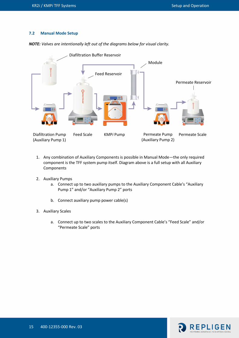
7.2 Manual Mode Setup NOTE: Valves are intentionally left out of the diagrams below for visual clarity.
1. Any combination of Auxiliary Components is possible in Manual Mode—the only required component is the TFF system pump itself. Diagram above is a full setup with all Auxiliary Components
2. Auxiliary Pumps a. Connect up to two auxiliary pumps to the Auxiliary Component Cable’s “Auxiliary
Pump 1” and/or “Auxiliary Pump 2” ports
b. Connect auxiliary pump power cable(s)
3. Auxiliary Scales
a. Connect up to two scales to the Auxiliary Component Cable’s “Feed Scale” and/or “Permeate Scale” ports
Feed Scale Permeate Pump (Auxiliary Pump 2)
Permeate Scale
Diafiltration Buffer Reservoir
Module
Permeate Reservoir
Feed Reservoir
Diafiltration Pump (Auxiliary Pump 1)
KMPi Pump

16 400-12355-000 Rev. 03
KR2i / KMPi TFF Systems Setup and Operation
7.3 C. Mode Setup
1. Auxiliary Pumps
a. (Optional) To control permeate rate, connect auxiliary pump to the Auxiliary Component Cable’s “Auxiliary Pump 2” port
b. (Optional) Connect Auxiliary Pump 2's power cable
2. Auxiliary Scales
a. Connect scale to the Auxiliary Component Cable’s “Permeate Scale” 7.4 C/D and C/D/C Mode Setup NOTE: Permeate Pump is optional and shown in the diagram as an example for applications that require permeate control.
1. Auxiliary Pumps
Feed Reservoir
KMPi Pump
Permeate Reservoir
Diafiltration Buffer Reservoir Module
Diafiltration Pump (Auxiliary Pump 1)
Feed Scale
Permeate Reservoir
Permeate Pump (Auxiliary Pump 2)
Permeate Scale
Module
KMPi Pump Feed Reservoir Permeate Scale

17 400-12355-000 Rev. 03
KR2i / KMPi TFF Systems Setup and Operation
a. Connect auxiliary pump to the Auxiliary Component Cable’s “Auxiliary Pump 1” port and second auxiliary pump to the Auxiliary Component Cable's "Auxiliary Pump 2" port
b. Connect Auxiliary pump power cables(s)
2. Auxiliary Scales
a. Connect first scale to the Auxiliary Component Cable’s “Feed Scale” port and second
scale to the Auxiliary Component Cable’s “Permeate Scale” port 7.5 C/D/D/C Mode Setup
1. Auxiliary Pumps
a. Connect first auxiliary pump to the Auxiliary Component Cable’s “Auxiliary Pump 1” port and second auxiliary pump to the Auxiliary Component Cable’s “Auxiliary Pump 2” port
b. Connect auxiliary power cables c. Auxiliary Pump 1 will function as Diafiltration Pump 1, and the Auxiliary Pump 2
will function as Diafiltration Pump 2
2. Auxiliary Scales
a. Connect first scale to the Auxiliary Component Cable’s “Feed Scale” port and second scale to the Auxiliary Component Cable’s “Permeate Scale” port
Diafiltration Buffer Reservoir 1 Module
Permeate Reservoir
Diafiltration Buffer Reservoir 2
Feed Reservoir
KMPi Pump Feed Scale Permeate Scale Diafiltration Pump (Auxiliary Pump 1)
Diafiltration Pump (Auxiliary Pump 2)

18 400-12355-000 Rev. 03
KR2i / KMPi TFF Systems Setup and Operation
7.6 CFC Mode Setup NOTE: Permeate Pump is optional and shown in the diagram as an example for applications that require permeate control.
1. Auxiliary Pumps
a. Connect auxiliary pump to the Auxiliary Component Cable's "Auxiliary Pump 1" port and second auxiliary pump to the Auxiliary Component Cable's "Auxiliary Pump 2" port
b. Connect auxiliary pump power cables
c. The Auxiliary Pump 1 will function as Constant Feed Pump
2. Auxiliary Scales
a. Connect first scale to the Auxiliary Component Cable’s “Feed Scale” port and second scale to the Auxiliary Component Cable’s “Permeate Scale” port
Extra Feed Reservoir Module
Feed Reservoir
Permeate Reservoir
Diafiltration Pump (Auxiliary Pump 1)
KMPi Pump Permeate Pump (Auxiliary Pump 2)
Permeate Scale Feed Scale

19 400-12355-000 Rev. 03
KR2i / KMPi TFF Systems Setup and Operation
7.7 CF/D/C Mode Setup
1. Auxiliary Pumps
a. Connect auxiliary pump to the Auxiliary Component Cable's "Auxiliary Pump 1" port
and second auxiliary pump to the Auxiliary Component Cable's "Auxiliary Pump 2" port
b. Connect auxiliary pump power cables
c. Auxiliary Pump 1 will function as Constant Feed Pump, and Auxiliary Pump 2 will
function as Diafiltration Pump
2. Auxiliary Scales
a. Connect first scale to the Auxiliary Component Cable’s “Feed Scale” port and second scale to the Auxiliary Component Cable’s “Permeate Scale” port
KMPi Pump
Diafiltration Pump (Auxiliary Pump 2)
Feed Scale
Diafiltration Buffer Reservoir
Permeate Scale Constant Feed Pump (Auxiliary Pump 1)
Extra Feed Reservoir
Permeate Reservoir
Feed Reservoir Module

20 400-12355-000 Rev. 03
KR2i / KMPi TFF Systems Setup and Operation
7.8 Ctrl Mode NOTE: Refer to section 8.2.1.7 and 8.3 for further information about Ctrl Mode.
1. Auxiliary Pumps
a. Connect auxiliary pump (optional permeate pump) to the Auxiliary Component Cable’s “Auxiliary Pump 2” port
d. Connect auxiliary pump power cables
2. Auxiliary Scales
a. Connect first scale to the Auxiliary Component Cable’s “Feed Scale” port and second scale to the Auxiliary Component Cable’s “Permeate Scale” port
7.9 System Setup Using KF Comm Pump Control Window 7.9.1 KF Comm User Interface
The Pump Control Interface can be used to interact with all the features of the system. This screen will appear when the KF Comm software is opened in Excel. When needed, the functions and setpoints are accessible on the main pump display. For full explanation of Pump Control window please refer to section 8.1 KF COMM Pump Control User Interface. Below is the basic layout of the Pump Control window:
Feed Reservoir
KMPi Pump
Permeate Reservoir
Diafiltration Buffer Reservoir Module
Feed Scale Permeate Pump (Auxiliary Pump)
Permeate Scale

21 400-12355-000 Rev. 03
KR2i / KMPi TFF Systems Setup and Operation
Gear icons bring up mini menus for each respective section.
Figure 1A: Modify Set-Points view of Pump Control
Start
Stop
Emergency Valve Open
Records process time once pump starts. Does not record when pump is paused, and resets when the pump is stopped then runs a new process.
After ”Start” is pressed, the step that the Pump Mode is actively on will fill. Once it is done, the next step will fill.
Visible but disabled when the valve is not pinching. Only available to click when valves are pinching.
If “Safe” is checked, “Edit” buttons and “Tare” buttons will be disabled. Reference Calculator can still be opened.
Arrow slides the “Live Values and Settings” window shut.
Switches to “Overview” view.
Engaging the numeric valve input box brings up a floating keypad mini menu that can optionally be used to input the numbers instead of typing it in from the keyboard.
Valves can be started and stopped freely in M Mode and will have a green start button that changes to a red start button when pressed (pressing “Start” when Valve is set to “Manual” will bring up the current Valve open/close Mini Menu).

22 400-12355-000 Rev. 03
KR2i / KMPi TFF Systems Setup and Operation
Figure 1B: Overview view of Pump Control Main Pump: Set and display pump drive's flow rate, pump direction, current Pump Mode, and Ramp Rate. Auxiliary Pump 1: Display Auxiliary Pump 1 flow rate. Can only set Auxiliary Pump 1 flow rate in Manual mode. Auxiliary Pump 2: Set and display Auxiliary Pump 2 flow rate. Can not be set in C/D/D/C and CF/D/C Mode, as the Auxiliary Pump 2 operates as a Diafiltration Pump in those two modes. Pressure/Valve: Set and display target psi/bar and also set Auto or Manual mode. Can manually set pinch distance in Manual Mode. Dialog box also displays current pressure readings from pressure transducers. Pressure sensors can also be tared. Alarms: Set and display alarms and stops. Safe Checkboxes: Checking the “safe” checkbox disables changing values. Reference Calculator: The Reference Calculator allows the user to run calculations for Pump Modes to estimate the volumes of solution that will be moved through the flowpath from the beginning to end of a Pump Mode application.
Switches to “Set Points” view.
While Function runs, the process bar fills up to show progress. The slider moves as the bar fills, and the number above updates with the current concentration/diafiltration value (see example below).
Similar to the Progress Bar, the live value’s position (as indicated by a thick grey slightly longer line) on the alarm bars will adjust to show levels. The position of the bar will show the user how close the live value is to a high stop (thick red line), high alarm (thin red line), low stop (thick blue line), and low alarm (thin blue line). When the alarm is raised, the window on the right is shown.

23 400-12355-000 Rev. 03
KR2i / KMPi TFF Systems Setup and Operation
Status Bar: Upper portion of Pump Control that allows user to view elapsed running time and current Pump Mode. The user can also Start/Pause/Stop the Pump, and Open all Valves from the Status Bar. Live Values and Options: Middle portion of Pump Control that displays numeric readings of all major TFF System assets. Each asset has an applicable Settings menu accessed from its gear icon. The user can also configure Alarms, KF Comm Data Collection, and TFF System Hardware Options along with open the Reference Calculator. The user may also Save/Load KF Comm parameters. Live Values and Options segment can be hidden/unhidden by clicking on its tray slider arrow. Process Parameters: Lower portion of Pump Control that allows user to input set-points (in Modify Set-Points view) or monitor the application (in Overview view). View can be changed by clicking on Modify Set-Points / Overview button. Progress Bar displays starting value on left-hand side, and target set-point on right-hand side. The Progress Bar will fill as the Pump Mode runs. The Safety Alarm bars will display different bands of color depending on what alarms have been set for an auxiliary component. Process Parameters segment can be hidden/unhidden by clicking on its tray slider arrow. Safety Alarm Bar Indicators Thick Red Band High Alarm Stop Thin Red Band High Alarm Grey Band Current value (position relative to alarms values) Thick Blue Band Low Alarm Stop Thin Blue Band Low Alarm If an alarm is raised, the alarm can be acknowledged either by pressing “OK” on the alarm dialogue or pressing the “Alarm Off” TFF System pump itself.
7.9.2 Entering System Settings
All system settings can be entered using the KF Comm Pump Control window or the pump console display. When using the Pump Control Window the settings can be accessed through the Gear icons
in the different sections.

24 400-12355-000 Rev. 03
KR2i / KMPi TFF Systems Setup and Operation
1. Main Pump
Tubing Size: Select the tubing size used through the pump head. Standard Masterflex® tubing sizes for both the KR2i and KMPi sized pumps are used. Ramp Rate: Enter the ramp rate of the recirculation pump up to 15 sec. Slow for Valve: If turned on the system will automatically reduce the pump speed when pressure buildup continues to increase and the valve is fully open. This feature is typically used when concentrating high viscosity samples. Select from 1-10% reduction in pump speed at either %/min or %/sec. Control Shear: If turned on the system will maintain recirculation pump speed based on retentate shear rate/flow rate. The Flowrate display in the Main Pump section will then be based on retentate not feed flow. 2. Aux Pump
Aux Pump 1, Aux Pump 2: Select the tubing size and the type of pump There are three types of possible Auxiliary Pumps: 300 RPM – KR Jr 600 RPM – KR1 650 RPM – I/P Pump (only for KMPi)
NOTE: Auxiliary Pump settings must be correctly input for KR2i system to function properly. Tubing sizes are standard Masterflex® tubing sizes and the possible tubing sizes for the selected Aux Pump will appear in the drop down list.

25 400-12355-000 Rev. 03
KR2i / KMPi TFF Systems Setup and Operation
3. Pressure/Valve
Pressure Unit: Either psi or bar
NOTE: Green highlighted boxes are currently selected.
Valve: Enter both Valve 1 and Valve 2 (for KMPi) settings. Valve Mode: Select to control Valve Manually or Automatically (see section 10.3.3). Tubing Size: Select the tubing size that goes through the backpressure valve. Control: Select the pressure control location (Feed, Permeate, Retentate, or TMP). Starting Position: Select the starting position for automated control from following options:
1. Open – no pinching of tubing
2. Half – 50% closed based on selected tubing size in valve
3. Custom – pinches the tubing based on the Custom Start Position value Valve Size: select either the KR2i Valve (tubing up to 5/8” OD) or the KMPi Valve (tubing up to ¾” OD)

26 400-12355-000 Rev. 03
KR2i / KMPi TFF Systems Setup and Operation
4. Alarms
Silent Alarm: Turn on to silence the alarm inside the pump console. PC Silent Alarm: Turn on silence the alarm from the PC; Test confirms the PC alarm is working. Pressure and Scale: Activate and input the setpoint for the various warnings and interlocks. Please refer to Section 7.12 for further definitions.
NOTE: When the ‘Overview’ option is selected for the bottom portion of the Pump Control window, the alarm values will have thin lines indicating warning level and thicker lines to signal stop.
Find Comm: Select to automatically find the USB Com port assigned to the TFF system. About: KF Comm Version information. Apply: Current selections updated. Hardware: Hardware Setup window appears.

27 400-12355-000 Rev. 03
KR2i / KMPi TFF Systems Setup and Operation
5. Hardware Setup
Settings for the Automation Modes and general system parameters are entered into the Hardware Setup window.
NOTE: All hardware settings and other options can be entered in the system console under the wrench icon. Please refer to section 7.10.5. The Feed and Permeate Status and Hold-up Volumes can be entered in the Pump Mode screen on the console.
Feed and Permeate Status and Hold-up: volumes not currently measured on the scale are back-calculated into the formula for endpoint control based on Concentration Factor and Diafiltration Volumes. Feed Status: Select ‘Empty’ if recirculation loop is empty upon start of automated process. Select ‘Full’ if recirculation loop is full of liquid. Permeate Status: Select ‘Empty’ if permeate side of the filter and permeate tubing is empty upon start of automated process. Select ‘Full’ if permeate side of the filter and permeate tubing is full of liquid. Feed Hold-up: measure the amount of liquid in the feed holdup and enter the amount. Volume can be measure by starting with an empty flowpath, closing the permeate line and measuring the amount of liquid in the reservoir before and after running the system. The difference in the amount of liquid is the recirculation holdup volume. Permeate Hold-up: measure the amount of liquid in the permeate side of the filter plus the permeate tubing and enter the amount. Permeate Stop First: Permeate pump drive stops before main drive stops Check Weight: Automated pump mode will not start if Feed Scale Weight is less than Initial Concentration Weight, or if the Permeate Scale Weight is more than the Initial Diafiltration Weight.

28 400-12355-000 Rev. 03
KR2i / KMPi TFF Systems Setup and Operation
Scale Required for Manual: Manual Mode will not start unless both Feed and Permeate Scales are present. Valve 2 (For KMPi Only): Select either if Valve 2 port is being used with Automatic backpressure valve or with KONDUiT Diafiltration and Concentration 1 and 2: Select the control mechanism for the automated mode setpoints. The numbering scheme for concentration and diafiltration is sequential during the automated mode. For Example - Concentration 1 is the initial concentration as in the example below for CDDC mode and the other modes are sequential:
6. Automated Mode Control Strategy
End point settings for concentration and diafiltration can be selected to be either by weight (CF and DV) or, with the KONDUiT accessory, to be UV or Conductivity. Below are explanations and example applications for different control strategies:
Diafiltration 1 Set Point: 1. DV (Diafiltration Volumes)
a. End-point control when permeate scale reaches target DV based on weight of feed
scale and holdup loop
b. Example Application: diafiltration of virus or protein
2. Cond 1
a. End-point control when conductivity reaches setpoint of Conductivity Sensor 1
b. Example Application: diafiltration of protein or oligo
3. UV
a. Semi-quantitative end-point control when UV reaches target AU
b. Example Application: diafiltration of latex particle with free IgG measurement on permeate; offline confirmation needed for verification
Concentration 1 Diafiltration 1
Diafiltration 2 Concentration 2

29 400-12355-000 Rev. 03
KR2i / KMPi TFF Systems Setup and Operation
Diafiltration 2 Set Point (Diaf 2 used in CDDC mode for second wash buffer):
1. DV (Diafiltration Volumes)
a. End-point control when permeate scale reaches target DV based on weight of feed scale and holdup loop
b. Example Application: diafiltration of virus or protein
2. Cond 1
a. End-point control when conductivity reaches setpoint of Conductivity Sensor 1
b. Example Application: diafiltration of protein or oligo
3. UV
a. Semi-quantitative end-point control when UV reaches target AU
b. Example Application: diafiltration of latex particle with free IgG measurement on permeate; offline confirmation needed for verification
Concentration 1 Set Point:
1. CF (Concentration Factor)
a. End-point control when retentate and permeate scale reaches target CF based on weight of feed scale and holdup loop
b. Example Application: concentration of virus or protein
2. UV
a. Semi-quantitative end-point control when UV reaches target AU, Application dependent, offline confirmation needed for verification
b. Example Application: concentration of oligo
3. UV2
1. Semi-quantitative end-point control when UV reaches target AU, Application dependent, offline confirmation needed for verification
2. Example Application: concentration of oligo Concentration 2 Set Point (Conc 2 used for final concentration in CDC):
1. CF (Concentration Factor)

30 400-12355-000 Rev. 03
KR2i / KMPi TFF Systems Setup and Operation
a. End-point control when retentate and permeate scale reaches target CF based on weight of feed scale and holdup loop
b. Example Application: concentration of virus or protein
2. UV
a. Semi-quantitative end-point control when UV reaches target AU; Application dependent, offline confirmation needed for verification
b. Example Application: concentration of oligo Here is an example of Hardware Setup once a system is connected. NOTE: Green highlighted boxes are currently selected.
7.10 Using Pump Interface The system settings accessed through the Pump Control Window mentioned in Section 7.9 above can also be accessed directly on the pump console. The TFF system’s easy-to-use keypad allows the user to navigate through the LCD Home Screen to utilize the many convenient functionalities it offers. 7.10.1 Keypad
a. LCD Screen – Digital, high-contrast LCD screen that allows user to interface with the TFF system

31 400-12355-000 Rev. 03
KR2i / KMPi TFF Systems Setup and Operation
b. Directional Arrows – Navigate throughout menu items by highlighting with directional arrows
c. Enter – Select highlighted menu items and input information d. Start/Pause – Start/Pause main pump from any menu e. Tare/Alarm Acknowledgement – When held down, will tare pressure transducer values—
during an alarm, will acknowledge alarm 7.10.2 Main Screen
a. Current Pump Mode – Formatted as “Spectrum: (Pump Mode),” allows user to see the current Pump Mode the TFF system is in
b. Pressure Readings – The current values read by any connected Pressure Transducers.
Preferred unit of measurement can be selected in Hardware Setup
i. Feed Pressure – Symbolized as Pf
ii. Permeate Pressure – Symbolized as Pp
iii. Retentate Pressure – Symbolized as Pr
iv. TMP (Transmembrane Pressure) – Calculated measurement of the average of the Feed and Retentate pressures subtracted by the Permeate pressure
NOTE: Please take care to understand the following in regards to how pressure transducers are read by the system: When the TFF system is turned on and no pressure transducer has been plugged Into a port, the empty pressure transducer port will display dashes as readings. When the TFF system is turned on and a pressure transducer has been plugged into a port, the occupied pressure transducer port will display a value. When the TFF system is turned on, a pressure transducer is connected, and then the pressure transducer is disconnected or becomes faulty, the port will display stars. TMP calculations assume that if a pressure transducer is not connected or faulty then the reading is 0. If the pressure sensors are plugged in after the system is on then there will be an offset of ~14.5 psi (1 bar). Before starting the process tare the pressure sensors to zero by holding down the Alarm Off button for 3 seconds
c. Settings Menu – Symbolized as a wrench icon; entering this menu allows the user to change the TFF system's settings
d. Pump Direction – Represented by an arrow that denotes whether the pump turns Clockwise
(CW) or Counterclockwise (CCW)—pressing Enter on this icon will change the pump direction
e. Tubing Selection Menu – Represented by a number (the current selected tubing size) and a
small “c” (only when current selected tubing size has been calibrated); entering this menu allows the user to change the tubing selection or set pump to RPM mode (can not be calibrated)

32 400-12355-000 Rev. 03
KR2i / KMPi TFF Systems Setup and Operation
f. Feed Flow Rate – Main drive’s flow rate
g. Pump Mode Resume Icon – When a Pump Mode other than Manual Mode is paused with
the Start/Pause key, the Pump Mode can be resumed by pressing the Enter key while highlighting the Pump Mode Resume icon. If the user wishes to restart the Pump Mode instead, the user can press the Start/Pause key
h. Valve Control Icons – When Automatic Backpressure Valves are connected and powered,
the user will be able to access the Valve Control icons to open, close, and configure the Automatic Backpressure Valves (see Section 7.10.3 Remote Control of Auxiliary Pumps and Valves for details)
i. Auxiliary Pump Control Icons – When Auxiliary Pumps are connected, powered on, and
configured correctly, the user will be able to access the Auxiliary Pump Control Icons to release, capture, start, pause, and change the flow rate of Auxiliary Pumps (see Section 7.10.3 Remote Control of Auxiliary Pumps and Valves for details)
j. Pump Mode Status Timeout Display – When Auxiliary Scales or KF KONDUiT are connected and powered on, the user will be able to view the Pump Mode Status Timeout Display. The Timeout Display will show weight and Conductivity/Temperature/UV (when using KONDUiT) information related to the current Pump Mode if the user highlights the double arrow button and does not touch the pump for a few seconds (see Section 8.4 for Timeout Display details)
7.10.3 Remote Control Of Auxiliary Pumps and Valves
Auxiliary Pump Control Icons When on the lower half of the main screen’s side bar with both Auxiliary Pumps connected, two arrow icons with the numbers "1" and "2" under them will be visible and accessible. These arrow icons are the Auxiliary Pump Control Icons. The "1" arrow controls Auxiliary Pump 1, while the "2" arrow controls Auxiliary Pump 2.
Valve 1 Control Icon
Pump Mode Resume Icon
Auxiliary Pump 1 Resume Control Icon

33 400-12355-000 Rev. 03
KR2i / KMPi TFF Systems Setup and Operation
1. Press the Enter key on a highlighted Control Icon to set the flow rate of the selected pump in ml/min using the Directional Arrow soft buttons
2. Press Enter again to exit the Auxiliary Pump flow rate screen
3. When a Pump Mode is not running, the user may release and capture control of the
Auxiliary Pumps
a. Highlight the Captured Pump (represented by a solid line arrow graphic) and press the left soft button
b. The arrow icon will then change to a disjointed arrow graphic, signifying that the
Captured Pump is now a Released Pump
c. When released, the TFF system will stop sending signals to the Released Pump. The Auxiliary Pump can then be switched from External to Internal mode and used as a standalone pump, instead of being controlled by the TFF system
NOTE: While Auxiliary Pump is in Internal mode, the Flow Direction of the Auxiliary Pump can be changed. However, once switched back to External Mode and recaptured, the Auxiliary Pump will only pump in a Clockwise Flow Direction. Auxiliary Pump Flow Direction is always Clockwise when part of the TFF system.
4. A Released Pump can also be re-captured
a. First, stop any running Pump Modes
b. Highlight the target Released Pump and press the left soft button
c. The arrow icon will then change back to a solid line arrow graphic
d. Highlight the target Released Pump and press the left soft button
5. When an Auxiliary Pump is running due to a Pump Mode, the solid line arrow graphic will become an animated arrow graphic
a. To start or stop the Permeate Pump during a Pump Mode using the Auxiliary Pump
Control Icon, highlight the Permeate Pump Control Icon and then press the right soft button
Pump 1 Captured Pump 1 Released Pump 1 Running, Animated

34 400-12355-000 Rev. 03
KR2i / KMPi TFF Systems Setup and Operation
Valve Control Icons When on the upper half of the main screen's side bar and one (for the KR2i) or two (for the KMPi) Automatic Backpressure Valves (style of valve-- SmartValve or Classic-- does not matter, however box-style Automatic Backpressure Valve must be from 2015 or newer) connected, one (for the KR2i) or two (for the KMPi) valve icons with the numbers "1" and "2" above them will be visible and accessible. These icons are the Valve Control icons. NOTE: When valves are pinching, at anytime other than when manually setting pinch distance the user may open all valves by holding down the right arrow key.
1. Press the Enter key on a highlighted Control icon to enter Valve mini menu and edit Valve
configurations
2. Navigate to Exit and press Enter to exit the Valve mini menu
3. Press the right arrow on the highlighted Control icon to start pinching. If on Manual mode, hold down either the left or right arrow afterwards to manually adjust the pinch distance. Pressing/holding the left arrow will decrease pinch distance, while pressing/holding the right arrow will increase pinch distance. When satisfied with manually set pinch distance, user may press Enter to tell valve to hold that position
4. To open valve, user can press the right arrow key on the highlighted Control icon NOTE: Auxiliary Pump 1 cannot be started or stopped during C/D/D/C Mode, because it is functioning as Diafiltration Pump 2. Auxiliary Pump 1 also cannot be started or stopped during CF/D/C Mode, because it is functioning as a Diafiltration Pump. Similarly, Auxiliary Pump 1 cannot be started or stopped in the same manner as Auxiliary Pump 2 during any running Pump Modes other than Manual Mode.
Valve 1 Manual Open Valve 1 Manual Pinch
Valve 1 Auto Open Valve 1 Auto Pinch

35 400-12355-000 Rev. 03
KR2i / KMPi TFF Systems Setup and Operation
7.10.4 System Settings
a. Pump Mode – Depending on user’s Auxiliary Components, user may select one of many Pump Modes for the TFF system to operate in that allow for manual, semi-automated, and automated processes
b. Pressure Calibrate – Using a calibrated pressure source, the user can calibrate pressure
transducer readings
c. Alarm and Stops – Safety pressure, weight and UV alarms and interlocks
d. ABV Settings - TFF system's valve settings must be configured prior to using the valves (see Section 10.3.3 for details)
e. Tubing Calibrate – After running the tubing in the pump for ten minutes, the user may calibrate the tubing to ensure accurate fluid dispensing; tubing can not be calibrated if pump is set to display RPM
f. Aux Pumps – TFF system’s Aux Pump settings must be configured prior to using the Auxiliary
Pumps to ensure the TFF system sends the correct commands to each pump
g. Hardware Setup – Time, date, unit of measure, and some Pump Mode options may be set from the Hardware Setup menu described in more detail in the next section
h. Diagnostics – Diagnostics are for the factory use only, but may be viewed by the user
7.10.5 Hardware Setup
a. Auto Tare – When “On,” TFF system will tare pressure transducer readings
b. Pressure Units – User is able to choose “psi” or “bar” (selected unit of measure is also displayed in KF Comm software)
c. Time – Change system time
d. Date – Change system date
e. Key Beep – When “On,” the TFF system will make an audible noise when a soft button is
pressed
f. Display Contrast – Raise or lower the screen contrast

36 400-12355-000 Rev. 03
KR2i / KMPi TFF Systems Setup and Operation
g. PSI Decimals – For PSI unit of measure only—select preferred number of PSI decimals (range of 0, 1, and 2)
h. Bar Decimals – For BAR unit of measure only—select preferred number of BAR decimals
(range of 1, 2, and 3)
i. Key Timeout – When “On,” if the TFF system’s soft buttons are untouched for ten minutes while on any screen other than the Main Screen, the TFF system will automatically switch back to the Main Screen
j. Running Change – When “On,” the tubing size and pump direction can be changed while the pump is running
k. No. of Heads – Input number of attached pump heads
l. Perm Stop First - Permeate Pump motor stops before main drive stops
m. Check Weight - Pump Mode will not start if Feed Scale Weight is less than Initial
Concentration Weight, or if the Permeate Scale Weight is more than the Initial Diafiltration Weight
n. Scale Req 4 Man - Manual Mode will not start unless both Feed and Permeate Scales are
present
o. Slow for Valve - If Automatic Backpressure Valve is unable to control pressure, then main drive will slow down gradually to control pressure increases especially when concentrating viscous solutions
p. Ramp Seconds - Determines rate at which TFF system will increase main pump flow rate
linearly over desired amount of time
q. Minus Modes – Enables TFF system to use weight set-points instead of CF/DV setpoints. Once turned on KF Comm needs to be closed and reopened to have access to these modes in the Pump Control Window.
r. Valve 2 - (on KMPi only) Select either 'Valve 2 Port' if using a secondary automatic backpressure valve or 'KONDUiT' if using the conductivity, temperature and UV sensors
NOTE: when connecting a KONDUiT to the Valve 2 serial connection use the null serial connector included with the KONDUiT.
s. Shear Control – When set to Off, after initial ramp rate the pump drive will run continuously
at set flow rate. When set to On, TFF system will increase main pump flow rate depending on feedback from Permeate Scale to make up for permeated volume (e.g. Permeate Scale read weights as increasing at ~200g/min, main pump flow rate will increase by 200ml/min)
t. Cond 1 K and Cond 2 K - enter the K factor printed on the conductivity sensor when using the KONDUiT

37 400-12355-000 Rev. 03
KR2i / KMPi TFF Systems Setup and Operation
7.11 Pressure Calibrate
1. Ensure proper connection between a set of new pressure transducers and Octopus Cable ports, then tare pressure readings
2. Turn on positive air source from a calibrated pressure source and adjust to dispense 5 psi /
0.35 bar of pressure, then turn positive air source off
3. Connect Feed pressure transducer to be in-line with positive air source—cap the remaining open end of the pressure transducer
4. Turn on positive air source
5. Wait for Feed pressure reading to stabilize
6. If Feed pressure reading differs from calibrated source measurement, select Pressure
Calibrate from Settings Menu
7. Select source of pressure (in this case, “Feed”), then adjust “Set:” pressure reading to reflect that of calibrated source
8. Save changes by selecting “Cal”
9. Repeat steps 3 to 8 with the Retentate and Permeate ports
7.12 Alarms and Stops The TFF system has a number of safety pressure alarms and stops that may be set in the Alarm Settings menu. a. Pf Hi Stop – When Feed Pressure (Pf) value ≥ Pf Hi Stop value, the pump drive will stop running
b. Pf Hi Alarm – When Pf value ≥ Pf Hi Alarm value, the pump drive will alarm but continue
running
c. Pf Lo Stop – When Pf value ≤ Pf Lo Alarm value, the pump drive will stop running
d. Pf Lo Alarm – When Pf value ≤ Pf Lo Alarm value, the pump drive will alarm but continue running
NOTE: For the Pf Lo Stop and Lo Alarm the feed pressure must first rise above the alarm level to be activated.

38 400-12355-000 Rev. 03
KR2i / KMPi TFF Systems Setup and Operation
e. Pp Lo Alarm – When Permeate Pressure (Pp) value ≤ Pp Lo Alarm value, the pump drive will alarm but continue running
f. Pp Lo Stop – When Pp value ≤ Pp Lo Stop value, the pump drive will stop running
g. UV Hi Stop: When AU value of UV1 is ≥ UV Hi Stop value the system will shut down h. UV Hi Alarm: When AU value of UV1 is ≥ UV Hi Alarm value the pump drive will alarm but
continue running i. Perm Hi Alarm: When permeate scale reading is ≥ Perm Hi Alarm value the system will alarm
but continue running j. Perm Hi Stop: When permeate scale reading is ≥ Perm Hi Stop value the system will shut
down k. Feed Hi Alarm: When feed scale reading is ≥ Feed Hi Alarm value the system will alarm but
continue running
l. Feed Hi Stop: When feed scale reading is ≥ Feed Hi Stop value the system will shut down m. Feed Lo Alarm: When feed scale reading is ≤ Feed Lo Alarm value the system will alarm but
continue running n. Feed Lo Stop: When feed scale reading is ≤ Feed Lo Stop value the system will shut down o. Silent Alarm – Set to “On” to silence alarms, set to “Off” to play alarm sound
1. To enable an alarm, highlight the alarm value and press Enter 2. Use the directional keys to set the desired alarm value, then press Enter to save the
setting 3. To disable an alarm, change the value to 0 and TFF system will read the alarm as
“OFF”
7.13 Tubing Calibration NOTE: Condition tubing by running at ½ of maximum flow rate of tubing being calibrated for at least 10-15 minutes before conducting tubing calibration. Tubing calibration cannot be done when pump is in RPM mode.
1. Select tubing size in Calibration menu
2. Press CAL, the system set calibration volume will appear
3. Press START / STOP, the pump will use its stored memory to dispense the specified
calibration sample quantity. The pump will stop automatically
4. Weigh/measure the sample

39 400-12355-000 Rev. 03
KR2i / KMPi TFF Systems System Functionality
5. Use directional keys to correct the volume on the flashing display
6. Press the Enter key to save the calibration setting. Once calibrated, a lower case "c" appears next to the tubing (e.g. 73c)
7. To confirm tubing calibration, press CHECK to dispense calibration volume using calibrated
tubing and weigh dispensed volume NOTE: If the adjusted calibration is high, "Err" will appear in the display. If this occurs, press the CAL control and repeat the calibration procedure. The microprocessor will retain one special calibration value per tubing size, even when power is turned off. The next calibration will replace the existing value.
System Functionality 8.1 Pump Controls The Pump Control Interface can be used to interact with all the features of the system. This screen will appear when the KF Comm software is opened in Excel. When needed, the functions and setpoints are accessible through the touchpad on the main pump display. See the Pump Control layout in section 7.9.1 KF COMM Pump Control User Interface for further information using the Pump Control Interface on the PC. 8.1.1 Overview
The TFF system alternates through different functions based on user-defined set-points suitable for the user’s application—these combinations of functions are Pump Modes. All Pump Modes are composed of different sequences of Concentration and Diafiltration functions. Refer to Section 12 Basic Concepts of Tangential Flow Filtration.
a. Concentration: Reduce volume of process solution
b. Diafiltration: Wash permeable molecules out of the process solution Auxiliary Components are associated with the following most commonly used automated functions and actions:
c. Feed Scale: Weighs feed reservoir to monitor Concentration and Diafiltration functions
d. Permeate Scale: Weighs permeate reservoir to monitor Concentration and Diafiltration functions
e. Diafiltration Pump: Replenishes loss feed reservoir volume during diafiltration function; usually Auxiliary Pump 1 in most modes
f. Permeate Pump: Controls permeation rate for MF applications; usually Auxiliary Pump 2 in most modes
g. Valve 1: Control TMP, Retentate, Inlet or Permeate Pressure

40 400-12355-000 Rev. 03
KR2i / KMPi TFF Systems System Functionality
h. Valve 2: Control TMP, Retentate, Inlet or Permeate Pressure
i. KONDUiT: If Concentration or Diafiltration Set-point in Hardware Setup is set to Conductivity or UV set-points, then KONDUiT signals when pump mode ends
8.2 Detailed Pump Mode Operation 8.2.1 Concentration Mode
Concentration Mode may be used to flush the module to prepare it for use. For example, some modules must be flushed with 2 ml of water for every cm2 of its surface area. The module in the example below has a surface area of ~0.80 m2, which means the module must be flushed with ~16L of water. To automate flushing the module on the TFF system while only using a Permeate Scale, the user can simply start with 32 kg of water in the Feed Reservoir, input the value into the TFF system as 32L of Feed Hold-up and set Feed Status Empty. Then the user must set the Conc Factor setpoint to 2X. Once 16 kg of water has been moved from the Feed scale to the Permeate Scale, C Mode will end.
Starting Weight 32 kg
Conc Factor 1 2X Perm Wt After C1 16 kg
Feed Wt After C1 16 kg
Feed Scale* Permeate Scale
* Feed Scale is optional in this example to demonstrate how to use Feed Hold-up and Feed Fill options.
Feed Reservoir
KMPi Pump
Permeate Reservoir
Diafiltration Buffer Reservoir Module
Diafiltration Pump (Auxiliary Pump 1)
Feed Scale Permeate Pump (Auxiliary Pump 2)
Permeate Scale

41 400-12355-000 Rev. 03
KR2i / KMPi TFF Systems System Functionality
8.2.2 Concentration/Diafiltration Mode
C/D Mode may be used for a Fed-Batch concentration, followed by a Diafiltration. NOTE: This constant feed concentration followed by a diafiltration can be done with the CDDC mode when 2 auxiliary pumps are available (see Section 8.2.4 below). Also the CD mode can be done without the vacuum addition if the full sample fits in the process vessel on the scale. On the Feed Reservoir with four ports, set-up the ports as described below to create a vacuum that will draw excess feed into the Feed Reservoir from the Extra Feed Reservoir:
1. Feed Line to Filter: Connect tubing from this line through pump head to filter's feed port
2. Retentate Line from Filter: Connect tubing from filter retentate port to this line
3. Buffer: Connect through Auxiliary Pump 1 to Diafiltration Buffer Reservoir
4. Vent: Connect to Extra Feed Reservoir
Feed Reservoir
Module
Permeate Reservoir
Diafiltration Pump (Auxiliary Pump 1)
Feed Scale KMPi Pump Permeate Pump (Auxiliary Pump 2)
Permeate Scale
Extra Feed Reservoir
Diafiltration Buffer Reservoir

42 400-12355-000 Rev. 03
KR2i / KMPi TFF Systems System Functionality
On both the Extra Feed Reservoir and Diafiltration Buffer Reservoir, install a vent. Ensure that Auxiliary Pump 1’s head is closed on the tubing between the Diafiltration Buffer and Feed Reservoir. The result of the setup is that the vacuum will pull the entirety of the Extra Feed Reservoir’s contents as volume is depleted from the Process Reservoir the C function of C/D Mode. Once the contents of the Extra Feed Reservoir are depleted, the vacuum will pull air. After the Concentration set-point is reached (Conc Factor 1), the TFF system will then switch to D mode until the Diafiltration set-point (Dia Volumes 1) is reached. The TFF system will be able to properly calculate the Concentration Factor because it will know that a Fed-Batch Concentration is taking place when the Permeate Scale increases while the Feed Scale weight stays constant.
Starting Weight 20 kg
Conc Factor 1 10X Perm Wt After C1 18 kg
Feed Wt After C1 2 kg
Diaf Volumes 1 7 Diaf Wt 1 14 kg
Perm Wt After D1 32 kg
Feed Scale Permeate Scale
1. Feed Line to filter
3. Buffer Line
4. Vent Line
2. Retentate Line from filter
43 400-12355-000 Rev. 03
KR2i / KMPi TFF Systems System Functionality
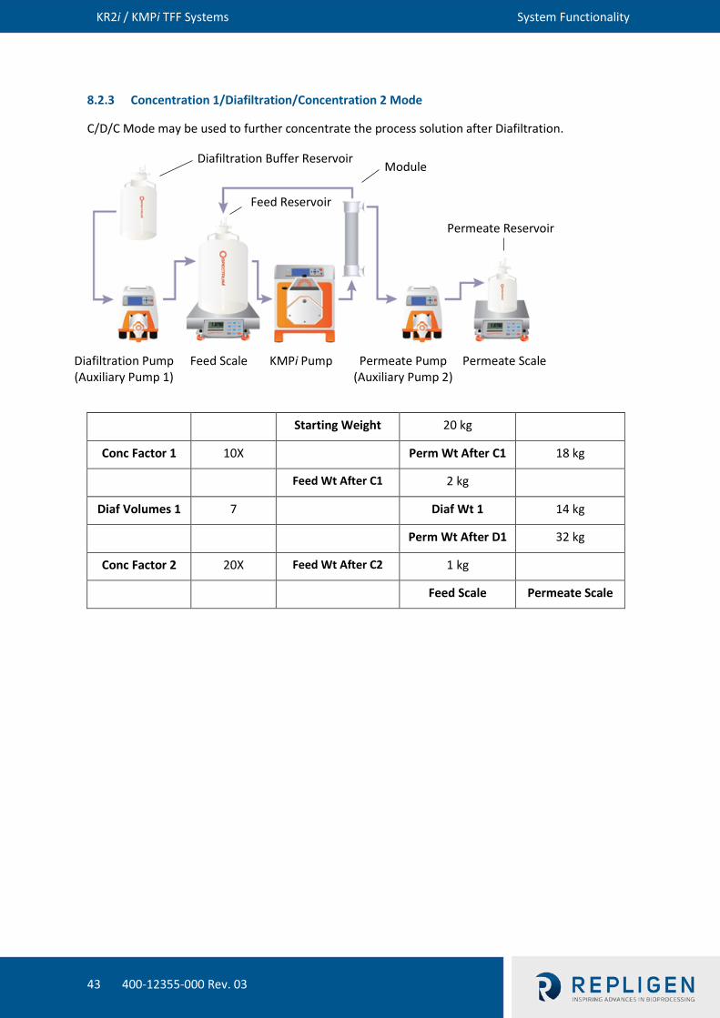
8.2.3 Concentration 1/Diafiltration/Concentration 2 Mode
C/D/C Mode may be used to further concentrate the process solution after Diafiltration.
Starting Weight 20 kg
Conc Factor 1 10X Perm Wt After C1 18 kg
Feed Wt After C1 2 kg
Diaf Volumes 1 7 Diaf Wt 1 14 kg
Perm Wt After D1 32 kg
Conc Factor 2 20X Feed Wt After C2 1 kg
Feed Scale Permeate Scale
Feed Reservoir
KMPi Pump
Permeate Reservoir
Diafiltration Buffer Reservoir Module
Diafiltration Pump (Auxiliary Pump 1)
Feed Scale Permeate Pump (Auxiliary Pump 2)
Permeate Scale

44 400-12355-000 Rev. 03
KR2i / KMPi TFF Systems System Functionality
8.2.4 Concentration 1/Diafiltration 1/Diafiltration 2/Concentration 2 Mode
C/D/D/C Mode may be used to wash the solution with two different buffers.
NOTE: In C/D/D/C Mode Auxiliary Pump 2 functions as Diafiltration Pump 2. For this functionality test, prepare two buffer reservoirs that both lead into the Feed Reservoir, and have one line go through Auxiliary Pump 1 and the other line go through the Auxiliary Pump 2.
Starting Weight 20 kg
Conc Factor 1 10X Perm Wt After C1 18 kg
Feed Wt After C1 2 kg
Diaf Volumes 1 7 Diaf Wt 1 14 kg
Perm Wt After D1 32 kg
Diaf Volumes 2 8 Diaf Wt 2 16 kg
Perm Wt After D2 48 kg
Conc Factor 2 20X Feed Wt After C2 1 kg
Feed Scale Permeate Scale
Diafiltration Buffer Reservoir 1 Module Diafiltration Buffer Reservoir 1
Feed Scale KMPi Pump Diafiltration Pump 2 (Auxiliary Pump 2)
Permeate Scale Diafiltration Pump (Auxiliary Pump 1)
Feed Reservoir
Permeate Reservoir

45 400-12355-000 Rev. 03
KR2i / KMPi TFF Systems System Functionality
8.2.5 Constant Feed Concentration Mode
C/F/C Mode may be used to concentrate a sample that does not fit into the process reservoir.
NOTE: In CFC Mode Auxiliary Pump 1 adds additional sample into the process reservoir. User can select the end point condition to either deplete the Extra Feed Reservoir completely or stop the Aux Pump 1 at a Concentration Factor setpoint. NOTE: If the depletion of the Extra Feed Reservoir is selected, CF might exceed setpoint. NOTE: Aux Pump 1 will stop running once the feed scale detects no additional sample added.
Extra Feed 20L Starting Weight 20 kg
Conc Factor 1 10X Perm Wt After C1 36 kg
Feed Wt After C1 4 kg
Feed Reservoir
Module
Permeate Reservoir
Permeate Pump (Auxiliary Pump 2)
Optional
Extra Feed Reservoir
Constant Feed Pump (Auxiliary Pump 1)
Feed Scale KMPi Pump Permeate Scale

46 400-12355-000 Rev. 03
KR2i / KMPi TFF Systems System Functionality
8.2.6 Constant Feed/Diafiltration/Concentration Mode
CF/D/C Mode may be used to further concentrate the process solution after Diafiltration.
NOTE: User can select the end point condition to either deplete the Extra Feed Reservoir completely or stop the Aux Pump 1 at a Concentration Factor setpoint. NOTE: If the depletion of the Extra Feed Reservoir is selected, CF might exceed setpoint. NOTE: Aux Pump 1 will stop running once the feed scale detects no additional sample added.
Extra Feed 10L Starting Weight 20 kg
Conc Factor 1 10X Perm Wt After C1 27 kg
Feed Wt After C1 3 kg
Diaf Volumes 1 7 Diaf Wt 1 21 kg
Perm Wt After D1 48 kg
Conc Factor 2 20X Feed Wt After C2 1.5 kg
Feed Scale Permeate Scale
Feed Scale
Diafiltration Buffer Reservoir
Permeate Scale Constant Feed Pump (Auxiliary Pump 1)
Extra Feed Reservoir
Module
Permeate Reservoir
KMPi Pump
Feed Reservoir
Diafiltration Pump (Auxiliary Pump 2)

47 400-12355-000 Rev. 03
KR2i / KMPi TFF Systems System Functionality
8.2.7 Ctrl Mode
Ctrl Mode is used when no Aux Pump 1 is available and additional buffer or sample is pulled into the sealed process reservoir by vacuum. Please refer to section 8.2.2 how to setup the reservoir to pull the vacuum. This is called "Control Mode" because the user can tell the KF Comm software when the concentration ends and diafiltration begins instead of being done in auto mode. Please see section below for further explanation.
In Control Mode, the user can manually tell the pump when their flowpath is routed to run in a Concentration or Diafiltration configuration. The Data Collection and calculations on KF Comm will reflect which of the two functions is running until either the “Permeate Weight Stop” set-point is reached or the user presses “Stop” on the Pump or Pump Control. Control Mode can only be accessed properly using KF Comm on a computer.
KMPi Pump
Permeate Reservoir
Diafiltration Buffer Reservoir
Feed Scale (Vacuum generated in sealed vessel)
Permeate Pump (Auxiliary Pump)
Permeate Scale
Feed Reservoir
Module
Control Mode Starting Dialogue appears when “Start” is pressed on Pump Control when Pump Mode is set to “Cntrl Mode”.
After Control Mode starts, the user can switch between the two functions to update KF Comm’s calculations to suit the selected function. Control Mode will stop when either “Permeate Weight Stop” set-point is reached, or user surpasses “Stop” on Pump or Pump Control.

48 400-12355-000 Rev. 03
KR2i / KMPi TFF Systems System Functionality
NOTE: In CFC and CF/D/C mode, there is a Constant Feed Concentration step (the name "CFC" is shortened to "CF" due to character constraints for "CF/D/C" mode). The CFC function is a modified Concentration function. During the CFC step of the two Pump Modes, Auxiliary Pump 1 is used as a Constant Feed Pump that pumps Extra Feed Volume from the Extra Feed Reservoir to the Feed Reservoir. The flow rate of the Constant Feed Pump adjusts to maintain the starting weight on the Feed Scale-- it will continue doing this until the end of the Constant Feed Concentration step. The Constant Feed Concentration step ends when the desired Concentration Factor set-point has been achieved. The CFC function is useful for when a vacuum can not be created between the Extra Feed Reservoir and Feed Reservoir. 8.3 Running the TFF System
Prior to running application, set Hardware (see Section 7.9.2 #5 for Hardware Setup details) and Auxiliary Pump configurations through either the TFF system (see Section 7.9.2 for Auxiliary Pump Settings) or KF Comm Pump Control (see Section 7.10.4 for Pump Control)
1. Set the flow rate of the TFF system in the Main Screen
2. Select a Pump Mode suitable for application (see Section 12.4 for Sample Applications)
3. Input set-points required for the Pump Mode
4. Press the Start/Pause soft button on the TFF system to start Pump Mode or the green
"START" button on top line of Pump Control window. When each set-point is reached during functions, Pump Mode will seamlessly continue to next function until the Pump Mode’s set of functions are completed. Pump Mode will then end automatically.
a. M Mode: Manual Mode
b. C Mode: Concentration Mode
c. C/D Mode: Concentration/Diafiltration Mode
d. C/D/C Mode: Concentration 1/Diafiltration/Concentration 2 Mode
e. C/D/D/C Mode: Concentration 1/Diafiltration 1/Diafiltration 2/ Concentration 2 Mode
f. CFC Mode: Constant Feed Concentration Mode
g. CF/D/C Mode: Constant Feed/Diafiltration/Concentration Mode
h. (KF Comm Only) Ctrl Mode: Control Mode 8.4 Pump Mode Status Timeout Display Use the Pump Mode Status Timeout display to monitor Pump Mode progress. Depending on the Pump Mode, the Timeout display will either show scale weight values, Concentration Factor/Diafiltration Volumes (CF/DV), or KONDUiT readings when attached. Manual Mode will always show scale weight values.

49 400-12355-000 Rev. 03
KR2i / KMPi TFF Systems Pump Head Setup and Operation
a. Manual Mode/Before Running Pump Mode:
i. First Line: Current Feed Scale weight (preceded by “F:”)
ii. Second Line: Current Permeate Scale weight (preceded by “P:”)
NOTE: If KONDUiT is present and set-points are Conductivity or UV set-points, then depending on what KONDUiT sensors are being used the lines will display current KONDUiT readings: Line 1 - Conductivity 1 Line 2 - Conductivity 2 Line 3 - Temperature (i.e. Temperature 1 if connected. Tempeature 2 if only the Cond/Temp 2 input is used) Line 4 - UV 1
b. After Running Pump Mode:
i. First Line: Current starting value
ii. Second Line: Target set-point value
iii. Fourth Line: Current function (e.g. Conc 2, Dia 2)
Pump Head Setup and Operation 9.1 Introduction The Easy-Load and High-Performance Pump Heads are designed to be used with the TFF systems as a simple peristaltic pump system. The Pump Heads accept different tubing sizes for a wide range of flow rates, and the unique designs and automatic tubing retention allow for quick tubing changes. 9.2 Specifications KR2i Pump Heads
Part Number Roller and Bearing Material Number of Rollers MasterFlex® L/S® Tubing ACR2-H3I-01N Stainless Steel 3 L/S® 13, 14, 16, 25, 17, 18
Typical Flow, Pressure and Vacuum Data—3 roller pumps MasterFlex®
L/S® Tubing
Flow rate* Discharge Pressure* Vacuum* @ 600 rpm in (mm) Hg
Suction lift* @ 600 rpm ft (m) H20
@ 1 rpm mL/Rev
@ 600 rpm mL/min
Continuous psig (bar)
Intermittent psig (bar)
L/S® 13 0.06 36 25 (1.7) 40 (2.7) 26 (660) 29 (8.8) L/S® 14 0.22 130 25 (1.7) 40 (2.7) 26 (660) 29 (8.8) L/S® 16 0.80 480 25 (1.7) 40 (2.7) 26 (660) 29 (8.8) L/S® 25 1.7 1000 20 (1.4) 35 (2.4) 26 (660) 29 (8.8) L/S® 17 2.8 1700 15 (1.0) 20 (1.4) 20 (510) 22 (6.7)

50 400-12355-000 Rev. 03
KR2i / KMPi TFF Systems Pump Head Setup and Operation
L/S® 18 3.8 2300 10 (0.7) 15 (1.0) 20 (510) 22 (6.7)
Part Number Roller and Bearing Material Number of Rollers MasterFlex® L/S® Tubing ACR2-H4I-01N Stainless Steel 3 L/S® 15, 24, 35, 26
Typical Flow, Pressure and Vacuum Data—3 roller pumps MasterFlex®
L/S® Tubing
Flow rate* Discharge Pressure* Vacuum* @ 600 rpm in (mm) Hg
Suction lift* @ 600 rpm ft (m) H20
@ 1 rpm mL/Rev
@ 600 rpm mL/min
Continuous psig (bar)
Intermittent psig (bar)
L/S® 15 1.7 1000 25 (1.7) 30 (2.7) 26 (660) 29 (8.8) L/S® 24 2.8 1700 25 (1.7) 30 (2.7) 26 (660) 29 (8.8) L/S® 35 3.8 2300 20 (1.4) 25 (2.4) 26 (660) 29(8.8) L/S® 36 4.8 2900 15 (1.0) 20 (1.4) 24 (610) 27 (8.3)
Number of rollers: 3 Maximum pump speed (rpm): 600 Maximum torque load—Starting: 400 oz-in (29 kg-cm) Maximum torque load—Running: Up to 180 oz-in (13 kg-cm) Housing materials: Glass-filled polypropylene (PP), polyphenylene sulfide (PPS), nylon (PA) Roller materials: Stainless steel (SS) Bearing materials: Sealed stainless steel Rotor materials: Stainless steel Chemical resistance: Most substances, except strong acids or alkalis, organic solvents or hydrocarbons. Temperature, Operating ‡: 32°F to 104°F (0°C to 40°C) Temperature, Storage: –49°F to 149°F (–45°C to 65°C) Humidity: 10% to 90% (non-condensing) Altitude: 2000 m or less Dimensions (W x H x D): (Excluding shaft and cosmetic cover) Operating 3.45" x 4.75" x 3.08" (8.8 cm x 12.1 cm x 7.8 cm) Open 3.45" x 5.65" x 3.08" (8.8 cm x 14.4 cm x 7.8 cm) Weight: 1.1 lb (0.5 kg) *For NORPRENE®, PHARMED®, and TYGON® tubing. Values will be less with silicone, C-FLEX®, and Viton-®. Flow rate and discharge pressure will vary based on tubing size, formulation, and operating temperature. The chart above is only a guide. ‡ Use in this temperature range for continuous duty operation with no decrease in performance or product life. Pump Heads will work outside this range with some possible reductions in performance or product life. KMPi Pump Heads
Part Number Roller and Bearing Material Number of Rollers MasterFlex® I/P® Tubing
ACM3-H3S-01N Stainless Steel 3 I/P® 26, 73, 82
Typical Flow, Pressure and Vacuum Data—3 roller pumps

51 400-12355-000 Rev. 03
KR2i / KMPi TFF Systems Pump Head Setup and Operation
Pump tubing size
mL per rev
Flow rates in LPM (GPM) at indicated rpm Maximum System pressure psi (bar) 100 540 1 to 650
I/P 26 6.2 0.6 (0.2)
3.3 (0.9)
0.01 to 4.0 (0.002 to 1.1) 40 (2.7)
I/P 73 12.3 1.2 (0.3)
6.6 (1.7)
0.01 to 8.0 (0.002 to 2.1)
I/P 82 20.0 2.0 (0.5)
10.8 (2.9)
0.02 to 13.0 (0.005 to 3.5)40 (2.7)
20 (1.4)
I/P® 26, I/P 73 I/P® 82 Maximum continuous discharge pressure: 25 psi (1.7 bar)* 10 psi (0.7 bar)* Maximum intermittent discharge pressure: 40 psi (2.7 bar)* 20 psi (1.4 bar) Maximum vacuum: 660 mmHg (26 inHg)* 660 mmHg (24 inHg)* Ma Maximum suction lift: 8.8 m (29 ft) H20* 8.2 m (27 ft) H20* Occlusion: Adjustable (with Knob on top of Pump Head) Maximum pump speed: 650 rpm Normal torque load-Starting: up to 13 kg-cm (180 oz-in) Normal torque load-Running: up to 9 kg-cm (120 oz-in) Housing materials: Polysulfone (PSF) or Polyphenylene sulfide (PPS), Polyester, Aluminum, Nylon. Operating temperature‡: 0 to 40°C (32 to 104°F) * As tested with NORPRENE®, PHARMED®, and TYGON® tubing. Values will be less with silicone and C-FLEX. ‡ Use in this temperature range for continuous duty operation with no decrease in performance or life. Pump heads will work outside this range with some possible reductions in performance or product life.
Part Number Roller and Bearing Material Number of Rollers MasterFlex® I/P® Tubing
ACM3-PHP-01N Stainless Steel 3 I/P® 70, 88, 89 Typical Flow, Pressure and Vacuum Data—3 roller pumps
I/P Tubing Flow rate _____________Discharge Pressure* Vacuum*
@ 600 rpm in (mm) Hg
Suction lift* @ 600 rpm ft (m) H20
@ 20 rpm L/min
@ 600 rpm mL/min
Continuous psig (bar)
Intermittent psig (bar)
I/P 70 0.06 8 25 (1.7) 40 (2.7) 26 (660) 29 (8.8) I/P 88 .40 13 20 (1.4) 35 (2.4) 26 (660) 29 (8.8) I/P 89 .52 17 15 (1.0) 20 (1.4) 24 (610) 27 (8.3)
Occlusion: Fixed Maximum pump speed (rpm): 650 Nominal torque load-running: up to 600 oz-in (43 kg-cm) Housing materials: Stainless Steel (SS), polyester (PE) body and tubing bed, polypropylene (PP) knob Operating Temperature‡: 32°F to 104°F (0°C to 40°C) Storage Temperature: -40°F to 149°F (-40°C to 65°C) Humidity: 5% to 95% (non-condensing) Dimensions (W x H x D):

52 400-12355-000 Rev. 03
KR2i / KMPi TFF Systems Pump Head Setup and Operation
Operating: 7.5 in x 7.0 in x 6.0 in (191 mm x 178 mm x 152 mm) Open: 8.7 in x 7.0 in x 10.0 in (221 mm x 178 mm x 254 mm) Weight: 8 lb (3.63 kg) * As tested with NORPRENE®, PHARMED®, and TYGON® tubing. Values will be less with silicone and C-FLEX. ‡ Use in this temperature range for continuous duty operation with no decrease in performance or life. Pump heads will work outside this range with some possible reductions in performance or product life. 9.3 KR2i Pump Head Operation
KR2i Installation and Removal
WARNING: Stop the pump drive before installing or removing the pump head from the drive.
1. If mounting plate is not attached to the pump drive, attach it using the provided four Phillips
head screws (see Figure 1)
2. Orient the pump head with its back facing the drive and insert the tang on the pump head shaft into the shaft’s slot on the drive. Align the bayonet features on the back of the pump head with the bayonet tabs on the front of the mounting plate (see Figures 1, 2 and 3). The
(4) Screws
Bayonet Tabs Mounting Plate
Pump Shaft with Tang
Approximately 30°
Bayonet Features
Bayonet Lock Lever, locked
from rear position
Figure 1: Attaching mounting plate to drive
Figure 2: Back of Research II Pump Head to drive
Figure 3: Position for engaging bayonet feature for horizontal mounting
Figure 4: Bayonet feature locked in horizontal pump orientation

53 400-12355-000 Rev. 03
KR2i / KMPi TFF Systems Pump Head Setup and Operation
pump head should be tilted about 30° counterclockwise from the intended installed orientation. Press pump head firmly against the drive and rotate clockwise until no more rotation is possible (see Figure 4). The bayonet lock lever will automatically snap toward the back of the pump, locking it to the mounting plate
3. Remove the pump head from the drive by holding the bayonet lock lever forward while rotating the pump head as far as possible in the counterclockwise direction, then pull the pump head away from the drive to detach it. The actuator lever should be in the far right position when removing the pump head (see Figure 5)
KR2i Tubing
WARNING: Stop the pump drive before installing or removing tubing from the pump head.
1. To load tubing, open the pump head by moving the actuator lever counterclockwise (see Figures 5 and 6). Insert a loop of tubing into one open tubing retainer, between the occlusion bed and the rollers and into the other tubing retainer (see Figure 7). Position the tubing so that it is firmly centered against the rollers. While holding the tubing ends, move the actuator lever back to the far clockwise (right) position, as shown in Figure 5. The pump head will automatically grip the tubing. Approximately 5 pounds of force must be applied to the actuator lever to fully close the pump head and place the lever in its locked position (far right position) or to fully open the pump head (far left position)
NOTE: It is unnecessary to have an end of the tubing free to load or unload tubing from the pump head. A length of tubing may be loaded into the pump without disconnecting it from adjacent devices.
1. Before unloading tubing from the pump head, first turn off the drive. Open the pump head by moving the actuator lever counterclockwise (left), as described above. This will automatically open the tubing retainers, as well as lift the occlusion bed away from the tubing. Pull the tubing away from the pump head
NOTE: When pump is not being used, store with actuator lever half way between far left and far right positions (see Figures 5 and 6).
Bayonet Lock Lever-Pull Forward
to Release
Actuator Lever-Far
Right Position
Occlusion Bed
Figure 5: Pump head in fully closed position
Roller
Figure 6: Pump head in fully open position
Actuator Lever-Far Left Position

54 400-12355-000 Rev. 03
KR2i / KMPi TFF Systems Pump Head Setup and Operation
KR2i Multi-Channel
1. The KrosFlo® Research II Pump Heads can be mounted in tandem (see Figures 8, 9 and 10). Once the mounting plate is attached to the pump drive, no other mounting hardware is required
2. Install the first pump head according to the mounting instructions in 9.3 above.
3. To install a second pump head, the cosmetic cover must be removed from the first pump head. Grasp the cover by the notches and pull it off (see Figure 8). Align the second pump head to the first, as if the first pump head were the drive, and continue to follow pump head mounting instructions (see Figures 9 and 10)
NOTE: The tubing on the inner pump head(s) can be changed without removing the outer pump head(s) from the drive.
Figure 7: Tubing path through pump head – during loading
Occlusion Bed
Tubing Retainer
(one per side)
Figure 8: Preparation to mount a second pump head
Figure 9: Engaging bayonet of second pump head to bayonet tabs on first pump head
Bayonet Tabs on Pump Front
Cosmetic Cover Notch (here and
on opposite edge)

55 400-12355-000 Rev. 03
KR2i / KMPi TFF Systems Pump Head Setup and Operation
CAUTION: Be sure that bayonet features on back of each pump head are fully engaged with bayonet tabs on the mounting plate or adjacent pump head before operating pump drive. Bayonet lock lever (see Figure 5.) will snap back when bayonet features engage completely. KR2i Maintenance No lubrication is required for the KrosFlo® Research II Pump Head. Only use a mild detergent solution or 70% isopropyl alcohol to clean the pump head. Do not immerse nor use excessive fluid. Pump head requires no maintenance beyond cleaning. There are no user serviceable or replaceable parts inside. 9.4 KMPi Pump Head Operation A flat-bladed screwdriver is required to complete installation.
a. Check that tang boot has plastic dampening to prevent damage to the pump shaft
b. Raise occlusion bed to expose mounting holes for top two short screws of Easy-Load Pump Head
c. Aim back of Pump Head towards mounting plate to align pump shaft tang and five screw holes (for Easy-Load Pump Head) or four screw holes (for High-Performance Pump Head)
NOTE: Inspect the tang boot after 1,000 hours of operation and replace if necessary.
d. Insert mounting bolts into the mounting holes through the pump head and into the KMPi’s mounting plate. On High-Performance Pump Head, use round mounting holes for left side tubing entry and exit, or hexagonal mounting holes for top tubing entry and exit
e. Secure Pump Head to mounting plate and KMPi by tightening mounting bolt screws with flat-bladed screwdriver
Figure 10: Drive with both pump heads locked in position first pump head

56 400-12355-000 Rev. 03
KR2i / KMPi TFF Systems Pump Head Setup and Operation
KMPi Tubing
a. Ensure that KMPi is turned off
b. For Easy-Load Pump Head, move KMPi Easy-Load Pump Head lever to the left to open the pump occlusion bed. For High-Performance Pump Head, rotate tubing retainer knob counterclockwise to release retainer, then pull open the cover and lift latch to open occlusion bed
c. Load the correct tubing into tubing retainers
d. For Easy-Load Pump Head, move the lever to the right to close the occlusion bed. For High-Performance Pump Head, press occlusion bed against the tubing, snap the latch close, close cover, and pull tubing snugly around rotor assembly. Finish by tightening tubing retainer by rotating tubing retainer knob clockwise to prevent tubing from moving, and run the drive for at least one revolution to break in tubing. Unlatch the bed from Slot 1 and then relatch using Slot 2
Figure 3: Loading tubing into opened occlusion bed of Easy-Load Pump Head
Figure 4: Loading tubing into opened occlusion bed of High-Performance Pump Head
Figure 1: Components of the Easy-Load Pump Head
Figure 2: Components of the High-Performance Pump Head

57 400-12355-000 Rev. 03
KR2i / KMPi TFF Systems Pump Head Setup and Operation
KMPi Occlusion Adjustment on Easy-Load Pump Head Use knob on top of KMPi Easy-Load Pump Head to adjust occlusion to suit application. Occlusion usually does not need to be readjusted when altering tubing. After operation for some time, the retainer teeth of the Pump Head may scratch or mark the surface of the tubing—this is expected and does not reduce the tubing quality or life.
a. “3” for minimal performance b. “4” or “5” for increased pressure/vacuum with reduced tubing life c. “1” or “2” for longer life with less pressure and vacuum d. For optimum performance, turn occlusion knob to “1” after loading—then start drive and
adjust knob until pump primes and fluid begins to flow KMPi Multi-Channel NOTE: Do not overtighten screws or wing nuts. To mount two KMPi Easy-Load Pump Heads, use the additional mounting hardware that comes with the purchase of a second set of KMPi Easy-Load Pump Heads. The High-Performance Pump Head is incompatible with Multi-Channel Mounting.
a. Aim the three mounting holes and pump shaft tang on the back of the second Easy-Load Pump Head towards the front three mounting holes and exposed motor shaft on the front of the original Easy-Load Pump Head
b. Insert threaded rods into three mounting holes through second and original Easy-load Pump
Heads, then secure with wing nuts KMPi Maintenance Use mild detergent with water to clean the pump and rotor assembly for both Easy-Load and High-Performance Pump Heads. Do not immerse or use excessive fluid
Figure 5: Closing occlusion bed of Easy-Load Pump Head
Figure 6: Occlusion knob on top of Easy-Load Pump Head

58 400-12355-000 Rev. 03
KR2i / KMPi TFF Systems Auxiliary Component Setup and Operation
KMPi Maintenance Use mild detergent with water to clean the pump and rotor assembly for both Easy-Load and High-Performance Pump Heads. Do not immerse or use excessive fluid.
Auxiliary Component Setup and Operation 10.1 Auxiliary Scales The TFF systems interface with digital Ultra Precision Surface Acoustic Wave (SAW) auxiliary scales. These SAW scales are sensitive, accurate, stable, and versatile—which makes it a dynamic instrument suitable for the varied application environments of TFF processes. For detailed information on running SAW scales, refer to the manufacturer's information that came with the scale. Due to the high sensitivity of SAW scales, SpectrumLabs.com highly recommends reviewing all of the SAW literature prior to running the SAW scale. TFF systems are also compatible with other scales, including some Ohaus, Mettler and other manufacturers. Please contact Repligen for more information on scale compatibility. 10.1.1 Installation
1. Carefully unpack scale from shipping carton
2. Place scale on a level surface and adjust the level legs so that all four legs are touching the surface and leveling bubble is within the circle
3. Connect serial adaptor to either Feed Scale or Permeate Scale on the KR2i/KMPi octopus cable
4. In most cases, the scale will boot directly into the weight screen. If not, press the ON/OFF button
5. For SAW scale allow 5-10 minutes warm-up time for stabilization and most accurate results. [This is only applicable if the scale is being turned on after some down time. This does not apply if the scale just went through a power cycle]
Figure 7: Easy-Load Pump Head mounting holes on bottom half of Pump Heads for multi-channel mounting

59 400-12355-000 Rev. 03
KR2i / KMPi TFF Systems Auxiliary Component Setup and Operation
6. STARTUP CAUTION SAW SCALE. Every time the scale is powered up, please wait at least 30 seconds before interacting with the scale. The scale has to initialize all its parameters and load the previous settings and that takes a little bit of time
7. For further scale functionality including calibration please refer to the respective manufacturer's manual
10.2 Auxiliary Pumps The KrosFlo® Research 1 (KR1), KrosFlo® Junior (KR Jr), and I/P Digital peristaltic pumps have both internal and external control modes, enabling them to be auxiliary pumps for the TFF system. The 600 rpm drive on the KR1 can run up to two KrosFlo® Research I Pump Heads.
10.2.1 Installation
Up to two auxiliary pumps can be connected to the TFF system's Auxiliary Component Octopus Cable. After connecting auxiliary pump to TFF system and the TFF system has been powered on, the Auxiliary Pumps can then be powered on and used in its internal or external modes depending on the TFF process. To have the TFF system control the auxiliary pump, ensure that the auxiliary pump is in remote control mode. KR1 (600 RPM) To set the KR1 to be remote-controlled, press the “INT/EXT” button until “EXT” shows on the screen. KR Jr (300 RPM) KR Jr machines are shipped in remote-control mode. If a KR Jr is in remote control mode, a boxed “V” will be seen on the upper left-hand side of the main screen after startup. To set a KR Jr to be remote-controlled:
1. Enter the Settings Menu (wrench icon)
2. Enter Global Options Menu (paper with lines icon)
3. Enter Remote Control Menu (25-pin connector over box that alternately shows V and mA)

60 400-12355-000 Rev. 03
KR2i / KMPi TFF Systems Auxiliary Component Setup and Operation
4. Enter Voltage Input Menu (voltmeter icon), then use the Up or Down arrows to highlight the “I” icon and press Enter to activate it
5. Remote Control On (“I” icon) NOTE: The controls below are only accessible when the auxiliary pumps are in Internal control mode. When in External control mode, the auxiliary pumps are controlled by input from the TFF system. I/P Digital Peristaltic Pump (650 RPM - for KMPi only)
1. Connect power cable to I/P Digital Peristaltic pump
2. Connect adapter dongle to I/P Digital Peristaltic pump and desired Auxiliary Pump cord on KMPi’s Auxiliary Component Octopus Cable
3. Power on I/P Digital Peristaltic pump
4. Select “ENGLISH” if prompted to select language and press ENTER key
5. Use up arrow to select “CONTINUOUS MODE” if prompted and then press ENTER key
6. If pump shows “---“ after starting up (Figure 2), it is already in Remote Control Mode and is ready to use. Skip ahead to “Configuration of KMPi” steps. If pump shows flowrate numbers after starting up (Figure 3), it needs to be set to Remote Control Mode. Continue to Step 7 below
7. Use arrow key to select Wrench icon and press ENTER key
8. Press down arrow to “REMOTE CONTROL” and press ENTER key
Figure 2: Remote Control Mode Figure 3: Local Control Mode
Power Cable
Adapter Dongle
Auxiliary Pump Octopus Cable
Figure 1: Cable Connections
I/P Digital Peristaltic Pump

61 400-12355-000 Rev. 03
KR2i / KMPi TFF Systems Auxiliary Component Setup and Operation
9. Use arrow key to select “VOLTAGE INPUT” and press ENTER key. Press ENTER key again and press up arrow once, then press ENTER once more. This will set “MIN.” to 0.1 VDC
10. Press the down arrow until “EXIT” appears on bottom left. Press left key to select “EXIT” and press ENTER key
11. Use arrow key to select “START/STOP” and press ENTER key
12. Select “ON” and press ENTER key
13. I/P Digital Peristaltic pump is now in Remote Control Mode and ready to use after configuring KMPi
10.2.2 Auxiliary Pump Settings
In order for the TFF system to control the Auxiliary Pumps properly, input the Auxiliary Pump type and the tubing size being loaded into the Auxiliary Pump pump heads. Refer to Section 7.9.2 for setting the RPM and Tubing Size on the Pump Control Screen on the PC or Section 7.10.3 for setting the Aux Pump settings on the main pump console. 10.3 Automatic Backpressure Valve The KrosFlo® Automatic Backpressure Valve controls a wide variety of pressure set-points during tangential flow filtration processes when used in conjunction with the TFF System. The valve is designed to pinch flexible tubing to maintain the user-set pressure. Up to one ABV may be connected to the KR2i, while up to two ABV's may be connected to the KMPi. 10.3.1 Installation
Plug in the valve serial port to the serial connector labeled "Valve" on the Octopus Cable. For the KMPi choose Valve 1 if only using one valve. The valve is powered through the octopus connector. Place the tubing through the plunger mechanism by lifting up on the body of the valve and fitting the tubing between the metal bar and the white plastic plunger. The body of the valve can then be turned 180 deg to close the tubing opening by using the longer stainless steel rods or let the tubing opening remain accessible with the shorter rods.
SmartValve

62 400-12355-000 Rev. 03
KR2i / KMPi TFF Systems Auxiliary Component Setup and Operation
10.3.2 Operation
SmartValve Refer to Section 7.9.2 for operating and setting up the parameters in the Pump Control Window on the PC. Refer to Section 7.10.3 for setting up and operating the valve from the main console touch pad. 10.3.3 Automatic Backpressure Valve Settings
Depending on the style and number of Valves that are connected, not all settings are accessible. Auto Mode Menu
a. Mode: Can be set to Auto or Manual-- if set to Manual, will switch to Manual Mode Menu
b. Set-point: What pressure set-point the Valve will attempt to reach and maintain
c. Tubing Size: Used to determine pinch distance
d. Control: Set whether Valve is controlling Feed, Permeate, Retentate, or TMP pressure
e. Start Position: The initial Start position before adjusting pinch distance; Open is no pinching, Half is 50% closed based off of tubing size, Close is 100% closed based off of tubing size; Custom is a custom position set by user
Manual Mode Menu
a. Mode: Can be set to Manual or Auto-- if set to Auto, will switch to Auto Mode Menu
b. % Closed: % of opening closed by pinch c. Tubing Size: Used to determine pinch distance
10.4 KONDUiT 10.4.1 System Configuration and Major Components
KONDUiT Body The base unit of KONDUiT integrates Conductivity, Temperature, and UV monitoring and automation functionalities into the TFF System (KR2i and KMPi) Includes 2 combination Conductivity and Temperature inputs, 2 UV inputs, and power supply.

63 400-12355-000 Rev. 03
KR2i / KMPi TFF Systems Auxiliary Component Setup and Operation
Single-use Conductivity/Temperature Flowpath Components Combination Conductivity and Temperature in-line flowpath sensors; made of Polysulfone and in assorted hosebarb sizes. Optional: UV Photometer Available in either 260 nm or 280 nm models; consists of 2 fiber optic cables, 2 optical couplers to connect to flow cell, and power supply. NOTE: UV Photometer cannot be remotely tared; to tare UV Photometer, press “TARE” button on Photometer body. Optional: Single-use UV Flowpath Components UV in-line flowpath sensors; made of Polysulfone and in assorted hosebarb sizes. 10.4.2 Installation
Basic Setup NOTE: Prior to assembling KONDUiT, ensure that TFF System has been properly set-up (see Section 7 of KR2i / KMPi TFF Systems Product Information and Operating Instructions for TFF System setup details).
1. With TFF System powered on, connect KONDUiT Communication Cable to “Auxiliary” Octopus Cable (on KR2i) OR to a null modem cable that is then connected to “Valve 2” Octopus Cable (on KMPi)
2. Connect KONDUiT Power Cable to KONDUiT Power Port
Figure 1: Back of KONDUiT, green power light on the On/Off button indicates if KONDUiT is receiving power.
Figure 2: Front of KF KONDUiT

64 400-12355-000 Rev. 03
KR2i / KMPi TFF Systems Auxiliary Component Setup and Operation
3. Assemble TFF flowpath and place Conductivity/Temp and/or UV in-line sensors at the
correct placement in the flowpath. Conductivity Sensor: The sensors can be placed either in the permeate line or recirculation line when used for the Diafiltration endpoint control.
NOTE: Conductivity sensors need to be filled with the initial starting buffer prior to starting the automated sequence. When sensor is placed on permeate line this buffer should be the same buffer that sample is in. This will eliminate any potential early shutdown of the auto mode.
If the conductivity setpoint is lower than the starting value the system will stop the sequence when the lower value is reached. If the conductivity setpoint is higher than the starting setpoint then the system will stop the sequence at the higher value. The system will only track in the linear range either positive or negative from the starting conductivity. UV Sensor: For UV alarms the sensors are usually placed on the permeate line to detect sample breakthrough. For UV Concentration automated control sequences, the sensors are usually placed in the recirculation loop. The endpoint should be higher than the starting Absorbance. For UV Dialfiltration automated control sequences, the sensors are usually placed in the permeate line and the endpoint should be lower than the starting Absorbance as the protein or other sample is washed through. Place the tubing through the plunger mechanism by lifting up on the body of the valve and fitting the tubing between the metal bar and the white plastic plunger. The body of the valve can then be turned 180 deg to close of the opening by using the longer stainless steel rods or let the tubing opening remain accessible with the shorter rods.
NOTE: Fill UV inline sensor with buffer and press the physical "Tare" button on UV box prior to starting the sequence. For UV Diafiltration control on the permeate line the molecule of interest should be detected in the cell prior to starting the automated sequence.
NOTE: Do not place heavy weight on top of UV fiber optic cables; do not fold UV fiber optic cables; fiber optic cables are very fragile.
4. Connect all sensor(s) to corresponding port(s). 5. After making all connections, wait at least one minute for KONDUiT to establish connection
with TFF System
6. OPTIONAL: Launch KF Comm Data Collection workbook for TFF System
7. KONDUiT can be placed behind the KR2i or KMPi system. No physical buttons or interfaces are necessary on the base unit. The UV photometer has a tare button that needs to be accessible. Cables can be placed in the cable boxes provided with the KR2i or KMPi systems.

65 400-12355-000 Rev. 03
KR2i / KMPi TFF Systems Auxiliary Component Setup and Operation
10.4.3 Software/Firmware Operation
KONDUiT operates through TFF System firmware and software; please contact Repligen Customer Service to ensure latest firmware and software combination has been loaded on TFF System and PC prior to operation. For complete instructions on how to install/update firmware and software, see Section 11.2 of KR2i / KMPi TFF Systems Product Information and Operating Instructions. 10.4.4 KONDUiT Software/Firmware Configuration
User can configure the TFF System for KONDUiT either through the KF Comm software or the TFF System firmware. User does not need to configure both software and firmware, as configurations made in software are reflected in the firmware (and vice versa). For complete instructions on how to configure non KONDUiT-specific TFF System functions, see Section 7.9.2 of KR2i / KMPi TFF Systems Product Information and Operating Instructions. 10.4.5 Software Operation
1. Power on TFF System, then connect KONDUiT to TFF System and power port. Wait at least one minute for KONDUiT to establish connection with TFF System
2. Launch KF Comm Data Collection workbook for TFF System; a COMM port selection error
may appear—this is normal, as the default COMM port that KF Comm will use is usually not the actual COMM port the TFF System was read as by the computer. To connect KF Comm to COMM port:
a. Click on “KF Comm Config” gear icon
b. Click on “Find Comm” to have KF Comm consecutively test all available COMM
connection(s) to automatically find and connect to COMM port
NOTE: If COMM port continues to not be found, “Find Comm” module will circle through all available COMM ports indefinitely. Please see Section 11.3 for further USB Connection instructions.
3. On Pump Control window, click on “KONDUiT” gear icon to bring up KONDUiT Settings
a. Input Cond/Temp sensor K-Factor(s)
NOTE: K-Factor is found on Cond/Temp sensor’s label
4. On Pump Control, click on “Hardware Setup” gear icon to bring up Hardware Setup
a. Input which KONDUiT Channel (Cond/Temp 1 or UV 1) will be used as Set-point to
end Diafiltration in “Diafiltration Set-Point.” If user does not want to use KONDUiT to end Diafiltration, set “Diafiltration Set-Point” option to DV’s
NOTE: KF Comm will still collect data from channels that were not selected to be used to end Diafiltration; these data points will be for reference only and will still trigger Alarms
66 400-12355-000 Rev. 03
KR2i / KMPi TFF Systems Auxiliary Component Setup and Operation
5. On Pump Control, click on “Alarms” gear icon to bring up Alarms
a. Set applicable KONDUiT UV alarms when applicable
b. If no alarm desired, set alarm value to “0” to turn alarm “Off”
NOTE: If user looks at Pump Control’s Process Parameter in “Overview” view after setting any alarm (such as pressure, weight, and/or UV), then alarm bars will display colored lines on them. The current reading is signified by a thick grey line—its positioning relative to the rest of the alarms visually indicates to the operator how close a value is to triggering an alarm. A High Stop is a thick orange tick. A High Alarm is a thin red tick. A Low Stop is a thick blue tick. A Low Alarm is a thin blue tick. NOTE: If an alarm is triggered, a notification will appear on the screen. The alarm will continue to play until the notification is acknowledged by the user.
6. On Pump Control in any Pump Mode that has at least one Diafiltration step, user can now input a KONDUiT set-point to end Diafiltration step(s) under Process Parameter’s “Modify Set-Points” view. Refer to Section 7.8.2 "6. Hardware Setup" and "7. Automated Mode Control Strategy" for description of how to setup and use automated setpoints with Conductivity and UV measurements for Concentration and Diafiltration steps
7. Press “Start” to start the application
a. After pressing “Start,” the user may then press “Stop” to stop the application or
“Pause” to suspend the application i. After pressing “Stop,” the user can press “Start” again to start a new
application.
ii. After pressing “Pause,” the user can press “Resume” to resume the suspended application
8. When an automated application is running, the TFF System will complete each step specific
to its Pump Mode until each set-point is reached—then the TFF System will automatically stop running
NOTE: If the user is running any Pump Mode other than Manual and Control Modes, then in “Overview” view they will see a progress bar that will show the current live reading and its relative position to the set-point after an application has started.
9. OPTIONAL: If using a UV Photometer, user can input a note in Header section of Data
Collection workbook on if UV Photometer is 260nm or 280nm. This wavelength specification in the Header section does not affect workbook calculations, and only serves as a note for the user’s benefit.
10.4.6 Firmware Operation
1. Power on TFF System, then connect KONDUiT to TFF System and power port. Wait at least one minute for KONDUiT to establish connection with TFF System.

67 400-12355-000 Rev. 03
KR2i / KMPi TFF Systems Auxiliary Component Setup and Operation
2. Use directional arrow softkeys to highlight “Wrench” icon on TFF System LCD Menu, then press Enter softkey to open Settings menu
3. Navigate to “Hardware Setup” menu
a. Set “Valve 2 Port” to “KONDUiT" (for KMPi only)
b. Input Cond/Temp sensor K-Factor(s) into appropriate “Cond # K” field(s)
NOTE: K-Factor is found on Cond/Temp sensor’s label
4. Navigate to “Alarms” menu
a. Set applicable KONDUiT alarms
b. If no alarm desired, set alarm value to “0” to turn alarm “Off”
NOTE: If an alarm is triggered, a notification will flash on the upper left-hand side of the screen. The notification will continue flashing until the “Alarm Acknowledgement” softkey is pressed.
5. Navigate to “Pump Mode” menu
a. Input which KONDUiT Channel (Cond/Temp 1 or UV 1) will be used as Set-point to end Diafiltration in “Dia Set-Point” field. If user does not want to use KONDUiT to end Diafiltration, set “Dia Set-Point” option to DV’s.
NOTE: KF Comm will still collect data from channels that were not selected to be used to end Diafiltration; these data points will be for reference only and will still trigger Alarms
b. In any Pump Mode that has at least one Diafiltration step, user can now input a KF KONDUiT set-point to end Diafiltration step(s) in “Pump Mode” menu
6. Press “Play/Pause” softkey to start the application.
a. After pressing “Play/Pause,” the user may press “Play/Pause” softkey to suspend the application. i. If the user would like to resume the suspended application, they must scroll
down to press the “Enter” softkey on the “Pump Mode Resume Icon.” ii. If the user would like to start a new application, they must press the “Play”
softkey again.
b. When an automated application is running, the TFF System will complete each step specific to its Pump Mode until each set-point is reached—then the TFF System will automatically stop running.
NOTE: If the user is on the Home screen and does not touch the pump for ~7 seconds, the sidebar will timeout to the “Pump Mode Status Timeout Display.” Please see Section 8.4 for details.

68 400-12355-000 Rev. 03
KR2i / KMPi TFF Systems KF Comm Software
10.4.7 Maintenance
Periodically clean KONDUiT base with damp cloth and/or mild detergent. Do not immerse or use excessive fluid. Inspect connectors to make sure they are not damaged and they are securely fastened.
KF Comm Software KF Comm License Copyright © 2018 Repligen Corporation, Waltham, MA, USA. All rights reserved. Redistribution and use in source and binary forms, with or without modification, are permitted provided that the following conditions are met:
• Redistribution of source code must retain the above copyright notice, this list of conditions and the following disclaimer.
• Redistribution in binary form must reproduce the above copyright notice, this list of conditions and the following disclaimer in the documentation and/or other materials provided with the distribution.
• Neither the name of Repligen Corporation nor the names of its contributors may be used to endorse or promote products derived from this software without specific prior written permission.
• This software is provided by copyright holders and contributors “as is” and any express or implied warranties or merchantability and fitness for a particular purpose are disclaimed.
• In no event shall the copyright owner or contributors be liable for any direct, indirect, incidental, special, exemplary, or consequential damages (including, but not limited to, procurement of substitute goods or services; loss of use, data, or profits; or business interruption) however caused and on any theory of liability, whether in contract, strict liability, or tort (including negligence otherwise) arising in any way out of the use of this software, even if advised of the possibility of such damage.
11.1 Introduction The KrosFlo® TFF System is accompanied with the KF Comm Software Suite that can be used on Windows® PCs. The software requires Microsoft® Windows XP (32-bit or 64-bit) or newer and Microsoft® Excel® 2007 (32-bit or 64-bit) or newer. The software also does not run on any version of Windows CE and RT. Repligen recommends updating both the software and firmware of the TFF systems to ensure that all of the latest pump features are available and accessible to the customer. For increased ease of use, the TFF system can also be controlled using the PC Control that runs when KR2i and KMPi templates are launched. The TFF system and auxiliary components are connected to the computer with a USB connection that is read as a virtual serial (COM) port.

69 400-12355-000 Rev. 03
KR2i / KMPi TFF Systems KF Comm Software
11.2 Installing and Updating TFF System Software and Firmware with KF Comm Software NOTE: The KF Comm Installation Suite pairs the correct firmwares and softwares for each iteration of the TFF System's updates. Repligen discourages using firmware and software installed separately from different KF Comm Installation Suites, as compatibility between the firmware and software cannot be ensured.
1. Launch “Installer.exe” file from KF Comm folder contents
2. The Spectrum KF Comm Installer will check the system settings—press Proceed to continue
3. Check "Install KF Comm software and workbooks" and "Install USB drivers for pump drive connection (recommended)." If user is also updating firmware, please select "Update KMPi Pump" and/or "Update KR2i Pump" depending on which TFF system is being used.
4. Proceed through the default installation steps. When at KF Comm Data Collection Setup's Custom Setup screen, the user may enable the installer to also install workbooks that interface with Repligen's Pressure Monitor and KMP components by clicking on the red X icon and selecting "Will be installed on local hard drive."
5. Complete and confirm installation of all selected components from software suite

70 400-12355-000 Rev. 03
KR2i / KMPi TFF Systems KF Comm Software
6. If user desires to update TFF system firmware, please follow steps 7 through 12
7. Power on TFF system and connect it via the USB cable on Auxiliary Component Octopus Cable to the computer
8. Confirm with Device Manager that computer properly reads the connection as a COMM port-- if not, see section 11.3. "USB Connection" for troubleshooting details
9. Proceed on firmware update screen by pressing "Start" and making sure that both "Update Display" and "Update Interface" checkboxes are checked
10. Click "Proceed" and then use "Find Comm" module to allow updater to test COMM connection to verify correct COMM port has been selected
11. Click "Go" and wait ~15-30 minutes for TFF system to complete firmware update. TFF system LCD screen will go dark until firmware update is completed
12. If this is not the first time user has updated the firmware, then user may be prompted to either save or discard update log from most recent update. If this is the first time the user has updated the firmware or the user has decided to either save or discard the update log if prompted, a firmware update acknowledgment dialogue box will appear-- press "OK" to close it and complete update
11.3 USB Connection
1. Power on TFF system
2. Power on computer
3. Launch Device Manager on computer to monitor installation progress
4. Connect USB cable from Auxiliary Component Octopus Cable to computer
5. Device Manager will automatically refresh to indicate recognition of a hardware change
6. Through Device Manager, user can monitor the installation of the USB drivers

71 400-12355-000 Rev. 03
KR2i / KMPi TFF Systems KF Comm Software
a. The TFF system connection will be read through multiple drivers in a sequence of three before it is completely installed
b. The entire process may take up to ten minutes or more depending on computer
7. Computer should load the correct drivers installed from KF Comm Software Suite—when it has, the computer will read the TFF system connection as a single virtual serial (COM) port
a. If computer loads a compatible but incorrect driver, a dialog that says the device driver was installed incorrectly will appear
b. If that happens, disconnect the USB, restart both the TFF system and computer, then connect the USB cable to a different port
c. If problem persists, update the driver software through its properties and manually select the KF Comm Software Suite’s installation folder and allow console to search through subfolders
11.4 Opening and Configuring the KF Comm Workbook Template
1. Before opening the proper TFF system template, ensure that user has Administrator or similar access to both the computer and Excel
2. To open the TFF system template, the user may
a. Open the Spectrum Labs folder with shortcuts on the desktop, then select the KR2i
or KMPi Data Collection shortcut link
b. Click on the Start Menu and type in "KR2i Data Collection" or "KMPi Data Collection," then click on the retrieved file
c. Hit the Windows key on the keyboard and type in "KR2i Data Collection" or "KMPi Data Collection," then click on the retrieved file
3. If asked, enable macros in KF Comm workbook
4. After opening the template, an expected TFF system com port selection error may appear—this is normal, as the default COM port that KF Comm will use is usually not the actual COM port the TFF system was read as by the computer
5. The About Control dialog will appear—press OK to confirm
6. The Pump Control window will load automatically. Refer to Section 7.8.1 for the description of the Pump Control user interface.
7. Open the KF Comm Config menu by clicking on its Gear icon on the Pump Control. Refer to Section 7.8.2 for setting up the system parameters in the Pump Control Window.

72 400-12355-000 Rev. 03
KR2i / KMPi TFF Systems KF Comm Software
8. From the Configure Collection menu, the user may:
a. Reopen the About Control dialog
b. Retrieve Interface License dialog
c. Use the Control button to retrieve the Pump Control window
d. Check “Always Show Control” checkbox to enable KF Comm to always load Control window
e. Set Collection Intervals
f. Use the “Find Comm” tool to automatically detect and select the TFF system port
g. Open the Hardware settings menu to access Hardware, Auxiliary Pump, Valve, and Pressure Alarms options
h. Apply all changes
9. After selecting the proper TFF system port and applying the changes, the workbook template will start to blink and show live data retrieved from the TFF system and auxiliary components
10. The TFF system can now be controlled through the Pump Control and data can now be collected
11.5 Data Collection Tools Data Collection Tools may be found in the “Add-ins” tab on the Excel ribbon. Different versions of Excel may also display graphical icons to represent the tools.
a. End Control: Used to end data collection. Certain functions in Excel need to be disabled for the data in the TFF Trial Template to be accessible. Clicking this will stop the spreadsheet from receiving live data, stop collection, and disable other controls. The data can then be saved and accessed for analysis like a normal Excel workbook. If the End Collection button is clicked once, the saved data can still be used for further data collection. If the End Collection button is clicked twice, the saved data cannot be used for further data collection
b. Configure Collection: Allows the user to open the Setup menu to configure basic KF Comm
settings c. Stop Collection: After starting collection, the user may use the Stop Collection function to
suspend data collection

73 400-12355-000 Rev. 03
KR2i / KMPi TFF Systems KF Comm Software
d. One More Data Point: Allows the user to take a data point that was not part of the data collection intervals
e. Start Collection: Starts collecting data. Please note that during data collection, KF Comm is
unable to record data if the user is actively navigating through the Add-ins tab and its menus (other than the Pump Control) or if the user is inside a cell in Excel. SpectrumLabs.com recommends that the data collection computer be designated for data collection only when running a process. Concurrent activities on the computer may interrupt or disable KF Comm's ability to collect data properly
f. Hardware Settings: Access and change the TFF system's basic hardware setting
g. Workbook License: Calls up a dialog with licensing information h. About KF Comm: Calls up a dialog with basic KF Comm information
11.6 Worksheets Overview
a. Integrity Test: Collect data with this worksheet during integrity testing to ensure membrane integrity
b. Module Characteristics: Collect data with this worksheet when analyzing initial water flux
c. Header: Contains information that is used to populate the Header of the Trial Data worksheet; fill out information in either the Header worksheet or the Header section of the Trial Data worksheet
d. Trial Data: Collect data with this worksheet when running application
e. Graph Worksheets: There are a number of other worksheets in the workbook template that are automatically populated with information from the three data collection worksheets. These graphs are:
i. NWP
ii. Pressures and CF vs Time
iii. Pressures and CF vs VT
iv. Flux Rate vs Time
v. Flux vs CF
vi. Feed Flow Rate vs Time
vii. DV/Cond vs Time
viii. UV vs Time

74 400-12355-000 Rev. 03
KR2i / KMPi TFF Systems Basic Concepts of Tangential Flow Filtration
Basic Concepts of Tangential Flow Filtration 12.1 Introduction Membranes use the principle of barrier separations to differentiate components based on size. Components larger than the membrane pore are quantitatively held back by the membrane while smaller components pass through the membrane structure along with the permeate. Although there are other methods for driving the separation process, SpectrumLabs.com’s HF TFF modules are designed for pressure-driven applications. Tangential Flow Filtration is an efficient way to separate streams that would quickly become plugged if processed by dead-end filtration techniques. Most of the process fluid flows along the membrane surface, rather than passing through the membrane structure. Fluid is pumped at a relatively high velocity parallel to the membrane surface. Except for water treatment applications, only a small percentage of the tangential flow along the membrane surface ends up as permeate. In most cell and particle separations, only 1-5% of the inlet flow to the membrane device becomes permeate. The remaining 95-99% exits the membrane device as retentate. The retentate is recirculated back to the process reservoir and the module inlet so that another 1-5% can be removed as permeate. This recirculation process continues in rapid succession, generating a significant and continuous permeation rate. Filtrate flow results in a build up of retained components on the membrane’s inner lumen surface—these may occasionally accumulate into a cake layer instead of being carried away by the sweeping action of the recirculation fluid. This cake layer becomes a membrane barrier, reducing the functional size of the membrane pore and affecting module performance. Caking is influenced by fluid variables: degree of solvation, concentration and nature of the solids and solutes, fluid temperature, along with operating variables—such as the solution’s velocity along the membrane—and TMP. Controlling this phenomenon by ensuring adequate fluid velocity at the liquid-membrane wall interface will maximize flux, solute passage, and optimize process parameters. Fluid velocity is controlled by the pumping rate. Pumping rate depends on the quantity of fibers in the module and shear rate considerations. Typically, a shear rate of 12000s-1 is used for filtration applications and up to 4000s-1 is used for perfusion applications. However, some certain applications work well at reduced rates while others may require rates that are significantly higher. These are the considerations that the user usually investigates during Research and Development prior to moving to Pilot phase for their applications. 12.2 Concentration Concentration is the reduction of the initial sample volume to a lower, final sample volume. The opposite would be a dilution—where the initial sample volume is lower than the final sample volume through the addition of buffer or other medium. If the process volume is 10L and needs to be concentrated to 10X, then the final sample volume will be 1L. By removing 1-5% of each sweep of recirculated process volume, SpectrumLabs.com’s HF TFF modules will gradually reduce the initial sample volume’s weight. When using Feed and Permeate Scales, this weight loss is communicated to the TFF system so that the TFF system knows when the process volume has been reduced to its desired concentration factor. As the weight decreases on the Feed Scale and increases on the Permeate Scale, the TFF system knows that the process volume is being concentrated. If the weight stays constant on the Feed Scale while increasing on the Permeate Scale, the TFF system knows that the volume is undergoing a fed-batch concentration.

75 400-12355-000 Rev. 03
KR2i / KMPi TFF Systems Troubleshooting
12.3 Diafiltration Diafiltration is the washing of cells, cell debris, virus, precipates, proteins, and other materials. For instance, this is often done as an efficient method of buffer exchange, for instance. Diafiltration is measured by how many washes the process volume has undergone. If the process volume is 10L and needs to be washed 5 times, then 50L of diafiltration buffer must wash through the process volume. The TFF system's Diafiltration function relies upon feedback from both the Feed and Permeate Scales. The TFF system's will add buffer to maintain the concentrated weight on the Feed scale. Once a set amount of weight is reached on the Permeate Scale—which would indicate that a set amount of Diafiltration Volumes have washed through the process volume—the TFF system will know that the process volume has been washed a desired number of times.
Troubleshooting
Sympton Diagnosis Remedy 1. Pressure Sensor readings
are wrong (either -9.9 psi or >35psi when no pressure on them
Pressure sensor octopus cable not functioning or pressure sensor broken
Replace Octopus Cable and/or pressure sensor
2. Scale not reading properly Refer to manufacturer’s scale manual
Refer to manufacturer’s scale manual
3. Pump not working properly
Refer to pump manufacturer’s manual troubleshooting section
Refer to pump manufacturer’s manual troubleshooting section
4. Process ending early or late in the DV or CF auto modes
Input for the holdup volumes is wrong
Enter the correct feed holdup and permeate holdup volumes and select if they are empty or full when starting the process
5. Process ending early when using the Conductivity or UV for auto modes
Sensor not full of proper liquid Conductivity sensor should be filled with same buffer that sample is in when starting the process. UV sensor should be zeroed with the same buffer sample is in.
For further Technical Assistance please contact Repligen/Spectrum at [email protected] or 310-885-4600

76 400-12355-000 Rev. 03
KR2i / KMPi TFF Systems Replacement and Auxiliary Parts
Replacement and Auxiliary Parts Replacement Part Part Number
KR2i Pressure Sensor Octopus Cable ACR2-CPT KR2i Component Octopus Cable ACR2-CAC KMPi Pressure Sensor Octopus Cable ACM3-CPT KMPi Component Octopus Cable ACM3-CAC KMPi Tang Boot 10/pk ACM3-RTB-10N KR2i Pump Head Plate ACR2-MPL-01N
Pressure Sensors Part Number
Pressure Sensor, PS, Luer, Non-irr ACPM-799-01N Pressure Sensor, PS, Luer, Irradiated ACPM-799-01S Pressure Sensor, PS, Luer, Calibrated, Non-irr ACPM-899-01N Pressure Sensor, PS, Luer, Calibrated, Irradiated ACPM-899-01S Pressure Sensor, PS, ½” TC Non-irr ACPM-05TC-01N Pressure Sensor, PS, ½” TC Irradiated ACPM-05TC-01S Pressure Sensor, PS, ½” TC Calibrated, Non-Irr ACPM-05TC-C1N Pressure Sensor, PS, 1” TC Non-irr ACPM-10TC-01N Pressure Sensor, PS, 1” TC Irradiated ACPM-10TC-01S Pressure Sensor, PS, 1” TC Calibrated, Non-Irr ACPM-10TC-C1N
Auxiliary Part KONDUiT Part Number
KONDUiT Base Unit ACCD-B Conductivity Sensor, PS, Non-irr, ½” HB ACCS-12HB Conductivity Sensor, PS, Non-irr, ¼” HB ACCS-14HB UV 260nm Photometer ACCD-U260 UV 280nm Photometer ACCD-U280 UV Flow Cell, 1.0CM PL, PS, Non-irr, ½” HB ACUF-12HB UV Flow Cell, 0.5CM PL, PS, Non-irr, ¼” HB ACUF-14HB
Auxiliary Pumps Part Number
KRJr 300 rpm pump ACJR-U10 KR1 600 rpm pump ACR1-U20-01N I/P 650 rpm pump ACM3-U10
Scales Part Number SAW Scale, 20kg, 9” x 8” ACSC-20K-0908 SAW Scale, 60Kg, 12” x 12” ACSC-60K-1212 Scout Scale, 6200g, US ACR2-SP2 Scout Scale, 6200g, EU ACR2-SP2-EU Navigator Scale, 20kg ACR2-SC9-01N
TangenX Cassette Holders Part Number Sius PD Cassette Holder TSLDI-2BMC Sius PD Filter Plate Insert, ½” TC TFPLS-SA08 Sius PD Filter Plate Insert, Luer TFPLS-LVFL Torque Wrench and Socket TX019

77 400-12355-000 Rev. 03
KR2i / KMPi TFF Systems Index
Index Alarm ................................................................................................................. 23, 26, 31, 37, 38, 66, 67 Aux Pump 1 ......................................................................................................................... 24, 45, 46, 47 Aux Pump 2 ........................................................................................................................................... 24 Auxiliary Pump ......... 13, 14, 15, 16, 17, 18, 19, 20, 22, 24, 32, 33, 34, 39, 41, 42, 44, 45, 48, 60, 61, 72 Backpressure Valve ....................................................................................................... 13, 34, 36, 61, 62 C Mode ................................................................................ 14, 16, 17, 19, 22, 34, 40, 43, 44, 45, 46, 48 C/D Mode ............................................................................................................................ 14, 41, 42, 48 C/D/C ................................................................................................................................... 14, 16, 43, 48 C/D/D/C ................................................................................................................... 14, 17, 22, 34, 44, 48 Calibration ............................................................................................................................................. 38 Caution ........................................................................................................................................ 7, 55, 59 CF/D/C ..................................................................................................................... 14, 19, 22, 34, 46, 48 CFC ...................................................................................................................................... 14, 18, 45, 48 Compliance ....................................................................................................................................... 9, 10 Concentration .................................. 14, 27, 28, 29, 36, 39, 40, 41, 42, 43, 44, 45, 46, 47, 48, 64, 66, 74 Conductivity ........................................................................ 11, 28, 29, 32, 40, 49, 62, 63, 64, 66, 75, 76 Ctrl Mode ............................................................................................................................ 14, 20, 47, 48 Danger ..................................................................................................................................................... 7 Diafiltration ........ 14, 17, 19, 22, 27, 28, 29, 34, 36, 39, 40, 41, 42, 43, 44, 46, 47, 48, 64, 65, 66, 67, 75 Hardware Setup .............................................................................. 26, 27, 30, 31, 35, 40, 48, 65, 66, 67 KF Comm ...................................... 6, 12, 13, 20, 23, 26, 35, 36, 39, 47, 48, 64, 65, 67, 68, 69, 71, 72, 73 KONDUiT ............................................ 6, 10, 11, 28, 32, 36, 37, 40, 48, 49, 62, 63, 64, 65, 66, 67, 68, 76 KR1 ............................................................................................................................................ 24, 59, 76 KRJr........................................................................................................................................................ 76 M Mode........................................................................................................................................... 14, 48 Octopus Cable ................................................................................. 12, 13, 37, 59, 60, 61, 63, 70, 75, 76 Precautions ............................................................................................................................................. 7 Pressure Alarm .......................................................................................................................... 14, 37, 72 Pump Control Window............................................................................................ 20, 23, 30, 36, 62, 71 Pump Mode........................................................ 13, 14, 22, 23, 27, 31, 32, 33, 35, 36, 40, 48, 49, 66, 67 SAW Scale........................................................................................................................................ 12, 76 Shear Rate ....................................................................................................................................... 24, 74 Specifications .......................................................................................................................... 8, 9, 10, 49 User Interface ................................................................................................................................. 20, 39 UV ............................................... 11, 28, 29, 30, 32, 35, 36, 38, 40, 49, 62, 63, 64, 65, 66, 67, 73, 75, 76 Warning ................................................................................................................................... 7, 8, 52, 53