solution #2 - school of information science and...
TRANSCRIPT
Solution #2
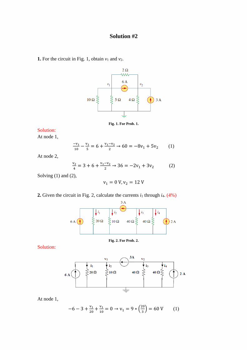
1. For the circuit in Fig. 1, obtain v1 and v2.
Fig. 1. For Prob. 1.
Solution:
At node 1,
−v1
10−
v1
5= 6 +
v1−v2
2→ 60 = −8v1 + 5v2 (1)
At node 2,
v2
4= 3 + 6 +
v1−v2
2→ 36 = −2v1 + 3v2 (2)
Solving (1) and (2),
v1 = 0 V, v2 = 12 V
2. Given the circuit in Fig. 2, calculate the currents i1 through i4. (4%)
Fig. 2. For Prob. 2.
Solution:
At node 1,
−6 − 3 +v1
20+
v1
10= 0 → v1 = 9 ∗ (
20
3) = 60 V (1)

At node 2,
3 − 2 +v2
40+
v2
40= 0 → v2 = −1 ∗ (
1600
80) = −20 V (2)
i1 =v1
20= 3 A, i2 =
v1
10= 6 A,
i3 =v2
40= −500 mA, i4 =
v2
40= −500 mA.
3. Solve for V1 in the circuit of Fig. 3 using nodal analysis.
Fig. 3. For Prob. 3.
Solution:
Set the bottom of the circuit as the reference node.
At node 1:
(V1−10)
5+
(V1−10)
10+
(V1−0)
10+
(V1−20)
4= 0,
(0.2 + 0.1 + 0.1 + 0.25)V1 = 2 + 1 + 5,
V1 = 8/0.65= 160/13=12.308 V.
4. Using nodal analysis, find vo in the circuit of Fig. 4.
Fig. 4. For Prob. 4.
Solution:

i1 + i2 + i3 = 0 → V1
10+
(V1 − 60) − 0
20+
V1 − 5V0
20= 0
But V0 =2
5V1 , so that 2V1 + V1 − 60 + V1 − 2V1 = 0
or v1 = 60/2 =30 V, therefore v0 = 2v1/5 = 12 V.
5. Apply nodal analysis to find i0 and the power dissipated in each resistor in the
circuit of Fig. 5.
Fig. 5. For Prob. 5.
Solution:
Nodes 1 and 2 form a supernode so that v1 = v2 + 10 (1)
At the supernode, 2 + 6v1 + 5v2 = 3(v3 − v2) → 2 + 6v1 + 8v2 = 3v3 (2)
At node 3, 2 + 4 = 3(v3 − v2) → v3 = v2 + 2 (3)
Substituting (1) and (3) into (2),
2 + 6v2 + 60 + 8v2 = 3v2 + 6 → v2 =−56
11= 5.1 V
v1 = v2 + 10 =54
11=4.9 V
i0 = 6v1 = 29.45A
P65 = v12G = (
54
11)26 = 144.6W
P55 = v22G = (
−56
11)25 = 129.6W
P35 = (v2 − v3)2G = (2)23 = 12W
V2 V1 V3
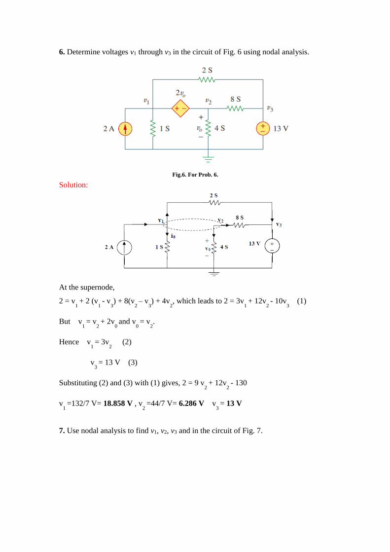
6. Determine voltages v1 through v3 in the circuit of Fig. 6 using nodal analysis.
Fig.6. For Prob. 6.
Solution:
At the supernode,
2 = v1
+ 2 (v1
- v3) + 8(v
2 – v
3) + 4v
2, which leads to 2 = 3v
1 + 12v
2 - 10v
3 (1)
But v1
= v2
+ 2v0 and v
0 = v
2.
Hence v1
= 3v2
(2)
v3
= 13 V (3)
Substituting (2) and (3) with (1) gives, 2 = 9 v2
+ 12v2
- 130
v1
=132/7 V= 18.858 V , v2
=44/7 V= 6.286 V v3
= 13 V
7. Use nodal analysis to find v1, v2, v3 and in the circuit of Fig. 7.
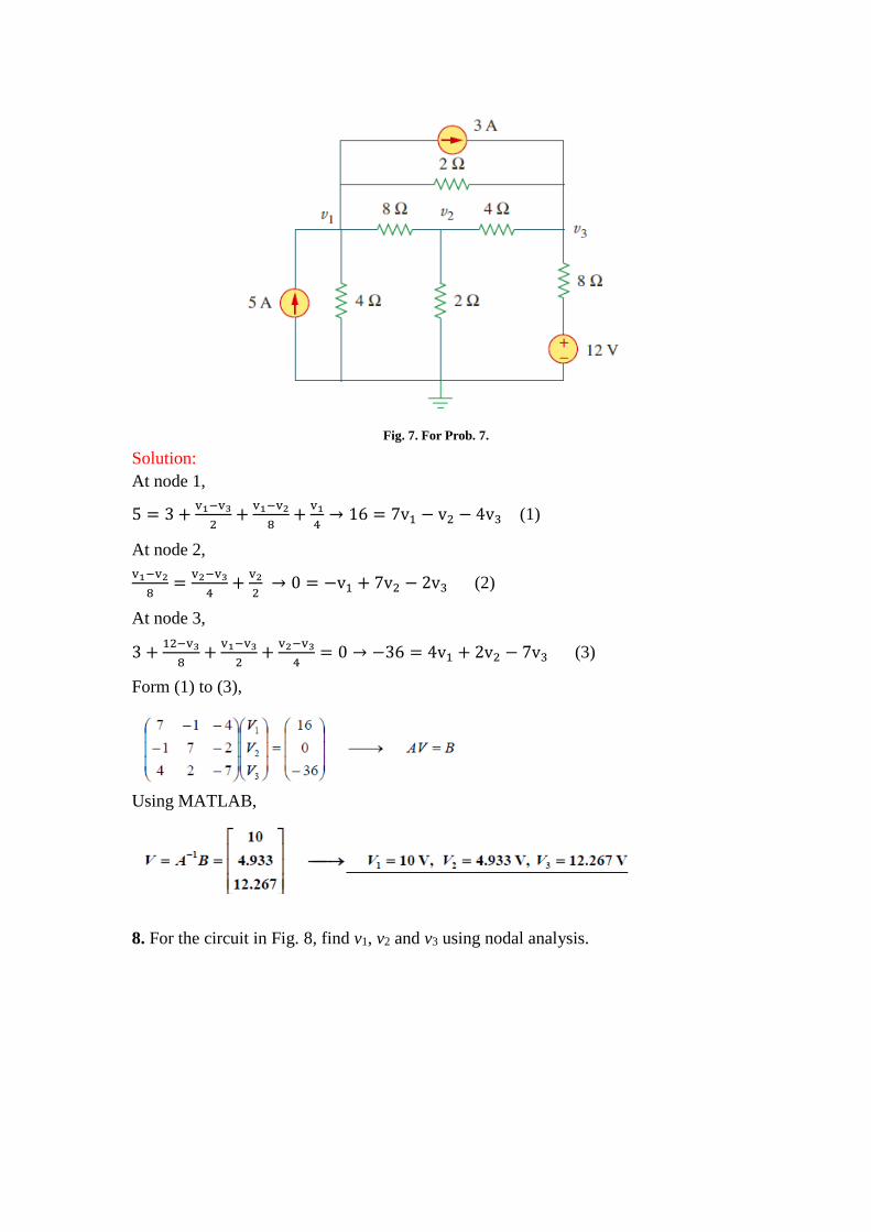
Fig. 7. For Prob. 7.
Solution:
At node 1,
5 = 3 +v1−v3
2+
v1−v2
8+
v1
4→ 16 = 7v1 − v2 − 4v3 (1)
At node 2,
v1−v2
8=
v2−v3
4+
v2
2 → 0 = −v1 + 7v2 − 2v3 (2)
At node 3,
3 +12−v3
8+
v1−v3
2+
v2−v3
4= 0 → −36 = 4v1 + 2v2 − 7v3 (3)
Form (1) to (3),
Using MATLAB,
8. For the circuit in Fig. 8, find v1, v2 and v3 using nodal analysis.
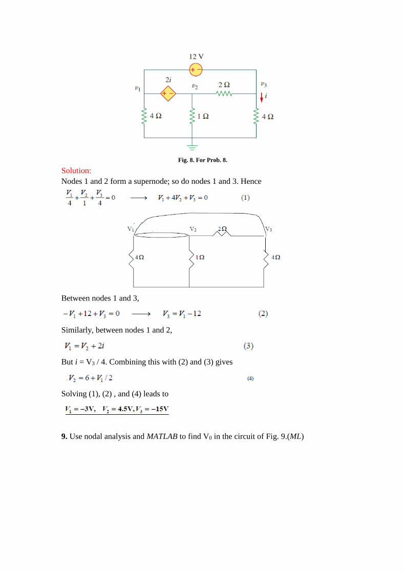
Fig. 8. For Prob. 8.
Solution:
Nodes 1 and 2 form a supernode; so do nodes 1 and 3. Hence
Between nodes 1 and 3,
Similarly, between nodes 1 and 2,
But i = V3 / 4. Combining this with (2) and (3) gives
Solving (1), (2) , and (4) leads to
9. Use nodal analysis and MATLAB to find V0 in the circuit of Fig. 9.(ML)

Fig. 9. For Prob. 9.
Solution:
Consider the circuit below .
Use nodal analysis at nodes 1~4,
Now we can use MATLAB to solve for the unknown node voltage.

10. Calculate the node voltages v1, v2, and v3 in the circuit of Fig. 10.(ML)
Fig.10. For Prob.10.
Solution:
At node 1,
At node 2,

But . Hence, (2) becomes
At node 3,
Putting (1), (3), and (4) in matrix form produces
Using MATLAB leads to
Thus,
11. Determine which of the circuits in Fig. 11 is planar and redraw it with no crossing
branches.

Fig. 11. For Prob. 11.
Solution:
(a) This is a planar circuit because it can be redraw as shown below,
(b) This is a planar circuit because it can be redraw as shown below,
12. Apply mesh analysis to the circuit in Fig. 12 and obtain Io. (ML)

Fig. 12. For Prob.12.
Solution:
Consider the circuit below with the mesh currents.
𝐼1 = −5𝐴 (1)
1(𝐼2 − 𝐼1) + 2(𝐼2 − 𝐼4) + 22.5 + 4𝐼2 = 0
7𝐼2 − 2𝐼4 = −27.5 (2)
−60 + 4𝐼3 + 3𝐼4 + 1𝐼4 + 2(𝐼4 − 𝐼2) + 2(𝐼3 − 𝐼1) = 0 𝑠𝑢𝑝𝑒𝑟 𝑚𝑒𝑠ℎ
−2𝐼2 + 6𝐼3 + 6𝐼4 = 60 − 10 = 50 (3)
But, we need one more equation, so we use the constraint equation –I3+I4 = 10. This
now gives us three equations with three unknows.
We can now use MATLAB to solve the problem.

0 1 2 5 ( 1.375)A 3.625AI I I
13. For the bridge network in Fig. 13, find i0 using mesh analysis. (ML)
Fig. 13. For Prob.13.
Solution:
Assume all currents are in mA and apply mesh analysis for mesh 1.
For mesh 2,
For mesh 3,
Solving (1), (2), and (3) using MATLAB, we obtain,
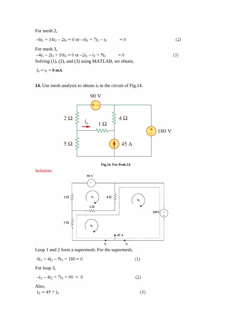
14. Use mesh analysis to obtain i0 in the circuit of Fig.14.
Fig.14. For Prob.14.
Solution:
Loop 1 and 2 form a supermesh. For the supermesh,
For loop 3,
Also,

Solving (1) to (3),
15. Use mesh analysis to find the current i0 in the circuit of Fig. 15. (ML)
Fig.15. For Prob. 15.
Solution:
For loop 1, 16i1 – 10i
2 – 2i
3 = 0 which leads to 8i
1 – 5i
2 – i
3 = 0 (1)
For the supermesh, –35 + 10i2 – 10i
1 + 10i
3 – 2i
1 = 0
Or –6i1 + 5i
2 + 5i
3 = 17.5 (2)
Also, 3i0 = i
3 – i
2 and i
0 = i
1 which leads to 3i
1 = i
3 – i
2 (3)
Solving (1), (2), and (3), we obtain i1 = 1.0098 and
i0
= i1
= 1.0098 A
16. Find the mesh currents in the circuit of Fig. 16. (ML)

Fig. 16. For Prob. 16.
Solution:
Applying mesh analysis leads to;
–12 + 4kI1 – 3kI
2 – 1kI
3 = 0 (1)
–3kI1 + 7kI
2 – 4kI
4 = 0 or –3kI
1 + 7kI
2 = –12 (2)
–1kI1 + 15kI
3 – 8kI
4 – 6kI
5 = 0 or –1kI
1 + 15kI
3 – 6k = –24 (3)
I4 = –3mA (4)
–6kI3 – 8kI
4 + 16kI
5 = 0 or –6kI
3 + 16kI
5 = –24 (5)
Putting these in matrix form (having substituted I4 = 3mA in the above),
ZI = V
Using MATLAB,
>> Z = [4,-3,-1,0;-3,7,0,0;-1,0,15,-6;0,0,-6,16]
Z =
4 -3 -1 0
-3 7 0 0
-1 0 15 -6
0 0 -6 16
>> V = [12,-12,-24,-24]'

V =
12
-12
-24
-24
We obtain,
>> I = inv(Z)*V
I= 1.6196 mA
-1.0202 mA
-2.461 mA
-3 mA
-2.423 mA
17. Find vo and io in the circuit of Fig. 17. (ML)
Fig. 17. For Prob. 17.
Solution:
For mesh 2,
But at node A, i0 = i1 – i2 so that (1) becomes i1 = (16/6)i2 (2)
For the supermesh,
or (3)
At node B, i3 + 0.2v0
= 2 + i1
(4)
But, v0 = 10i2 ,so that (4) becomes i3 = 5 + (2/3)i2 (5)
Solving (1) to (5) , i2 = 0.2941 A,
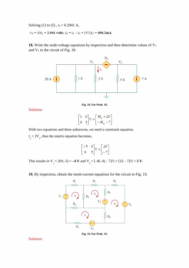
18. Write the node-voltage equations by inspection and then determine values of V1
and V2 in the circuit of Fig. 18.
Fig. 18. For Prob. 18.
Solution:
With two equations and three unknowns, we need a constraint equation,
Ix = 2V
1, thus the matrix equation becomes,
This results in V1 = 20/(–5) = –4 V and V
2 = [–8(–4) – 7]/5 = [32 – 7]/5 = 5 V.
19. By inspection, obtain the mesh-current equations for the circuit in Fig. 19.
Fig. 19. For Prob. 19.
Solution:

R11
= R1
+ R4 + R
6, R
22 = R
2 + R
4 + R
5, R
33 = R
6 + R
7 + R
8
R44
= R3
+ R5 + R
8, R
12 = -R
4, R
13 = -R
6, R
14 = 0, R
23 = 0
R24
= -R5, R
34 = -R
8, again, we note that R
ij = R
ji for all i not equal to j.
The input voltage vector is
= [
𝑉1
−𝑉2
𝑉3
𝑉2 − 𝑉4
]
1 4 6 4 6 1 1
4 2 4 5 5 2 2
6 6 7 8 8 3 3
5 8 3 5 8 4 2 4
0
0
0
0
R R R R R i V
R R R R R i V
R R R R R i V
R R R R R i V V
20. For the transistor circuit of Fig. 20, find vo. Take β= 200, VBE = 0.7 V.
Fig. 20. For Prob. 20.
Solution:
We first determine the Thevenin equivalent for the input circuit.
RTh Th
= 2(3)/(2+6) = 0.75 volts

For loop 1, -0.75 + 1.5kIB
+ VBE
+ 400IE
= 0 = -0.75 + 0.7 + 1500IB
+ 400(1 +β)IB
IB
= 0.05/81,900 = 0.61 uA
v0
= 400IE
= 400(1 + β)IB
= 49 mV