solid-state overload relays rw-e - weg.net · starters data is subject to change without notice....
TRANSCRIPT

218 | 1-800-ASK4WEG | www.weg.net/us
Ap
pend
ixA
Ap
pend
ixB
General
Inform
ation
Circuit
Pro
tection
Disco
nnect S
witches
Mo
tor
Pro
tec
tors
Overlo
ads
Relays
Pushb
uttons
and P
ilot
Lights
Terminal
Blo
cksC
ontacto
rsP
ow
er Facto
r C
orrectio
n
Enclo
sed
Starters
Data is subject to change without notice.
Overloads Solid-State Overload Relays
RW-EThe new RW_E Solid State Overload relays are developed with cutting edge technology according to the most demanding standards worldwide. With its wide current/AMP setting; the RW_E OL Relay can be used for protection of electric motors of different power ratings. The benefit is versatility and flexibility for manufacturers due to the possibility of standardization of control panels. This Solid State Overload Relay can be directly mounted on WEG Contactors (CWM and CWB lines) providing very reliable and flexible motor starter units. The RW_E counts on two independent and highly reliable built in auxiliary contacts that assure the motor is switched off when a failure occurs.
Standard Features • 3-pole solid state overload relays with adjustable trip class: 10, 20 and 30• Self-powered• Wide adjustment range (5:1)• Thermal memory• Phase loss protection (less than 5 seconds)• Phase unbalance protection (>40% between phases)• Temperature compensated (-20 °C up to +60 °C)• Manual or automatic reset modes• Direct mounting on CWB9...38 and CWM9...105 contactors• Separate mounting is possible with accessories 1NO + 1NC built in auxiliary contacts
- -
RWM - Solid State OL for CWM 40: 40A Contactor A4U002: 0.4 - 2.0A RWB - Solid State OL for CWB 112: 112A Contactor A4U008: 1.6 - 8.0A
420: 420A Contactor A4U025: 5 - 25A840: 840A Contactor A4U040: 8 - 40A
A4U056: 14 - 56AA4U112: 28 - 112A
E: Electronic OL A4U250: 50 - 250AA4U420: 85 - 420AA4U840: 170 - 840A
OL Relay Type
Power Poles3: 3-Phase Relay
Overload Current Settings
Chart intended as reference only and not to create part numbers.
A4U040E
Solid-State Overload Relay Catalog Number Sequence
Contactor Series Contactor Frame
RWB 40 3
Ap
pen
dix
AA
pp
end
ixB
Po
wer
Fact
or
Co
rrec
tio
n
Term
inal
B
lock
sP
ush
bu
tto
ns
an
d P
ilot
Lig
hts
Rel
ays
Ove
rlo
ads
Co
ntac
tors
Mo
tor
Pro
tect
ors
Dis
conn
ect
Sw
itch
esC
ircu
itP
rote
ctio
nG
ener
al
Info
rmat
ion
Enc
lose
d
Sta
rter
s
WEG Automation - Products and Solutions | 219Data is subject to change without notice.
OverloadsSolid-State Overload Relays
Ap
pen
dix
AA
pp
end
ixB
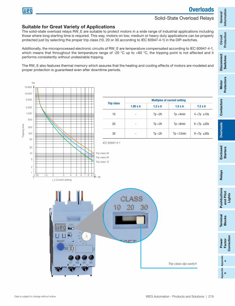
Suitable for Great Variety of ApplicationsThe solid-state overload relays RW_E are suitable to protect motors in a wide range of industrial applications including those where long starting time is required. This way, motors on low, medium or heavy duty applications can be properly protected just by selecting the proper trip class (10, 20 or 30 according to IEC 60947-4-1) in the DIP-switches.
Additionally, the microprocessed electronic circuits of RW_E are temperature compensated according to IEC 60947-4-1, which means that throughout the temperature range of -20 °C up to +60 °C, the tripping point is not affected and it performs consistently without undesirable tripping.
The RW_E also features thermal memory which assures that the heating and cooling effects of motors are modeled and proper protection is guaranteed even after downtime periods.
Trip class dip-switch
IEC 60947-4-1
Trip
pin
g tim
e
Ie x Current setting(A)
t(s)
10,800
10,000
5,000
2,000
1,000
500
200
100
50
20
10
5
2
11.05 1.5 2 3 4 5 6 7 8 9 10
Trip class 30
Trip class 20
Trip class 10
Trip classMultiples of current setting
1.05 x Ir 1.2 x Ir 1.5 x Ir 7.2 x Ir
10 - Tp <2h Tp <4min 4 <Tp ≤10s
20 - Tp <2h Tp <8min 6 <Tp ≤20s
30 - Tp <2h Tp <12min 9 <Tp ≤30s

220 | 1-800-ASK4WEG | www.weg.net/us
Ap
pend
ixA
Ap
pend
ixB
General
Inform
ation
Circuit
Pro
tection
Disco
nnect S
witches
Mo
tor
Pro
tec
tors
Overlo
ads
Relays
Pushb
uttons
and P
ilot
Lights
Terminal
Blo
cksC
ontacto
rsP
ow
er Facto
r C
orrectio
n
Enclo
sed
Starters
Data is subject to change without notice.
Overloads Solid-State Overload Relays
RW_E Solid-State Overload Relays from 0.4 up to 840 A
For direct mountingon contactors
Current range
ADiagram
Max fuse (gL/gG)
ACatalog Number Weight
kg List Price Multiplier
CWB9...38 0.4...2
1L1
2T1
5L3 95
96
97
98
Res
et
Test
4T2 6T3
3L2
16 RWB40E-3-A4U002
0.250 $92
Z2
CWB9...38 1.6...8 32 RWB40E-3-A4U008
CWB9...38 5...25 63 RWB40E-3-A4U025
CWB9...38 8...40 125 RWB40E-3-A4U040
CWM9...40 0.4...2 16 RWM40E-3-A4U002
0.250 $92CWM9...40 1.6...8 32 RWM40E-3-A4U008
CWM9...40 5..25 63 RWM40E-3-A4U025
CWM9...40 8...40 125 RWM40E-3-A4U040
CWM50...105 14...56 160 RWM112E-3-A4U056 0.918 $225
CWM50...105 28...112 250 RWM112E-3-A4U112
For separate mounting or by connector links1)
Current range
ADiagram
Max fuse (gL/gG)
ACatalog Number Weight
kg List Price Multiplier
CWM112...500
50...250
1L1
2T1
5L3 95
96
97
98
Res
et
Test
4T2 6T3
3L2
500 RWM420E-3-A4U2502,520
$490
Z285...420 710 RWM420E-3-A4U420 $580
CWM150...800 170....840 1,250 RWM840E-3-A4U840 4,150 $1,300
Note: 1) RWM840E model allows two different types of connection to contactor: a) By connecting the contactor cables to relay busbars; b) By removing the relay busbars and using the Ø32 mm window for the passage of the contactor cables.
0.250 $145
0.250 $145
0.918 $240
Ap
pen
dix
AA
pp
end
ixB
Po
wer
Fact
or
Co
rrec
tio
n
Term
inal
B
lock
sP
ush
bu
tto
ns
an
d P
ilot
Lig
hts
Rel
ays
Ove
rlo
ads
Co
ntac
tors
Mo
tor
Pro
tect
ors
Dis
conn
ect
Sw
itch
esC
ircu
itP
rote
ctio
nG
ener
al
Info
rmat
ion
Enc
lose
d
Sta
rter
s
WEG Automation - Products and Solutions | 221Data is subject to change without notice.
OverloadsSolid-State Overload Relays
Ap
pen
dix
AA
pp
end
ixB
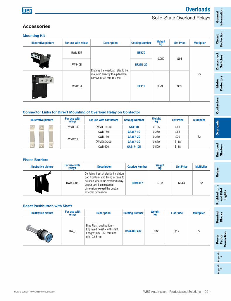
Illustrative picture For use with relays Description Catalog Number Weight
kg List Price Multiplier
RWM420E
Contains 1 set of plastic insulators (top / bottom) and fixing screws to be used where the overload relay power terminals external dimension exceed the busbar external dimension
IBRW317 0.044 $3.65 Z2
Phase Barriers
Illustrative picture For use with relays For use with contactors Catalog Number Weight
kg List Price Multiplier
RWM112E CWM112/150 GA117D 0.135 $41
Z2RWM420E
CWM150 GA317-1D 0.250 $68
CWM180 GA317-2D 0.270 $70
CWM250/300 GA317-3D 0.630 $118
CWM400 GA317-10D 0.500 $118
Connector Links for Direct Mounting of Overload Relay on Contactor
Mounting Kit
Illustrative picture For use with relays Description Catalog Number Weightkg List Price Multiplier
RWM40E
Enables the overload relay to be mounted directly to a panel via screws or 35 mm DIN rail
BF27D
0.050 $14
Z2
RWB40E BF27D-2D
RWM112E BF112 0.230 $31
Illustrative picture For use with relays Description Catalog Number Weight
kg List Price Multiplier
RW_E
Blue Flush pushbutton - Engraved Reset - with shaft. Length: max. 250 mm andmin. 22.5 mm
CSW-BHF437 0.032 $12 Z2
Reset Pushbutton with Shaft
Accessories
222 | 1-800-ASK4WEG | www.weg.net/us
Ap
pend
ixA
Ap
pend
ixB
General
Inform
ation
Circuit
Pro
tection
Disco
nnect S
witches
Mo
tor
Pro
tec
tors
Overlo
ads
Relays
Pushb
uttons
and P
ilot
Lights
Terminal
Blo
cksC
ontacto
rsP
ow
er Facto
r C
orrectio
n
Enclo
sed
Starters
Data is subject to change without notice.
Overloads Solid-State Overload Relays
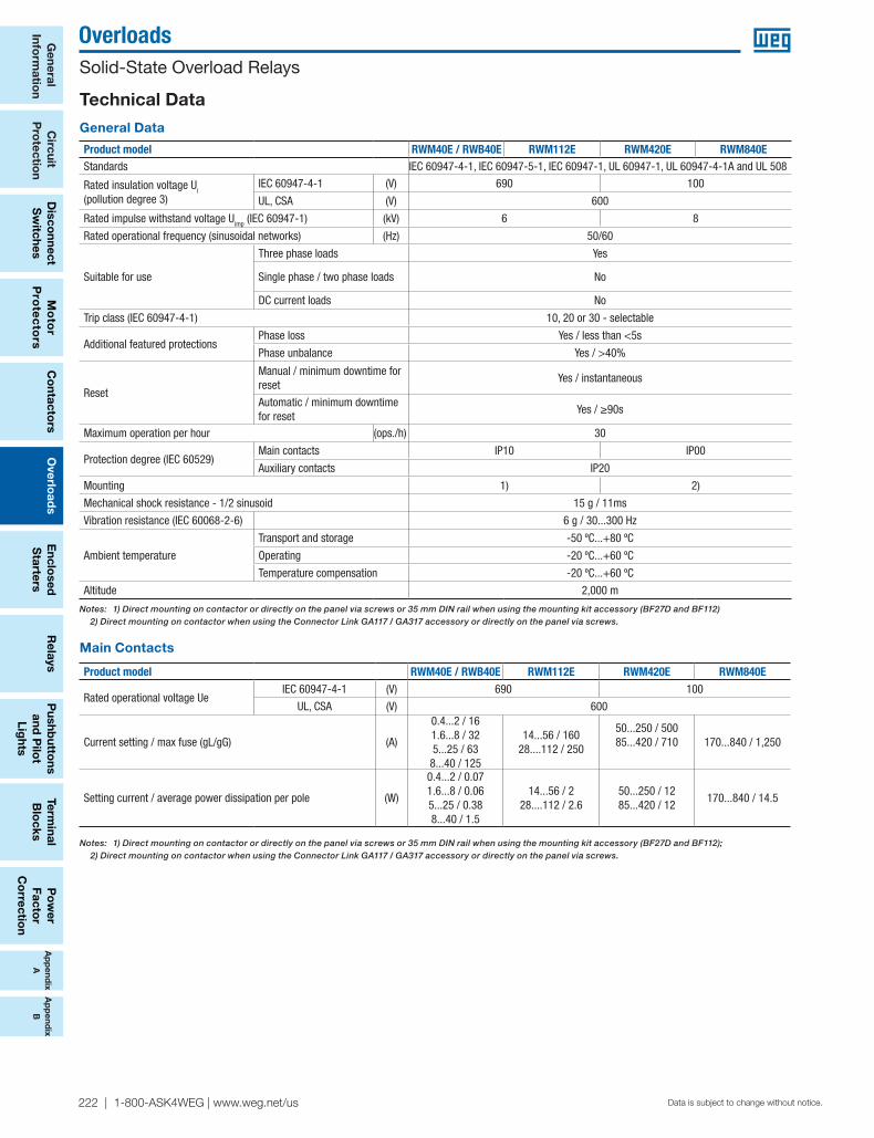
Main Contacts
Technical Data
Product model RWM40E / RWB40E RWM112E RWM420E RWM840E
Rated operational voltage Ue IEC 60947-4-1 (V) 690 100
UL, CSA (V) 600
Current setting / max fuse (gL/gG) (A)
0.4...2 / 161.6...8 / 325...25 / 638...40 / 125
14...56 / 16028....112 / 250
50...250 / 50085...420 / 710 170...840 / 1,250
Setting current / average power dissipation per pole (W)
0.4...2 / 0.071.6...8 / 0.065...25 / 0.388...40 / 1.5
14...56 / 228....112 / 2.6
50...250 / 1285...420 / 12
170...840 / 14.5
Notes: 1) Direct mounting on contactor or directly on the panel via screws or 35 mm DIN rail when using the mounting kit accessory (BF27D and BF112) 2) Direct mounting on contactor when using the Connector Link GA117 / GA317 accessory or directly on the panel via screws.
Notes: 1) Direct mounting on contactor or directly on the panel via screws or 35 mm DIN rail when using the mounting kit accessory (BF27D and BF112); 2) Direct mounting on contactor when using the Connector Link GA117 / GA317 accessory or directly on the panel via screws.
Product model RWM40E / RWB40E RWM112E RWM420E RWM840EStandards IEC 60947-4-1, IEC 60947-5-1, IEC 60947-1, UL 60947-1, UL 60947-4-1A and UL 508
Rated insulation voltage Ui
(pollution degree 3)IEC 60947-4-1 (V) 690 100
UL, CSA (V) 600
Rated impulse withstand voltage Uimp (IEC 60947-1) (kV) 6 8
Rated operational frequency (sinusoidal networks) (Hz) 50/60
Suitable for use
Three phase loads Yes
Single phase / two phase loads No
DC current loads No
Trip class (IEC 60947-4-1) 10, 20 or 30 - selectable
Additional featured protectionsPhase loss Yes / less than <5s
Phase unbalance Yes / >40%
Reset
Manual / minimum downtime for reset
Yes / instantaneous
Automatic / minimum downtime for reset
Yes / ≥90s
Maximum operation per hour (ops./h) 30
Protection degree (IEC 60529) Main contacts IP10 IP00
Auxiliary contacts IP20
Mounting 1) 2)
Mechanical shock resistance - 1/2 sinusoid 15 g / 11ms
Vibration resistance (IEC 60068-2-6) 6 g / 30...300 Hz
Ambient temperature
Transport and storage -50 ºC...+80 ºC
Operating -20 ºC...+60 ºC
Temperature compensation -20 ºC...+60 ºC
Altitude 2,000 m
General Data
Ap
pen
dix
AA
pp
end
ixB
Po
wer
Fact
or
Co
rrec
tio
n
Term
inal
B
lock
sP
ush
bu
tto
ns
an
d P
ilot
Lig
hts
Rel
ays
Ove
rlo
ads
Co
ntac
tors
Mo
tor
Pro
tect
ors
Dis
conn
ect
Sw
itch
esC
ircu
itP
rote
ctio
nG
ener
al
Info
rmat
ion
Enc
lose
d
Sta
rter
s
WEG Automation - Products and Solutions | 223Data is subject to change without notice.
OverloadsSolid-State Overload Relays
Ap
pen
dix
AA
pp
end
ixB
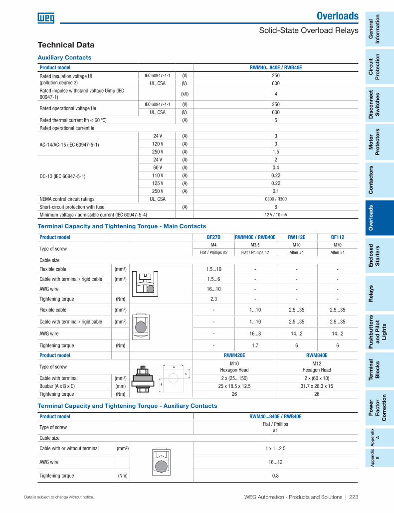
Technical Data
Auxiliary Contacts
Product model RWM40...840E / RWB40E
Rated insulation voltage Ui(pollution degree 3)
IEC 60947-4-1 (V) 250
UL, CSA (V) 600Rated impulse withstand voltage Uimp (IEC 60947-1)
(kV) 4
Rated operational voltage UeIEC 60947-4-1 (V) 250
UL, CSA (V) 600
Rated thermal current Ith ≤ 60 ºC) (A) 5
Rated operational current Ie
AC-14/AC-15 (IEC 60947-5-1)
24 V (A) 3
120 V (A) 3
250 V (A) 1.5
DC-13 (IEC 60947-5-1)
24 V (A) 2
60 V (A) 0.4
110 V (A) 0.22
125 V (A) 0.22
250 V (A) 0.1
NEMA control circuit ratings UL, CSA C300 / R300
Short-circuit protection with fuse (A) 6
Minimum voltage / admissible current (IEC 60947-5-4) 12 V / 10 mA
Terminal Capacity and Tightening Torque - Auxiliary Contacts
Product model RWM40...840E / RWB40E
Type of screwFlat / Phillips
#1Cable size
Cable with or without terminal (mm²) 1 x 1...2.5
AWG wire 16...12
Tightening torque (Nm) 0.8
Product model BF27D RWM40E / RWB40E RW112E BF112
Type of screwM4 M3.5 M10 M10
Flat / Phillips #2 Flat / Phillips #2 Allen #4 Allen #4
Cable size
Flexible cable (mm²) 1.5...10 - - -
Cable with terminal / rigid cable (mm²) 1.5...6 - - -
AWG wire 16...10 - - -
Tightening torque (Nm) 2.3 - - -
Flexible cable (mm²) - 1...10 2.5...35 2.5...35
Cable with terminal / rigid cable (mm²) - 1...10 2.5...35 2.5...35
AWG wire - 16...8 14...2 14...2
Tightening torque (Nm) - 1.7 6 6
Product model RWM420E RWM840E
Type of screw
A
C
B
M10Hexagon Head
M12Hexagon Head
Cable with terminal (mm²) 2 x (25...150) 2 x (60 x 10)
Busbar (A x B x C) (mm) 25 x 18.5 x 12.5 31.7 x 28.3 x 15
Tightening torque (Nm) 26 26
Terminal Capacity and Tightening Torque - Main Contacts
224 | 1-800-ASK4WEG | www.weg.net/us
Ap
pend
ixA
Ap
pend
ixB
General
Inform
ation
Circuit
Pro
tection
Disco
nnect S
witches
Mo
tor
Pro
tec
tors
Overlo
ads
Relays
Pushb
uttons
and P
ilot
Lights
Terminal
Blo
cksC
ontacto
rsP
ow
er Facto
r C
orrectio
n
Enclo
sed
Starters
Data is subject to change without notice.
Overloads Solid-State Overload Relays
Technical Data
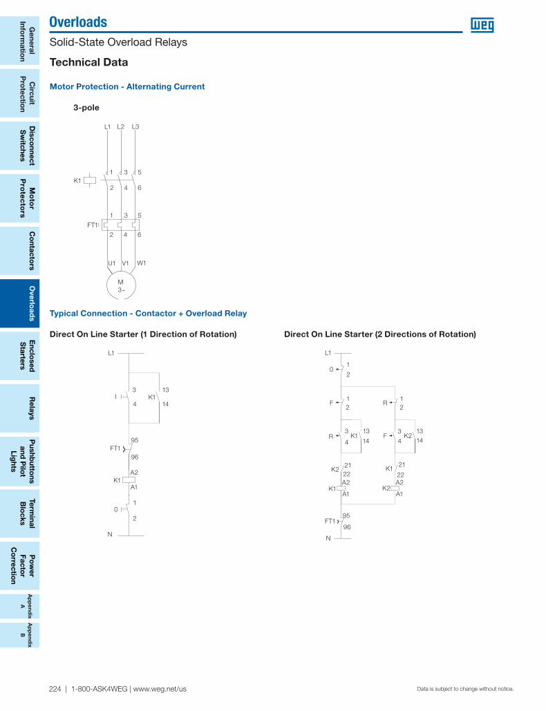
Motor Protection - Alternating Current
3-pole
Typical Connection - Contactor + Overload Relay
Direct On Line Starter (1 Direction of Rotation) Direct On Line Starter (2 Directions of Rotation)
A2
4
3
A1
L1
N
4
3
2
1
A2
A1
2
1
2
1
95
9696
95
14
13
14
13
22
21
22
21
K1
R
F
K2
K1
0
FT1
F
R
K2
K2 K1
L1
01
1
3 3
4 4
13 13
14 14K1
K1
K1
FT195
96
N
K2
K221 21
22A2
A1 A1
A222
K2
1
2
2 22F
F
R
R
K1
K1I
FT1
0
A2
95
4
3 13
14
A1
9696
95
2
1
L1
N
L1
I3
4
95
96
A2
A1K1
01
2
N
K113
14
FT1
2
1
4 6
3 5
42 6
1 3 5
FT1
U1 V1 W1
K1
M1~
L1 L2 L3L1 L2 L3
5
5
6
6
3
3
4
4
1
1
2
2
K1
U1 V1
M3~
W1
FT1

Ap
pen
dix
AA
pp
end
ixB
Po
wer
Fact
or
Co
rrec
tio
n
Term
inal
B
lock
sP
ush
bu
tto
ns
an
d P
ilot
Lig
hts
Rel
ays
Ove
rlo
ads
Co
ntac
tors
Mo
tor
Pro
tect
ors
Dis
conn
ect
Sw
itch
esC
ircu
itP
rote
ctio
nG
ener
al
Info
rmat
ion
Enc
lose
d
Sta
rter
s
WEG Automation - Products and Solutions | 225Data is subject to change without notice.
OverloadsSolid-State Overload Relays
Ap
pen
dix
AA
pp
end
ixB
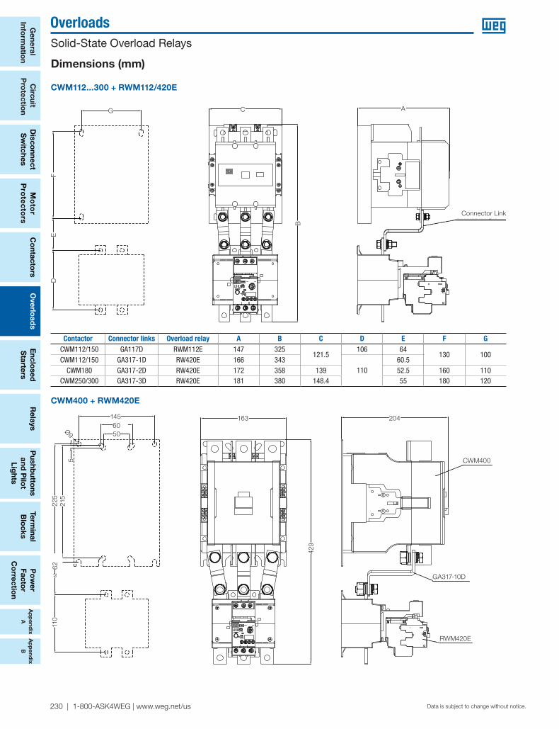
Dimensions (mm)
RWM40E + BF27
45
106,
5
94,1
BF27D
DIN 35 mm
RWM40E
60
4,5
6,8
4,5
35
5
60
4,5
6,8
4,5
35
5
106.
5
45
6.8
4.5
4.5
6035
5
DIN 35 mm
94.1
RWM40E
BF27D
RWM40E RWB40E
45
73,2
97,61
85,64545
73,2
97,61
85,685.673
.2
97.6
1
45
84,4
96
84,145
84,4
96
84,145 84.1
84.4 96
226 | 1-800-ASK4WEG | www.weg.net/us
Ap
pend
ixA
Ap
pend
ixB
General
Inform
ation
Circuit
Pro
tection
Disco
nnect S
witches
Mo
tor
Pro
tec
tors
Overlo
ads
Relays
Pushb
uttons
and P
ilot
Lights
Terminal
Blo
cksC
ontacto
rsP
ow
er Facto
r C
orrectio
n
Enclo
sed
Starters
Data is subject to change without notice.
Overloads Solid-State Overload Relays
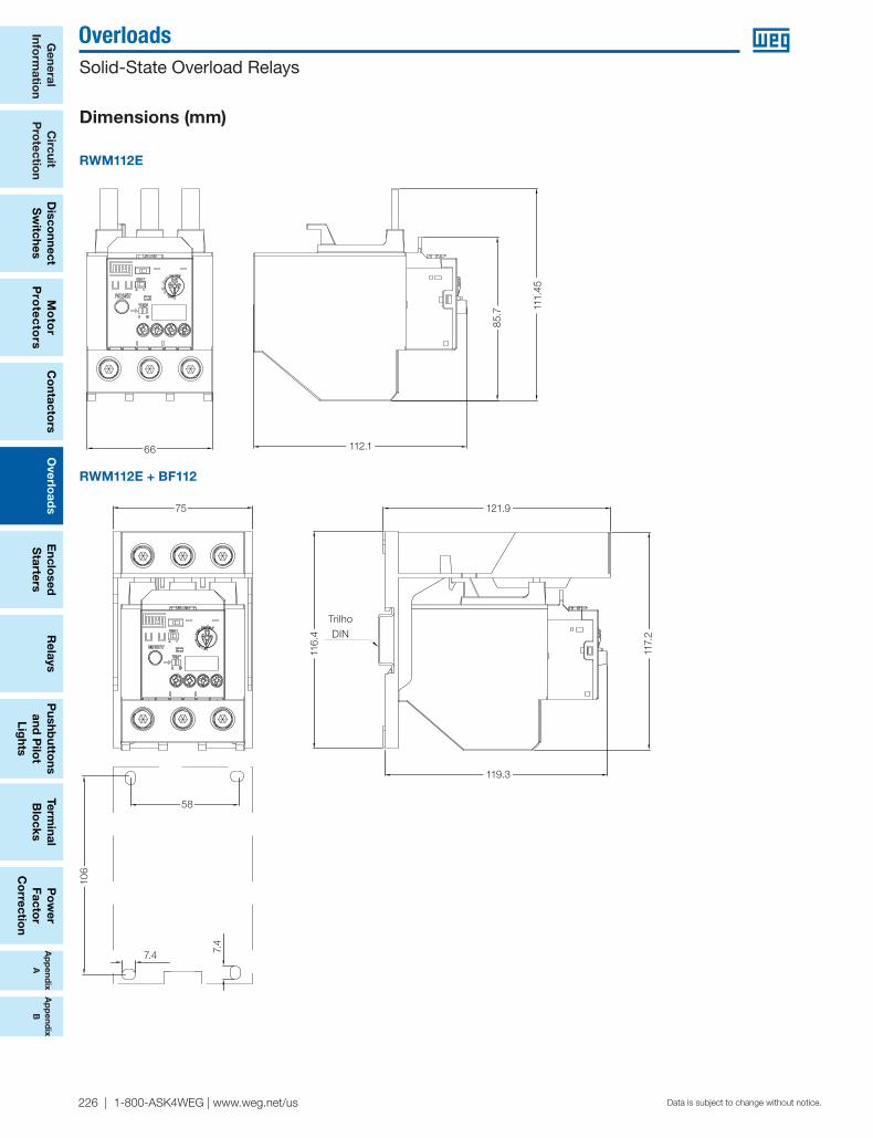
RWM112E
RWM112E + BF112
66
85,7
111,45
112,166
85,7
111,45
112,166 112.1
85.7 11
1.45
75
116,4 TRILHO DIN
58
106
119,3
121,9
7,4
7,4
117,2
75 121.9
119.3
58
7.4 7.4
106
TrilhoDIN
116.
4
117.
2
Dimensions (mm)
Ap
pen
dix
AA
pp
end
ixB
Po
wer
Fact
or
Co
rrec
tio
n
Term
inal
B
lock
sP
ush
bu
tto
ns
an
d P
ilot
Lig
hts
Rel
ays
Ove
rlo
ads
Co
ntac
tors
Mo
tor
Pro
tect
ors
Dis
conn
ect
Sw
itch
esC
ircu
itP
rote
ctio
nG
ener
al
Info
rmat
ion
Enc
lose
d
Sta
rter
s
WEG Automation - Products and Solutions | 227Data is subject to change without notice.
OverloadsSolid-State Overload Relays
Ap
pen
dix
AA
pp
end
ixB
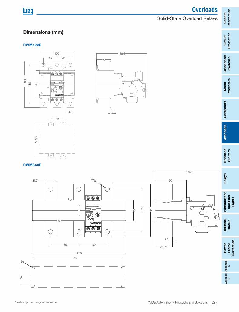
RWM420E
Dimensions (mm)
RWM840E
265
80 80
120
150
Ø13
60
31,7
184,1
50,25
90
250
50
Ø5
31.7
80 80
265
50.25
9.5
90
184.1
250
50
Ø5
60 120
150
Ø13
120
93155
130
45 45
25
169,6
50
5
40
109,9
155
120 169.6
50
5
4545
25
40
109.
9
130
93
228 | 1-800-ASK4WEG | www.weg.net/us
Ap
pend
ixA
Ap
pend
ixB
General
Inform
ation
Circuit
Pro
tection
Disco
nnect S
witches
Mo
tor
Pro
tec
tors
Overlo
ads
Relays
Pushb
uttons
and P
ilot
Lights
Terminal
Blo
cksC
ontacto
rsP
ow
er Facto
r C
orrectio
n
Enclo
sed
Starters
Data is subject to change without notice.
Overloads Solid-State Overload Relays
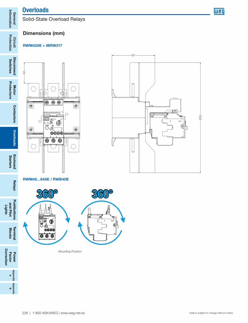
RWM420E + IBRW317
Mounting Position
RWM40...840E / RWB40E
360° 360°
50
97
255
Dimensions (mm)

Ap
pen
dix
AA
pp
end
ixB
Po
wer
Fact
or
Co
rrec
tio
n
Term
inal
B
lock
sP
ush
bu
tto
ns
an
d P
ilot
Lig
hts
Rel
ays
Ove
rlo
ads
Co
ntac
tors
Mo
tor
Pro
tect
ors
Dis
conn
ect
Sw
itch
esC
ircu
itP
rote
ctio
nG
ener
al
Info
rmat
ion
Enc
lose
d
Sta
rter
s
WEG Automation - Products and Solutions | 229Data is subject to change without notice.
OverloadsSolid-State Overload Relays
Ap
pen
dix
AA
pp
end
ixB
CWM9...105 + RWM40...112E and CWB9...38 + RWB40E
Contactor Type ofcontactor coil A B C
CWM9...18CA 94.3
158 45CC 125.1
CWM25CA 94.9
159.3 45CC 124.8
CWM32/40CA 98.6
166.5 55CC 118.6
CWM50...80CA
122.6 202.7 66CC
CWM95/105CA
126 201.1 75.4CC
CWB9...18CA 89.5
163.1
45CC 98.7
CWB25...38CA 93
166.5CC 102.2
Dimensions (mm)
CWM112 + RWM112E + BF112
TRILHO DIN35mm
C
B
A
DIN rail35 mm
B
C A
CWM112 A B
AC conventional coil - 318.5
Electronic coil 326.5 318.5
BF112
DIN 35mm RWM112E
121,8
A
146
100
130
106
64,5
58
B
GA117D
100
121.8146
GA117D
BF112
A
B
RWM112EDIN 35 mm
130
64.5
106
58
230 | 1-800-ASK4WEG | www.weg.net/us
Ap
pend
ixA
Ap
pend
ixB
General
Inform
ation
Circuit
Pro
tection
Disco
nnect S
witches
Mo
tor
Pro
tec
tors
Overlo
ads
Relays
Pushb
uttons
and P
ilot
Lights
Terminal
Blo
cksC
ontacto
rsP
ow
er Facto
r C
orrectio
n
Enclo
sed
Starters
Data is subject to change without notice.
Overloads Solid-State Overload Relays
Dimensions (mm)
CWM112...300 + RWM112/420E
Contactor Connector links Overload relay A B C D E F GCWM112/150 GA117D RWM112E 147 325
121.5106 64
130 100CWM112/150 GA317-1D RW420E 166 343
11060.5
CWM180 GA317-2D RW420E 172 358 139 52.5 160 110CWM250/300 GA317-3D RW420E 181 380 148.4 55 180 120
CWM400 + RWM420E
163
429
204145
60
225
�9 50
215
5
62110
CWM400
GA317-10D
RWM420E
145 163 204
CWM400
GA317-10D
RWM420E
429
6050
521
522
562
110
Ø9
C
B
AG
FE
D
GARRA DE FIXAÇÃO
G C
B
A
Connector Link
FE
D