protective devices: overload relays - siemens electric ... lv 10 · 2004 sirius overload relays...
TRANSCRIPT
Siemens LV 10 · 2004
5/2 Introduction
SIRIUS overload relays
SIRIUS solid-state overload relays5/6 Up to 630 A,
CLASS 10 and CLASS 20, non-adjustable
5/20 Up to 820 A, CLASS 5 to 30, adjustable5/31 Accessories
SIRIUS thermal overload relays5/33 Up to 100 A, CLASS 10,
non-adjustable5/45 Accessories
Protective Devices:Overload Relays
Siemens LV 10 · 20045/2
Controlgear: Overload Relays
Introduction
5
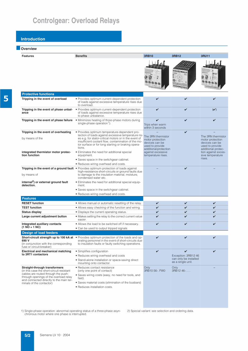
Overview
1) Single-phase operation: abnormal operating status of a three-phase asyn-chronous motor where one phase is interrupted.
2) Special variant: see selection and ordering data.
Features Benefits 3RB10 3RB12 3RU11
Protective functionsTripping in the event of overload • Provides optimum current-dependent protection
of loads against excessive temperature rises due to overload.
Tripping in the event of phase unbal-ance
• Provides optimum current-dependent protection of loads against excessive temperature rises due to phase unbalance.
()
Tripping in the event of phase failure • Minimizes heating of three-phase motors during single-phase operation1).
Trips when warm within 3 seconds
Tripping in the event of overheating
by means of the
integrated thermistor motor protec-tion function
• Provides optimum temperature-dependent pro-tection of loads against excessive temperature ris-es e.g. for stator-critical motors or in the event of insufficient coolant flow, contamination of the mo-tor surface or for long starting or braking opera-tions.
• Eliminates the need for additional special equipment.
• Saves space in the switchgear cabinet.
• Reduces wiring overhead and costs.
–
The 3RN thermistor motor protection devices can be used to provide additional protection against excessive temperature rises.
–
The 3RN thermistor motor protection devices can be used to provide additional protec-tion against exces-sive temperature rises.
Tripping in the event of a ground fault
by means of
internal2) or external ground fault detection.
• Provides optimum protection of loads against high-resistance short-circuits or ground faults due to damage to the insulation material, moisture, condensed water etc.
• Eliminates the need for additional special equip-ment.
• Saves space in the switchgear cabinet.
• Reduces wiring overhead and costs.
– –
FeaturesRESET function • Allows manual or automatic resetting of the relay.
TEST function • Allows easy checking of the function and wiring.
Status display • Displays the current operating status.
Large current adjustment button • Makes setting the relay to the correct current value easier.
Integrated auxiliary contacts (1 NO + 1 NC)
• Allows the load to be switched off if necessary.
• Can be used to output tripped signals
Design of load feedersShort-circuit strength up to 100 kA at 690 V(in conjunction with the corresponding fuse or circuit-breaker)
• Provides optimum protection of the loads and op-erating personnel in the event of short-circuits due to insulation faults or faulty switching operations.
Electrical and mechanical matching to 3RT1 contactors
• Simplifies configuration
• Reduces wiring overhead and costs
• Stand-alone installation or space-saving direct mounting onto contactor.
Exception: 3RB12 46 can only be installed as a single unit.
Straight-through transformers(in this case the short-circuit resistant cables are routed through the push-through openings of the overload relay and connected directly to the main ter-minals of the contactor)
• Reduces contact resistance (only one point of contact)
• Saves wiring costs (easy, no need for tools, and fast).
• Saves material costs (elimination of the busbars)
• Reduces installation costs.
Only3RB10 56-. FW0
Only3RB12 46-. . . .
–
Siemens LV 10 · 2004 5/3
Controlgear: Overload Relays
Introduction
5
1) Special variant: See selection and ordering data.
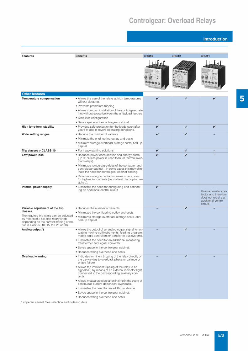
Features Benefits 3RB10 3RB12 3RU11
Other featuresTemperature compensation • Allows the use of the relays at high temperatures
without derating.
• Prevents premature tripping
• Allows compact installation of the controlgear cab-inet without space between the units/load feeders
• Simplifies configuration
• Saves space in the controlgear cabinet.
High long-term stability • Provides safe protection for the loads even after years of use in severe operating conditions.
Wide setting ranges • Reduce the number of variants
• Minimize the engineering outlay and costs
• Minimize storage overhead, storage costs, tied-up capital.
–
Trip classes > CLASS 10 • For heavy starting solutions –
Low power loss • Reduces power consumption and energy costs (up 95 % less power is used than for thermal over-load relays).
• Minimizes temperature rises of the contactor and controlgear cabinet – in some cases this may elim-inate the need for controlgear cabinet cooling.
• Direct mounting to contactor saves space, even for high motor currents (i.e. no heat decoupling re-quired).
–
Internal power supply • Eliminates the need for configuring and connect-ing an additional control circuit.
– –
Uses a bimetal con-tactor and therefore does not require an additional control circuit.
Variable adjustment of the trip classes
The required trip class can be adjusted by means of a six-step rotary knob depending on the current starting condi-tion (CLASS 5, 10, 15, 20, 25 or 30).
• Reduces the number of variants
• Minimizes the configuring outlay and costs
• Minimizes storage overhead, storage costs, and tied-up capital.
– –
Analog output1) • Allows the output of an analog output signal for ac-tuating moving-coil instruments, feeding program-mable logic controllers or transfer to bus systems.
• Eliminates the need for an additional measuring transformer and signal converter.
• Saves space in the controlgear cabinet.
• Reduces wiring overhead and costs.
– –
Overload warning • Indicates imminent tripping of the relay directly on the device due to overload, phase unbalance or phase failure.
• Allows the imminent tripping of the relay to be signaled1) by means of an external indicator light connected to the corresponding auxiliary con-tacts.
• Allows measures to be taken in time in the event of continuous current-dependent overloads.
• Eliminates the need for an additional device.
• Saves space in the controlgear cabinet.
• Reduces wiring overhead and costs.
– –
Siemens LV 10 · 20045/4
Controlgear: Overload Relays
Introduction
5
1) Trip class, CLASS 20 from 3 A to 25 A.
Assembly possible
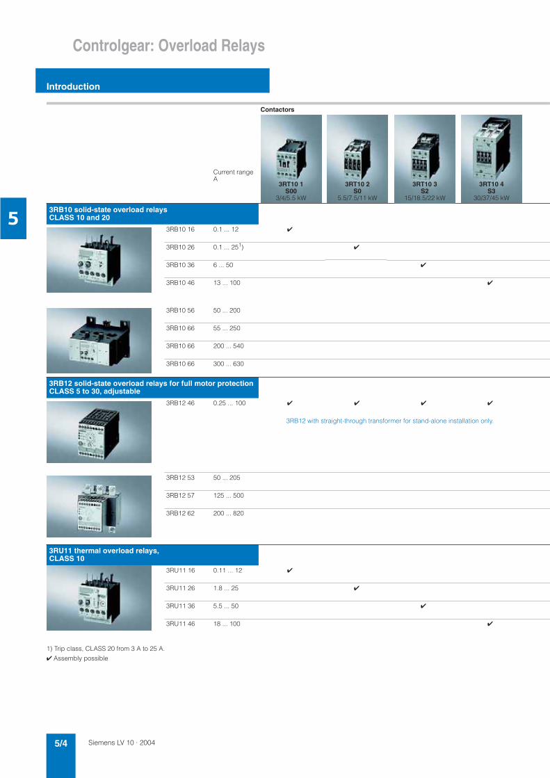
Contactors
Current range A
3RB10 solid-state overload relays CLASS 10 and 20
3RB10 16 0.1 ... 12
3RB10 26 0.1 ... 251)
3RB10 36 6 ... 50
3RB10 46 13 ... 100
3RB10 56 50 ... 200
3RB10 66 55 ... 250
3RB10 66 200 ... 540
3RB10 66 300 ... 630
3RB12 solid-state overload relays for full motor protection CLASS 5 to 30, adjustable
3RB12 46 0.25 ... 100
3RB12 with straight-through transformer for stand-alone installation only.
3RB12 53 50 ... 205
3RB12 57 125 ... 500
3RB12 62 200 ... 820
3RU11 thermal overload relays, CLASS 10
3RU11 16 0.11 ... 12
3RU11 26 1.8 ... 25
3RU11 36 5.5 ... 50
3RU11 46 18 ... 100
3RT10 1S00
3/4/5.5 kW
3RT10 2S0
5.5/7.5/11 kW
3RT10 3S2
15/18.5/22 kW
3RT10 4S3
30/37/45 kW
Siemens LV 10 · 2004 5/5
Controlgear: Overload Relays
Introduction
5
3RT10 5S6
55/75/90 kW
3RT10 6S10
110/132/160 kW
3RT10 7S12
200/250 kW
3TF68/69size. 14
335/450 kW
Siemens LV 10 · 20045/6
SIRIUS Overload Relays
Up to 630 A, CLASS 10 and CLASS 20,non-adjustable
SIRIUS Solid-State Overload Relays
5
Overview
3RB10 solid-state overload relays with screw connection for direct mounting1) and for stand-alone installation2),CLASS 10 and CLASS 20
The 3RB10 solid-state overload relays up to 630 A with internal power supply have been designed for current-dependent pro-tection of loads with normal and heavy starting (see Functions) against excessive temperature rises due to overload, phase un-balance or phase failure. An overload, phase unbalance or phase failure result in an increase of the motor current beyond the set motor rated current. This current rise is detected by the current transformers integrated into the devices and evaluated by corresponding solid-state circuits which then output a pulse to the auxiliary contacts. The auxiliary contacts then switch off the load by means of a contactor. The break time depends on the ratio between the tripping current and operating current Ie and is stored in the form of a long-term stable tripping characteristic (see Characteristics). The "tripped" status is signaled by means of a switch position indicator (see Functions). The contactor is ei-ther reset manually or automatically (see Functions) after the re-covery time has elapsed (see Functions).
The devices are manufactured in accordance with environmen-tal guidelines and contain environmentally friendly and recycla-ble materials.
They comply with important worldwide standards and approv-als.
Specifications
The 3RB10 solid-state overload relays comply with the following standards:• IEC 60947-1/EN 60947-1• IEC 60947-4-1/EN 60947-4-1• IEC 60947-5-1/EN 60947-5-1• UL 508/CSA C 22.2.
The 3RB10 solid-state overload relays are also finger-safe acc. to EN 50274 and climate-proof acc. to IEC 60721.
1) With the suitable terminal brackets (see Accessories), the size S00 to S3 3RB10 solid-state overload relays for direct mounting can also be installed as stand-alone units. The 3RB10 solid-state overload relays with sizes S6 and S10/S12 can be installed as stand-alone units without additional termi-nal brackets. For 3TF68 and 3TF69 contactors, direct mounting is not pos-sible.
2) Size S00 to S6 for screw and snap-on mounting onto 35 mm standard mounting rails, size S3 also for 75 mm standard mounting rails. For size S10 and S12, mounting onto standard mounting rails is not possible.
3) Please ask for approvals for dusty environments.
Benefits
The most important features and benefits of the 3RB10 solid-state overload relays are listed in the overview table in the intro-duction.
Area of application
Fields of application
The 3RB10 solid-state overload relays have been designed for the protection of three-phase motors in sinusoidal 50/60 Hz volt-age networks.
The relay is not suitable for the protection of single-phase AC or DC loads.
For these loads, the 3RU11 thermal overload relay or the 3RB12 solid-state overload relay (only suited for the protection of single-phase AC loads) must be used.
The 3RB10 solid-state overload relays are not suitable for the protection of loads with a grounded neutral point.
Ambient conditions
The devices are insensitive to external influences such as shocks, corrosive environments, ageing, and extreme tempera-ture changes.
In the temperature range from –25 °C to +70 °C, the 3RB10 (S00 – S3) solid-state overload relays compensate the temperature according to IEC 60947-4-1.
For the 3RB10 solid-state overload relays with the sizes S6 and S10/S12, the upper setpoint of the setting range must be re-duced for ambient temperatures ≥ +60 °C by the factor listed in the table below.
"Increased safety" EEx type of protection
The 3RB10 solid-state overload relays comply with the regula-tions for the overload protection of explosion-proof motors with "increased safety" type of protection EEx e EN 50019.
The basic safety and health requirements of ATEX guideline 94/9/EG are fulfilled by compliance with • EN 60947-1• EN 60947-4-1• EN 60947-5-1• EN 60079-14
EU type test certificates for category (2)G3) with the numbers• PTB 01 ATEX 3306 • PTB 01 ATEX 3203 • PTB 01 ATEX 3316 have been issued.
(
&
'
(
&
'
(
-& 0")% ()*)2/ )))%))/"C"+3".)- &+& ()*5&+& &+ '%E" &,0&%."&./+&&%&".&*&00*&%&?)&&/&)+&.)+@+10 )4&0.")2 0'"#)+)1 ()*&/&&.)+@+10 )4&0.")2 0F")/.&%& )2)+&+
Type Derating factor for the upper setpoint for stand-alone installation and an ambient temperature of:
+50 °C +60 °C +70 °C
3RB10 56-.F.0 1.00 1.00 0.80
3RB10 66-.GG0 1.00 1.00 0.80
3RB10 66-.KG0 1.00 1.00 0.93
3RB10 66-.LG0 1.00 0.90 0.80
Type Derating factor for the upper setpoint for mounting onto contactors and an ambient temperature of:
+50 °C +60 °C +70 °C
3RB10 56-.F.0 1.00 0.70 0.60
3RB10 66-.GG0 1.00 0.70 0.60
3RB10 66-.KG0 1.00 0.82 0.70
3RB10 66-.LG0 1.00 0.70 0.60
Siemens LV 10 · 2004 5/7
SIRIUS Overload RelaysSIRIUS Solid-State Overload Relays
Up to 630 A, CLASS 10 and CLASS 20,non-adjustable
5
Design
Mounting options
The 3RB10 solid-state overload relays are suitable for direct and space-saving mounting onto 3RT1 contactors and 3RW30/3RW31 soft starters. The devices can also be installed as single units. Size S00 to S3 3RB10 solid-state overload relays can only be installed as single units in combination with an additional ter-minal bracket.
For more information on the mounting options, please consult the technical specifications as well as the selection and ordering data.
Connections
All sizes of the 3RB10 solid-state overload relays with screw con-nection can be connected to the auxiliary and main circuits. For sizes S3 to S10/S12, the main circuits can also be connected with the help of rails. The 3RB10 contactors are also available in size S6 with a straight-through transformer. In this case, the short-circuit resistant cables for the main circuit are routed di-rectly through the push-through openings of the relay to the con-tactor terminals.
For more information on the different connection options, please consult the technical specifications as well as the selection and ordering data.
Overload relays in star-delta assemblies
When overload relays are used in combination with star-delta as-semblies it must be noted that only 0.58 times the motor current flows through the line contactor. An overload relay mounted onto the line contactor must be set to 0.58 times the motor current.
An assignment of the 3RB10 solid-state overload relays to the line contactors of our 3RA star-delta assemblies can be found under "Controlgear: Contactors and Contactor Assemblies".
Operation with frequency converters
The 3RB10 solid-state overload relays are suitable for frequen-cies of 50/60 Hz and the associated harmonics. This permits the 3RB10 overload relays to be used on the incom-ing side of the frequency converter. If a motor contactor is required on the outgoing side of the fre-quency converter, Siemens recommends the 3RN thermistor motor protection devices or the 3RU11 thermal overload relays for this purpose.
Functions
Control circuit
The 3RB10 solid-state overload relays have an internal power supply, i.e. they do not require an additional supply voltage.
Short-circuit protection
Fuses or circuit-breakers must be used for short-circuit protec-tion. Assignments for the corresponding short-circuit protection devices to the 3RB10 solid-state overload relays with/without contactor can be found in the technical specifications or selec-tion and ordering data.
Trip classes
The 3RB10 solid-state overload relays are available for normal starting conditions with trip CLASS 10 and for heavy starting conditions with trip CLASS 20. Detailed information about trip classes can be found under "Characteristics".
Phase failure protection
The 3RB10 solid-state overload relays are fitted with phase fail-ure protection (see Characteristics) in order to minimize temper-ature rises of the load during single-phase operation.
Phase failure protection is not effective for loads with star-con-nection and a grounded neutral point or a neutral point which is connected to a neutral conductor.
Setting
The 3RB10 solid-state overload relay is set to the motor rated current by means of a rotary knob. The scale of the rotary knob is calibrated in ampere.
Manual and automatic reset
Automatic and manual reset is selected by pressing and turning the blue button (RESET button). If the button is set to manual re-set, the overload relay can be reset directly by pressing the RESET button. Remote resetting is possible in combination with mechanical and electrical RESET modules from the accessories range (see Accessories). If the blue button is set to automatic RESET, the relay is reset automatically.
The relay can only be reset after the recovery time has elapsed.
Recovery time
The recovery time is permanently stored in the 3RB10 solid-state overload relay. If the button is set to automatic RESET, the recov-ery time is about 4 min. after tripping due to overload for sizes S00 - S3 and about 7 min. for sizes S6 - S12. The recovery time allows the load to cool down.
If the button is set to manual RESET, the device can be reset im-mediately.
TEST function
The TEST slide can be used to check whether the operating 3RB10 solid-state overload relay is working properly. Actuating the slide simulates tripping of the relay. During this simulation the NC contact (95-96) is opened and the NO contact (97-98) is closed. This tests whether the auxiliary circuit has been correctly connected to the 3RB10 solid-state overload relay. If the 3RB10 solid-state overload relay has been set to automatic RESET, the overload relay is automatically reset when the TEST slide is re-leased. The relay must be reset with the RESET button if it has been set to manual RESET.
STOP function
If the STOP button is pressed, the NC contact is opened. This switches off the contactor downstream and thus the load. The load is switched on again when the STOP button is released.
Display of the operating status
The status of the 3RB10 solid-state overload relay is displayed by means of the position of the marking on the TEST func-tion/switch position indicator slide. After tripping due to over-load, phase unbalance or phase failure, the marking on the slide is to left on the "O" mark, otherwise it is on the "I" mark.
Auxiliary contacts
The 3RB10 solid-state overload relay is fitted with an NO contact for the "tripped" signal, and an NC contact for switching off the contactor.
Siemens LV 10 · 20045/8
SIRIUS Overload Relays
Up to 630 A, CLASS 10 and CLASS 20,non-adjustable
SIRIUS Solid-State Overload Relays
5
Technical specifications
1) Remote RESET in combination with the corresponding accessories.
2) Terminal compartment: IP00 degree of protection.
3) For the setting ranges 0.1 A ... 0.4 A, 0.4 A ... 1.6 A and 1.5 A ... 6 A: 3 V/m.
4) For screw and snap-on mounting onto 35 mm standard mounting rail; size S3 also for 75 mm standard mounting rail. For more detailed information about terminal brackets please see technical specifications/terminal brackets for stand-alone installation.
Type 3RB10 16 3RB10 26 3RB10 36 3RB10 46 Size S00 S0 S2 S3Overall width 45 mm 45 mm 55 mm 70 mmGeneral specificationsTrips in the event of Overload, phase failure, and phase unbalance (> 40% acc. to NEMA)
Trip class acc. to IEC 60947-4-1 CLASS 10 and 20, depending on the version
Phase failure sensitivity Yes, trips when warm < 3 seconds
Overload warning No
Reset and recovery• Reset option after tripping Manual, remote, and automatic RESET1)• Recovery time For automatic RESET min. approx. 4
For manual RESET min. ImmediatelyFor remote RESET min. Immediately
Features• Display of operating status on device Yes, by means of TEST function/switch position indicator slide• TEST function Yes• RESET button Yes• STOP button Yes
For safe operation of motors with "increased safety" type of protec-tion
EU type test certificate number in accordance with guideline 94/9/EU
PTB 01 ATEX 3306
Ambient temperatures• Storage/transport °C -55 ... + 80• Operation °C -25 ... + 70• Temperature compensation °C up to 70• Permissible rated current at Temperature inside cabinet 60 °C % 100 (over +60 °C current reduction is not required)
Temperature inside cabinet 70 °C % 100 (over +60 °C current reduction is not required)
Repeat terminals• Coil repeat terminals Yes Not required• Auxiliary switch repeat terminal Yes Not required
Degree of protection acc. to IEC 60529 IP20 IP202)
Touch protection acc. to EN 50274 Finger-safe
Shock resistance with sine acc. to IEC 60068-2-27 g/ms 8/10 and 15/11
EMC interference immunity• Conductor-related interference
- Burst acc. to IEC 61000-4-4 (corresponds to degree of severity 3)
kV 2
- Surge acc. to IEC 61000-4-5 (corresponds to degree of severity 3)
kV 2/1 (line to ground/line to line)
• Electrostatic discharge acc. to IEC 61000-4-2 (corresponds to degree of severity 3)
kV 6/8 (contact/air discharge)
• Field-related interference acc. to IEC 61000-4-3 (corresponds to degree of severity 3)
V/m 3 103) 10
EMC interference emission Limit value class B acc. to CISPR 11
Resistance to extreme climates (air humidity) % 100
Dimensions see dimension drawings
Site altitude m up to 2000 m above sea level
Mounting position any
Installation type/mounting Direct mounting/stand-alone installation with terminal bracket4)Main circuitRated insulation voltage Ui (pollution degree 3) V 690 1000
Rated impulse withstand voltage Uimp kV 6 8
Rated operating voltage Ue V 690 1000
Type of current• DC No• AC Yes, 50/60 Hz ± 3 (other frequencies on request)
Current setting A 0.1 - 0.4 ... 3 - 12 0.1 - 0.4 ... 6 - 25 6 - 25 ... 13 - 50 13 - 50 ... 25 - 100
Power loss per unit (max.) W approx. 0.05
Short-circuit protection with fuse without contactor see selection and ordering datawith fuse and contactor see technical specifications (short-circuit protection with fuses for motor
feeders)
Safe isolation between main and auxiliary conducting path
acc. to IEC 60947-1 V on request
Siemens LV 10 · 2004 5/9
SIRIUS Overload RelaysSIRIUS Solid-State Overload Relays
Up to 630 A, CLASS 10 and CLASS 20,non-adjustable
5
1) Remote RESET in combination with the corresponding accessories.
2) Terminal compartment: IP00 degree of protection.
3) For screw and snap-on mounting onto 35 mm standard mounting rails (S10/S12 cannot be mounted onto standard rails).
Type 3RB10 56 3RB10 66 Size S6 S10/S12Overall width 120 mm 145 mmGeneral specificationsTrips in the event of Overload, phase failure, and phase unbalance (> 40% acc. to NEMA)
Trip class acc. to IEC 60947-4-1 CLASS 10 and 20, depending on the version
Phase failure sensitivity Yes, trips when warm < 3 seconds
Overload warning No
Reset and recovery• Reset option after tripping Manual, remote, and automatic RESET1)• Recovery time For automatic RESET min approx. 7 s
For manual RESET min ImmediatelyFor remote RESET min. Immediately
Features• Display of operating status on device Yes, by means of TEST function/switch position indicator slide• TEST function Yes• RESET button Yes• STOP button Yes
For safe operation of motors with "increased safety" type of protec-tion
EU type test certificate number in accordance with guideline 94/9/EU
PTB 01 ATEX 3203 PTB 01 ATEX 3316
Ambient temperatures• Storage/transport °C -55 ... + 80• Operation °C -25 ... + 70• Temperature compensation °C see area of application• Permissible rated current at Temperature inside cabinet 60 °C % see area of application
Temperature inside cabinet 70 °C % see area of application
Repeat terminals• Coil repeat terminals Not required• Auxiliary contact repeat terminal Not required
Degree of protection acc. to IEC 60529 IP202)
Touch protection acc. to EN 50274 Finger-safe with cover
Shock resistance with sine acc. to IEC 60068-2-27 g/ms 8/10 and 15/11
EMC interference immunity• Conductor-related interference
- Burst acc. to IEC 61000-4-4 (corresponds to degree of severity 3)
kV 2
- Surge acc. to IEC 61000-4-5 (corresponds to degree of severity 3)
kV 2/1 (line to ground/line to line)
• Electrostatic discharge acc. to IEC 61000-4-2 (corresponds to degree of severity 3)
kV 6/8 (contact/air discharge)
• Field-related interference acc. to IEC 61000-4-3 (corresponds to degree of severity 3)
V/m 10
EMC interference emission Limit value class B acc. to CISPR 11
Resistance to extreme climates (air humidity) % 100
Dimensions see dimension drawings
Site altitude m up to 2000 m above sea level
Mounting position any
Installation type/mounting Direct mounting/stand-alone installation without additional terminal bracket3)
Main circuitRated insulation voltage Ui (pollution degree 3) V 1000
Rated impulse withstand voltage Uimp kV 8
Rated operating voltage Ue V 1000
Type of current• DC No• AC Yes, 50/60 Hz ± 3 (other frequencies on request)
Current setting A 50 ... 200 55 - 250 ... 300 - 630
Power loss per unit (max.) W approx. 0.05
Short-circuit protection with fuse without contactor see selection and ordering datawith fuse and contactor see technical specifications (short-circuit protection with fuses for motor
feeders)
Safe isolation between main and auxiliary conducting path
acc. to IEC 60947-1 V 1000
Siemens LV 10 · 20045/10
SIRIUS Overload Relays
Up to 630 A, CLASS 10 and CLASS 20,non-adjustable
SIRIUS Solid-State Overload Relays
5
1) The box terminal is removable. Rail and cable lug connections are possi-ble if the box terminal is removed.
Type 3RB10 16 3RB10 26 3RB10 36 3RB10 46 Size S00 S0 S2 S3Overall width 45 mm 45 mm 55 mm 70 mmConnection for main circuitType of connection Screw connection Screw connec-
tion with box terminal
Screw connec-tion with box terminal/bus connection1)
Screw connection• Terminal screw Pozidrive size 2 4 mm Allen
screw• Tightening torque Nm 0.8 ... 1.2 2 ... 2.5 3 ... 4.5 4 ... 6• Conductor cross-sections
(min./max.), 1 or 2 conductorsSolid mm2 2 x (0.5 ... 1.5)
2 x (0.75 ... 2.5)max. 2 x (1 ... 4)
2 x (1 ... 2.5)2 x (2.5 ... 6)max. 2 x (2.5 ... 10)
2 x (0.75 ... 16) 2 x (2.5 ... 16)
Finely stranded without end sleeve mm2 –
Finely stranded with end sleeve mm2 2 x (0.5 ... 1.5)2 x (0.75 ... 2.5)
2 x (1 ... 2.5)2 x (2.5 ... 6)
2 x (0.75 ... 16)1x ( 0.75 ... 25)
2 x (2.5 ... 35)1 x (2.5 ... 50)
Stranded mm2 2 x (0.5 ... 1.5)2 x (0.75 ... 2.5)max. 2 x (1 ... 4)
2 x (1 ... 2.5)2 x (2.5 ... 6)max. 2 x (2.5 ... 10)
2 x (0.75 ... 25)1 x (0.75 ... 35)
2 x (10 ... 50)1 x (10 ... 70)
AWG conductors, solid or stranded AWG 2 x (18 ... 14) 2 x (14 ... 10) 2 x (18 ... 3)1 x (18 ... 1)
2 x (10 ... 1/0)2 x (10 ... 2/0)
Ribbon cables(number x width x circumference)
mm – – 2 x (6 x 9 x 0.8) 2 x (6 x 9 x 0.8)
Bus connection• Terminal screw – M 6 x 20• Tightening torque Nm – 4 ... 6• Conductor cross-section
(min./max.)Finely stranded with cable lug mm2 – 2 x 70Stranded with cable lug mm2 – 3 x 70AWG connections, solid or stranded, with cable lug
AWG – 2/0
With connecting bars (max. width) mm – 12
Straight-through transformer connection• Diameter of opening mm –• Conductor cross-section (max.) NYY mm2 –
H07RN-F mm2 –
Siemens LV 10 · 2004 5/11
SIRIUS Overload RelaysSIRIUS Solid-State Overload Relays
Up to 630 A, CLASS 10 and CLASS 20,non-adjustable
5
1) Screw connection with corresponding box terminal possible (see Accesso-ries)
2) When connecting cable lugs to DIN 46235 use 3RT19 56-4EA1 terminal cover for conductor cross-sections from 95 mm² to ensure phase spacing.
3) When connecting cable lugs to DIN 46234 for conductor cross-sections from 240 mm² as well as DIN 46235 for conductor cross-sections from 185 mm², use 3RT19 66-4EA1 terminal cover to ensure phase spacing.
Type 3RB10 56 3RB10 66 Size S6 S10/S12Overall width 120 mm 145 mmConnection for main circuitType of connection Screw connection with box termi-
nal/bus connection/straight-through transformer connection1)
Screw connection with box terminal/bus connection1)
Screw connection• Terminal screw 4 mm Allen screw 5 mm Allen screw• Tightening torque Nm 10 ... 12 20 ... 22• Conductor cross-sections
(min./max.), 1 or 2 conductorsSolid mm2 –Finely stranded without end sleeve mm2 with 3RT19 55-4G box terminal:
2 x (1 x max. 50, 1 x max. 70)1 x (10 ... 70)
with 3RT19 56-4G box terminal:2 x (1 x max. 95, 1 x max. 120)1 x (10 ... 120)
2 x (50 ... 185)front clamping point only:1 x (70 ... 240)
rear clamping point only:1 x (120 ... 185)
Finely stranded with end sleeve mm2 with 3RT19 55-4G box terminal:2 x (1 x max. 50, 1 x max. 70)1 x (10 ... 70)
with 3RT19 56-4G box terminal:2 x (1 x max. 95, 1 x max. 120)1 x (10 ... 120)
2 x (50 ... 185)front clamping point only:1 x (70 ... 240)
rear clamping point only:1 x (120 ... 185)
Stranded mm2 with 3RT19 55-4G box terminal:2 x (max. 70)1 x (16 ... 70)
with 3RT19 56-4G box terminal:2 x (max. 120)1 x (16 ... 120)
2 x (70 ... 240)front clamping point only:1 x (95 ... 300)
rear clamping point only:1 x (120 ... 240)
AWG conductor connections, solid or stranded
AWG with 3RT19 55-4G box terminal:2 x (max. 1/0)1 x (6 ... 2/0)
with 3RT19 56-4G box terminal:2 x (max. 3/0)1 x (6 ... 250 kcmil)
2 x (2/0 ... 500 kcmil)front clamping point only:1 x (3/0 ... 600 kcmil)
rear clamping point only:1 x (250 kcmil ... 500 kcmil)
Ribbon cables(number x width x circumference)
mm with 3RT19 55-4G box terminal:2 x (6 x 15.5 x 0.8)1 x (3 x 9 x 0.8 ... 6 x 15.5 x 0.8)
with 3RT19 56-4G box terminal:2 x (10 x 15.5 x 0.8)1 x (3 x 9 x 0.8 ... 10 x 15.5 x 0.8)
2 x (20 x 24 x 0.5)1 x (6 x 9 x 0.8 ... 20 x 24 x 0.5)
Bus connection• Terminal screw M 8 x 25 M 10 x 30• Tightening torque Nm 10 ... 14 14 ... 24• Conductor cross-section
(min./max.)Finely stranded with cable lug mm2 16 ... 952) 50 ... 2403)Stranded with cable lug mm2 25 ... 1202) 70 ... 2403)AWG conductor connections, solid or stranded, with cable lug
AWG 4 ... 250 kcmil 2/0 ... 500 kcmil
With connecting bar (max. width) mm 17 25
Straight-through transformer connection• Diameter of opening mm 24,5 –• Conductor cross-section (max.) NYY mm2 120 –
H07RN-F mm2 70 –
Siemens LV 10 · 20045/12
SIRIUS Overload Relays
Up to 630 A, CLASS 10 and CLASS 20,non-adjustable
SIRIUS Solid-State Overload Relays
5
1) Up to Ik ≤ 0.5 kA; ≤ 260 V.
Type 3RB10 16 3RB10 26 3RB10 36 3RB10 46 Size S00 S0 S2 S3Overall width 45 mm 45 mm 55 mm 70 mmAuxiliary circuitAuxiliary contacts: Number x (version) 1 x (1 NO + 1 NC)
Assignment of auxiliary contacts 1 NO for the "tripped due to overload" signal; 1 NC for switching off the contactor
Rated insulation voltage Ui (pollution degree 3) V 690
Rated impulse withstand voltage Uimp kV 6
Contact rating of the auxiliary contacts• NC at AC,
AC-14/AC-15 Rated operating current Ie for Ue:
- 24 V A 4- 120 V A 4- 125 V A 4- 230 V A 3- 400 V A 2- 600 V A 1- 690 V A 1
• NO at AC, AC-14/AC-15
Rated operating current Ie for Ue:- 24 V A 4- 120 V A 4- 125 V A 4- 230 V A 3- 400 V A 2- 600 V A 1- 690 V A 1
• NC, NO at DC, DC-13
Rated operating current Ie for Ue:- 24 V A 1- 60 V A 0.22- 110 V A 0.22- 125 V A 0.22- 220 V A 0.11
• Conventional thermal current Ith A 6• Contact reliability (suitable for PLC control;
17 V, 5 mA)Yes
Short-circuit protection • With fuse Operational class gL/gG A 6
Quick A 10• With miniature circuit-breaker (C-characteristic) A 61)
Safe isolation between auxiliary circuits
IEC 60947-1 V 300
Connection for auxiliary circuitType of connection Screw connection
Connection features• Terminal screw Pozidrive size 2• Tightening torque Nm 0.8 ... 1.2• Conductor cross-sections
(min./max.), 1 or 2 conductorsSolid mm2 2 x (0.5 ... 1.5)
2 x (0.75 ... 2.5)Finely stranded without end sleeve mm2 -Finely stranded with end sleeve mm2 2 x (0.5 ... 1.5)
2 x (0.75 ... 2.5)Stranded mm2 2 x (0.5 ... 1.5)
2 x (0.75 ... 2.5)AWG conductor connections, solid or stranded
AWG 2 x (18 ... 14)
CSA, UL, and UR ratingsAuxiliary circuit Switching capacity B600, R300
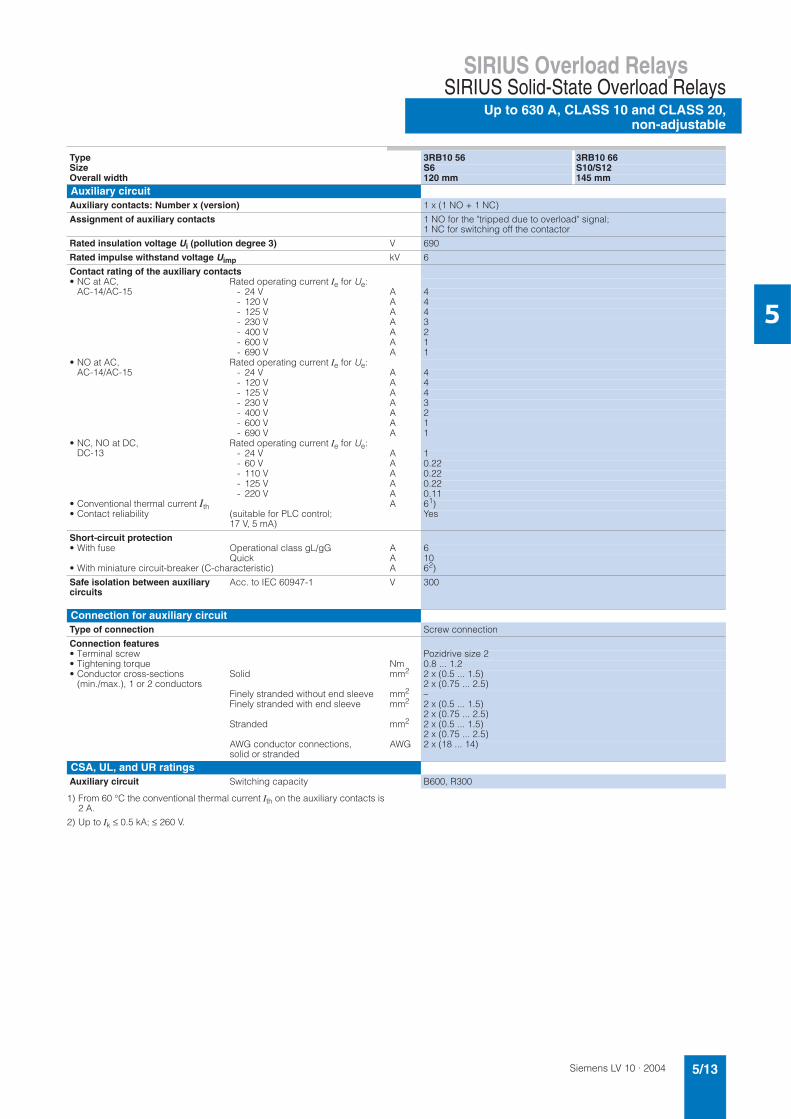
Siemens LV 10 · 2004 5/13
SIRIUS Overload RelaysSIRIUS Solid-State Overload Relays
Up to 630 A, CLASS 10 and CLASS 20,non-adjustable
5
1) From 60 °C the conventional thermal current Ith on the auxiliary contacts is 2 A.
2) Up to Ik ≤ 0.5 kA; ≤ 260 V.
Type 3RB10 56 3RB10 66 Size S6 S10/S12Overall width 120 mm 145 mmAuxiliary circuitAuxiliary contacts: Number x (version) 1 x (1 NO + 1 NC)
Assignment of auxiliary contacts 1 NO for the "tripped due to overload" signal; 1 NC for switching off the contactor
Rated insulation voltage Ui (pollution degree 3) V 690
Rated impulse withstand voltage Uimp kV 6
Contact rating of the auxiliary contacts• NC at AC,
AC-14/AC-15 Rated operating current Ie for Ue:
- 24 V A 4- 120 V A 4- 125 V A 4- 230 V A 3- 400 V A 2- 600 V A 1- 690 V A 1
• NO at AC, AC-14/AC-15
Rated operating current Ie for Ue:- 24 V A 4- 120 V A 4- 125 V A 4- 230 V A 3- 400 V A 2- 600 V A 1- 690 V A 1
• NC, NO at DC, DC-13
Rated operating current Ie for Ue:- 24 V A 1- 60 V A 0.22- 110 V A 0.22- 125 V A 0.22- 220 V A 0.11
• Conventional thermal current Ith A 61)• Contact reliability (suitable for PLC control;
17 V, 5 mA)Yes
Short-circuit protection • With fuse Operational class gL/gG A 6
Quick A 10• With miniature circuit-breaker (C-characteristic) A 62)
Safe isolation between auxiliary circuits
Acc. to IEC 60947-1 V 300
Connection for auxiliary circuitType of connection Screw connection
Connection features• Terminal screw Pozidrive size 2• Tightening torque Nm 0.8 ... 1.2• Conductor cross-sections
(min./max.), 1 or 2 conductorsSolid mm2 2 x (0.5 ... 1.5)
2 x (0.75 ... 2.5)Finely stranded without end sleeve mm2 –Finely stranded with end sleeve mm2 2 x (0.5 ... 1.5)
2 x (0.75 ... 2.5)Stranded mm2 2 x (0.5 ... 1.5)
2 x (0.75 ... 2.5)AWG conductor connections, solid or stranded
AWG 2 x (18 ... 14)
CSA, UL, and UR ratingsAuxiliary circuit Switching capacity B600, R300
Siemens LV 10 · 20045/14
SIRIUS Overload Relays
Up to 630 A, CLASS 10 and CLASS 20,non-adjustable
SIRIUS Solid-State Overload Relays
5
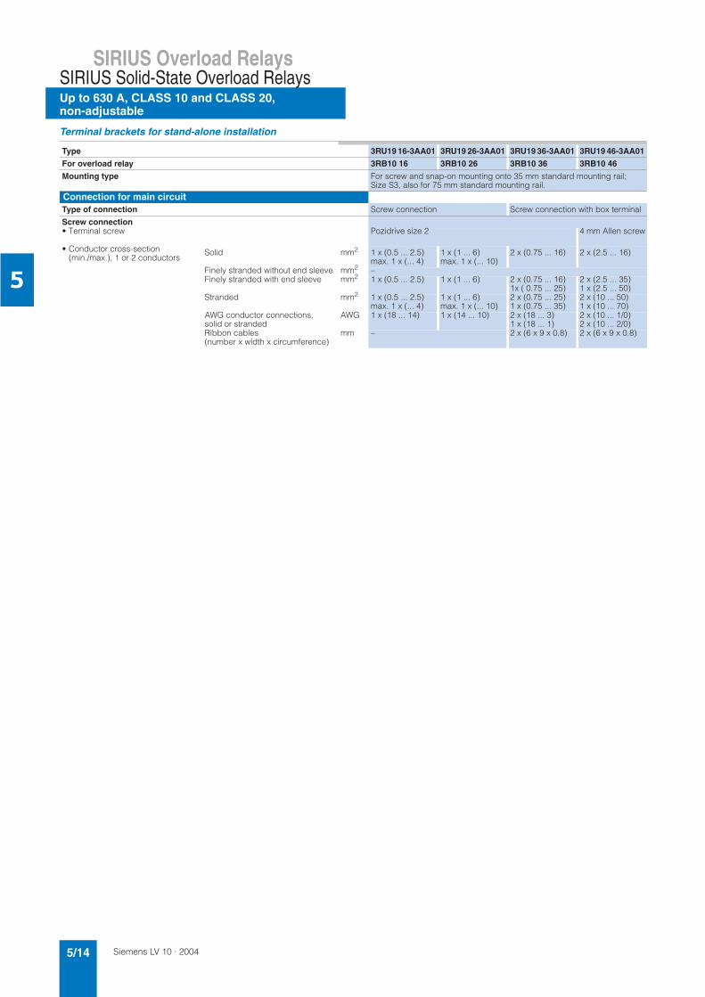
Terminal brackets for stand-alone installation
Type 3RU19 16-3AA01 3RU19 26-3AA01 3RU19 36-3AA01 3RU19 46-3AA01
For overload relay 3RB10 16 3RB10 26 3RB10 36 3RB10 46
Mounting type For screw and snap-on mounting onto 35 mm standard mounting rail; Size S3, also for 75 mm standard mounting rail.
Connection for main circuitType of connection Screw connection Screw connection with box terminal
Screw connection• Terminal screw Pozidrive size 2 4 mm Allen screw
• Conductor cross-section(min./max.), 1 or 2 conductors
Solid mm2 1 x (0.5 ... 2.5) max. 1 x (... 4)
1 x (1 ... 6) max. 1 x (... 10)
2 x (0.75 ... 16) 2 x (2.5 ... 16)
Finely stranded without end sleeve mm2 –Finely stranded with end sleeve mm2 1 x (0.5 ... 2.5) 1 x (1 ... 6) 2 x (0.75 ... 16)
1x ( 0.75 ... 25)2 x (2.5 ... 35)1 x (2.5 ... 50)
Stranded mm2 1 x (0.5 ... 2.5) max. 1 x (... 4)
1 x (1 ... 6) max. 1 x (... 10)
2 x (0.75 ... 25)1 x (0.75 ... 35)
2 x (10 ... 50)1 x (10 ... 70)
AWG conductor connections, solid or stranded
AWG 1 x (18 ... 14) 1 x (14 ... 10) 2 x (18 ... 3)1 x (18 ... 1)
2 x (10 ... 1/0)2 x (10 ... 2/0)
Ribbon cables(number x width x circumference)
mm – 2 x (6 x 9 x 0.8) 2 x (6 x 9 x 0.8)
Siemens LV 10 · 2004 5/15
SIRIUS Overload RelaysSIRIUS Solid-State Overload Relays
Up to 630 A, CLASS 10 and CLASS 20,non-adjustable
5
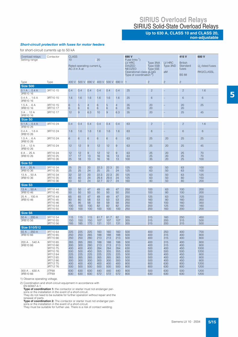
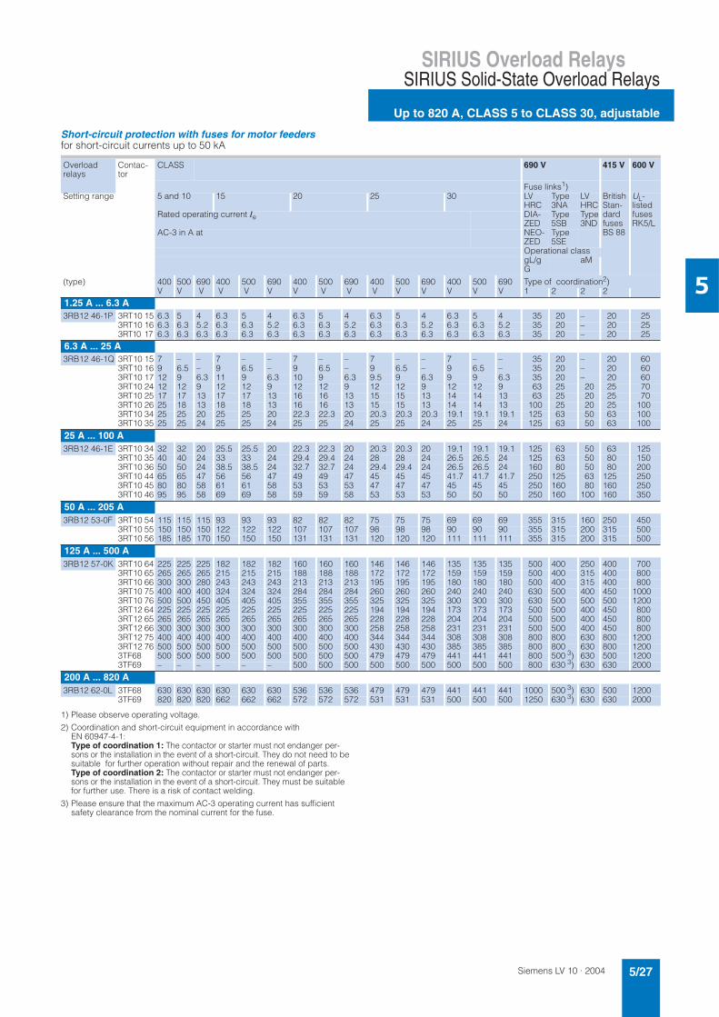
Short-circuit protection with fuses for motor feeders
for short-circuit currents up to 50 kA
1) Observe operating voltage.
2) Coordination and short-circuit equipment in accordance with EN 60947-4-1:Type of coordination 1: the contactor or starter must not endanger per-sons or the installation in the event of a short-circuit.They do not need to be suitable for further operation without repair and the renewal of parts. Type of coordination 2: The contactor or starter must not endanger per-sons or the installation in the event of a short-circuit. They must be suitable for further use. There is a risk of contact welding.
Overload relays Contactor CLASS 690 V 415 V 600 VSetting range 10 20 Fuse links 1)
LV HRC Type 3NA LV HRC BritishStandard fuses
BS 88
Rated operating current Ie DIAZED Type 5SB Type 3ND UL-listed fusesAC-3 in A at NEOZED Type 5SE
Operational class gL/gGType of coordination 2)
aM RK5/CLASSL
Type Type 400 V 500 V 690 V 400 V 500 V 690 V 1 2 2 2
Size S000.1 A ... 0.4 A 3RT10 15 0.4 0.4 0.4 0.4 0.4 0.4 25 2 – 2 1.63RB10 16
0.4 A ... 1.6 A 3RT10 15 1.6 1.6 1.6 1.6 1.6 1.6 25 6 – 6 63RB10 16
1.5 A ... 6 A 3RT10 15 6 5 4 6 5 4 35 20 – 20 253RB10 16 3RT10 17 6 6 6 6 6 6 35 20 20
3 A ... 12 A 3RT10 17 12 9 6.3 10 9 6.3 35 20 – 25 453RB10 16
Size S00.1 A ... 0.4 A 3RT10 24 0.4 0.4 0.4 0.4 0.4 0.4 63 2 – 2 1.63RB10 26
0.4 A ... 1.6 A 3RT10 24 1.6 1.6 1.6 1.6 1.6 1.6 63 6 – 6 63RB10 26
1.5 A ... 6 A 3RT10 24 6 6 6 6 6 6 63 25 20 25 253RB10 26
3 A ... 12 A 3RT10 24 12 12 9 12 12 9 63 25 20 25 453RB10 26
6 A ... 25 A 3RT10 24 12 12 9 12 12 9 63 25 20 25 703RB10 26 3RT10 25 17 17 13 16 16 13 63 25 20 25 70
3RT10 26 25 18 13 16 16 13 100 35 20 25 100
Size S26 A ... 25 A 3RT10 34 25 25 20 22.3 22.3 20 125 63 50 63 1003RB10 36 3RT10 35 25 25 24 25 25 24 125 63 50 63 100
13 A ... 50 A 3RT10 34 32 32 20 22.3 22.3 20 125 63 50 63 1253RB10 36 3RT10 35 40 40 24 29.4 29.4 24 125 63 50 80 150
3RT10 36 50 50 24 32.7 32.7 24 160 80 50 80 200
Size S313 A ... 50 A 3RT10 44 50 50 47 49 49 47 250 100 63 100 2003RB10 46 3RT10 45 50 50 50 50 50 50 250 100 80 100 200
25 A ... 100 A 3RT10 44 65 65 47 49 49 47 250 125 63 125 2503RB10 46 3RT10 45 80 80 58 53 53 53 250 160 80 160 350
3RT10 46 95 95 58 59 59 58 250 160 100 160 3503RT10 54 100 100 100 82 82 82 250 200 125 160 1603RT10 55 100 100 100 100 100 100 250 200 160 200 200
Size S650 A ... 200 A 3RT10 54 115 115 115 81.7 81.7 82 355 315 160 250 4503RB10 56 3RT10 55 150 150 150 107 107 107 355 315 200 315 500
3RT10 56 185 185 170 131 131 131 355 315 200 315 500
Size S10/S1255 A ... 250 A 3RT10 64 225 225 225 160 160 160 500 400 250 400 7003RB10 66 3RT10 65 250 250 265 188 188 188 500 400 315 400 800
3RT10 66 250 250 280 213 213 213 500 400 315 400 800
200 A ... 540 A 3RT10 65 265 265 265 188 188 188 500 400 315 400 8003RB10 66 3RT10 66 300 300 280 213 213 213 500 400 315 400 800
3RT10 75 400 400 400 284 284 284 630 500 400 450 10003RT10 76 500 500 450 355 355 355 630 500 500 500 12003RT12 64 225 225 225 225 225 225 500 500 400 450 8003RT12 65 265 265 265 265 265 265 500 500 400 450 8003RT12 66 300 300 300 300 300 300 500 500 400 450 8003RT12 75 400 400 400 400 400 400 800 800 630 800 12003RT12 76 500 500 500 500 500 500 800 800 630 800 1200
300 A ... 630 A 3TF68 630 630 630 440 440 440 800 500 630 500 12003RB10 66 3TF69 630 630 630 572 572 572 800 630 630 630 1200
Siemens LV 10 · 20045/16
SIRIUS Overload Relays
Up to 630 A, CLASS 10 and CLASS 20,non-adjustable
SIRIUS Solid-State Overload Relays
5
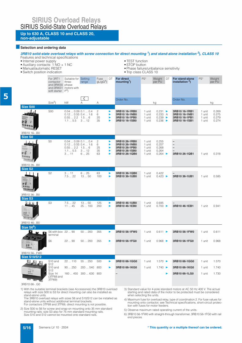
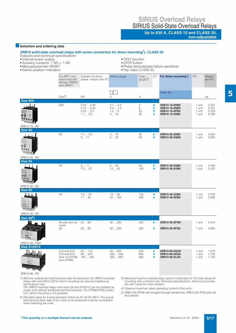
Selection and ordering data
3RB10 solid-state overload relays with screw connection for direct mounting 1) and stand-alone installation 2), CLASS 10Features and technical specifications• Internal power supply• Auxiliary contacts: 1 NO + 1 NC• Manual/automatic RESET• Switch position indication
• TEST function• STOP button• Phase failure/unbalance sensitivity• Trip class CLASS 10
1) With the suitable terminal brackets (see Accessories) the 3RB10 overload relays with size S00 to S3 for direct mounting can also be installed as stand-alone units. The 3RB10 overload relays with sizes S6 and S10/S12 can be installed as stand-alone units without additional terminal brackets. For contactors 3TF68 and 3TF69, direct mounting is not possible.
2) Size S00 to S6 for screw and snap-on mounting onto 35 mm standard mounting rails; size S3 also for 75 mm standard mounting rails. Size S10 and S12 cannot be mounted onto standard rails.
3) Standard value for 4-pole standard motors at AC 50 Hz 400 V. The actual starting and rated data of the motor to be protected must be considered when selecting the units.
4) Maximum fuse for overload relay, type of coordination 2. For fuse values for mounting onto contactor, see Technical specifications, short-circuit protec-tion with fuses for motor feeders.
5) Observe maximum rated operating current of the units.
6) 3RB10 56-1FW0 with straight-through transformer, 3RB10 56-1FG0 with rail end pieces.
For 3RT1 contactorand 3RW30 and 3RW31 soft starter
Suitable for three-phasemotors with P3)
Settingrange
FusegL/gG4)
DT For direct mounting1)
PS* Weight per PU
DT For stand-alone installation 2)
PS* Weight per PU
Order No. Order No.Size5) kW A A kg kg
Size S00
3RB10 16-..B0
S00 0.04 ... 0.09 0.1 ... 0.4 2 3RB10 16-1RB0 1 unit 0.231 3RB10 16-1RB1 1 unit 0.2690.12 ... 0.55 0.4 ... 1.6 6 3RB10 16-1NB0 1 unit 0.233 A 3RB10 16-1NB1 1 unit 0.2750.55 ... 2.2 1.5 ... 6 20 3RB10 16-1PB0 1 unit 0.239 3RB10 16-1PB1 1 unit 0.2791.1 ... 5.5 3 ... 12 35 3RB10 16-1SB0 1 unit 0.236 3RB10 16-1SB1 1 unit 0.274
Size S0
3RB10 26-..B0
S0 0.04 ... 0.09 0.1 ... 0.4 2 3RB10 26-1RB0 1 unit 0.255 –0.12 ... 0.55 0.4 ... 1.6 6 3RB10 26-1NB0 1 unit 0.257 –0.55 ... 2.2 1.5 ... 6 25 3RB10 26-1PB0 1 unit 0.268 –1.1 ... 5.5 3 ... 12 35 3RB10 26-1SB0 1 unit 0.264 –3 ... 11 6 ... 25 63 3RB10 26-1QB0 1 unit 0.264 3RB10 26-1QB1 1 unit 0.318
Size S2
3RB10 36-..B0
S2 3 ... 11 6 ... 25 63 3RB10 36-1QB0 1 unit 0.422 –7.5 ... 22 13 ... 50 100 3RB10 36-1UB0 1 unit 0.423 3RB10 36-1UB1 1 unit 0.585
Size S3
3RB10 46-..B0
S3 7.5 ... 22 13 ... 50 125 3RB10 46-1UB0 1 unit 0.695 –11 ... 45 25 ... 100 200 3RB10 46-1EB0 1 unit 0.700 3RB10 46-1EB1 1 unit 0.941
Size S66)
3RB10 56-..FW0
S6 with box terminal
22 ... 90 50 ... 200 355 3RB10 56-1FW0 1 unit 0.611 3RB10 56-1FW0 1 unit 0.611
S6 22 ... 90 50 ... 200 355 3RB10 56-1FG0 1 unit 0.968 3RB10 56-1FG0 1 unit 0.968
Size S10/S12
3RB10 66-..G0
S10 and S12
22 ... 110 55 ... 250 500 3RB10 66-1GG0 1 unit 1.570 3RB10 66-1GG0 1 unit 1.570
S10 and S12
90 ... 250 200 ... 540 800 3RB10 66-1KG0 1 unit 1.740 3RB10 66-1KG0 1 unit 1.740
Size 14 (3TF68 and 3TF69)
160 ... 450 300 ... 630 800 – 3RB10 66-1LG0 1 unit 1.730
* This quantity or a multiple thereof can be ordered.
Siemens LV 10 · 2004 5/17
SIRIUS Overload RelaysSIRIUS Solid-State Overload Relays
Up to 630 A, CLASS 10 and CLASS 20,non-adjustable
5
Selection and ordering data
3RB10 solid-state overload relays with screw connection for direct mounting1), CLASS 20Features and technical specifications • Internal power supply • Auxiliary contacts: 1 NO + 1 NC • Manual/automatic RESET • Switch position indication
• TEST function • STOP button • Phase failure/phase failure sensitivity • Trip class CLASS 20
1) With the suitable terminal brackets (see Accessories), the 3RB10 overload relays with size S00 to S3 for direct mounting can also be installed as stand-alone units. The 3RB10 overload relays with sizes S6 and S10/S12 can be installed as single units without additional terminal brackets. For 3TF68/3TF69 contac-tors, direct mounting is not possible.
2) Standard value for 4-pole standard motors at AC 50 Hz 400 V. The actual starting and rated data of the motor to be protected must be considered when selecting the units.
3) Maximum fuse for overload relay, type of coordination 2. For fuse values for mounting onto contactor see Technical specifications, short-circuit protec-tion with fuses for motor feeders.
4) Observe maximum rated operating current of the units.
5) 3RB10 56-2FW0 with straight-through transformer, 3RB10 56-2FG0 with rail end pieces.
For 3RT1 con-tactor and soft starters 3RW30 and 3RW31
Suitable for three-phase motors with P2)
Setting range FusegL/gG3)
DT For direct mounting1) PS* Weight per PU
Order No.
Size4) kW A A kg
Size S00
3RB10 16-..B0
S00 0.04 ... 0.09 0.1 ... 0.4 2 3RB10 16-2RB0 1 unit 0.2310.12 ... 0.55 0.4 ... 1.6 6 3RB10 16-2NB0 1 unit 0.2310.55 ... 2.2 1.5 ... 6 20 3RB10 16-2PB0 1 unit 0.2391.1 ... 5.5 3 ... 12 35 3RB10 16-2SB0 1 unit 0.236
Size S0
3RB10 26-..B0
S0 1.1 ... 5.5 3 ... 12 35 3RB10 26-2SB0 1 unit 0.2603 ... 11 6 ... 25 63 3RB10 26-2QB0 1 unit 0.263
Size S2
3RB10 36-..B0
S2 3 ... 11 6 ... 25 63 3RB10 36-2QB0 1 unit 0.4267.5 ... 22 13 ... 50 100 3RB10 36-2UB0 1 unit 0.422
Size S3
3RB10 46-..B0
S3 7.5 ... 22 13 ... 50 125 3RB10 46-2UB0 1 unit 0.70011 ... 45 25 ... 100 200 3RB10 46-2EB0 1 unit 0.698
Size S65)
3RB10 56-..FW0
S6 with box ter-minal
22 ... 90 50 ... 200 355 3RB10 56-2FW0 1 unit 0.615
S6 22 ... 90 50 ... 200 355 3RB10 56-2FG0 1 unit 0.963
Size S10/S12
3RB10 66-..B0
S10 and S12 22 ... 110 55 ... 250 500 3RB10 66-2GG0 1 unit 1.570S10 and S12 90 ... 250 200 ... 540 800 3RB10 66-2KG0 1 unit 1.740Size 14 (3TF68 and 3TF69)
160 ... 450 300 ... 630 800 3RB10 66-2LG0 1 unit 1.740
* This quantity or a multiple thereof can be ordered.
Siemens LV 10 · 20045/18
SIRIUS Overload Relays
Up to 630 A, CLASS 10 and CLASS 20,non-adjustable
SIRIUS Solid-State Overload Relays
5
Accessories
The following accessories are available for the 3RB10 solid-state overload relays• For the four overload relay sizes S00 to S3 one terminal bracket
each for stand-alone installation• One electrical remote RESET module in three voltage variants
for all sizes. • One mechanical remote RESET module for all sizes• One cable release for resetting devices which are difficult to
access (for all sizes)• One sealable cover for the current adjustment screw which can
also be used to block the selector switch "manual/automatic RESET" (for all sizes).
• Box terminals for sizes S6 and S10/S12 as well as• Terminal covers for sizes S2 to S10/S12.
The accessories for the overload relay sizes S00 to S3 can also be used for the thermal overload relays (exception: sealable cover).
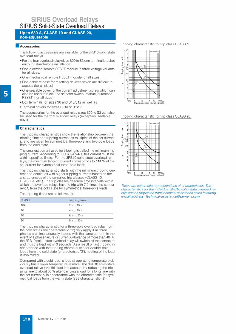
Characteristics
The tripping characteristics show the relationship between the tripping time and tripping current as multiples of the set current Ie and are given for symmetrical three-pole and two-pole loads from the cold state.
The smallest current used for tripping is called the minimum trip-ping current. According to IEC 60947-4-1, this current must be within specified limits. For the 3RB10 solid-state overload re-lays, the minimum tripping current corresponds to 114 % of the set current for symmetrical three-pole loads.
The tripping characteristic starts with the minimum tripping cur-rent and continues with higher tripping currents based on the characteristics of the so-called trip classes (CLASS 10, CLASS 20 etc.). The trip classes describe time intervals within which the overload relays have to trip with 7.2 times the set cur-rent Ie from the cold state for symmetrical three-pole loads.
The tripping times are as follows for:
The tripping characteristic for a three-pole overload relay from the cold state (see characteristic "1") only apply if all three phases are simultaneously loaded with the same current. In the event of a phase failure or current unbalance of more than 40 %, the 3RB10 solid-state overload relay will switch off the contactor and thus the load within 3 seconds. As a result of fast tripping in accordance with the tripping characteristic for double-pole loads from the cold state (characteristic "3"), heating of the load is minimized.
Compared with a cold load, a load at operating temperature ob-viously has a lower temperature reserve. The 3RB10 solid-state overload relays take this fact into account by reducing the trip-ping time to about 30 % after carrying a load for a long time with the set current Ie in accordance with the characteristic for sym-metrical loads from the warm state (see characteristic "2").
Tripping characteristic for trip class CLASS 10
Tripping characteristic for trip class CLASS 20
These are schematic representations of characteristics. The characteristics for the individual 3RB10 solid-state overload re-lays can be requested from technical assistance at the following e-mail address: [email protected]
CLASS Tripping times
10A 2 s ... 10 s
10 4 s ... 10 s
20 6 s ... 20 s
30 9 s ... 30 s
10
6
4
64
2
1 2 4 10x e
sm
in
NSB00293
0,61
6
810
5012
20
401
2
3
A
Trip
ping
tim
e
Tripping current (mean values)
10
6
4
64
2
1 2 4 10x e
sm
inNSB00294
0,61
6
810
5012
20
40
1
2
3
AT
rippi
ng ti
me
Tripping current (mean values)
Siemens LV 10 · 2004 5/19
SIRIUS Overload RelaysSIRIUS Solid-State Overload Relays
Up to 630 A, CLASS 10 and CLASS 20,non-adjustable
5
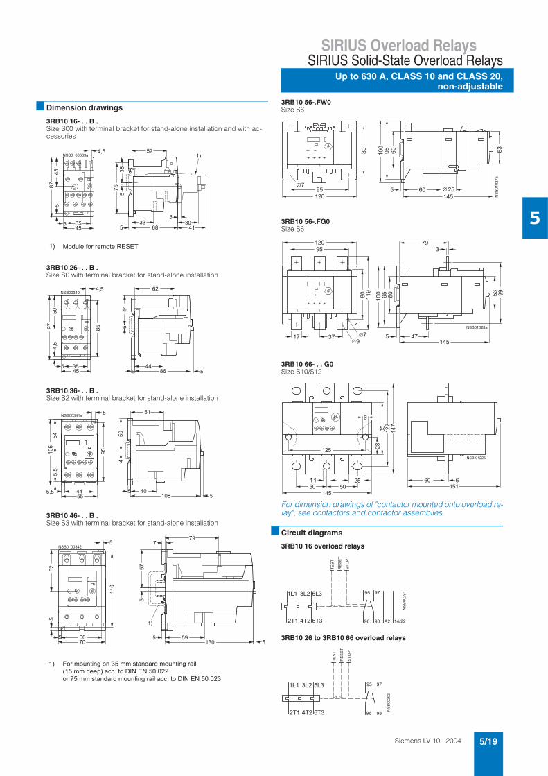
Dimension drawings
3RB10 16- . . B .Size S00 with terminal bracket for stand-alone installation and with ac-cessories
3RB10 26- . . B .Size S0 with terminal bracket for stand-alone installation
3RB10 36- . . B .Size S2 with terminal bracket for stand-alone installation
3RB10 46- . . B .Size S3 with terminal bracket for stand-alone installation
3RB10 56-.FW0Size S6
3RB10 56-.FG0Size S6
3RB10 66- . . G0Size S10/S12
For dimension drawings of "contactor mounted onto overload re-lay", see contactors and contactor assemblies.
Circuit diagrams
3RB10 16 overload relays
3RB10 26 to 3RB10 66 overload relays
2 &
%
3
%
! 0 ' 4 4 + 2
NSB00340
445
5 35
85
45
4,5
9750
4,5
446
86
62
5
2
&
%
%
% &
%
2 5 / # / !6 2 ) 7 4 % # / ! ) 7 4
Siemens LV 10 · 20045/20
SIRIUS Overload Relays
Up to 820 A, CLASS 5 to CLASS 30, adjustable
SIRIUS Solid-State Overload Relays
5
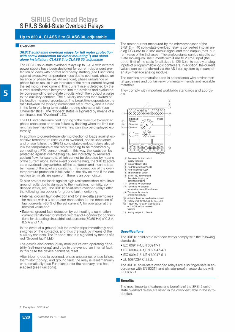
Overview
3RB12 solid-state overload relays for full motor protection with screw connection for direct mounting 1) and stand-alone installation, CLASS 5 to CLASS 30, adjustable
The 3RB12 solid-state overload relays up to 820 A with external power supply have been designed for current-dependent pro-tection of loads with normal and heavy starting (see Functions) against excessive temperature rises due to overload, phase un-balance or phase failure. An overload, phase unbalance or phase failure results in an increase of the motor current beyond the set motor rated current. This current rise is detected by the current transformers integrated into the devices and evaluated by corresponding solid-state circuits which then output a pulse to the auxiliary contacts. The auxiliary contacts then switch off the load by means of a contactor. The break time depends on the ratio between the tripping current and set current Ie and is stored in the form of a long-term stable tripping characteristic (see Characteristics). The "tripped" status is signaled by means of a continuous red "Overload" LED.
The LED indicates imminent tripping of the relay due to overload, phase unbalance or phase failure by flashing when the limit cur-rent has been violated. This warning can also be displayed ex-ternally.
In addition to current-dependent protection of loads against ex-cessive temperature rises due to overload, phase unbalance and phase failure, the 3RB12 solid-state overload relays also al-low the temperature of the motor winding to be monitored by connecting a PTC sensor circuit. In this way, the loads can be protected against overheating caused indirectly by reduced coolant flow, for example, which cannot be detected by means of the current alone. In the event of overheating, the 3RB12 solid-state overload relay switches off the contactor, and thus the load, by means of the auxiliary contacts. The connection of the over-temperature protection is fail-safe i.e. the device trips if the con-nection terminals are open or if there is an open circuit.
To also protect the loads against high-resistance short-circuits or ground faults due to damage to the insulation, humidity, con-densed water, etc., the 3RB12 solid-state overload relays offer the following two options for ground fault monitoring:• Internal ground fault detection (not for star-delta assemblies)
for motors with a 3-conductor connection for the detection of fault currents >30 % of the set current Ie for operation at the nominal value and
• External ground fault detection by connecting a summation current transformer for motors with 3 and 4-conductor connec-tions for detecting sinusoidal fault currents (50/60 Hz) of 0.3 A, 0.5 A and 1 A.
In the event of a ground fault the device trips immediately and switches off the contactor, and thus the load, by means of the auxiliary contacts. The "tripped" status is signaled by means of a red "Ground fault" LED.
The device also continuously monitors its own operating capa-bility (self-monitoring) and trips in the event of an internal fault. In this case the device cannot be reset.
After tripping due to overload, phase unbalance, phase failure, thermistor tripping, and ground fault, the relay is reset manually or automatically (see Functions) after the recovery time has elapsed (see Functions).
The motor current measured by the microprocessor of the 3RB12..-...40 solid-state overload relay is converted into an an-alog DC 4 mA to 20 mA output signal and then output (max. cur-rent value of the 3 phases). The analog signal can be used to ac-tuate moving-coil instruments with 4 mA to 20 mA input (the upper limit of the scale for all sizes is 125 %) or to supply analog inputs of programmable logic controllers. In addition, the current values can be transferred via the AS-i bus system by means of an AS-Interface analog module.
The devices are manufactured in accordance with environmen-tal guidelines and contain environmentally friendly and reusable materials.
They comply with important worldwide standards and approv-als.
Specifications
The 3RB12 solid-state overload relays comply with the following standards:• IEC 60947-1/EN 60947-1• IEC 60947-4-1/EN 60947-4-1• IEC 60947-5-1/EN 60947-5-1• UL 508/CSA C 22.2.
The 3RB12 solid-state overload relays are also finger-safe in ac-cordance with EN 50274 and climate-proof in accordance with IEC 60721.
Benefits
The most important features and benefits of the 3RB12 solid-state overload relays are listed in the overview table in the intro-duction.
1) Exception: 3RB12 46.
! "
! !
" # #
$
$ %
& ' ( ) * +
( , , - (
. . ! /
. . ! /
. . ! /
! " ! ! 0
" ) "
* & ' ( ' , , ' -
* ) ' , , ' -
& ' ( ) * & ' (
& ' ( ) 1
( & & ' + ( ) &
& ' ( ) &
& ' + ! !
2 ( 3 0 ) & +
3 0 ) 4 4 5 5 5 4
" ) * ) ' , , ' -
" )
6 ' -
- , 5 5 5 &
Siemens LV 10 · 2004 5/21
SIRIUS Overload RelaysSIRIUS Solid-State Overload Relays
Up to 820 A, CLASS 5 to CLASS 30, adjustable
5
Area of application
Fields of application
The 3RB12 solid-state overload relays have been designed for the protection of three-phase asynchronous and single-phase AC motors.
If single-phase AC motors are to be protected with the 3RB12 solid-state overload relay, the microprocessor must only monitor one phase conductor. For this reason, the main circuits must be connected to the current transformer as described in the oper-ating manual for the 3RB12 solid-state overload relay.
Ambient conditions
The devices are insensitive to external influences such as shocks, corrosive environments, ageing, and temperature changes.
For the temperature range from –25 °C to +70 °C, the 3RB12 solid-state overload relays compensate the temperature in ac-cordance with IEC 60947-4-1.
"Increased safety" type of protection EEx e
The 3RB12 solid-state overload relays comply with the regula-tions for the overload protection of explosion-proof motors with "increased safety" type of protection EEx e EN 50019.
For tripping units with DC operation, electrical isolation must be ensured by means of a battery unit or safety transformer in ac-cordance with EN 60742.
When using 3RB12..-....1 solid-state overload relays (no change of switching status of auxiliary contacts in the event of control supply voltage failure) for the protection of EEx e motors, sepa-rate monitoring of the control supply voltage is recommended.
The basic safety and health requirements are fulfilled by compli-ance with• EN 60947-1• EN 60947-4-1• EN 60947-5-1• DIN VDE 0660-302• DIN VDE 0660-303• EN 60079-14
EU type test certificates for Category (2) G1) with the number• PTB 01 ATEX 3220 has been issued.
Design
Mounting options
The 3RB12 solid-state overload relays can be installed as single units or mounted directly onto the contactors with the help of connecting bars (exception: 3RB12 with 70 mm overall width). For more information on the mounting options, please consult the technical specifications as well as the selection and ordering data.
Connections
The 3RB12 solid-state overload relays with 120 mm, 145 mm, and 230 mm width are fitted with a bus connection for the main circuits. In contrast, the main circuits for the 70 mm 3RB12 over-load relay are simply routed short-circuit proof through the straight-through transformer of the relay directly to the terminals of the contactor. For motor rated currents IN which are lower than 1.25 A, the supply conductors for the motors can be routed mul-tiple times (n times) through the openings for each phase. The set current Ie for multiple routing of the motor supply conductors are calculated with the following formula: Ie = n x IN with n ≤ 5.1) Please ask for approvals for dusty environments.
The auxiliary contact terminals of all 3RB12 overload relays have screw connections.
For more information on the different connection options please consult the technical specifications as well as the selection and ordering data.
Overload relays in star-delta assemblies
When overload relays are used in combination with star-delta as-semblies it must be noted that only 0.58 times the motor current flows through the line contactor. An overload relay mounted onto the line contactor must be set to 0.58 times the motor current.
The 3RB12 solid-state overload relays with internal ground fault detection are not suited for use with star-delta assemblies be-cause transient current peaks are generated during the switch-over from star to delta operation. These can trigger ground fault detection.
Operation with frequency converter
The 3RB12 solid-state overload relays are suitable for frequen-cies of 50/60 Hz as well as the associated harmonics. This per-mits the 3RB12 overload relays to be used on the incoming side of the frequency converter. If a motor contactor is required on the outgoing side of the fre-quency converter, Siemens recommends the 3RN thermistor motor protection devices or the 3RU11 thermal overload relays for this purpose.
Functions
Control circuit
The 3RB12 solid-state overload relays require an external power supply, i.e. an additional supply voltage is necessary. Details about the control circuit can be found in the technical specifica-tions.
Short-circuit protection
Fuses or circuit-breakers must be used for short-circuit protec-tion. Assignments of corresponding short-circuit protection equipment for overload relays with/without contactor can be found in the technical specifications as well as in the selection and ordering data.
Trip classes
The 3RB12 solid-state overload relays are suitable for normal and heavy starting. The required trip class (CLASS 5, 10, 15, 20, 25 or 30) can be adjusted by means of a six-step rotary knob de-pending on the current starting condition. Detailed information about trip classes can be found under "Characteristics".
Phase failure protection
The 3RB12 solid-state overload relays are fitted with phase fail-ure protection (see Characteristics) in order to minimize temper-ature rises of the load during single-phase operation.
Setting
The 3RB12 solid-state overload relay is set to the motor rated current by means of a rotary knob. The scale of the rotary knob is calibrated in ampere.
Manual and automatic reset
The overload relay can be reset by pressing the TEST/RESET button on the device. The overload relay can be reset remotely (remote RESET) by connecting a button to terminals Y1 and Y2 of the 3RB12 solid-state overload relay. In addition, terminals Y1 and Y2 can be jumpered to implement automatic resetting.
The relay can only be reset after the recovery time has elapsed.
Siemens LV 10 · 20045/22
SIRIUS Overload Relays
Up to 820 A, CLASS 5 to CLASS 30, adjustable
SIRIUS Solid-State Overload Relays
5
Recovery time
The recovery time following current-dependent tripping due to overload, phase unbalance or phase failure is 5 min. regardless of the adjusted reset mode. This time, which is stored perma-nently in the microprocessor, allows the load to cool down.
However, in the event of temperature-dependent tripping by means of a connected PTC thermistor sensor circuit, the device
can only be manually or automatically reset once the winding temperature at the installation location of the PTC thermistor has fallen 5 K below its response temperature.
If the 3RB12 solid-state overload relay trips due to a ground fault, it can be switched on again immediately without a recovery time.
TEST function
The combined TEST/RESET button can be used to check whether the relay is working correctly. If the button is pressed up to 2 s, the hardware, LEDs, current detection, thermistor and ground fault input are tested. If the button is pressed up to 5 s, the current transformer, burden, and microprocessor are tested without switching off the motor feeder. After 5 s, the motor feeder is switched off via the output relays of the 3RB12. When the mo-tor feeder is switched off, all functions of the 3RB12 solid-state overload relay have been tested. The function of the current transformer and burden are not tested if there is no voltage on the main circuit.
STOP function
If the TEST/RESET button is pressed, the 3RB12 solid-state over-load relay switches off the contactor and thus the load after 5 s. The load is switched on again via the contactor if the TEST/RESET button is pressed once more.
Display of the operating status
The operating status of the 3RB12 solid-state overload relay is displayed by means of three LEDs:• Green "Ready" LED:
- A continuous green light signals that the overload relay is ready for operation. The 3RB12 overload relay is not ready (LED "OFF") if there is no control supply voltage or if the func-tion test was negative.
• Red "Overload" LED: - A continuous red light signals overload tripping due to current
and/or overload while a flashing red light indicates imminent tripping due to overload (overload warning):
• Red "Ground fault" LED: - A continuous red light signals a ground fault.
Auxiliary contacts
The 3RB12 solid-state overload relay has two outputs, each one has one NO contact and one NC contact. Their assignments de-pend on the version of the device.
A distinction between monostable and bistable 3RB12 solid-state overload relays can be made with respect to the tripping characteristics of the auxiliary contacts in the event of the reduc-tion of the control supply voltage.
The monostable 3RB12 solid-state overload relays will enter the "tripped" state if the control supply voltage fails (> 200 ms), and return to the original state they were in before the control supply voltage failed when the voltage returns. These units are therefore especially suited for plants in which the control voltage is not strictly monitored.
The bistable 3RB12 solid-state overload relays do not change their "tripped" or "not tripped" status if the control voltage fails. The auxiliary contacts only switch over in the event of an over-load and if the supply voltage is present. These units are there-fore especially suited for plants in which the control voltage is monitored separately.
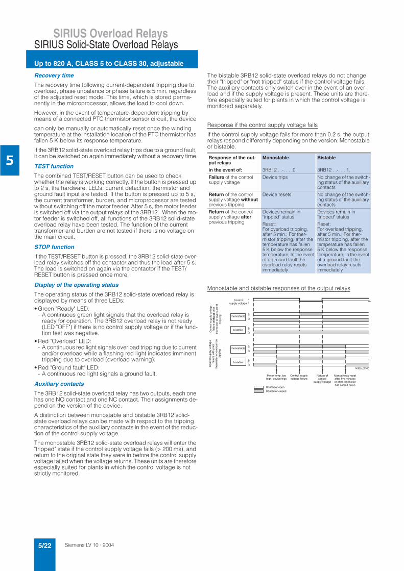
Response if the control supply voltage fails
If the control supply voltage fails for more than 0.2 s, the output relays respond differently depending on the version: Monostable or bistable.
Monostable and bistable responses of the output relays
Response of the out-put relays
Monostable Bistable
in the event of: 3RB12 . .-. . . .0 3RB12 . .-. . . 1.
Failure of the control supply voltage
Device trips No change of the switch-ing status of the auxiliary contacts
Return of the control supply voltage withoutprevious tripping
Device resets No change of the switch-ing status of the auxiliary contacts
Return of the control supply voltage afterprevious tripping
Devices remain in "tripped" status
Reset:For overload tripping, after 5 min.; For ther-mistor tripping, after the temperature has fallen 5 K below the response temperature; In the event of a ground fault the overload relay resets immediately
Devices remain in "tripped" status
Reset:For overload tripping, after 5 min.; For ther-mistor tripping, after the temperature has fallen 5 K below the response temperature; In the event of a ground fault the overload relay resets immediately
$ %
(,,-
)'6'*,'
*&'(+
',,'-
(,,-
)','
*&'(+
',,'-
( , , -
& ( 0
& ( 0
0 ' ( 0
0 ' ( 0
7 & , 5
* ' - * 8 ' + ' , (
( , ,
- ) '
)
+
( , , -
7 " (
) ) ' & ' (
) * & ' (
* ( + 6
+ ,
+ + (
9
9
9
9
Siemens LV 10 · 2004 5/23
SIRIUS Overload RelaysSIRIUS Solid-State Overload Relays
Up to 820 A, CLASS 5 to CLASS 30, adjustable
5
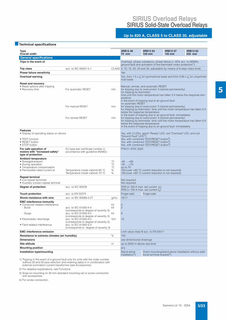
Technical specifications
1) Tripping in the event of a ground fault only for units with the order number suffixes 20 and 30 (see selection and ordering data) or in combination with external summation current transformer (see Accessories).
2) For detailed explanations, see Functions.
3) Snap-on mounting on 35 mm standard mounting rail or screw connection with accessories.
4) For screw connection.
Type 3RB12 46 3RB12 53 3RB12 57 3RB12 62Overall width 70 mm 120 mm 145 mm 230 mmGeneral specificationsTrips in the event of Overload, phase unbalance, phase failure (> 40% acc. to NEMA),
ground fault and activation of the thermistor motor protection1)
Trip class acc. to IEC 60947-4-1 CLASS 5, 10, 15, 20, 25 and 30; adjustable by means of 6-step rotary knob
Phase failure sensitivity Yes
Overload warning Yes, from 1.5 x Ie for symmetrical loads and from 0.85 x Ie for unsymmet-rical loads
Reset and recovery• Reset options after tripping Manual, remote, and automatic RESET• Recovery time For automatic RESET min. for tripping due to overcurrent: 5 (stored permanently)
for tripping by thermistor: time until the motor temperature has fallen 5 K below the response tem-perature in the event of tripping due to an ground fault: no automatic RESET
For manual RESET min. for tripping due to overcurrent: 5 (stored permanently) for tripping by thermistor: time until the motor temperature has fallen 5 K below the response temperature in the event of tripping due to an ground fault: immediately
For remote RESET min. for tripping due to overcurrent: 5 (stored permanently)for tripping by thermistor: time until the motor temperature has fallen 5 K below the response temperature in the event of tripping due to an ground fault: immediately
Features• Display of operating status on device Yes, with 3 LEDs: green "Ready" LED, red "Overload" LED, and red
"Ground Fault" LED"2)• TEST function Yes, with combined TEST/RESET button2)• RESET button Yes, with combined TEST/RESET button2)• STOP button Yes, with combined TEST/RESET button2)
For safe operation of motors with "increased safety" type of protection
EU type test certificate number in accordance with guideline 94/9/EU
PTB 01 ATEX 3220
Ambient temperature• Storage/transport °C -40 ... +80• During operation °C -25 ... +70• Temperature compensation °C up to 70• Permissible rated current at Temperature inside cabinet 60 °C % 100 (over +60 °C current reduction is not required)
Temperature inside cabinet 70 °C % 100 (over +60 °C current reduction is not required)
Repeat terminal • Coil repeat terminals Not required• Auxiliary contact repeat terminal Not required
Degree of protection acc. to IEC 60529 IP20 (≤ 100 A max. set current Ie)IP00 (> 100 A max. set current Ie)
Touch protection acc. to EN 50274 Finger-safe Finger-safe
Shock resistance with sine acc. to IEC 60068-2-27 g/ms 15/11
EMC interference immunity• Conductor-related interference kV 2
- Burst acc. to IEC 61000-4-4 (corresponds to degree of severity 3)
kV 2
- Surge acc. to IEC 61000-4-5 (corresponds to degree of severity 3)
kV 8
• Electrostatic discharge acc. to IEC 61000-4-2 (corresponds to degree of severity 3)
V/m 10
• Field-related interference acc. to IEC 61000-4-3 (corresponds to degree of severity 3)
EMC interference emission Limit value class B acc. to EN 55011
Resistance to extreme climates (air humidity) % 100
Dimensions see dimensional drawings
Site altitude m up to 2000 m above sea level
Mounting position any
Installation type/mounting Stand-alone installation3)
Direct mounting/stand-alone installation without addi-tional terminal bracket4)
Siemens LV 10 · 20045/24
SIRIUS Overload Relays
Up to 820 A, CLASS 5 to CLASS 30, adjustable
SIRIUS Solid-State Overload Relays
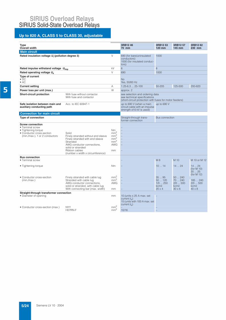
5
Type 3RB12 46 3RB12 53 3RB12 57 3RB12 62Overall width 70 mm 120 mm 145 mm 230 mmMain circuitRated insulation voltage Ui (pollution degree 3) V 690 (for bare/uninsulated
conductors)1000 (for insulated conduc-tors)
1000
Rated impulse withstand voltage Uimp kV 6 8
Rated operating voltage Ue V 690 1000
Type of current• DC No• AC Yes, 50/60 Hz
Current setting A 1.25-6.3 ... 25-100 50-205 125-500 200-820
Power loss per unit (max.) W approx. 2
Short-circuit protection With fuse without contactor see selection and ordering dataWith fuse and contactor see technical specifications
(short-circuit protection with fuses for motor feeders)
Safe isolation between main and auxiliary conducting path
Acc. to IEC 60947-1 up to 690 V (when a main circuit cable with an impulse strength of 6 kV is used)
up to 690 V
Connection for main circuitType of connection Straight-through trans-
former connectionBus connection
Screw connection• Terminal screw –• Tightening torque Nm –• Conductor cross-section
(min./max.), 1 or 2 conductorsSolid mm2 –Finely stranded without end sleeve mm2 –Finely stranded with end sleeve mm2 –Stranded mm2 –AWG conductor connections, solid or stranded
AWG –
Ribbon cables(number x width x circumference)
mm –
Bus connection• Terminal screw – M 8 M 10 M 10 or M 12
• Tightening torque Nm – 10 ... 14 14 ... 24 14 ... 24 (for M 10)20 ... 25 (for M 12)
• Conductor cross-section(min./max.)
Finely stranded with cable lug mm2 – 35 ... 95 50 ... 240Stranded with cable lug mm2 – 50 ... 120 70 ... 240 185 ... 240AWG conductor connections, solid or stranded, with cable lug
AWG – 1/0 ... 250 kcmil
2/0 ... 500 kcmil
2/0 ... 500 kcmil
With connecting bar (max. width) mm – 20 x 4 30 x 6 40 x 8
Straight-through transformer connection• Diameter of opening mm 10 (units ≤ 25 A max. set
current Ie)15 (units with 100 A max. set current Ie)
–
• Conductor cross-section (max.) NYY mm2 – –H07RN-F mm2 10/16 –
Siemens LV 10 · 2004 5/25
SIRIUS Overload RelaysSIRIUS Solid-State Overload Relays
Up to 820 A, CLASS 5 to CLASS 30, adjustable
5
1) The assignment of the auxiliary contacts depends on the order number suffix (see selection and ordering data).
2) On request.
3) Up to Ik ≤ 1000 A.
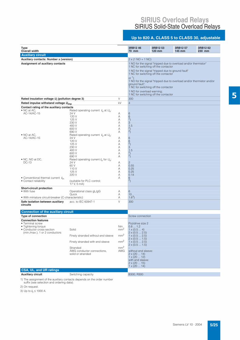
Type 3RB12 46 3RB12 53 3RB12 57 3RB12 62Overall width 70 mm 120 mm 145 mm 230 mmAuxiliary circuitAuxiliary contacts: Number x (version) 2 x (1 NO + 1 NC)
Assignment of auxiliary contacts 1 NO for the signal "tripped due to overload and/or thermistor" 1 NC for switching off the contactor
1 NO for the signal "tripped due to ground fault" 1 NC for switching off the contactor
or 1)1 NO for the signal "tripped due to overload and/or thermistor and/or ground fault"; 1 NC for switching off the contactor
1 NO for overload warning; 1 NC for switching off the contactor
Rated insulation voltage Ui (pollution degree 3) V 300
Rated impulse withstand voltage Uimp kV 4
Contact rating of the auxiliary contacts• NC at AC,
AC-14/AC-15Rated operating current Ie at Ue:24 V A 6120 V A 6125 V A 2)230 V A 3400 V A 1.5600 V A 2)690 V A 2)
• NO at AC, AC-14/AC-15
Rated operating current Ie at Ue:24 V A 6120 V A 6125 V A 2)230 V A 3400 V A 1.5600 V A 2)690 V A 2)
• NC, NO at DC, DC-13
Rated operating current Ie for Ue:24 V A 260 V A 0.55110 V A 0.25125 V A 0.25220 V A 0.14
• Conventional thermal current Ith A 6• Contact reliability (suitable for PLC control;
17 V, 5 mA)2)
Short-circuit protection • With fuse Operational class gL/gG A 6
Quick A 10• With miniature circuit-breaker (C-characteristic) A 1.63)
Safe isolation between auxiliary circuits
acc. to IEC 60947-1 V 300
Connection of the auxiliary circuitType of connection Screw connection
Connection features• Terminal screw Pozidrive size 2• Tightening torque Nm 0.8 ... 1.2• Conductor cross-section
(min./max.), 1 or 2 conductorsSolid mm2 1 x (0.5 ... 4)
2 x (0.5 ... 2.5)Finely stranded without end sleeve mm2 1 x (0.5 ... 2.5)
2 x (0.5 ... 1.5)Finely stranded with end sleeve mm2 1 x (0.5 ... 2.5)
2 x (0.5 ... 1.5)Stranded mm2 –AWG conductor connections, solid or stranded
AWG without end sleeve:2 x (20 ... 14)1 x (20 ... 12)with end sleeve:2 x (20 ... 15)1 x (20 ... 14)
CSA, UL, and UR ratingsAuxiliary circuit Switching capacity B300, R300
Siemens LV 10 · 20045/26
SIRIUS Overload Relays
Up to 820 A, CLASS 5 to CLASS 30, adjustable
SIRIUS Solid-State Overload Relays
5
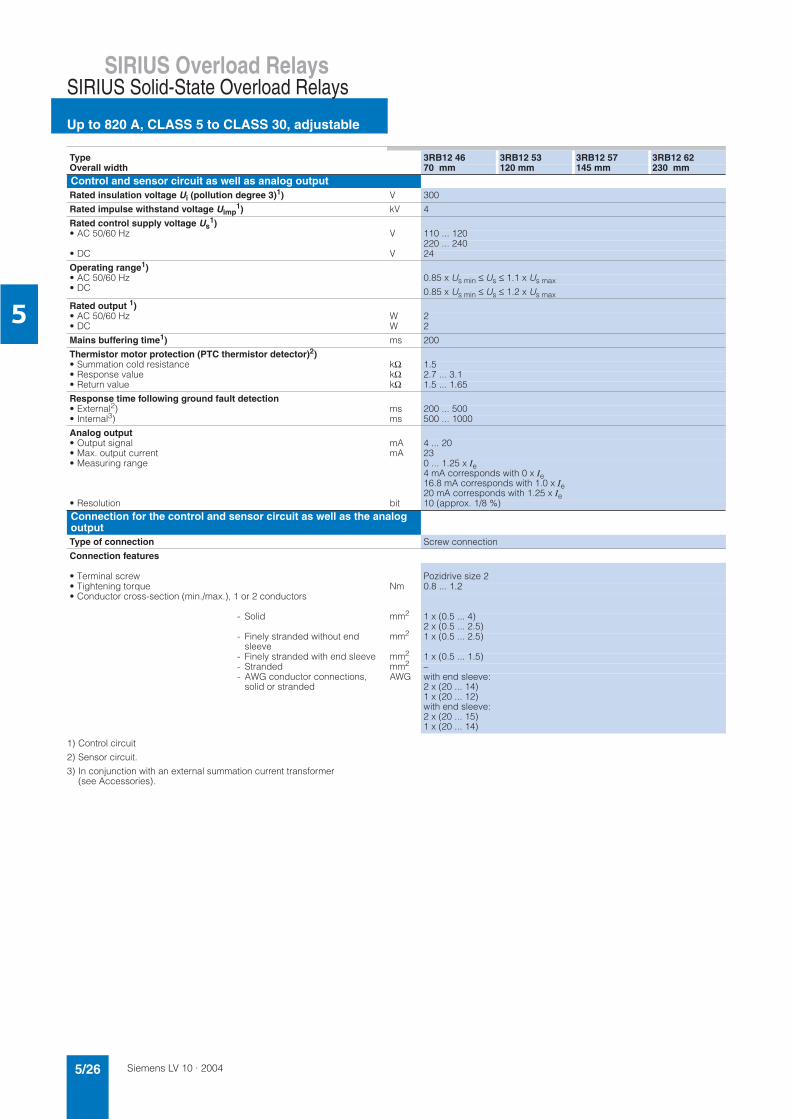
1) Control circuit
2) Sensor circuit.
3) In conjunction with an external summation current transformer (see Accessories).
Type 3RB12 46 3RB12 53 3RB12 57 3RB12 62Overall width 70 mm 120 mm 145 mm 230 mmControl and sensor circuit as well as analog outputRated insulation voltage Ui (pollution degree 3)1) V 300
Rated impulse withstand voltage Uimp1) kV 4
Rated control supply voltage Us1)
• AC 50/60 Hz V 110 ... 120 220 ... 240
• DC V 24
Operating range1)• AC 50/60 Hz 0.85 x Us min ≤ Us ≤ 1.1 x Us max• DC 0.85 x Us min ≤ Us ≤ 1.2 x Us max
Rated output 1)• AC 50/60 Hz W 2• DC W 2
Mains buffering time1) ms 200
Thermistor motor protection (PTC thermistor detector)2)• Summation cold resistance kΩ 1.5• Response value kΩ 2.7 ... 3.1• Return value kΩ 1.5 ... 1.65
Response time following ground fault detection• External2) ms 200 ... 500• Internal3) ms 500 ... 1000
Analog output• Output signal mA 4 ... 20• Max. output current mA 23• Measuring range 0 ... 1.25 x Ie
4 mA corresponds with 0 x Ie16.8 mA corresponds with 1.0 x Ie20 mA corresponds with 1.25 x Ie
• Resolution bit 10 (approx. 1/8 %)Connection for the control and sensor circuit as well as the analog outputType of connection Screw connection
Connection features
• Terminal screw Pozidrive size 2• Tightening torque Nm 0.8 ... 1.2• Conductor cross-section (min./max.), 1 or 2 conductors
- Solid mm2 1 x (0.5 ... 4)2 x (0.5 ... 2.5)
- Finely stranded without end sleeve
mm2 1 x (0.5 ... 2.5)
- Finely stranded with end sleeve mm2 1 x (0.5 ... 1.5)- Stranded mm2 –- AWG conductor connections,
solid or strandedAWG with end sleeve:
2 x (20 ... 14)1 x (20 ... 12)with end sleeve: 2 x (20 ... 15)1 x (20 ... 14)
Siemens LV 10 · 2004 5/27
SIRIUS Overload RelaysSIRIUS Solid-State Overload Relays
Up to 820 A, CLASS 5 to CLASS 30, adjustable
5
Short-circuit protection with fuses for motor feedersfor short-circuit currents up to 50 kA
1) Please observe operating voltage.
2) Coordination and short-circuit equipment in accordance with EN 60947-4-1:Type of coordination 1: The contactor or starter must not endanger per-sons or the installation in the event of a short-circuit. They do not need to be suitable for further operation without repair and the renewal of parts.Type of coordination 2: The contactor or starter must not endanger per-sons or the installation in the event of a short-circuit. They must be suitablefor further use. There is a risk of contact welding.
3) Please ensure that the maximum AC-3 operating current has sufficient safety clearance from the nominal current for the fuse.
Overloadrelays
Contac-tor
CLASS 690 V 415 V 600 V
Fuse links1)Setting range 5 and 10 15 20 25 30 LV
HRCType 3NA
LV HRC
BritishStan-dard fusesBS 88
UL-listedfusesRK5/L
Rated operating current Ie DIA-ZED
Type 5SB
Type 3ND
AC-3 in A at NEO-ZED
Type 5SE
Operational classgL/gG
aM
(type) 400 500 690 400 500 690 400 500 690 400 500 690 400 500 690 Type of coordination2)V V V V V V V V V V V V V V V 1 2 2 2
1.25 A ... 6.3 A3RB12 46-1P 3RT10 15 6.3 5 4 6.3 5 4 6.3 5 4 6.3 5 4 6.3 5 4 35 20 – 20 25
3RT10 16 6.3 6.3 5.2 6.3 6.3 5.2 6.3 6.3 5.2 6.3 6.3 5.2 6.3 6.3 5.2 35 20 – 20 253RT10 17 6.3 6.3 6.3 6.3 6.3 6.3 6.3 6.3 6.3 6.3 6.3 6.3 6.3 6.3 6.3 35 20 – 20 25
6.3 A ... 25 A3RB12 46-1Q 3RT10 15 7 – – 7 – – 7 – – 7 – – 7 – – 35 20 – 20 60
3RT10 16 9 6.5 – 9 6.5 – 9 6.5 – 9 6.5 – 9 6.5 – 35 20 – 20 603RT10 17 12 9 6.3 11 9 6.3 10 9 6.3 9.5 9 6.3 9 9 6.3 35 20 – 20 603RT10 24 12 12 9 12 12 9 12 12 9 12 12 9 12 12 9 63 25 20 25 703RT10 25 17 17 13 17 17 13 16 16 13 15 15 13 14 14 13 63 25 20 25 703RT10 26 25 18 13 18 18 13 16 16 13 15 15 13 14 14 13 100 25 20 25 1003RT10 34 25 25 20 25 25 20 22.3 22.3 20 20.3 20.3 20.3 19.1 19.1 19.1 125 63 50 63 1003RT10 35 25 25 24 25 25 24 25 25 24 25 25 24 25 25 24 125 63 50 63 100
25 A ... 100 A3RB12 46-1E 3RT10 34 32 32 20 25.5 25.5 20 22.3 22.3 20 20.3 20.3 20 19.1 19.1 19.1 125 63 50 63 125
3RT10 35 40 40 24 33 33 24 29.4 29.4 24 28 28 24 26.5 26.5 24 125 63 50 80 1503RT10 36 50 50 24 38.5 38.5 24 32.7 32.7 24 29.4 29.4 24 26.5 26.5 24 160 80 50 80 2003RT10 44 65 65 47 56 56 47 49 49 47 45 45 45 41.7 41.7 41.7 250 125 63 125 2503RT10 45 80 80 58 61 61 58 53 53 53 47 47 47 45 45 45 250 160 80 160 2503RT10 46 95 95 58 69 69 58 59 59 58 53 53 53 50 50 50 250 160 100 160 350
50 A ... 205 A3RB12 53-0F 3RT10 54 115 115 115 93 93 93 82 82 82 75 75 75 69 69 69 355 315 160 250 450
3RT10 55 150 150 150 122 122 122 107 107 107 98 98 98 90 90 90 355 315 200 315 5003RT10 56 185 185 170 150 150 150 131 131 131 120 120 120 111 111 111 355 315 200 315 500
125 A ... 500 A3RB12 57-0K 3RT10 64 225 225 225 182 182 182 160 160 160 146 146 146 135 135 135 500 400 250 400 700
3RT10 65 265 265 265 215 215 215 188 188 188 172 172 172 159 159 159 500 400 315 400 8003RT10 66 300 300 280 243 243 243 213 213 213 195 195 195 180 180 180 500 400 315 400 8003RT10 75 400 400 400 324 324 324 284 284 284 260 260 260 240 240 240 630 500 400 450 10003RT10 76 500 500 450 405 405 405 355 355 355 325 325 325 300 300 300 630 500 500 500 12003RT12 64 225 225 225 225 225 225 225 225 225 194 194 194 173 173 173 500 500 400 450 8003RT12 65 265 265 265 265 265 265 265 265 265 228 228 228 204 204 204 500 500 400 450 8003RT12 66 300 300 300 300 300 300 300 300 300 258 258 258 231 231 231 500 500 400 450 8003RT12 75 400 400 400 400 400 400 400 400 400 344 344 344 308 308 308 800 800 630 800 12003RT12 76 500 500 500 500 500 500 500 500 500 430 430 430 385 385 385 800 800 630 800 12003TF68 500 500 500 500 500 500 500 500 500 479 479 479 441 441 441 800 500 3) 630 500 12003TF69 – – – – – – 500 500 500 500 500 500 500 500 500 800 630 3) 630 630 2000
200 A ... 820 A3RB12 62-0L 3TF68 630 630 630 630 630 630 536 536 536 479 479 479 441 441 441 1000 500 3) 630 500 1200
3TF69 820 820 820 662 662 662 572 572 572 531 531 531 500 500 500 1250 630 3) 630 630 2000
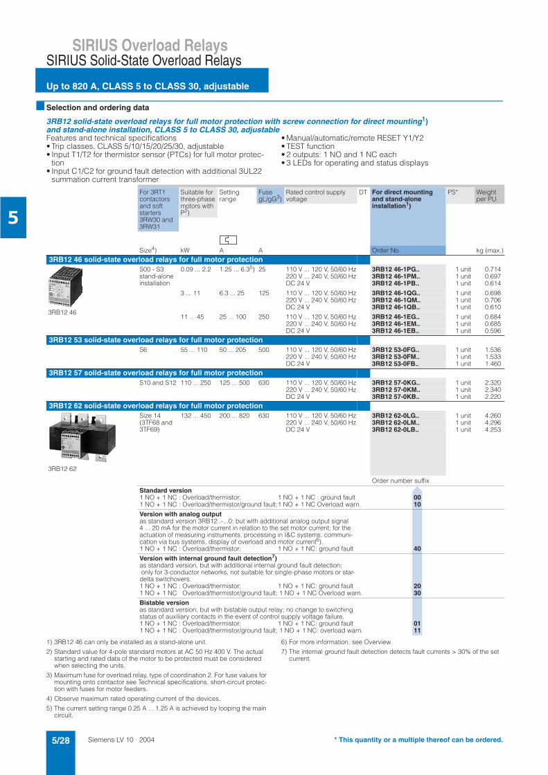
Siemens LV 10 · 20045/28
SIRIUS Overload Relays
Up to 820 A, CLASS 5 to CLASS 30, adjustable
SIRIUS Solid-State Overload Relays
5
Selection and ordering data
3RB12 solid-state overload relays for full motor protection with screw connection for direct mounting1)and stand-alone installation, CLASS 5 to CLASS 30, adjustableFeatures and technical specifications• Trip classes, CLASS 5/10/15/20/25/30, adjustable • Input T1/T2 for thermistor sensor (PTCs) for full motor protec-
tion• Input C1/C2 for ground fault detection with additional 3UL22
summation current transformer
• Manual/automatic/remote RESET Y1/Y2 • TEST function • 2 outputs: 1 NO and 1 NC each • 3 LEDs for operating and status displays
1) 3RB12 46 can only be installed as a stand-alone unit.
2) Standard value for 4-pole standard motors at AC 50 Hz 400 V. The actual starting and rated data of the motor to be protected must be considered when selecting the units.
3) Maximum fuse for overload relay, type of coordination 2. For fuse values for mounting onto contactor see Technical specifications, short-circuit protec-tion with fuses for motor feeders.
4) Observe maximum rated operating current of the devices.
5) The current setting range 0.25 A ... 1.25 A is achieved by looping the main circuit.
6) For more information, see Overview.
7) The internal ground fault detection detects fault currents > 30% of the set current.
For 3RT1 contactors and soft starters 3RW30 and 3RW31
Suitable for three-phase motors with P2)
Settingrange
FusegL/gG3)
Rated control supply voltage
DT For direct mounting and stand-alone installation1)
PS* Weight per PU
Size4) kW A A Order No. kg (max.)3RB12 46 solid-state overload relays for full motor protection
3RB12 46
S00 - S3 stand-alone installation
0.09 ... 2.2 1.25 ... 6.35) 25 110 V ... 120 V, 50/60 Hz 3RB12 46-1PG.. 1 unit 0.714220 V ... 240 V, 50/60 Hz 3RB12 46-1PM.. 1 unit 0.697DC 24 V 3RB12 46-1PB.. 1 unit 0.614
3 ... 11 6.3 ... 25 125 110 V ... 120 V, 50/60 Hz 3RB12 46-1QG.. 1 unit 0.698220 V ... 240 V, 50/60 Hz 3RB12 46-1QM.. 1 unit 0.706DC 24 V 3RB12 46-1QB.. 1 unit 0.610
11 ... 45 25 ... 100 250 110 V ... 120 V, 50/60 Hz 3RB12 46-1EG.. 1 unit 0.684220 V ... 240 V, 50/60 Hz 3RB12 46-1EM.. 1 unit 0.685DC 24 V 3RB12 46-1EB.. 1 unit 0.596
3RB12 53 solid-state overload relays for full motor protection S6 55 ... 110 50 ... 205 500 110 V ... 120 V, 50/60 Hz 3RB12 53-0FG.. 1 unit 1.536
220 V ... 240 V, 50/60 Hz 3RB12 53-0FM.. 1 unit 1.533DC 24 V 3RB12 53-0FB.. 1 unit 1.460
3RB12 57 solid-state overload relays for full motor protection S10 and S12 110 ... 250 125 ... 500 630 110 V ... 120 V, 50/60 Hz 3RB12 57-0KG.. 1 unit 2.320
220 V ... 240 V, 50/60 Hz 3RB12 57-0KM.. 1 unit 2.340DC 24 V 3RB12 57-0KB.. 1 unit 2.220
3RB12 62 solid-state overload relays for full motor protection
3RB12 62
Size 14 (3TF68 and 3TF69)
132 ... 450 200 ... 820 630 110 V ... 120 V, 50/60 Hz 3RB12 62-0LG.. 1 unit 4.260220 V ... 240 V, 50/60 Hz 3RB12 62-0LM.. 1 unit 4.296DC 24 V 3RB12 62-0LB.. 1 unit 4.253
Order number suffix
Standard version1 NO + 1 NC : Overload/thermistor; 1 NO + 1 NC : ground fault 001 NO + 1 NC : Overload/thermistor/ground fault;1 NO + 1 NC Overload warn. 10
Version with analog outputas standard version 3RB12..-...0; but with additional analog output signal 4 ... 20 mA for the motor current in relation to the set motor current; for the actuation of measuring instruments, processing in I&C systems, communi-cation via bus systems, display of overload and motor current6). 1 NO + 1 NC : Overload/thermistor; 1 NO + 1 NC: ground fault 40
Version with internal ground fault detection7)as standard version, but with additional internal ground fault detection; only for 3-conductor networks, not suitable for single-phase motors or star-delta switchovers. 1 NO + 1 NC : Overload/thermistor; 1 NO + 1 NC: ground fault 201 NO + 1 NC Overload/thermistor/ground fault; 1 NO + 1 NC Overload warn. 30
Bistable versionas standard version, but with bistable output relay; no change to switching status of auxiliary contacts in the event of control supply voltage failure.1 NO + 1 NC : Overload/thermistor; 1 NO + 1 NC: ground fault 011 NO + 1 NC : Overload/thermistor/ground fault; 1 NO + 1 NC: overload warn. 11
* This quantity or a multiple thereof can be ordered.
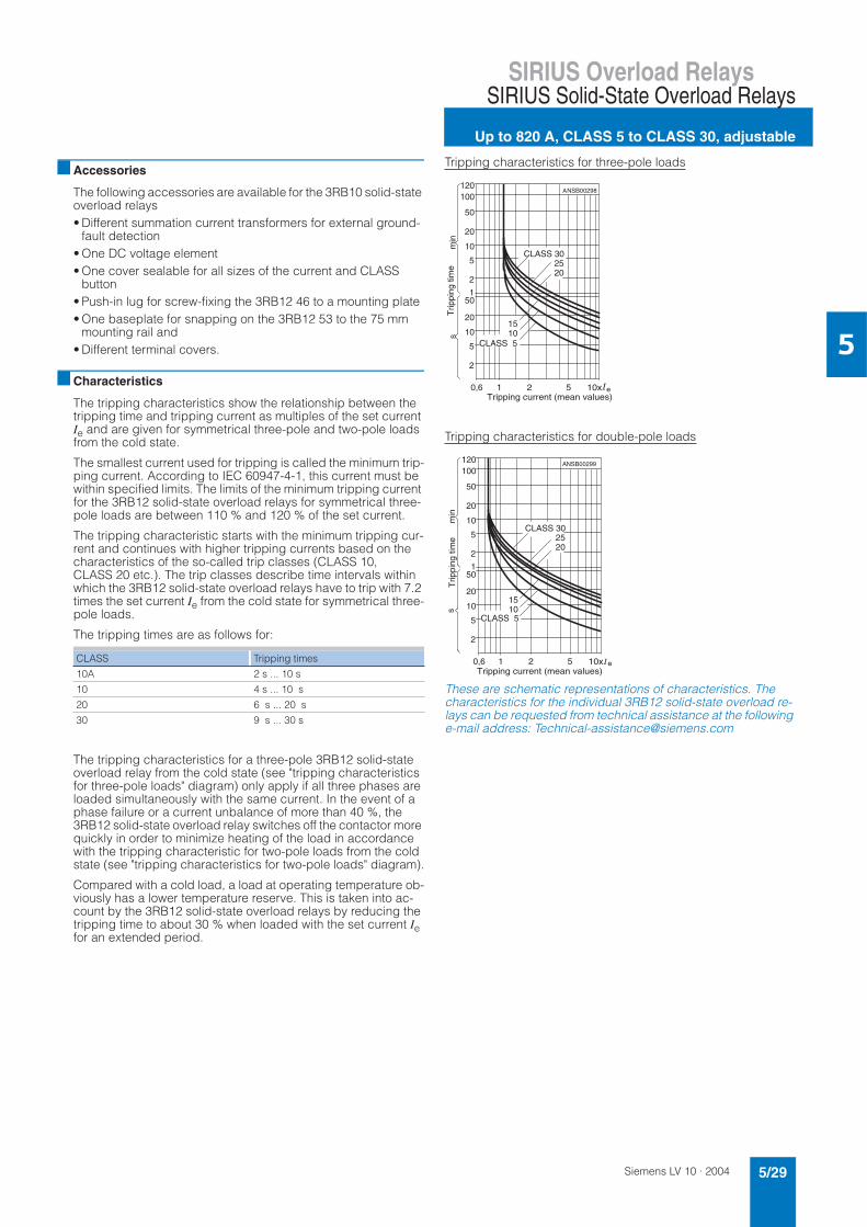
Siemens LV 10 · 2004 5/29
SIRIUS Overload RelaysSIRIUS Solid-State Overload Relays
Up to 820 A, CLASS 5 to CLASS 30, adjustable
5
Accessories
The following accessories are available for the 3RB10 solid-state overload relays• Different summation current transformers for external ground-
fault detection• One DC voltage element• One cover sealable for all sizes of the current and CLASS
button• Push-in lug for screw-fixing the 3RB12 46 to a mounting plate• One baseplate for snapping on the 3RB12 53 to the 75 mm
mounting rail and• Different terminal covers.
Characteristics
The tripping characteristics show the relationship between the tripping time and tripping current as multiples of the set current Ie and are given for symmetrical three-pole and two-pole loads from the cold state.
The smallest current used for tripping is called the minimum trip-ping current. According to IEC 60947-4-1, this current must be within specified limits. The limits of the minimum tripping current for the 3RB12 solid-state overload relays for symmetrical three-pole loads are between 110 % and 120 % of the set current.
The tripping characteristic starts with the minimum tripping cur-rent and continues with higher tripping currents based on the characteristics of the so-called trip classes (CLASS 10, CLASS 20 etc.). The trip classes describe time intervals within which the 3RB12 solid-state overload relays have to trip with 7.2 times the set current Ie from the cold state for symmetrical three-pole loads.
The tripping times are as follows for:
The tripping characteristics for a three-pole 3RB12 solid-state overload relay from the cold state (see "tripping characteristics for three-pole loads" diagram) only apply if all three phases are loaded simultaneously with the same current. In the event of a phase failure or a current unbalance of more than 40 %, the 3RB12 solid-state overload relay switches off the contactor more quickly in order to minimize heating of the load in accordance with the tripping characteristic for two-pole loads from the cold state (see "tripping characteristics for two-pole loads" diagram).
Compared with a cold load, a load at operating temperature ob-viously has a lower temperature reserve. This is taken into ac-count by the 3RB12 solid-state overload relays by reducing the tripping time to about 30 % when loaded with the set current Iefor an extended period.
Tripping characteristics for three-pole loads
Tripping characteristics for double-pole loads
These are schematic representations of characteristics. The characteristics for the individual 3RB12 solid-state overload re-lays can be requested from technical assistance at the following e-mail address: [email protected]
CLASS Tripping times
10A 2 s ... 10 s
10 4 s ... 10 s
20 6 s ... 20 s
30 9 s ... 30 s
120100
50
20
10
5
2
150
20
10
5
2
1 2 5 10xe
min
s
NSB00298
0,6
CLASS 30 25 20
15 10
CLASS 5
A
Trip
ping
tim
e
Tripping current (mean values)
120100
50
20
10
5
2
150
20
10
5
2
1 2 5 10xe
s
NSB00299
0,6
CLASS 30 25 20
1510
CLASS 5
A
Trip
ping
tim
e
Tripping current (mean values)
min
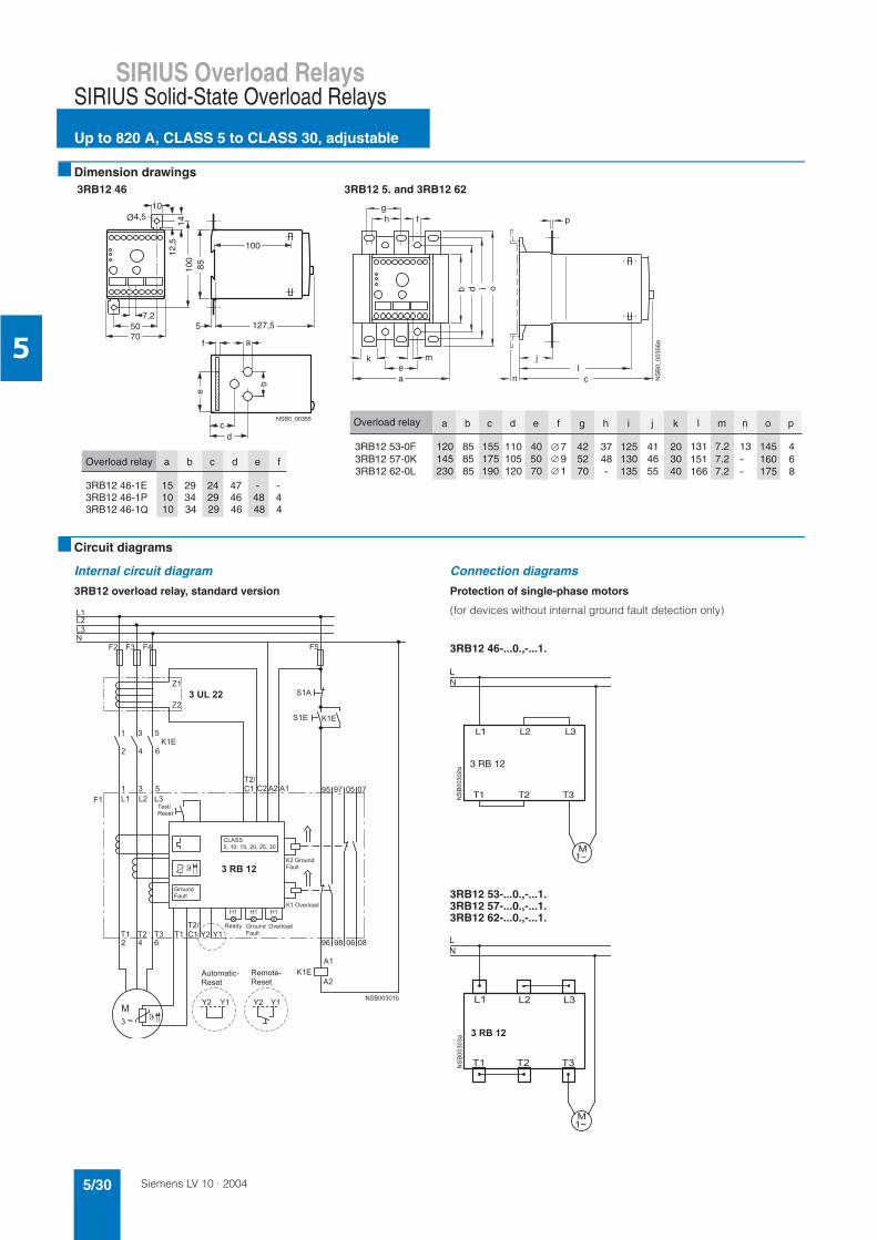
Siemens LV 10 · 20045/30
SIRIUS Overload Relays
Up to 820 A, CLASS 5 to CLASS 30, adjustable
SIRIUS Solid-State Overload Relays
5
Dimension drawings
Circuit diagrams
Internal circuit diagram
3RB12 overload relay, standard version
Connection diagrams
Protection of single-phase motors
(for devices without internal ground fault detection only)
3RB12 46-...0.,-...1.
3RB12 53-...0.,-...1.3RB12 57-...0.,-...1.3RB12 62-...0.,-...1.
3RB12 46 3RB12 5. and 3RB12 62
NSB0_00355
7,25070
100
4,5Ø
85
100
127,55
e
b
af
cd
10
12,5
14
Overload relay a b c d e f
3RB12 46-1E 15 29 24 47 - -3RB12 46-1P 10 34 29 46 48 43RB12 46-1Q 10 34 29 46 48 4
idb
gh f
ae
k m
cl
j
n
o
NS
B0_
0035
6a
p
3RB12 53-0F3RB12 57-0K3RB12 62-0L 230
145120
858585
190175155
120105110
705040
705242
-4837
135130125
554641
403020
166151131
7.27.27.2
--13
175160145
864
Overload relay a b c d e f g h i j k l m n o p
791
!"#$#
"##!"#$#
%&
'( ') ( )(* * * *
*+
"#,
-.#
%-.#
%
' '/ /*+
*#$+"#$#
(
%&
0
0
& %&
M1~
NS
B00
302a
L1 L2 L3
T1 T2 T3
LN
3 RB 12
* * *
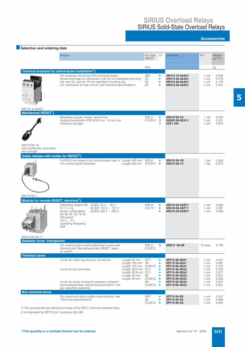
Siemens LV 10 · 2004 5/31
SIRIUS Overload RelaysSIRIUS Solid-State Overload Relays
Accessories
5
Selection and ordering data
1) The accessories are identical to those of the 3RU11 thermal overload relay.
2) As standard for 3RT10 54-1 contactor (55 kW).
Version For type 3RB10
DT Order No. PS* Weight per PU
Size kgTerminal brackets for stand-alone installation1)
3RU19 .6-3AA01
For separate mounting of the overload relays; Screw and snap-on connection onto 35 mm standard mounting rail, size S3, also for 75 mm standard mounting rail. For connection of main circuit, see technical specifications.
S00 3RU19 16-3AA01 1 unit 0.059S0 3RU19 26-3AA01 1 unit 0.078S2 3RU19 36-3AA01 1 unit 0.176S3 3RU19 46-3AA01 1 unit 0.281
Mechanical RESET1)
3RU19 00-1A with pushbutton and exten-sion plunger
Resetting plunger, holder, and former S00 to S10/S12
3RU19 00-1A 1 set 0.038Suitable pushbutton IP65 Ø 22 mm, 12 mm hub B 3SB30 00-0EA11 1 unit 0.021Extension plunger A 3SX1 335 1 unit 0.004
Cable release with holder for RESET1)
3RU19 00-1.
For Ø 6.5 mm holes in the control panel; max. 8 mm control panel thickness
Length 400 mm S00 to S10/S12
3RU19 00-1B 1 set 0.063Length 600 mm 3RU19 00-1C 1 set 0.073
Module for remote RESET, electrical1)
3RU19 00-2A.71
Operating range 0.85 to 1.1 x Us,power consumption AC 80 VA, DC 70 W, ON period 0.2 s ... 4 s, operating frequency 60/h
AC/DC 24 V ... 30 V S00 to S10/12
3RU19 00-2AB71 1 unit 0.066AC/DC 110 V ... 127 V 3RU19 00-2AF71 1 unit 0.067AC/DC 220 V ... 250 V 3RU19 00-2AM71 1 unit 0.066
Sealable cover, transparentFor covering the current adjustment screw and blocking the "Manual/automatic RESET" selec-tor switch
S00 to S10/S12
B 3RB19 00-3B 10 units 0.100
Terminal coverCover for cable lug and bus connection Length 55 mm S31) 3RT19 46-4EA1 1 unit 0.037
Length 100 mm S6 3RT19 56-4EA1 1 unit 0.067Length 120 mm S10/S12 3RT19 66-4EA1 1 unit 0.123
Cover for box terminals Length 20.6 mm S21) 3RT19 36-4EA2 1 unit 0.020Length 20.8 mm S31) 3RT19 46-4EA2 1 unit 0.017Length 25 mm S6 3RT19 56-4EA2 1 unit 0.021Length 30 mm S10/S12 3RT19 66-4EA2 1 unit 0.036
Cover for screw connector between contactor and overload relay, without box terminals (1 unit per assembly required)
S6 3RT19 56-4EA3 1 unit 0.021S10/S12 3RT19 66-4EA3 1 unit 0.061
Box terminal blockFor round and ribbon cable cross-sections, see "Technical specifications"
S62) 3RT19 55-4G 1 unit 0.237S6 3RT19 56-4G 1 unit 0.266S10/S12 3RT19 66-4G 1 unit 0.664
* This quantity or a multiple thereof can be ordered.
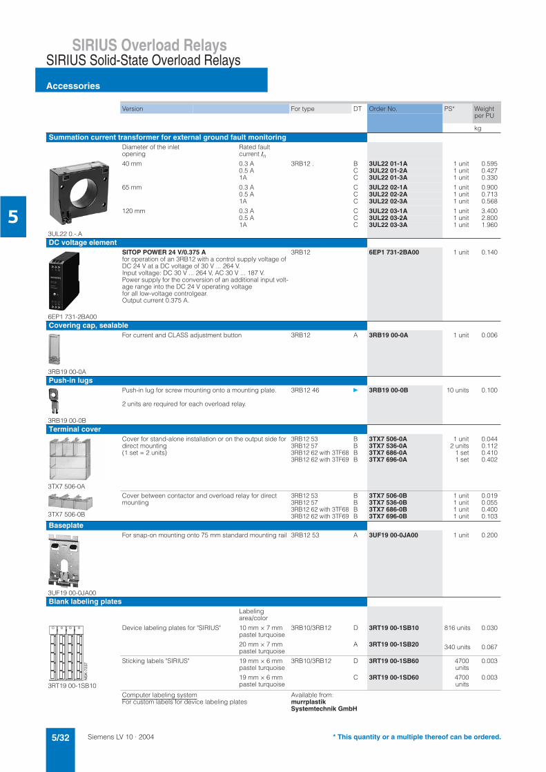
Siemens LV 10 · 20045/32
SIRIUS Overload Relays
Accessories
SIRIUS Solid-State Overload Relays
5
Version For type DT Order No. PS* Weight per PU
kgSummation current transformer for external ground fault monitoring
Diameter of the inlet opening
Rated fault current In
3UL22 0.-.A
40 mm 0.3 A 3RB12 . B 3UL22 01-1A 1 unit 0.5950.5 A C 3UL22 01-2A 1 unit 0.4271A C 3UL22 01-3A 1 unit 0.330
65 mm 0.3 A C 3UL22 02-1A 1 unit 0.9000.5 A C 3UL22 02-2A 1 unit 0.7131A C 3UL22 02-3A 1 unit 0.568
120 mm 0.3 A C 3UL22 03-1A 1 unit 3.4000.5 A C 3UL22 03-2A 1 unit 2.8001A C 3UL22 03-3A 1 unit 1.960
DC voltage element
6EP1 731-2BA00
SITOP POWER 24 V/0.375 Afor operation of an 3RB12 with a control supply voltage of DC 24 V at a DC voltage of 30 V ... 264 V. Input voltage: DC 30 V ... 264 V, AC 30 V ... 187 V. Power supply for the conversion of an additional input volt-age range into the DC 24 V operating voltage for all low-voltage controlgear. Output current 0.375 A.
3RB12 6EP1 731-2BA00 1 unit 0.140
Covering cap, sealable
3RB19 00-0A
For current and CLASS adjustment button 3RB12 A 3RB19 00-0A 1 unit 0.006
Push-in lugs
3RB19 00-0B
Push-in lug for screw mounting onto a mounting plate.
2 units are required for each overload relay.
3RB12 46 3RB19 00-0B 10 units 0.100
Terminal cover
3TX7 506-0A
Cover for stand-alone installation or on the output side for direct mounting (1 set = 2 units)
3RB12 533RB12 573RB12 62 with 3TF683RB12 62 with 3TF69
BBBB
3TX7 506-0A3TX7 536-0A3TX7 686-0A3TX7 696-0A
1 unit2 units
1 set1 set
0.0440.1120.4100.402
3TX7 506-0B
Cover between contactor and overload relay for direct mounting
3RB12 533RB12 573RB12 62 with 3TF683RB12 62 with 3TF69
BBBB
3TX7 506-0B3TX7 536-0B3TX7 686-0B3TX7 696-0B
1 unit1 unit1 unit1 unit
0.0190.0550.4000.103
Baseplate
3UF19 00-0JA00
For snap-on mounting onto 75 mm standard mounting rail 3RB12 53 A 3UF19 00-0JA00 1 unit 0.200
Blank labeling plates Labelingarea/color
3RT19 00-1SB10
Device labeling plates for "SIRIUS" 10 mm × 7 mm pastel turquoise
20 mm × 7 mm pastel turquoise
3RB10/3RB12 D
A
3RT19 00-1SB10
3RT19 00-1SB20
816 units
340 units
0.030
0.067
Sticking labels "SIRIUS" 19 mm × 6 mm pastel turquoise
19 mm × 6 mm pastel turquoise
3RB10/3RB12 D
C
3RT19 00-1SB60
3RT19 00-1SD60
4700units
4700units
0.003
0.003
Computer labeling systemFor custom labels for device labeling plates
Available from:murrplastikSystemtechnik GmbH
NS
K-7
237
* This quantity or a multiple thereof can be ordered.
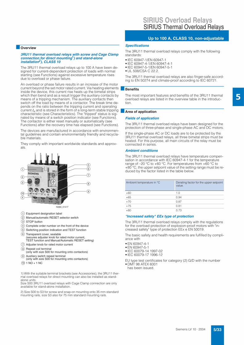
Siemens LV 10 · 2004 5/33
SIRIUS Overload RelaysSIRIUS Thermal Overload Relays
Up to 100 A, CLASS 10, non-adjustable
5
Overview
3RU11 thermal overload relays with screw and Cage Clamp connection for direct mounting1) and stand-alone installation2), CLASS 10
The 3RU11 thermal overload relays up to 100 A have been de-signed for current-dependent protection of loads with normal starting (see Functions) against excessive temperature rises due to overload or phase failure.
An overload or phase failure results in an increase of the motor current beyond the set motor rated current. Via heating elements inside the device, this current rise heats up the bimetal strips which then bend and as a result trigger the auxiliary contacts by means of a tripping mechanism. The auxiliary contacts then switch off the load by means of a contactor. The break time de-pends on the ratio between the tripping current and operating current Ie and is stored in the form of a long-term stable tripping characteristic (see Characteristics). The "tripped" status is sig-naled by means of a switch position indicator (see Functions). The contactor is either reset manually or automatically (see Functions) after the recovery time has elapsed (see Functions).
The devices are manufactured in accordance with environmen-tal guidelines and contain environmentally friendly and recycla-ble materials.
They comply with important worldwide standards and approv-als.
1) With the suitable terminal brackets (see Accessories), the 3RU11 ther-mal overload relays for direct mounting can also be installed as stand-alone units. Size S00 3RU11 overload relays with Cage Clamp connection are only available for stand-alone installation.
2) Size S00 to S3 for screw and snap-on mounting onto 35 mm standard mounting rails, size S3 also for 75 mm standard mounting rails.
Specifications
The 3RU11 thermal overload relays comply with the following standards:• IEC 60947-1/EN 60947-1• IEC 60947-4-1/EN 60947-4-1• IEC 60947-5-1/EN 60947-5-1• UL 508/CSA C 22.2.
The 3RU11 thermal overload relays are also finger-safe accord-ing to EN 50274 and climate-proof according to IEC 60721.
Benefits
The most important features and benefits of the 3RU11 thermal overload relays are listed in the overview table in the introduc-tion.
Area of application
Fields of application
The 3RU11 thermal overload relays have been designed for the protection of three-phase and single-phase AC and DC motors.
If the single-phase AC or DC loads are to be protected by the 3RU11 thermal overload relays, all three bimetal strips must be heated. For this purpose, all main circuits of the relay must be connected in series.
Ambient conditions
The 3RU11 thermal overload relays have temperature compen-sation in accordance with IEC 60947-4-1 for the temperature range of –20 °C to +60 °C. For temperatures from +60 °C to +80 °C, the upper setpoint value of the setting range must be re-duced by the factor listed in the table below.
"Increased safety" EEx type of protection
The 3RU11 thermal overload relays comply with the regulations for the overload protection of explosion-proof motors with "in-creased safety" type of protection EEx e EN 50019.
The basic safety and health requirements are fulfilled by compli-ance with• EN 60947-4-1• EN 60947-5-1• IEC 60079-14 1997-02• IEC 60079-17 1996-12
EU type test certificates for category (2) G/D with the number• DMT 98 ATEX 6001
has been issued.
'
&
'
(
F")/.&%& )2)+&+C"+3".)- &+& ()*-"./+&&%&".&*&00*&%&?)&()*)2/ )))%))%--0")
- /&?&! &++&@ &"& %E" &,0&%."&!--0")%C"+3'".)- &)20'%E" &,0&%."&
&/&)+&.)+@+1()* )4&0.")2 0'"#)+)1 ()*&/&&.)+@+1()* )4&0.")2 05
&
'
(
Ambient temperature in °C Derating factor for the upper setpoint value.
+60 1.0
+65 0.94
+70 0.87
+75 0.81
+80 0.73
Siemens LV 10 · 20045/34
SIRIUS Overload Relays
Up to 100 A, CLASS 10, non-adjustable
SIRIUS Thermal Overload Relays
5
Design
Mounting options
The 3RU11 thermal overload relays can be mounted directly onto the 3RT1 contactors (exception: size S00 with Cage Clamp connection can only be installed as a stand-alone unit). The de-vices can also be installed as stand-alone units with the corre-sponding terminal brackets.
For more information on the mounting options, please consult the technical specifications as well as the selection and ordering data.
Connections
All sizes of the 3RU11 thermal overload relays with screw con-nection can be connected to the auxiliary and main conducting paths. Rails can be connected to the main conducting path ter-minals of size S3 overload relays if the box terminals are re-moved.
As an alternative, the units are also available with Cage Clamp connection. The auxiliary conducting path terminals of these units, and for size S00 the main conducting path terminals as well, are fitted with Cage Clamp connections.
For more information on the different connection options, please consult the technical specifications as well as the selection and ordering data.
Overload relays in star-delta assemblies
When overload relays are used in combination with star-delta as-semblies it must be noted that only 0.58 times the motor current flows through the line contactor. An overload relay mounted onto the line contactor must be set to 0.58 times the motor current.
An assignment of the 3RU11 thermal overload relays to the line contactors of our 3RA star-delta assemblies can be found under "Controlgear: Contactors and Contactor Assemblies".
Operation with frequency converter
The 3RU11 thermal overload relays are suitable for operation with frequency converters. Depending on the frequency of the converter, a higher current than the motor current must be used in some cases due to eddy currents and skin effects.
Functions
Control circuit
The 3RU11 thermal overload relays do not require an additional supply voltage for operation.
Short-circuit protection
Fuses or circuit-breakers must be used for short-circuit protec-tion. Assignments for the corresponding short-circuit protection devices to the 3RU11 thermal overload relays with/without con-tactor can be found in the technical specifications or selection and ordering data.
Trip classes
The 3RU11 thermal overload relays are available for normal starting conditions with trip class CLASS 10. Detailed informa-tion about the trip classes can be found under "Characteristics".
Phase failure protection
The 3RU11 thermal overload relays are fitted with phase failure sensitivity (see "Characteristics") in order to minimize tempera-ture rises of the load in the case of a phase failure during single-phase operation.
Setting
The 3RU11 thermal overload relay is set to the motor rated cur-rent by means of a rotary knob. The scale of the rotary knob is calibrated in ampere.
Manual and automatic reset
Automatic and manual reset is selected by pressing and turning the blue button (RESET button). If the button is set to manual re-set, the overload relay can be reset directly by pressing the RESET button. Remote resetting is possible in combination with mechanical and electrical RESET modules from the accessories range (see Accessories). If the blue button is set to automatic RESET, the relay is reset automatically.
The relay can only be reset after the recovery time has elapsed.
Recovery time
After tripping due to overload, the 3RU11 thermal overload re-lays require some time until the bimetal strips have cooled down. The device can only be reset after the bimetal strips have cooled down. This time (recovery time) depends on the tripping charac-teristics and strength of the tripping current.
The recovery time allows the load to cool down after tripping due to overload.
TEST function
The TEST slide can be used to check whether the operational 3RU11 thermal overload relay is working properly. Actuating the slide simulates tripping of the relay. During this simulation the NC contact (95-96) is opened and the NO contact (97-98) is closed. This tests whether the auxiliary circuit has been cor-rectly connected to the overload relay. If the 3RU11 thermal overload relay has been set to automatic RESET, the overload re-lay is automatically reset when the TEST slide is released. The relay must be reset with the RESET button if it has been set to manual RESET.
STOP function
If the STOP button is pressed, the NC contact is opened. This switches off the contactor downstream and thus the load. The load is switched on again when the STOP button is released.
Display of the operating status
The status of the 3RU11 thermal overload relay is displayed by means of the position of the marking on the TEST function/switch position indicator slide. After tripping due to overload or phase failure, the marking on the slide is to left on the "O" mark, other-wise it is on the "I" mark.
Auxiliary contacts
The 3RU11 thermal overload relay is fitted with an NO contact for the "tripped" signal, and an NC contact for switching off the con-tactor.
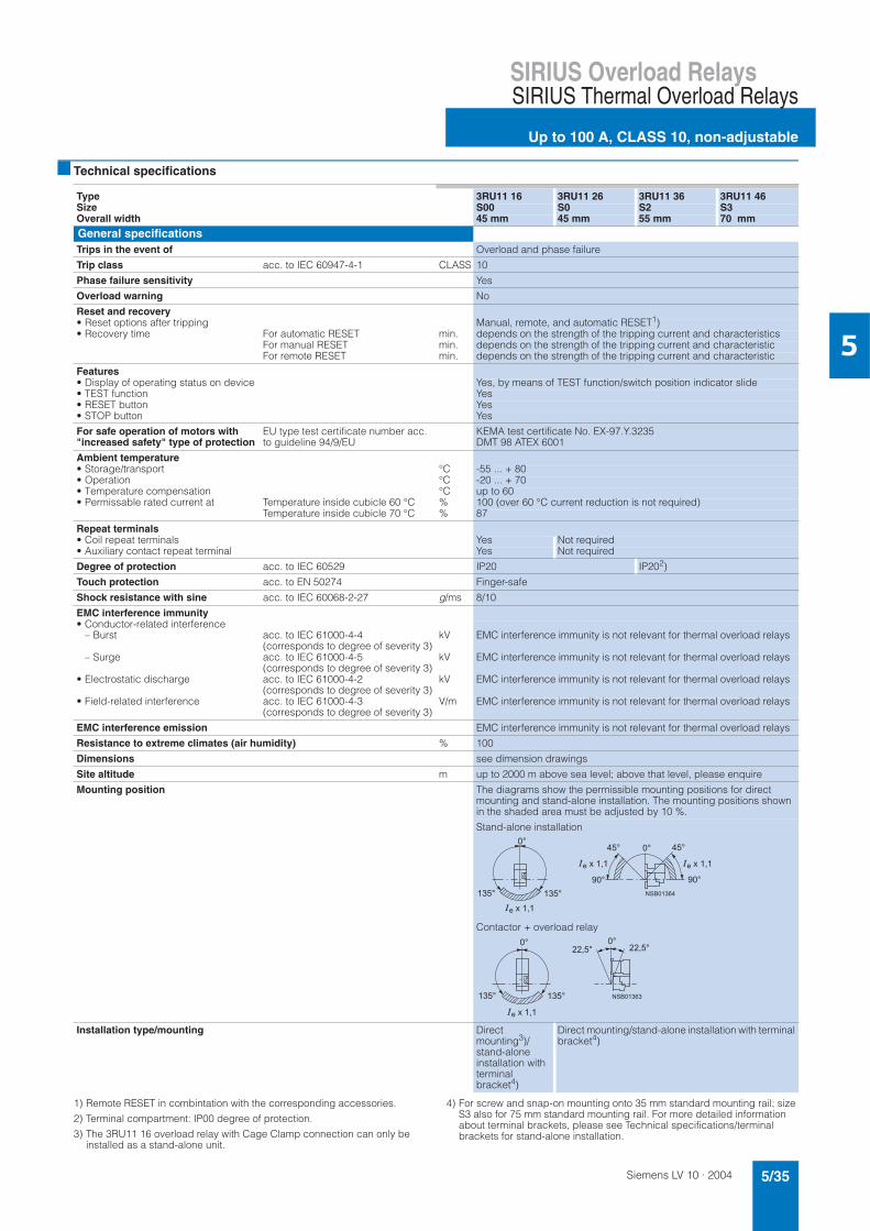
Siemens LV 10 · 2004 5/35
SIRIUS Overload RelaysSIRIUS Thermal Overload Relays
Up to 100 A, CLASS 10, non-adjustable
5
Technical specifications
1) Remote RESET in combintation with the corresponding accessories.
2) Terminal compartment: IP00 degree of protection.
3) The 3RU11 16 overload relay with Cage Clamp connection can only be installed as a stand-alone unit.
4) For screw and snap-on mounting onto 35 mm standard mounting rail; size S3 also for 75 mm standard mounting rail. For more detailed information about terminal brackets, please see Technical specifications/terminal brackets for stand-alone installation.
Type 3RU11 16 3RU11 26 3RU11 36 3RU11 46Size S00 S0 S2 S3Overall width 45 mm 45 mm 55 mm 70 mm
General specificationsTrips in the event of Overload and phase failure
Trip class acc. to IEC 60947-4-1 CLASS 10
Phase failure sensitivity Yes
Overload warning No
Reset and recovery• Reset options after tripping Manual, remote, and automatic RESET1)• Recovery time For automatic RESET min. depends on the strength of the tripping current and characteristics
For manual RESET min. depends on the strength of the tripping current and characteristicFor remote RESET min. depends on the strength of the tripping current and characteristic
Features• Display of operating status on device Yes, by means of TEST function/switch position indicator slide• TEST function Yes• RESET button Yes• STOP button Yes
For safe operation of motors with "increased safety" type of protection
EU type test certificate number acc. to guideline 94/9/EU
KEMA test certificate No. EX-97.Y.3235DMT 98 ATEX 6001
Ambient temperature• Storage/transport °C -55 ... + 80• Operation °C -20 ... + 70• Temperature compensation °C up to 60• Permissable rated current at Temperature inside cubicle 60 °C % 100 (over 60 °C current reduction is not required)
Temperature inside cubicle 70 °C % 87
Repeat terminals• Coil repeat terminals Yes Not required• Auxiliary contact repeat terminal Yes Not required
Degree of protection acc. to IEC 60529 IP20 IP202)
Touch protection acc. to EN 50274 Finger-safe
Shock resistance with sine acc. to IEC 60068-2-27 g/ms 8/10
EMC interference immunity• Conductor-related interference
– Burst acc. to IEC 61000-4-4 (corresponds to degree of severity 3)
kV EMC interference immunity is not relevant for thermal overload relays
– Surge acc. to IEC 61000-4-5 (corresponds to degree of severity 3)
kV EMC interference immunity is not relevant for thermal overload relays
• Electrostatic discharge acc. to IEC 61000-4-2 (corresponds to degree of severity 3)
kV EMC interference immunity is not relevant for thermal overload relays
• Field-related interference acc. to IEC 61000-4-3 (corresponds to degree of severity 3)
V/m EMC interference immunity is not relevant for thermal overload relays
EMC interference emission EMC interference immunity is not relevant for thermal overload relays
Resistance to extreme climates (air humidity) % 100
Dimensions see dimension drawings
Site altitude m up to 2000 m above sea level; above that level, please enquire
Mounting position The diagrams show the permissible mounting positions for direct mounting and stand-alone installation. The mounting positions shown in the shaded area must be adjusted by 10 %.
Stand-alone installation
Contactor + overload relay
Installation type/mounting Direct mounting3)/stand-aloneinstallation with terminal bracket4)
Direct mounting/stand-alone installation with terminal bracket4)
Siemens LV 10 · 20045/36
SIRIUS Overload Relays
Up to 100 A, CLASS 10, non-adjustable
SIRIUS Thermal Overload Relays
5
1) For conductor cross-sections for Cage Clamp connections, see connec-tion of the auxiliary circuit.
2) The box terminal is removable. Rail and cable lug connections are possi-ble if the box terminal is removed.
Type 3RU11 16 3RU11 26 3RU11 36 3RU11 46Size S00 S0 S2 S3Overall width 45 mm 45 mm 55 mm 70 mm
Main circuitRated insulation voltage Ui (pollution degree 3) V 690 1000
Rated impulse withstand voltage Uimp kV 6 8
Rated operating voltage Ue V 690 1000
Type of current• DC Yes• AC Yes, frequency range up to 400 Hz
Current setting A 0.11-0.16 ... 9-12 1.8-2.5 ... 20-25 5.5-8 ... 40-50 18-25 ... 80-100
Power loss per unit (max.) W 3.9 ... 6.6 3.9 ... 6 6 ... 9 10 ... 16.5
Short-circuit protection with fuse without contactor see selection and ordering datawith fuse and contactor see Technical specifications (short-circuit protection with fuses/circuit-
breakers for motor feeders)
Safe isolation between main and auxiliary conducting path
acc. to IEC 60947-1 V 500 690
Connection for main circuitType of connection Screw connec-
tion/Cage Clamp connection1)
Screw connection Screw connec-tion with box ter-minal
Screw connec-tion with box terminal/rail connection2)
Screw connection• Terminal screw Pozidrive size 2 4 mm Allen
screw• Tightening torque Nm 0.8 ... 1.2 2 ... 2.5 3 ... 4.5 4 ... 6• Conductor cross-section
(min./max.), 1 or 2 conductorsSolid mm2 2 x (0.5 ... 1.5)
2 x (0.75 ... 2.5)max. 2 x (1 ... 4)
2 x (1 ... 2.5)2 x (2.5 ... 6)max. 2 x (2.5 ... 10)
2 x (0.75 ... 16) 2 x (2.5 ... 16)
Finely stranded without end sleeve mm2 –Finely stranded with end sleeve mm2 2 x (0.5 ... 1.5)
2 x (0.75 ... 2.5)2 x (1 ... 2.5)2 x (2.5 ... 6)
2 x (0.75 ... 16)1x ( 0.75 ... 25)
2 x (2.5 ... 35)1 x (2.5 ... 50)
Stranded mm2 2 x (0.5 ... 1.5)2 x (0.75 ... 2.5)max. 2 x (1 ... 4)
2 x (1 ... 2.5)2 x (2.5 ... 6)max. 2 x (2.5 ... 10)
2 x (0.75 ... 25)1 x (0.75 ... 35)
2 x (10 ... 50)1 x (10 ... 70)
AWG conductor connections, solid or stranded
AWG 2 x (18 ... 14) 2 x (14 ... 10) 2 x (18 ... 3)1 x (18 ... 1)
2 x (10 ... 1/0)1 x (10 ... 2/0)
Ribbon cables(number x width x circumference)
mm – – 2 x (6 x 9 x 0.8) 2 x (6 x 9 x 0.8)
Rail connection• Terminal screw – M 6 x 20• Tightening torque Nm – 4 ... 6• Conductor cross-section
(min./max.)Finely stranded with cable lug mm2 – 2 x 70Stranded with cable lug mm2 – 3 x 70AWG conductor connections, solid or stranded, with cable lug
AWG – 2/0
With connecting bar (max. width) mm – 12
Straight-through transformer connection• Diameter of opening mm –• Conductor cross-section (max.) NYY mm2 –
H07RN-F mm2 –Auxiliary circuitAuxiliary contacts: Number x (version) 1 x (1 NO + 1 NC)
Assignment of auxiliary contacts 1 NO for the "tripped due to overload" signal; 1 NC for switching off the contactor
Rated insulation voltage Ui (pollution degree 3) V 690
Rated impulse withstand voltage Uimp kV 6
Siemens LV 10 · 2004 5/37
SIRIUS Overload RelaysSIRIUS Thermal Overload Relays
Up to 100 A, CLASS 10, non-adjustable
5
1) on request
2) Up to Ik ≤ 0.5 kA; ≤ 260 V.
Terminal brackets for stand-alone installation
Type 3RU11 16 3RU11 26 3RU11 36 3RU11 46Size S00 S0 S2 S3Overall width 45 mm 45 mm 55 mm 70 mmAuxiliary circuitContact rating of the auxiliary contacts• NC at AC,
AC-14/AC-15 Rated operating current Ie for Ue:– 24 V A 4– 120 V A 4– 125 V A 4– 230 V A 3– 400 V A 2– 600 V A 0.6– 690 V A 0.5
• NO at AC, AC-14/AC-15
Rated operating current Ie at Ue:– 24 V A 3– 120 V A 3– 125 V A 3– 230 V A 2– 400 V A 1– 600 V A 0.6– 690 V A 0.5
• NC, NO at DC, DC-13
Rated operating current Ie at Ue:– 24 V A 1– 60 V A 1)– 110 V A 0.22– 125 V A 0.22– 220 V A 0.11
• Conventional thermal current Ith A 6
• Contact reliability (suitable for PLC control; 17 V, 5 mA)
Yes
Short-circuit protection • With fuse Operational class gL/gG A 6
Quick A 10• With miniature circuit-breaker (C-characteristic) A 62)
Safe isolation between auxiliary circuits
acc. to IEC 60947-1 V 415
Connection for auxiliary circuitType of connection Screw connection or Cage Clamp connection
Connection features Screw connection Cage Clamp connection• Terminal screw Pozidrive size 2 –• Tightening torque Nm 0.8 ... 1.2 –• Conductor cross-sections
(min./max.), 1 or 2 conductorsSolid mm2 2 x (0.5 ... 1.5)
2 x (0.75 ... 2.5)2 x (0.25 ... 2.5)
Finely stranded without end sleeve mm2 – 2 x (0.25 ... 2.5)Finely stranded with end sleeve mm2 2 x (0.5 ... 1.5)
2 x (0.75 ... 2.5)2 x (0.25 ... 1.5)
Stranded mm2 2 x (0.5 ... 1.5)2 x (0.75 ... 2.5)
–
AWG conductor connections, solid or stranded
AWG 2 x (18 ... 14) 2 x (24 ... 14)
CSA, UL, and UR ratingsAuxiliary circuit Switching capacity B600, R300
Type 3RU19 16-3AA01 3RU19 26-3AA01 3RU19 36-3AA01 3RU19 46-3AA01
for overload relay 3RU11 16 3RU11 26 3RU11 36 3RU11 46
Mounting type For screw and snap-on mounting onto 35 mm standard mounting rail; Size S3, also for 75 mm standard mounting rail.
Connection for main circuitType of connection Screw connection Screw connection with box terminal
Screw connection• Terminal screw Pozidrive size 2 4 mm Allen screw
• Conductor cross-section(min./max.), 1 or 2 conductors
Solid mm2 1 x (0.5 ... 2.5) max. 1 x (... 4)
1 x (1 ... 6) max. 1 x (... 10)
2 x (0.75 ... 16) 2 x (2.5 ... 16)
Finely stranded without end sleeve mm2 –Finely stranded with end sleeve mm2 1 x (0.5 ... 2.5) 1 x (1 ... 6) 2 x (0.75 ... 16)
1x ( 0.75 ... 25)2 x (2.5 ... 35)1 x (2.5 ... 50)
Stranded mm2 1 x (0.5 ... 2.5) max. 1 x (... 4)
1 x (1 ... 6) max. 1 x (... 10)
2 x (0.75 ... 25)1 x (0.75 ... 35)
2 x (10 ... 50)1 x (10 ... 70)
AWG conductor connections, solid or stranded
AWG 1 x (18 ... 14) 1 x (14 ... 10) 2 x (18 ... 3)1 x (18 ... 1)
2 x (10 ... 1/0)2 x (10 ... 2/0)
Ribbon cables(number x width x circumference)
mm – – 2 x (6 x 9 x 0.8) 2 x (6 x 9 x 0.8)
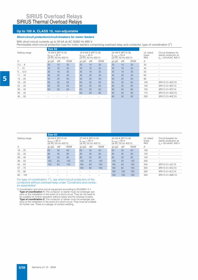
Siemens LV 10 · 20045/38
SIRIUS Overload Relays
Up to 100 A, CLASS 10, non-adjustable
SIRIUS Thermal Overload Relays
5
Short-circuit protection/circuit-breakers for motor feeders
With short-circuit currents up to 50 kA at AC 50/60 Hz 690 V.Permissible short-circuit protection fuse for motor starters comprising overload relay and contactor, type of coordination 21)
For type of coordination 11), see short-circuit protection of the contactors without overload relay under "Contactors and contac-tor assemblies".1) Coordination and short-circuit equipment according to EN 60947-4-1:
Type of coordination 1: The contactor or starter must not endanger per-sons or the installation in the event of a short-circuit. They do not need to be suitable for further operation without repair and the renewal of parts. Type of coordination 2: The contactor or starter must not endanger per-sons or the installation in the event of a short-circuit. They must be suitable for further use. There is a danger of contact welding.
Size S2Setting range 15 kW r 3RT10 34
Iemax = 32 A (at AC 50 Hz 400 V)
18.5 kW r 3RT10 35 Iemax = 40 A (at AC 50 Hz 400 V)
22 kW r 3RT10 36 Ie max = 50 A (at AC 50 Hz 400 V)
UL-listedfusesRK5
Circuit-breakers for starter protection atIq = 50 kA/AC 400 V
A gL/gG aM BS88 gL/gG aM BS88 gL/gG aM BS88 A
5.5 ... 8 25 10 25 25 10 25 25 10 25 30 –
7 ... 10 32 16 32 32 16 32 32 16 32 40 –
9 ... 12.5 35 16 35 35 16 35 35 16 35 50 –
11 ... 16 40 20 40 40 20 40 40 20 40 60 –
14 ... 20 50 25 50 50 25 50 50 25 50 80 –
18 ... 25 63 32 63 63 32 63 63 32 63 100 3RV13 31-4DC10
22 ... 32 63 35 63 63 35 63 80 35 80 125 3RV13 31-4EC10
28 ... 40 63 50 63 63 50 63 80 50 80 150 3RV13 31-4FC10
36 ... 45 – – – 63 50 80 80 50 80 175 3RV13 31-4GC10
40 ... 50 – – – – – – 80 50 80 200 3RV13 31-4HC10
Size S3Setting range 30 kW r 3RT10 44
Iemax = 65 A (at AC 50 Hz 400 V)
37 kW r 3RT10 45 Ie max = 80 A (at AC 50 Hz 400 V)
45 kW r 3RT10 46 Ie max = 95 A (at AC 50 Hz 400 V)
UL-listedfusesRK5
Circuit-breaker for starter protection atIq = 50 kA/AC 400 V
A gL/gG aM BS88 gL/gG aM BS88 gL/gG aM BS88 A
18 ... 25 63 32 63 63 32 63 63 32 63 100 –
22 ... 32 80 35 80 80 35 80 80 35 80 125 –
28 ... 40 80 50 80 80 50 80 80 50 80 150 –
36 ... 50 125 50 125 125 50 125 125 50 125 200 –
45 ... 63 125 63 125 160 63 160 160 63 160 250 3RV13 41-4JC10
57 ... 75 – – – 160 80 160 160 80 160 300 3RV13 41-4KC10
70 ... 90 – – – – – – 160 100 160 350 3RV13 41-4LC10
80 ... 100 – – – – – – 160 100 160 350 3RV13 41-4MC10
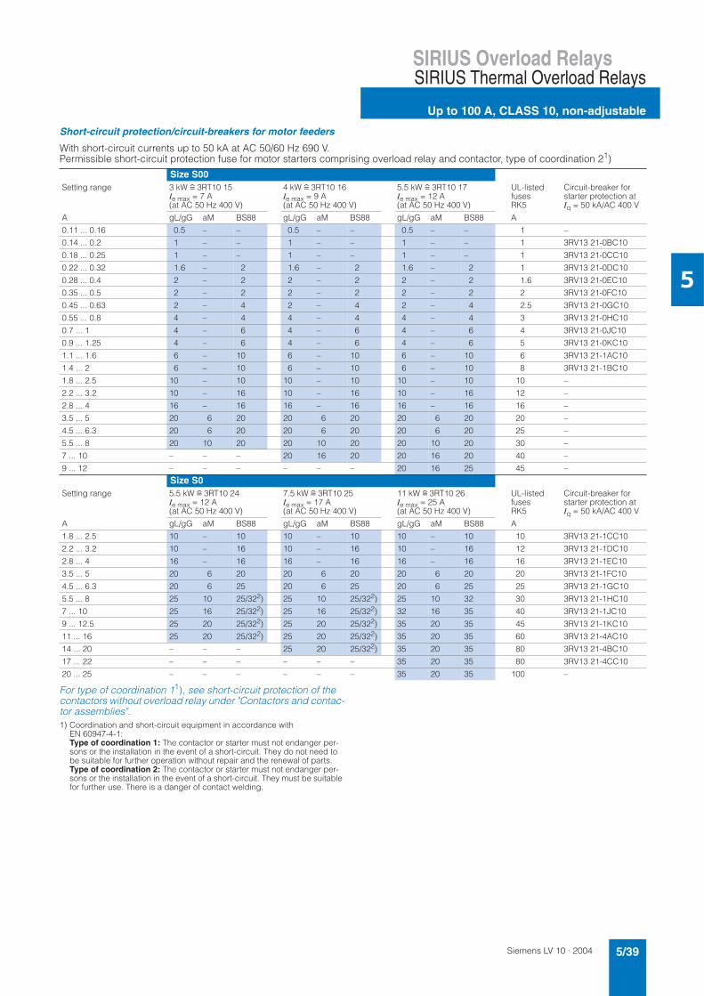
Siemens LV 10 · 2004 5/39
SIRIUS Overload RelaysSIRIUS Thermal Overload Relays
Up to 100 A, CLASS 10, non-adjustable
5
Short-circuit protection/circuit-breakers for motor feeders
With short-circuit currents up to 50 kA at AC 50/60 Hz 690 V.Permissible short-circuit protection fuse for motor starters comprising overload relay and contactor, type of coordination 21)
For type of coordination 11), see short-circuit protection of the contactors without overload relay under "Contactors and contac-tor assemblies".1) Coordination and short-circuit equipment in accordance with
EN 60947-4-1: Type of coordination 1: The contactor or starter must not endanger per-sons or the installation in the event of a short-circuit. They do not need to be suitable for further operation without repair and the renewal of parts. Type of coordination 2: The contactor or starter must not endanger per-sons or the installation in the event of a short-circuit. They must be suitable for further use. There is a danger of contact welding.
Size S00Setting range 3 kW r 3RT10 15
Ie max = 7 A (at AC 50 Hz 400 V)
4 kW r 3RT10 16 Ie max = 9 A (at AC 50 Hz 400 V)
5.5 kW r 3RT10 17 Ie max = 12 A (at AC 50 Hz 400 V)
UL-listedfusesRK5
Circuit-breaker for starter protection atIq = 50 kA/AC 400 V
A gL/gG aM BS88 gL/gG aM BS88 gL/gG aM BS88 A
0.11 ... 0.16 0.5 – – 0.5 – – 0.5 – – 1 –
0.14 ... 0.2 1 – – 1 – – 1 – – 1 3RV13 21-0BC10
0.18 ... 0.25 1 – – 1 – – 1 – – 1 3RV13 21-0CC10
0.22 ... 0.32 1.6 – 2 1.6 – 2 1.6 – 2 1 3RV13 21-0DC10
0.28 ... 0.4 2 – 2 2 – 2 2 – 2 1.6 3RV13 21-0EC10
0.35 ... 0.5 2 – 2 2 – 2 2 – 2 2 3RV13 21-0FC10
0.45 ... 0.63 2 – 4 2 – 4 2 – 4 2.5 3RV13 21-0GC10
0.55 ... 0.8 4 – 4 4 – 4 4 – 4 3 3RV13 21-0HC10
0.7 ... 1 4 – 6 4 – 6 4 – 6 4 3RV13 21-0JC10
0.9 ... 1.25 4 – 6 4 – 6 4 – 6 5 3RV13 21-0KC10
1.1 ... 1.6 6 – 10 6 – 10 6 – 10 6 3RV13 21-1AC10
1.4 ... 2 6 – 10 6 – 10 6 – 10 8 3RV13 21-1BC10
1.8 ... 2.5 10 – 10 10 – 10 10 – 10 10 –
2.2 ... 3.2 10 – 16 10 – 16 10 – 16 12 –
2.8 ... 4 16 – 16 16 – 16 16 – 16 16 –
3.5 ... 5 20 6 20 20 6 20 20 6 20 20 –
4.5 ... 6.3 20 6 20 20 6 20 20 6 20 25 –
5.5 ... 8 20 10 20 20 10 20 20 10 20 30 –
7 ... 10 – – – 20 16 20 20 16 20 40 –
9 ... 12 – – – – – – 20 16 25 45 –
Size S0Setting range 5.5 kW r 3RT10 24
Ie max = 12 A (at AC 50 Hz 400 V)
7.5 kW r 3RT10 25 Ie max = 17 A (at AC 50 Hz 400 V)
11 kW r 3RT10 26 Ie max = 25 A (at AC 50 Hz 400 V)
UL-listedfusesRK5
Circuit-breaker for starter protection atIq = 50 kA/AC 400 V
A gL/gG aM BS88 gL/gG aM BS88 gL/gG aM BS88 A
1.8 ... 2.5 10 – 10 10 – 10 10 – 10 10 3RV13 21-1CC10
2.2 ... 3.2 10 – 16 10 – 16 10 – 16 12 3RV13 21-1DC10
2.8 ... 4 16 – 16 16 – 16 16 – 16 16 3RV13 21-1EC10
3.5 ... 5 20 6 20 20 6 20 20 6 20 20 3RV13 21-1FC10
4.5 ... 6.3 20 6 25 20 6 25 20 6 25 25 3RV13 21-1GC10
5.5 ... 8 25 10 25/322) 25 10 25/322) 25 10 32 30 3RV13 21-1HC10
7 ... 10 25 16 25/322) 25 16 25/322) 32 16 35 40 3RV13 21-1JC10
9 ... 12.5 25 20 25/322) 25 20 25/322) 35 20 35 45 3RV13 21-1KC10
11 ... 16 25 20 25/322) 25 20 25/322) 35 20 35 60 3RV13 21-4AC10
14 ... 20 – – – 25 20 25/322) 35 20 35 80 3RV13 21-4BC10
17 ... 22 – – – – – – 35 20 35 80 3RV13 21-4CC10
20 ... 25 – – – – – – 35 20 35 100 –
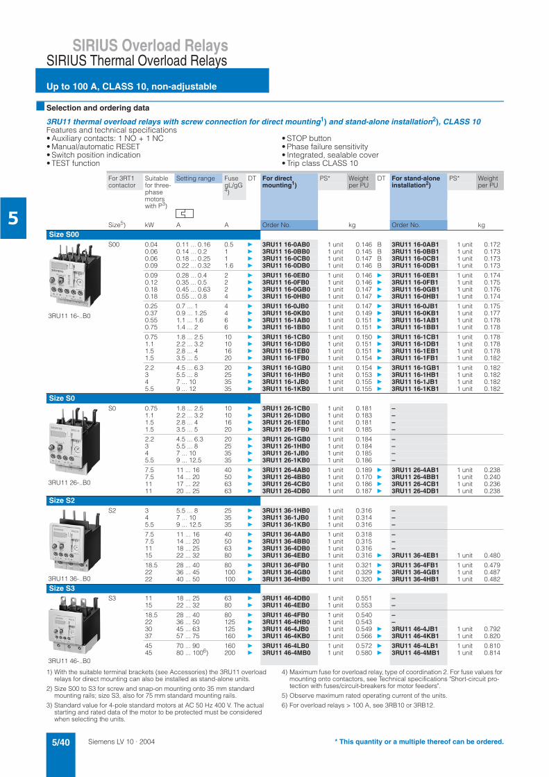
Siemens LV 10 · 20045/40
SIRIUS Overload Relays
Up to 100 A, CLASS 10, non-adjustable
SIRIUS Thermal Overload Relays
5
Selection and ordering data
3RU11 thermal overload relays with screw connection for direct mounting1) and stand-alone installation2), CLASS 10Features and technical specifications• Auxiliary contacts: 1 NO + 1 NC• Manual/automatic RESET• Switch position indication• TEST function
• STOP button• Phase failure sensitivity• Integrated, sealable cover• Trip class CLASS 10
1) With the suitable terminal brackets (see Accessories) the 3RU11 overload relays for direct mounting can also be installed as stand-alone units.
2) Size S00 to S3 for screw and snap-on mounting onto 35 mm standard mounting rails; size S3, also for 75 mm standard mounting rails.
3) Standard value for 4-pole standard motors at AC 50 Hz 400 V. The actual starting and rated data of the motor to be protected must be considered when selecting the units.
4) Maximum fuse for overload relay, type of coordination 2. For fuse values for mounting onto contactors, see Technical specifications "Short-circuit pro-tection with fuses/circuit-breakers for motor feeders".
5) Observe maximum rated operating current of the units.
6) For overload relays > 100 A, see 3RB10 or 3RB12.
For 3RT1 contactor
Suitablefor three-phasemotorswith P3)
Setting range FusegL/gG4)
DT For direct mounting1)
PS* Weight per PU
DT For stand-alone installation2)
PS* Weight per PU
Size5) kW A A Order No. kg Order No. kg
Size S00
3RU11 16-..B0
S00 0.04 0.11 ... 0.16 0.5 3RU11 16-0AB0 1 unit 0.146 B 3RU11 16-0AB1 1 unit 0.1720.06 0.14 ... 0.2 1 3RU11 16-0BB0 1 unit 0.145 B 3RU11 16-0BB1 1 unit 0.1730.06 0.18 ... 0.25 1 3RU11 16-0CB0 1 unit 0.147 B 3RU11 16-0CB1 1 unit 0.1730.09 0.22 ... 0.32 1.6 3RU11 16-0DB0 1 unit 0.146 B 3RU11 16-0DB1 1 unit 0.173
0.09 0.28 ... 0.4 2 3RU11 16-0EB0 1 unit 0.146 3RU11 16-0EB1 1 unit 0.1740.12 0.35 ... 0.5 2 3RU11 16-0FB0 1 unit 0.146 3RU11 16-0FB1 1 unit 0.1750.18 0.45 ... 0.63 2 3RU11 16-0GB0 1 unit 0.147 3RU11 16-0GB1 1 unit 0.1760.18 0.55 ... 0.8 4 3RU11 16-0HB0 1 unit 0.147 3RU11 16-0HB1 1 unit 0.174
0.25 0.7 ... 1 4 3RU11 16-0JB0 1 unit 0.147 3RU11 16-0JB1 1 unit 0.1750.37 0.9 ... 1.25 4 3RU11 16-0KB0 1 unit 0.149 3RU11 16-0KB1 1 unit 0.1770.55 1.1 ... 1.6 6 3RU11 16-1AB0 1 unit 0.151 3RU11 16-1AB1 1 unit 0.1780.75 1.4 ... 2 6 3RU11 16-1BB0 1 unit 0.151 3RU11 16-1BB1 1 unit 0.178
0.75 1.8 ... 2.5 10 3RU11 16-1CB0 1 unit 0.150 3RU11 16-1CB1 1 unit 0.1781.1 2.2 ... 3.2 10 3RU11 16-1DB0 1 unit 0.151 3RU11 16-1DB1 1 unit 0.1781.5 2.8 ... 4 16 3RU11 16-1EB0 1 unit 0.151 3RU11 16-1EB1 1 unit 0.1781.5 3.5 ... 5 20 3RU11 16-1FB0 1 unit 0.154 3RU11 16-1FB1 1 unit 0.182
2.2 4.5 ... 6.3 20 3RU11 16-1GB0 1 unit 0.154 3RU11 16-1GB1 1 unit 0.1823 5.5 ... 8 25 3RU11 16-1HB0 1 unit 0.153 3RU11 16-1HB1 1 unit 0.1824 7 ... 10 35 3RU11 16-1JB0 1 unit 0.155 3RU11 16-1JB1 1 unit 0.1825.5 9 ... 12 35 3RU11 16-1KB0 1 unit 0.155 3RU11 16-1KB1 1 unit 0.182
Size S0
3RU11 26-..B0
S0 0.75 1.8 ... 2.5 10 3RU11 26-1CB0 1 unit 0.181 –1.1 2.2 ... 3.2 10 3RU11 26-1DB0 1 unit 0.183 –1.5 2.8 ... 4 16 3RU11 26-1EB0 1 unit 0.181 –1.5 3.5 ... 5 20 3RU11 26-1FB0 1 unit 0.185 –
2.2 4.5 ... 6.3 20 3RU11 26-1GB0 1 unit 0.184 –3 5.5 ... 8 25 3RU11 26-1HB0 1 unit 0.184 –4 7 ... 10 35 3RU11 26-1JB0 1 unit 0.185 –5.5 9 ... 12.5 35 3RU11 26-1KB0 1 unit 0.186 –
7.5 11 ... 16 40 3RU11 26-4AB0 1 unit 0.189 3RU11 26-4AB1 1 unit 0.2387.5 14 ... 20 50 3RU11 26-4BB0 1 unit 0.170 3RU11 26-4BB1 1 unit 0.24011 17 ... 22 63 3RU11 26-4CB0 1 unit 0.186 3RU11 26-4CB1 1 unit 0.23611 20 ... 25 63 3RU11 26-4DB0 1 unit 0.187 3RU11 26-4DB1 1 unit 0.238
Size S2
3RU11 36-..B0
S2 3 5.5 ... 8 25 3RU11 36-1HB0 1 unit 0.316 –4 7 ... 10 35 3RU11 36-1JB0 1 unit 0.314 –5.5 9 ... 12.5 35 3RU11 36-1KB0 1 unit 0.316 –
7.5 11 ... 16 40 3RU11 36-4AB0 1 unit 0.318 –7.5 14 ... 20 50 3RU11 36-4BB0 1 unit 0.315 –11 18 ... 25 63 3RU11 36-4DB0 1 unit 0.316 –15 22 ... 32 80 3RU11 36-4EB0 1 unit 0.316 3RU11 36-4EB1 1 unit 0.480
18.5 28 ... 40 80 3RU11 36-4FB0 1 unit 0.321 3RU11 36-4FB1 1 unit 0.47922 36 ... 45 100 3RU11 36-4GB0 1 unit 0.329 3RU11 36-4GB1 1 unit 0.48722 40 ... 50 100 3RU11 36-4HB0 1 unit 0.320 3RU11 36-4HB1 1 unit 0.482
Size S3
3RU11 46-..B0
S3 11 18 ... 25 63 3RU11 46-4DB0 1 unit 0.551 –15 22 ... 32 80 3RU11 46-4EB0 1 unit 0.553 –
18.5 28 ... 40 80 3RU11 46-4FB0 1 unit 0.540 –22 36 ... 50 125 3RU11 46-4HB0 1 unit 0.543 –30 45 ... 63 125 3RU11 46-4JB0 1 unit 0.549 3RU11 46-4JB1 1 unit 0.79237 57 ... 75 160 3RU11 46-4KB0 1 unit 0.566 3RU11 46-4KB1 1 unit 0.820
45 70 ... 90 160 3RU11 46-4LB0 1 unit 0.572 3RU11 46-4LB1 1 unit 0.81045 80 ... 1006) 200 3RU11 46-4MB0 1 unit 0.580 3RU11 46-4MB1 1 unit 0.814
* This quantity or a multiple thereof can be ordered.
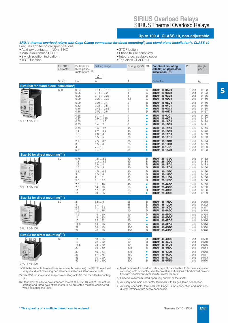
Siemens LV 10 · 2004 5/41
SIRIUS Overload RelaysSIRIUS Thermal Overload Relays
Up to 100 A, CLASS 10, non-adjustable
5
3RU11 thermal overload relays with Cage Clamp connection for direct mounting1) and stand-alone installation2), CLASS 10Features and technical specifications• Auxiliary contacts: 1 NO + 1 NC • Manual/automatic RESET • Switch position indication • TEST function
• STOP button • Phase failure sensitivity • Integrated, sealable cover • Trip class CLASS 10
1) With the suitable terminal brackets (see Accessories) the 3RU11 overload relays for direct mounting can also be installed as stand-alone units.
2) Size S00 for screw and snap-on mounting onto 35 mm standard mounting rail.
3) Standard value for 4-pole standard motors at AC 50 Hz 400 V. The actual starting and rated data of the motor to be protected must be considered when selecting the units.
4) Maximum fuse for overload relay, type of coordination 2. For fuse values for mounting onto contactor, see Technical specifications "Short-circuit protec-tion with fuses/circuit-breakers for motor feeders".
5) Observe maximum rated operating current of the units.
6) Auxiliary and main conductor terminals with Cage Clamp connection.
7) Auxiliary conductor terminals with Cage Clamp connection and main con-ductor terminals with screw connection.
For 3RT1 contactor
Suitable for three-phase motors with P3)
Setting range Fuse gL/gG4) DT For direct mounting (S0–S3) or stand-alone installation 1)2)
PS* Weight per PU
Size5) kW A A Order No. kg
Size S00 for stand-alone installation6)
3RU11 16-..C1
S00 0.04 0.11 ... 0.16 0.5 C 3RU11 16-0AC1 1 unit 0.1830.06 0.14 ... 0.2 1 C 3RU11 16-0BC1 1 unit 0.1830.06 0.18 ... 0.25 1 B 3RU11 16-0CC1 1 unit 0.1860.09 0.22 ... 0.32 1.6 C 3RU11 16-0DC1 1 unit 0.186
0.09 0.28 ... 0.4 2 B 3RU11 16-0EC1 1 unit 0.1860.12 0.35 ... 0.5 2 B 3RU11 16-0FC1 1 unit 0.1860.18 0.45 ... 0.63 2 3RU11 16-0GC1 1 unit 0.1850.18 0.55 ... 0.8 4 B 3RU11 16-0HC1 1 unit 0.187
0.25 0.7 ... 1 4 3RU11 16-0JC1 1 unit 0.1860.37 0.9 ... 1.25 4 3RU11 16-0KC1 1 unit 0.1870.55 1.1 ... 1.6 6 3RU11 16-1AC1 1 unit 0.1880.75 1.4 ... 2 6 3RU11 16-1BC1 1 unit 0.191
0.75 1.8 ... 2.5 10 3RU11 16-1CC1 1 unit 0.1891.1 2.2 ... 3.2 10 3RU11 16-1DC1 1 unit 0.1901.5 2.8 ... 4 16 3RU11 16-1EC1 1 unit 0.1891.5 3.5 ... 5 20 3RU11 16-1FC1 1 unit 0.193
2.2 4.5 ... 6.3 20 3RU11 16-1GC1 1 unit 0.1943 5.5 ... 8 25 3RU11 16-1HC1 1 unit 0.1894 7 ... 10 35 3RU11 16-1JC1 1 unit 0.1935.5 9 ... 12 35 3RU11 16-1KC1 1 unit 0.193
Size S0 for direct mounting1)7)
3RU11 16-..D0
S0 0.75 1.8 ... 2.5 10 B 3RU11 26-1CD0 1 unit 0.1821.1 2.2 ... 3.2 10 B 3RU11 26-1DD0 1 unit 0.1841.5 2.8 ... 4 16 B 3RU11 26-1ED0 1 unit 0.1831.5 3.5 ... 5 20 B 3RU11 26-1FD0 1 unit 0.186
2.2 4.5 ... 6.3 20 B 3RU11 26-1GD0 1 unit 0.1863 5.5 ... 8 25 B 3RU11 26-1HD0 1 unit 0.1844 7 ... 10 35 B 3RU11 26-1JD0 1 unit 0.1865.5 9 ... 12.5 35 B 3RU11 26-1KD0 1 unit 0.186
7.5 11 ... 16 40 3RU11 26-4AD0 1 unit 0.1887.5 14 ... 20 50 3RU11 26-4BD0 1 unit 0.18811 17 ... 22 63 B 3RU11 26-4CD0 1 unit 0.18611 20 ... 25 63 3RU11 26-4DD0 1 unit 0.189
Size S2 for direct mounting1)7)
3RU11 36-..D0
S2 3 5.5 ... 8 25 B 3RU11 36-1HD0 1 unit 0.3184 7 ... 10 35 B 3RU11 36-1JD0 1 unit 0.3225.5 9 ... 12.5 35 B 3RU11 36-1KD0 1 unit 0.3177.5 11 ... 16 40 B 3RU11 36-4AD0 1 unit 0.318
7.5 14 ... 20 50 B 3RU11 36-4BD0 1 unit 0.32411 18 ... 25 63 3RU11 36-4DD0 1 unit 0.32215 22 ... 32 80 3RU11 36-4ED0 1 unit 0.316
18.5 28 ... 40 80 3RU11 36-4FD0 1 unit 0.32622 36 ... 45 100 B 3RU11 36-4GD0 1 unit 0.33022 40 ... 50 100 B 3RU11 36-4HD0 1 unit 0.326
Size S3 for direct mounting1)7)
3RU11 46-..D0
S3 11 18 ... 25 63 B 3RU11 46-4DD0 1 unit 0.55815 22 ... 32 80 B 3RU11 46-4ED0 1 unit 0.54818.5 28 ... 40 80 B 3RU11 46-4FD0 1 unit 0.55622 36 ... 50 125 B 3RU11 46-4HD0 1 unit 0.554
30 45 ... 63 125 3RU11 46-4JD0 1 unit 0.55837 57 ... 75 160 3RU11 46-4KD0 1 unit 0.57745 70 ... 90 160 3RU11 46-4LD0 1 unit 0.57345 80 ... 100 200 B 3RU11 46-4MD0 1 unit 0.570
* This quantity or a multiple thereof can be ordered.
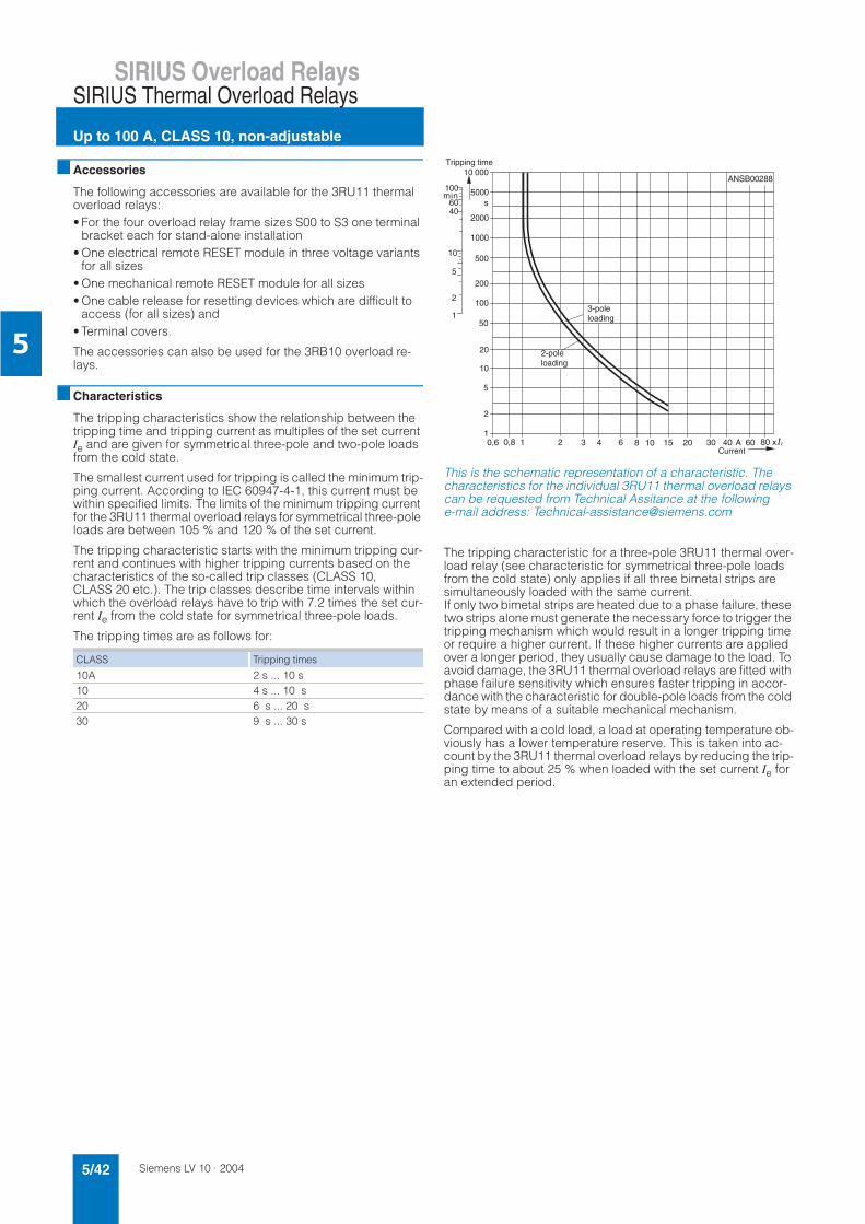
Siemens LV 10 · 20045/42
SIRIUS Overload Relays
Up to 100 A, CLASS 10, non-adjustable
SIRIUS Thermal Overload Relays
5
Accessories
The following accessories are available for the 3RU11 thermal overload relays:• For the four overload relay frame sizes S00 to S3 one terminal
bracket each for stand-alone installation• One electrical remote RESET module in three voltage variants
for all sizes• One mechanical remote RESET module for all sizes• One cable release for resetting devices which are difficult to
access (for all sizes) and• Terminal covers.
The accessories can also be used for the 3RB10 overload re-lays.
Characteristics
The tripping characteristics show the relationship between the tripping time and tripping current as multiples of the set current Ie and are given for symmetrical three-pole and two-pole loads from the cold state.
The smallest current used for tripping is called the minimum trip-ping current. According to IEC 60947-4-1, this current must be within specified limits. The limits of the minimum tripping current for the 3RU11 thermal overload relays for symmetrical three-pole loads are between 105 % and 120 % of the set current.
The tripping characteristic starts with the minimum tripping cur-rent and continues with higher tripping currents based on the characteristics of the so-called trip classes (CLASS 10, CLASS 20 etc.). The trip classes describe time intervals within which the overload relays have to trip with 7.2 times the set cur-rent Ie from the cold state for symmetrical three-pole loads.
The tripping times are as follows for:
This is the schematic representation of a characteristic. The characteristics for the individual 3RU11 thermal overload relays can be requested from Technical Assitance at the following e-mail address: [email protected]
The tripping characteristic for a three-pole 3RU11 thermal over-load relay (see characteristic for symmetrical three-pole loads from the cold state) only applies if all three bimetal strips are simultaneously loaded with the same current. If only two bimetal strips are heated due to a phase failure, these two strips alone must generate the necessary force to trigger the tripping mechanism which would result in a longer tripping time or require a higher current. If these higher currents are applied over a longer period, they usually cause damage to the load. To avoid damage, the 3RU11 thermal overload relays are fitted with phase failure sensitivity which ensures faster tripping in accor-dance with the characteristic for double-pole loads from the cold state by means of a suitable mechanical mechanism.
Compared with a cold load, a load at operating temperature ob-viously has a lower temperature reserve. This is taken into ac-count by the 3RU11 thermal overload relays by reducing the trip-ping time to about 25 % when loaded with the set current Ie for an extended period.
CLASS Tripping times
10A 2 s ... 10 s10 4 s ... 10 s20 6 s ... 20 s30 9 s ... 30 s
10
100
1000
10 000
5000
2000
500
200
50
20
5
2
1
1
2
5
10
4060
100
0,6 0,8 1 2 3 4 6 8 10 20 30 40 60 80 x nA
s
15
NSB00288
Tripping time
3-poleloading
2-poleloading
Current
A
min
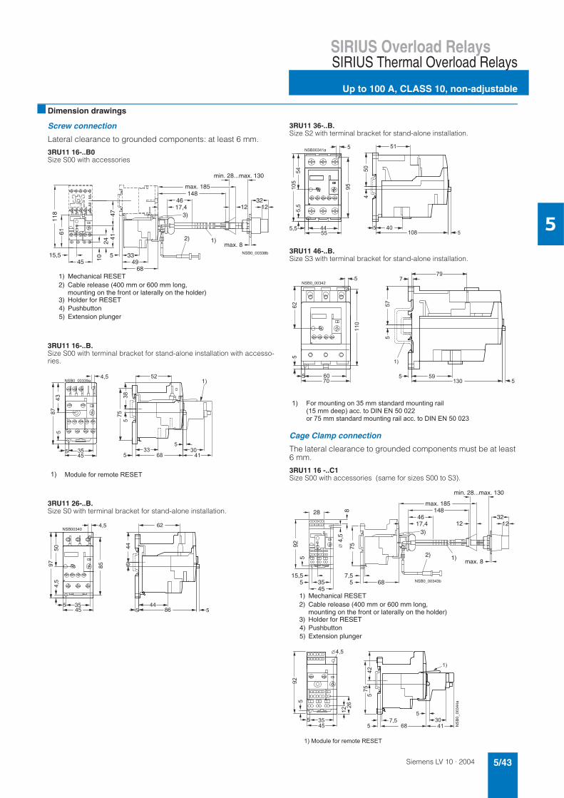
Siemens LV 10 · 2004 5/43
SIRIUS Overload RelaysSIRIUS Thermal Overload Relays
Up to 100 A, CLASS 10, non-adjustable
5
Dimension drawings
Screw connection
Lateral clearance to grounded components: at least 6 mm.
3RU11 16-..B0Size S00 with accessories
3RU11 16-..B.Size S00 with terminal bracket for stand-alone installation with accesso-ries.
3RU11 26-..B.Size S0 with terminal bracket for stand-alone installation.
3RU11 36-..B.Size S2 with terminal bracket for stand-alone installation.
3RU11 46-..B.Size S3 with terminal bracket for stand-alone installation.
Cage Clamp connection
The lateral clearance to grounded components must be at least 6 mm.
3RU11 16 -..C1Size S00 with accessories (same for sizes S00 to S3).
15,5
6111
8
1024
4147
455 33
4968
max. 185148
17,446
min. 28...max. 130
1232
12
max. 82) 1)
3)
NSB0_00338b
Cable release (400 mm or 600 mm long, mounting on the front or laterally on the holder)
2)Mechanical RESET1)
Holder for RESET3)Pushbutton4)Extension plunger5)
2 &
%
3
%
! 0 ' 4 4 + 2
NSB00340
445
5 35
85
45
4,5
9750
4,5
446
86
62
5
2
&
%
%
% &
%
2 5 / # / !6 2 ) 7 4 % # / ! ) 7 4
45355
15,5
925
84,
5
75
57,5
68
28
2) 1)
3)
max. 8
min. 28...max. 130
12 123246
17,4
max. 185148
NSB0_00343b
Cable release (400 mm or 600 mm long, mounting on the front or laterally on the holder)
2)Mechanical RESET1)
Holder for RESET3)Pushbutton4)Extension plunger5)
2
&
3
% 3
%
2 ! 0 ' 4 4 +
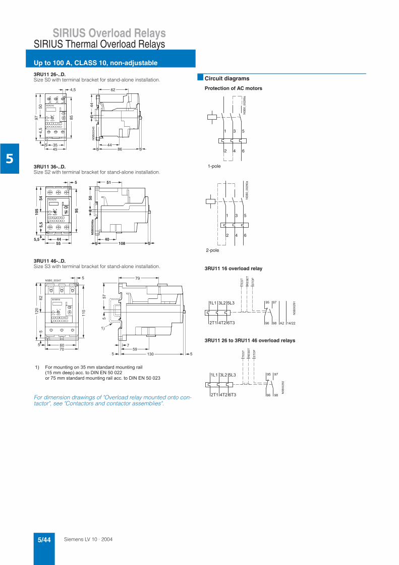
Siemens LV 10 · 20045/44
SIRIUS Overload Relays
Up to 100 A, CLASS 10, non-adjustable
SIRIUS Thermal Overload Relays
5
3RU11 26-..D.Size S0 with terminal bracket for stand-alone installation.
3RU11 36-..D.Size S2 with terminal bracket for stand-alone installation.
3RU11 46-..D.Size S3 with terminal bracket for stand-alone installation.
For dimension drawings of "Overload relay mounted onto con-tactor", see "Contactors and contactor assemblies".
Circuit diagrams
Protection of AC motors
3RU11 16 overload relay
3RU11 26 to 3RU11 46 overload relays
H A
RESETSTOP
TEST0 1
4,5
9750
3545
5
85
5
644
8644
5
4,5 62N
SB
0034
5
%
%
&
% &
%
8
' 4 4 + + 9 :
+ 4 +
%
2
2 5 / # / !6 2 ) 7 4 % # / ! ) 7 4
NS
B0_
0028
9a
4 62
1 3 5
1-pole
NS
B0_
0029
0a
4 62
1 3 5
2-pole
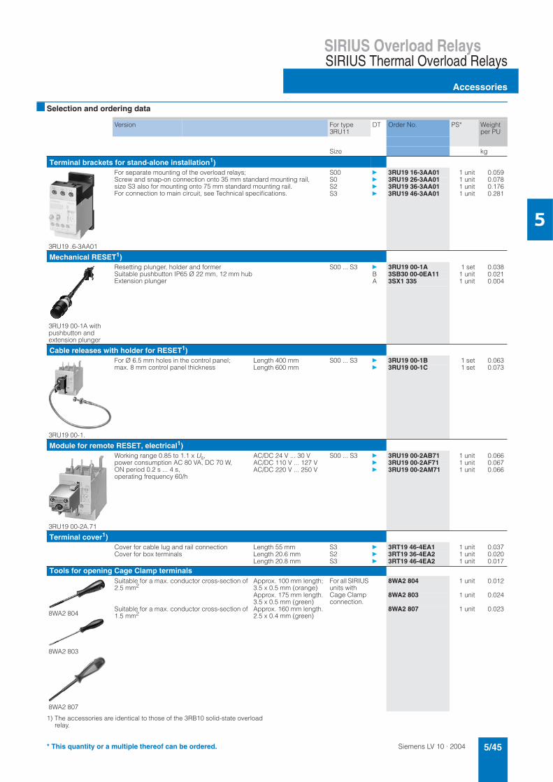
Siemens LV 10 · 2004 5/45
SIRIUS Overload RelaysSIRIUS Thermal Overload Relays
Accessories
5
Selection and ordering data
1) The accessories are identical to those of the 3RB10 solid-state overload relay.
Version For type 3RU11
DT Order No. PS* Weight per PU
Size kg
Terminal brackets for stand-alone installation1)
3RU19 .6-3AA01
For separate mounting of the overload relays; Screw and snap-on connection onto 35 mm standard mounting rail, size S3 also for mounting onto 75 mm standard mounting rail. For connection to main circuit, see Technical specifications.
S00 3RU19 16-3AA01 1 unit 0.059S0 3RU19 26-3AA01 1 unit 0.078S2 3RU19 36-3AA01 1 unit 0.176S3 3RU19 46-3AA01 1 unit 0.281
Mechanical RESET1)
3RU19 00-1A with pushbutton and extension plunger
Resetting plunger, holder and formerSuitable pushbutton IP65 Ø 22 mm, 12 mm hubExtension plunger
S00 ... S3 3RU19 00-1A 1 set 0.038B 3SB30 00-0EA11 1 unit 0.021A 3SX1 335 1 unit 0.004
Cable releases with holder for RESET1)
3RU19 00-1.
For Ø 6.5 mm holes in the control panel; max. 8 mm control panel thickness
Length 400 mm S00 ... S3 3RU19 00-1B 1 set 0.063Length 600 mm 3RU19 00-1C 1 set 0.073
Module for remote RESET, electrical1)
3RU19 00-2A.71
Working range 0.85 to 1.1 x Us,power consumption AC 80 VA, DC 70 W, ON period 0.2 s ... 4 s, operating frequency 60/h
AC/DC 24 V ... 30 V S00 ... S3 3RU19 00-2AB71 1 unit 0.066AC/DC 110 V ... 127 V 3RU19 00-2AF71 1 unit 0.067AC/DC 220 V ... 250 V 3RU19 00-2AM71 1 unit 0.066
Terminal cover1)Cover for cable lug and rail connection Length 55 mm S3 3RT19 46-4EA1 1 unit 0.037Cover for box terminals Length 20.6 mm S2 3RT19 36-4EA2 1 unit 0.020
Length 20.8 mm S3 3RT19 46-4EA2 1 unit 0.017
Tools for opening Cage Clamp terminals
8WA2 804
8WA2 803
8WA2 807
Suitable for a max. conductor cross-section of 2.5 mm2
Approx. 100 mm length;3.5 x 0.5 mm (orange)
For all SIRIUS units with Cage Clamp connection.
8WA2 804 1 unit 0.012
Approx. 175 mm length. 3.5 x 0.5 mm (green)
8WA2 803 1 unit 0.024
Suitable for a max. conductor cross-section of 1.5 mm2
Approx. 160 mm length. 2.5 x 0.4 mm (green)
8WA2 807 1 unit 0.023
* This quantity or a multiple thereof can be ordered.
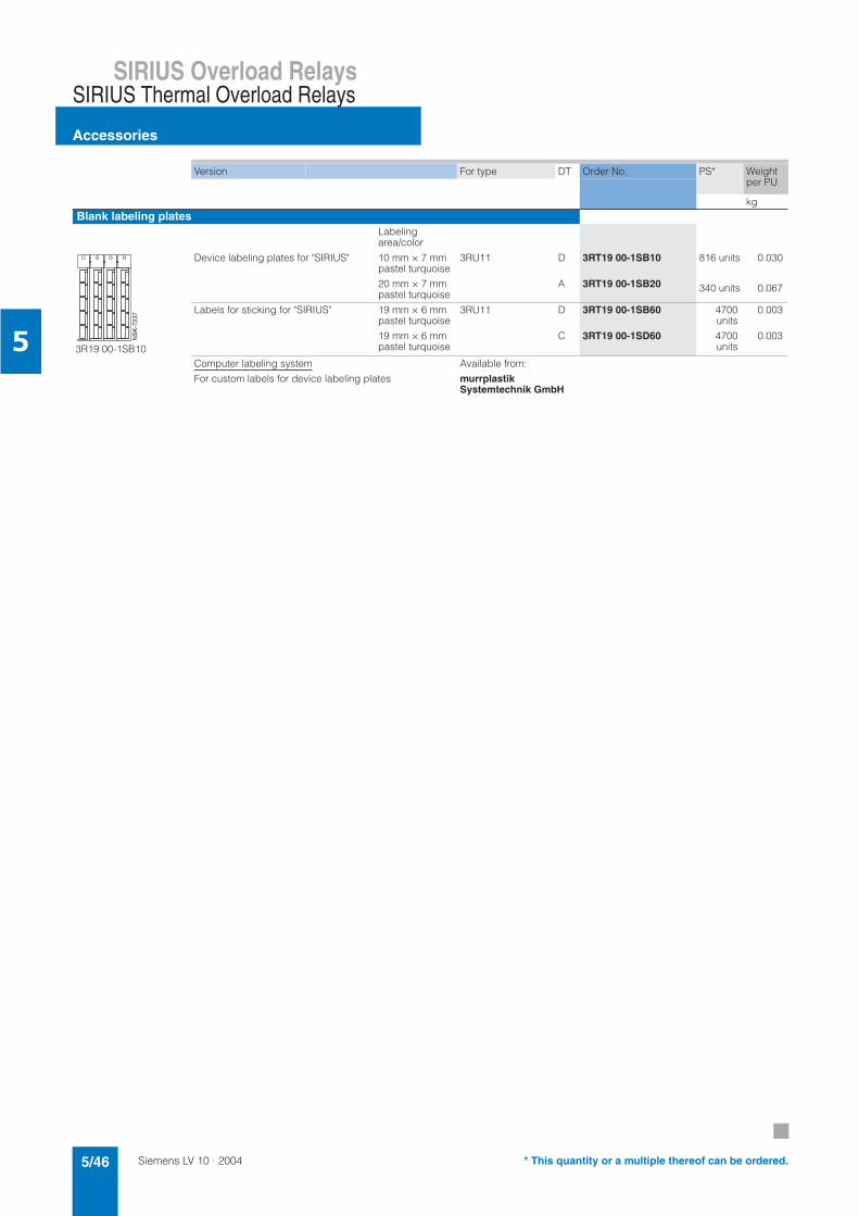
Siemens LV 10 · 20045/46
SIRIUS Overload Relays
Accessories
SIRIUS Thermal Overload Relays
5
Version For type DT Order No. PS* Weight per PU
kgBlank labeling plates
Labeling area/color
3R19 00-1SB10
Device labeling plates for "SIRIUS" 10 mm × 7 mm pastel turquoise
20 mm × 7 mm pastel turquoise
3RU11 D
A
3RT19 00-1SB10
3RT19 00-1SB20
816 units
340 units
0.030
0.067
Labels for sticking for "SIRIUS" 19 mm × 6 mm pastel turquoise
19 mm × 6 mm pastel turquoise
3RU11 D
C
3RT19 00-1SB60
3RT19 00-1SD60
4700units
4700units
0.003
0.003
Computer labeling system
For custom labels for device labeling plates
Available from:
murrplastikSystemtechnik GmbH
NS
K-7
237
* This quantity or a multiple thereof can be ordered.