solid oxide fuel cell balance of plant and stack … oxide fuel cell balance of plant ... general...
TRANSCRIPT

Solid Oxide Fuel Cell Balance of Plant & Stack Component Integration
Norman Bessette Acumentrics Corporation
March 16, 2010

Acumentrics Corporation
•Based in Westwood, Mass. •~40,000 sq. ft facility •Profitable • Critical disciplines in-house
El t i l E i i
Strategic Partners
Electrical Engineering Mechanical Engineering Chemical Engineering Thermal Modeling Ceramics Processing Manufacturing Sales & Marketing Automation Finance
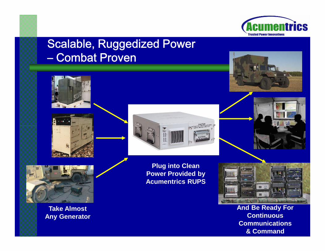
Scalable, Ruggedized Power – Combat Proven
Take Almost Any Generator
Plug into Clean Power Provided by Acumentrics RUPS
And Be Ready For Continuous
Communications & Command

Solar Flare Tests RUPS to 170˚FSolar Flare Tests RUPS to 170˚F –– 16 hours continuous16 hours continuous General Atomics SkyWarriorGeneral Atomics SkyWarrior

Fuel Cells • Made from low-cost nickel oxide • Uses available fuels: natural gas, propane, synthetic
JP-8 • 41 units delivered to the field • Twice the efficiency of equivalent generatorsTwice the efficiency of equivalent generators
Stacks during assembly Micro-CHP unit for shipment

How Our Fuel Cell Works

Total System Tubular Cells
– Inherent strength andtolerance to rapid temperature change
High Operating Temperature (800 C)(800 C)
– Internal fuel reforming and cogeneration opportunity
Standard ManufacturingProcess
– Low capex Standard Components
– Standard HVAC balance-of-plant components
– Leverage 16 years DC/ACconversion experience

Fuel Cell ManufacturingFuel Cell Manufacturing Isostatic Press Automated dip-coating
Automated Cathode Coating
Plasma spray High Temperature Firing
•Facility Capable of 176kW/yr •Multiple FC Size Capability •No outside Fabrication Steps

Stack Size Reduction Number of tubes
for 1.25 kW reduced from 126 to 72 to 45
Weight reduced 75% from 92 to 23lbs
Volume reduced 82% from 1.55 to 0.28 cu. ft.

Automated dip-coating
100
120
140
Progress of Single Cell Power at Acumentrics
2.2 cm OD (88 cm total length)September 2007 >120W
2.2 cm OD (88 cm total length) September 2007
2.2 cm OD (45 cm total length) February 2010 129W
Automated dip-coating
2.2 cm OD (88 cm total length)
September 20
•Facility Capable of 176kW/yr•Multiple FC Size Capability•No outside Fabrication Steps
0
20
40
60
80
0 50 100 150 200 250 300Cell Current, A
Cel
l Pow
er, W
Electrolyte Supported Cells- Through December 2001
0.7cm Anode Supported Tubes - January 2002-December 20031.5cm (33 cm length) Anode Supported Tubes- 75%FU December 2003-June 2005
1.5cm anode supported tube with LaCrO3 IC- July 2005-November 2005
1.5cm (42cm length) LaCrO3 IC Anode Supported Tubes-December 2005
Two 2.2cm OD Anode Supported Tubes-January 2007
•Facility Capable of 176kW/yr•Multiple FC Size Capability•No outside Fabrication Steps
Cell Performance ProgressCell Performance Progress
100
120
140
Progress of Single Cell Power at Acumentrics
07 >120W
2.2 cm OD (88 cm total length) September 2007
2.2 cm OD (45 cm total length) February 2010 129W
October 1, 2009
0
20
40
60
80
0 50 100 150 200 250 300 Cell Current, A
Cel
l Pow
er, W
Electrolyte Supported Cells-T hrough December 2001
0.7cm Anode Supported Tubes -Janua ry 2002-December 2003 1.5cm (33 cm length) Anode Supported Tubes-75% FU December 2003-June 2005
1.5cm anode supported tube with LaCrO3 IC-J uly 2005-November 2005
1.5cm (42cm length) LaCrO3 IC Anode Supported Tubes-December 2005
Two 2.2cm OD Anode Supported Tubes-January 2007

0.339
0.403
0.35
0.4
0.45
cm -2
Cell Performance ProgressCell Performance Progress
0.072
0.099
0.261
0
0.05
0.1
0.15
0.2
0.25
0.3
Pow
er D
ensi
ty a
t 0.7
V, W
2004 2005 2006 2007 2010

ProductsProducts

mCHPmCHP vs.vs. power plant and (condensing) boilerpower plant and (condensing) boiler
Power plant heating
Primary energy 100%
Primary energy 100%
Losses
Losses
microCHP
microCHP simultaneous power and heat production
56% heat
16% power24%
4%
60%40%
72% useful energy
90% useful energy
Losses
Common technologyseparate power and heat production
20% power
70% heat
10%
= 10= 10 –– 25% lower primary energy consumption25% lower primary energy consumption = 10= 10 –– 25% lower CO25% lower CO22 emissionsemissions = 10= 10 –– 25% lower energy cost25% lower energy cost

MTS Wall Mounted mCHPMTS Wall Mounted mCHP
One kilowatt unit with 20 kW thermal boiler Huge achievement to meet space and weight requirements 80-90% total efficiency, 33”x22”x18” 180lb total, 100lb FC sys

t
CHP ApplianceCHP Appliance • Wall-mount
design for apartments and condos; larger fl dfloor mounted design
• Tankless water heater
• Incidental power while heating
• Easy on-off • Multiple
prototypes delivered

DC/DC Converter
mCHP LayoutmCHP Layout
Recuperator
ID Fan
Controller
Fuel Cell
Peak Boiler Inverter
BatteriesDesulfurizer

European Trials • “Open” lab trials • Demo with major European
utilities • Demonstration &
Commercialization Programwith Consortium of utilities
1 Booster Boiler 2 Fuel Cell Stack 3 Exhaust Heat Exchanger 4 Fuel desulfurizer

JPJP--8 Fueled 10kW Generator8 Fueled 10kW Generator
108 cell
Cathode Air
Electronics
Condenser Fan
Desulfurizer
108 cell stack
Electronics
Condenser
Pre cooler Batteries
40kWT reformer
Filter

BalanceBalance of Plant Developmentof Plant Development NNeedseeds
Lack of modulating venturi mix valves for continuous operation
Lack of low cost combustion blowers with the necessaryy hours for mCHP life
Lack of low pressure drop flow meters, especiallyfuel, for economic solution.
Low cost NG & LPG sulfur detector Metering pumps for liquid fuel operations extremely
expensive and unproven life. Should note that the average 20yr home furnace only
runs 20,000hrs

t
PowerPower Electronic Development NeedsElectronic Development Needs
For $500-$750/kW factory cost, inverters can not cost more that $100/kW Solar inverters in 2-3kW range are presently
$600 $900/kW d $800 $1400/kW$600-$900/kW cost and $800-$1400/kWpriceThe battle of high efficiency and low cost
requires integrated design and key trade-offs. Fuel cell inverters not only provide DC/AC
conversion but also a DC bus for parasitics

Stack Integration Development NeedsStack Integration Development Needs
High temperature, high conductivity, low cost wire Thin wall, high strength composite refractory
materials - mica replacement or joiningp j gtechnique High temperature, non-conductive
temperature sensors Low cost, insulation panels with air jacketing Low Cost Recuperators

Recuperator SizesRecuperator Sizes 300 cu. in.
REQUIREMENTS 17.8 lbs Exhaust Inlet Temperature –
850 - 950 C Air Outlet Temperature – 725 - 800 C Effectiveness – >85% Total Pres Drop – 1250 Pa Equal Air & Exhaust Flows Air Flow – 150 Slpm/ kWe
100 cu. in. +100,000 Hours & Hundreds of Thermal 3.8 lbs Cycles

p p y g
ManufacturingManufacturing Development NeedsDevelopment Needs
DOE has historically not funded manufacturing development in SOFC programs (though they have in PEM)
As opposed to many PEM developers who buy MEA components, SOFC developers tend to be vertically integrated.
Automation of cell processing in the SOFC industry is severelybehind the level which may be observed for other fuel cell types such as PEM, leading to unnecessarily high cell costs.
Funds to address scale-up and automation issues in the SOFC industry are limited due to inherent high costs and low ROI. This currently poses one of the most significant barriers to entryfor widespread commercialization of SOFC.

DemonstrationDemonstration NeedsNeeds
Has been a limited opportunity for funding ofdemonstration units. Very few solicitations have had more than 1-2
units covered always at 50%units covered, always at 50% Should allow for a 10-20 unit demonstration
program to allow for significant statistics and different operating cases. Large demonstration populations would allow
for economy of scale on manufacturing and abetter ability to get customers to cover the necessary 50% cost share.
ConclusionsConclusions • Good progress being made in mCHP
development on all major subsystems and life.
• There is a need for R&D funding around bothcomponent development and Demonstrations
• Long term there will be a need to create thesame subsidies that have launched the solar industry while still providing R&D dollars.