general atomics low-speed urban maglev technology ... atomics 2003.pdf · the general atomics low...
TRANSCRIPT
Sam Gurol, Bob Baldi, Richard Post 1
3311 words
The General Atomics Low Speed Urban Maglev Technology Development Program
Sam Gurol and Bob Baldi General Atomics P.O. Box 85608, San Diego, CA, 92186-5608, USA (858) 455-4113/Fax (858) 455-4341, [email protected], [email protected] Richard F. Post Lawrence Livermore National Laboratory P.O. Box 808, Mail Stop L-644, Livermore, CA 94551, USA (925) 422-9853/Fax (925) 423-7914, [email protected] Keywords EDS, Maglev, Urban Maglev
ABSTRACT
The overall objective of this program is to develop magnetic levitation technology that is a cost effective, reliable, and environmentally friendly option for urban mass transportation in the United States. Maglev is a revolutionary approach in which trains are supported by magnetic forces without any wheels contacting the rail surfaces. The Urban Maglev Program is sponsored by the Federal Transit Administration and funded under the Transportation Equity Act for the 21st Century (TEA-21). An innovative approach for Urban Maglev has emerged that involves an entirely passive, permanent magnet levitation system with an efficient linear synchronous motor powering the guideway to provide propulsion. The system is unique in that operates with a large air gap of 25 mm with no feedback control required for stable levitation; furthermore, the packaging of the levitation magnets allows the vehicle to accommodate a very tight turn radius of 18.3 m. The studies show that the General Atomics Urban Maglev system offers many attractive benefits, including very quiet operation, the ability to operate in challenging terrain with steep grades and tight turns, all-weather operation, low maintenance, rapid acceleration, and the potential for high speed.
1 INTRODUCTION
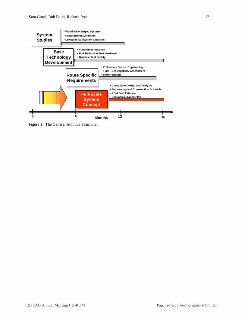
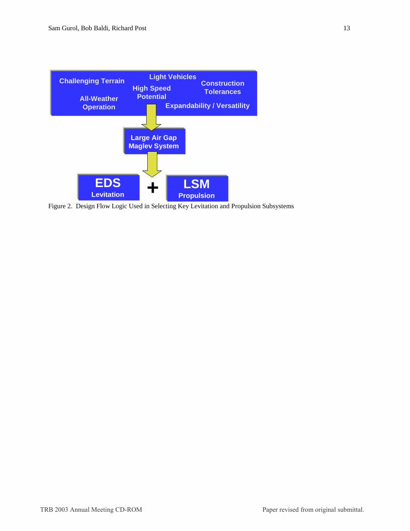
Significant progress has been achieved in the areas of system studies, base technology development, route-specific analysis, and full-scale system concept development (including costs, schedule and commercial planning). Figure 1 shows key activities in the first 18 months of the program. Current activities are focused on testing prototype components to confirm predicted levitation, propulsion, and guidance forces, and to validate the developed computational tools. “System Studies” started with review of the state of maglev systems built around the world, followed by preparation of a detailed system requirements document. The system requirements document is divided into three sections: general requirements, alignment description, and specific requirements. A summary of key system parameters is presented in Table 1. This task also evaluated four different levitation subsystems, as well as comparing linear induction motor (LIM) propulsion with linear synchronous motor (LSM) propulsion. The design flow logic for the process, which culminated in the selection of an electrodynamic (EDS) levitation system with a LSM propulsion system, is schematically represented in Figure 2. The capability of a maglev system to operate with a “large air gap”, in the range of 25 mm, provides potential benefits, such as its ability to operate in all weather conditions, as well as being less sensitive to guideway construction tolerances. The result was the selection of permanent magnet Halbach arrays for levitation (1,2) and a guideway-mounted LSM for propulsion. “Base Technology Development” included a number of risk reduction analyses, as well as building several test articles. Examples of some of the test articles built for reducing technology development risks includes a subscale and full-scale test wheel to verify levitation physics.
TRB 2003 Annual Meeting CD-ROM Paper revised from original submittal.
Sam Gurol, Bob Baldi, Richard Post 2
Based on route specific requirements, a full-scale system concept has been developed. Current on-going activities include performing laboratory testing of key components to validate the design and the computational tools, which have been developed during this project. The next steps beyond these activities are to fabricate full-scale prototype track and vehicle chassis systems, and to eventually construct a full-scale demonstration system to evaluate the readiness of the technology for deployment. General Atomics (GA) in San Diego, California manages the Urban Maglev project, backed by a team consisting of companies and organizations with unique strengths and capabilities, particularly suited for a Maglev project, as shown in Table 2. This paper presents an overview of the technical progress to date. Related papers address additional details (3,4,5).
2 REQUIREMENTS OF AN URBAN MAGLEV
A thorough requirements document was prepared during the initial stage of the program. This document creates a common set of guidelines, which is intended to keep the design team focused during the design/development process. Included are requirements for the system and major subsystems to assure the performance, ride comfort and safety of the passengers. Key requirements are listed below in Table 3
3 LEVITATION AND GUIDANCE SYSTEMS
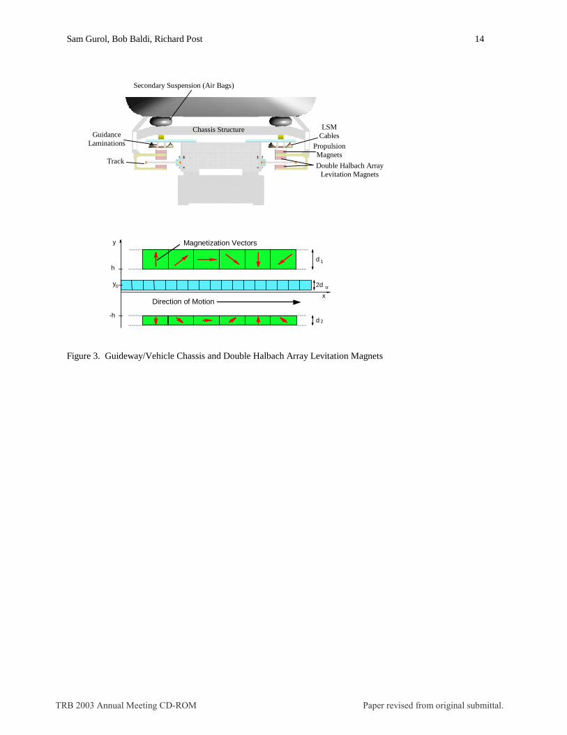
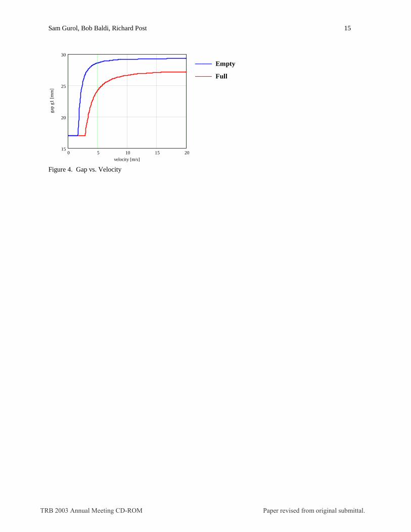
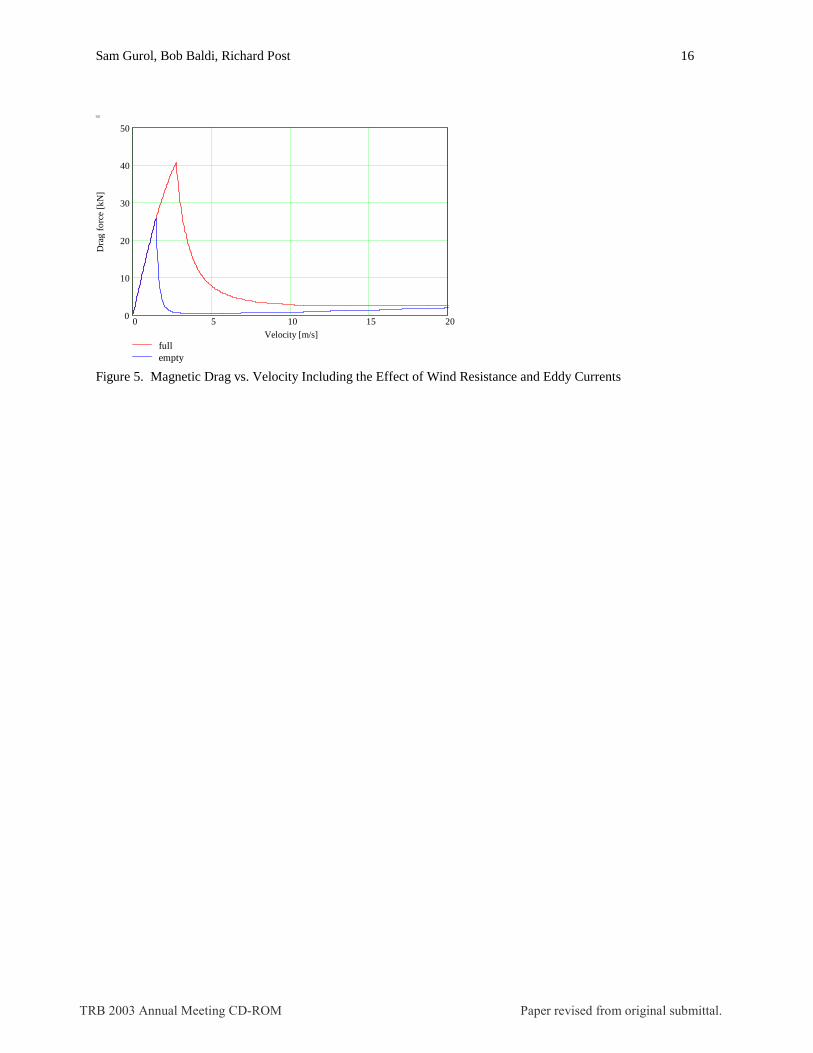
The levitation system uses vehicle mounted permanent magnet double Halbach arrays (1,2). The orientation of the magnetization of the magnets in the Halbach array is arranged such as to concentrate the field lines below the array while nearly canceling the field above the array. This results in a system which requires no active magnetic shielding of the passenger compartment. In a double Halbach array, the strong sides of two Halbach arrays oppose each other with the track in between. The guidance force is provided passively by the propulsion magnets (on the vehicle) interacting with the laminated iron core of the LSM winding (on the guideway). The guideway and vehicle chassis cross-section, as well as the magnetic configuration of the double Halbach array are shown in Figure 3. The vehicle is supported on wheels when stationary, but levitates as it reaches the lift-off speed of about 2.5 meters per second. The air gap increases gradually as the vehicle speed increases, with a nominal levitation gap of 25 mm at a cruising speed of 80 km/hr. Minimization of the magnetic drag was a primary consideration for urban applications with frequent starts and stops. The magnetic drag shows a peak at around the lift-off speed and decreases very rapidly with speed. Figures 4 and 5 show the gap and drag force, respectively, as a function of vehicle speed.
4 RIDE QUALITY
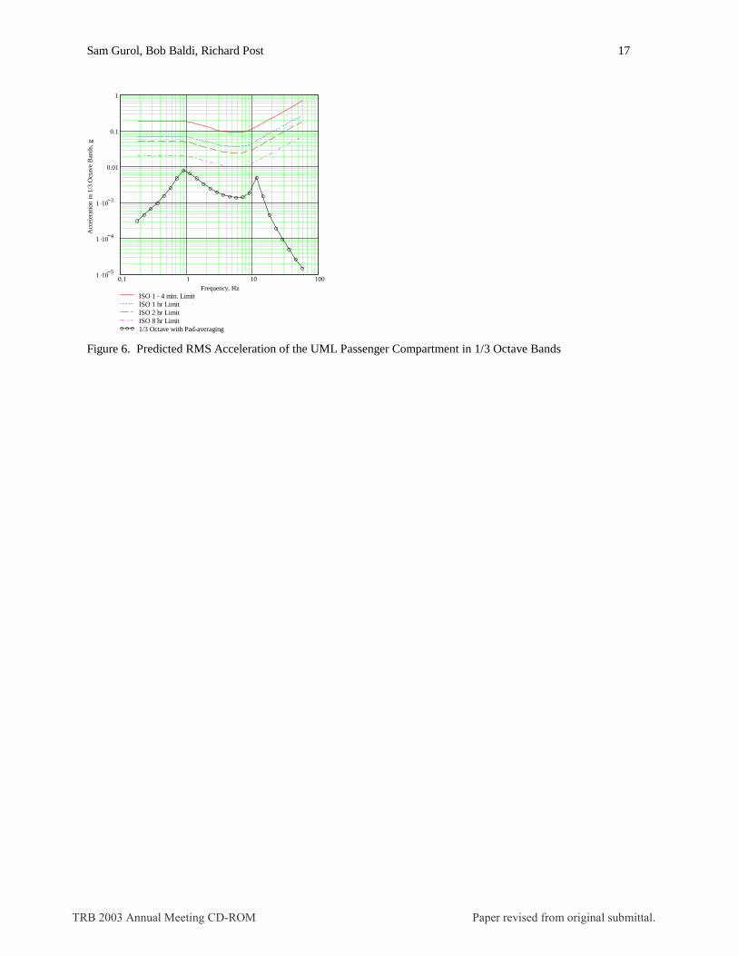
Ride quality and damping are provided by an entirely passive secondary suspension system. This, coupled with the relatively stiff primary (magnetic) suspension provides excellent ride quality and only minimal changes in ride height with passenger load. Six degree of freedom dynamic simulations performed to date have shown no instabilities. Existing models of rail track roughness were used. Actual test track measurements, when available, will be valuable in verifying the vehicle dynamics, and projecting performance to higher speeds. The long (3.6 m) levitating arrays provide a means for minimizing the effects of track perturbations. Calculations show expected passenger compartment accelerations well below the ISO 1-hour comfort limit set forth in the requirements. In fact, the passenger compartment accelerations were below the 8-hour limit (Figure 6).
5 PROPULSION SYSTEM
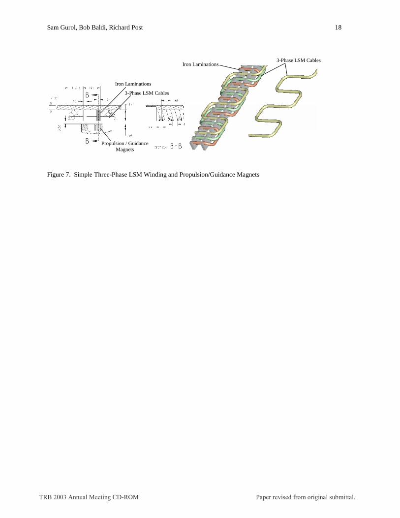
One of our first design decisions focused on selecting the propulsion system. We compared a LIM on the vehicle with a LSM mounted to the guideway. Because of the large operating air gap, a LSM is fundamentally better suited to the needs of an EDS suspension system. It was also found that a LSM is more cost-effective for a high capacity transportation system, which requires many vehicles on the alignment. The LSM configuration chosen also provides the required guidance force as well as additional passive levitation force (~70 kN at nominal air gap). The motor design optimizes the iron geometry to achieve the combined passive guidance and added levitation forces. This additional levitation force helps to reduce the drag force, which in turn reduces the operating power. The LSM design utilizes a simple three-phase winding with solid copper cables, chosen for low cost manufacturing. The LSM winding and propulsion magnets are shown in Figure 7.
TRB 2003 Annual Meeting CD-ROM Paper revised from original submittal.
Sam Gurol, Bob Baldi, Richard Post 3
6 VEHICLE AND GUIDEWAY
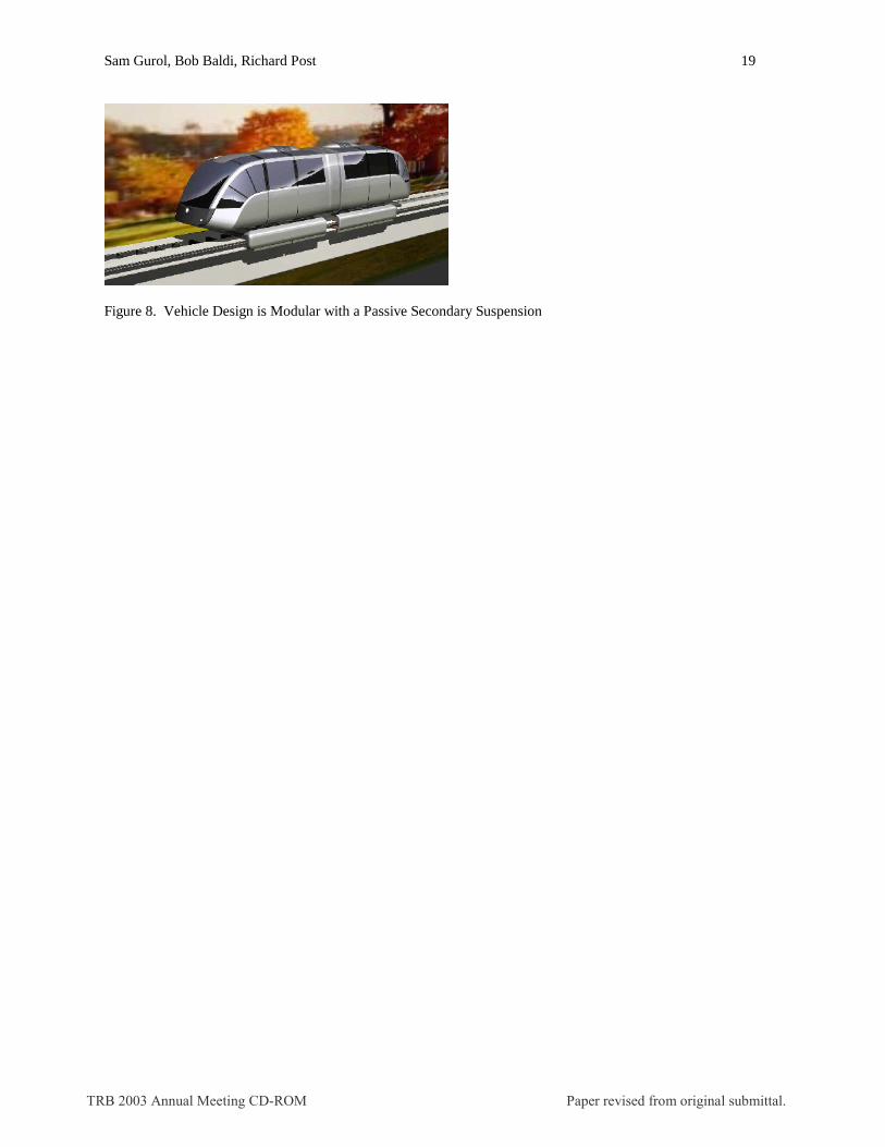
The technology choices of EDS and LSM result in a very simple and lightweight (9.5 metric tons empty) vehicle. The vehicle consists of two modular sections connected via an articulation. The length of the levitation pads (per module) was limited to 3.6 meters to allow tight turn capability (18.3 meters). The vehicle and guideway are shown in Figure 8. Important design parameters are given in Table 4
7 CURRENT TEST PROGRAM
We have been performing testing of key subsystems to validate the forces generated by the levitation, propulsion, and guidance systems, and to confirm our ability to measure the speed and location of the vehicle and to provide the needed control. The test activities are summarized below.
Levitation Optimization
Tests are being performed using the dynamic test facility (described in Section 9) to optimize the geometry of the upper and lower Halbach array magnets for optimum lift to drag values. This will allow greater energy efficiency during acceleration and cruise modes of operation. It will also validate the stiffness of the primary magnetic suspension required for predicting vehicle ride quality and dynamic characteristics.
Static LSM Testing
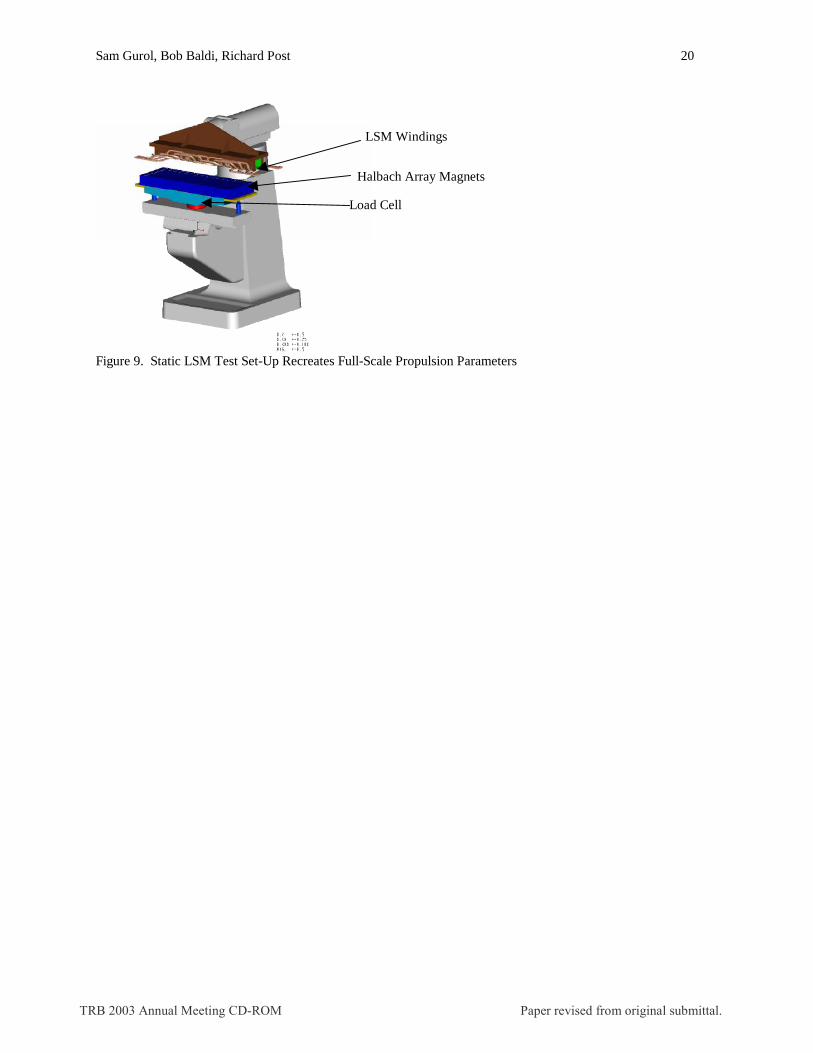
The full-scale LSM (iron rail, winding, and excitation Halbach arrays) has been recreated to verify the parameters used in the LSM design. The LSM test set-up (shown in Figure 9 below) represents 1/18th the length of the LSM windings for a vehicle. A 6 degree-of-freedom load cell is used and is mounted on an existing milling machine so that magnetic fields and forces can be measured at various relative positions between the winding and magnet arrays.
Speed/Location Detection
Speed and location detection of a moving Maglev vehicle has been simulated using the dynamic test facility. A mock-up of the LSM windings has been attached to the concrete wall adjacent to the moving track on the test wheel. A 20 kHz signal (mounted on the moving wheel) is injected into the LSM windings to verify that vehicle speed, distance, and direction can be accurately determined. This technology avoids the use of any trackside sensors, eliminating associated maintenance concerns.
Track Current Measurement
The induced track currents are measured with a test set-up, which uses current detectors placed around consecutive rungs of the track. The current detector employs Ampere’s law. All data are stored in a small battery-powered data logger, which is rotating with the wheel, and then transferred to a computer for processing. The testing validates the electrical properties of the track, which enables accurate predictions of vehicle levitation performance.
Laminated Track Development
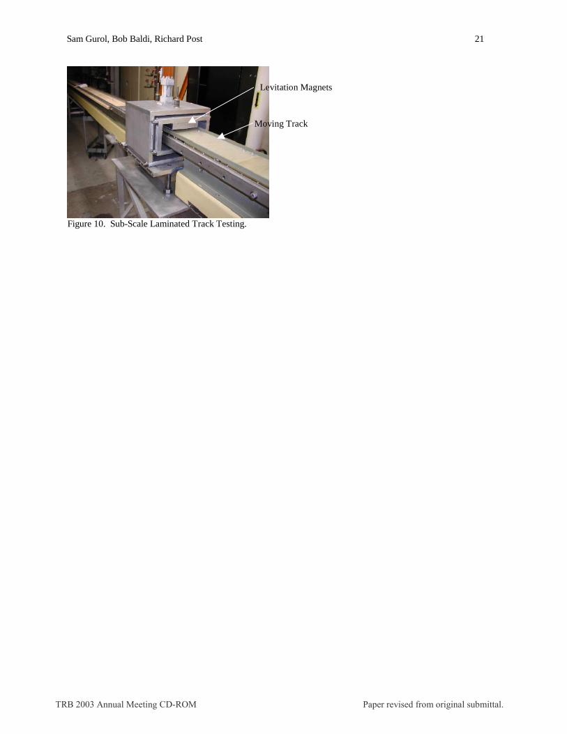
A laminated copper track has emerged during this project as an option that may result in improved levitation performance and lower manufacturing costs. We have built a subscale laminated track test set-up (located at LLNL), which is shown in Figure 10. The levitation magnets are held in a stationary fixture, while the track is pushed past the field generated by the magnets. The magnet fixture is instrumented to record the levitation and drag forces at a fixed (adjustable) air gap.
8 THEORETICAL STUDIES AND ALTERNATIVE DESIGNS
As a part of the Urban Maglev team effort, theoretical studies and examinations of alternative levitation and propulsion designs have been carried out at the Lawrence Livermore National Laboratory. Computer codes have been developed to analyze the present “baseline” configurations, as well as to scope out alternative configurations. Where possible, these codes have been bench-marked against the results of the Dynamic Test Facility (DTF) (see Section 9), finding good agreement. An example of such a comparison is the prediction of the improvement in levitation and Lift/Drag that can be expected in changing the track design from a litz-wire, “ladder” track to a laminated track. The specific comparison that was made was between the code predictions for the litz-wire-based
TRB 2003 Annual Meeting CD-ROM Paper revised from original submittal.
Sam Gurol, Bob Baldi, Richard Post 4
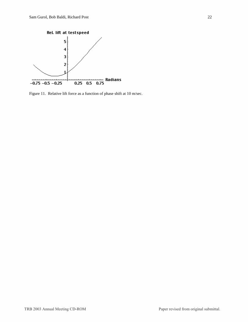
“ladder” track as it is presently configured in the DTF, when operated with a double Halbach array that is five magnets in width on the top array and 3 magnets on the lower array. Still using the same magnet array and the same fixed-gap, the code was then programmed to calculate a 0.01 m. thick (copper) laminated-track configuration. Comparisons were made between such parameters as the levitated weight, L/D, and transition speed. It was found that the laminated track, because of its much higher conductor packing fraction and its smaller thickness (0.01 m. vs. 0.014 m. for the present litz-wire track) can be expected to yield markedly improved performance. Table 5 lists some comparisons between the “fixed-gap” code predictions for the present test facility track and a laminated track having the same transverse width as the present track. Also shown in the table (last column) is the further improvements that can be expected if the width of the laminated track is reduced to 0.3 m from the 0.5 m width of the present (test facility) track. The code predictions for the laminated track are bench-marked by measurements obtained using a linear-track test-rig at LLNL, built specifically for that purpose (Figure 10). The code that was used to predict the above results has also been modified to calculate the effect of introducing a shift in phase of one of the Halbach arrays relative to the other array. This shift has the effect of modifying the “generator action“ of the vertical magnetic field component. The phase-shifting operation is accomplished by displacing the leading edge of one of the arrays relative to the other, and could either be performed as a fixed “trimming” of the levitation force, or could be incorporated into a levitation control circuit if required. The effect of applying such a phase-shift to a double Halbach array in which the upper and lower arrays have the same width as the upper array in the DTF, and with ratio of thickness of the arrays (lower relative to upper) of 0.8 as in the DTF is shown on the plot of Figure 11. As can be seen, even a small positive phase shift can result in a substantial increase in the levitation force. The down side of using a large phase shift is, however, a substantial decrease in the stiffness relative to the un-shifted case. Note also that, initially, a negative phase shift results in a decrease in the levitation force relative to the un-shifted case, owing to the introduction of anisotropy as a function of direction of motion that is implicit in the operation of shifting the phase. At higher speeds this anisotropy is reduced as the electrical phase shift approaches its asymptotic value of 90 degrees.
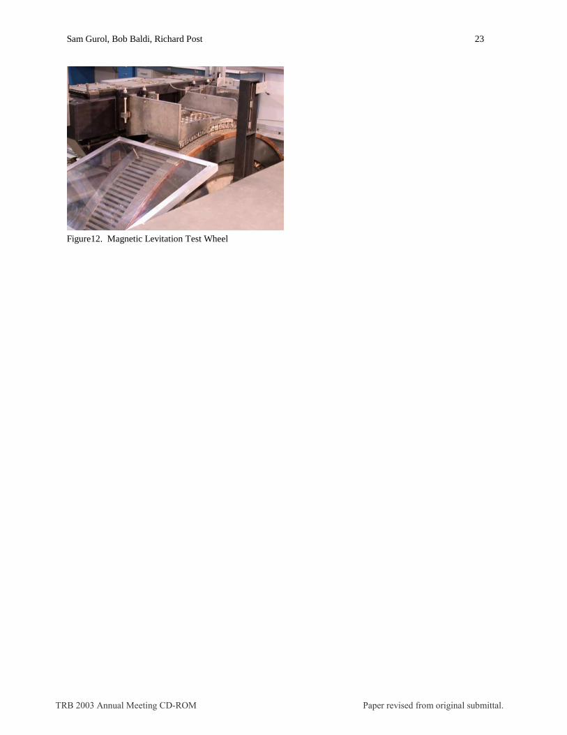
9 MAGNETIC LEVITATION TEST WHEEL
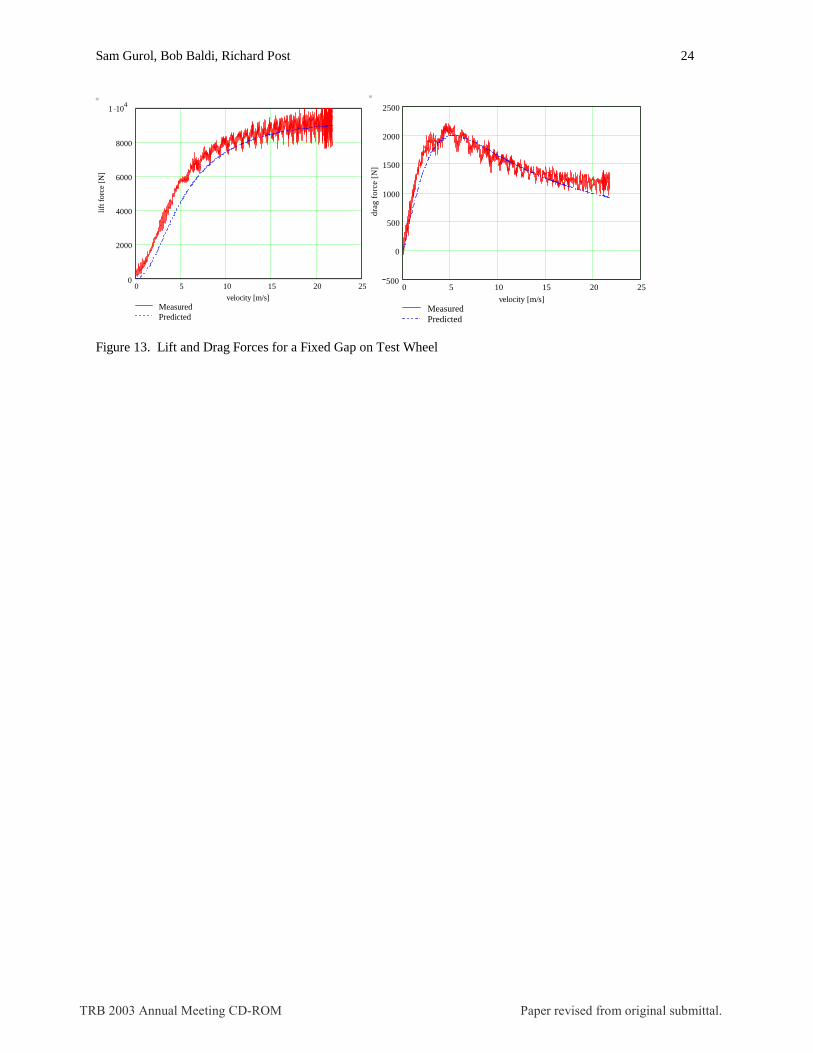
In advance of a full-scale test track, considerable model validation can be done on bench and partial component test apparatus. At present, the device we have built to measure levitation characteristics of the vehicle is a 3 m diameter rotating wheel having a full-scale track at its perimeter. This wheel simulates the magnetics of the double Halbach array moving with respect to the guideway. It uses two wavelengths of the full-scale levitation magnets to demonstrate the levitation and drag forces as a function of speed. The footprint area of the test magnets corresponds to ~1/18th of a complete vehicle levitation magnet system. Testing began in January 2002 and has produced data essential to validating our modeling predictions. Figure 12 shows the test wheel facility, which consists of a programmable powered wheel having a full-scale ladder track around its perimeter. The simulated 1/18th -scale car mass is affixed to a load cell that restricts movement in all directions except the vertical (levitation). Figure 13 shows the measured and predicted lift and drag forces for a 25 mm fixed gap as a function of speed. The observed lift-off speed is ~2.5 m/s, and a final air gap of 25 mm is achieved at a speed of 20 m/s. These test results confirm levitation predictions. Oscillations in the data are due to radial tolerances in the dimension of the test wheel. Scaling the data to expected track dimensions and packing factors, taking into account the passive lift generated by the LSM laminations, and applying the projections to a typical alignment with stations ~1 km apart, results in the average power projection of 50 kW shown in Table 1.
10 CONCLUSIONS
The General Atomics Low Speed Urban Maglev Technology Development Program provides a new approach for low speed transportation suitable for very challenging urban environments. The technology uses simple permanent magnets operating with a large air gap of 25 mm, requires no feedback control for stable levitation, and is able to accommodate a very tight turn radius of 18.3 m. This results in much simpler and lighter vehicles with the ability to operate under severe weather conditions, with guideway tolerance requirements in line with existing civil construction techniques, and provides urban planners flexibility in locating the alignment. Analyses and testing to date give confidence that there are no major technical obstacles to initial demonstration of the system at a test track leading to full-scale deployment at a selected urban site.
TRB 2003 Annual Meeting CD-ROM Paper revised from original submittal.

Sam Gurol, Bob Baldi, Richard Post 5
11 ACKNOWLEDGEMENTS
This paper summarizes the results of a research effort undertaken by General Atomics under Cooperative Agreement No CA-26-7025 to the Office of Research, Demonstration, and Innovation, Federal Transit Administration (FTA). This work was funded by the U. S. Department of Transportation, Federal Transit Administration’s Office of Technology. The interest, insight, and advice of Mr. Venkat Pindiprolu, Mr. Jim LaRusch, and Mr. Quon Kwan are gratefully acknowledged. The valuable comments provided by the representatives of transit agencies, research institutes, and other independent organizations are gratefully acknowledged. Special thanks are due to George Anagnostopoulos of the DOT-Volpe Center, Jim Guarre of BERGER/ABAM Engineers Inc., John Harding of DOT-FRA, Gopal Samavedam of Foster-Miller, David Keever and Roger Hoopengardner of SAIC, Frank Raposa of Raposa Enterprises, and Marc Thompson of Thompson Consulting. The work performed at the University of California Lawrence Livermore National Laboratory was performed under the auspices of the U. S. Department of Energy under Contract W-7405-ENG-48.
12 REFERENCES
1. U.S. Department of Transportation (Federal Transit Administration). Low Speed Maglev Technology Development Program – Final Report, FTA-CA-26-7025-02.1, March 2002.
2. R. F. Post, D. D. Ryutov, “The Inductrack: A Simpler Approach to Magnetic Levitation,” I.E.E.E, Transactions on Applied Superconductivity, 10, 901 (2000)
3. David.W. Doll, Robert D. Blevins, and Dilip Bhadra, “Ride Dynamics of an Urban Maglev,” Maglev 2002 – The 17th International Conference on Magnetically Levitated Systems and Linear Drives; Lausanne, Switzerland, September 3-5, 2002.
4. In-Kun Kim, Robert Kratz, and David W. Doll, “Technology Development for U.S. Urban Maglev,” Maglev 2002, – The 17th International Conference on Magnetically Levitated Systems and Linear Drives; Lausanne, Switzerland, September 3-5, 2002.
5. K. Kehrer, W. McKenna, and W. Shumaker, “Maglev Design for Permanent Magnet Levitation Electrodynamic Suspension (EDS) System,” Maglev 2002– The 17th International Conference on Magnetically Levitated Systems and Linear Drives; Lausanne, Switzerland, September 3-5, 2002.
TRB 2003 Annual Meeting CD-ROM Paper revised from original submittal.

Sam Gurol, Bob Baldi, Richard Post 6
LIST OF TABLES AND FIGURES
Table 1 Key System Parameters Table 2. Urban Maglev Team Members Table 3. Key System Requirements Table 4. Vehicle Design Parameters Table 5. Comparison of Litz Track Performance with Laminated Track Figure 1. The General Atomics Team Plan Figure 2. Design Flow Logic Used in Selecting Key Levitation and Propulsion Subsystems Figure 3. Guideway/Vehicle Chassis and Double Halbach Array Levitation Magnets Figure 4. Gap vs. Velocity Figure 5. Magnetic Drag vs. Velocity Including the Effect of Wind Resistance and Eddy Currents Figure 6. Predicted RMS Acceleration of the UML Passenger Compartment in 1/3 Octave Bands Figure 7. Simple Three-Phase LSM Winding and Propulsion/Guidance Magnets Figure 8. Vehicle Design is Modular with a Passive Secondary Suspension Figure 9. Static LSM Test Set-Up Recreates Full-Scale Propulsion Parameters Figure 10. Sub-Scale Laminated Track Testing. Figure 11. Relative lift force as a function of phase shift at 10 m/sec. Figure12. Magnetic Levitation Test Wheel Figure 13. Lift and Drag Forces for a Fixed Gap on Test Wheel
TRB 2003 Annual Meeting CD-ROM Paper revised from original submittal.
Sam Gurol, Bob Baldi, Richard Post 7
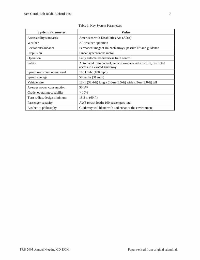
Table 1. Key System Parameters
System Parameter Value
Accessibility standards Americans with Disabilities Act (ADA)
Weather All-weather operation
Levitation/Guidance Permanent magnet Halbach arrays; passive lift and guidance
Propulsion Linear synchronous motor
Operation Fully automated driverless train control
Safety Automated train control, vehicle wraparound structure, restricted access to elevated guideway
Speed, maximum operational 160 km/hr (100 mph)
Speed, average 50 km/hr (31 mph)
Vehicle size 12-m (39.4-ft) long x 2.6-m (8.5-ft) wide x 3-m (9.8-ft) tall
Average power consumption 50 kW
Grade, operating capability > 10%
Turn radius, design minimum 18.3 m (60 ft)
Passenger capacity AW3 (crush load): 100 passengers total
Aesthetics philosophy Guideway will blend with and enhance the environment
TRB 2003 Annual Meeting CD-ROM Paper revised from original submittal.

Sam Gurol, Bob Baldi, Richard Post 8
Table 2. Urban Maglev Team Members
Urban Maglev Team Member Responsibility
General Atomics System Integration and Magnetics
Carnegie Mellon University Magnetics
Hall Industries Vehicles
Mackin Engineering Co. Guideway Design and EIS
Pennsylvania Department of Transportation Transportation Studies
PJ Dick Guideway Construction
Sargent Electric Co. Power Distribution
Union Switch & Signal Communication and Controls
Western Pennsylvania Maglev Development Corp. Commercialization
Booz-Allen Hamilton Transportation Studies
Lawrence Livermore National Laboratory Magnetics
TRB 2003 Annual Meeting CD-ROM Paper revised from original submittal.

Sam Gurol, Bob Baldi, Richard Post 9
Table 3. Key System Requirements
Key Requirements
Speed, Max 160 km/hr Jerk, Max 2.5 m/s3
Throughput 12000/hr/direction Noise Level Inside < 67 dBA
Acceleration, Max 1.6 m/s2 DC Magnetic Field in Car < 5 Gauss
Curve Radius, Min 18.3 m Availability > 99.99 %
Grade, Max 10% Ride Quality ISO 2631 (1987)
TRB 2003 Annual Meeting CD-ROM Paper revised from original submittal.

Sam Gurol, Bob Baldi, Richard Post 10
Table 4. Vehicle Design Parameters
Design Parameters
Vehicle Weight Empty
9500 kg
Full 16500 kg
Vehicle Dimension Length
12 m
Height 3 m Width 2.6 m
No. of Vehicles per Train 4
Speed, max 160 km/hr
TRB 2003 Annual Meeting CD-ROM Paper revised from original submittal.

Sam Gurol, Bob Baldi, Richard Post 11
Table 5. Comparison of Litz Track Performance with Laminated Track
0.5 m litz track 0.5 m lam. track 0.3 m lam. track
Levitated weight, kg 600. 1000. 1800. L/D at 20 m/sec 6.0 12.5 15.0
Transition Speed, m/sec 6.4 2.8 2.8
TRB 2003 Annual Meeting CD-ROM Paper revised from original submittal.
Sam Gurol, Bob Baldi, Richard Post 12
System StudiesSystem Studies
Base Technology
Development
Base Technology
Development
Route Specific RequirementsRoute Specific Requirements
0 6 12
• World-Wide Maglev Systems
• Requirements Definition
• Levitation Subsystem Selection
• Subsystem Analyses• Risk Reduction Test Hardware• Dynamic Test Facility
• Preliminary System Engineering• Tight Turn Capability Assessment• Switch Design
• Conceptual Design and Analysis• Engineering and Construction Schedule• ROM Cost Estimate• Commercialization Plan
Full-Scale System Concept
18Months Figure 1. The General Atomics Team Plan
TRB 2003 Annual Meeting CD-ROM Paper revised from original submittal.
Sam Gurol, Bob Baldi, Richard Post 13
Construction Tolerances
Light VehiclesChallenging Terrain
All-Weather Operation
Large Air Gap Maglev System
EDSLevitation
LSMPropulsion
Expandability / Versatility
+
High Speed Potential
Figure 2. Design Flow Logic Used in Selecting Key Levitation and Propulsion Subsystems
TRB 2003 Annual Meeting CD-ROM Paper revised from original submittal.
Sam Gurol, Bob Baldi, Richard Post 14
d 1
d 2
y
-h
h
x y 0 2d tr
Direction of Motion
Magnetization Vectors
Figure 3. Guideway/Vehicle Chassis and Double Halbach Array Levitation Magnets
Track Double Halbach Array
Levitation Magnets
Propulsion Magnets
LSM Cables
Secondary Suspension (Air Bags)
Chassis Structure Guidance
Laminations
TRB 2003 Annual Meeting CD-ROM Paper revised from original submittal.
Sam Gurol, Bob Baldi, Richard Post 15
0 5 10 15 2015
20
25
30
velocity [m/s]
gap
g1 [
mm
]
Figure 4. Gap vs. Velocity
_____ Empty
_____ Full
TRB 2003 Annual Meeting CD-ROM Paper revised from original submittal.
Sam Gurol, Bob Baldi, Richard Post 16
0 5 10 15 200
10
20
30
40
50
fullempty
Velocity [m/s]
Dra
g fo
rce
[kN
]
Figure 5. Magnetic Drag vs. Velocity Including the Effect of Wind Resistance and Eddy Currents
TRB 2003 Annual Meeting CD-ROM Paper revised from original submittal.
Sam Gurol, Bob Baldi, Richard Post 17
0.1 1 10 1001 .10 5
1 .10 4
1 .10 3
0.01
0.1
1
ISO 1 - 4 min. LimitISO 1 hr LimitISO 2 hr LimitISO 8 hr Limit1/3 Octave with Pad-averaging
Frequency, Hz
Acc
eler
atio
n in
1/3
Oct
ave
Ban
ds, g
Figure 6. Predicted RMS Acceleration of the UML Passenger Compartment in 1/3 Octave Bands
TRB 2003 Annual Meeting CD-ROM Paper revised from original submittal.
Sam Gurol, Bob Baldi, Richard Post 18
Figure 7. Simple Three-Phase LSM Winding and Propulsion/Guidance Magnets
3-Phase LSM Cables Iron Laminations
Iron Laminations
3-Phase LSM Cables
Propulsion / Guidance Magnets
TRB 2003 Annual Meeting CD-ROM Paper revised from original submittal.
Sam Gurol, Bob Baldi, Richard Post 19
Figure 8. Vehicle Design is Modular with a Passive Secondary Suspension
TRB 2003 Annual Meeting CD-ROM Paper revised from original submittal.
Sam Gurol, Bob Baldi, Richard Post 20
LSM Windings
Halbach Array Magnets
Load Cell
Figure 9. Static LSM Test Set-Up Recreates Full-Scale Propulsion Parameters
TRB 2003 Annual Meeting CD-ROM Paper revised from original submittal.
Sam Gurol, Bob Baldi, Richard Post 21
Levitation Magnets
Moving Track
Figure 10. Sub-Scale Laminated Track Testing.
TRB 2003 Annual Meeting CD-ROM Paper revised from original submittal.
Sam Gurol, Bob Baldi, Richard Post 22
Figure 11. Relative lift force as a function of phase shift at 10 m/sec.
TRB 2003 Annual Meeting CD-ROM Paper revised from original submittal.
Sam Gurol, Bob Baldi, Richard Post 23
Figure12. Magnetic Levitation Test Wheel
TRB 2003 Annual Meeting CD-ROM Paper revised from original submittal.
Sam Gurol, Bob Baldi, Richard Post 24
0 5 10 15 20 25500
0
500
1000
1500
2000
2500
MeasuredPredicted
velocity [m/s]
drag
for
ce [
N]
0 5 10 15 20 250
2000
4000
6000
8000
1 .104
MeasuredPredicted
velocity [m/s]
lift f
orce
[N
]
Figure 13. Lift and Drag Forces for a Fixed Gap on Test Wheel
TRB 2003 Annual Meeting CD-ROM Paper revised from original submittal.