general atomics urban maglev: moving towards … urban...general atomics urban maglev: moving...
TRANSCRIPT
1
General Atomics Urban Maglev:
Moving Towards Demonstration
Presented by Dr. Sam Gurol
General Atomics – Electromagnetic Systems
Director, Maglev Systems
San Diego, CA
October 12, 2007

2
“Staircase” Towards Deployment
Concept
Development(Completed)
Concept
Development(Completed)
Prototype
Component Testing
(In Process)
Prototype
Component Testing
(In Process)
Demonstration
System
Demonstration
System
Prototype
ComponentDesign
(Completed)
Prototype
ComponentDesign
(Completed)
Concept
Development(Completed)
Concept
Development(Completed)
Prototype
Component Testing
(In Process)
Production
Development -Test Track
(In Process)
Demonstration
System
Demonstration
System
DeploymentDeploymentDeploymentDeployment
Prototype
ComponentDesign
(Completed)
Prototype
Development
(Completed)
3
What’s New?
• Simple, passive permanent magnets.
• EDS levitation requires no gap control.
• Fail-safe in event of power failure.
• Large air gap operation will result in cheaper construction.
• No shielding required in passenger compartment.
• Driverless operation with safety-certified Automatic Train Protection (ATP) system.
• No high voltage equipment on vehicle, no third rail for power pick-up.
• Enables tight turns, steep grades, quiet.
• Major system cost savings (avoids tunneling, which costs from $125M to $250M per km).
• O&M costs are expected to be very low, reducing life-cycle costs.

4
Body Module
Chassis
Vehicle and Guideway
• 2 Chassis Car Length – 13 m• Car Width – 2.6 m• Car Height – 3 m
Fiber-Reinforced “Hybrid Girder”

5
Other Vehicle Configuration Options
Chassis units can be connected to produce longer passenger vehicle
Chassis units can be connected to produce 2-TEU cargo conveyor
6
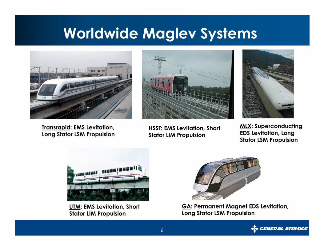
Worldwide Maglev Systems
Transrapid: EMS Levitation, Long Stator LSM Propulsion
HSST: EMS Levitation, Short Stator LIM Propulsion
MLX: Superconducting EDS Levitation, Long Stator LSM Propulsion
UTM: EMS Levitation, Short Stator LIM Propulsion
GA: Permanent Magnet EDS Levitation, Long Stator LSM Propulsion

7
Test Track Uses Full-Scale “Building Blocks”
Levitation Track LSM
Windings

8
Control and Electrical Room
Inverter Cabinet Interior ViewData Acquisition Vehicle Control Panel

9
• Permanent magnets – Double Halbach array
• Maximizes parallel B component, minimizes I
• Track - transposed conductors
• Magnetic field cancellation on back side
• Reaction currents in track produce levitation
Direction of Travel
Principle of “Passive” EDS Levitation
d1
d2
y
-h
h
x
y0 2dtr
Upper Halbach Array
Lower Halbach Array
Track

10
Magnetic Levitation and Drag Forces
Full vehicle
Empty vehicle
Full vehicle
0 5 10 15 200
10
20
30
40
50
full
empty
Velocity [m/s]
Dra
g f
orc
e [k
N]
Empty Vehicle
0 5 10 15 2015
20
25
30
Speed (m/s)
Air G
ap
(m
m)
Speed (m/s)
0 5 10 15 200
10
20
40
30
50
Dra
g F
orc
e (
kN
)
Full Vehicle
Empty Vehicle
Full Vehicle
•Peak power is required for a few seconds during vehicle lift-off.
•The sudden drop in magnetic drag force and changing air gap result in the uniqueness of the LSM thrust control requirements.
•Peak power capability is ~ 80 kN for a full vehicle.

11
Overall Propulsion Control System Architecture
LSMVector Controller LSM Vehicle
Speed Controller
ThrustApplied Current
Speed / Position
Current Command
SpeedCommand
•Inner current loop (τ τ τ τ ~ 30 ms) adjusts propulsion current.
•Outer speed loop (ττττ ~ 500 ms) provides speed control.
•No control system is required for levitation.

12
Section 2 through 7
155.0
160.0
165.0
170.0
mm West
East
The Levitation and Propulsion Systems Operate Well Despite Inaccurate Track Construction
13
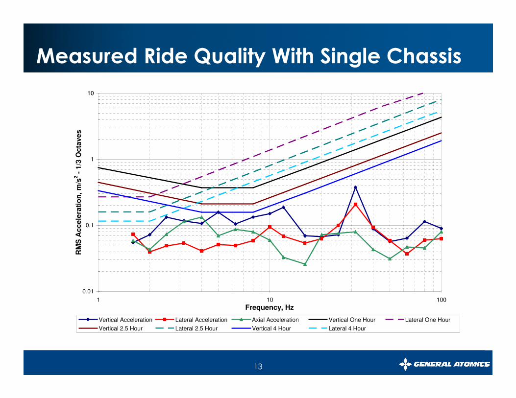
Measured Ride Quality With Single Chassis
0.01
0.1
1
10
1 10 100
Frequency, Hz
RM
S A
cce
lera
tio
n,
m/s
2 -
1/3
Octa
ve
s
Vertical Acceleration Lateral Acceleration Axial Acceleration Vertical One Hour Lateral One Hour
Vertical 2.5 Hour Lateral 2.5 Hour Vertical 4 Hour Lateral 4 Hour

14
Cruise Power Projections Based on Test Data
50 kW4.3 kW (9%)2.25kN x 20m/s = 45 kWDemonstration system with block switches
250 kW210 kW (84%)5kN x 8m/s = 40kWSingle chassis (present system)
Total Losses
I2R Cable Losses
Drag PowerSystem Being Tested
2000
1500
1000
500
0
-500
Kilo
watts
5 10 15 20 25 30 35
Time (Seconds)
Acceleration Cruise Speed
Braking
2000
1500
1000
500
0
-500
Kilo
watts
5 10 15 20 25 30 35
Time (Seconds)
Acceleration Cruise Speed
Braking

15
ATP Speed Profile Test Data
ATP Speed Profile
85.0, 0.0
83.0, 2.0
72.2, 5.5
50.8, 7.534.2, 7.5
12.8, 5.5
2.0, 2.0
0
1
2
3
4
5
6
7
8
0 10 20 30 40 50 60 70 80 90 100
Distance Traveled (m)
Velo
city (m
/s)
1. Protect test system from an over-speed condition.
2. Collect information for demonstration system ATP design
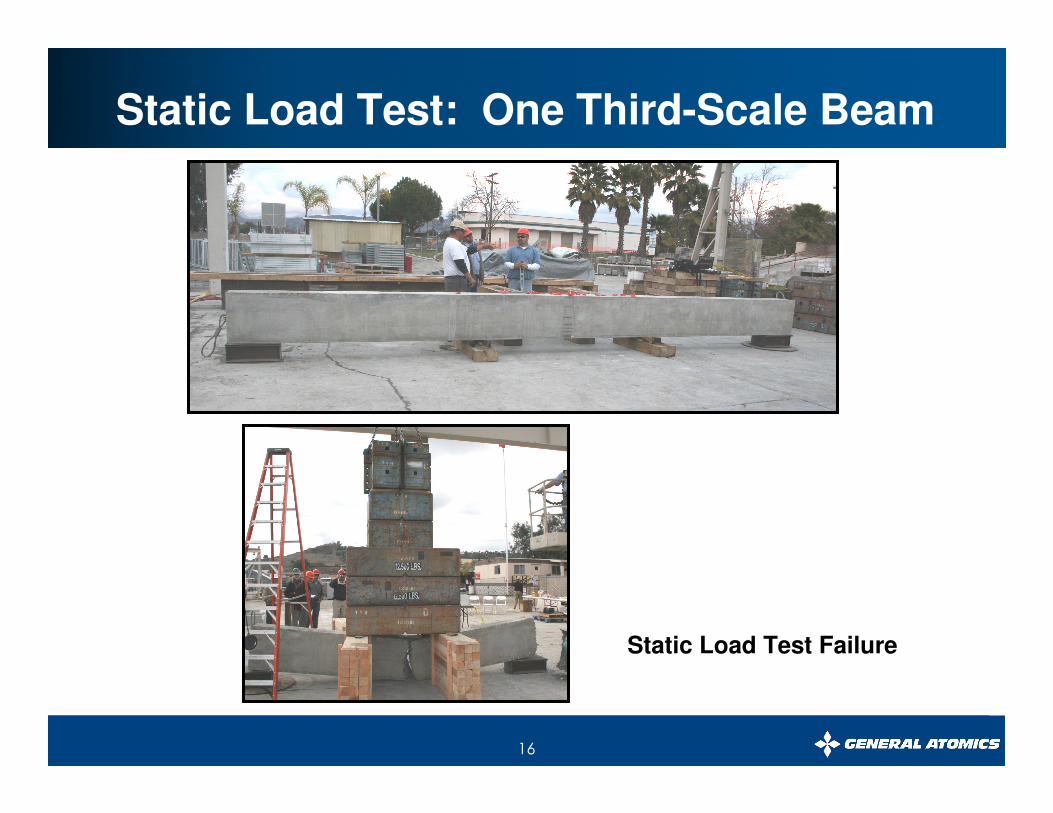
16
Static Load Test: One Third-Scale Beam
Static Load Test Failure

17
Plans for Test Track Extension
• Extend test track 90 meters
• Manufacture 4 hybrid girders
• Higher speeds (55 km/h)

18
Vehicle Body Design and Fabrication
Standard Body
Modules
Nose Body Module
Door Opening
Vehicle Body Modules
Aluminum AlloyTruss Work
Body Modules
Body Modules and Backbone Structure
Air-Conditioning Fairing
Roof Fairing and Air-Conditioning Unit
Lexan Windows
Installed
Window Installation
Fairing
Chassis
Vehicle Body
Body Installed on Chassis Unit

19
California University of Pennsylvania Demonstration System
• Demonstrates 1 mile 7% Grade and All-Weather Operation
• Serves a University Transportation Need
James Adamson Stadium
Student HousingOverlooking the Bluff
Convocation Center Site

20
World’s First Cargo Maglev Move – June 2006
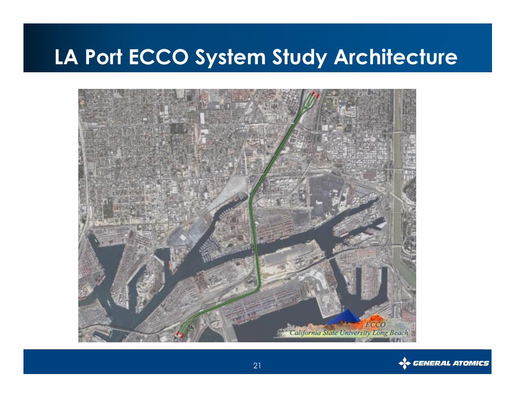
21
LA Port ECCO System Study Architecture

22
UCSD Maglev System Connects Sorrento Valley Transit Station (The Coaster) with Pepper Canyon LRT Station (SD Trolley)

23
2000 2001 2002 2003 2004 2005 2006 2007 2008 2009
Roadmap Leading to Demonstration
• Preliminary Engineering
• Prototype Component Testing
• Test Track Construction
•CUP Preliminary Engineering
• Preliminary Testing
• Extended Testing
• Pre-Construction Planning for CUP,
Update Engineering
• Fabricate Second Chassis
•Design Vehicle Car Body
• Systems Optimization
•CUP Detail Engineering &
Construction
MAGLEV 2008 Conference

24
The 20The 20The 20The 20th th th th International Conference on Magnetically Levitated International Conference on Magnetically Levitated International Conference on Magnetically Levitated International Conference on Magnetically Levitated Systems and Linear DrivesSystems and Linear DrivesSystems and Linear DrivesSystems and Linear Drives
December 15December 15December 15December 15----18, 200818, 200818, 200818, 2008San Diego, California, USASan Diego, California, USASan Diego, California, USASan Diego, California, USA
MAGLEV'2008

25
� Advantages are simple, passive, fail-safe levitation, and large air-gap operation.
� No high voltage equipment on vehicles.
� About one-half the weight per unit length of existing maglev systems.
� Significant potential for capital and O&M cost savings.
� Test track in San Diego operating for over 3 years is validating system performance, costs and schedules.
� Maglev 2008 conference will be opportunity to showcase new technology.
Conclusions
Contact: [email protected]