solar air conditioner€¦ · owner's manual sc air conditioners thank you for selecting solar...
TRANSCRIPT
OWNER'S MANUALSC AIR CONDITIONERS
Thank you for selecting Solar Cool air conditioner. Please read this manual carefully before operation and keep it for further reference.
S o l a r A i r C o n d i t i o n e r
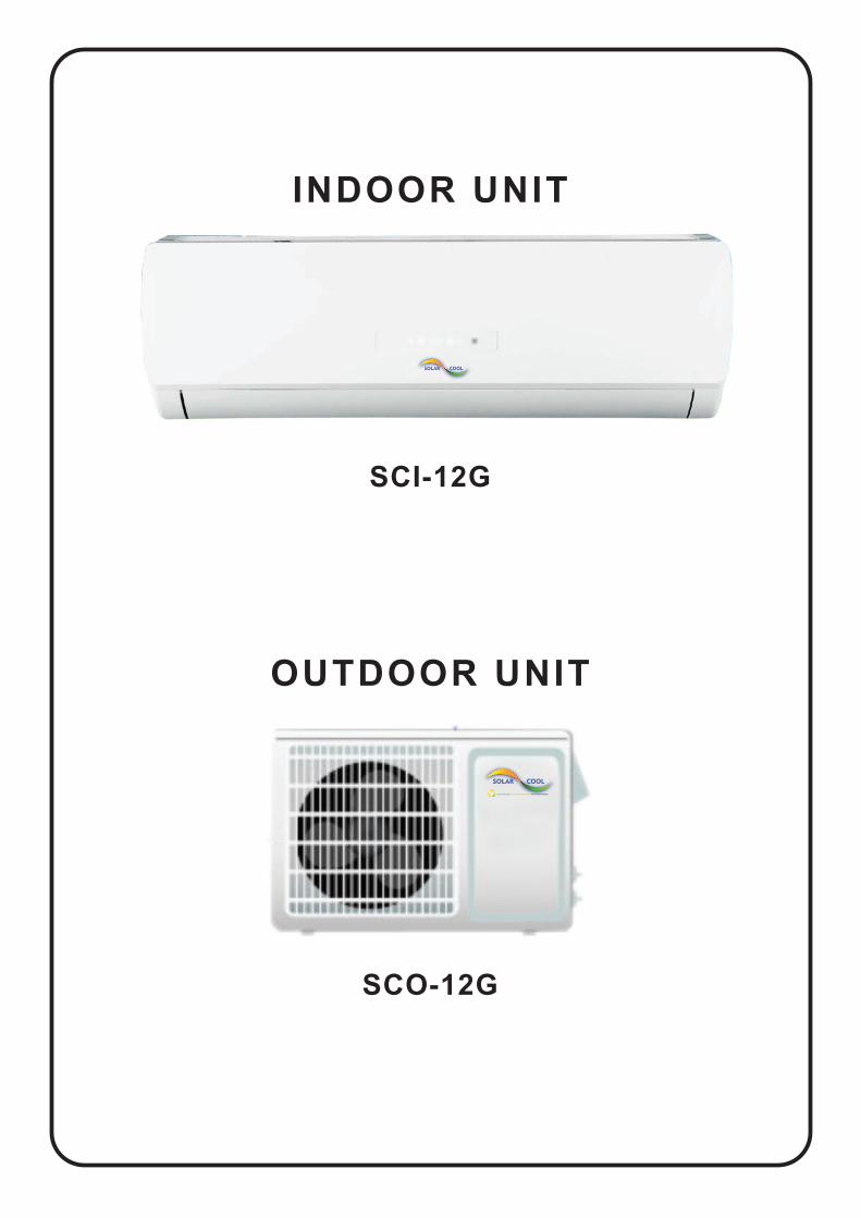
SCO-12G
OUTDOOR UNIT
SCI-12G
INDOOR UNIT
CONTENTS
This symbol stands for the itemsshould be forbidden.
This symbol stands for the items should be followed
■ ..................................1
■
■ ................................14
■ ....................................17
■ ..........................22
■ ...................................23
■ ..................................25
■ ..................33
■ ...............34
■
■ ................................20
■ ....................................15
Operation and maintenanceNotices for operation
Notices for use ......................................3
Names and functions of each part .........................5
■Operation of wireless remote control ........................6
Clean and care
Troubleshooting
Installation serviceNotices for installation
Installation dimension diagram
Install indoor unit
Install outdoor unit
Check after installation and test operation
Emergency operation
Installation and Maintenance of Healthy Filter
Do not dispose this product as unsorted municipal waste. Collection of such waste separately for special treatment is necessary.
The products in this manual may be different with the real one, according to different models, some models have displayer and some models without displayer, the position and shape of the displayer please refer to the real one.
This appliance is not intended for use by persons (including children) with reducedphysiced, sensory or mental capabilities or lack of experience and knowledge, unless they have been given supervision or instruction concerning use of the appliance by a person reponsible for thei safety.Children should be supervised to ensure that they do not play with the appliance.
Image shown in this operating instruction manual here is indicative only. Actual product you receive may differ!
■ ..................................27Install PV-module
★
★
★
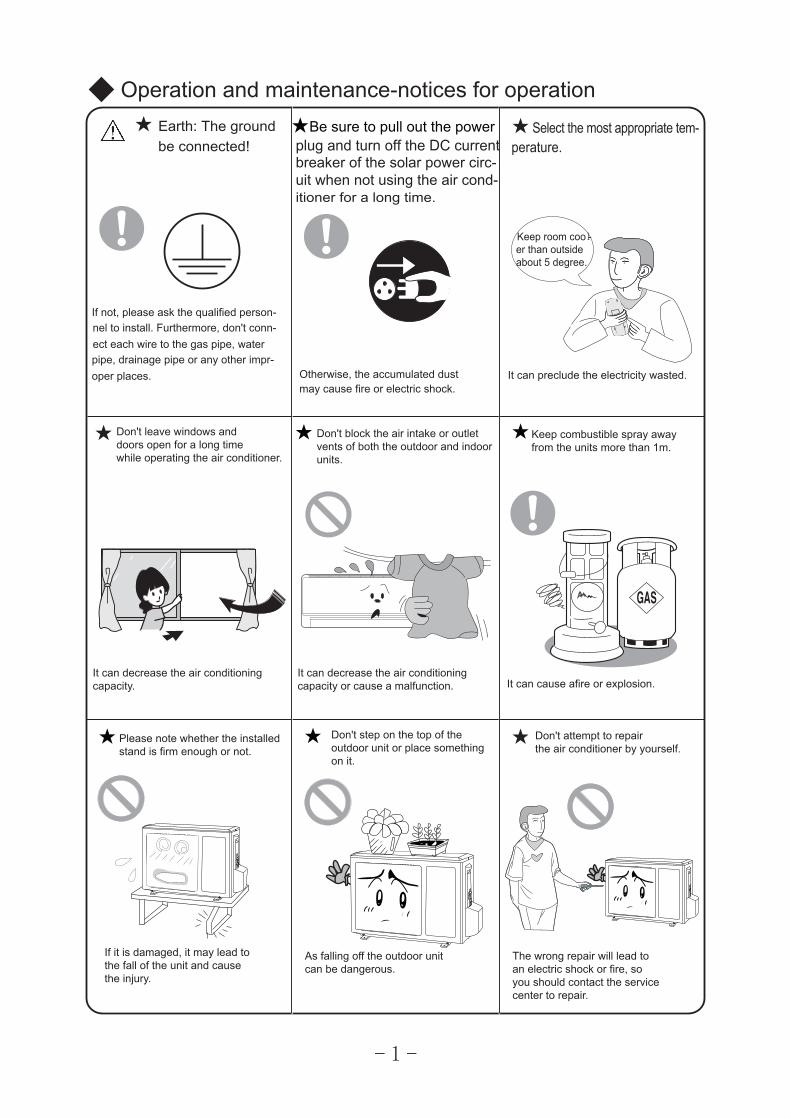
Operation and maintenance-notices for operation
1
★ ★Be sure to pull out the power
★
★ ★
★
Earth: The groundbe connected!
If not, please ask the qualified person-nel to install. Furthermore, don't conn-ect each wire to the gas pipe, water pipe, drainage pipe or any other impr-oper places.
plug and turn off the DC current
itioner for a long time.
Otherwise, the accumulated dust may cause fire or electric shock.
Select the most appropriate tem-perature.
Keep room cool-er than outsideabout 5 degree.
It can preclude the electricity wasted.
Don't leave windows and doors open for a long time while operating the air conditioner.
It can decrease the air conditioningcapacity.
Don't block the air intake or outletvents of both the outdoor and indoorunits.
It can decrease the air conditioningcapacity or cause a malfunction.
Keep combustible spray awayfrom the units more than 1m.
It can cause afire or explosion.
If it is damaged, it may lead tothe fall of the unit and causethe injury.
Please note whether the installedstand is firm enough or not.
Don't step on the top of theoutdoor unit or place somethingon it.
As falling off the outdoor unitcan be dangerous.
Don't attempt to repairthe air conditioner by yourself.
The wrong repair will lead toan electric shock or fire, soyou should contact the servicecenter to repair.
breaker of the solar power circ-uit when not using the air cond-
2
★★
★
★
★
★
★ ★
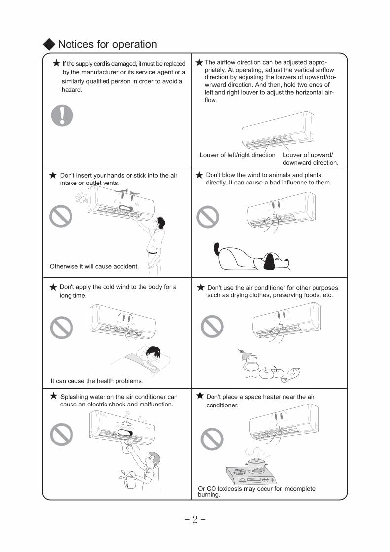
Notices for operationIf the supply cord is damaged, it must be replaced by the manufacturer or its service agent or a similarly qualified person in order to avoid a hazard.
The airflow direction can be adjusted appro-priately. At operating, adjust the vertical airflowdirection by adjusting the louvers of upward/do-wnward direction. And then, hold two ends ofleft and right louver to adjust the horizontal air-flow.
Louver of left/right direction Louver of upward/downward direction.
Don't insert your hands or stick into the airintake or outlet vents.
Otherwise it will cause accident.
Don't blow the wind to animals and plantsdirectly. It can cause a bad influence to them.
Don't apply the cold wind to the body for along time.
It can cause the health problems.
Don't use the air conditioner for other purposes,such as drying clothes, preserving foods, etc.
Splashing water on the air conditioner cancause an electric shock and malfunction.
Don't place a space heater near the air conditioner.
Or CO toxicosis may occur for imcompleteburning.
*
*
*
*
*
*
Notices for use
Working principle and special functions for cooling
Principle:
Anti-freezing function:
Working principle and special functions for heating
Principle:
Defrosting:
Air conditioner absorbs heat in the room and transmit to outdoor and discharged, so thatindoor ambient temperature decreased, its cooling capacity will increase or decrease byoutdoor ambient temperature.
If the unit is running in COOL mode and in low temperature, there will be frost formed onthe heat exchanger, when indoor heat exchanger temperature decreased below 32 , theindoor unit microcomputer will stop compressor running and protect the unit.
Air conditioner absorbs heat from outdoor and transmits to indoor, in this way to increaseroom temperature. This is the heat pump heating principle, its heating capacity will bereduced due to outdoor temperature decrease.If outdoor temperature becomes very low, please operate with other heating equipments.
When outdoor temperature is low but high humidity, after a long while running, frost willform on outdoor unit, that will effect the heating effect, at this time, the auto defrosting function will act, the heat running will stop for 8-10mins.During the auto defrosting, the fan motors of indoor unit and outdoor unit will stop.During the defrosting, the indoor indicator flashes, the outdoor unit may emit vapor.This is due to the defrosting, it isn't malfunction.After defrosting finished,the heating will recover automatically.
3
Fº
4
Notices for use
Anti-cool wind function:In "Heat" mode, under the following three kinds of state, if indoor heat exchanger doesn't arrive at certain temp., indoor fan will not act, in order to prevent cool wind blowing(within2 mins):
1. Heating starts. 2.After Auto Defrost finished. 3.Heating under the low temperature.
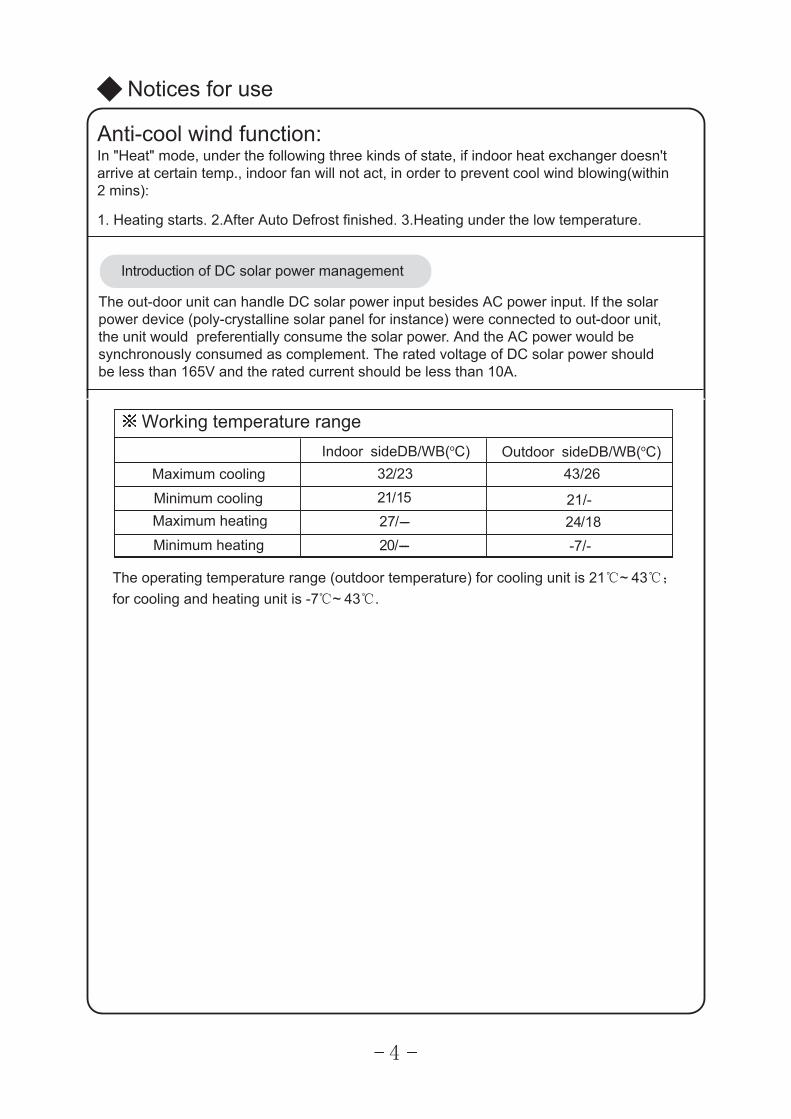
The operating temperature range (outdoor temperature) for cooling unit is 21℃~ 43℃;
for cooling and heating unit is -7℃~ 43℃.
Working temperature range
Maximum cooling
Minimum coolingMaximum heating
Minimum heating
Indoor sideDB/WB(oC) Outdoor sideDB/WB(oC)32/2321/1527/---20/---
43/26
21/- 24/18 -7/-
Introduction of DC solar power management
The out-door unit can handle DC solar power input besides AC power input. If the solar power device (poly-crystalline solar panel for instance) were connected to out-door unit, the unit would preferentially consume the solar power. And the AC power would be synchronously consumed as complement. The rated voltage of DC solar power should be less than 165V and the rated current should be less than 10A.
⑹
⑸
⑵
⑻
⑼
⑽
⑷
⑺
⑶
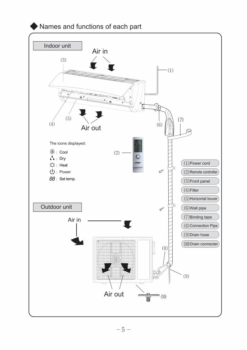
⑴Power cord
Remote controller
Front panel
Filter
Horizontal louver
Wall pipe
Binding tape
Connection Pipe
Drain hose
Drain connecter
Names and functions of each part
⑻
⑼
⑵
Indoor unit
⑹⑺
:Cool:Dry
:Heat
:Set temp.
:Power
The icons displayed:
5
Air out
Outdoor unit
Air in
⑽
Air in⑶
⑴
⑷⑸
Air out
6
Name and function of wireless remote controller
ON/OFF button
Remote controller
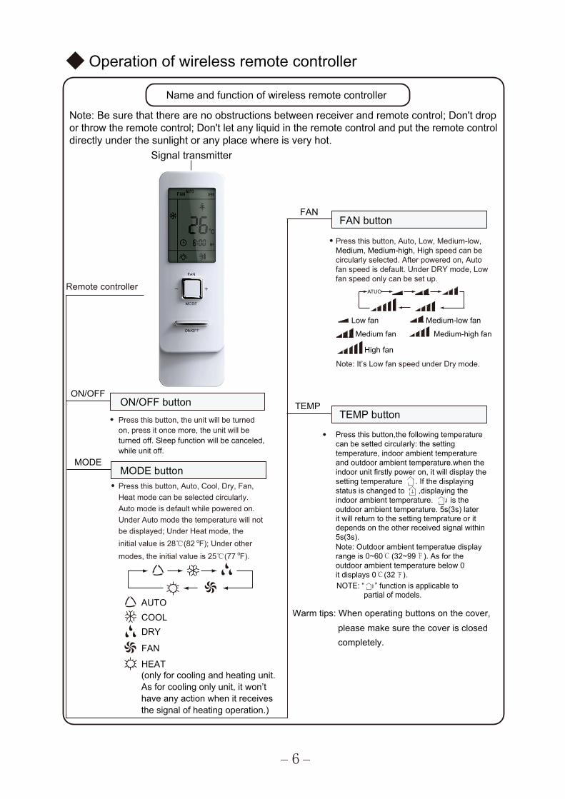
Signal transmitter
Note: Be sure that there are no obstructions between receiver and remote control; Don't drop or throw the remote control; Don't let any liquid in the remote control and put the remote control directly under the sunlight or any place where is very hot.
Operation of wireless remote controller
● Press this button, the unit will be turned on, press it once more, the unit will be turned off. Sleep function will be canceled, while unit off.
TEMP buttonTEMP
ON/OFF
AUTOCOOLDRY
FAN
(only for cooling and heating unit.As for cooling only unit, it won’thave any action when it receivesthe signal of heating operation.)
● Press this button, Auto, Cool, Dry, Fan,Heat mode can be selected circularly.
MODE buttonMODE
Auto mode is default while powered on. Under Auto mode the temperature will notbe displayed; Under Heat mode, the
HEAT
initial value is 28℃(82 F); Under other o
modes, the initial value is 25℃(77 F).o
● Press this button, Auto, Low, Medium-low,Medium, Medium-high, High speed can becircularly selected. After powered on, Autofan speed is default. Under DRY mode, Low fan speed only can be set up.
FAN buttonFAN
Medium fan
Low fan
High fan
Medium-low fan
Medium-high fan
Note: It’s Low fan speed under Dry mode.
ATUO
● Press this button,the following temperature can be setted circularly: the setting temperature, indoor ambient temperature and outdoor ambient temperature.when the indoor unit firstly power on, it will display the setting temperature . If the displaying status is changed to ,displaying theindoor ambient temperature. is the outdoor ambient temperature. 5s(3s) laterit will return to the setting temprature or it depends on the other received signal within5s(3s).Note: Outdoor ambient temperatue display range is 0~60℃ (32~99℉). As for the outdoor ambient temperature below 0it displays 0℃(32℉).
Warm tips: When operating buttons on the cover, please make sure the cover is closed completely.
NOTE: “ ” function is applicable to partial of models.
7
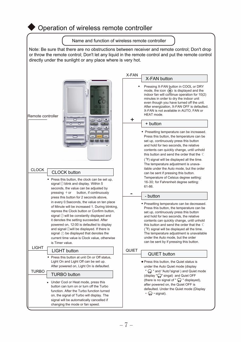
Remote controller
Note: Be sure that there are no obstructions between receiver and remote control; Don't drop or throw the remote control; Don't let any liquid in the remote control and put the remote control directly under the sunlight or any place where is very hot.
● Press this button, the clock can be set up,signal blink and display. Within 5
CLOCK buttonCLOCK
seconds, the value can be adjusted by pressing or button, if continuouslypress this button for 2 seconds above,
Operation of wireless remote controller
and signal will be displayed. If there is
current time value is Clock value, otherwise
in every 0.5seconds, the value on ten placeof Minute will be increased 1. During blinking,repress the Clock button or Confirm button,signal will be constantly displayed andit denotes the setting succeeded. Afterpowered on, 12:00 is defaulted to display
is Timer value.
signal be displayed that denotes the
●
●
Press this button at unit On or Off status,Light On and Light Off can be set up.
LIGHT buttonLIGHT
After powered on, Light On is defaulted.
X-FAN buttonX-FAN
● Pressing X-FAN button in COOL or DRY mode, the icon is displayed and the indoor fan will continue operation for 10(2)minutes in order to dry the indoor unit even though you have turned off the unit.After energization, X-FAN OFF is defaulted. X-FAN is not available in AUTO, FAN orHEAT mode.
Under Cool or Heat mode, press thisbutton can turn on or turn off the Turbo
TURBO buttonTURBO
function. After the Turbo function turned on, the signal of Turbo will display. Thesignal will be automatically cancelled if changing the mode or fan speed.
● Presetting temperature can be increased. Press this button, the temperature can be
+ button
set up, continuously press this button and hold for two seconds, the relative contents can quickly change, until unholdthis button and send the order that the ℃( oF) signal will be displayed all the time.The temperature adjustment is unava-ilable under the Auto mode, but the order can be sent if pressing this button.Temperature of Celsius degree setting:16-30; for Fahrenheit degree setting:61-86.
● Presetting temperature can be decreased.Press this button, the temperature can be
- button
set up, continuously press this button and hold for two seconds, the relative contents can quickly change, until unholdthis button and send the order that the ℃( oF) signal will be displayed all the time.The temperature adjustment is unavailableunder the Auto mode, but the ordercan be sent by if pressing this button.
QUIETQUIET button
●Press this button, the Quiet status isunder the Auto Quiet mode (display" " and “Auto”signal ) and Quiet mode
(display " " singal) and Quiet OFF(there is no signal of " " displayed),after powered on, the Quiet OFF isdefaulted. Under the Quiet mode (Display
Name and function of wireless remote controller
+
-
signal). " "
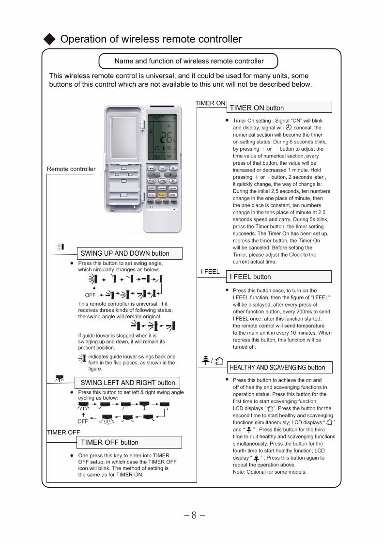
Remote controller
buttons of this control which are not available to this unit will not be described below.This wireless remote control is universal, and it could be used for many units, some
Operation of wireless remote controller
● One press this key to enter into TIMEROFF setup, in which case the TIMER OFF icon will blink. The method of setting isthe same as for TIMER ON.
TIMER OFFTIMER OFF button
8
SWING LEFT AND RIGHT button
● Press this button to set swing angle,which circularly changes as below:
OFFThis remote controller is universal. If itreceives threes kinds of following status,the swing angle will remain original.
If guide louver is stopped when it isswinging up and down, it will remain itspresent position.
indicates guide louver swings back andforth in the five places, as shown in thefigure.
SWING UP AND DOWN button
● Press this button to set left & right swing angle cycling as below:
OFF
TIMER ONTIMER ON button
●
I FEEL button
●
●
I FEEL
Timer On setting : Signal “ON” will blinkand display, signal will conceal, thenumerical section will become the timeron setting status. During 5 seconds blink,by pressing + or - button to adjust thetime value of numerical section, everypress of that button, the value will beincreased or decreased 1 minute. Holdpressing+ or -button, 2 seconds later ,it quickly change, the way of change is:During the initial 2.5 seconds, ten numberschange in the one place of minute, thenthe one place is constant, ten numberschange in the tens place of minute at 2.5seconds speed and carry. During 5s blink,press the Timer button, the timer settingsucceeds. The Timer On has been set up,repress the timer button, the Timer Onwill be canceled. Before setting theTimer, please adjust the Clock to thecurrent actual time.
HEALTHY AND SCAVENGING button/
Name and function of wireless remote controller
Press this button once, to turn on theI FEEL function, then the figure of "I FEEL"will be displayed, after every press ofother function button, every 200ms to sendI FEEL once, after this function started,the remote control will send temperatureto the main un it in every 10 minutes. Whenrepress this button, this function will beturned off.
Press this button to achieve the on andoff of healthy and scavenging functions inoperation status. Press this button for thefirst time to start scavenging function;LCD displays “ ”. Press the button for thesecond time to start healthy and scavengingfunctions simultaneously; LCD displays “ ”and “ ” . Press this button for the thirdtime to quit healthy and scavenging functionssimultaneously. Press the button for thefourth time to start healthy function; LCDdisplay “ ” . Press this button again torepeat the operation above.Note: Optional for some models.
9
●
●
Operation of wireless remote controller
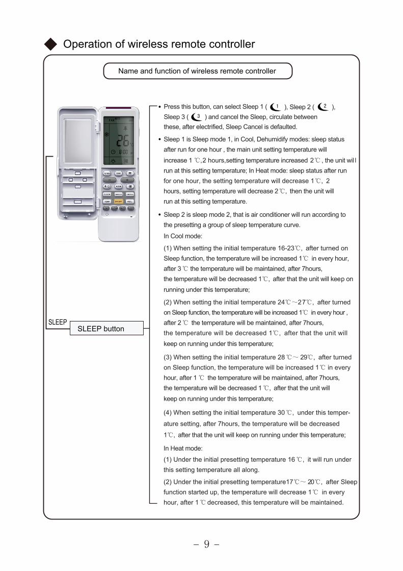
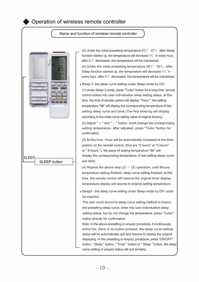
SLEEP buttonSLEEP
(1peelStcelesnac,nottubsihtsserP ), Sleep 2 ( ),Sleep 3 ( ) and cancel the Sleep, circulate betweenthese, after electrified, Sleep Cancel is defaulted.
Sleep 1 is Sleep mode 1, in Cool, Dehumidify modes: sleep statusafter run for one hour , the main unit setting temperature will
increase 1 ℃,2 hours,setting temperature increased 2℃ , the unit wil lrun at this setting temperature; In Heat mode: sleep status after runfor one hour, the setting temperature will decrease 1℃, 2hours, setting temperature will decrease 2℃, then the unit willrun at this setting temperature.
● Sleep 2 is sleep mode 2, that is air conditioner will run according tothe presetting a group of sleep temperature curve.
In Cool mode:
(1) When setting the initial temperature 16-23℃, after turned onSleep function, the temperature will be increased 1℃ in every hour,after 3℃ the temperature will be maintained, after 7hours,the temperature will be decreased 1℃, after that the unit will keep onrunning under this temperature;
(2) When setting the initial temperature 24℃~27℃, after turnedon Sleep function, the temperature will be increased 1℃ in every hour ,after 2℃ the temperature will be maintained, after 7hours,the temperature will be decreased 1℃, after that the unit willkeep on running under this temperature;
(3) When setting the initial temperature 28℃~ 29℃, after turned on Sleep function, the temperature will be increased 1℃ in everyhour, after 1 ℃ the temperature will be maintained, after 7hours,the temperature will be decreased 1℃, after that the unit willkeep on running under this temperature;
(4) When setting the initial temperature 30℃, under this temper-
ature setting, after 7hours, the temperature will be decreased
1℃, after that the unit will keep on running under this temperature;
In Heat mode:
(1) Under the initial presetting temperature 16℃, it will run under this setting temperature all along.
(2) Under the initial presetting temperature17℃~ 20℃, after Sleep function started up, the temperature will decrease 1℃ in everyhour, after 1℃ .deniatniameblliwerutarepmetsiht,desaerced
Name and function of wireless remote controller
10
+
Operation of wireless remote controller
SLEEP buttonSLEEP
(3) Under the initial presetting temperature 21℃~27℃, after Sleepfunction started up, the temperature will decrease 1℃ in every hour,after 2℃ decreased, this temperature will be maintained.
(4) Under the initial presetting temperature 28℃~30℃, afterSleep function started up, the temperature will decrease 1℃ inevery hour, after 3℃ decreased, this temperature will be maintained.
Sleep 3- the sleep curve setting under Sleep mode by DIY:
(1) Under Sleep 3 mode, press "Turbo" button for a long time, remotecontrol enters into user individuation sleep setting status, at thistime, the time of remote control will display "1hour ", the setting
(2) Adjust " " and " " button, could change the corresponding setting temperature, after adjusted, press "Trubo "button forconfirmation;
(3) At this time, 1hour will be automatically increased at the timer
postion on the remote control, (that are "2 hours" or "3 hours"
(4) Repeat the above step (2) ~ (3) operation, until 8hours
temperature setting finished, sleep curve setting finished, at this
time, the remote control will resume the original timer display;
temperature "88" will display the corresponding temperature of last
setting sleep curve and blink (The first entering will display
according to the initial curve setting value of original factory);
or " 8 hours "), the place of setting temperature "88" willdisplay the corresponding temperature of last setting sleep curve
and blink;
temperature display will resume to original setting temperature.
●
● Sleep3 - the sleep curve setting under Sleep mode by DIY could
be inquired:
The user could accord to sleep curve setting method to inquire
the presetting sleep curve, enter into user individuation sleep
setting status, but do not change the temperature, press "Turbo"
button directly for confirmation.Note: In the above presetting or enquiry procedure, if continuouslywithin10s, there is no button pressed, the sleep curve settingstatus will be automatically quit and resume to display the originaldisplaying. In the presetting or enquiry procedure, press "ON/OFF"button, " Mode " button, " Timer " button or " Sleep " button, the sleepcurve setting or enquiry status will quit similarly.
-
Name and function of wireless remote controller
11
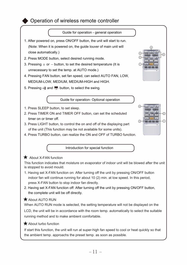
timer on or timer off.
Guide for operation - general operation
Operation of wireless remote controller
★This function indicates that moisture on evaporator of indoor unit will be blowed after the unit
About X-FAN function
is stopped to avoid mould.1. Having set X-FAN function on: After turning off the unit by pressing ON/OFF button
indoor fan will continue running for about 10 (2) min. at low speed. In this period,press X-FAN button to stop indoor fan directly.
2. Having set X-FAN function off: After turning off the unit by pressing ON/OFF button, the complete unit will be off directly.
Introduction for special function
When AUTO RUN mode is selected, the setting temperature will not be displayed on the
LCD, the unit will be in accordance with the room temp. automatically to select the suitablerunning method and to make ambient comfortable.
About turbo function
If start this function, the unit will run at super-high fan speed to cool or heat quickly so thatthe ambient temp. approachs the preset temp. as soon as possible.
★
★
About AUTO RUN
1. Press SLEEP button, to set sleep.2. Press TIMER ON and TIMER OFF button, can set the scheduled
3. Press LIGHT button, to control the on and off of the displaying part of the unit (This function may be not available for some units).
4. Press TURBO button, can realize the ON and OFF of TURBO function.
close automatically.)
5. Pressing and button, to select the swing.
4. Pressing FAN button, set fan speed, can select AUTO FAN, LOW,
MEDIUM-LOW, MEDIUM, MEDIUM-HIGH and HIGH.
unnecessary to set the temp. at AUTO mode.)
2. Press MODE button, select desired running mode.
(Note: When it is powered on, the guide louver of main unit will
1. After powered on, press ON/OFF button, the unit will start to run.
Guide for operation- Optional operation
3. Pressing or button, to set the desired temperature (It is
5
1
2
3
4
1
2
3
4
12
Press buttons simultaneously to lock or unlock the keyboard. If the remote controllerandis locked, the iconflicker for three times. If the keyboard is unlocked, the mark will disappear.
1. Press swing + and - button continuously more than 2s, the main unit will swing backand forth from + to - , and then loosen the button, the unit will stop swinging and presentposition of guide louver will be kept immediately.
2. Under swing + and - mode, when the status is switched from off to , if press thisbutton again 2s later, status will switch to off status directly; if press this button againwithin 2s, the change of swing status will also depend on the circulation sequence stated above.
★About swing + and -
★
★
★
1. Press swing left and right button continuously more than 2s, the main unit will swing backand forth from left to right, and then loosen the button, the unit will stop swinging and presentposition of guide louver will be kept immediately.
2. Under swing left and right mode, when the status is switched from off to , if press thisbutton again 2s later, status will switch to off status directly; if press this button againwithin 2s, the change of swing status will also depend on the circulation sequence stated above.
★About swing left and right
About lock
will be displayed on it, in which case, press any button, the mark will
Operation of wireless remote controller
About switch between Fahrenheit and CentigradeUnder status of unit off, press MODE and - buttons simultaneously to switch ℃ and ℉.
★
About Quiet function★
About Sleep functionUnder the Fan and Auto mode, the Sleep function cannot be set up, under Dehumidifymode, only Sleep 1 can be selected. Select and enter into any kind of Sleep mode, the
★
Quiet function will be attached and stared, different Quiet status could be optional and turned off.
Press “TEMP” and “CLOCK” simultaneously in COOL mode to start energy-saving function.Nixie tube on the remote controller displays “SE”. Repeat the operation to quit the function.
Press “TEMP” and “CLOCK” simultaneously in HEAT mode to start 8℃ Heating Function.Nixie tube on the remote controller displays “ ” and a selected temperature of “ 8℃”
(46 if Fahrenheit is adopted). Repeat the operation to quit the function.
Combination of " TEMP" and "CLOCK" buttons: About 8
Combination of " TEMP" and "CLOCK" buttons: About Energy-saving Function
℃ Heating Function
℉
When quiet function is selected:1. Under cooling mode: indoor fan operates at notch 4 speed. 10 minutes later or when indoor ambient temperature≤28℃, indoor fan will operate at notch 2 speed or quiet mode according to the comparison between indoor ambinet temperature and set temperature. 2. Under heating mode: indoor fan operates at notch 3 speed or quiet mode according to the comparison between indoor ambient temperature and set temperature.3. Under dry, fan mode: indoor fan operates at quiet mode.4. Under auto mode: the indoor fan operates at the auto quiet mode according to actual cooling, heating or fan mode.
●
●
●
●
●
●
●
Operation of wireless remote controller
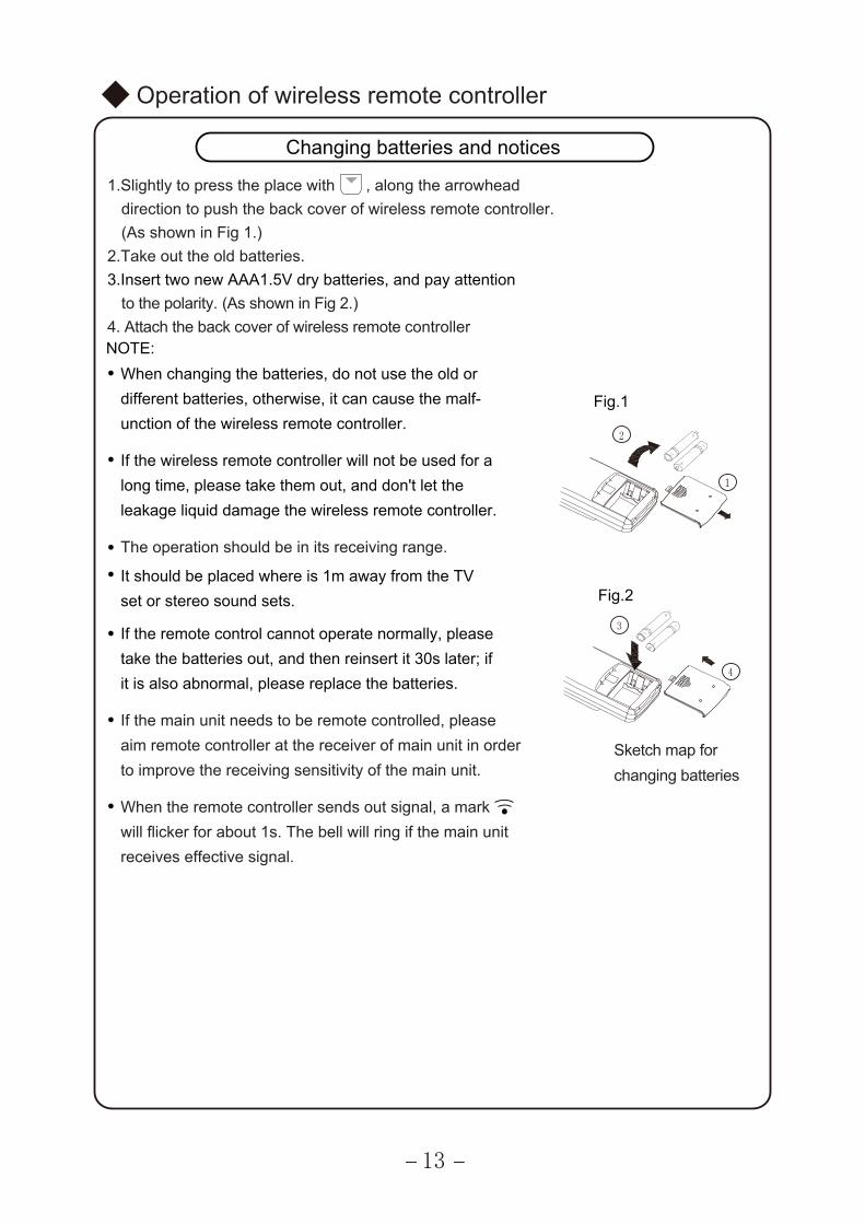
Changing batteries and notices
1.Slightly to press the place with , along the arrowhead direction to push the back cover of wireless remote controller.(As shown in Fig 1.)
2.Take out the old batteries. 3.Insert two new AAA1.5V dry batteries, and pay attention
NOTE:When changing the batteries, do not use the old ordifferent batteries, otherwise, it can cause the malf-unction of the wireless remote controller.
If the wireless remote controller will not be used for along time, please take them out, and don't let theleakage liquid damage the wireless remote controller.
It should be placed where is 1m away from the TVset or stereo sound sets.
The operation should be in its receiving range.
If the remote control cannot operate normally, pleasetake the batteries out, and then reinsert it 30s later; if
If the main unit needs to be remote controlled, please aim remote controller at the receiver of main unit in orderto improve the receiving sensitivity of the main unit.
When the remote controller sends out signal, a markwill flicker for about 1s. The bell will ring if the main unit receives effective signal.
it is also abnormal, please replace the batteries.
13
to the polarity. (As shown in Fig 2.)4. Attach the back cover of wireless remote controller
Fig.1
Fig.2
Sketch map forchanging batteries
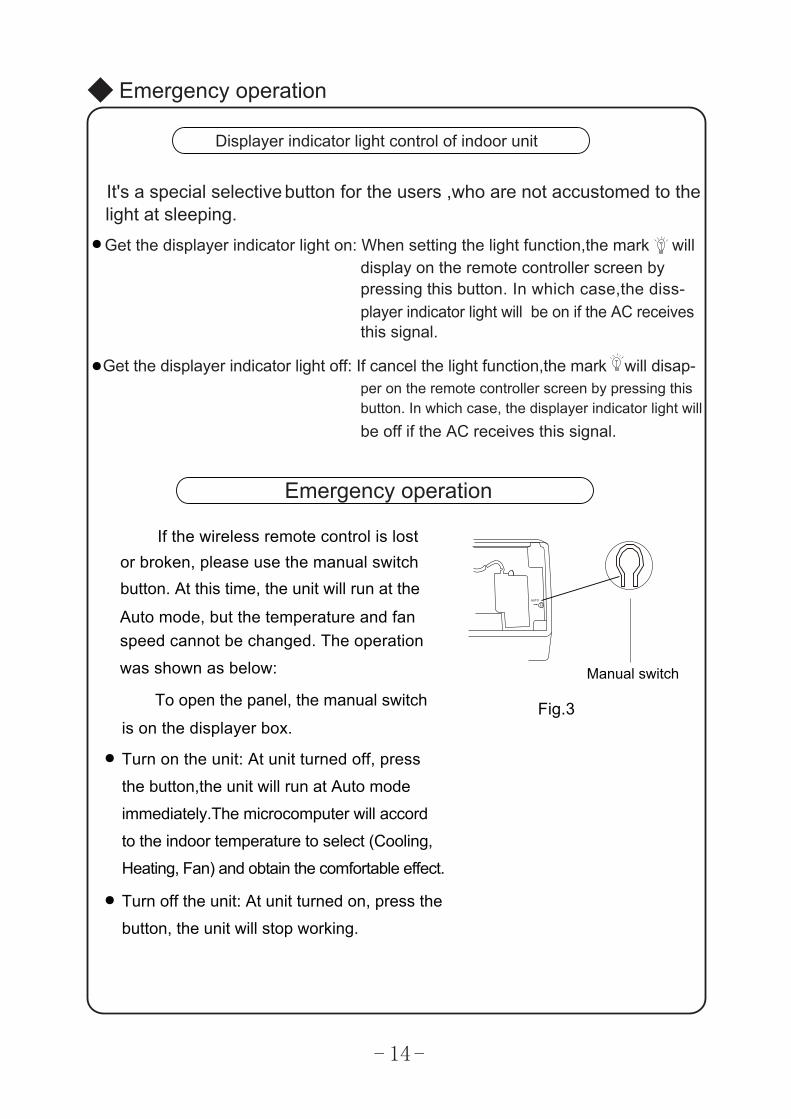
If the wireless remote control is lost or broken, please use the manual switch
Auto mode, but the temperature and fan
button. At this time, the unit will run at the
To open the panel, the manual switch
is on the displayer box.
It's a special selective button for the users ,who are not accustomed to the light at sleeping.Get the displayer indicator light on: When setting the light function,the mark will
pressing this button. In which case,the diss-player indicator light will be on if the AC receives
Get the displayer indicator light off: If cancel the light function,the mark will disap-per on the remote controller screen by pressing this button. In which case, the displayer indicator light willbe off if the AC receives this signal.
Displayer indicator light control of indoor unit
●
●
display on the remote controller screen by
this signal.
Emergency operation
Emergency operation
speed cannot be changed. The operation
was shown as below:
Turn on the unit: At unit turned off, press
the button,the unit will run at Auto mode
immediately.The microcomputer will accord
●
to the indoor temperature to select (Cooling,
Heating, Fan) and obtain the comfortable effect.
Turn off the unit: At unit turned on, press the
button, the unit will stop working.
●
Manual switch
Fig.3
14
℃
●
●
●
℃
② Clean the air filter
③
①
(a)
(b)
Clean and care
Caution
Turn power off and pull out the power plug before cleaning air conditioner, or it may cause electricshock.
Never sprinkle water on the indoor unit and the outdoor unit for cleaning because it can cause anelectric shock.
Volatile liquid (e.g. thinner or gasoline) will damage the air conditioner. (So wipe the units with adry soft cloth, or a cloth slightly moistened with water or cleanser.)
Clean the front panel
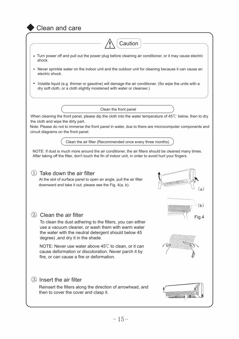
Clean the air filter (Recommended once every three months)
NOTE: If dust is much more around the air conditioner, the air filters should be cleaned many times.After taking off the filter, don't touch the fin of indoor unit, in order to avoid hurt your fingers.
Take down the air filterAt the slot of surface panel to open an angle, pull the air filterdownward and take it out, please see the Fig. 4(a, b).
To clean the dust adhering to the filters, you can eitheruse a vacuum cleaner, or wash them with warm waterthe water with the neutral detergent should below 45degree) ,and dry it in the shade.
NOTE: Never use water above 45 to clean, or it cancause deformation or discoloration. Never parch it byfire, or can cause a fire or deformation.
Insert the air filterReinsert the filters along the direction of arrowhead, andthen to cover the cover and clasp it.
Fig.4
When cleaning the front panel, please dip the cloth into the water temperature of 45 below, then to drythe cloth and wipe the dirty part.Note: Please do not to immerse the front panel in water, due to there are microcomputer components andcircuit diagrams on the front panel.
15
① Be sure that nothing obstructs the air outlet and intake vents.
②
③ Check that whether the batteries of air conditioner are changed or not.
④ Check that whether the installation stand of the outdoor unit is damaged or not. If damaged, please contact the dealer.
①
②
③
④
⑤
Clean and care
Check before use
Check that whether ground wire is properly connected or not.
Maintain after use
Turn main power off.
Clean the filter and indoor and outdoor units' bodies.
Clear dust and obstructions from the outdoor unit.
Repaint the rubiginous place on the outdoor unit to prevent it from spreading.
Adopt the special shield to cover the outdoor unit, avoid the rain water, dust enter intothe unit and get rust.
16
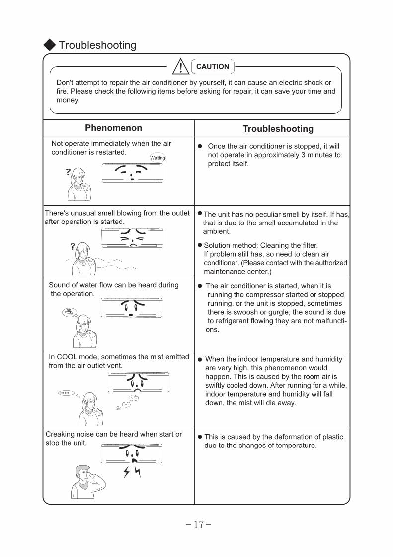
Once the air conditioner is stopped, it willnot operate in approximately 3 minutes toprotect itself.
●
●
●
●
●
●
Troubleshooting
CAUTION
Don't attempt to repair the air conditioner by yourself, it can cause an electric shock orfire. Please check the following items before asking for repair, it can save your time andmoney.
Phenomenon TroubleshootingNot operate immediately when the airconditioner is restarted.
There's unusual smell blowing from the outletafter operation is started.
The unit has no peculiar smell by itself. If has,that is due to the smell accumulated in the ambient.
Solution method: Cleaning the filter.If problem still has, so need to clean air conditioner. (Please contact with the authorized maintenance center.)
Sound of water flow can be heard during the operation.
The air conditioner is started, when it is running the compressor started or stopped running, or the unit is stopped, sometimes there is swoosh or gurgle, the sound is due to refrigerant flowing they are not malfuncti-ons.
In COOL mode, sometimes the mist emittedfrom the air outlet vent.
When the indoor temperature and humidity are very high, this phenomenon would happen. This is caused by the room air is swiftly cooled down. After running for a while, indoor temperature and humidity will fall down, the mist will die away.
Creaking noise can be heard when start or stop the unit.
This is caused by the deformation of plastic due to the changes of temperature.
Waiting
17
●
●
●
●
●
●
●
●
●
●
●
●
●
●
●
●
●
●
●
●
●
●
Troubleshooting
Phenomenon Troubleshooting
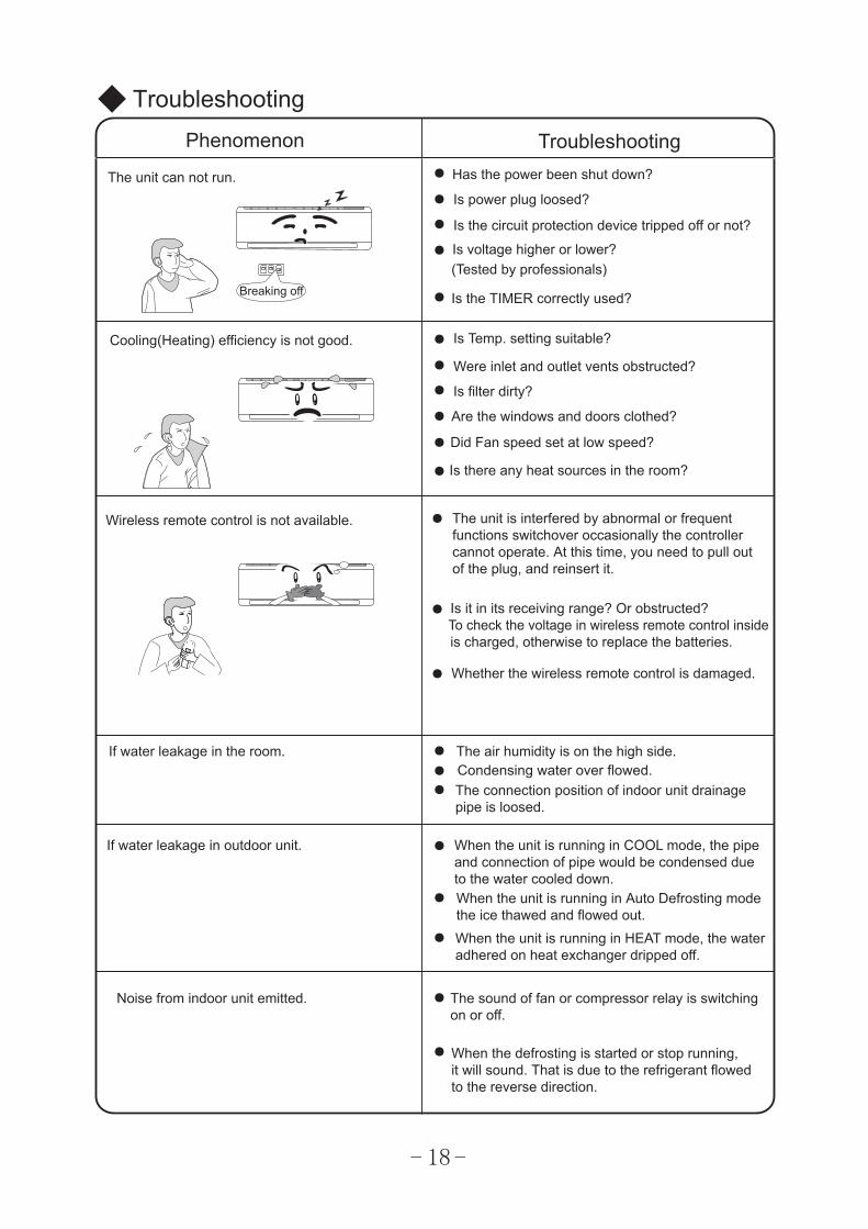
The unit can not run. Has the power been shut down?
Is power plug loosed?
Is the circuit protection device tripped off or not?
Is voltage higher or lower?(Tested by professionals)
Is the TIMER correctly used?
Cooling(Heating) efficiency is not good. Is Temp. setting suitable?
Were inlet and outlet vents obstructed?
Is filter dirty?
Are the windows and doors clothed?
Did Fan speed set at low speed?
Is there any heat sources in the room?
Wireless remote control is not available. The unit is interfered by abnormal or frequentfunctions switchover occasionally the controllercannot operate. At this time, you need to pull outof the plug, and reinsert it.
Is it in its receiving range? Or obstructed?To check the voltage in wireless remote control insideis charged, otherwise to replace the batteries.
Whether the wireless remote control is damaged.
If water leakage in the room. The air humidity is on the high side.Condensing water over flowed.The connection position of indoor unit drainagepipe is loosed.
If water leakage in outdoor unit. When the unit is running in COOL mode, the pipe and connection of pipe would be condensed dueto the water cooled down.When the unit is running in Auto Defrosting mode the ice thawed and flowed out.When the unit is running in HEAT mode, the water adhered on heat exchanger dripped off.
Noise from indoor unit emitted. The sound of fan or compressor relay is switchingon or off.
When the defrosting is started or stop running,it will sound. That is due to the refrigerant flowedto the reverse direction.
Breaking off
18
●
●
●
●
TroubleshootingPhenomenon Troubleshooting
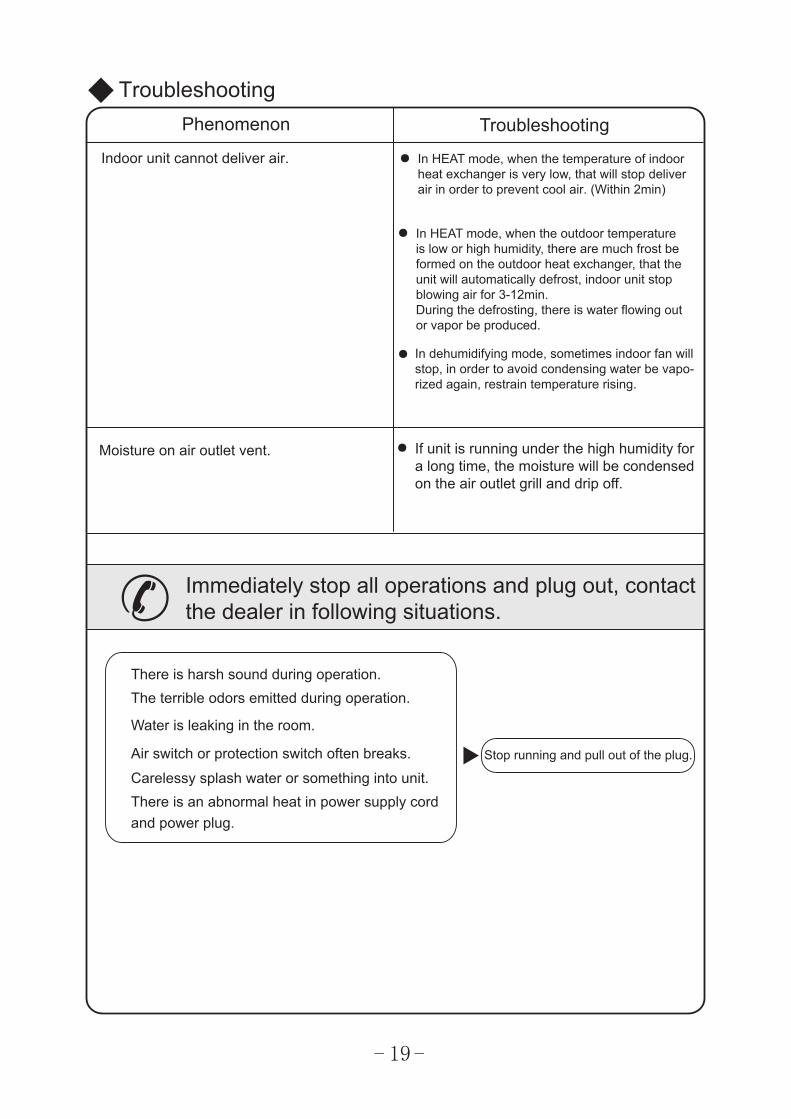
Indoor unit cannot deliver air.
Moisture on air outlet vent. If unit is running under the high humidity fora long time, the moisture will be condensedon the air outlet grill and drip off.
Immediately stop all operations and plug out, contactthe dealer in following situations.
There is harsh sound during operation.The terrible odors emitted during operation.
Water is leaking in the room.
Air switch or protection switch often breaks.
Carelessy splash water or something into unit.There is an abnormal heat in power supply cordand power plug.
Stop running and pull out of the plug.
In HEAT mode, when the temperature of indoorheat exchanger is very low, that will stop deliverair in order to prevent cool air. (Within 2min)
In HEAT mode, when the outdoor temperatureis low or high humidity, there are much frost be formed on the outdoor heat exchanger, that the unit will automatically defrost, indoor unit stop blowing air for 3-12min.During the defrosting, there is water flowing out or vapor be produced.
In dehumidifying mode, sometimes indoor fan willstop, in order to avoid condensing water be vapo-rized again, restrain temperature rising.
19
1.
2.Select a position where the condensing water can be easily drained out, and the placeis easily connected for outdoor unit.
4.Can select the place where is strong enough to withstand the full weight and vibration ofthe unit. And will not increase the noise.
5.
6.7.8.Make sure that the indoor unit installation should accord with installation dimension
diagram requirements.
1.Select a location from which noise and outflow air emitted by unit will not inconvenience neighbors, animals, plants.2.Select a location where there should be sufficient ventilation.3.Select a location where there should be no obstructions cover the inlet and outlet vent.4.The location should be able to withstand the full weight and vibration of the outdoor unit and permit safe installation.5.Select a dry place, but do not expose under the direct sunlight or strong wind.6.
3.Select a location where the children can not reach.
1.The unit installation work must be done by qualified personnel according to the localrules and this manual.
2.Before installation, please contact with local authorized maintenance center, if unit isnot installed by the authorized maintenance center, the malfunction may not solved,due to discommodious contacts.
3.When removing the unit to the other place, please firstly contact with the authorizedMaintenance Center in the local area.
●
●
7.
8.9.
●
●
●
●
Notices for installation
Important Notices
Basic Requirements For Installation Position
Install in the following place may cause malfunction. If it is unavoidable contact with service center please:
Place where strong heat sources, vapors, flammable gas or volatile object are emitted.Place where high-frequency waves are generated by radio equipment, welders and medical equipment.Place where a lot of salinities such as coast exists.Place where the oil (machine oil) is contained in the air.Place where a sulfured gas such as the hot spring zones is generated.Other place with special circumstance.
Indoor Unit Installation Position Selection
The air inlet and outlet vent should be far from the obstruction, make sure that the aircan be blown through the whole room.
Be sure to leave enough space to allow access for routine maintenance. The height of theinstalled location should be 250cm or more from the floor.Select a place about 1m or more away from TVset or any other electric appliances.Select a place where the filter can be easily taken out.
Outdoor Unit Installation Position Selection
Make sure that the outdoor unit installation dimension should accord with installation dimension diagram, convenient for maintenance, repair.The height difference of connecting the tubing within 5m, the length of connecting thetubing within 10m.Select a place where it is out of reach for the children.Select a place where will not block the passage and do not influence the city appearance.
.Do not use the unit in the immediate surroundings of a laundry a bath a shower or a swimming pool.
9
20
Notices for installation
Safety Requirements For Electric Appliances
Earthing requirements
Note:Make sure that the Live wire or Zero line as well as the earth wire in the family power socket can not be wrong connected, there should be reliable and no short circuit in the diagram.
wrong connection may cause fire.
♂
♂
4. The min. distance from the unit and combustive surface is 1.5m.
1. The power supply should be used the rated voltage and AC exclusive circuit,the power cable diameter should be satisfied.
2. Don't drag the power cable emphatically.3.
① ② ③
④
1. Air conditioner is type I electric appliance, thus please do conduct reliable earthingmeasure.
2. The yellow-green two-color wire in air conditioner is earthing wire and cannot be usedfor other propose. It cannot be cut off and be fix it by screw, otherwise it would causeelectric shock.
3. The earth resistance should accord to the National Criterion.4. The user power must offer the reliable earthing terminal. Please don't connect the
earthing wire with the following place:
Tap water pipe. Gas pipe. Contamination pipe.
Other places that professional personnel consider them unreliable.
5. The appliance shall be installed in accordance with national wiring regulations.
An all-pole disconnection switch having a contact separation of at least 3mm in all poles should be connected in fixed wiring.
It should be reliably earthed, and it should be connected to the special earth device,the installation work should be operated by the professional. The air switch must have the functions of magnetic tripping and heat tripping, in order to protect the short circuit and overloading.
6.
5. The model and rating values for fuses according the silk print on fuse cover or related PCB board.
21
7. Poly-crystalline solar panel is strongly recommended as solar power device. The rated voltage of DC solar power should be less than 165V and the rated current should be less than 10A. Take the poly-crystalline solar panel of 200W (open-circuit voltage:33V, short-circuit current:8.12A)for instance, the maximum number in one series of of panels is 5, and the connention method should be series connection.
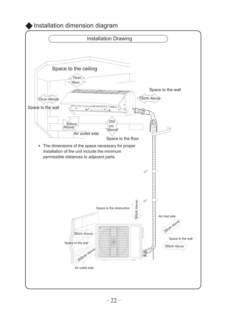
Installation dimension diagram
Installation Drawing
Space to the ceiling
Space to the wall
Space to the wall
Air outlet sideSpace to the floor
AboveAbove
15cm Above
Abov
22
The dimensions of the space necessary for proper installation of the unit include the minimum permissible distances to adjacent parts.
●
Space to the wall
Space to the obstruction
Air outlet side
Space to the wall
Air inlet side
15cm Above
15cm
250cm300cm
50cm
Abo
ve
50cm Above
30cm Above
30cm Above
200cm Above
23
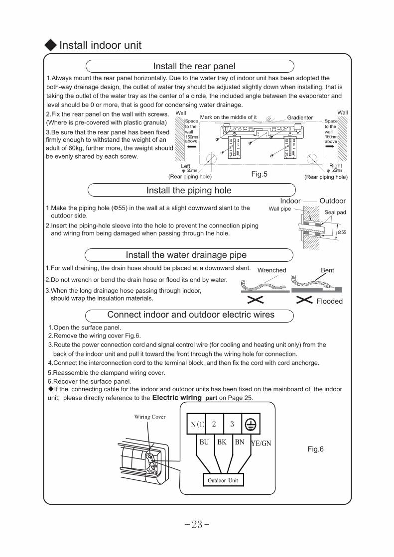
Install indoor unit
mm0 5 1
mm5 5 φ mm5 5 φ
mm0 5 1
Ø 5 5
Install the rear panel 1.Always mount the rear panel horizontally. Due to the water tray of indoor unit has been adopted theboth-way drainage design, the outlet of water tray should be adjusted slightly down when installing, that is taking the outlet of the water tray as the center of a circle, the included angle between the evaporator and level should be 0 or more, that is good for condensing water drainage. 2.Fix the rear panel on the wall with screws.(Where is pre-covered with plastic granula) 3.Be sure that the rear panel has been fixedfirmly enough to withstand the weight of an adult of 60kg, further more, the weight should be evenly shared by each screw.
Install the piping hole
1.Make the piping hole (Ф55) in the wall at a slight downward slant to the outdoor side.2.Insert the piping-hole sleeve into the hole to prevent the connection piping and wiring from being damaged when passing through the hole.
Install the water drainage pipe 1.For well draining, the drain hose should be placed at a downward slant.
2.Do not wrench or bend the drain hose or flood its end by water.
3.When the long drainage hose passing through indoor, should wrap the insulation materials.
Wrenched Bent
Flooded
Indoor OutdoorWall pipe
Seal pad
Fig.5
Wall WallMark on the middle of it Gradienter
Left Right
(Rear piping hole) (Rear piping hole)
Spaceto thewall
above
Spaceto thewall
above
Fig.6
Connect indoor and outdoor electric wires 1.Open the surface panel.2.Remove the wiring cover Fig.6.3.Route the power connection cord and signal control wire (for cooling and heating unit only) from the
4.Connect the interconnection cord to the terminal block, and then fix the cord with cord anchorge.5.Reassemble the clampand wiring cover.
back of the indoor unit and pull it toward the front through the wiring hole for connection.
6.Recover the surface panel.
N(1) 2 3
YE/GNBU BK BN
Outdoor Unit
◆If the connecting cable for the indoor and outdoor units has been fixed on the mainboard of the indoor unit, please directly reference to the Electric wiring part on Page 25.
24
●
●
● After tighten the screw, slight pull the wire and confirm whether is it firm or not.● ● The cover plate must be fixed, and tighten the connection wire, if it is poor installed, that
Install indoor unit
NOTE:When connecting the electric wire if the wire length is not enough, please contact withthe authorized service shop to buy a exclusive electric wire that is long enough and thejoint on the wire are not allowed.
The electric wiring must be correctly connected, wrong connection may cause spare partsmalfunction.Tighten the terminal screw in order to prevent loose.
If the earth wire is wrong connection, that may cause electric shock.
the dust, moisture may enter in or the connection terminal will be affected by outside force,and will cause fire or electric shock.
右后
4.
2.
3.
●
1.
⑴ ⑵
1.2.
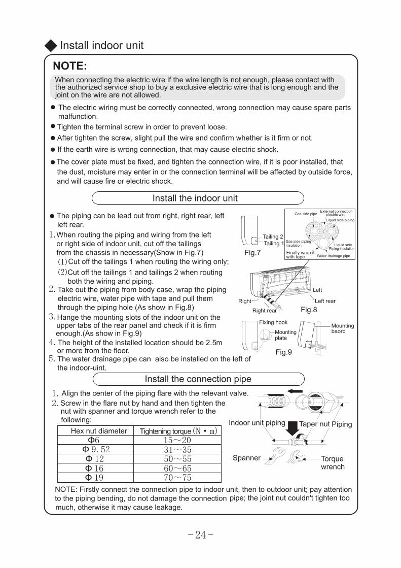
Install the indoor unit
The piping can be lead out from right, right rear, leftleft rear.When routing the piping and wiring from the leftor right side of indoor unit, cut off the tailingsfrom the chassis in necessary(Show in Fig.7)
Cut off the tailings 1 when routing the wiring only;Cut off the tailings 1 and tailings 2 when routingboth the wiring and piping.
Take out the piping from body case, wrap the pipingelectric wire, water pipe with tape and pull themthrough the piping hole (As show in Fig.8)Hange the mounting slots of the indoor unit on theupper tabs of the rear panel and check if it is firmenough.(As show in Fig.9)The height of the installed location should be 2. mor more from the floor.
Install the connection pipeAlign the center of the piping flare with the relevant valve.Screw in the flare nut by hand and then tighten thenut with spanner and torque wrench refer to thefollowing:
NOTE: Firstly connect the connection pipe to indoor unit, then to outdoor unit; pay attentionto the piping bending, do not damage the connection pipe; the joint nut couldn't tighten toomuch, otherwise it may cause leakage.
Spanner Torquewrench
PipingTaper nutIndoor unit piping
Fig.9
Mountingplate
Fixing hook Mountingbaord
Right
Right rear Fig.8Left rear
Left
Fig.7Tailing 1Tailing 2
Finally wrap itwith tape
Gas side pipinginsulation
Water drainage pipe
Liquid sidePiping insulation
Gas side pipeExternal connection
electric wireLiquid side piping
(N·m)Ф6
Ф 9.52Ф 12
31~3515~20
50~55Ф 16 60~65Ф 19 70~75
Hex nut diameter Tightening torque
5
5.The water drainage pipe can also be installed on the left of the indoor-uint.
Handle
25
●
●
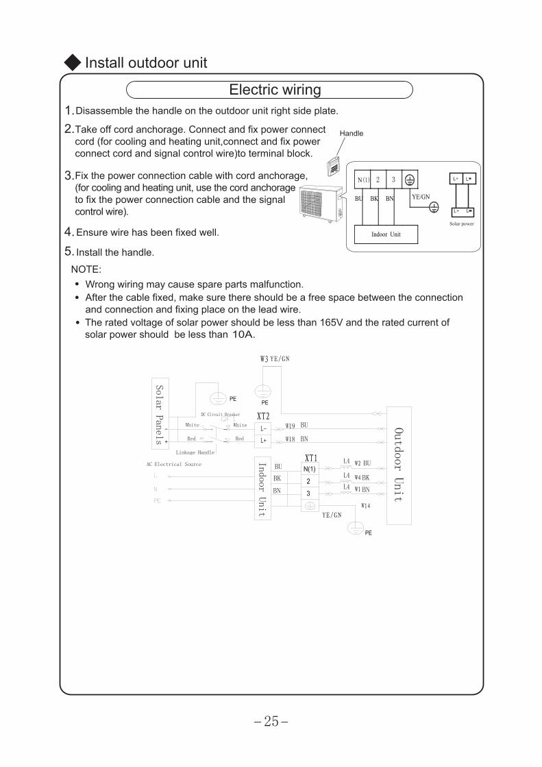
Install outdoor unit
Electric wiring
NOTE:Wrong wiring may cause spare parts malfunction.After the cable fixed, make sure there should be a free space between the connection and connection and fixing place on the lead wire.
3.
4.5.
1.2.
Disassemble the handle on the outdoor unit right side plate.
Take off cord anchorage. Connect and fix power connectcord (for cooling and heating unit,connect and fix powerconnect cord and signal control wire)to terminal block.
Fix the power connection cable with cord anchorage,(for cooling and heating unit, use the cord anchorageto fix the power connection cable and the signalcontrol wire).
Ensure wire has been fixed well.
Install the handle.
● The rated voltage of solar power should be less than 165V and the rated current of solar power should be less than 10A.
Solar power
YE/GN
Solar Panels
DC Circuit Breaker
White White
Red Red
Linkage Handle
AC Electrical Source
BU
BN
Indoor Unit
BU
BK
BN
BU
BK
BN
YE/GN
Outdoor Unit
N(1) 2 3
Indoor Unit
BU BK BN YE/GN
Ø
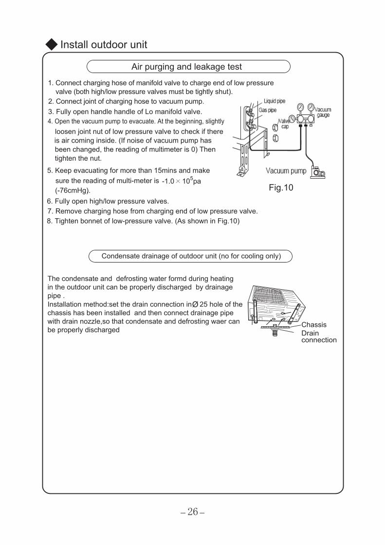
Air purging and leakage test
Condensate drainage of outdoor unit (no for cooling only)
The condensate and defrosting water formd during heating in the outdoor unit can be properly discharged by drainagepipe .Installation method:set the drain connection in 25 hole of the chassis has been installed and then connect drainage pipe with drain nozzle,so that condensate and defrosting waer can be properly discharged
ChassisDrainconnection
26
Install outdoor unit
5 -1.0 10 pa(-76cmHg)..
1. Connect charging hose of manifold valve to charge end of low pressure valve (both high/low pressure valves must be tightly shut).
2. Connect joint of charging hose to vacuum pump.3. Fully open handle handle of Lo manifold valve.4. Open the vacuum pump to evacuate. At the beginning, slightly
loosen joint nut of low pressure valve to check if there is air coming inside. (If noise of vacuum pump has been changed, the reading of multimeter is 0) Then tighten the nut.
5. Keep evacuating for more than 15mins and makesure the reading of multi-meter is
6. Fully open high/low pressure valves.7. Remove charging hose from charging end of low pressure valve.8. Tighten bonnet of low-pressure valve. (As shown in Fig.10)
Fig.10
27
Install PV-Module
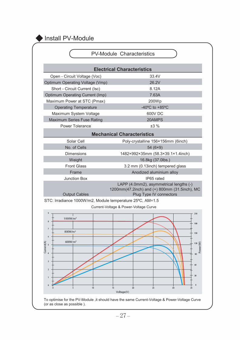
PV-Module Characteristics
Current-Voltage & Power-Voltage Curve
Open - Circuit Voltage (Voc) 33.4VOptimum Operating Voltage (Vmp) 26.2V
Short - Circuit Current (Isc) 8.12AOptimum Operating Current (Imp) 7.63AMaximum Power at STC (Pmax) 200Wp
Operating Temperature -40ºC to +85ºCMaximum System Voltage 600V DC
Maximum Series Fuse Rating 20AMPSPower Tolerance ±3 %
Solar Cell Poly-crystalline 156×156mm (6inch)No. of Cells 54 (6×9)Dimensions 1482×992×35mm (58.3×39.1×1.4inch)
Weight 16.8kg (37.0lbs.)Front Glass 3.2 mm (0.13inch) tempered glass
Frame Anodized aluminium alloyJunction Box IP65 rated
Output Cables
LAPP (4.0mm2), asymmetrical lengths (-)1200mm(47.2inch) and (+) 800mm (31.5inch), MC
Plug Type IV connectors
Electrical Characteristics
Mechanical Characteristics
STC: lrradiance 1000W/m2, Module temperature 25ºC, AM=1.5
To optimise for the PV-Module ,it should have the same Current-Voltage & Power-Voltage Curve (or as close as possible ).
28
Install PV-Module
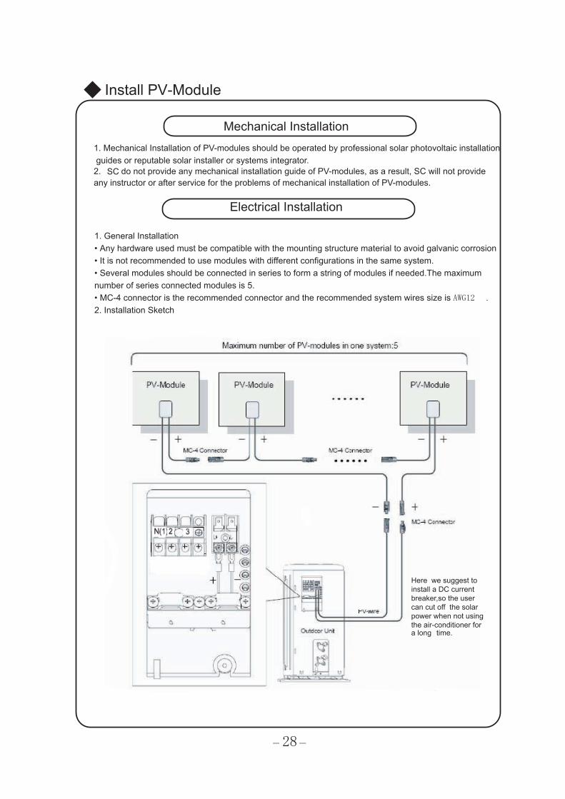
Mechanical Installation1. Mechanical Installation of PV-modules should be operated by professional solar photovoltaic installation guides or reputable solar installer or systems integrator.2. SC do not provide any mechanical installation guide of PV-modules, as a result, SC will not provideany instructor or after service for the problems of mechanical installation of PV-modules.
Electrical Installation
1. General Installation• Any hardware used must be compatible with the mounting structure material to avoid galvanic corrosion• It is not recommended to use modules with different configurations in the same system. • Several modules should be connected in series to form a string of modules if needed.The maximum number of series connected modules is 5.• MC-4 connector is the recommended connector and the recommended system wires size is AWG12 .2. Installation Sketch
Here we suggest to install a DC current breaker,so the user can cut off the solar power when not using the air-conditioner for a long time.
29
Install PV-Module
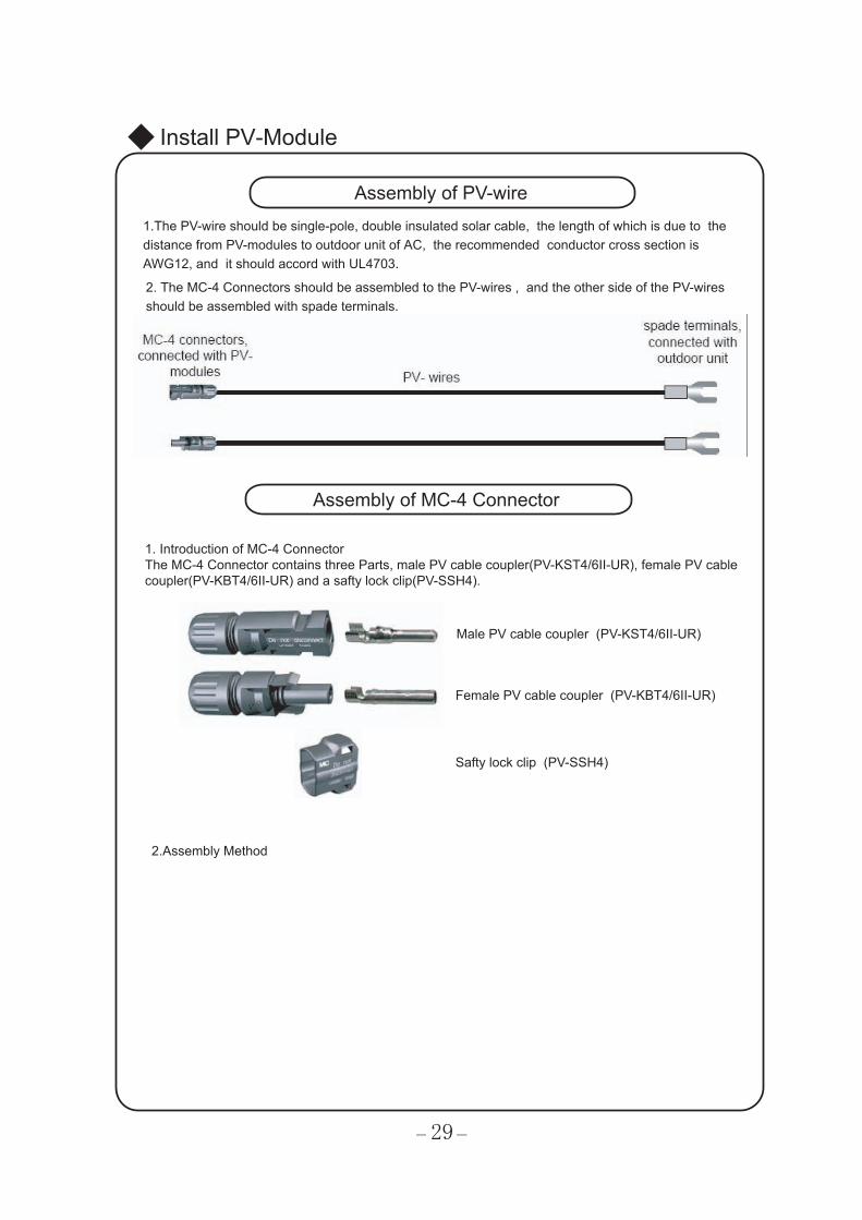
Assembly of PV-wire 1.The PV-wire should be single-pole, double insulated solar cable, the length of which is due to the distance from PV-modules to outdoor unit of AC, the recommended conductor cross section is AWG12, and it should accord with UL4703.
Assembly of MC-4 Connector
2. The MC-4 Connectors should be assembled to the PV-wires , and the other side of the PV-wires should be assembled with spade terminals.
1. Introduction of MC-4 ConnectorThe MC-4 Connector contains three Parts, male PV cable coupler(PV-KST4/6II-UR), female PV cable coupler(PV-KBT4/6II-UR) and a safty lock clip(PV-SSH4).
Male PV cable coupler (PV-KST4/6II-UR)
Female PV cable coupler (PV-KBT4/6II-UR)
2.Assembly Method
Safty lock clip (PV-SSH4)
30
Install PV-Module
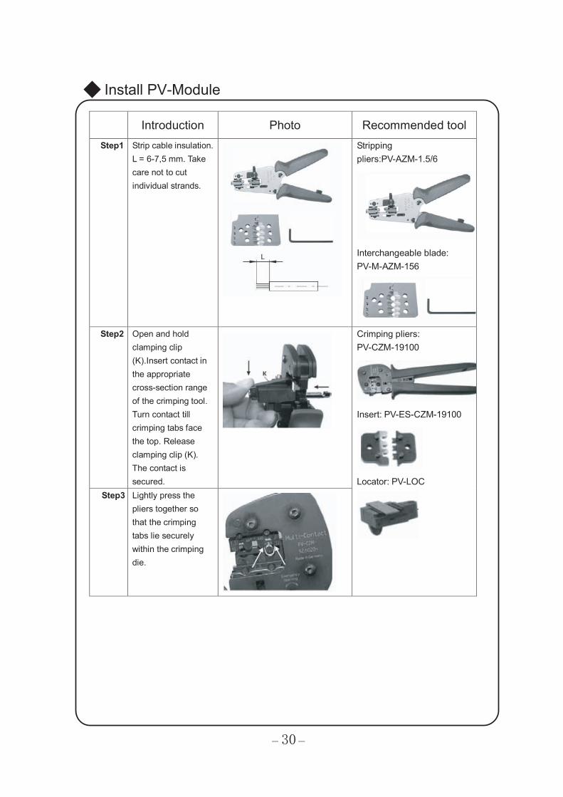
Introduction Photo Recommended tool Step1 Strip cable insulation.
L = 6-7,5 mm. Take care not to cut individual strands.
Stripping pliers:PV-AZM-1.5/6
Interchangeable blade: PV-M-AZM-156
Step2 Open and hold
clamping clip (K).Insert contact in the appropriate cross-section range of the crimping tool. Turn contact till crimping tabs face the top. Release clamping clip (K). The contact is secured.
Step3 Lightly press the pliers together so that the crimping tabs lie securely within the crimping die.
Crimping pliers: PV-CZM-19100
Insert: PV-ES-CZM-19100
Locator: PV-LOC
31
Install PV-Module
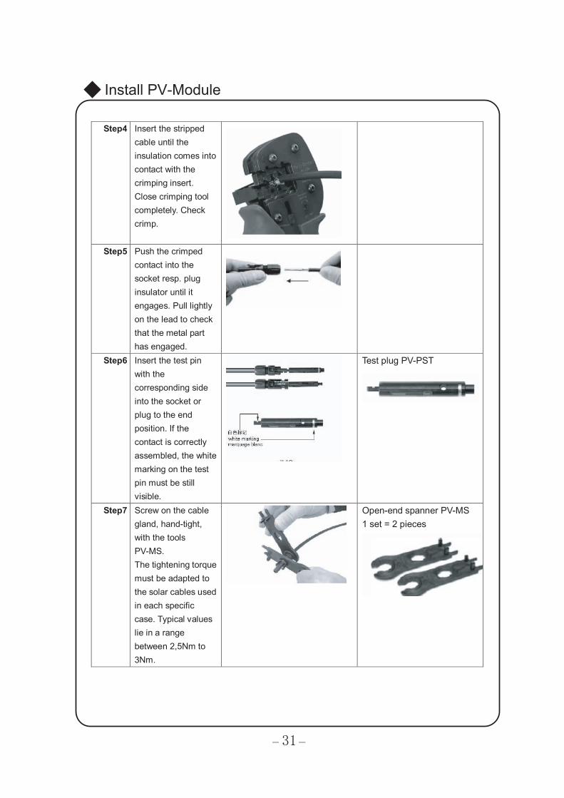
Step4 Insert the stripped cable until the insulation comes into contact with the crimping insert. Close crimping tool completely. Check crimp.
Step5 Push the crimped contact into the socket resp. plug insulator until it engages. Pull lightly on the lead to check that the metal part has engaged.
Step6 Insert the test pin with the corresponding side into the socket or plug to the end position. If the contact is correctly assembled, the white marking on the test pin must be still visible.
Test plug PV-PST
Step7 Screw on the cable gland, hand-tight, with the tools PV-MS. The tightening torque must be adapted to the solar cables used in each specific case. Typical values lie in a range between 2,5Nm to 3Nm.
Open-end spanner PV-MS 1 set = 2 pieces
32
Install PV-Module
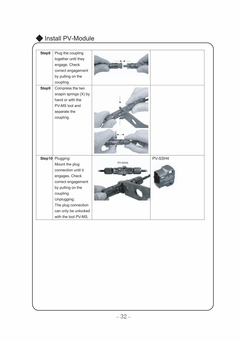
Step8 Plug the coupling together until they engage. Check correct engagement by pulling on the coupling.
Step9 Compress the two snapin springs (X) by hand or with the PV-MS tool and separate the coupling.
Step10 Plugging: Mount the plug connection until it engages. Check correct engagement by pulling on the coupling. Unplugging: The plug connection can only be unlocked with the tool PV-MS.
PV-SSH4
1.
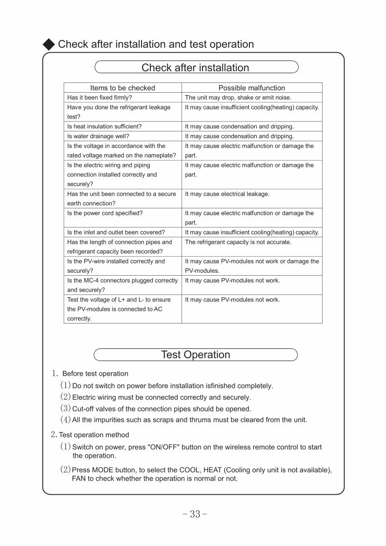
(1)Do not switch on power before installation isfinished completely.(2)Electric wiring must be connected correctly and securely.(3)Cut-off valves of the connection pipes should be opened.(4)
2.
(1)Switch on power, press "ON/OFF" button on the wireless remote control to start the operation.
(2)
Check after installation and test operation
Check after installation
Test Operation
Before test operation
All the impurities such as scraps and thrums must be cleared from the unit.
Test operation method
Press MODE button, to select the COOL, HEAT (Cooling only unit is not available), FAN to check whether the operation is normal or not.
33
Items to be checked Possible malfunction Has it been fixed firmly? The unit may drop, shake or emit noise. Have you done the refrigerant leakage test?
It may cause insufficient cooling(heating) capacity.
Is heat insulation sufficient? It may cause condensation and dripping. Is water drainage well? It may cause condensation and dripping. Is the voltage in accordance with the rated voltage marked on the nameplate?
It may cause electric malfunction or damage the part.
Is the electric wiring and piping connection installed correctly and securely?
It may cause electric malfunction or damage the part.
Has the unit been connected to a secure earth connection?
It may cause electrical leakage.
Is the power cord specified? It may cause electric malfunction or damage the part.
Is the inlet and outlet been covered? It may cause insufficient cooling(heating) capacity. Has the length of connection pipes and refrigerant capacity been recorded?
The refrigerant capacity is not accurate.
Is the PV-wire installed correctly and securely?
It may cause PV-modules not work or damage the PV-modules.
Is the MC-4 connectors plugged correctly and securely?
It may cause PV-modules not work.
Test the voltage of L+ and L- to ensure the PV-modules is connected to AC correctly.
It may cause PV-modules not work.
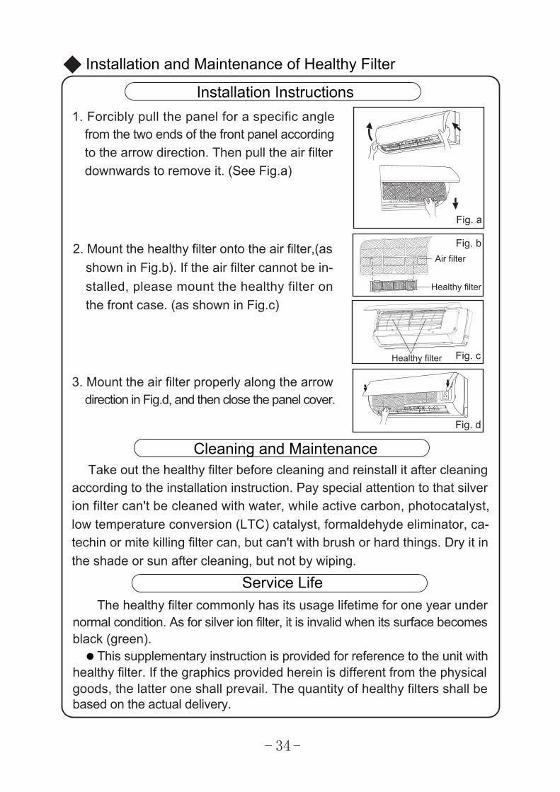
Fig. a
Installation Instructions1. Forcibly pull the panel for a specific angle
from the two ends of the front panel accordingto the arrow direction. Then pull the air filter
2. Mount the healthy filter onto the air filter,(asshown in Fig.b). If the air filter cannot be in-stalled, please mount the healthy filter on
3. Mount the air filter properly along the arrowdirection in Fig.d, and then close the panel cover.
ion filter can't be cleaned with water, while active carbon, photocatalyst, low temperature conversion (LTC) catalyst, formaldehyde eliminator, ca-
The healthy filter commonly has its usage lifetime for one year undernormal condition. As for silver ion filter, it is invalid when its surface becomes
according to the installation instruction. Pay special attention to that silverTake out the healthy filter before cleaning and reinstall it after cleaning
Installation and Maintenance of Healthy Filter
Cleaning and Maintenance
Service Life
●
Healthy filter
Air filter
Healthy filter
downwards to remove it. (See Fig.a)
the front case. (as shown in Fig.c)
Fig. b
Fig. c
Fig. d
techin or mite killing filter can, but can't with brush or hard things. Dry it inthe shade or sun after cleaning, but not by wiping.
black (green).
goods, the latter one shall prevail. The quantity of healthy filters shall bebased on the actual delivery.
This supplementary instruction is provided for reference to the unit withhealthy filter. If the graphics provided herein is different from the physical
34


Owner’s Manual
Owner’s Manual
COUNTRY STAR SDN BHD 437305Hwww.solarcoolairconditioner.com
Product improvement, specification and appearance in this manual are subject to change without prior notice .
66129923440