hotspot energy inc. solar air conditioner service manual
TRANSCRIPT
HotSpot Energy Inc. Solar Air Conditioner Service Manual ACDC12C / ACDC18C Indoor Units: ACDC12C-IDU ACDC18C-IDU Outdoor Units: ACDC12C-ODU ACDC18C-ODU Version 3
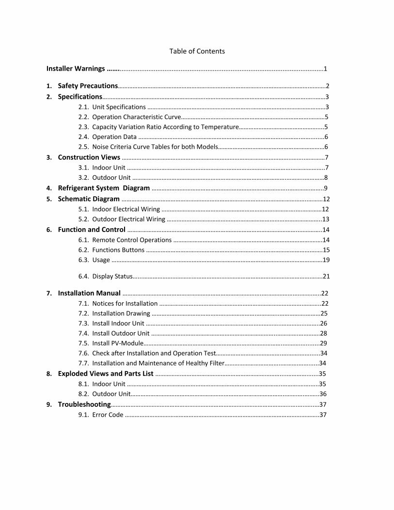
Table of Contents
Installer Warnings ……...................................................................................................................1
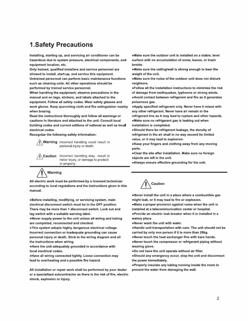
1. Safety Precautions……………………………………………………………………………..……………………….……….2
2. Specifications…..………………………………………………….………………………………….………………….…..……3
2.1. Unit Specifications ……………………………………………………….………………………………………3
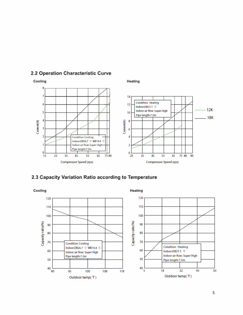
2.2. Operation Characteristic Curve…………………………………………………………………….………5
2.3. Capacity Variation Ratio According to Temperature…………………………………………....5
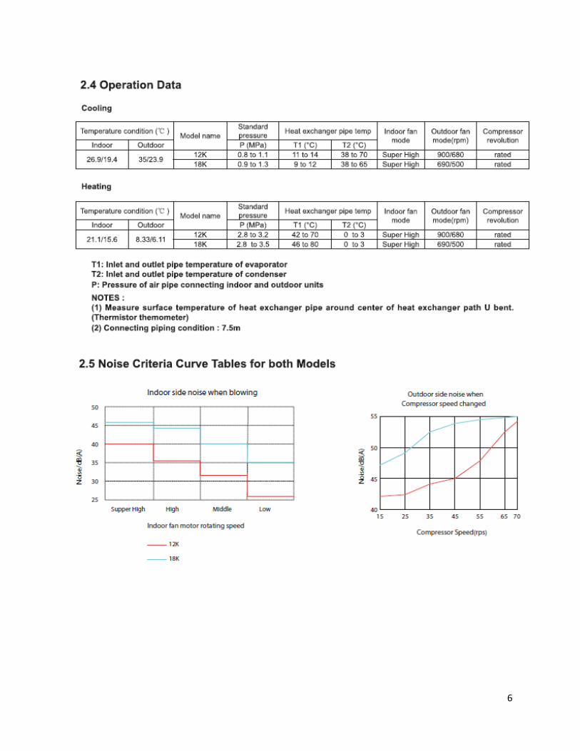
2.4. Operation Data ……………………………………………………………………………..……….……........6
2.5. Noise Criteria Curve Tables for both Models……………………………….……….………………6
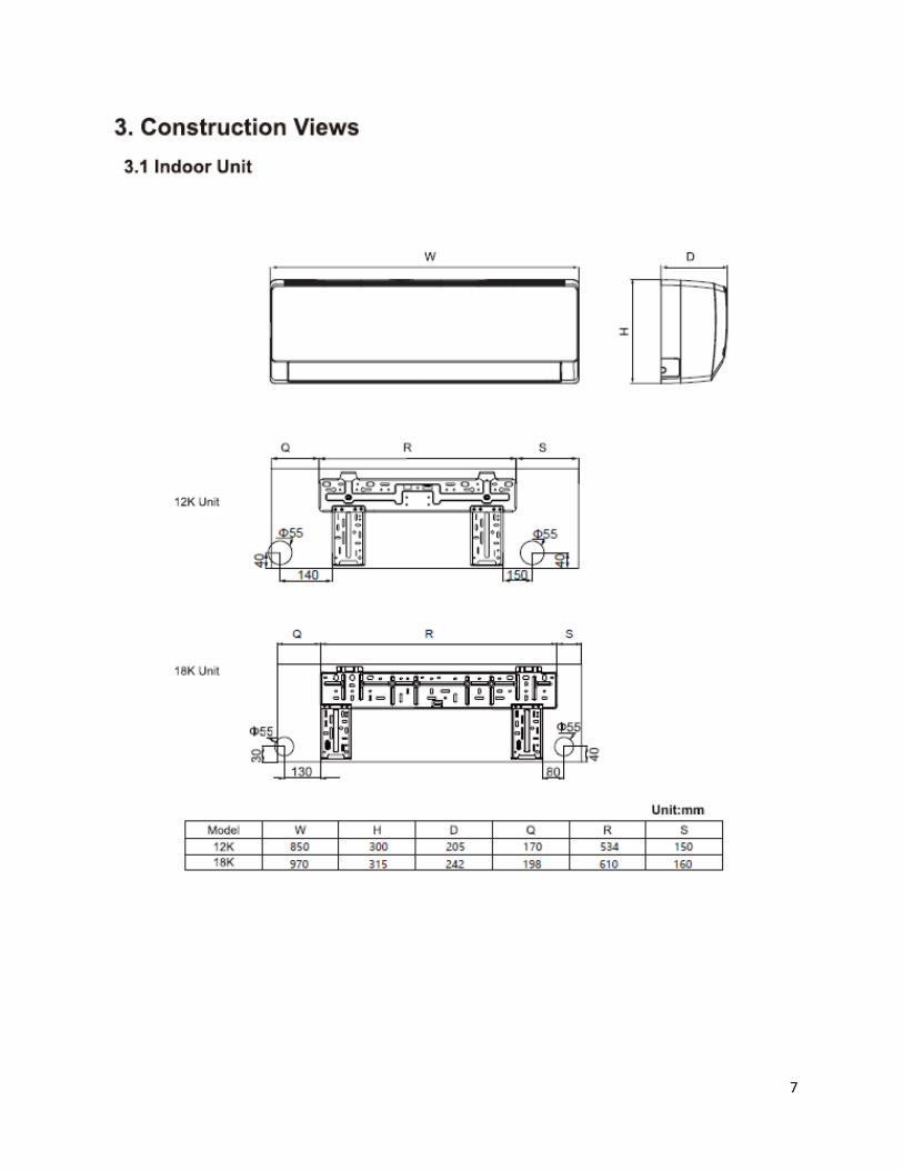
3. Construction Views …………………………………………………………………………………………..……..…………7
3.1. Indoor Unit …………………………………………………….………………………………….………………..7
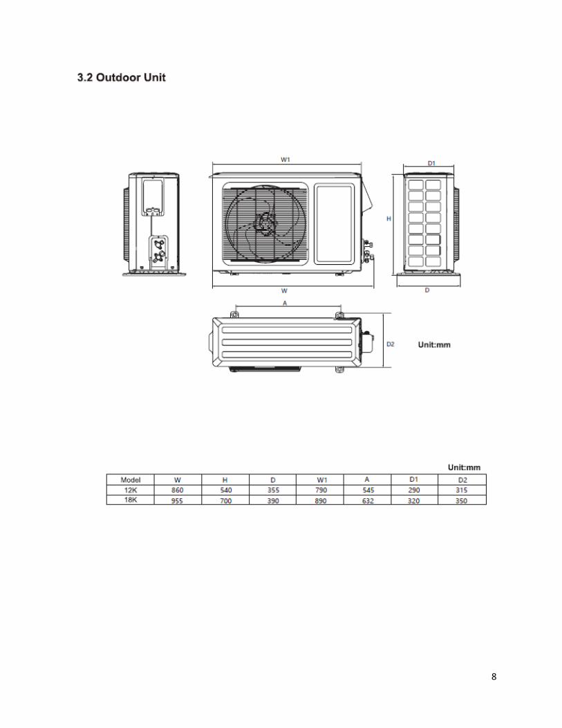
3.2. Outdoor Unit ……………………………………………………….……………..………….………..…………8
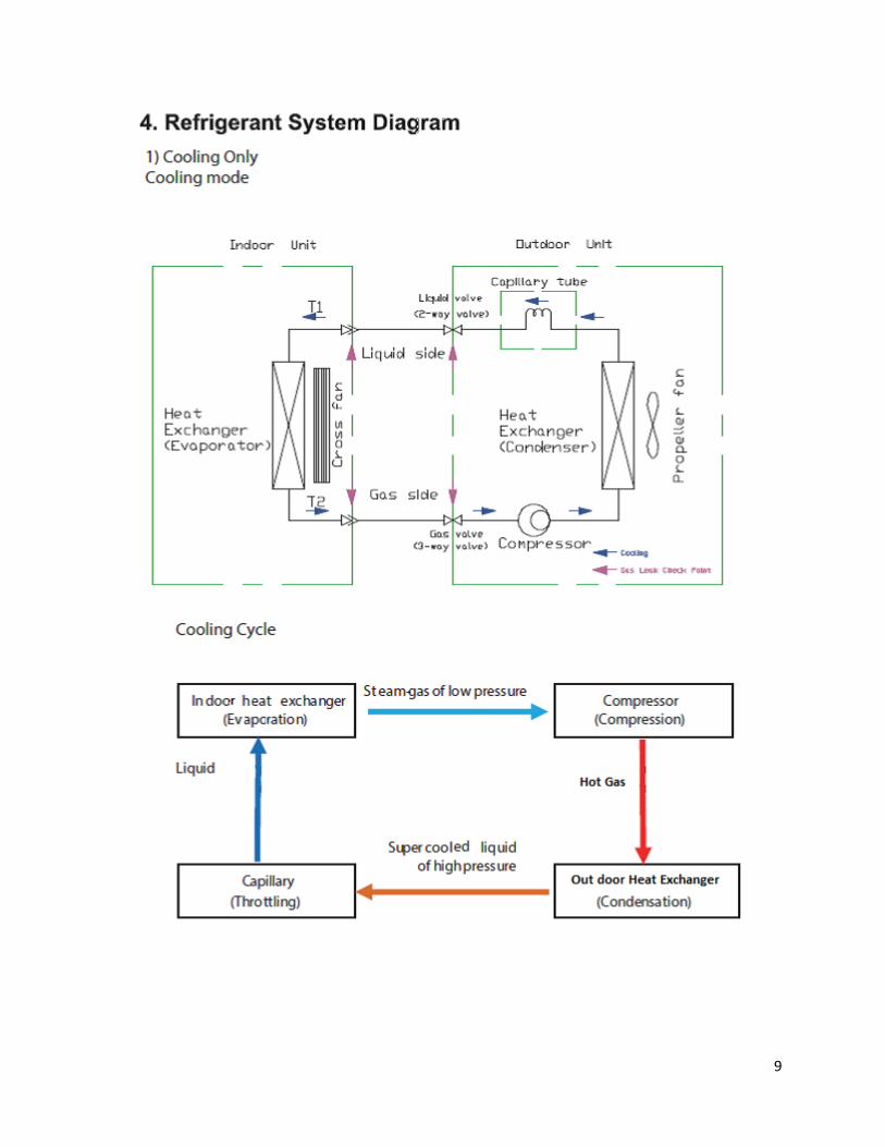
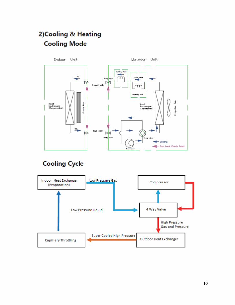
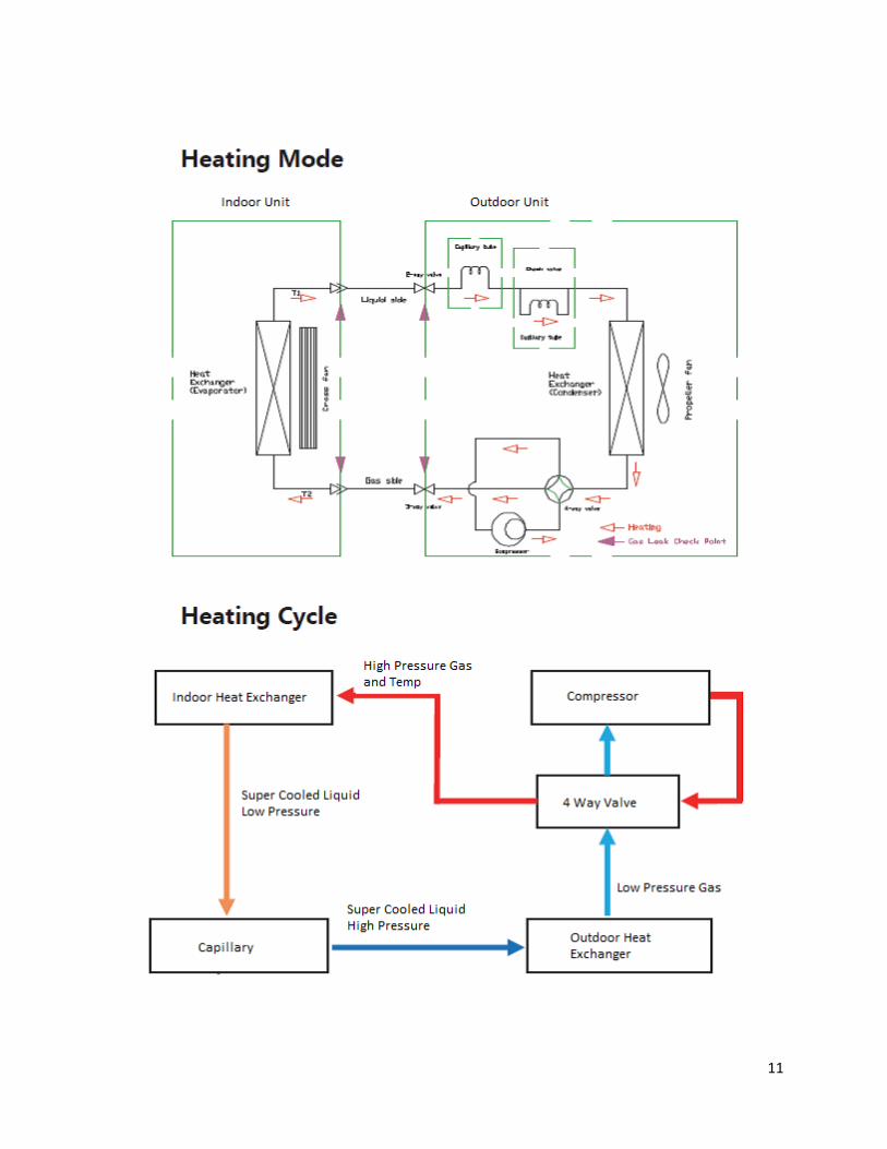
4. Refrigerant System Diagram ………………………………………….……………………………..………….……..9
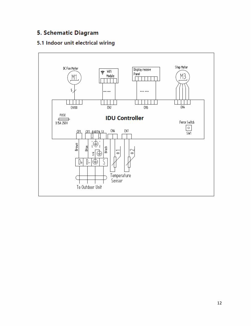
5. Schematic Diagram ………………………………………………………………….………………………………..………12
5.1. Indoor Electrical Wiring ………………………………………………………………………..……………12
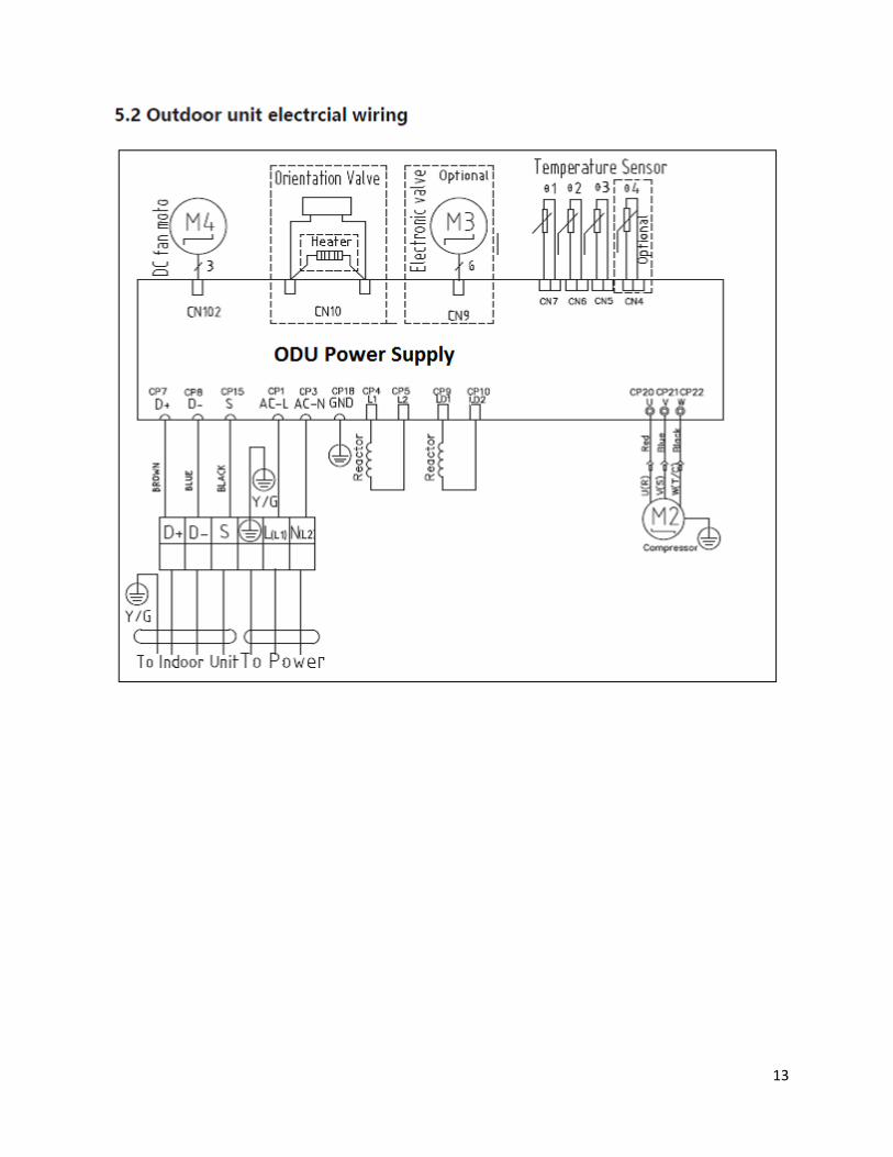
5.2. Outdoor Electrical Wiring …………………………………………………………………………………..13
6. Function and Control …………………………………………………….……………………………………..…………..14
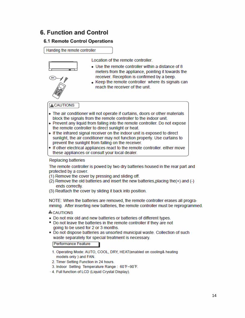
6.1. Remote Control Operations ………………………………………………..……………………….…….14
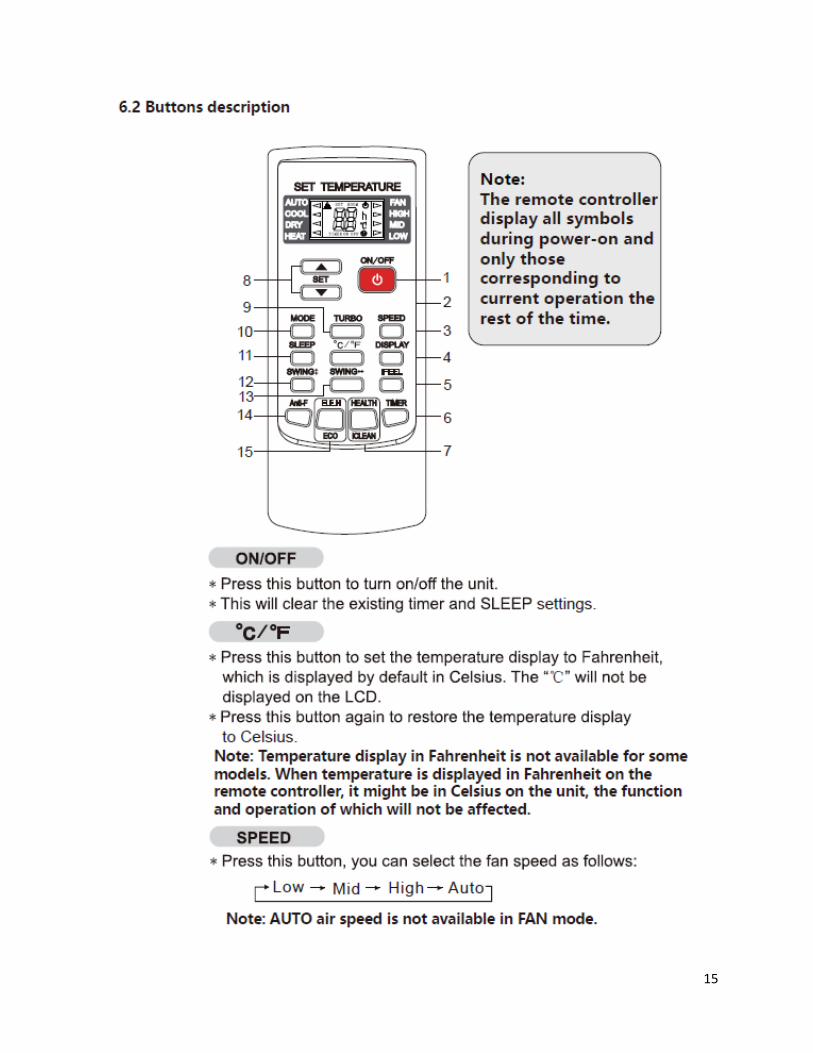
6.2. Functions Buttons …………………………………………………………….………………………….…….15
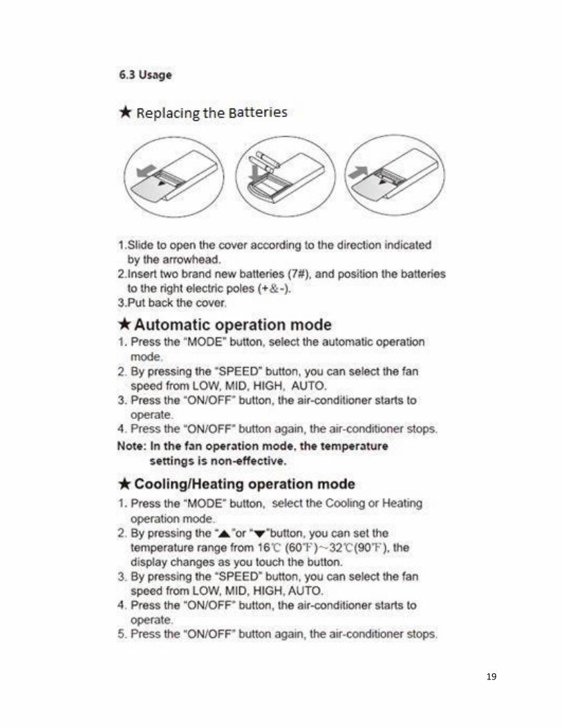
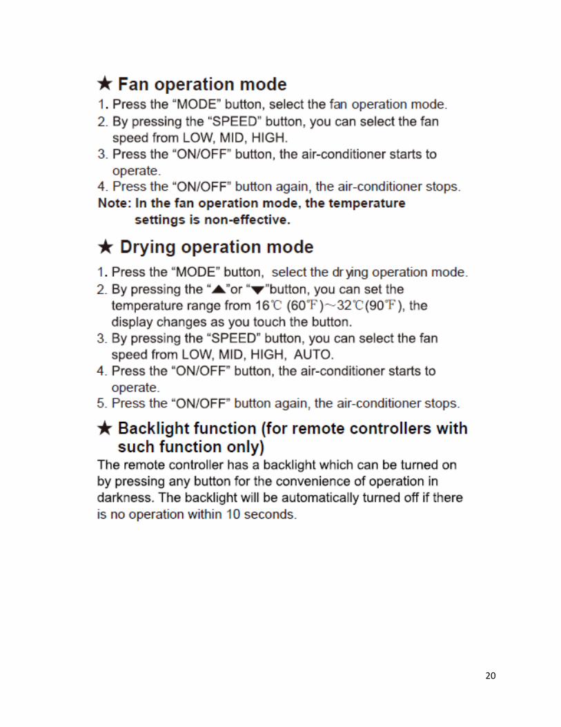
6.3. Usage ……………….………………………………………………………………………………………….…….19
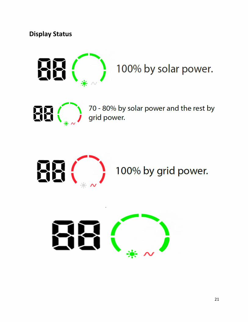
6.4. Display Status…...………………………………………………………………………………………….…….21
7. Installation Manual …………………………………………………………………………..……………….….…….…..22
7.1. Notices for Installation …………………………………………………………………………….………..22
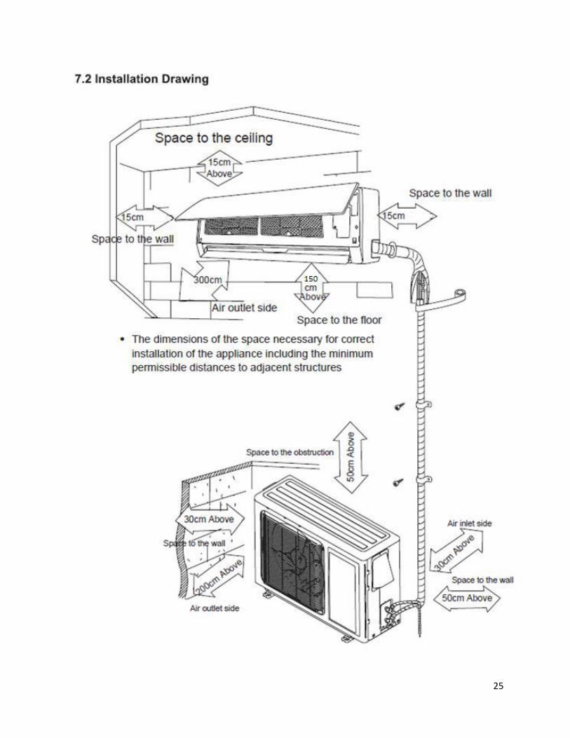
7.2. Installation Drawing ……………………………………………………….…………..…………….………25
7.3. Install Indoor Unit ………………………………………………………………………..…………...……..26
7.4. Install Outdoor Unit …………………………………………………………………..………….………….28
7.5. Install PV-Module…………………………………………………………………………..……….…........29
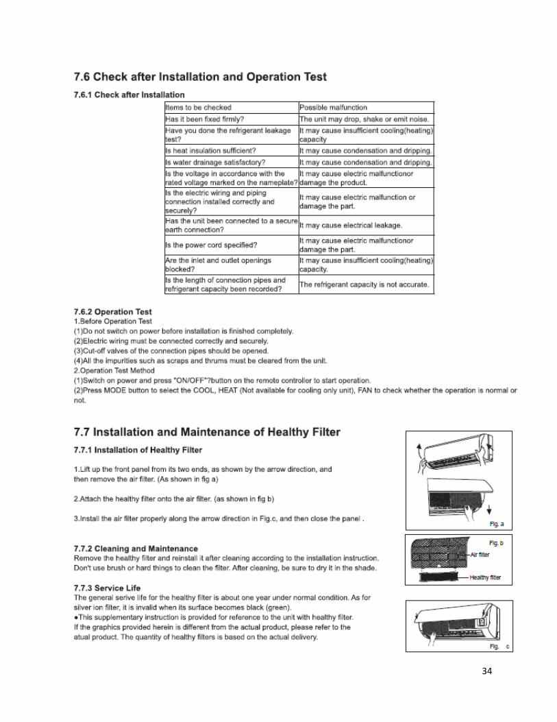
7.6. Check after Installation and Operation Test…………………………………..……….……......34
7.7. Installation and Maintenance of Healthy Filter……………………………..……….……......34
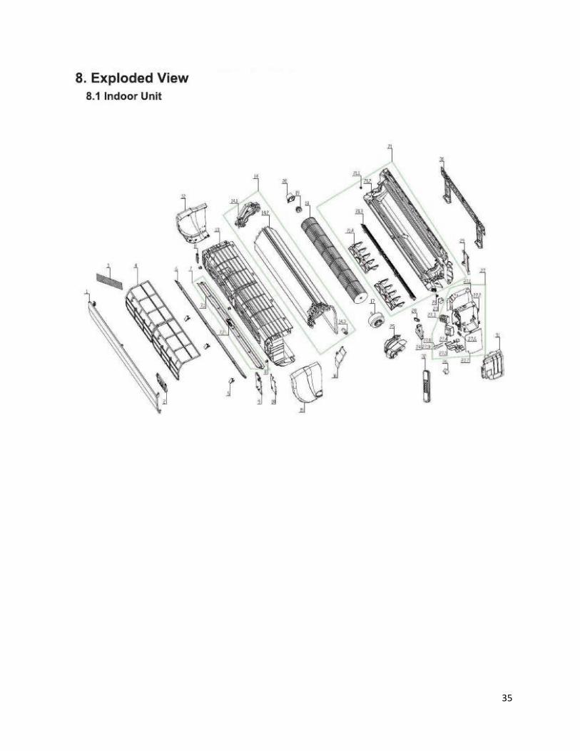
8. Exploded Views and Parts List …………….……………………………………………………....………….......35
8.1. Indoor Unit …………………………………………………………………………………..……….…….…..35
8.2. Outdoor Unit…………………………………………………………………………………..…….….….…..36
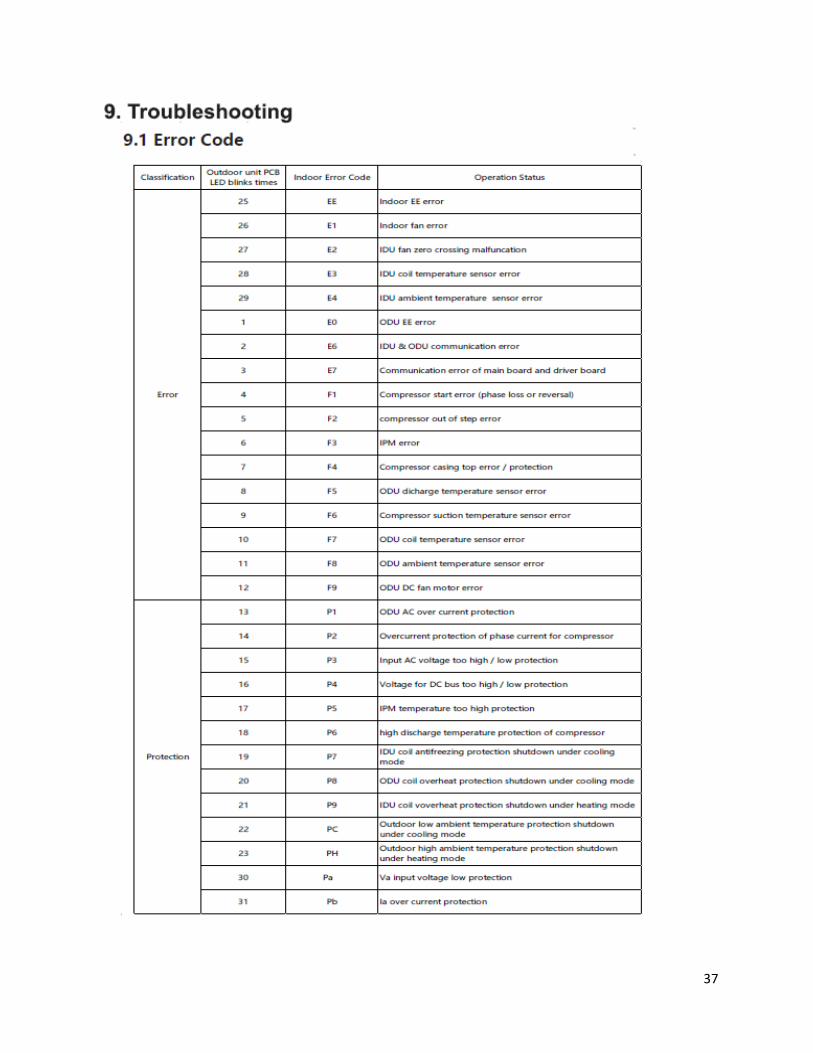
9. Troubleshooting………………………………………………………………………………………………..….…..…..…37
9.1. Error Code ………………………………………………………………………………………………………..37
1
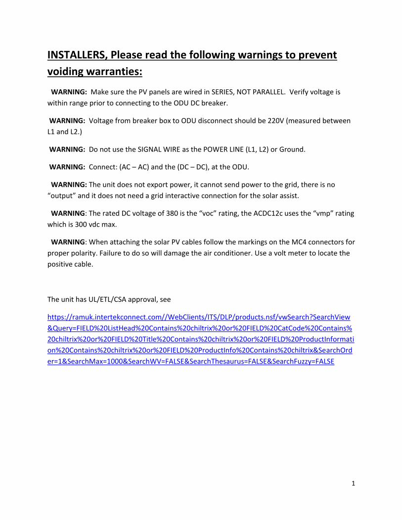
INSTALLERS, Please read the following warnings to prevent
voiding warranties:
WARNING: Make sure the PV panels are wired in SERIES, NOT PARALLEL. Verify voltage is
within range prior to connecting to the ODU DC breaker.
WARNING: Voltage from breaker box to ODU disconnect should be 220V (measured between
L1 and L2.)
WARNING: Do not use the SIGNAL WIRE as the POWER LINE (L1, L2) or Ground.
WARNING: Connect: (AC – AC) and the (DC – DC), at the ODU.
WARNING: The unit does not export power, it cannot send power to the grid, there is no
“output” and it does not need a grid interactive connection for the solar assist.
WARNING: The rated DC voltage of 380 is the “voc” rating, the ACDC12c uses the “vmp” rating
which is 300 vdc max.
WARNING: When attaching the solar PV cables follow the markings on the MC4 connectors for
proper polarity. Failure to do so will damage the air conditioner. Use a volt meter to locate the
positive cable.
The unit has UL/ETL/CSA approval, see
https://ramuk.intertekconnect.com//WebClients/ITS/DLP/products.nsf/vwSearch?SearchView
&Query=FIELD%20ListHead%20Contains%20chiltrix%20or%20FIELD%20CatCode%20Contains%
20chiltrix%20or%20FIELD%20Title%20Contains%20chiltrix%20or%20FIELD%20ProductInformati
on%20Contains%20chiltrix%20or%20FIELD%20ProductInfo%20Contains%20chiltrix&SearchOrd
er=1&SearchMax=1000&SearchWV=FALSE&SearchThesaurus=FALSE&SearchFuzzy=FALSE
2
3
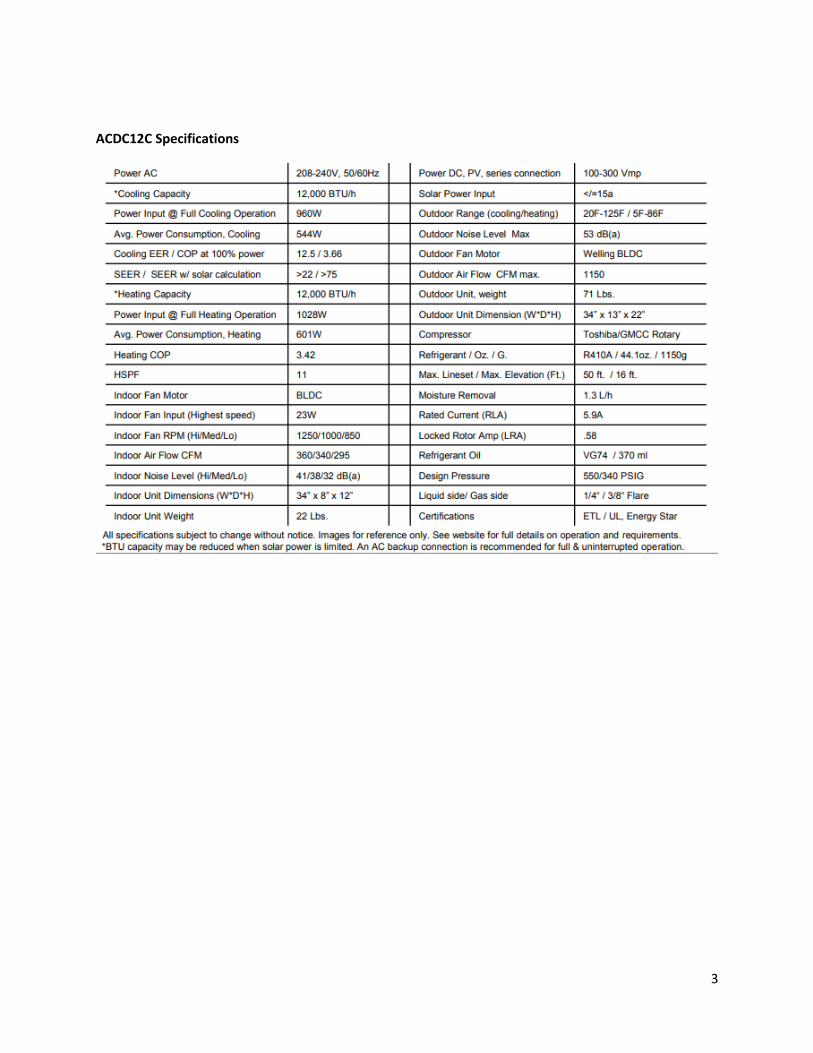
ACDC12C Specifications
4
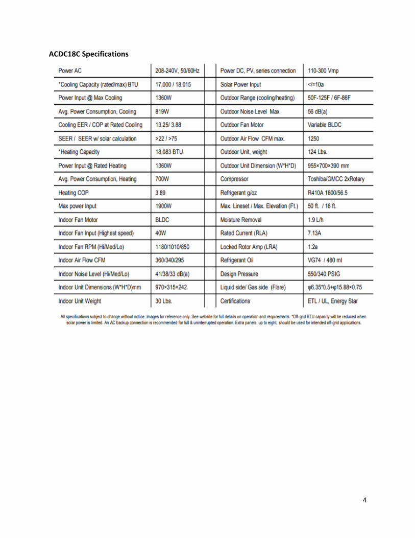
ACDC18C Specifications
5
6
7
8
9
10
11
12
13
14
15

16
17
18
19
20
21
Display Status
22
All solar with Grid available.
7. Installation Manual
7.1 Notices for Installation
Caution
1. The unit should be installed only by authorized service center according to local or
government regulations and in compliance with the manual.
2. Before installing, please contact with local authorized maintenance center, if the unit is
not installed by the authorized service center, the malfunction may not be solved die to
inconvenient contact between the user and the service personnel.
3. When removing the unit to the other place, please firstly contact with the local
authorized service center.
4. Warning: before obtaining access to terminals, all supply circuits must be disconnected.
5. For appliances with y attachment, the instructions shall contain the substance of the
following. If the supply cord is damaged, it must be replaced by the manufacture, its
service agent or similarly qualified persons in order to avoid a hazard.
6. The appliance must be positioned so that the plug is accessible.
7. The temperature of refrigerant line will be high: please keep the interconnection cable
away from the copper tube.
8. The instruction shall state the substance of the following:
This appliance is not intended for use by persons (including children with reduced
physical, sensory or mental capabilities, or lack of experience and knowledge, unless
they have been given supervision or instruction concerning use of the appliance by a
person responsible for their safety.
Children should be supervised to ensure that they do not play with the appliance.
7.1.1 Installation Site Instructions
Proper installation site is vital for correct and efficient operation of the unit. Avoid the following
sites where:
Strong heat sources, vapors, flammable gas or volatile liquids are emitted.
23
High-frequency electro-magnetic waves are generated by radio equipment,
welders and medical equipment.
Salt-laden air prevails (such as close to coastal areas).
The air is contaminated with industrial vapors and oils.
The air contains Sulphur’s gas such as in hot spring zones.
Corrosion or poor air quality exists.
7.1.2 Installation Site of Indoor Unit
1. The air inlet and outlet should be away from the obstructions, Ensure the air can be
blown through the whole room
2. Select a site where the condensate can be easily drained out, and where it is easily
connected to outdoor unit.
3. Select a place where it is out of reach of children.
4. Select a place where the wall is strong enough to withstand the full weight and vibration
of the unit.
5. Be sure to leave enough space to allow access for routine maintenance, the installation
site should be 150cm or more above the floor.
6. Select a place about 1m or more away from TV set or any other electric appliance.
7. Select a place where the filter can be easily taken out.
8. Make sure that the indoor unit is installed in accordance with installation dimension
instructions
9. Do not use the unit in the laundry or by swimming pool etc.
7.1.3 Installation Site of Outdoor Unit
1. Select a site where noise and outflow air emitted by the unit will not annoy neighbors.
2. Select a site where there is sufficient ventilation.
3. Select a site where there is no obstruction blocking the inlet and outlet.
4. The site should be able to withstand the full weight and vibration.
5. Select a dry place, but do not expose the unit to strong wind.
6. Make sure that the outdoor unit is installed in accordance with the installation
instructions and is convenient for maintenance and repair.
7. The height difference between indoor and outdoor units is within 5m and the length of
the connecting rubbing does not exceed 15m.
8. Select a place where it is out of reach of children.
9. Select a place where the unit does not have negative impact on pedestrians or on the
city.
24
7.1.4 Safety Precaution for Electric Appliances
1. A dedicated power supply circuit should be used in accordance with local electrical
safety regulations.
2. Don’t drag the power cord with excessive force.
3. The unit should be reliably earthed and connected to an exclusive earth device by the
professionals.
4. The air switch must have the functions of magnetic tripping and heat tripping to prevent
short circuit and overload.
5. The minimum distance between the unit and combustive surface is 1.5m.
6. The appliance shall be installed in accordance with national wiring regulations.
7. An all pole disconnection switch with a contact separation of at least 3mm in all poles
should be connected in fixed wiring.
Note:
Make sure the there is a suitable breaker in the panel to provide L1 & L2 in the service
panel.
Inadequate or incorrect electrical connections may cause electric shock or fire.
7.1.5 Grounding Requirements
1. Air conditioner is type I electric appliance. Please ensure that the unit is reliably
grounded.
2. The yellow-green wire in the air conditioner is the grounding wire which cannot be used
for other purposes. Improper grounding may cause electric shock.
3. The earth resistance should accord to the national electrical code.
4. The power must have reliable grounding terminal. Please do not connect the grounding
wire with the following:
Gas pipe, Sewer pipe, or other place that is considered unreliable.
5. The model and rated values of the breaker should accord with the label on the outdoor
unit.
25
26
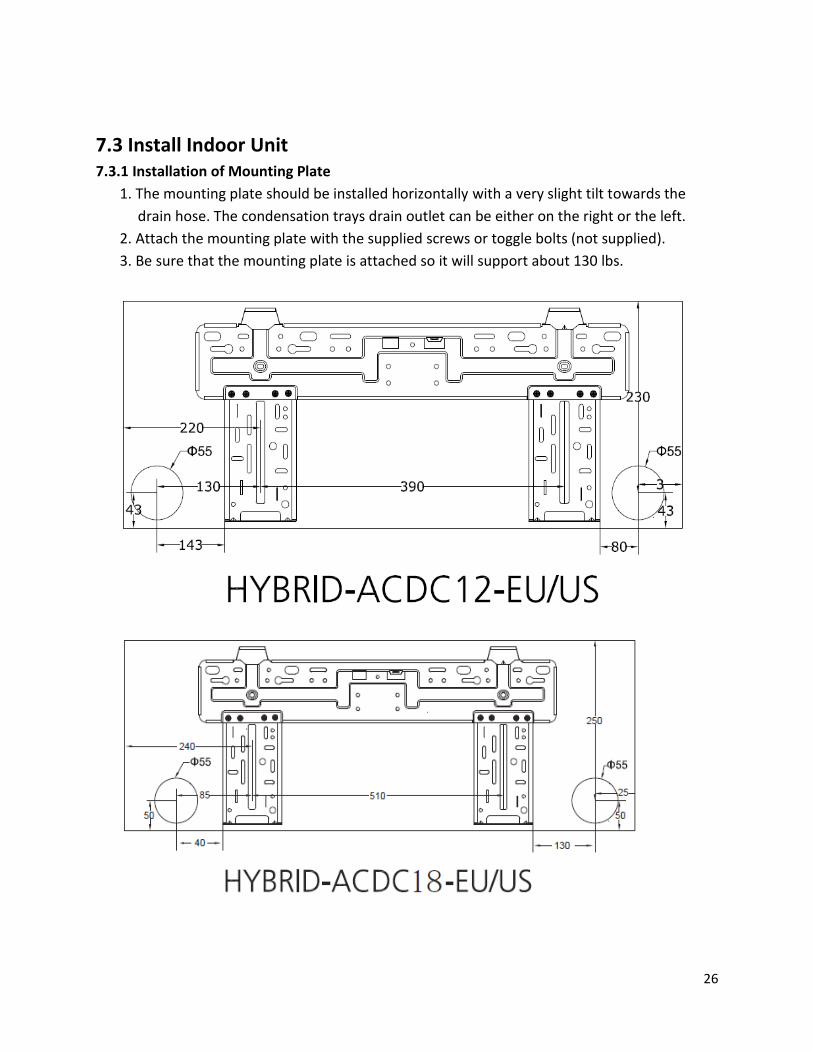
7.3 Install Indoor Unit 7.3.1 Installation of Mounting Plate
1. The mounting plate should be installed horizontally with a very slight tilt towards the
drain hose. The condensation trays drain outlet can be either on the right or the left.
2. Attach the mounting plate with the supplied screws or toggle bolts (not supplied).
3. Be sure that the mounting plate is attached so it will support about 130 lbs.

27
7.3.2 Drilling Piping Hole
1. Slant the piping hole slightly downward to the outdoor side.
2. Insert the piping sleeve into the hole from the inside to prevent the line-set and cabling
from getting damaged when passing through the hole.
7.3.3 Installation of Drain Hose
1. Connect the drain hose to the indoor unit. Use the rubber belt to secure the connection.
2. Put the drain hose into the insulating tube.
3. Wrap the insulating tube with tape to prevent shifting 0r the tube. Slant the insulating
tube into the wall exit hole with the tube slanting downward.
7.3.4 Connecting the Indoor to Outdoor Cable
1. Open the front panel.
2. Remove the wiring cover, connect the power cord to the terminal board as shown in
figure 1.
3. Pass the control cable through the access hole in the rear of the unit.
4. Reinstall the cord clamp and access cover.
5. Reinstall the front cover.
28
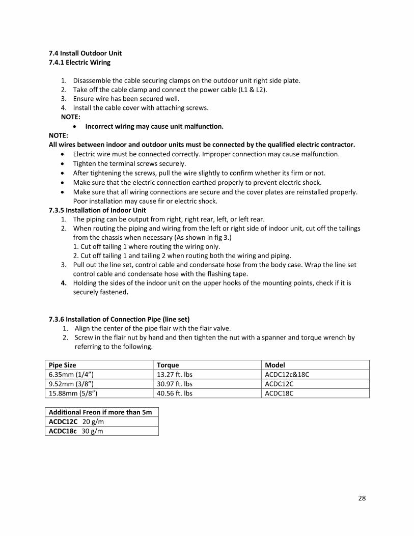
7.4 Install Outdoor Unit 7.4.1 Electric Wiring
1. Disassemble the cable securing clamps on the outdoor unit right side plate. 2. Take off the cable clamp and connect the power cable (L1 & L2). 3. Ensure wire has been secured well. 4. Install the cable cover with attaching screws. NOTE:
Incorrect wiring may cause unit malfunction. NOTE: All wires between indoor and outdoor units must be connected by the qualified electric contractor.
Electric wire must be connected correctly. Improper connection may cause malfunction.
Tighten the terminal screws securely.
After tightening the screws, pull the wire slightly to confirm whether its firm or not.
Make sure that the electric connection earthed properly to prevent electric shock.
Make sure that all wiring connections are secure and the cover plates are reinstalled properly. Poor installation may cause fir or electric shock.
7.3.5 Installation of Indoor Unit 1. The piping can be output from right, right rear, left, or left rear. 2. When routing the piping and wiring from the left or right side of indoor unit, cut off the tailings
from the chassis when necessary (As shown in fig 3.) 1. Cut off tailing 1 where routing the wiring only. 2. Cut off tailing 1 and tailing 2 when routing both the wiring and piping.
3. Pull out the line set, control cable and condensate hose from the body case. Wrap the line set control cable and condensate hose with the flashing tape.
4. Holding the sides of the indoor unit on the upper hooks of the mounting points, check if it is securely fastened.
7.3.6 Installation of Connection Pipe (line set)
1. Align the center of the pipe flair with the flair valve. 2. Screw in the flair nut by hand and then tighten the nut with a spanner and torque wrench by
referring to the following.
Pipe Size Torque Model
6.35mm (1/4”) 13.27 ft. lbs ACDC12c&18C
9.52mm (3/8”) 30.97 ft. lbs ACDC12C
15.88mm (5/8”) 40.56 ft. lbs ACDC18C
Additional Freon if more than 5m
ACDC12C 20 g/m
ACDC18c 30 g/m
29
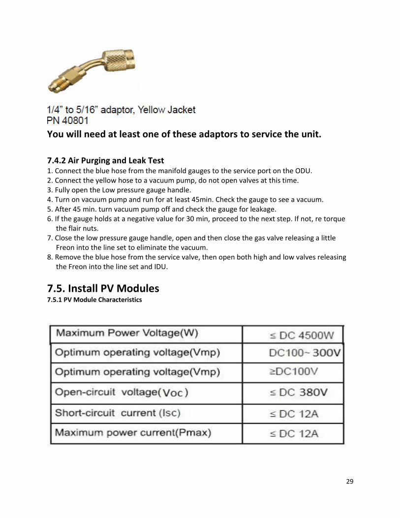
You will need at least one of these adaptors to service the unit.
7.4.2 Air Purging and Leak Test 1. Connect the blue hose from the manifold gauges to the service port on the ODU. 2. Connect the yellow hose to a vacuum pump, do not open valves at this time. 3. Fully open the Low pressure gauge handle. 4. Turn on vacuum pump and run for at least 45min. Check the gauge to see a vacuum. 5. After 45 min. turn vacuum pump off and check the gauge for leakage. 6. If the gauge holds at a negative value for 30 min, proceed to the next step. If not, re torque
the flair nuts. 7. Close the low pressure gauge handle, open and then close the gas valve releasing a little
Freon into the line set to eliminate the vacuum. 8. Remove the blue hose from the service valve, then open both high and low valves releasing
the Freon into the line set and IDU.
7.5. Install PV Modules 7.5.1 PV Module Characteristics
30
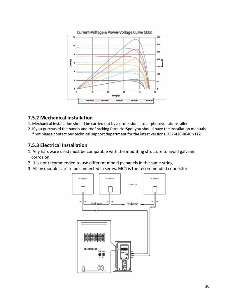
7.5.2 Mechanical installation 1. Mechanical installation should be carried out by a professional solar photovoltaic installer. 2. If you purchased the panels and roof racking form HotSpot you should have the installation manuals,
if not please contact our technical support department for the latest versions. 757-410-8640 x112
7.5.3 Electrical Installation 1. Any hardware used must be compatible with the mounting structure to avoid galvanic
corrosion. 2. It is not recommended to use different model pv panels in the same string. 3. All pv modules are to be connected in series. MC4 is the recommended connector.
31
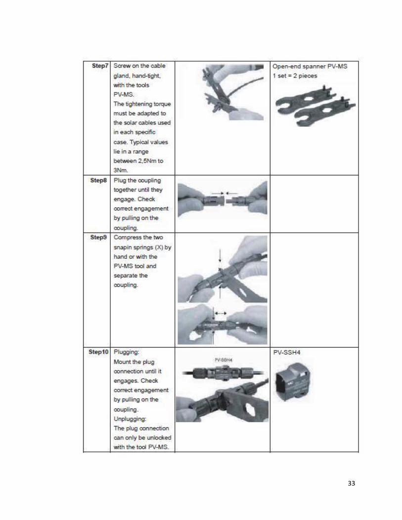
32
33
34
35

36
37