soil & tillage research - mcgill university · (pro e) and then imported into ansys/ls-dyna....
TRANSCRIPT

Soil & Tillage Research 145 (2015) 157–170
Finite element simulation of soil failure patterns under soil bin andfield testing conditions
A.A. Tagar a,b, Ji Changying a,*, Jan Adamowski c, Julien Malard c, Chen Shi Qi a,Ding Qishuo a, N.A. Abbasi c
aCollege of Engineering, Nanjing Agricultural University, Nanjing 210031, PR Chinab Faculty of Agricultural Engineering, Sindh Agriculture University, Tandojam 70060, PakistancDepartment of Bioresource Engineering, McGill University, Sainte-Anne-de-Bellevue, Quebec H9X3V9, Canada
A R T I C L E I N F O
Article history:Received 5 December 2013Received in revised form 30 August 2014Accepted 1 September 2014
Keywords:Consistency limitsFinite element methodSticky pointSoil physical and mechanical propertiesPaddy soil
A B S T R A C T
Finite element modeling (FEM) of soil physical behavior can provide information which is difficult orimpossible to obtain experimentally. This method has been applied by many researchers to study soilcompaction, acting forces on tools, stress distribution in soils and soil failure patterns. The great majorityof studies that have investigated soil failure patterns have been limited to in-laboratory soil bins, withfew tests being done under field conditions. However, it is difficult to simulate actual soil conditions in asoil bin. This study used FEM for the simulation of the soil failure patterns as linked to consistency limitsand sticky point of soil, comparing the simulation results with soil failure patterns observed in the soil binand in the field. Results showed that FEM is a useful tool to simulate soil failure patterns; however,simulation models correlated better with soil bin than with field test results. The results also showed thepresence of a direct relationship between soil failure patterns and the consistency limits of the soil, bothin the soil bin and in the field. However, soil bin results were not satisfactorily verified in the field, inparticular as the failure patterns were also found to be affected by the roots of the stubbles in the field. Itis concluded that FEM can provide accurate simulation of soil failure patterns under soil bin testconditions, but that soil bin results did not satisfactorily represent results from the field.
ã 2014 Elsevier B.V. All rights reserved.
Contents lists available at ScienceDirect
Soil & Tillage Research
journa l homepage: www.e lsev ier .com/ locate /st i l l
1. Introduction
Numerical methods are helpful in understanding and describ-ing soil cutting processes and soil–tool interactions. Karmakar andKushwaha (2006) identified three numerical methods to model thesoil cutting process, namely the finite element method (FEM), thediscrete element method (DEM) and computational fluid dynamics(CFD). The discrete element method (DEM) is based on a promisingapproach for constructing a high-fidelity model to describe thesoil-tillage tool interaction (Shmulevich, 2010). However, thedetermination of model parameters to control the soil void ratioand the shape of particles, as well as the modeling of breakage andthe formation of aggregates of varying sizes and shapes, remainsignificant challenges and limit the application of DEM for practicalengineering problems (Abo Al-Kheer et al., 2011b). Computationalfluid dynamics (CFD) can be used to model soil–tool interactions(Karmakar and Kushwaha, 2006). Soil dynamic behavior using theCFD simulation will help in tool design and its optimization with
* Corresponding author. Tel.: +86 13914706344.E-mail address: [email protected] (A.A. Tagar).
http://dx.doi.org/10.1016/j.still.2014.09.0060167-1987/ã 2014 Elsevier B.V. All rights reserved.
different shapes in order to reduce tool draft and energy demandover a wide speed range, and help model different types of soilsbased on their visco-plastic parameters. However, further researchis needed before CFD can be used to model soil–tool interactionswith confidence (Coetzee and Els, 2009). On the other hand, thefinite element method (FEM) has been used by many researchers inorder to design tillage tools and to investigate the interactionbetween soil and tillage implements. FEM can be used to study soilcompaction, acting forces on tools, stress distribution in soil andsoil failure patterns (Raper and Erbach, 1990; Aluko and Chandler,2004; Shahab Davoudi et al., 2008); however the continuityassumption in FEM does not allow crack propagation in soil (Jafariet al., 2006). Coleman and Perumpral (1974) pointed out that in soilmechanics research, the FEM method is capable of providinginformation which is difficult or impossible to obtain experimen-tally. Later, Yong and Hanna (1977) modeled soil cutting by simpleplane (two-dimensional) blades, and Liu Yan and HouZhi-Min(1985) and Chi and Kushwaha (1987, 1989) applied FEM to thestudy of three-dimensional soil cutting with narrow blades. FEM isalso appropriate for the analysis of soil cutting problems whereshear failure with significant plastic deformation occurs (Aluko,2008).

158 A.A. Tagar et al. / Soil & Tillage Research 145 (2015) 157–170
The performance of agricultural implements and the resultingsoil tilth depend largely on the mechanical behavior of soils(Rajaram and Erbach, 1998). Soil failure patterns are one of themost important indices to assess the mechanical behavior of soilsunder varied soil and tool conditions. Indeed, Abo Al-Kheer et al.,(2011a) concluded that the variation in soil failure patterns can beattributed to the wide variations in mechanical behavior of the soil.Previous studies of soil cutting have identified six types of soilfailure patterns, namely collapse, brittle, chip-forming, bending,flow and flow with considerable bending in different soil types(Elijah and Weber, 1971; Rajaram and Gee-Clough, 1988; Rajaramand Erbach, 1996; Tagar et al., 2014). Collapse failure, which occursin dry soils, involves the collapse of soil structure when a mass of asoil in front of the tool is crushed (Rajaram, 1990) and is similar tothe shear plane-type failure as described by Elijah and Weber(1971). Brittle failure occurs in moist soils due to the propagation oftensile cracks (Chandler, 1984; Hatibu, 1987). Chip-forming failure,or plastic type failure, occurs in wet unsaturated soil conditionswhen the soil is removed in the form of chips similar to the chipsformed in metal cutting (Rajaram and Erbach, 1996; Rajaram andGee-Clough, 1988). Flow failure occurs in wet saturated soilconditions due to the mere physical displacement of the soil(Rajaram and Erbach, 1996), and bending failure is similar to flowfailure but also shows some strain in the vertical direction (Elijahand Weber,1971). Flow with considerable bending failure occurs atthe sticky point of soil and is similar to flow failure but withconsiderable bending and no strains of elements (Tagar et al.,2014).
Rajaram and Erbach (1996, 1998) concluded that, to betterunderstand tillage, research should be directed towards explainingvarious soil failure patterns and the resulting physical propertychanges. Indeed, Mamman and Oni (2005) carried out a study toinvestigate the effect of draught on the performance of modelchisel furrowers. They concluded that there were no optimumvalues of tool speed or tillage depth for which the draught of themodel tools were at a minimum. Therefore they suggested that thechoice of model tool should depend on soil failure pattern atshallow depths, as well as on the size and quality of furrowscreated at deeper depths. Numerous studies have been conductedon soil failure patterns (e.g., Elijah and Weber,1971; Stafford 1979a;Rajaram and Gee-Clough, 1988; Wang and Gee-Clough, 1993;Rajaram and Erbach, 1997, 1998, 1999; Aluko and Seig, 2000;Makanga et al., 2010); however, despite this large number of
Fig. 1. Finite element meshing of soil and
studies, a thorough understanding of soil failure patterns has notyet been achieved.
Of the large number of studies having investigated soil failurepatterns, the vast majority have been limited to in-laboratory soilbins, with only a few tests being done under field conditions (e.g.,Elijah and Weber, 1971; Hemmat et al., 2012). The justifications forsoil bin studies include: better control of soil physical parameters(Stafford, 1979b) and the setting of operation variables (Wegscheidand Myers, 1967), as well as the possibility of replicating tests overshort periods, independent of weather (Barnes and Bockhop,1960). However, it is difficult to simulate actual soil conditions in asoil bin. This is consistent with Dexter and Bird (2001), whoconcluded that the properties of disturbed (remolded) soil are notappropriate for the prediction of the behavior of undisturbed soil inthe field. Therefore, the verification of soil bin and laboratoryexperiments under realistic field conditions is always necessary(McKyes and Desir, 1984). This is consistent with Liu et al. (2007),who compared soil bin and field experimental soils. Overall, whilesoil bin study results may be extrapolated to the field scale, a greatdeal of caution must be taken, given the far greater soilheterogeneity at the field scale.
Although the importance of a better understanding of the truefailure patterns of soils has been emphasized by a number ofauthors (e.g., Rajaram and Erbach, 1997, 1998; Mamman and Oni,2005), the technical methods available to quantify soil failurepatterns are limited. For instance, Jayasuriya and Salokhe (2001)concluded that the numerical value of the moisture content doesnot show any direct relationship with changes in soil failurepatterns in different soils. Soil consistency limits could therefore behypothesized to show a much clearer relationship with soil failurepatterns than the simple numerical value of the moisture content,though this has not been previously studied in great detail.Although the study by Stafford (1979a) did indeed report theplastic and liquid limits of the experimental soils, the experimentalsoil moisture levels employed for testing unfortunately did notcorrespond to any of these limits.
Thus, the authors of this paper carried out a previous study toinvestigate soil failure patterns and draft as influenced by theconsistency limits of the soil, and the results confirmed that theredoes exist a direct relationship between these variables (see Tagaret al., 2014). However, it is most important to verify the results inrealistic field conditions. To date, most studies have focused on thesimulation of soil stresses, soil forces, soil deformation, and soil
cutting tools before tool operation.

Fig. 2. Finite element meshing of soil and cutting tools before tool operation.
A.A. Tagar et al. / Soil & Tillage Research 145 (2015) 157–170 159
displacement. Moreover, Gee-Clough et al. (1994) modeled soilfailure patterns in wet conditions (44% d.b.) using the finiteelement method. However, no information is currently available onthe simulation of soil failure patterns observed at plasticconsistency and liquid consistency limits, as well as at the stickypoint of a soil. The objective of this study was therefore toinvestigate the use of FEM for the simulation of soil failure patternsas linked to consistency limits and the sticky point and to comparethe simulation results with the soil failure patterns observed in thesoil bin and in the field.
2. Materials and methods
The laboratory experiments were carried out in an indoor soilbin test rig developed at the Department of AgriculturalMechanization, College of Engineering, Nanjing AgriculturalUniversity (NJAU) (Tagar et al., 2014), while the field experimentswere conducted at the Jiangpu Experimental Farm of NanjingAgricultural University, Jiangsu Province, PRC, (lat. 32�304.960 0N,long. 118�36038.780 0W). This region is generally hot and rainy in thesummer and cold and dry in the winter, with an average annualtemperature of 15.4 �C, an average annual precipitation of1200 mm and a daily mean relative humidity of 76% (Li andZhang, 2012). The top layer of soil (0–30 cm), which was used in thesoil bin and field experiments, was composed of 50% sand, 24% clayand 26% silt and was classified as sandy clay loam. The bottom layerof soil (31–60 cm) comprised of 54% sand, 18% clay and 28% silt andwas classified as sandy loam (yellow–brown soil according to theChinese Soil Taxonomy, and Halpudalf according to the USclassification scheme). This soil was used as paddy in arice–wheat rotation on Nanjing Agricultural University’s JiangpuExperimental Farm. The soil plastic limit (SMCpl,), liquid limit(SMClq), and sticky point (SMCsp) were 32, 45 and 44%, respectively,while the organic carbon content of the soil was 9.6 g kg�1.
Table 1The main material properties of soil models and cutting tool model.
Parameter Moisture content
Soil model Chip-forming failure 32
Bending failure 32
Flow failure 45
Flow with considerable bending 44
Cutting tool model – –
2.1. Numerical simulation
2.1.1. Modeling and meshingThree-dimensional finite element models were developed
using the finite element software package Ansys/LS-Dyna explicit,version 13. Soil molds (300 mm � 100 mm � 100 mm) and cuttingtool (150 mm � 120 mm � 4 mm) were drawn in Pro ENGINEER(Pro E) and then imported into Ansys/LS-Dyna. The materialfailure criterion was defined as eroding material. The convergencecriterion was the L2 norm control convergence, and theconvergence tolerance was 0.001 forces or moments. The soilwas considered an isotropic material and the cutting tool wastreated as a rigid body. Soil was modeled on the basis of theDrucker–Prager’s elastic-perfectly plastic material law. Themodels were developed using 3D Solid Element 3D SOLID 164.The contact between the soil mold and cutting tool was made bysurface to surface and eroding (ESTS). The meshing was done byMAPPED for the soil and SWEEP for the tool. Figs. 1 and 2 showfinite element meshing of soil and tool models before and aftertool operation. The size of soil model was approximately26,026 elements and 29,484 nodes and that of the cutting toolmodel 1617 elements and 3400 nodes.
2.1.2. Boundary conditions and loadingAs the model was symmetric, only one half of the soil and tool
models were simulated in order to save computing time. The toolwas modeled as a rigid body; therefore, all rotations’ DOF (degreesof freedom) were constrained in the x and y-direction. The nodes ofthe soil in the underside plane were constrained in all DOF; theright plane was defined as a symmetry boundary plane. The otherplanes were left free, without any constraints, so that the soilparticles could move in all directions. The tool was loaded with avelocity of 10 mm s�1 applied in the z-direction. The simulationtime step was 0.2 s.
(%) Bulk density (Mg m�3) Value
Elastic modulus(Pa)
Poisson’s ratio
1.4 7.2 �106 0.251.4 8.1 �106 0.271.4 1.2 �106 0.411.3 1.35 �106 0.39– 7.56 � 106 0.3

Table 2Other mechanical properties of soil used in the FEM simulation.
Property Value
Specific gravity of soil used to obtain porosity, Spgrav 2.79Density of water in model units, Rhowat 1.0000E-3Viscoplasticity parameter, Vn 1.1Viscoplasticity parameter, Gammar 0.0Maximum number of plasticity iterations, Itermax 10Initial bulk modulus or nonporous bulk modulus, K 1.260E + 3Shear modulus (non-zero), G 3.600E + 2Peak shear strength angle (friction angle) (radians), Phimax 1.436Coefficient for modified Drucker–Prager surface, Ahyp 2.1600E-1Eccentricity parameter for third invariant effects, Eccen 0.7Strain hardening percent of peak shear strength angle, An 0.0Strain hardening amount of nonlinear effects, Et 0.0Parameter for pore-water effects on bulk modulus, Pwd1 0.0Skeleton bulk modulus, pore-water parameter, PwKsk 0.0Parameter for pore-water effects on effective pressure, Pwd2 0.0Minimum internal friction angle (radians), Phires 0.0Volumetric strain at initial damage threshold, Dint 3.6000E-7Void formation energy, Vdfm 7.2000E + 5Level of damage that will cause element deletion (0.0–1.0), Damlev 0.99Maximum principal failure strain, Epsmax 0.8
160 A.A. Tagar et al. / Soil & Tillage Research 145 (2015) 157–170
2.1.3. Soil and material propertiesThe input soil material properties, namely cohesion, friction,
Young’s modulus and Poisson’s ratio, were measured with astandard triaxial compression apparatus. Young’s modulus wascalculated from the stress–strain (s1� s3) curve at zero confiningpressure or uniaxial compression (s2 = s3 = 0) obtained from thetriaxial test using (Grote and Feldhusen, 2005):
E ¼ 100 � D s1 � s3ð ÞDe
(1)
where E is Young’s modulus (kPa), D(s1� s3) is the change indeviatoric pressure (kPa) and De is the change in elastic strain.
Poisson’s ratio was calculated as (Grote and Feldhusen, 2005):
n ¼ e1R � e2Re1A � e2A
(2)
Where e1R is the initial thickness of the specimen before the test(mm), e2R is the thickness after the test (mm), e1A is the initiallength of the specimen before the test (mm), and e2A is the lengthafter the test (mm).
The values of dry bulk density for chip-forming failure,bending failure, flow failure and flow with considerable bending
Fig. 3. Soil cutting test r
failure were obtained from experimental data. Soil–metalinteraction properties were obtained from the modified directshear box with a diameter of 61.0 mm and an area of 2920 mm2. Inthis test, the lower half of the conventional direct shear box wasreplaced by a piece of the same metal used to manufacture thecutting tool, while soil was placed in the upper ring. The loads(12.5 N, 15.62 N and 21.82 N) were applied to the soil in the upperring, whereas the bottom ring was moved horizontally. The shearstrength properties were then determined based on the Mohr–Coulomb criterion. The material properties for the tool wereobtained from MAT 147 (MAT_FHWA_SOIL) (Lewis, 2004), whichobeys the modified Mohr–Coulomb yield criterion. The main soiland material properties are shown in Table 1 and othermechanical properties used in the FEM simulation are shownin Table 2.
2.2. Soil bin experiments
The soil molds were compacted to the ideal rdwb
(1.3–1.4 Mg m�3) for sandy clay loam soil (USDA, 1999) and werethen transferred to the soil bin in the soil cutting test rig. Thecutting tool was then pushed through the soil mold at different
ig used in the field.

Fig. 4. Cutting tool used in the experiments.
A.A. Tagar et al. / Soil & Tillage Research 145 (2015) 157–170 161
angles in order to obtain the desired failure patterns. For a detaileddescription of soil preparation and the soil cutting test rig, thereader is referred to Tagar et al. (2014).
2.3. Field experiments
2.3.1. Preparation of test sitesField conditions were quite heterogeneous (e.g., there were
standing stubble and roots of preceding crops, and crop residueswere present on the soil surface and mixed into the soil). Tocompare soil bin experiments with field experiments, the totalfield area was divided into five blocks (one without stubble andfour with standing stubble (280 g m�2)). To create the stubble-freetesting conditions, the preceding crop’s stubble (rice crop(Wuyungen 23)) was removed using a lawn mower, though theroots remained. Under the standing stubble condition, both thestubble and roots were left undisturbed. Each of the blocks wasthen divided into subplots (1.0 � 1.0 m2), to which the differenttypes of failure patterns were then applied in a randomized design.
Fig. 5. Dry bulk density before and after different failure patterns in the soil bin and in thasterisk (*) showed a significant difference as compared to the corresponding “after test”letter in common in the “after test” section had significantly different impacts on the
Soil samples were taken from each subplot to determine theexisting moisture content, and a calculated (Eq. (1)) amount ofwater was sprayed onto the subplots to bring the top 0.30 m oftopsoil to the required consistency limits and sticky point. The fieldwas then allowed to equilibrate to uniform moisture content for20 h before the soil failure tests. Soil samples were taken fromdifferent locations of each subplot to ensure that the soil wasevenly wetted.
2.3.2. Soil cutting test rig for the fieldIn order to mimic soil bin experiments at the field scale, a
manually operated soil cutting test rig was developed. It consistedof a handle, iron cable, railings, and tool bearing and cutting tool(Fig. 3). Two railings, 600 mm long, were constructed in parallel,and were joined through steel plates (400 mm � 90 mm � 5 mm),two at the bottom and one at the head. The tool bearing along withcutting tool and steel sheets on the left and right sides were similarto those of the soil cutting test rig for the soil bin. These weremounted on the railings and joined by a steel plate(400 mm � 90 mm � 5 mm). A square box (100 mm � 50 mm) witha movable handle was fixed at the center of the steel plates. A cablerope (operated by hand), instead of a hydraulic system, wasattached to the movable handle and tool bearing to pull the cuttingtool in a forward direction to cut the soil, and in a backwarddirection to return it to the original position. For each cutting, thetest rig was placed on the test site, and the handle was moved in aclockwise direction at the rate of 2 turns min�1 giving a speed of10 mm s�1 to pull the tool carriage along with the cutting tool. As aresult, the tool penetrated into the soil and cut the soil intodifferent failure patterns.
2.4. Soil cutting procedure
The soil cutting test was performed at two consistency limits(SMCpl, SMClq) and at the sticky point of soil (SMCsp), factoriallycombined with three rake angles (15�, 30� and 45�) and threeoperating depths (30 mm, 50 mm and 70 mm)(Aluko and Seig,2000; Makanga et al., 1997; Wang, 1991). A flat triangular shapedtool (150 mm long� 120 mm wide � 4 mm thick; Fig. 4), was usedin both soil bin and field experiments. In order to adjust the cuttingtool to different depths, two holes in each row, 20 mm apart, weredrilled about 20 mm from the top at the center of the cutting tool.Videos were recorded to determine soil failure patterns using a
e field. (Error bars represent standard error (n = 4). “Before test” bars marked with an value. Different failure patterns within the same soil type (soil bin or field) with nochange in the soil properties).
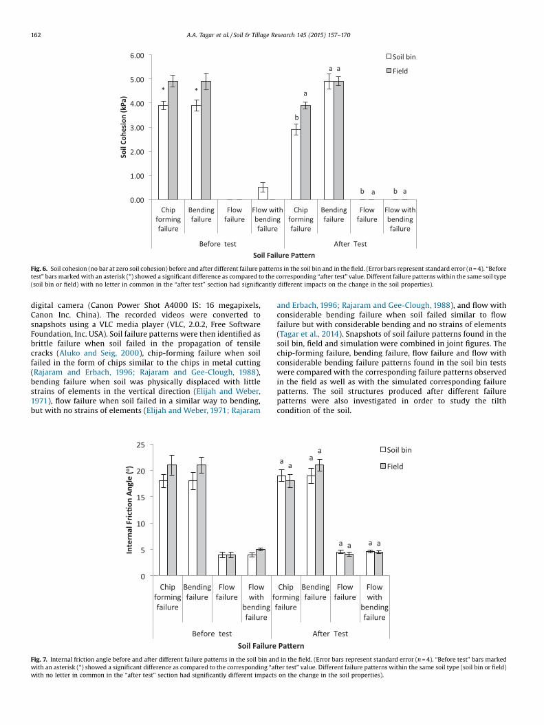
Fig. 6. Soil cohesion (no bar at zero soil cohesion) before and after different failure patterns in the soil bin and in the field. (Error bars represent standard error (n = 4). “Beforetest” bars marked with an asterisk (*) showed a significant difference as compared to the corresponding “after test” value. Different failure patterns within the same soil type(soil bin or field) with no letter in common in the “after test” section had significantly different impacts on the change in the soil properties).
162 A.A. Tagar et al. / Soil & Tillage Research 145 (2015) 157–170
digital camera (Canon Power Shot A4000 IS: 16 megapixels,Canon Inc. China). The recorded videos were converted tosnapshots using a VLC media player (VLC, 2.0.2, Free SoftwareFoundation, Inc. USA). Soil failure patterns were then identified asbrittle failure when soil failed in the propagation of tensilecracks (Aluko and Seig, 2000), chip-forming failure when soilfailed in the form of chips similar to the chips in metal cutting(Rajaram and Erbach, 1996; Rajaram and Gee-Clough, 1988),bending failure when soil was physically displaced with littlestrains of elements in the vertical direction (Elijah and Weber,1971), flow failure when soil failed in a similar way to bending,but with no strains of elements (Elijah and Weber, 1971; Rajaram
Fig. 7. Internal friction angle before and after different failure patterns in the soil bin anwith an asterisk (*) showed a significant difference as compared to the corresponding “awith no letter in common in the “after test” section had significantly different impacts
and Erbach, 1996; Rajaram and Gee-Clough, 1988), and flow withconsiderable bending failure when soil failed similar to flowfailure but with considerable bending and no strains of elements(Tagar et al., 2014). Snapshots of soil failure patterns found in thesoil bin, field and simulation were combined in joint figures. Thechip-forming failure, bending failure, flow failure and flow withconsiderable bending failure patterns found in the soil bin testswere compared with the corresponding failure patterns observedin the field as well as with the simulated corresponding failurepatterns. The soil structures produced after different failurepatterns were also investigated in order to study the tilthcondition of the soil.
d in the field. (Error bars represent standard error (n = 4). “Before test” bars markedfter test” value. Different failure patterns within the same soil type (soil bin or field)
on the change in the soil properties).

Fig. 8. Cone index before and after different failure patterns in the soil bin and in the field. (Error bars represent standard error (n = 4). “Before test” bars marked with anasterisk (*) showed a significant difference as compared to the corresponding “after test” value. Different failure patterns within the same soil type (soil bin or field) with noletter in common in the “after test” section had significantly different impacts on the change in the soil properties).
A.A. Tagar et al. / Soil & Tillage Research 145 (2015) 157–170 163
2.5. Soil physical and mechanical properties
Soil physical and mechanical properties may reveal quantitativeinformation regarding the structure of a soil after different failurepatterns. As outlined by a number of authors (e.g., Mamman andOni, 2005; Rajaram and Erbach, 1996, 1997, 1998), it isindispensable to study the physical and mechanical propertiesof soil after different failure patterns in order to better understandthe tilth condition of soil. To detect whether the structure of the
Fig. 9. Chip-forming failure pattern: (a) in the soil bin; (b) in the field (without stubble
forming failure pattern.
soil after chip-forming failure, bending failure, flow failure andflow with considerable bending failure are suitable for good tilthconditions, soil physical (rdwb) and mechanical (cohesion, internalfriction angle and cone index) properties were measured. Tomeasure the dry weight basis bulk density (rdwb) of the soil moldsin the soil bin as well as in the field, undisturbed soil core samples(50 mm diameter, 50 mm height) were collected at three differentlocations from both the soil molds in the soil bin and the test sitesin the field. The mean rdwb was then calculated using the
conditions); (c) in the field (with standing stubble conditions); (d) simulated chip-

Fig. 10. Bending failure pattern: (a) in the soil bin; (b) in the field (without stubble conditions); (c) in the field (with standing stubble conditions); (d) simulated chip-formingfailure pattern.
164 A.A. Tagar et al. / Soil & Tillage Research 145 (2015) 157–170
gravimetric method (Blake and Hartge, 1986). Soil textural classwas determined by the hydrometer method (Bouyoucos, 1927).The soil plastic limit (SMCpl) was determined as the gravimetricmoisture content at which the soil just began to crumble as it wasrolled into a thread of 3 mm in diameter (Sowers, 1965). Todetermine the soil liquid limit (SMClq), a 30� cone bearing a totalweight of about 80 g was mounted on a shaft and allowed to rest ona cup (100 mL) full of soil for 5 s. The soil moisture contentcorresponding to a penetration of 20 mm on the linear relationshipbetween soil moisture content (x-axis) and penetration (y-axis)was considered as the liquid limit (Campbell, 2001). The stickypoint of soil (SMCsp) was measured as the point at which the soilshowed maximum stickiness/adhesion to the steel spatula (Baver,1956). Organic carbon content (SOCwb) was determined using theWalkley and Black (1934) method.
2.6. Statistical analysis
Analysis of variance (ANOVA) was performed using thestatistical software R (R Core Team, 2013) to evaluate the
Fig. 11. Flow failure pattern: (a) in the soil bin; (b)
significance of the impact of different failure pattern treatmentson the magnitude of the change in soil physical and mechanicalproperties (n = 4); differences between individual treatments werecompared through pair wise t-tests using the Holm adjustment(p = 0.05). The significances of the changes in soil properties beforeand after specific tests, as well as the significance of differences inresponses between soils, were analyzed through paired t-tests(p = 0.05).
3. Results and discussion
3.1. Soil physical and mechanical properties
The physical and mechanical properties of soil bin and fieldsoils before and after different failure patterns are illustrated inFigs. 5–8. The soil cone index was significantly (p < 0.05) alteredafter all forms of failure in both soil and field conditions (with theexception of flow failure in field conditions). Soil bulk density wasonly significantly altered after chip-forming and flow failure, soilcohesion was only affected by chip-forming and flow failure in soil
in the field; (c) simulated flow failure pattern.

Fig. 12. Flow with bending failure pattern: (a) in the soil bin; (b) in the field; (c) simulated flow failure pattern.
A.A. Tagar et al. / Soil & Tillage Research 145 (2015) 157–170 165
bin conditions. On the other hand, the internal friction anglewas not significantly altered in any of the tests. The rdwb after(vs. before) chip-forming failure decreased from 1.4 to 1.32 Mg m�3
in the soil bin and from 1.4 to 1.31 Mg m�3in the field. After(vs. before) flow failure pattern rdwb decreased from 1.4 to1.31 Mg m�3 in the soil bin and from 1.4 to 1.33 Mg m�3 in thefield. However, changes in rdwb for bending and flow withbending failure patterns were statistically non-significant(Fig. 5).
These results indicate that the rdwb after different failurepatterns was not conducive to good tilth. Generally, the growth ofroots is limited by increasing soil bulk density and excessive soilresistance due to insufficient aeration or saturation by water
Fig. 13. Chip-forming failure: (a) stress at 0.02
(Greacen and Sands, 1980), and Masle and Passioura (1987)concluded that both high and low bulk densities can result inreduced crop establishment. Higher soil bulk density can reducesoil porosity, water holding capacity and root growth (Gebauer andMartinková, 2005). Tirado-Corbalá and Slater (2010) concludedthat trees planted on sandy clay loam exhibited greatest dry rootweight at the bulk density of 1.2 Mg m�3, while bulk densities inthe range of 1.4–2.2 Mg m�3 can limit the growth of roots(Patterson, 1977; Alberty et al., 1984; Randrup, 1998). An idealsoil contains about 50% solid particles and 50% pore space byvolume (Hillel, 1982). As such, despite the decreases in bulkdensities observed, none of the treatments reached ideal bulkdensity conditions.
s, (b) stress at 0.06 s and (c) stress at 0.1 s.

166 A.A. Tagar et al. / Soil & Tillage Research 145 (2015) 157–170
Soil cohesion slightly decreased between before and after chip-forming failure, from 3.9 to 2.9 kPa in the soil bin and from 4.9 to3.9 kPa in the field. Soil cohesion increased slightly from 3.9 to4.9 kPa in the soil bin after bending failure, but remained constantat 4.9 kPa in the field. Changes in soil cohesion after flow failurewere negligible (Fig. 6). Changes in the internal friction angle, onthe other hand, were statistically non-significant after all tests(Fig. 7).
The soil cone index decreased from 106 kPa to 34.78 kPa in thesoil bin and from 104 kPa to 31 kPa in the field after chip-formingfailure, and, after bending failure, from 106 kPa to 40 kPa in thesoil bin and from 104 kPa to 38 kPa in the field. However, afterflow failure pattern it decreased but slightly from 13 kPa to8.22 kPa in the soil bin, while changes in the field were notsignificant. In the case of flow with considerable bending failure,the cone index also decreased significantly, though to a lesserextent: from 15 kPa to 6 kPa in the soil bin and from 13 kPa to6 kPa in the field (Fig. 8).
The change in cohesion and internal friction angle were non-significant (p > 0.05) in soil bin and field tests for both chip-forming and bending failure, remaining constant or decreasingslightly after the former and increasing slightly after the latter. Thismay have occurred because, in chip-forming failure, the operatingdepth (30 mm) and rake angle (15�) were small, so that the soilfailed in the form of chips, while in bending failure the operatingdepths (50 mm and 70 mm) and rake angles (30� and 45�) werelarge, so that the soil did not fail but rather molded. This isconsistent with Keller and Dexter (2012), who mentioned that atthe plastic limit, each soil particle is surrounded by a film of waterthat causes them to slide over each other, so that the soil thereforeundergoes plastic deformation. However, those properties
Fig. 14. Bending failure: (a) stress at 0.02 s, (
decreased significantly after flow failure and flow with consider-able bending failure patterns in both soil bin and field tests. This isattributable that in flow failure and flow with considerablebending failure patterns, all pores are filled by water and the soil iscapable of viscous flow (Keller and Dexter, 2012).
The soil cone index decreased significantly after nearly all typesof soil failure patterns and conditions, potentially affecting soilworkability. Shaw et al. (1942) and Busscher et al. (1997)concluded that soil moisture content is the dominant factordetermining cone index, with lower moisture levels leading toincreased cone indices, consistent with Henderson et al. (1988),who concluded that the cone index increased exponentially withthe reductions in moisture content. According to Adeniran andBabatunde (2010), the high moisture content weakens soilmolecular bonds, thereby decreasing the cohesive forces of thesoil particles. This leads to cultivation practices becoming difficult,leading to high slippage, sinkage and smearing of machinery andloss of trafficability.
For efficient soil cultivation with a SMC beyond the criticalvalue (23.72%), the soil needs to be drained before cultivation.Utomo and Dexter (1981) concluded that at high SMC levels,soils have relatively little strength and should not be consideredsuitable for tillage. This is supported by Bourma (1969),Kuipers (1982) and Keller and Dexter (2012) who concluded thatif tillage is performed when soils are too wet (above the plasticlimit), they lose their aggregate structure through the moldingprocesses, creating unfavorable soil conditions. This is consistentwith Dexter and Bird (2001) who concluded that when soil is tilledat a SMC exceeding the SMCpl, the soil will deform plasticallyand thus lose its structure. Consequently, a soil with goodworkability usually has a SMCfc that is lower than its SMCpl
b) stress at 0.06 s and (c) stress at 0.1 s.

A.A. Tagar et al. / Soil & Tillage Research 145 (2015) 157–170 167
(Barzegar et al., 2004; Keller and Dexter, 2012; Müller et al., 2003;Ojeniyi and Dexter, 1979; Utomo and Dexter, 1981; Watts andDexter, 1998).
3.2. Comparison of simulated failure patterns with soil bin and thefield
In the FEM simulation, the chip-forming failure pattern wasobserved at a 30 mm operating depth and 15� rake angle, asobserved for both the soil bin and field tests at the plastic limit(Fig. 9a–c), with the size of the chips being equal to the operatingwidth of the tine. In contrast, Rajaram (1987) and Rajaram andErbach (1996) observed this type of failure at an SMC of 28.6%(slightly above the SMCpl). Bending failure was observed at 50 mmand 70 mm depths of operation and 30� and 45� rake angles in thesimulation, which matched that of the soil bin; however, thestrains of elements seen with the soil bin were not present in thesimulated failure pattern, while bending was not found in the field(Fig. 10a–c). This observation concurs with Elijah and Weber(1971), who found bending failure with little strains of elements athigh moisture contents in a soil bin, but not in the field. Similartypes of failure patterns were observed in the field with standingstubble conditions, but the failure patterns were found to beaffected by the standing stubble and roots in the field (Figs. 9d and10 d). The chip was 62 mm wide and 30 mm thick in the soil bin,while in the field the chip was 71 mm wide and 30 mm thick.However, the bending failure was 106 mm wide and 53 mm thick inthe soil bin, while in the field the bending failure was 112 mm wideand 54 mm thick.
At the liquid limit, flow failure was observed at all operatingdepths (30 mm, 50 mm and 70 mm) and rake angles (15�, 30� and45�) in the simulation, which closely followed that in the soil bin or
Fig. 15. Flow failure: (a) stress at 0.02 s, (b
field (Fig. 11a–c), although the roots of the stubble in the field didaffect the soil flow failure pattern, giving it the appearance of chip-forming failure. Such a flow-type failure pattern was also observedby Wang (1991) at SMC levels of 44% and 52%, and by Rajaram andGee-Clough (1988) at 42% in Bangkok clay soils. In contrast, Wangand Gee-Clough (1993) found brittle failure and shear failurepatterns at 44% moisture content. However, our study found thatflow failure is clearly related to the SMClq of the soil. Flow failurewas 43 mm wide and 32 mm thick in the soil bin, while in the fieldit was 57 mm wide and 30 mm thick.
At SMCsp, the flow with considerable bending as simulated for50 mm and 70 mm operating depths and 30� and 45� rake anglesclosely matched that seen in the soil bin and to a lesser extent thatseen in the field (Fig. 12a–c), where bending was slightly less thanthat observed in the soil bin. This difference may be due to the factthat, though the soil has a maximum stickiness at the sticky pointof soil, it has a greater support and a larger cross-sectional area inthe field (as in the case of soil bin). The flow failure (Makanga et al.,1996, 2010; Rajaram and Gee-Clough, 1988; Stafford, 1981; Wang,1991) and bending failure patterns (Elijah and Weber, 1971) havealready been explored in the literature; however, flow failure withconsiderable bending and no strains of elements at the sticky pointhas not been reported earlier. In the soil bin, the flow withconsiderable bending failure was 108 mm wide and 55 mm thick,while in the field the flow with bending failure was 105 mm wideand 51 mm thick.
Figs. 13–16 show that the minimum and maximum stresses inchip-forming, bending, flow and flow with bending failure patternswere highly variable with time, with maximum stresses of1670 kPa at 0.02 s, 7150 kPa at 0.06 s and 7693 kPa at 0.1 s in theflow with bending failure pattern, while the minimum stresseswere of 0.32 kPa at 0.02 s, 1.83 kPa at 0.06 s and 12.98 kPa at 0.1 s.
) stress at 0.06 s and (c) stress at 0.1 s.
Fig. 16. Flow with bending failure: (a) stress at 0.02 s, (b) stress at 0.06 s and (c) stress at 0.1 s.
168 A.A. Tagar et al. / Soil & Tillage Research 145 (2015) 157–170
Thus, it is evident that the simulated chip-forming failure andflow failure patterns correlated well with the failure patternsfound in the soil bin and in the field, while bending failure and flowwith considerable bending failure correlated well with the soil binonly, because bending failure is not observed under fieldconditions at the plastic limit (field soil physical property testsfor “bending failure” were obtained from failure at the samemoisture content and rake angle and depth that caused bendingfailure in the soil bin). It is anticipated that if at the SMCpl theoperating parameters of the tool are small (�30 mm and �15�),then a smaller portion of the tool (30 mm) will enter and cut alesser depth of soil in the form of chips without bending, becausethe remaining soil, having a larger cross-sectional area withrespect to the operating parameters of tool, has more support.Comparatively, at the same SMCpl, if the tool's operatingparameters are large (�30 mm and �15�), a larger portion of thetool enters the soil, the tip of the tool cuts the soil, and theremaining part of the tool creates bending. However, in similarfield conditions, though the operating parameters of the tool arelarge, the bending is not created, because the soil has a greatersupport and a larger cross-sectional area (resulting in chip-formingfailure). The strains of elements in the vertical direction were largerand deeper in the field, possibly due to the roots of the stubble.However, slight bending was experienced at the SMCsp of the soil.This is consistent with Gee-Clough et al. (1994), who conducted astudy to investigate the use of FEM to predict wet clay soil responseto a wide tine and concluded that the soil failure patterns weresimilar to those observed in soil bin experiments. It is evident thatFEM provided good simulation of soil failure patterns; however,soil failure patterns correlated better with those found in soil bintests as compared to the field tests in the presence of standing
stubbles and their roots. This is consistent with Theuer (2011), whostated that in real field situations, a complex system of crop plants,clods, roots, and mixed terrain (soil mixed with stones etc.) rendersthe simulation more complicated, making it nearly impossible toaccount for all of these influencing factors. Karmakar andKushwaha (2006) also confirm the limitation of FEM for dynamiceffects in the simulation of soil–tool interactions. It is suggestedthat in future studies, other numerical methods (e.g., discreteelement method and computational fluid dynamics) should also beexplored for the more accurate simulation of field conditions.
4. Conclusions
In this study, the ability of FEM to simulate soil failure patternsat the plastic and liquid limits of soil in both laboratory (soil bin)and field conditions was evaluated. In general, FEM providedacceptable simulation of soil failure patterns; however, thesimulation results correlated better with soil failure patternsfound in soil bin tests as compared to the field tests in the presenceof standing stubbles as well as their roots. This study has alsoshown that there is a direct relationship between soil failurepatterns and the consistency limits of the soil both in the soil bin aswell as in the field; however, bending failure was not properlyobserved in the field. Of the soil properties tested, only the soilcone index was consistently changed by all types of soil failurepatterns; bulk density was only affected by chip and flow failureand soil cohesion was only affected by chip and bending failure insoil bin conditions, while the internal friction angle was notaffected by any failure pattern in either soil bin or field conditions.This study has also shown that the soil structures produced after

A.A. Tagar et al. / Soil & Tillage Research 145 (2015) 157–170 169
different failure patterns at the plastic and liquid limits of soilswere not conducive to good tilth.
It is suggested that future research investigate the stickyconsistency limit of soils, which occurs at lower moisture contentcompared to plastic limit and liquid limit as well as sticky point ofsoil, which may provide better soil physical conditions ascompared to plastic and liquid consistency limits. Furtherinvestigation into the use of other numerical methods to accuratelysimulate soil failure patterns found in the field tests may also be offuture interest.
Acknowledgements
This study was funded by the National Science Foundation ofChina (Grant Nos. 41371238; 51275250) and the Priority AcademicProgram Development of Jiangsu Higher Education Institutions(PAPD). Partial funding was also provided by an NSERC DiscoveryGrant, as well as a CFI grant, held by Jan Adamowski.
References
Abo Al-Kheer, A., Aoues, Y., Eid M., El-Hami, A., 2011.Integrating optimization andreliability tools into the design of agricultural machines. In: 20e Congre‘sFrancSais de Me canique BesancS on, 29 aou t au 2 septembre 2011. AFM, Maisonde la Me canique, Courbevoie, France. (accessed 29.04.2013) http://documents.irevues.inist.fr/bitstream/handle/2042/46919/cfm2011_327.pdf.
Abo Al-Kheer, A., Kharmanda, M.G., A. El Hami, A., Mouazen, A.M., 2011b. Estimatingthe variability of tillage forces on a chisel plough shank by modeling thevariability of tillage system parameters. Comput. Electron. Agr. 78 (1), 61–70.
Adeniran, K.A., Babatunde, O.O., 2010. Investigation of wetland soil propertiesaffecting optimum soil cultivation. J. Eng. Sci. Technol. Rev. 3 (1), 23–26.
Alberty, C.A., Pellet, H.M., Taylor, D.H., 1984. Characterization of soil compaction atconstruction sites and woody plant response. J. Environ. Hortic. 2, 48–53.
Aluko, O.B., 2008. Finite element aided brittle fracture force estimation during two-dimensional soil cutting. Int. Agrophys. 22, 5–15.
Aluko, O.B., Chandler, H.W., 2004. Characterization and modeling of brittle fracturein two dimensional soil cutting. Biosys. Engng. 88 (3), 369–381.
Aluko, O.B., Seig, D.A., 2000. An experimental investigation of the characteristics ofand conditions for brittle failure in two-dimensional soil cutting. Soil Till. Res.57 (3), 143–157.
Barnes, K.K., Bockhop, C.W., 1960. McLeod H E. Similitude studies of tillageimplement forces. Agric. Eng. 41 (1), 32–37.
Barzegar, A.R., Hashemi, A.M., Herbert, S.J., Asoodar, M.A., 2004. Interactive effects oftillage system and soil water content on aggregate size distribution for seedbedpreparation in Fluvisols in southwest Iran. Soil Till. Res. 78, 45–52.
Baver, L.D., 1956. Soil Physics. John Wiley & Sons, New York.Blake, G.R., Hartge, k.H., 1986. Bulk density. In: Klute, A. (Ed.), Methods of Soil
Analysis. Part 1. Physical and Mineralogical Methods. American Society ofAgronomy and Soil Science Society of America, Madison, pp. 363–376.
Bourma, J., 1969. Micro-structure and stability of two sandy loam soils withdifferent soil managements. Agricultural Research Report 724. Pudoc,Wageningen.
Bouyoucos, G.J., 1927. The hydrometer as a new method for the mechanical analysisof soils. Soil Sci. 23 (5), 343–353.
Busscher, W.J., Bauer, P.J., Camp, C.R., Sojka, R.E., 1997. Correction of cone index forsoil water content differences in a coastal plain soil. Soil Till. Res. 43 (3–4), 205–217.
Campbell, D.J., 2001. Liquid and plastic limits. In: Smith, K.A., Mullins, C. (Eds.), Soiland Environmental Analysis: Physical Methods. Marcel Dekker, Inc., New York,pp. 349–376.
Chandler, H.W., 1984. The use of non-linear fracture mechanics to study the fractureproperties of soils. J. Agric. Eng. Res. 29 (4), 321–327.
Chi, L., Kushwaha, R.L., 1987. Three-dimensional finite element analysis of soilfailure under a narrow tillage tool. ASAE Paper No. 88-1582. St. Joseph, MI, USA.
Chi, L., Kushwaha, R.L., 1989. Finite element analysis of forces on a plane soil cuttingblade. Can. Agric. Eng. 31, 135–140.
Coetzee, C.J., Els, D.N.J., 2009. Calibration of granular material parameters for DEMmodelling and numerical verification by blade–granular material interaction. J.Terramechanics 46, 15–26.
Coleman, G.E., Perumpral, J.V., 1974. The finite element analysis of soil compaction.Trans. ASAE 17, 856–860.
Dexter, A., Bird, N.R.A., 2001. Methods for predicting the optimum and range of soilwater contents for tillage based on the water retention curve. Soil Till. Res. 57(4), 203–212.
Elijah, D.L., Weber, J.A.,1971. Soil failure and pressure patterns for flat cutting blades.Trans. ASAE 14 (4), 781–785.
Gebauer, R., Martinková, M., 2005. Effects of pressure on the root systems of Norwayspruce plants (Piceaabies [L.] Karst). J. Forest Sci. 51, 268–275.
Gee-Clough, D., Wang, J., Kanok-Nukulchai, W., 1994. Deformation and failure in wetclay soil: part 3, finite element analysis of cutting of wet clay by tines. J. Agric.Eng. Res. 58 (2), 121–131.
Greacen, E.L., Sands, R., 1980. Compaction of forest soils: a review. Aust. J. Soil Res.18, 163–189.
Grote, K.H., Feldhusen, J., 2005. Dubbel–Taschenbuch fur den maschinenbau, 21sted. Springer, Berlin/Heidelberg.
Hatibu, N., 1987. The mechanical behaviour of brittle agricultural soils. Ph.D. Thesis.Department of Agricultural Engineering. University of Newcastle upon Tyne,Newcastle upon Tyne, UK.
Hemmat, A., Khorsandy, A., Shafaie, V., 2012. Soil failure mode in front of a multiple-tip horizontally operated penetrometer. Turk. J. Agric. For. 36 (2012), 476–485.
Henderson, C., Levett, A., Lisle, D., 1988. The effects of soil water content and bulkdensity on the compatibility and soil penetration resistance of some WesternAustralian sandy soils. Aust. J. Soil Res. 26 (2), 391–400.
Hillel, D., 1982. Introduction to Soil Physics. Academic Press, Inc., Orlando, FL, USA.Jafari, R., TavakoliHashjin, T., Minaee, S., Raoufat, M.H., 2006. Large deformation
modeling in soil?tillage tool interaction using advanced 3D nonlinear finiteelement approach. In: AM, Madureira (Eds.), Proc. 6th WSEAS Int. Conf. onSimulation, Modeling and Optimization, September 22–24, 2006. WorldScientific and Engineering Academy and Society, Lisbon, Portugal, pp. 246–251.
Jayasuriya, H.P.W., Salokhe, V.M., 2001. A review of soil-tine models for a range ofsoil conditions. J Agric. Eng. Res. 79 (1), 1–13.
Karmakar, S., Kushwaha, R., 2006. Dynamic modeling of soil–tool interaction: anoverview from a fluid flow perspective. J. Terramechanics 43, 411–425.
Keller, T., Dexter, A.R., 2012. Plastic limits of agricultural soils as functions of soiltexture and organic matter content. Soil Res. 50 (1), 7–17.
Kuipers, H., 1982. Processes in soil physical degradation in mechanized agriculture.In: Boels, C.D., Davies, B.D., Johnston, A.E. (Eds.), Soil Degradation. Galkema,Rotterdam.
Lewis, B.A., 2004. Evaluation of LS-DYNA Soil Material Model 147. Report No. FHWA-HRT-04-094. Federal Highway Administration.
Li, M., Zhang, H., 2012. Hydrophobicity and carbonation treatment of earthenmonuments in humid weather condition. Sci. China Tech. Sci. 55 (8), 2313–2320.
Liu-Yan, HouZhi-Min 1985. Three dimensional nonlinear finite element analysis ofsoil cutting by narrow blades. Proc. Int. Conf. Soil Dynamics, Auburn, AL, USA, 2,322-337.
Liu, J., Chen, Y., Lobb, D.A., Kushwaha, R.L., 2007. Soil-straw-tillage tool interaction:field and soil bin study. Can. Biosyst. Eng. 49, 2.1–2.6.
Makanga, J.T., Salokhe, V.M., Gee-Clough, D., 1996. Effect of tine rake angle andaspect ratio on soil failure patterns in dry loam soil. J. Terramechanics 33 (5),233–252.
Makanga, J.T., Salokhe, V.M., Gee-Clough, D., 1997. Effect of tine rake angle andaspect ratio on soil reactions in dry loam soil. J. Terramechanics 34 (4), 235–250.
Makanga, J.T., Salokhe, V.M., Gee-Clough, D., 2010. Deformation and forcecharacteristics caused by inclined tines in loam soil with moisture contentbelow liquid limit. J. Agric. Sci. Technol. 12 (2), 181–205.
Mamman, E., Oni K.C., 2005. Draught performance of range of model chiselfurrowers. CIGR Ejournal.PM 05 003. 7, 1–17. http://hdl.handle.net/1813/10474(accessed 3.07.13.).
Masle, J., Passioura, J.B., 1987. The effect of soil strength on the growth of youngwheat plants. Aust. J. Plant Physiol. 14, 643–656.
McKyes, E., Desir, F.L., 1984. Prediction and field measurement of tillage tool draftforces and efficiency in cohesive soils. Soil Till. Res. 4 (4), 459–470.
Müller, L., Schindler, U., Fausey, N.R., Lal, R., 2003. Comparison of methods forestimating maximum soil water content for optimum workability. Soil Till. Res.72 (1), 9–20.
Ojeniyi, S.O., Dexter, A.R., 1979. Soil factors affecting the macrostructures producedby tillage. Trans. Am. Soc. Agric. Eng. 22, 339–343.
Patterson, J., 1977. Soil compaction-effects on urban vegetation. J. Arboric. 3, 161–167.
R Core Team, 2013. R: A language and environment for statistical computing. RFoundation for Statistical Computing, Vienna, Austria. http://www.R-project.org/.
Rajaram, G., 1987. Force-time behavior of tine implements. M. Eng. Thesis No. AE-87-14. Asian Institute of Technology, Bangkok, Thailand.
Rajaram, G., 1990. Collapse failure in dry clay soils caused by tine implements. J.Terramechanics 27 (2), 6–78.
Rajaram, G., Erbach, D.C., 1996. Soil failure by shear versus soil modification bytillage: a review. J. Terramechanics 33 (6), 265–272.
Rajaram, G., Erbach, D.C., 1997. Hysteresis in soil mechanical behavior. J.Terramechanics 34 (4), 251–259.
Rajaram, G., Erbach, D.C.,1998. Drying stress effect on mechanical behavior of a clay-loam soil. Soil Till. Res. 49 (1–2), 147–158.
Rajaram, G., Erbach, D.C., 1999. Effect of wetting and drying on soil physicalproperties. J. Terramechanics 36 (1), 39–49.
Rajaram, G., Gee-Clough, D., 1988. Force–distance behavior of tine implements. J.Agric. Eng. Res. 41 (2), 81–98.
Randrup, T.B., 1998. Soil compaction on construction sites. In: Neely, D., Watson, G.W. (Eds.), The landscape below ground II: Proceedings of an InternationalWorkshop on Tree Root Development in Urban Soils. International Society ofArboriculture, Champaign, IL, pp. 146–153.
Raper, R.L., Erbach, D.C., 1990. Prediction of soil stresses using the finite elementmethod. Trans. ASAE 33 (3), 725–730.

170 A.A. Tagar et al. / Soil & Tillage Research 145 (2015) 157–170
Shahab Davoudi, Reza Alimardani, Alireza Keyhani, Reza Atarnejad, 2008. A twodimensional finite element analysis of a plane tillage tool in soil using a non-linear elasto-plastic model. Amer-Eurasian J. Agric. Environ. Sci. 3 (3), 498–505.
Shaw, Haise, H.R., Farnsworth, R.B., 1942. Four years’ experience with a soilpenetrometer. Soil Sci. Soc. Am. Proc. 7, 48–55.
Shmulevich, I., 2010. State of the art modeling of soil–tillage interaction usingdiscrete element method. Soil Till. Res. 111, 41–53.
Sowers, G.F.,1965. ConsistencyIn: Black, C.A., Evan, D.D., White, J.L., Ensimenger, L.E.,Clark, F.E. (Eds.), Methods of Soil Analysis (Part 1), Physical and MineralogicalProperties, Including Statistics of Measurements and Sampling AgronomyMonograph 9. American Society of Agronomy, Madison, pp. 391–399. . c31http://dx.doi.org/10.2134/agronmonogr9.1.
Stafford, J.V., 1979a. The performance of a rigid tine in relation to soil properties andspeed. J. Agric. Eng. Res. 24 (1), 41–56.
Stafford, J.V.,1979b. A versatile high-speed soil tank for studying soil and implementinteraction. J. Agric. Eng. Res. 24, 57–66.
Stafford, J.V., 1981. An application of critical state soil mechanics. The performanceof rigid tines. J. Agric. Eng. Res. 26 (5), 387–401.
Tagar, A.A., Ji Changing, Ding Qishuo, Jan Adamowski, Chandio, F.A., Mari, I.A., 2014.Soil failure patterns and draft as influenced by consistency limits: an evaluationof the remolded soil cutting test. Soil Till. Res. 137, 58–66.
Theuer, J., 2011. Finite element modelling of the interaction between flexible tinesand soil for mechanical weeding. Thesis submitted in the partial fulfilment of
the requirements for the degree of MSc by Research. Cranfield University.https://dspace.lib.cranfield.ac.uk/bitstream/1826/7307/1/Jan_Theuer_The-sis_2011.pdf.
Tirado-Corbalá, R., Slater, B.K., 2010. Soil compaction effects on the establishment ofthree tropical tree species. Arboric. Urb. Forest. 36 (4), 164–170.
USDA, 1999. Soil Quality Test Kit Guide. USDA Soil Quality Institute, Washington, D.C.
Utomo, W.H., Dexter, A.R., 1981. Effect of ageing on compression resistance andwater stability of soil aggregates disturbed by tillage. Soil Till. Res. 1, 127–137.
Walkley, A., Black, I.A., 1934. An examination of the Degtjareff method fordetermining organic carbon in soils: effect of variations in digestion conditionsand of inorganic soil constituents. Soil Sci. 63, 251–263.
Wang, J., 1991. Stress-strain relationship in wet clay soil and some applications. AITD. Eng. Dissertation No. AE -91-1. Asian Institute of Technology, Bangkok,Thailand.
Wang, J., Gee-Clough, D., 1993. Deformation and failure in wet clay soil, Part 2: soilbin experiments. J. Agric. Engg. Res. 54 (1), 57–66.
Watts, C.W., Dexter, A.R.,1998. Soil friability: theory, measurement and the effects ofmanagement and organic carbon content. Eur. J. Soil Sci. 49, 73–84.
Wegscheid, E.L., Myers, H.A., 1967. Soil bin instrumentation. Agric. Eng. 48 (8),442–445.
Yong, R.N., Hanna, A.W., 1977. Finite element analysis of plane soil cutting. J.Terramechanics 14 (3), 103–125.