soil dynamics and earthquake engineering - ntuassi.civil.ntua.gr/downloads/journals/2012_sdee... ·...
TRANSCRIPT
Soil Dynamics and Earthquake Engineering 40 (2012) 15–33
Contents lists available at SciVerse ScienceDirect
Soil Dynamics and Earthquake Engineering
0267-72
http://d
n Corr
E-m
journal homepage: www.elsevier.com/locate/soildyn
Rocking response of SDOF systems on shallow improved sand:An experimental study
Ioannis Anastasopoulos n, Rallis Kourkoulis, Fani Gelagoti, Efthymios Papadopoulos
School of Civil Engineering, National Technical University of Athens, Greece
a r t i c l e i n f o
Article history:
Received 7 August 2011
Received in revised form
3 April 2012
Accepted 18 April 2012
61/$ - see front matter & 2012 Elsevier Ltd. A
x.doi.org/10.1016/j.soildyn.2012.04.006
esponding author. Tel.: þ30 2107723383; fa
ail address: [email protected] (I. Anastasop
a b s t r a c t
Recent studies have highlighted the potential advantages of allowing inelastic foundation response
during strong seismic shaking. Such an alternative seismic design philosophy, in which soil failure is
used as a ‘‘fuse’’ for the superstructure has recently been proposed, in the form of ‘‘rocking isolation’’.
Within this context, foundation rocking may be desirable as a means of bounding the inertia forces
transmitted onto the superstructure, but incorporates the peril of unacceptable settlements in case of a
low static factor of safety FSv. Hence, to ensure that rocking is materialized through uplifting rather
than sinking, an adequately large FSv is required. Although this is feasible in theory, soil properties are
not always well-known in engineering practice. However, since rocking-induced soil yielding is only
mobilized within a shallow layer underneath the footing, ‘‘shallow soil improvement’’ is considered as
an alternative approach to release the design from the jeopardy of unforeseen inadequate FSv. For this
purpose, this paper studies the rocking response of relatively slender SDOF structures (h/B ratio equals
3 and rocking dominates over sliding), with emphasis on the effectiveness of shallow soil improvement
stretching to various depths below the foundation. A series of reduced-scale monotonic and slow-cyclic
pushover tests are conducted on SDOF systems lying on a square surface foundation. It is shown that
shallow soil improvement may, indeed, be quite effective provided that its depth is equal to the width
of the foundation. For lightly-loaded systems, an even shallower soil improvement may also be
considered effective, depending on design requirements. The effectiveness of shallow soil improvement
is ameliorated with the increase of cyclic rotation amplitude, and with repeating cycles of loading.
& 2012 Elsevier Ltd. All rights reserved.
1. Introduction
Contemporary earthquake engineering norms aim to alleviatethe destruction and avert collapse caused by earthquakes, byallowing ductility-controlled inelastic behavior of the superstruc-ture. Design principles aim at guiding failure to above-groundstructural members, prohibiting mobilization of foundation bear-ing-capacity, uplifting and/or sliding (e.g., [43]). This is typicallyachieved by imposing over-strength factors and conservativefactors of safety against all such possible ‘‘failure’’ modes, whichin turn generates substantial ductility requirements on above-ground structural elements. Yet, thanks to the cyclic and kine-matic nature of seismic shaking, such mobilization does notnecessarily lead to collapse. In fact, recent research suggests thatsoil compliance and subsequent soil–foundation plastic yieldingmay be beneficial, and should be considered in analysis andperhaps allowed in design (e.g., [38,40,41,22,18,29]).
ll rights reserved.
x: þ30 2107722405.
oulos).
In this framework, recent studies have investigated the non-linear response of soil–foundation–structure systems analytically,by means of sophisticated Winkler-based models [49,34,12,28,1,2,44], advanced macro-element modeling [36,42,31,13,26,10,11,16], and direct numerical methods (finite elements orfinite differences) where both the structure and the foundation–soil system are modeled together [48,9,47,25,6]; and experimen-tally, by means of large-scale cyclic pushover testing [35,15],centrifuge model testing [30,18–20], or reduced-scale cyclicpushover and shaking table testing [39,46,14].
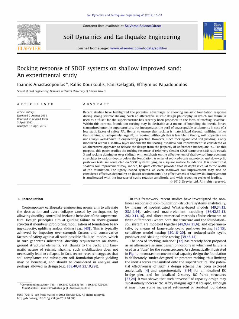
The idea of ‘‘rocking isolation’’ [32] has recently been proposedas an alternative seismic design philosophy in which soil failure isused as a ‘‘fuse’’ for the superstructure. As schematically illustratedin Fig. 1, in contrast to conventional capacity design the foundationis deliberately ‘‘under-designed’’ to promote rocking, thus limitingthe inertia forces transmitted onto the superstructure. The poten-tial effectiveness of such a design scheme has been exploredanalytically [4] and experimentally [3,14] for an idealized RCbridge pier, and for idealized 2-storey RC frame structures[23,24]. It was shown that such ‘‘reversal’’ of capacity design maysubstantially increase the safety margins against collapse, althoughit may incur some increased settlement or residual foundation
Superstructuredamage in the formof plastic “hinging” Practically elastic
foundation response
Conventional Capacity Design
Overdesigned footing
Rocking Isolation Design
Strongly nonlinearfoundation response :
rotation and settlement
Practically elasticSuperstructure
response
Smaller footing
Fig. 1. Conventional capacity design versus rocking isolation. While in a conventionally designed system failure is guided to the superstructure, in a rocking-isolated
system the moment capacity of the foundation is fully mobilized to promote rocking and protect the superstructure, at the cost of foundation rotation and settlement.
Q
N
M
Large FSV:Uplifting-dominated response
Limited soilplastification Extensive
Soil Yielding
Q
Low FSV:Sinking-dominated response
N
M
Fig. 2. Rocking response of a surface foundation subjected to combined (M, Q, N) loading, for: (a) relatively large FSv, where the response is uplifting-dominated and
settlement is minimized; and (b) relatively low FSv, where the bearing capacity failure mechanism is mobilized and the response is sinking-dominated, leading to
accumulation of substantial settlement.
I. Anastasopoulos et al. / Soil Dynamics and Earthquake Engineering 40 (2012) 15–3316
rotation. Provided that the safety factor against static (vertical)loads FSv is maintained adequately large, such kinematically-induced distortion may be maintained within tolerable limits.As sketched in Fig. 2, when FSv is relatively large, the foundationwill respond to strong seismic shaking mainly through uplifting,not accumulating substantial settlement. In stark contrast, in caseof lower FSV excessive soil yielding will take place and the responsewill be sinking-dominated, leading to substantial accumulation ofsettlement and permanent rotation, possibly unacceptable for thedesign. Evidently, ensuring an adequately large FSV in order topromote uplifting-dominated response greatly depends on theexact soil properties which may not always be accurately known.
In an effort to overcome this obstacle, this paper investigatesthe potential effectiveness of shallow soil improvement, a conceptcommonly applicable in geotechnical engineering as a means toincrease soil strength and reduce settlements. The competence ofshallow mitigation stems from the very nature of foundationrocking, which for large FSV indeed mobilizes only a shallow stressbulb within the soil. Fig. 3 plots the distribution of vertical stressesand the corresponding plastic strains for a lightly loaded (FSv¼10)and a heavily loaded (FSv¼2) single degree of freedom (SDOF)system subjected to monotonic M–Q loading, computed throughnonlinear finite element analysis (as described in [6]). In the firstcase (FSv¼10), the soil below a shallow depth z equal to half thewidth of the footing (z/B40.5) is not affected by the rocking-induced vertical stresses, with plastic deformation being clearlyshallower. In the latter case, the rocking mechanism is deeper, withthe vertical stresses being substantially affected at depths z/Br1,and plastic deformation evident within a zone of depth z/Br0.5.
Motivated by this behaviour, a series of reduced-scale (1 g)monotonic and slow-cyclic pushover tests were conducted in the
Laboratory of Soil mechanics of the National Technical Universityof Athens (NTUA) in order to investigate:
(a)
the rocking response of slender SDOF structures under mono-tonic and slow-cyclic loading, driving them well into theirmetaplastic regime (i.e., the post-peak behaviour, well beyondtheir moment capacity), and(b)
the effectiveness of shallow soil improvement stretching tovarious depths below the foundation. The role of FSV and ofthe applied loading protocol is explored parametrically.It is understandable, that the results produced herein pertainto surface foundations or those shallow embedded; for deeperdepths of embedment the results may diverge substantially fromthe ones shown herein.
2. Problem definition and experimental methodology
A slender h/B¼3 single degree of freedom (SDOF) systemsupported on a surface square foundation of width B is studied,considered representative of a relatively slender bridge pier(of prototype dimensions B¼6 m and h¼18 m, assuming a scaleof 1:40) or a RC column of a frame structure (of prototypedimensions B¼1.5 m and h¼4.5 m, assuming a scale of 1:10).Model properties (geometry, mass, stiffness, etc.) were scaled downaccording to relevant scaling laws [33]. The investigated modelconfigurations are schematically illustrated in Fig. 4. In all casesexamined, to focus on foundation performance the superstructure isassumed rigid and elastic. Two superstructure systems are studied,both lying on square foundations: System A refers to a lightly loaded

z/B = 0.5
z/B = 1
z/B = 0.5
z/B = 1
z/B = 0.5
z/B = 1
z/B = 0.5
z/B = 1
Lightly loaded footingx = N/Nult = 0.1 (FSv = 10)
Heavily loaded footingx = N/Nult = 0.5 (FSv = 2)
Fig. 3. Illustration of the shallow nature of the rocking mechanism. Numerical simulation of a lightly-loaded (FSv ¼10) and a heavily-loaded (FSv ¼2) footing : (a) contours
of vertical stresses and (b) plastic strain. In the first case, the soil at depth z/B4 0.5 is clearly not affected and plastic deformation is even shallower. In the latter case, the
rocking mechanism is deeper, with the vertical stresses being substantially affected at depths z/Br1, and plastic deformation being contained at z/Br0.5.
I. Anastasopoulos et al. / Soil Dynamics and Earthquake Engineering 40 (2012) 15–33 17
structure (relatively large FSv), while System B is representative of aheavily loaded structure (relatively low FSv). The two systems wereselected to model distinctly different foundation performance, fromuplifting-dominated (System A) to sinking-dominated response(System B). The two systems were founded in three different soilconditions: (a) dense sand (Dr¼93%), representing the reference caseof ideal soil conditions; (b) medium sand (Dr¼65%) for System A andloose sand (Dr¼45%) for System B, representing poor soil conditions;and (c) soil improvement by means of a shallow ‘‘crust’’ of densesand, of varying depth z/B¼0.25–1. A full width improvement layerwas used in the experiments to facilitate preparation of the sandspecimen. Nevertheless, in reality the zone of improvement can be ofmuch smaller width. Although the width of the improvement has notbeen investigated herein, based on numerical analysis results thenecessary width of improvement can be of the order of 3B.
2.1. Foundation–structure modeling
As illustrated in Fig. 5, the foundation–structure model con-sists of a square B¼15 cm aluminum footing, rigidly connected toa pair of rigid steel columns, supporting a rigid aluminum slabpositioned at height h¼45 cm above the foundation level (to yield
the desired h/B¼3 slenderness ratio). The superstructure mass(consisting of 1 cm thick steel plates) is installed symmetricallyabove and below the aluminum slab, so that the center of mass ismaintained at the same level. By adding or removing steel plates,the mass of the model (and hence the corresponding FSv) can beadjusted. Sandpaper was placed underneath the foundation toachieve a realistically rough foundation–soil interface (correspond-ing to a coefficient of friction mE0.7). The model was installedinside a rigid 1.6 m long soil container, on top of an adequatelydeep (concerning the rocking mechanism) HE3B sand stratum, andat an adequately large (LE5B) distance from container walls tominimize undesired boundary effects. The model was carefullylowered atop the soil surface by means of four mechanical jacks,enabling its accurate positioning without disturbing the soil surface.Electronic spirit-levels were used to ensure that the foundation wasplaced horizontally on the soil surface without initial inclination.
2.2. Soil conditions
Dry Longstone sand, an industrially produced fine and uniformquartz sand with D50¼0.15 mm and uniformity coefficient Cu¼1.42,was used in the experiments. Material and strength characteristics

System A : Lightly loaded
System B : Heavily loaded
Dense Sand : Dense Sand : Dr = 93 % Dr = 93 %
FSV = 14 FSV = 5
FSV = 2.6FSV = 5
Loose Sand : Medium Sand : Dr = 65 % Dr = 45 %
Loose Sand : Dr = 45 % Dr = 45 %
Medium Sand :
Dense Sand [ Dr = 93 % ] Dense Sand [ Dr = 93 % ]
z/B = 0.25, 0.5, 1 z/B = 0.5, 1 FSV = 5.6, 7.1, 9.9 FSV = 3.1, 4.1
a
b
c
Fig. 4. Schematic illustration of the studied soil-structure systems. Two configurations are investigated, one referring to a lightly loaded system (left), and one referring to
a heavily loaded (right) founded on : (a) dense sand, representing the reference case of ideal soil conditions; (b) medium and loose sand, representing poor soil conditions;
and (c) soil improvement with a shallow soil crust of dense sand, of varying depth (z/B¼0.25 to 1).
I. Anastasopoulos et al. / Soil Dynamics and Earthquake Engineering 40 (2012) 15–3318
of the sand, as derived through laboratory tests, have been docu-mented in Anastastasopoulos et al. [5]. The sand was layered insidethe container through an electronically-controlled sand rainingsystem, capable of producing sand specimens of controllable relativedensity Dr, ensuring repeatability. Adjusting the pluviation heightand the raining speed, as well as the aperture of the hopper, enablespreparation of soil samples of the desired Dr, from very loose(DrE20%) to very dense (Dr490%). The raining system has beencalibrated through a series of pluviation tests, the results of whichcan be found in Anastastasopoulos et al. [5].
It is well known that reduced-scale experiments cannot repro-duce the actual stress field in the supporting soil — a limitationalleviated by centrifuge model testing. Since the strength of thesand is stress-dependent, the significantly lower levels of effectivestress in the model result in overestimating j0, which conse-quently produces larger apparent strength and dilation comparedto the prototype. Such shortcomings, commonly referred to as scale
effects, need to be accounted for when interpreting the results.However, for the problem studied herein, the stresses due to the
dead load of the superstructure are prevailing, tending to minimizethe adverse role of scale effects. Hence, in order to avoid possiblescaling-related misinterpretations, a series of vertical push testswere conducted to measure the bearing capacity of the B¼15 cmsquare foundation for all soil conditions examined. Fig. 6 illustratesthe vertical load–settlement (N–w) response for three distincthomogeneous profiles: Dr¼93%, representing ideal soil conditions,and medium (Dr¼65%) or loose sand (Dr¼45%), representing poorsoil conditions. It is interesting to note the qualitatively differentfooting behavior with respect to the soil conditions: the footing onthe loose profile displays a strongly hardening response (i.e., theaxial load N keeps increasing as the footing accumulates settle-ment) compared to the footing on dense sand, where the bearingcapacity failure (i.e., the instant of the maximum attained verticalload) is indicated by a clear plateau. In the former case theobserved increase in the bearing capacity is primarily associatedwith a considerable increase in the depth of embedment due to theintense settlement, while in the dense the overall footing responseis almost unaffected by the minimal initial settlement.

Hinged connection
Load cell
Vertical Slider
Screw-jack actuator
mass
footing
Longstone Sand
rigid column
H = 3B
5B 5B B
Reaction wall
Wire Displacement Transducer (WDT) Laser Displacement Transducer (LDT)
Model
Hinged connection
Vertical Slider
Load cell
WDT WDT
WDT
WDTWDTLDT
a
b
h = 3B
Fig. 5. (a) Experimental setup and instrumentation and (b) photo showing the instrumented model just before a cyclic pushover test.
I. Anastasopoulos et al. / Soil Dynamics and Earthquake Engineering 40 (2012) 15–33 19
Based on the results of these tests, which are summarized inTable 1, the mass of the two superstructure models was adjusted toproduce the desired FSv for the reference case of ideal soilconditions (i.e., for dense sand): FSv¼14 for the lightly loadedSystem A, and FSv¼5 for the heavily loaded System B. It should benoted that the determination of the vertical bearing capacity is notalways straight forward–especially in loose sand, where the footingsettles and the capacity increases continuously. In fact, there areseveral methods to ‘‘define’’ the vertical bearing capacity, somerelated to settlement. In this study, the bearing capacity of thefoundation Nult is assumed to be reached when the rate of decreaseof the tangent vertical stiffness Kv diminishes to zero. This definesthe point where the hardening regime initiates, and is believed to
be a fairly consistent definition. This yields Nult¼4.83 kN for dense(Dr¼93%) sand, 2.48 kN for medium (Dr¼65%) sand, and 1.70 kNfor loose (Dr¼45%) sand.
2.3. Loading and instrumentation
The desired horizontal displacement is applied directly on thecenter of mass through a pushover apparatus consisting of aservomotor attached to a screw-jack actuator (Fig. 5). The pushoverapparatus is rigidly attached to a reaction wall, while its free end isconnected to the foundation–structure model using a vertical slider(materialized through a linear guideway) and a hinged connection(materialized through a pin and clevis attachment) connected in

I. Anastasopoulos et al. / Soil Dynamics and Earthquake Engineering 40 (2012) 15–3320
series, allowing the system to freely settle, slide, and rotate ashorizontal displacement is imposed. A load-cell is inserted betweenthe vertical slider and the hinged connection to measure the appliedload. Horizontal and vertical displacements were recorded through acombined system of wire and laser transducers, connected to adigital Data Acquisition System.
The nine model configurations of Fig. 4 were subjected tomonotonic and slow-cyclic pushover loading. Previous experimentalwork by Gajan et al. [18] and [6], suggests that the performance ofa rocking foundation subjected to seismic shaking is fairly con-sistent with the ‘‘predictions’’ of slow cyclic tests. Hence, althoughrate effects are not taken into account herein, the key conclusionsof the present study are considered representative of the response
Load cell
Square Footing(0.15 cm x 0.15 cm)
B
WDT’s
Sand Profile(Dr = 45, 65, or 93 %)
0
1
2
3
4
5
6
0 1 2 3 4w (cm)
N(kN)
Nult = 4.83kN
Nult = 2.48kN
Nult = 1.70kN
Fig. 6. Monotonic push-down tests on homogeneous sand: (a) experimental setup
and (b) vertical load–settlement (N–w) response for Dr ¼45, 65, and 93%.
Table 1Summary of measured bearing capacity of the B¼15 cm square foundation, for homog
crust on top of medium or dense sand).
System A
Configuration Nult (kN)
Ideal soil conditions Dense sand (Dr¼93%) 4.83
Poor soil conditions Loose sand (Dr¼45%) 1.70
Soil improvement z/B¼0.25 on top of loose sand 1.95
z/B¼0.5 on top of loose sand 2.45
z/B¼1 on top of loose sand 3.40
of such systems under seismic shaking. Shaking table test results,which will be presented in a future publication, will furthercorroborate the findings of the work presented herein.
In the course of investigating the effect of the displacementamplitude and the sequence of lateral loading on the behavior ofthe foundation, two different cyclic loading protocols were imple-mented. As shown in Fig. 7, the primary Type 1 load protocolconsists of 14 cycles of increasing displacement d/dR (wheredR¼7.5 cm is the toppling displacement of the equivalent rigidblock) ranging from 0.025 to 0.55 (i.e., from 2 mm to 40 mm).Type 2 consists of 31 cycles, divided into: (i) 10 cycles of 0.05 (i.e.,4 mm) amplitude, (ii) 10 cycles of 0.10 (i.e., 8 mm) amplitude,(iii) 5 cycles of 0.20 (i.e., 16 mm), (iv) 3 cycles of 0.30 (i.e., 24 mm),and (v) 3 cycles of 0.55 (i.e., 40 mm amplitude). In this latter case,the displacement was imposed in 5 consecutive load packets.Type 1 protocol should be rather treated as a set of pulses ofdifferent amplitudes than as representative of a specific earth-quake type, mainly aiming to identify the effect of loadingamplitude. Type 2 on the other hand, may be considered as aseries of idealized earthquake events (ranging from small ampli-tude to rather destructive), while it also serves as a means toquantify the effect of number of cycles.
3. Uplifting versus sinking response: The necessityfor soil improvement
The first set of experiments aimed at pointing out the profounddissimilarities in the rocking behavior of SDOF systems which areincurred by the differences in FSv. To this end, the lightly-loadedSystem A and the heavily-loaded System B, were subjected tomonotonic and slow-cyclic pushover loading lying on homogeneoussoil layers (as shown in Figs. 4(a) and 4(b)) of dense sand (Dr¼93%),representing ideal soil conditions, and medium (Dr¼65%) or loosesand (Dr¼45%), representing poor soil conditions.
Figs. 8 and 9 summarize the performance of the two systemssubjected to monotonic and cyclic pushover loading, in terms ofmoment–rotation and settlement–rotation response. FollowingGajan and Kutter [19], to allow for more direct and insightfulcomparisons, moment and rotation are normalized to the over-turning moment MR¼mgB/2 and toppling rotation WR¼B/2h ofthe corresponding rigid block (MR¼0.026 and 0.074 kNm forSystem A and System B, respectively; WR¼0.167 rad for both), whilesettlement is normalized to the width B (¼15 cm) of the footing.The overturning moment M of the system is directly calculatedby the measured load value F multiplied by the lever arm h
(i.e., M¼F�h). It is clarified that the observed moment capacitydegradation (for W/WR values greater than 0.2) is due to second orderphenomena (P–d effects) that become more prominent as theslenderness of the system increases.
The experimental results have been validated against thefailure envelopes of Butterfield and Gottardi [8] in [14]. It wasshown, that the lateral capacity of the foundation compares well
eneous (dense, medium, and loose sand) and two-layered soil profiles (dense sand
System B
FSv Configuration Nult (kN) FSv
14.1 Dense sand (Dr¼93%) 4.83 4.9
5.0 Medium sand (Dr¼65%) 2.48 2.6
5.6 z/B¼0.25 on top of medium sand 3.03 3.1
7.1 z/B¼0.5 on top of medium sand 3.73 3.7
9.9 z/B¼1 on top of medium sand 3.96 4.1

14121086420
0.6
0
-0.6
0.3
-0.3
0.6
0
-0.6
0.3
-0.3
0 5 10 15 20 25 30number of cycles
Type 1
Type 2
0.050.10 0.15 0.20 0.25
0.400.55
1st packet : 2nd packet :3rd packet :
10 cycles @0.1010 cycles @0.055 cycles @0.20
4th packet :
3 cycles @0.303 cycles @0.55
5th packet :
R
R
Fig. 7. The two displacement protocols used for cyclic loading tests, normalized to the toppling displacement dR of the equivalent rigid block (for the B¼15 cm foundation
used in the tests, dR¼7.5 cm).
I. Anastasopoulos et al. / Soil Dynamics and Earthquake Engineering 40 (2012) 15–33 21
with the published closed-form expression, especially if scaleeffects are thoroughly taken into account in the estimation ofthe effective friction angle j0, which is a function of confiningstress [7].
In terms of monotonic pushover response (Figs. 8(a) and 9(a)),the performance of the two systems does not seem to deviatefrom any rational intuitive expectation: the systems with largeFSv (founded on dense sand) demonstrate higher normalizedmoment capacity and overturning rotation than their low FSv
counterparts (founded on medium or loose sand). While in thefirst case (dense sand) the response is clearly uplifting-domi-nated, in the latter case (medium or loose sand) more soil yieldingtakes place, distorting the equilibrium of the two systems andaccelerating their toppling at lower rotation angles. The differ-ences become more notable in terms of settlement–rotationresponse. Observe that the heavily-loaded System B on mediumsand, having FSv¼2.6, exhibits an invariably sinking-dominatedresponse, toppling at W/WRo0.6. In marked contrast, all otherconfigurations with FSv45 clearly exhibit uplifting-dominatedresponse, with toppling taking place at substantially higherrotational amplitudes: for the lightly-loaded System A on densesand (FSv¼14), overturning is observed at W/WRE1. Thus, it wouldbe reasonable to conclude that a critical value of FSv exists,somewhere between 2.6 and 5, beneath which uplifting isimpeded-an observation which is in accord with centrifuge modeltest results [20]. On the other hand, for lower rotational ampli-tudes all foundations are subjected to settlement, with theexception of the FSv¼14 system where uplifting is observed evenfor very low imposed rotation (W/WRo0.05).
When it comes to cyclic loading, for the lightly-loaded System A
(Fig. 8(b)), the considerable difference in FSv (14 for dense sand, asopposed to 5 for loose sand) is luminously reflected on themeasured moment-rotation loops. While for FSv¼5 the loopsdemonstrate an oval shape, with FSv¼14 they become moreS-shaped. In this latter case, when the system is subjected tolarge rotation the concentration of stresses underneath the edgeof the footing produces localized soil bulging, which results in lossof full contact between the foundation and the soil, thereforereducing the effective rocking stiffness of the foundation duringunloading and producing this characteristic S-shaped loops. TheFSV¼14 results compare qualitatively well with experiments onsimilar, but larger (B¼0.5 m), square footings performed at PWRI
(h/BE3 oscillator with FSV,HE30 and h/BE2 specimen withFSV,LE14) [17]. As expected, the PWRI test loops on h/BE3specimens are more S-shaped than those produced here sincethose tests have been conducted at an impressive FSV,HE30,where foundation uplifting was prominent. On the other hand,for the case of FSV,LE14 uplifting was naturally more evident inour tests which were conducted on more slender specimens.
For the heavily-loaded System B (Fig. 9(b)), the differences interms of moment-rotation response are not that pronounced. Inboth cases (i.e., for dense and medium sand), the produced loopsare oval-shaped. What is common to both systems (lightly-loadedand heavily-loaded) is the observed overstrength during cyclicloading of the respective low FSv configurations. While in case ofthe FSv¼14 model, the monotonic dimensionless moment-rota-tion curve clearly ‘‘envelopes’’ the loops of the slow-cyclic tests,the latter tend to overly exceed it when FSv is reduced.This phenomenon, also observed by Gajan and Kutter [19],may be attributed to the gradual increase in the bearing capacityof shallow foundations (of relatively low FSV) with accumulatingsettlement, which may in turn act as a ‘‘non-intended’’ embedment(Fig. 5), or even to sand densification underneath the foundationdue to multiple loading cycles. Another possible explanation of theobserved overstrength is related to the constructive contribution ofsecond order P–d effects, as shown by [37]. Quite strikingly, for thelower FSv¼2.6 system (Fig. 8(b)), the overstrength keeps increasingwith imposed loading cycles, ultimately exceeding the monotoniccapacity by a factor of almost 2, while for the larger FSv¼5 model,the number of cycles does not seem to have an equally significanteffect and the overstrength does not exceed 1.25.
But the most important difference lies in the settlement that isaccumulated during cyclic loading. For both systems, the settle-ment increases substantially with the reduction of FSv: subjectedto the Type 1 loading protocol, the heavily-loaded System B onmedium sand (FSv¼2.6) accumulates almost two times largersettlement compared to the same system on dense sand. Inter-estingly, even for a remarkably large FSv¼14 (System A on densesand) a limited, yet non-negligible, rocking-induced settlementis observed. Nevertheless, it should be noted that this observa-tion is totally in accord with UC Davis centrifuge model testresults [19].
As evidenced by the results presented so far, foundationrocking may be desirable (to limit the inertia forces transmitted

0 0.2 1
1
0.2
0
0.4
0.6
0.8
0.4 0.6 0.8
M MR
-1 1-0.5 0.50
0.06
0.04
0.02
0
-0.02
w B
Loose sand : FSV = 5Dense sand : FSV = 14
0 0.8-0.8 -0.4 0.4
1
-1
-0.5
0.5
0M MR
0 0.8-0.8 -0.4 0.4
/ R
w B
Dense sand : FSv = 14 Loose sand : FSv = 5
0
-0.1
-0.2
0.05
-0.05
-0.15
-0.25
Lightly loadedSystem A Type 1
/ R
/ R / R
Fig. 8. Moment–rotation and settlement–rotation response of the Lightly loaded System A on dense and loose sand subjected to displacement-controlled: (a) monotonic
loading and (b) cyclic loading (with Type 1 protocol). Moment and rotation are normalized to the overturning moment MR (MR¼0.026 kNm) and toppling rotation yR of the
equivalent rigid block (W ¼h/2B¼0.167 rad); settlement is normalized to the width B of the footing.
I. Anastasopoulos et al. / Soil Dynamics and Earthquake Engineering 40 (2012) 15–3322
onto the superstructure) but incorporates the peril of unaccep-table settlements in case of low FSv. Thus, for foundation rockingto materialize through uplifting rather than settlement, an ade-quately large FSv has to be ensured. Plausibly however, theintrinsic uncertainties in the exact estimation of in-situ soilproperties would also hinder the exact assessment of FSv, practi-cally limiting the applicability of rocking-isolation in seismicdesign. Still though, rocking-induced soil yielding (which isresponsible for the accumulation of settlement) is only mobilizedwithin a shallow layer underneath the footing. Driven by thismechanism, the following sections attempt to propose an alter-native towards overcoming the limitations of rocking-isolation byinvestigating the effectiveness of ‘‘shallow soil improvement’’, i.e.,the replacement of a shallow soil layer with soil of known (better)properties. If successfully applied, this method would release the
design from the jeopardy produced by an unforeseen inadequatesafety factor (due to possible over-estimation of the soil properties).
4. Effectiveness of shallow soil improvement for thelightly-loaded structure
As previously discussed, in the case of the lightly-loadedSystem A, the depth z/B of the shallow soil crust of dense sand(Dr¼93%) was varied parametrically from 0.25 to 1 (see alsoFig. 4(c)). The lowest case of z/B¼0.25 was proven to be lesseffective, and hence, the results are presented for z/B¼0.5 and 1.Foundation performance in dense sand is considered as the idealcase, constituting the upper bound that should ideally beapproached by applying shallow soil improvement.

0 0.2 1
1
0.2
0
0.4
0.6
0.8
0.4 0.6 0.8
M MR
-1 1-0.5 0.50
0.06
0.04
0.02
0
-0.02
w B
Medium sand : FSV = 2.6Dense sand : FSV = 5
0 0.8-0.8 -0.4 0.4
1
-1
-0.5
0.5
0M MR
0 0.8-0.8 -0.4 0.4
w B
Dense sand : FSv = 5 Medium sand : FSv = 2.6
0
-0.1
-0.2
0.05
-0.05
-0.15
-0.25
Heavily loadedSystem B Type 1
/ R / R
/ R / R
Fig. 9. Moment–rotation and settlement–rotation response of the Heavily loaded System B on dense and medium sand subjected to displacement-controlled
(a) monotonic loading and (b) cyclic loading (with Type 1 protocol). Moment and rotation are normalized to the overturning moment MR (MR¼0.075 kNm) and toppling
rotation yR of the equivalent rigid block (yR¼h/2B¼0.167 rad); settlement is normalized to the width B of the footing.
I. Anastasopoulos et al. / Soil Dynamics and Earthquake Engineering 40 (2012) 15–33 23
4.1. Monotonic loading
The effectiveness of shallow soil improvement for the lightly-loaded System A subjected to monotonic pushover loading issummarized in Fig. 10. In terms of moment–rotation response(Fig. 10(a)), as it would be expected the moment capacity of thefoundation rises with the increase of the depth z/B of soilimprovement, as a result of progressive enhancement of soilstrength. As evidenced from the slope of the descending branch,a similar trend is observed for the toppling rotation: the larger thedepth of soil improvement, the greater the required W/WR fortoppling. The increase of the thickness of the dense sand crustreduces the extent of soil plastification, which tends to berestricted within the layer of increased strength (not ‘‘penetrat-ing’’ to the underlying loose sand layer of lower strength). Hence,at large rotations the behavior of the model lying on the layered
soil profile is almost identical to the upper bound case of ideal soilconditions (i.e., model founded on a homogenous layer of densesand). Recall that for the lightly-loaded superstructure, thehomogenous dense sand profile yields FSV¼14, implying verylimited compliance, approaching the response of a rigid blockrocking on rigid base (the toppling W/WR tends to 1).
The differences are more conspicuous in terms of settlement–rotation response (Fig. 10(b)). The grey shaded areas representthe rotation range where the response is governed by sinking.Evidently, with the increase of soil improvement depth z/B,uplifting is promoted for a wider rotation range. Indeed, whilefor the unimproved soil (loose sand), the footing settles up toW/WR¼0.54, for a z/B¼0.5 improved crust the sinking thresholddrops considerably to W/WR¼0.24, and to a mere W/WR¼0.04 whenz/B¼1, becoming almost identical with the ideal case of homo-genous dense sand. Moving outside the shaded areas to larger

0 0.2 0.4 0.6 0.80
0.2
0.4
0.6
0.8
1
M MR
1
0.8
0.6
0.4
0.2
010-3 10-2 10-1 100
KRKR,D
Dense sand
Loose Sand
z/B = 1
z/B = 0.5
Dense
Loose
z/B = 1
z/B = 0.5
0 0.4 0.8-0.8 -0.4
w B
0.06
0.04
0.02
-0.02
0
z/B = 1
z/B = 0.5
loose
0.04 0.24 0.54
sinkinguplift
Lightly loaded System A
Fig. 10. Effectiveness of soil improvement for the lightly loaded system A subjected to monotonic loading. Comparative assessment in terms of: (a) normalized moment-
rotation (MR¼0.026 kNm, y ¼0.167 rad) and (b) settlement–rotation response (highlighting sinking-dominated response for each case) ; (c) ratio of rocking stiffness KR to
the initial (i.e., small strain) rocking stiffness KR,D for the ideal case of dense sand (KR,D¼10.5 kNm/rad).
I. Anastasopoulos et al. / Soil Dynamics and Earthquake Engineering 40 (2012) 15–3324
rotations, where uplifting governs the response, the performanceof the models lying on shallow soil improvement is practicallyidentical to the upper-bound case of dense sand (their moment–rotation curves are almost parallel). This enhancement of theeffectiveness of shallow soil improvement with the increase ofimposed rotation is quite straightforward to explain. Initially(for small W/WR), the foundation is in full contact with the support-ing soil, generating a deeper stress bulb, and hence being affectedby the underlying loose sand layer. When uplifting commences,
the effective width of the foundation (i.e., the foundation breadththat maintains contact with the soil) is drastically decreased, thusreducing the depth of the generated stress bulb. In effect, therocking-induced stresses are ‘‘confined’’ to a smaller depth,consequently enhancing the effectiveness of the dense sand crust.In other words, for W/WR40.24 the foundation on the mitigatedsoil profiles responds as if founded on homogenous dense sand.Observe that although the z/B¼1 curve practically coincides withdense sand up to W/WRE0.3, it tends to override it for larger
M MR
M MR
0 0.8-0.8 -0.4 0.4 0 0.8-0.8 -0.4 0.4
Lightly loadedSystem A
Type 1
1
-1
-0.5
0.5
0
Dense sand Loose sand
z/B = 0.5 z/B = 1
1
-1
-0.5
0.5
0
/ R / R
Fig. 11. Effectiveness of soil improvement for the lightly loaded system A subjected to cyclic loading (Type 1 protocol). Comparative assessment in terms of moment–
rotation response (MR¼0.026 kNm, yR¼0.167 rad).
0
-0.1
-0.2
0.05
-0.05
-0.15
-0.25 Dense sand Loose sand
0 0.8-0.8 -0.4 0.4
0
-0.1
-0.2
0.05
-0.05
-0.15
-0.250 0.8-0.8 -0.4 0.4
z/B = 0.5 z/B = 1
Lightly loadedSystem A Type 1
w B
w B
/ R / R
Fig. 12. Effectiveness of soil improvement for the lightly loaded system A subjected to cyclic loading (Type 1 protocol). Comparative assessment in terms of settlement–
rotation response (B¼0.15 m, yR¼0.167 rad).
I. Anastasopoulos et al. / Soil Dynamics and Earthquake Engineering 40 (2012) 15–33 25
I. Anastasopoulos et al. / Soil Dynamics and Earthquake Engineering 40 (2012) 15–3326
rotations. Apparently, this is due to a measurement error (in thedense sand experiment) and should be ignored.
Fig. 10(c) compares the evolution with W/WR of the rotationalstiffness KR normalized to the initial (i.e., small strain) rockingstiffness KR,D for the ideal case of dense sand. As measured, KR andKR,D refer to the specific h/B¼3 SDOF systems, incorporating thecoupled rotational stiffness produced under simultaneous M–Q
loading. Note that the exact measurement of the initial (i.e., atvery small strains) rotational stiffness cannot be achieved (as it
-0.8 -0.4
w B
0.06
0.04
0.02
-0.02
0 sinkinguplift
0 0.20
0.2
0.4
0.6
0.8
1
M MR
Heavily lo
1
0.8
0.6
0.4
0.2
010-3 10-2
KR
KR,D
Loose
z/B = 1
z/B = 0.5
Dense
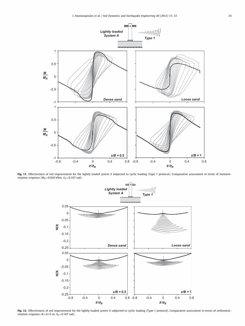
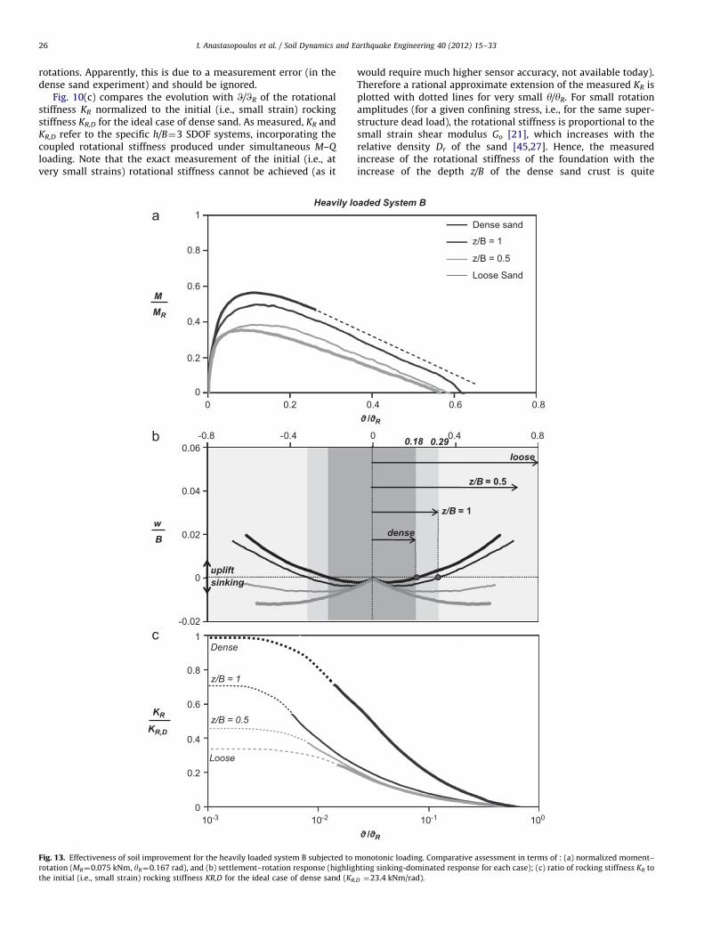
Fig. 13. Effectiveness of soil improvement for the heavily loaded system B subjected to
rotation (MR¼0.075 kNm, yR¼0.167 rad), and (b) settlement–rotation response (highlig
the initial (i.e., small strain) rocking stiffness KR,D for the ideal case of dense sand (KR
would require much higher sensor accuracy, not available today).Therefore a rational approximate extension of the measured KR isplotted with dotted lines for very small y/yR. For small rotationamplitudes (for a given confining stress, i.e., for the same super-structure dead load), the rotational stiffness is proportional to thesmall strain shear modulus Go [21], which increases with therelative density Dr of the sand [45,27]. Hence, the measuredincrease of the rotational stiffness of the foundation with theincrease of the depth z/B of the dense sand crust is quite
0 0.4 0.8
z/B = 1
loose0.18
z/B = 0.5
0.29
0.4 0.6 0.8
aded System B
10-1 100
Dense sand
Loose Sand
z/B = 1
z/B = 0.5
dense
/ R
/ R
monotonic loading. Comparative assessment in terms of : (a) normalized moment–
hting sinking-dominated response for each case); (c) ratio of rocking stiffness KR to
,D ¼23.4 kNm/rad).

I. Anastasopoulos et al. / Soil Dynamics and Earthquake Engineering 40 (2012) 15–33 27
reasonable. While in the case of the shallower z/B¼0.5 crust thestiffness almost coincides with the lower bound loose sand case,for z/B¼1 a substantial increase of KR/KR,D is observed.
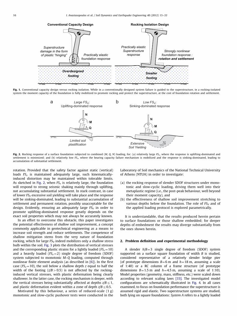
4.2. Cyclic loading
Typical cyclic pushover test results are presented in Figs. 11and 12, focusing on Type 1 loading protocol. In terms of moment-rotation response (Fig. 11), it is quite evident that as the depth z/B ofsoil improvement increases, the loops tend to transform fromoval-shaped (resembling loose sand) to the S-shaped loops of theideal case of dense sand. Interestingly, contrary to monotonic, incyclic loading all systems tend to display very similar momentcapacity. In effect, this reveals that the overstrength increases withdecreasing FSv, an observation which is consistent with the findings ofthe previous sections regarding the tests on homogenous soil.
Fig. 12 summarizes the effectiveness of the shallow soil crustin terms of settlement–rotation response, for the same loadingprotocol. The differences are now quite striking. Even with the‘‘shallow’’ z/B¼0.5 soil improvement, the response is palpablysuperior to that on loose sand. Although the accumulated settle-ment is still larger than what is observed in the ideal case of densesand, the effectiveness of the shallow dense sand crust isundeniable. A deeper z/B¼1 soil improvement is even moreeffective, leading to practically the same settlement accumulationwith the upper bound case of dense sand.
M MR
M MR
Dense sand
0 0.8-0.8 -0.4 0.4
1
-1
-0.5
0.5
0
z/B = 0.5
1
-1
-0.5
0.5
0
Heavily loadedSystem B
/ R
Fig. 14. Effectiveness of soil improvement for the heavily loaded system B subjected t
rotation response (MR¼0.075 kNm, yR¼0.167 rad).
Hence, it can be argued that a z/B¼1 dense sand crust is enough toachieve practically the same performance with the ideal case of densesand. A shallower improvement may also be considered as effective,depending on the desired performance and design requirements.
5. Effectiveness of shallow soil improvement for theheavily-loaded structure
As for the previous case, results are presented for z/B¼0.5 and1 for the heavily-loaded System B. Foundation performance indense sand is considered as the ideal case.
5.1. Monotonic loading
Fig. 13 outlines the effectiveness of shallow soil improvementfor the heavily-loaded System B subjected to monotonic pushovertesting, applying the same loading protocol (Type 1). As for thepreviously discussed lightly-loaded System A, shallow soilimprovement leads to an increase of the foundation momentcapacity (Fig. 13(a)). Interestingly, while for the light System A theshallow z/B¼0.5 soil improvement was quite effective, leading toalmost 80% enhancement of the moment capacity compared toloose sand (Fig. 10(a)), for the heavily-loaded foundation its effectis barely noticeable both in terms of moment capacity and topplingrotation. On the other hand, the deeper z/B¼1 soil improvement isstill effective, tending to approach the ideal dense sand response.A major difference between the two systems lies in the level of
Loose sand
0 0.8-0.8 -0.4 0.4
z/B = 1
Type 1
/ R
o cyclic loading (Type 1 protocol). Comparative assessment in terms of moment-

I. Anastasopoulos et al. / Soil Dynamics and Earthquake Engineering 40 (2012) 15–3328
achieved FSv: while for the lightly-loaded System A, a rather largeFSv¼14 was attained for ideal soil conditions (i.e., in dense sand),the corresponding ‘‘ideal’’ FSv does not exceed 5 for the heavily-loaded System B. As a result, even under ideal soil conditions theresponse of the heavily-loaded foundation cannot be uplifting-dominated, but is rather accompanied by mobilization of bearingcapacity and substantial soil plastification. With limited upliftingtaking place, the effective width of the foundation is not reduced asmuch, and the rocking-induced stress bulb tends to ‘‘penetrate’’deeper, in a manner qualitatively similar to the numerical exampleof Fig. 3(b).
In terms of settlement–rotation response (Fig. 13(b)) the mainconclusions drawn for the lightly-loaded System A still hold true,with the main difference being the critical improvement depth(i.e., the z/B necessary to promote uplifting). For relatively smallrotation amplitudes, y/yRo0.1, the foundation settles under anysoil conditions (even for the ideal case of dense sand). As a result,the behavior of the models on improved sand is almost identicalto that on loose sand, revealing an almost negligible effect of soilimprovement. While in loose sand (FSv¼2.6) foundation responseis sinking-dominated throughout the entire rotation range, a shifttowards uplifting is observed at W/WR¼0.18 in dense sand. In caseof the deep z/B¼1 dense sand crust, the uplifting region initiatesfor slightly larger W/WR¼0.29. The shallow z/B¼0.5 soil improve-ment cannot be considered effective, exhibiting sinking-domi-nated response throughout the entire range of W/WR.
w B
0
-0.1
-0.2
0.05
-0.05
-0.15
-0.25 Dense sand
0 0.-0.8 -0.4 0.4
w B
0
-0.1
-0.2
0.05
-0.05
-0.15
-0.25z/B = 0.5
Heavily loadedSystem B
/ R
Fig. 15. Effectiveness of soil improvement for the heavily loaded system B subjected to
rotation response (B¼0.15 m, yR¼0.167 rad).
The above mechanisms are also reflected in the measuredrocking stiffness (Fig. 13(c). Although shallow soil improvementhas a qualitatively similar effect to the previously discussed lightly-loaded System A (the rocking stiffness increases with z/B), itseffectiveness is remarkably reduced. In fact, it cannot be arguedthat the shallow z/B¼0.5 dense sand crust has any measurableeffect on the rocking stiffness. Even for the deeper z/B¼1 soilimprovement, the differences from loose sand are not that evident.
5.2. Cyclic loading
The same conclusions are drawn examining the results ofslow-cyclic pushover tests. The effectiveness of shallow soilimprovement is portrayed in Fig. 14 in terms of moment-rotationresponse (for the same loading protocol: Type 1). As for thelightly-loaded System A, thanks to the observed cyclic over-strength (which, apparently, increases with the reduction of FSv),the cyclic moment capacity is almost the same for all soil profilesexamined, especially after application of the larger amplitudes ofloading when the overstrength has been fully mobilized. Incontrast to the lightly-loaded System A, with FSv ranging from2.6 (in loose sand) to 5 (in dense sand), the moment-rotationloops are always oval-shaped.
The effectiveness of shallow soil improvement in terms ofsettlement–rotation response is summarized in Fig. 15. In accordwith the trends observed during monotonic pushover testing, the
Loose sand
8 0 0.8-0.8 -0.4 0.4
z/B = 1
Type 1
/ R
cyclic loading (Type 1 protocol). Comparative assessment in terms of settlement–
I. Anastasopoulos et al. / Soil Dynamics and Earthquake Engineering 40 (2012) 15–33 29
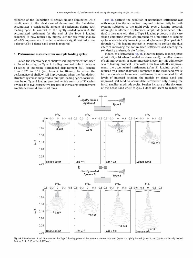
response of the foundation is always sinking-dominated. As aresult, even in the ideal case of dense sand the foundationaccumulates a considerable amount of settlement during eachloading cycle. In contrast to the lightly-loaded System A, theaccumulated settlement (at the end of the Type 1 loadingsequence) is now reduced by merely 30% for relatively shallowz/B¼0.5 improvement. In order to achieve a significant reduction,a deeper z/B¼1 dense sand crust is required.
6. Performance assessment for multiple loading cycles
So far, the effectiveness of shallow soil improvement has beenexplored focusing on Type 1 loading protocol, which contains14 cycles of increasing normalized displacement d/dR, rangingfrom 0.025 to 0.55 (i.e., from 2 to 40 mm). To assess theperformance of shallow soil improvement when the foundation-structure system is subjected to multiple loading cycles, focus willnow be on Type 2 loading protocol, which consists of 31 cycles,divided into five consecutive packets of increasing displacementamplitude (from 4 mm to 40 mm).
w B
w B
0-0.3 0.3-0.6 0.6 0-0.3 0.3-0.6 0.
Dense sand z/B = 1
Lightly loadedSystem A
0.039 0.0410.05
0.10
0.15
0.30
0
0.20
0.25
Dense sand z/B = 1
0.1680.157
0.05
0.10
0.15
0.30
0
0.20
0.25
Heavily loadedSystem B
0-0.3 0.3-0.6 0.6 0-0.3 0.3-0.6 0.
/ R / R
/ R / R
Fig. 16. Effectiveness of soil improvement for Type 2 loading protocol. Settlement–rot
System B (B¼0.15 m, yR¼0.167 rad).
Fig. 16 portrays the evolution of normalized settlement w/B
with respect to the normalized imposed rotation W/WR for bothsystems subjected to the multi-cycle Type 2 loading protocol.Although the ultimate displacement amplitude (and hence, rota-tion) is the same with that of Type 1 loading protocol, in this casestrong amplitude cycles are preceded by a multitude of loadingcycles of considerably lower imposed displacement (load packets 1through 4). This loading protocol is expected to contain the dualeffect of increasing the accumulated settlement and affecting thesoil density underneath the footing.
Indeed, as illustrated in Fig. 16(a), for the lightly-loaded System
A (with FSv¼14 when founded on dense sand), the effectivenessof soil improvement is quite impressive, even for this admittedlysevere loading protocol. Even with a shallow z/B¼0.5 improve-ment, the accumulated settlement (after 31 loading cycles) isreduced by a factor of almost 3 compared to the loose sand. Whilefor the models on loose sand, settlement is accumulated for alllevels of imposed rotation, the models on dense sand andimproved soil tend to accumulate settlement only during theinitial smaller-amplitude cycles. Further increase of the thicknessof the dense sand crust to z/B¼1 does not seem to reduce the
6 0-0.3 0.3-0.6 0.6 0-0.3 0.3-0.6 0.6
z/B = 0.5 Loose sand
Type 2
0.055
0.152
0.281z/B = 0.5 Loose sand
0.249
Type 2
6 0-0.3 0.3-0.6 0.6 0-0.3 0.3-0.6 0.6
/ R / R
/ R / R
ation response: (a) for the lightly loaded System A, and (b) for the heavily loaded

I. Anastasopoulos et al. / Soil Dynamics and Earthquake Engineering 40 (2012) 15–3330
accumulated settlement as remarkably. The observed behavior isin accord with the previously discussed monotonic settlement–rotation response.
Not surprisingly, soil improvement is not as attractive whenthe same loading protocol is applied to the heavily the applicationof shallow-loaded System B (having FSv¼5 when founded ondense sand). As shown in Fig. 16(b), on loose sand the foundationaccumulates almost two times larger settlement than System A.The shallow z/B¼0.5 soil improvement is clearly insufficient asthe entire loading history falls within the sinking-dominatedrotation range. Interestingly, in the case of the deeper z/B¼1dense sand crust, although the first four loading packets fallwithin the sinking-dominated rotation range (which ends atW/WR¼0.29), a reduction in the accumulated settlement is observedand the response tends to approach that of dense sand. However, ifwe focus on the fifth (large-amplitude) loading packet, the perfor-mance of the z/B¼1 improved soil is quite similar to the ideal caseof the homogeneous dense sand soil profile. It is worth observingthat the performance of this system founded on dense sand is quite
w B
w B
0.05
0.10
0.15
0.30
0
0.20
0.25
0 5 10
0.05
0.10
0.15
0.30
0
0.20
0.25
number of
Lightly loadedSystem A
Type 2
Heavily loadedSystem B
Type 2
Dense sand z/B = 1
1st packet 2nd
10 cycles @0.05 10 cyc
Fig. 17. Normalized settlement with respect to the number of cycles (Type 2 loading pr
(B¼0.15 m, yR¼0.167 rad).
similar to that of the lightly-loaded System A on loose sand, which ischaracterized by the same FSv¼5.
A more direct visualization of the performance of the twosystems and the effectiveness of shallow soil improvement isoffered by Fig. 17, which plots the evolution of settlement withthe number of cycles for the same loading protocol. In the case ofthe lightly-loaded System A (Fig. 17(a)), the rate of settlementaccumulation of the structure founded on improved soil matchesthe ideal case of dense sand almost right from the beginning(at n¼5), not being noticeably affected by z/B. The performance ofthe z/B¼1 soil improvement is almost identical to that of densesand, with very slight differences being observed only at the veryearly stages of loading (for no2). The shallower z/B¼0.5improvement is characterized by slightly larger settlement accu-mulation rate, but still its effectiveness is quite impressive.Almost the opposite is observed for the heavily-loaded System B
(Fig. 17(b)), where the rate of settlement accumulation is sub-stantially affected by the thickness z/B of the dense sand crust.The ideal behavior of dense sand is only approached by the deeper
15 20 25 30
cycles (n)
Loose Sandz/B = 0.5
packet 3rd packet
5 cycles @0.20
4th packet
3 @0.30 3 @0.55
5th packet
les @0.10
otocol): (a) for the lightly loaded System A, and (b) for the heavily loaded System B

I. Anastasopoulos et al. / Soil Dynamics and Earthquake Engineering 40 (2012) 15–33 31
z/B¼1 soil improvement, but is never actually matched; differ-ences are evident throughout the entire range of loading cycles,for all five loading packets.
7. Conclusions
This paper has investigated the rocking response of SDOFstructures, and the effectiveness of shallow soil improvementstretching to various depths below the foundation. For thispurpose, a series of reduced-scale monotonic and slow-cyclicpushover tests were conducted at the Laboratory of SoilMechanics of the National Technical University of Athens.Two relatively slender h/B¼3 SDOF systems were studied, bothlying on a square foundation of width B, the first (System A)corresponds to a lightly-loaded structure (relatively large FSv); thesecond (System B) refers to a heavily-loaded structure (relativelylow FSv). The two systems were used to model distinctly differentfoundation performance, from uplifting-dominated (System A) tosinking-dominated response (System B). The two systems were firsttested on ideal and poor soil conditions (dense and medium or
0.03
0.01
0.02
0 0.15 0.3
wc
B
θc /θR
0.04 0.24
0.03
0
0.01
0.02
wc
B
0.18 0.29
z/B = 0.5Loose sand z
Fig. 18. Normalized settlement per cycle with respect to normalized cyclic rotation amp
heavily loaded System B (B¼0.15 m, yR¼0.167 rad). The grey-shade areas represent the
Figs. 9 and 12).
loose sand, respectively), to demonstrate the necessity for soilimprovement. Then, the effectiveness of shallow soil improvementwas studied by investigating the performance of dense sand crustsof varying depth z/B¼0.25 to 1.
It is reminded that the conclusions of the presented researchmay only be applicable to relatively slender systems (bearing an h/B
ratio greater than or equal to 3) where rocking response dominatesover sliding. Moreover, when dealing with a frame structure theaxial loads are subject to fluctuation during strong seismic shaking,and therefore FSv will not be constant [23]. Still though, suchfluctuations are not expected to alter the main findings of thepresented research, which are summarized as follows:
1)
/B
litu
rot
When the factor of safety against vertical loads is relativelylarge (FSv410 for sand), the rocking response of the foundationis mainly uplifting-dominated, not accumulating substantialsettlement during sequential cycles of loading. For lowerFSV values (even of the order of 5 for sand) soil yielding takesplace underneath the foundation and its response becomessinking-dominated, leading to substantial accumulation ofsettlement.
0.54
0.45 0.6
= 1 Dense sand
Heavily loaded System B
Type 1
Lightly loaded System A
Type 1
de (Type 1 loading protocol): (a) for the lightly loaded System A, and (b) for the
ation range for each case, in which the response is sinking-dominated (see also

number of cycles (n)
0
0.008
0.002
0.01
0.006
0.004
0.01
0
0.008
0.006
0.004
0.002
2 4 6 8 101 3 5 7 9
Lightly loadedSystem A
Type 3
Type 3
Heavily loadedSystem B
Dense sand Loose Sandz/B = 1 z/B = 0.5
wc
B
wc
B
Fig. 19. Normalized settlement per cycle (Type 2 loading, 1st packet, W¼0.0167 rad): (a) for the lightly loaded System A, and (b) for the heavily loaded System B (B¼0.15 m,
yR¼0.167 rad).
I. Anastasopoulos et al. / Soil Dynamics and Earthquake Engineering 40 (2012) 15–3332
2)
In the context of rocking isolation, foundation rocking may bedesirable (to limit the inertia forces acting on the superstructure)but incorporates the peril of unacceptable settlements in case oflow FSv. Hence, in order to ensure that rocking is materializedthrough uplifting rather than sinking, an adequately large FSv isrequired. Although this is feasible in theory, soil properties arenot always well-known in reality, tending to limit the applic-ability of the whole concept of rocking isolation. However, sincerocking-induced soil yielding is only mobilized within a shallowlayer underneath the footing, ‘‘shallow soil improvement’’ isconsidered as an alternative approach to release the design fromthe jeopardy of an unforeseen inadequate FSv (due to over-estimation of soil properties).3)
Based on the conducted reduced-scale tests, and at least for thecases examined herein, the concept of shallow soil improve-ment is proven to be quite effective. A synopsis of test results isillustrated in Fig. 18, which plots the normalized settlement perloading cycle as a function of the imposed cyclic rotationamplitude for the two investigated systems. In the case of alightly-loaded system (having FSv¼14 in ideal soil conditions),a z/B¼1 dense sand crust is enough to achieve practicallythe same performance with the ideal case of dense sand.A shallower z/B¼0.5 soil improvement may also be consideredeffective, depending on design requirements. Although resultsare highly dependent on nonlinearities inherent in the forma-tion of the stress bulb, it may be conservatively concluded thatan improvement layer of depth equal to the foundation widthoffers a safe solution for practical applications.4)
The effectiveness of shallow soil improvement is amelioratedwith the increase of the cyclic rotation amplitude. As highlightedby the grey-shaded areas of Fig. 18 (which represent, for eachcase examined, the rotation range where the response is sinking-dominated), with the increase of soil improvement depth z/B,uplifting is promoted for a wider rotation range. For a lightly-loaded system (Fig. 18(a)), moving outside the shaded areas tolarger rotations, where the response is governed by uplifting, theperformance of shallow soil improvement becomes practicallyidentical to the ideal case of dense sand. While for small y/yR thefoundation is in full contact with the supporting soil, generatinga deeper stress bulb and hence being affected by the underlyingloose sand layer, when uplifting is initiated the effective founda-tion width is drastically decreased, reducing the depth of thegenerated stress bulb. The same conclusion is practically drawnfor a heavily-loaded structure (Fig. 18(b)).
5)
As summarized in Fig. 19, which focuses on the evolution ofnormalized settlement per cycle of loading with loading cycles(as measured during the first loading packet of Type 2 protocol),the rate of settlement reduces with the increase of loadingcycles. This decrease is even more pronounced in loose sand,which tends to densify with repeated cycles of loading.Acknowledgement
The financial support for this paper has been provided under theresearch project ‘‘DARE’’, which is funded through the EuropeanResearch Council’s (ERC) ‘‘IDEAS’’ Programme, in Support of FrontierResearch–Advanced Grant, under contract/number ERC-2-9-AdG228254–DARE to Professor G. Gazetas.
I. Anastasopoulos et al. / Soil Dynamics and Earthquake Engineering 40 (2012) 15–33 33
References
[1] Allotey N, El Naggar MH. Analytical moment-rotation curves for rigidfoundations based on a Winkler model. Soil Dynamics and EarthquakeEngineering 2003;23:367–81.
[2] Allotey N, El Naggar MH. An investigation into the winkler modeling of thecyclic response of rigid footings. Soil Dynamics and Earthquake Engineering2007;28:44–57.
[3] Anastasopoulos I. Beyond conventional capacity design: towards a new designphilosophy. In: Orense RP, Chouw N, Pender MJ, editors. Soil–Foundation–Structure Interaction. New York: CRC Press, Taylor & Francis Group; 2010.
[4] Anastasopoulos I, Gazetas G, Loli M, Apostolou M, Gerolymos N. Soil failurecan be used for seismic protection of structures. Bulletin of EarthquakeEngineering 2010;8:309–26.
[5] Anastastasopoulos I, Georgarakos P, Georgiannou V, Drosos V, Kourkoulis R.Seismic performance of Bar-Mat reinforced-soil retaining wall: shaking tabletesting versus numerical analysis with modified kinematic hardening constitu-tive model. Soil Dynamics and Earthquake Engineering 2010;30:1089–105.
[6] Anastasopoulos I, Gelagoti F, Kourkoulis R, Gazetas G. Simplified constitutivemodel for simulation of cyclic response of shallow foundations: validationagainst laboratory tests, Journal of Geotechnical and GeoenvironmetalEngineering, ASCE, in print.
[7] Bolton MD. The strength and dilatancy of sands. Geotechnique 1986;36(1):65–78.
[8] Butterfield R, Gottardi G. A complete three-dimensional failure envelope forshallow footings on sand. Geotechnique 1994;44:181–4.
[9] Butterfield R, Gottardi G. 1995. Simplifying Transformations for the Analysisof Shallow Foundations on Sand, Proc. 5th Int. Offshore and Polar Eng Conf.,The Hague, pp. 534–538.
[10] Chatzigogos CT, Pecker A, Salenc-on J. Macroelement modeling of shallowfoundations. Soil Dynamics and Earthquake Engineering 2009;29(5):765–81.
[11] Chatzigogos CT, Figini R, Pecker A, Salenc-on J. A macroelement formulationfor shallow foundations on cohesive and frictional soils. International Journalfor Numerical and Analytical Methods in Geomechanics 2010;35:902–31.
[12] Chen XL, Lai YM. Seismic response of bridge piers on elastic-plastic Winklerfoundation allowed to uplift. Journal of Sound and Vibrations 2003;266(5):957–65.
[13] Cremer C, Pecker A, Davenne L. Cyclic macro-element for soil–structureinteraction: material and geometrical nonlinearities. International Journal forNumerical and Analytical methods in Geomechanics 2001;25(12):1257–84.
[14] Drosos V, Georgarakos T, Loli M, Anastasopoulos I, Zarzouras O, Gazetas G., M.ASCE, Soil–Foundation–Structure interaction with mobilization of bearingcapacity: an experimental study on Sand. Journal of Geotechnical andGeoenvironmental Engineering, ASCE, in print.
[15] Faccioli E, Paolucci R, Vivero G. 2001. Investigation of seismic soil–footinginteraction by large scale cyclic tests and analytical models, Proc. 4thInternational Conference on Recent Advances in Geotechnical EarthquakeEngineering and Soil Dynamics, Paper no. SPL-5, San Diego, California.
[16] Figini R, Paolucci R, Chatzigogos. CT. A macro-element model for non-linearsoil-shallow foundation-structure interaction under seismic loads: theoreti-cal development and experimental validation on large scale tests. EarthquakeEngineering and Structural Dynamics 2011, http://dx.doi.org/10.1002/eqe.1140.2011 published online.
[17] Fukui J, Shirato M, Yoshinori N, Ryuichi A. 2005. Experimental study on theresidual displacement of shallow foundations subjected to cyclic loads,Technical Memorandum of PWRI, 4027, Public Works Research Institute,Tsukuba, Japan.
[18] Gajan S, Kutter BL, Phalen JD, Hutchinson TC, Martin GR. Centrifuge modelingof load-deformation behavior of rocking shallow foundations. Soil Dynamicsand Earthquake Engineering 2005;25:773–83.
[19] Gajan S, Kutter BL. Capacity, settlement, and energy dissipation of shallowfootings subjected to rocking. Journal of Geotechnical and GeoenvironmentalEngineering, ASCE 2008;134(8):1129–41.
[20] Gajan S, Kutter BL. Effects of moment-to-shear ratio on combined cyclic load-displacement behavior of shallow foundations from centrifuge experiments.Journal of Geotechnical and Geoenvironmental Engineering, ASCE 2009;135(8):1044–55.
[21] Gazetas G. Analysis of machine foundation vibrations: state of the art. SoilDynamics and Earthquake Engineering 1983;2(1):2–43.
[22] Gazetas G, Apostolou M, Anastasopoulos I. 2003. Seismic Uplifting ofFoundations on Soft Soil, with Examples from Adapazari (Izmit 1999, Earth-quake), BGA Int. Conf. on Found. Innov., Observations, Design & Practice,Univ. of Dundee, Scotland, Sept. 25, pp. 37–50.
[23] Gelagoti F, Kourkoulis R, Anastasopoulos I, Gazetas G Rocking isolation offrame structures founded on separate footings, Earthquake Engineering andStructural Dynamics, in print-a).
[24] Gelagoti F, Kourkoulis R, Anastasopoulos I, Gazetas G Rocking isolation offrames on isolated footings: design insights and limitations. Journal ofEarthquake Engineering, in print-b.
[25] Gourvenec S. Shape effects on the capacity of rectangular footings undergeneral loading. Geotechnique 2007;57(8):637–46.
[26] Grange S, Kotronis P, Mazars J. A macro-element for the circular foundationto simulate 3D soil-structure interaction. International Journal for Numericaland Analytical Methods in Geomechanics 2008;32:1205–27.
[27] Hardin BO, Richart FE. Elastic wave velocities in granular soils. Journal of theSoil Mechanics and Foundations Division, ASCE 1963;89(SM1):33–65.
[28] Houlsby GT, Amorosi A, Rojas E. Elastic moduli of soils dependent onpressure: a hyperelastic formulation. Geotechnique 2005;55(5):383–92.
[29] Kawashima K, Nagai T, Sakellaraki D. 2007 Rocking seismic isolation ofbridges supported by spread foundations. Proc. of 2nd Japan–Greece Work-shop on Seismic Design, Observation, and Retrofit of Foundations, Tokyo,Japan, pp. 254–265.
[30] Kutter BL, Martin G, Hutchinson TC, Harden C, Gajan S, Phalen JD. Statusreport on study of modeling of nonlinear cyclic load–deformation behavior ofshallow foundations.PEER Workshop. Davis: University of California; 2003.
[31] Le Pape Y, Sieffert JP. Application of thermodynamics to the global modellingof shallow foundations on frictional material. International Journal forNumerical and Analytical Methods in Geomechanics 2001;25:1377–408.
[32] Mergos PE, Kawashima K. Rocking isolation of a typical bridge pier on spreadfoundation. Journal of Earthquake Engineering 2005;9(2):395–414.
[33] Muir Wood D. 2004. Geotechnical modelling. E & FN Spon (488pp) ISBN0-419-23730-5.
[34] Nakaki DK, Hart GC. 1987 Uplifting response of structures subjected toearthquake motions, Report No. 2.1-3, U.S.–Japan Coordinated Program forMasonry Building Research.
[35] Negro P, Paolucci R, Pedretti S, Faccioli E. 2000. Large-scale soil–structureinteraction experiments on sand under cyclic loading, Proceedings of the12th World Conference on Earthquake Engineering, Auckland, NewZealand,2000, paper 1191.
[36] Nova R, Montrasio L. Settlement of shallow foundations on sand. Geotechni-que 1991;41(2):243–56.
[37] Panagiotidou AI, Gazetas G, Gerolymos N. Pushover and seismic response offoundations on stiff clay: analysis with P-D effects, Earthquake Spectra, inprint.
[38] Paolucci R. Simplified evaluation of earthquake-induced permanent displace-ments of shallow foundations. Journal of Earthquake Engineering 1997;1(3):563–79.
[39] Paolucci R, Shirato M, Yilmaz MT. Seismic behaviour of shallow foundations:shaking table experiments vs numerical modeling. Earthquake Engineeringand Structural Dynamics 2008;37:577–95.
[40] Pecker A. 1998. Capacity design principles for shallow foundations in seismicareas. Proc. 11th European Conference on Earthquake Engineering, A.A.Balkema Publishing.
[41] Pecker A. 2003. A seismic foundation design process, lessons learned fromtwo major projects: the Vasco de Gama and the Rion Antirion bridges, ACIInternational Conference on Seismic Bridge Design and Retrofit, University ofCalifornia at San Diego, La Jolla, USA.
[42] Pedretti S. 1998. Non-linear seismic soil-foundation interaction: analysis andmodeling methods, PhD Thesis, Politechnico di Milano.
[43] Priestley MJN, Seible F, Calvi GM. Seismic Design and Retrofit of Bridges. NewYork: John Wiley and Sons; 1996.
[44] Raychowdhury P, Hutchinson TC. Performance evaluation of a nonlinearWinkler-based shallow foundation model using centrifuge test results.Earthquake Engineering and Structural Dynamics 2009;38:679–98.
[45] Seed HB, Wong RT, Idriss IM, Tokimatsu K. Moduli and damping factors fordynamic analyses of cohesionless soils. Journal of Geotechnical Engineering,ASCE 1986;112(11):1016–32.
[46] Shirato M, Kouno T, Asai R, Nakani N, Fukui J, Paolucci R. Large-scaleexperiments on nonlinear behavior of shallow foundations subjected tostrong earthquakes. Soils and Foundations 2008;48(5):673–92.
[47] Taiebat HA, Carter JP. Numerical studies of the bearing capacity of shallowfoundations on cohesive soil subjected to combined loading. Geotechnique2000;50(4):409–18.
[48] Tan FS 1990. Centrifuge and theoretical modelling of conical footings onsand, Ph.D. Thesis, University of Cambridge.
[49] Yim SC, Chopra AK. Simplified earthquake analysis of structures withfoundation uplift. Journal of Structural Engineering (ASCE) 1985;111(4):906–930.