smart shuttles to complete oil and gas wells
TRANSCRIPT
(12) United States Patent Vail, 111
US006189621B1
US 6,189,621 B1 Feb. 20, 2001
(10) Patent N0.: (45) Date of Patent:
(54)
(75>
(73)
< * >
(21) (22> <51)
(52)
(58)
(56)
SMART SHUTTLES TO COMPLETE OIL AND GAS WELLS
Inventor: William Banning Vail, III, Bothell, WA (US)
Assignee: Smart Drilling and Completion, Inc., Bothell, WA (US)
Notice: Under 35 U.S.C. 154(b), the term of this patent shall be extended for 0 days.
Appl. No.: 09/375,479
Filed: Aug. 16, 1999
Int. Cl.7 .......................... .. E21B 19/00; E21B 19/22;
E21B 47/00 US. Cl. ................. .. 166/385; 166/250.01; 166/77.1;
166/241.5 Field of Search .......................... .. 166/250.01, 117.5,
166/117.6, 77.1, 241.5, 242.5, 385
References Cited
U.S. PATENT DOCUMENTS
3,552,508 1/1971 Brown ................................ .. 175/258
3,603,411 9/1971 Link ..... .. 175/259
4,009,561 3/1977 Young ........ .. 57/6
4,651,837 3/1987 May?eld ...... .. 175/262
4,909,741 3/1990 Schasteen et al. . 439/13 4,962,822 10/1990 Pascale ..... .. 175/258
5,156,213 * 10/1992 George et al .. 166/297 5,197,553 3/1993 Leturno . . . . . . . . . . .. 175/57
5,271,472 12/1993 Leturno .... .. 175/107
5,305,830 * 4/1994 Wittrisch ....................... .. 166/250.01
5,353,872 * 10/1994 Wittrisch ....................... .. 166/250.01
5,398,760 * 3/1995 George et al 166/385 5,472,057 12/1995 Winfree . . . . . . . . . . .. 175/57
5,551,521 * 9/1996 Vail, III . . . . . . . . . . .. 175/65
5,560,437 * 10/1996 Dickelet al. ...................... .. 166/385
6,061,000 * 5/2000 Edwards ........................ .. 166/250.01
OTHER PUBLICATIONS
Cablesa, Inc., Wireline Catalogue, 2000, 6 pages. Camesa, Inc., “Electromechanical Cable”, Dec. 1998, pp. 1—32. The Rochester Corporation, “Well Logging Cables”, Jul. 1999, 9 pages. Quigley, “Coiled Tubing and Its Applications”, SPE Short Course, Houston, TX, Oct. 3, 1999, 9 pages. “World Oil’s Coiled Tubing Handbook”, Gulf Publishing Co., 1993, p. 3, p. 5, pp. 45—50. * cited by examiner
Primary Examiner—Brian L. Johnson Assistant Examiner—Joselynn Sliteris
(57) ABSTRACT
Smart shuttles are used to complete oil and gas wells. Following drilling operations into a geological formation, a steel pipe is disposed in the wellbore. The steel pipe may be a standard casing installed into the wellbore using typical industry practices. Alternatively, the steel pipe may be a drill string attached to a rotary drill bit that is to remain in the wellbore following completion during so-called “one-pass drilling operations”. Using typical procedures in the industry, the well is “completed” by placing into the steel pipe various standard completion devices, many of which are conveyed into place using the drilling rig. Instead, with this invention, smart shuttles are used to convey into the steel pipe the various smart completion devices necessary to complete the oil and gas well. Smart shuttles may be attached to a Wireline, to a coiled tubing, or to a Wireline installed within coiled tubing. Of particular interest is a Wireline conveyed smart shuttle that possesses an electri cally operated internal pump that pumps ?uid from below the shuttle, to above the shuttle, that in turn causes the smart shuttle to “pump itself down” and into a horizontal wellbore. Similar comments apply to coiled tubing conveyed smart shuttles.
5 Claims, 18 Drawing Sheets

U.S. Patent Feb. 20, 2001 Sheet 1 of 18 US 6,189,621 B1
36
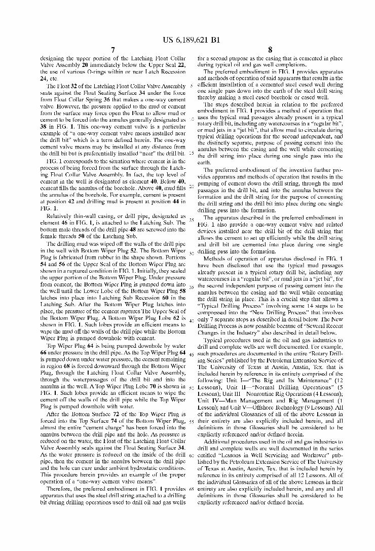
FIG. 1 PRIOR ART

U.S. Patent Feb. 20, 2001 Sheet 2 of 18 US 6,189,621 B1
100
102
FIG. 2 PRIOR ART

U.S. Patent Feb. 20, 2001 Sheet 3 of 18 US 6,189,621 B1
66
36 113
110 114 124 120
PRIOR ART 3

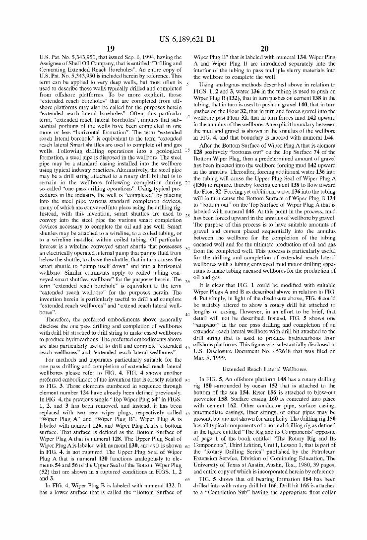
U.S. Patent Feb. 20, 2001 Sheet 4 0f 18
142
132
134 130
126
104 128 62
136
138 146 140 74
44 54 52
US 6,189,621 B1
FIG. 4
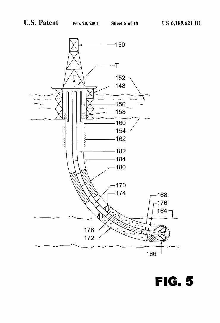
U.S. Patent Feb. 20, 2001 Sheet 5 of 18 US 6,189,621 B1
150
T
If 152
l; 1 “@651 g E /—158
160 154f 162
182 184
‘v 180 /’ //,l 170 //$/\//// 174 168 ///» Q,

U.S. Patent Feb. 20, 2001 Sheet 6 6f 18 US 6,189,621 B1
150


U.S. Patent Feb. 20, 2001 Sheet 8 of 18 US 6,189,621 B1
§<—- 338 322 B 340
326 —-————-- ‘— 334
A 336 324 ~—— 330 32o—\ W332
316
71: £319 318 / 315
_ _ /—314
L-UL/M —-§ 170 15s

U.S. Patent Feb. 20, 2001 Sheet 9 of 18 US 6,189,621 B1
0 8
w M 0 1 “M w MM
2 36 38 42 4446 0 4 4
0 9 9 2 4| 1 2
/ 3
1 3
a
w w A A_
4 6 2 6 8 0 2 0 0 O 2 0 1 4|
444 4048 3 3 3
2 m 1 0 4 3 4 4
FIG. 9
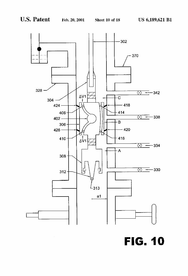


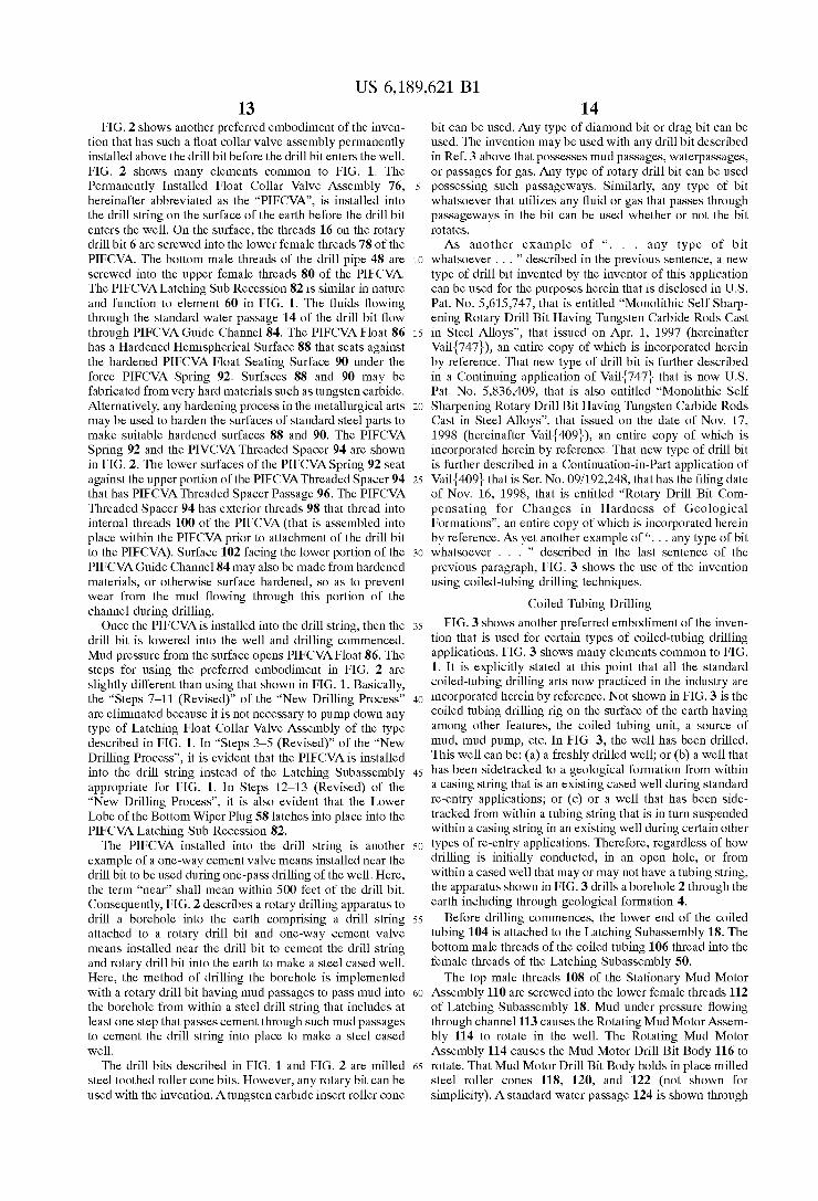
U.S. Patent Feb. 20, 2001 Sheet 12 of 18 US 6,189,621 B1
NF 6-" NE
Em


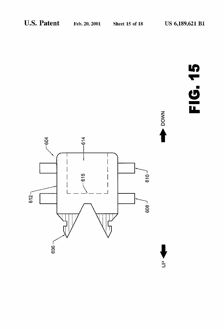
U.S. Patent Feb. 20, 2001 Sheet 15 of 18 US 6,189,621 B1
2. .2"
gall
NE
woo

U.S. Patent Feb. 20, 2001 Sheet 16 0f 18 US 6,189,621 B1
0-. .2"
oNm

U.S. Patent Feb. 20, 2001 Sheet 17 of 18 US 6,189,621 B1
656 654
6150\1 —— 652
<— 644
156 FIG. 1 7

U.S. Patent Feb. 20, 2001 Sheet 18 of 18 US 6,189,621 B1
150
668 —
FIG. 18

US 6,189,621 B1 1
SMART SHUTTLES TO COMPLETE OIL AND GAS WELLS
This application relates to Ser. No. 08/323,152, ?led Oct. 14, 1994, having the title of “Method and Apparatus for Cementing Drill Strings in Place for One Pass Drilling and Completion of Oil and Gas Wells”, that issued on Sep. 3, 1996 as US. Pat. No. 5,551,521, an entire copy of Which is incorporated herein by reference.
This application further relates to application Ser. No. 08/708,396, ?led Sep. 3, 1996, having the title of “Method and Apparatus for Cementing Drill Strings in Place for One Pass Drilling and Completion of Oil and Gas Wells”, that issued on the date of Apr. 20, 1999 as US. Pat. No. 5,894,897, an entire copy of Which is incorporated herein by reference.
This application further relates to application Ser. No. 09/294,077, ?led Apr. 18, 1999, having the title of “One Pass Drilling and Completion of Wellbores With Drill Bit Attached to Drill String to Make Cased Wellbores to Pro duce Hydrocarbons”, an entire copy of Which is incorporated herein by reference.
This application further relates to application Ser. No. 09/295,808, ?led Apr. 20, 1999, having the title of “One Pass Drilling and Completion of Extended Reach Lateral Well bores With Drill Bit Attached to Drill String to Produce Hydrocarbons from Offshore Platforms”, an entire copy of Which is incorporated herein by reference.
This application relates to disclosure in US. Disclosure Document No. 362582, ?led on Sep. 30, 1994, that is entitled ‘RE: Draft of US. patent application Entitled “Method and Apparatus for Cementing Drill Strings in Place for One Pass Drilling and Completion of Oil and Gas Wells’”, an entire copy of Which is incorporated herein by reference.
This application further relates to disclosure in US. Disclosure Document No. 445686, ?led on Oct. 11, 1998, that is entitled ‘RE:—Invention Disclosure—entitled “Wil liam Banning Vail III, Oct. 10, 1998’”, an entire copy of Which is incorporated herein by reference.
This application further relates to disclosure in US. Disclosure Document No. 451044, ?led on Feb. 8, 1999, that is entitled ‘RE:—Invention Disclosure—“Drill Bit Having Monitors and Controlled Actuators’”, an entire copy of Which is incorporated herein by reference.
This application further relates to disclosure in US. Disclosure Document No. 451292, ?led on Feb. 10, 1999, that is entitled ‘RE:—Invention Disclosure—“Method and Apparatus to Guide Direction of Rotary Drill Bit” dated Feb. 9, 1999’”, an entire copy of Which is incorporated herein by reference.
This application further relates to disclosure in US. Disclosure Document No. 452648 ?led on Mar. 5, 1999 that is entitled ‘RE: “—Invention Disclosure—Feb. 28, 1999 One-Trip-DoWn-Drilling Inventions Entirely OWned by William Banning Vail III’”, an entire copy of Which is incorporated herein by reference.
This application further relates to disclosure in US. Disclosure Document No. 455731 ?led on May 2, 1999 that is entitled ‘RE:—INVENTION DISCLOSURE—entitled “Summary of One-Trip-DoWn-Drilling Inventions”, an entire copy of Which is incorporated herein by reference.
This application further relates to disclosure in US. Disclosure Document No. 458978 ?led on Jul. 13, 1999 that is entitled in part “RE:—INVENTION DISCLOSURE MAILED JUL. 13, 1999”, an entire copy of Which is incorporated herein by reference.
10
15
20
25
30
35
40
45
50
55
60
65
2 Yet further, this application also relates to disclosure in
US. Disclosure Document No. 459470 ?led on Jul. 20, 1999 that is entitled in part ‘RE:—INVENTION DISCLOSURE ENTITLED “Different Methods and Apparatus to “Pump doWn”. . . ”’, an entire copy of Which is incorporated herein by reference.
Various references are referred to in the above de?ned U.S. Disclosure Documents. For the purposes herein, the term “reference cited in applicant’s U.S. Disclosure Docu ments” shall mean those particular references that have been explicitly listed and/or de?ned in any of applicant’s above listed U.S. Disclosure Documents and/or in the attachments ?led With those U.S. Disclosure Documents. Applicant explicitly includes herein by reference entire copies of each and every “reference cited in applicant’s U.S. Disclosure Documents”. In particular, applicant includes herein by reference entire copies of each and every US. Patent cited in US. Disclosure Document No. 452648, including all its attachments, that Was ?led on Mar. 5, 1999. To best knoWl edge of applicant, all copies of US. Patents that Were ordered from commercial sources that Were speci?ed in the US. Disclosure Documents are in the possession of appli cant at the time of the ?ling of the application herein.
BACKGROUND OF THE INVENTION
1. Field of Invention The ?eld of invention relates to apparatus that uses the
steel drill string attached to a drilling bit during drilling operations used to drill oil and gas Wells for a second purpose as the casing that is cemented in place during typical oil and gas Well completions. The ?eld of invention further relates to methods of operation of said apparatus that pro vides for the ef?cient installation of a cemented steel cased Well during one single pass doWn into the earth of the steel drill string. The ?eld of invention further relates to methods of operation of the apparatus that uses the typical mud passages already present in a typical drill bit, including any Watercourses in a “regular bit”, or mud jets in a “jet bit”, that alloW mud to circulate during typical drilling operations for the second independent, and the distinctly separate, purpose of passing cement into the annulus betWeen the casing and the Well While cementing the drill string into place during one single drilling pass into the earth. The ?eld of invention further relates to apparatus and methods of operation that provides the pumping of cement doWn the drill string, through the mud passages in the drill bit, and into the annulus betWeen the formation and the drill string for the purpose of cementing the drill string and the drill bit into place during one single drilling pass into the formation. The ?eld of invention further relates to a one-Way cement valve and related devices installed near the drill bit of the drill string that alloWs the cement to set up ef?ciently While the drill string and drill bit are cemented into place during one single drilling pass into the formation. The ?eld of invention further relates to the use of slurry material instead of cement to complete Wells, Where the term “slurry material” may be any one, or more, of at least the folloWing substances: cement, gravel, Water, “cement clinker”, a “cement and copolymer mixture”, a “blast furnace slag mixture”, and/or any mixture thereof; or any knoWn substance that ?oWs under suf?cient pressure. The ?eld of invention further relates to the use of slurry materials for the folloWing type of generic Well completions: open-hole Well completions; typical cemented Well completions having perforated cas ings; gravel Well completions having perforated casings; and for any other related Well completions. The ?eld of invention relates to using slurry materials to complete extended reach