smart arm based microcontroller...
TRANSCRIPT
APPLICATION NOTE
AT10294: Using the Sigma-Delta Analog to Digital
Converter on SAMC MCU (SDADC)
SMART ARM Based Microcontroller
Introduction
The Sigma-Delta Analog-to-Digital Converter (SDADC) converts analog signals
to digital values. The SDADC has 16-bit resolution at 1ksps and is capable of
converting up to 1.5Msps divided by the data over sampling ratio (OSR).
The input selection is up to three differential analog channels. The SDADC
provides signed results. ADC measurements can be started by either application
software or an incoming event from another peripheral in the device. ADC
measurements can be started with predictable timing and without software
intervention. The SDADC also integrates a sleep mode and a conversion
sequencer. These features reduce power consumption and processor
intervention. A set of reference voltages are generated internally.
Features
Sigma-Delta converter with up to 16-bit resolution at 1ksps
Three external analog differential input pairs
Conversion range 0V to a wide range of VREF options
Hardware gain, offset, and shift compensation
Atmel-42467A-Using-the-Signa-Delta-Analog-to-Digital-Converter-on-SAMC-MCU-(SDADC)_ApplicationNote_062015
AT10294: Using the Sigma-Delta Analog to Digital Converter on SAMC MCU (SDADC) [APPLICATION NOTE] Atmel-42467A-Using-the-Signa-Delta-Analog-to-Digital-Converter-on-SAMC-MCU-(SDADC)_ApplicationNote_062015 2
2
Table of Contents
1 Prerequisites ............................................................................................................................... 3
2 Module Overview ........................................................................................................................ 3
2.1 Description ........................................................................................................................................................... 3
2.2 Register Interface ................................................................................................................................................. 4
3 Functional Description .............................................................................................................. 4
3.1 Basic Operation .................................................................................................................................................... 5
3.1.1 Initialization .............................................................................................................................................. 5
3.1.2 Reading the Results ................................................................................................................................ 5
3.2 Usage Summary................................................................................................................................................... 6
4 Firmware Implementation .......................................................................................................... 6
4.1 Peripheral APIs .................................................................................................................................................... 6
4.2 Callback APIs ....................................................................................................................................................... 7
4.3 Support APIs ........................................................................................................................................................ 7
4.4 SDADC Example .................................................................................................................................................. 7
4.4.1 Requirements .......................................................................................................................................... 7
4.4.2 Description ............................................................................................................................................... 7
5 Software License ...................................................................................................................... 10
6 Revision History ....................................................................................................................... 11
AT10294: Using the Sigma-Delta Analog to Digital Converter on SAMC MCU (SDADC) [APPLICATION NOTE] Atmel-42467A-Using-the-Signa-Delta-Analog-to-Digital-Converter-on-SAMC-MCU-(SDADC)_ApplicationNote_062015
3
3
1 Prerequisites
The example firmware requires the following:
1. Xplained Pro SAMC21 development board.
2. Atmel® Studio version 6.2.1563 – Service Pack 2 or higher.
3. Atmel Software Framework (ASF) version 3.21.8 or higher.
2 Module Overview
2.1 Description
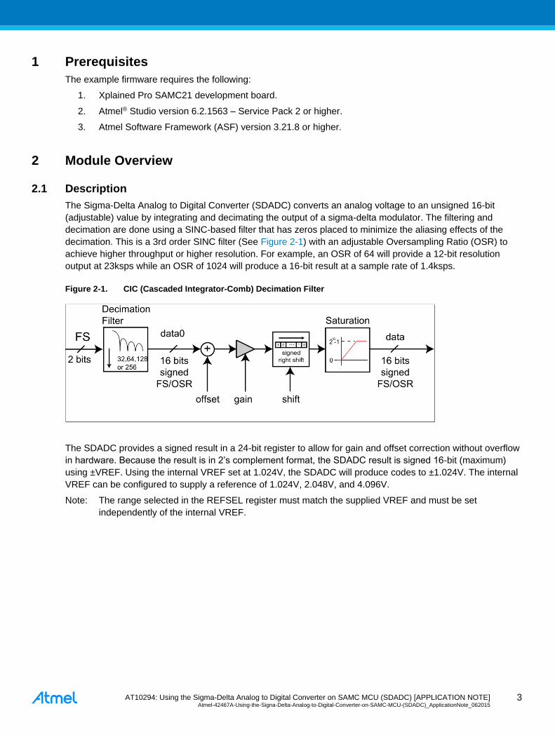
The Sigma-Delta Analog to Digital Converter (SDADC) converts an analog voltage to an unsigned 16-bit
(adjustable) value by integrating and decimating the output of a sigma-delta modulator. The filtering and
decimation are done using a SINC-based filter that has zeros placed to minimize the aliasing effects of the
decimation. This is a 3rd order SINC filter (See Figure 2-1) with an adjustable Oversampling Ratio (OSR) to
achieve higher throughput or higher resolution. For example, an OSR of 64 will provide a 12-bit resolution
output at 23ksps while an OSR of 1024 will produce a 16-bit result at a sample rate of 1.4ksps.
Figure 2-1. CIC (Cascaded Integrator-Comb) Decimation Filter
The SDADC provides a signed result in a 24-bit register to allow for gain and offset correction without overflow
in hardware. Because the result is in 2’s complement format, the SDADC result is signed 16-bit (maximum)
using ±VREF. Using the internal VREF set at 1.024V, the SDADC will produce codes to ±1.024V. The internal
VREF can be configured to supply a reference of 1.024V, 2.048V, and 4.096V.
Note: The range selected in the REFSEL register must match the supplied VREF and must be set
independently of the internal VREF.
AT10294: Using the Sigma-Delta Analog to Digital Converter on SAMC MCU (SDADC) [APPLICATION NOTE] Atmel-42467A-Using-the-Signa-Delta-Analog-to-Digital-Converter-on-SAMC-MCU-(SDADC)_ApplicationNote_062015 4
4
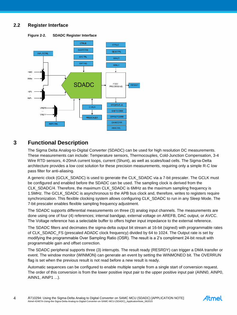
2.2 Register Interface
Figure 2-2. SDADC Register Interface
3 Functional Description
The Sigma Delta Analog-to-Digital Converter (SDADC) can be used for high resolution DC measurements.
These measurements can include: Temperature sensors, Thermocouples, Cold-Junction Compensation, 3-4
Wire RTD sensors, 4-20mA current loops, current (Shunt), as well as scales/load cells. The Sigma-Delta
architecture provides a low cost solution for these precision measurements, requiring only a simple R-C low
pass filter for anti-aliasing.
A generic clock (GCLK_SDADC) is used to generate the CLK_SDADC via a 7-bit prescaler. The GCLK must
be configured and enabled before the SDADC can be used. The sampling clock is derived from the
CLK_SDADC/4. Therefore, the maximum CLK_SDADC is 6MHz as the maximum sampling frequency is
1.5MHz. The GCLK_SDADC is asynchronous to the APB bus clock and, therefore, writes to registers require
synchronization. This flexible clocking system allows configuring CLK_SDADC to run in any Sleep Mode. The
7-bit prescaler enables flexible sampling frequency adjustment.
The SDADC supports differential measurements on three (3) analog input channels. The measurements are
done using one of four (4) references; internal bandgap, external voltage on AREFB, DAC output, or AVCC.
The Voltage reference has a selectable buffer to offers higher input impedance to the external reference.
The SDADC filters and decimates the sigma-delta output bit stream at 16-bit (signed) with programmable rates
of CLK_SDADC_FS (prescaled ADADC clock frequency) divided by 64 to 1024. The Output rate is set by
modifying the programmable Over Sampling Ratio (OSR). The result is a 2’s compliment 24-bit result with
programmable gain and offset correction.
The SDADC peripheral supports three (3) interrupts. The result ready (RESRDY) can trigger a DMA transfer or
event. The window monitor (WINMON) can generate an event by setting the WINMONEO bit. The OVERRUN
flag is set when the previous result is not read before a new result is ready.
Automatic sequences can be configured to enable multiple sample from a single start of conversion request.
The order of this conversion is from the lower positive input pair to the upper positive input pair (AINN0, AINP0,
AINN1, AINP1 ...).
AT10294: Using the Sigma-Delta Analog to Digital Converter on SAMC MCU (SDADC) [APPLICATION NOTE] Atmel-42467A-Using-the-Signa-Delta-Analog-to-Digital-Converter-on-SAMC-MCU-(SDADC)_ApplicationNote_062015
5
5
Note: If SEQCTRL register has no bits set to one, the conversion is done with the selected INPUTCTRL
input (MUXSEL). Window monitor can be used to define a threshold and trigger the WINMON flag (or
interrupt).
3.1 Basic Operation
3.1.1 Initialization
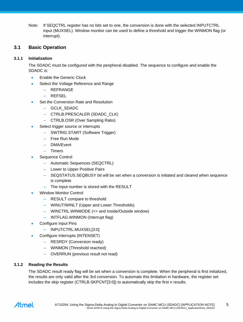
The SDADC must be configured with the peripheral disabled. The sequence to configure and enable the
SDADC is:
Enable the Generic Clock
Select the Voltage Reference and Range
– REFRANGE
– REFSEL
Set the Conversion Rate and Resolution
– GCLK_SDADC
– CTRLB.PRESCALER (SDADC_CLK)
– CTRLB.OSR (Over Sampling Ratio)
Select trigger source or interrupts
– SWTRIG.START (Software Trigger)
– Free Run Mode
– DMA/Event
– Timers
Sequence Control
– Automatic Sequences (SEQCTRL)
– Lower to Upper Positive Pairs
– SEQSTATUS.SEQBUSY bit will be set when a conversion is initiated and cleared when sequence
is complete
– The input number is stored with the RESULT
Window Monitor Control
– RESULT compare to threshold
– WINUT/WINLT (Upper and Lower Thresholds)
– WINCTRL.WINMODE (<> and Inside/Outside window)
– INTFLAG.WINMON (Interrupt flag)
Configure Input Pins
– INPUTCTRL.MUXSEL[3:0]
Configure Interrupts (INTENSET)
– RESRDY (Conversion ready)
– WINMON (Threshold reached)
– OVERRUN (previous result not read)
3.1.2 Reading the Results
The SDADC result ready flag will be set when a conversion is complete. When the peripheral is first initialized,
the results are only valid after the 3rd conversion. To automate this limitation in hardware, the register set
includes the skip register (CTRLB.SKPCNT[3:0]) to automatically skip the first n results.
AT10294: Using the Sigma-Delta Analog to Digital Converter on SAMC MCU (SDADC) [APPLICATION NOTE] Atmel-42467A-Using-the-Signa-Delta-Analog-to-Digital-Converter-on-SAMC-MCU-(SDADC)_ApplicationNote_062015 6
6
When in free running mode, the application must read the result prior to the next result being ready. If this does
not happen, the overrun flag will be set.
The result is read form RESULT and is 24-bit. To get the 12-16 bit conversion result based on the OSR, the
application will need to shift the results. However, this can be accomplished in hardware using the SHFTCORR
register to define a number of right shifts to be done automatically. Also, a fixed gain can be applied in the
same way. Care must be taken to set the gain to at least 1 if not used as it is automatically applied.
3.2 Usage Summary
Initialization:
Enable Generic Clock
Select VREF
Set Sampling Frequency (GCLK / Prescaler = CLK_SDADC)
Configure input MUX
Configure Interrupts
Trigger to start conversion(s)
Reading Results:
Skip at least the first three conversions
Start conversion(s)
Wait for RESRDY flag
Read Result and right shift in application or in hardware via SHIFTCORR
4 Firmware Implementation
SDADC drivers are a part of Atmel Studio Framework. Easy to use APIs have been provided to use the
peripheral. There are two example projects included in the ASF as part of the firmware support package for the
SAMC21 Xplained Pro Development Board. These examples demonstrate the basic use of the SDADC in
polled and interrupt, or callback, modes. Both these implementations are demonstrated in the application
example accompanying this application note.
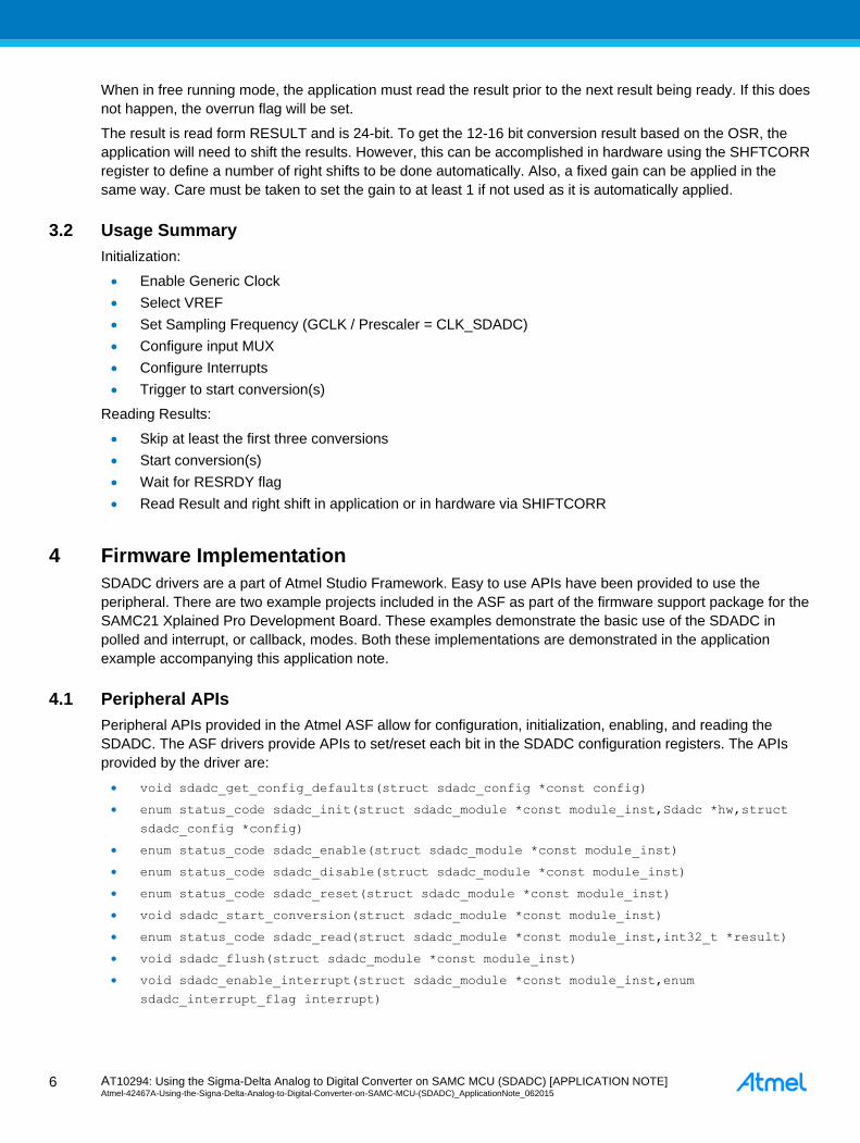
4.1 Peripheral APIs
Peripheral APIs provided in the Atmel ASF allow for configuration, initialization, enabling, and reading the
SDADC. The ASF drivers provide APIs to set/reset each bit in the SDADC configuration registers. The APIs
provided by the driver are:
void sdadc_get_config_defaults(struct sdadc_config *const config)
enum status_code sdadc_init(struct sdadc_module *const module_inst,Sdadc *hw,struct
sdadc_config *config)
enum status_code sdadc_enable(struct sdadc_module *const module_inst)
enum status_code sdadc_disable(struct sdadc_module *const module_inst)
enum status_code sdadc_reset(struct sdadc_module *const module_inst)
void sdadc_start_conversion(struct sdadc_module *const module_inst)
enum status_code sdadc_read(struct sdadc_module *const module_inst,int32_t *result)
void sdadc_flush(struct sdadc_module *const module_inst)
void sdadc_enable_interrupt(struct sdadc_module *const module_inst,enum
sdadc_interrupt_flag interrupt)
AT10294: Using the Sigma-Delta Analog to Digital Converter on SAMC MCU (SDADC) [APPLICATION NOTE] Atmel-42467A-Using-the-Signa-Delta-Analog-to-Digital-Converter-on-SAMC-MCU-(SDADC)_ApplicationNote_062015
7
7
void sdadc_disable_interrupt(struct sdadc_module *const module_inst,enum
sdadc_interrupt_flag interrupt)
uint32_t sdadc_get_status(struct sdadc_module *const module_inst)
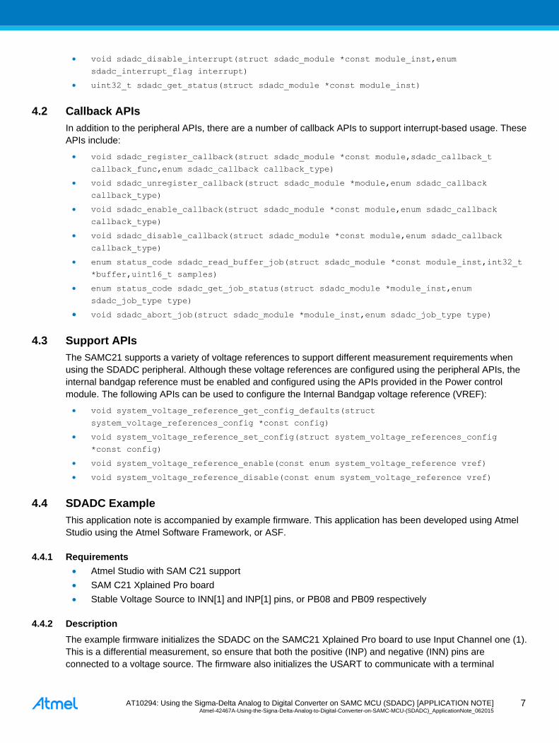
4.2 Callback APIs
In addition to the peripheral APIs, there are a number of callback APIs to support interrupt-based usage. These
APIs include:
void sdadc_register_callback(struct sdadc_module *const module,sdadc_callback_t
callback_func,enum sdadc_callback callback_type)
void sdadc_unregister_callback(struct sdadc_module *module,enum sdadc_callback
callback_type)
void sdadc_enable_callback(struct sdadc_module *const module,enum sdadc_callback
callback_type)
void sdadc_disable_callback(struct sdadc_module *const module,enum sdadc_callback
callback_type)
enum status_code sdadc_read_buffer_job(struct sdadc_module *const module_inst,int32_t
*buffer,uint16_t samples)
enum status_code sdadc_get_job_status(struct sdadc_module *module_inst,enum
sdadc_job_type type)
void sdadc_abort_job(struct sdadc_module *module_inst,enum sdadc_job_type type)
4.3 Support APIs
The SAMC21 supports a variety of voltage references to support different measurement requirements when
using the SDADC peripheral. Although these voltage references are configured using the peripheral APIs, the
internal bandgap reference must be enabled and configured using the APIs provided in the Power control
module. The following APIs can be used to configure the Internal Bandgap voltage reference (VREF):
void system_voltage_reference_get_config_defaults(struct
system_voltage_references_config *const config)
void system_voltage_reference_set_config(struct system_voltage_references_config
*const config)
void system_voltage_reference_enable(const enum system_voltage_reference vref)
void system_voltage_reference_disable(const enum system_voltage_reference vref)
4.4 SDADC Example
This application note is accompanied by example firmware. This application has been developed using Atmel
Studio using the Atmel Software Framework, or ASF.
4.4.1 Requirements
Atmel Studio with SAM C21 support
SAM C21 Xplained Pro board
Stable Voltage Source to INN[1] and INP[1] pins, or PB08 and PB09 respectively
4.4.2 Description
The example firmware initializes the SDADC on the SAMC21 Xplained Pro board to use Input Channel one (1).
This is a differential measurement, so ensure that both the positive (INP) and negative (INN) pins are
connected to a voltage source. The firmware also initializes the USART to communicate with a terminal

AT10294: Using the Sigma-Delta Analog to Digital Converter on SAMC MCU (SDADC) [APPLICATION NOTE] Atmel-42467A-Using-the-Signa-Delta-Analog-to-Digital-Converter-on-SAMC-MCU-(SDADC)_ApplicationNote_062015 8
8
program via the on-board CDC USB port (this is the same port as the EDBG port). Settings are: 115200, 8, N,
1.
Upon power-up, the SDADC is configured for polled mode, using the standard defaults. These defaults can be
found in the sdadc.h file and are stored in the config struct supplied by ASF (see Table 4-1). Notice the SDADC
is configured to use the internal VREF and the range is set to 1V full scale. Also, the default setting for the
OSR is 64, or 12-bit resolution. Pressing the ‘c’ key (while in the terminal window) will start a single, blocking,
conversion, and print the result when conversion is complete.
Table 4-1. Default Configuration Structure
config->clock_source = GCLK_GENERATOR_0;
config->reference.ref_sel = SDADC_REFERENCE_INTREF;
config->reference.ref_range = SDADC_REFRANGE_0;
config->reference.on_ref_buffer = false;
config->clock_prescaler = 2;
config->osr = SDADC_OVER_SAMPLING_RATIO64;
config->skip_count = 2;
config->mux_input = SDADC_MUX_INPUT_AIN1;
config->event_action = SDADC_EVENT_ACTION_DISABLED;
config->freerunning = false;
config->run_in_standby = false;
config->on_command = false;
config->seq_enable[0] = false;
config->seq_enable[1] = false;
config->seq_enable[2] = false;
config->window.window_mode = SDADC_WINDOW_MODE_DISABLE;
config->window.window_upper_value = 0;
config->window.window_lower_value = 0;
config->correction.gain_correction = 1;
config->correction.offset_correction = SDADC_OFFSETCORR_RESETVALUE;
config->correction.shift_correction = SDADC_SHIFTCORR_RESETVALUE;
AT10294: Using the Sigma-Delta Analog to Digital Converter on SAMC MCU (SDADC) [APPLICATION NOTE] Atmel-42467A-Using-the-Signa-Delta-Analog-to-Digital-Converter-on-SAMC-MCU-(SDADC)_ApplicationNote_062015
9
9
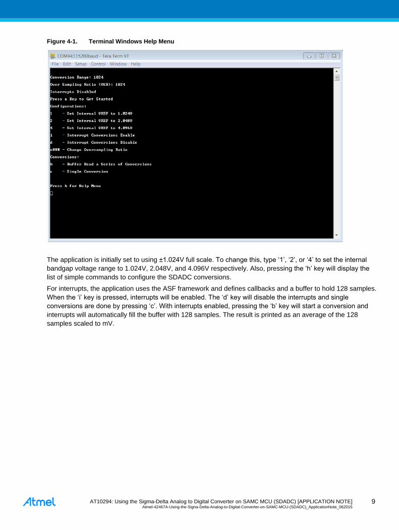
Figure 4-1. Terminal Windows Help Menu
The application is initially set to using ±1.024V full scale. To change this, type ‘1’, ‘2’, or ‘4’ to set the internal
bandgap voltage range to 1.024V, 2.048V, and 4.096V respectively. Also, pressing the ‘h’ key will display the
list of simple commands to configure the SDADC conversions.
For interrupts, the application uses the ASF framework and defines callbacks and a buffer to hold 128 samples.
When the ‘i’ key is pressed, interrupts will be enabled. The ‘d’ key will disable the interrupts and single
conversions are done by pressing ‘c’. With interrupts enabled, pressing the ‘b’ key will start a conversion and
interrupts will automatically fill the buffer with 128 samples. The result is printed as an average of the 128
samples scaled to mV.
AT10294: Using the Sigma-Delta Analog to Digital Converter on SAMC MCU (SDADC) [APPLICATION NOTE] Atmel-42467A-Using-the-Signa-Delta-Analog-to-Digital-Converter-on-SAMC-MCU-(SDADC)_ApplicationNote_062015 1
0
10
5 Software License
Redistribution and use in source and binary forms, with or without modification, are permitted provided that the
following conditions are met:
1. Redistributions of source code must retain the above copyright notice, this list of conditions and the
following disclaimer.
2. Redistributions in binary form must reproduce the above copyright notice, this list of conditions and the
following disclaimer in the documentation and/or other materials provided with the distribution.
3. The name of Atmel may not be used to endorse or promote products derived from this software without
specific prior written permission.
4. This software may only be redistributed and used in connection with an Atmel microcontroller product.
THIS SOFTWARE IS PROVIDED BY ATMEL "AS IS" AND ANY EXPRESS OR IMPLIED WARRANTIES,
INCLUDING, BUT NOT LIMITED TO, THE IMPLIED WARRANTIES OF MERCHANTABILITY, FITNESS FOR
A PARTICULAR PURPOSE AND NON-INFRINGEMENT ARE EXPRESSLY AND SPECIFICALLY
DISCLAIMED. IN NO EVENT SHALL ATMEL BE LIABLE FOR ANY DIRECT, INDIRECT, INCIDENTAL,
SPECIAL, EXEMPLARY, OR CONSEQUENTIAL DAMAGES (INCLUDING, BUT NOT LIMITED TO,
PROCUREMENT OF SUBSTITUTE GOODS OR SERVICES; LOSS OF USE, DATA, OR PROFITS; OR
BUSINESS INTERRUPTION) HOWEVER CAUSED AND ON ANY THEORY OF LIABILITY, WHETHER IN
CONTRACT, STRICT LIABILITY, OR TORT (INCLUDING NEGLIGENCE OR OTHERWISE) ARISING IN ANY
WAY OUT OF THE USE OF THIS SOFTWARE, EVEN IF ADVISED OF THE POSSIBILITY OF SUCH
DAMAGE.
AT10294: Using the Sigma-Delta Analog to Digital Converter on SAMC MCU (SDADC) [APPLICATION NOTE] Atmel-42467A-Using-the-Signa-Delta-Analog-to-Digital-Converter-on-SAMC-MCU-(SDADC)_ApplicationNote_062015
11
11
6 Revision History
Doc Rev. Date Comments
42467A 06/2015 Initial document release.
AT10294: Using the Sigma-Delta Analog to Digital Converter on SAMC MCU (SDADC) [APPLICATION NOTE] Atmel-42467A-Using-the-Signa-Delta-Analog-to-Digital-Converter-on-SAMC-MCU-(SDADC)_ApplicationNote_062015 1
2
12
Atmel Corporation 1600 Technology Drive, San Jose, CA 95110 USA T: (+1)(408) 441.0311 F: (+1)(408) 436.4200 │ www.atmel.com
© 2014 Atmel Corporation. / Rev.:Atmel-42467A-Using-the-Signa-Delta-Analog-to-Digital-Converter-on-SAMC-MCU-(SDADC)_ApplicationNote_062015. Atmel®, Atmel logo and combinations thereof, Enabling Unlimited Possibilities®, and others are registered trademarks or trademarks of Atmel Corporation in U.S. and other countries. ARM®, ARM Connected® logo, and others are the registered trademarks or trademarks of ARM Ltd. Other terms and product names may be trademarks of others. DISCLAIMER: The information in this document is provided in connection with Atmel products. No license, express or implied, b y estoppel or otherwise, to any intellectual property right is granted by this document or in connection with the sale of Atmel products. EXCEPT AS SET FORTH IN THE ATMEL TERMS AND CONDITIONS OF SALES LOCATED ON THE ATMEL WEBSITE, ATMEL ASSUMES NO LIABILITY WHATSOEVER AND DISCLAIMS ANY EXPRESS, IMPLIED OR STATUTORY WARRANTY RELAT ING TO ITS PRODUCTS INCLUDING, BUT NOT LIMITED TO, THE IMPLIED WARRANTY OF MERCHANTABILITY, FITNESS FOR A PARTICULAR PURPOSE, OR NON-INFRINGEMENT. IN NO EVENT SHALL ATMEL BE LIABLE FOR ANY DIRECT, INDIRECT, CONSEQUENTIAL, PUNITIVE, SPECIAL OR INCIDENTAL DAMAGES (INCLUDING, WITHOUT LIMITATION, DAMAGES FOR LOSS AND PROFITS, BUSINESS INTERRUPTION, OR LOSS OF INFORMATION) ARISING OUT OF THE USE OR INABILITY TO USE THIS DOCUMENT , EVEN IF ATMEL HAS BEEN ADVISED OF THE POSSIBILITY OF SUCH DAMAGES. Atmel makes no representations or warranties with respect to the accuracy or completeness of the contents of this document and reserves the right to make changes to specifications and products descriptions at any time without notice. Atmel does not make any commitment to update the information contained herein. Unless specifically provided otherwise, Atmel products are not suitable for, and shall not be used in, auto motive applications. Atmel products are not intended,
authorized, or warranted for use as components in applications intended to support or sustain life.
SAFETY-CRITICAL, MILITARY, AND AUTOMOTIVE APPLICATIONS DISCLAIMER: Atmel products are not designed for and will not be used in conne ction with any applications where the failure of such products would reasonably be expected to result in significant personal injury or death (“Safety-Critical Applications”) without an Atmel officer's specific written consent. Safety-Critical Applications include, without limitation, life support devices and systems, equipment or systems for the operation of nuclear facilities and weapons systems. Atmel products are not designed nor intended for use in military or aerospace applications or environments unless specifically desi gnated by Atmel as military-grade. Atmel products are not
designed nor intended for use in automotive applications unless specifically designated by Atmel as automotive -grade.