small engine efi control system solution - nxp...
TRANSCRIPT
External Use
TM
Small Engine EFI Control
System Solution
FTF-AUT-F0002
A P R . 2 0 1 4
Majid Eshaghi | Product Line Manager
TM
External Use 1
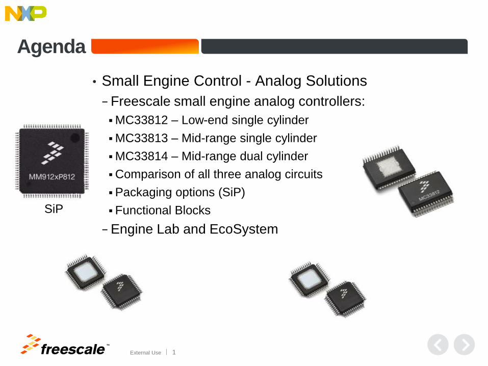
Agenda
• Small Engine Control - Analog Solutions
− Freescale small engine analog controllers:
MC33812 – Low-end single cylinder
MC33813 – Mid-range single cylinder
MC33814 – Mid-range dual cylinder
Comparison of all three analog circuits
Packaging options (SiP)
Functional Blocks
− Engine Lab and EcoSystem
SiP
TM
External Use 2
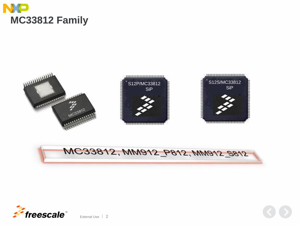
MC33812 Family
S12S/MC33812
SiP S12P/MC33812
SiP
TM
External Use 3
Engine Temp
Accelerator
Position
Inlet Air
Temp
Manifold
pressure
ADC
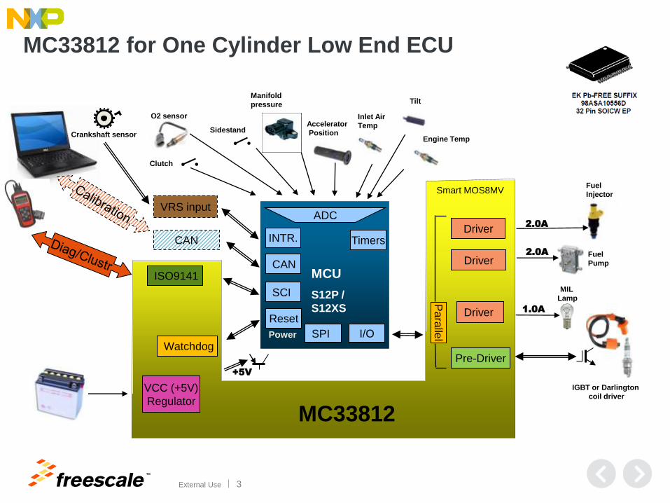
VCC (+5V)
Regulator
Reset
Power
ISO9141
SCI
CAN
I/O
Clutch
Sidestand
O2 sensor
Watchdog
Tilt
SPI
INTR. Timers
MCU
S12P /
S12XS
+5V
MC33812
Smart MOS8MV
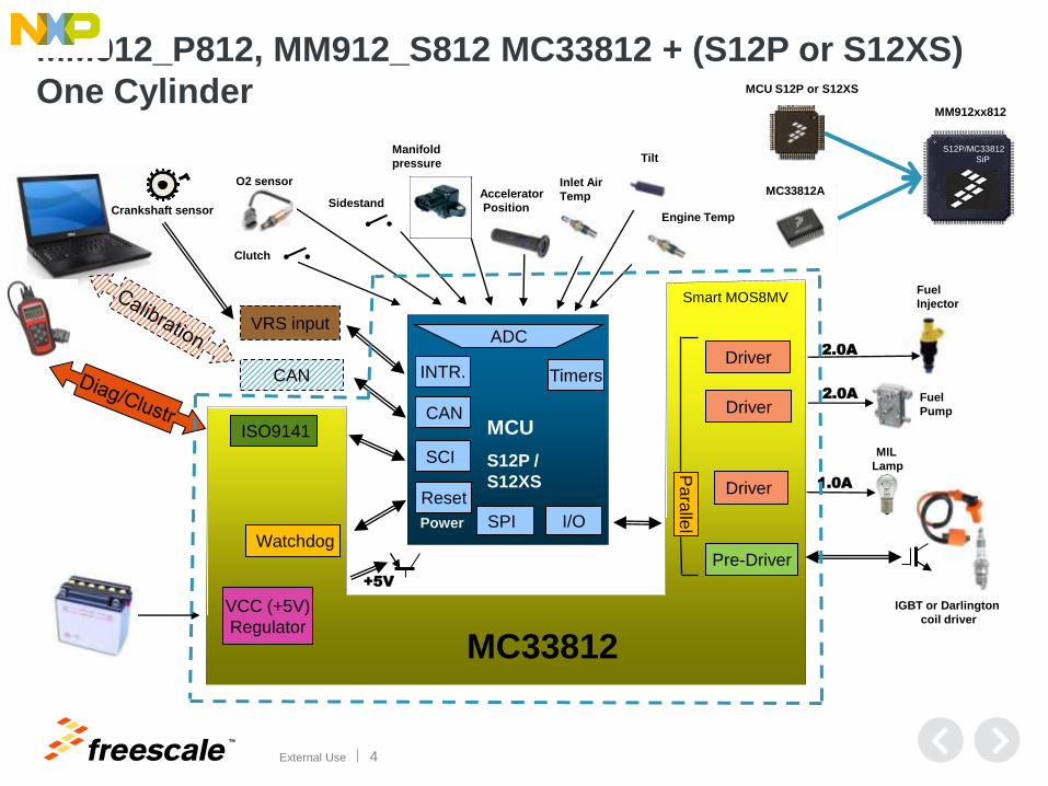
MC33812 for One Cylinder Low End ECU
CAN
Crankshaft sensor
VRS input
Fuel
Injector
Pre-Driver
Driver
IGBT or Darlington
coil driver
Driver P
ara
llel
2.0A
1.0A
MIL
Lamp
Fuel
Pump Driver 2.0A
TM
External Use 4
Engine Temp
Accelerator
Position
Inlet Air
Temp
Manifold
pressure
ADC
VCC (+5V)
Regulator
Reset
Power
ISO9141
SCI
CAN
I/O
Clutch
Sidestand
O2 sensor
Watchdog
Tilt
SPI
INTR. Timers
MCU
S12P /
S12XS
+5V
MC33812
Smart MOS8MV
MM912_P812, MM912_S812 MC33812 + (S12P or S12XS)
One Cylinder
CAN
Crankshaft sensor
VRS input
Fuel
Injector
Pre-Driver
Driver
IGBT or Darlington
coil driver
Driver P
ara
llel
2.0A
1.0A
MIL
Lamp
Fuel
Pump Driver 2.0A
S12P/MC33812
SiP
MCU S12P or S12XS
MC33812A
MM912xx812
TM
External Use 5
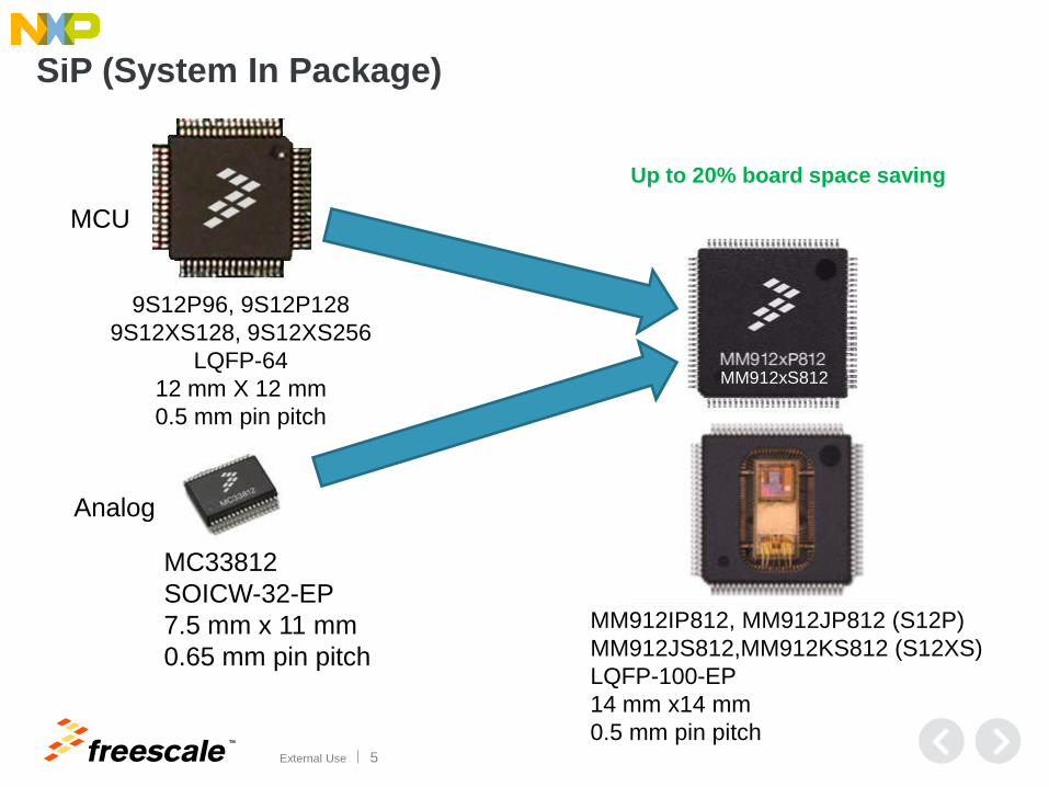
SiP (System In Package)
9S12P96, 9S12P128
9S12XS128, 9S12XS256
LQFP-64
12 mm X 12 mm
0.5 mm pin pitch
MM912IP812, MM912JP812 (S12P)
MM912JS812,MM912KS812 (S12XS)
LQFP-100-EP
14 mm x14 mm
0.5 mm pin pitch
MC33812
SOICW-32-EP
7.5 mm x 11 mm
0.65 mm pin pitch
MCU
Analog
MM912xS812
Up to 20% board space saving
TM
External Use 6
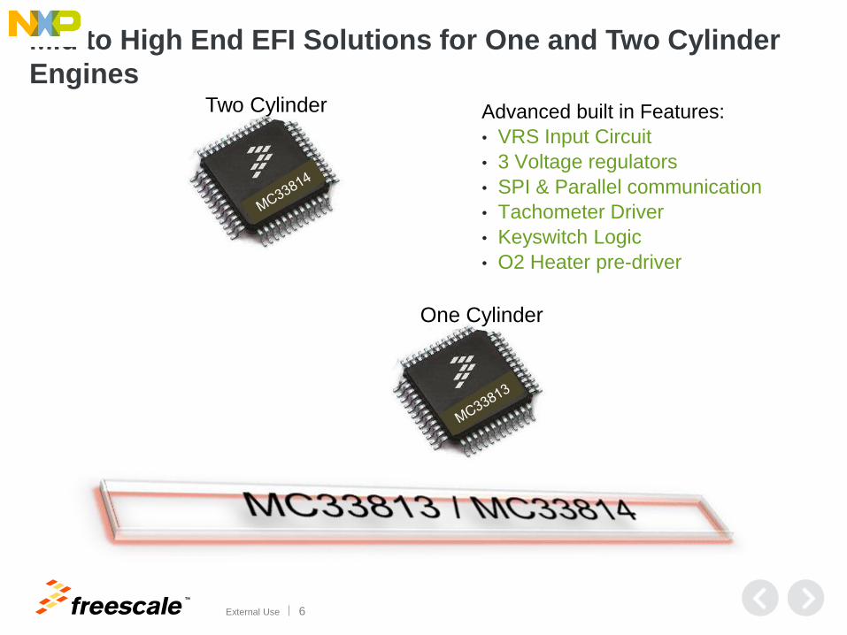
Mid to High End EFI Solutions for One and Two Cylinder
Engines
Advanced built in Features:
• VRS Input Circuit
• 3 Voltage regulators
• SPI & Parallel communication
• Tachometer Driver
• Keyswitch Logic
• O2 Heater pre-driver
Two Cylinder
One Cylinder
TM
External Use 7
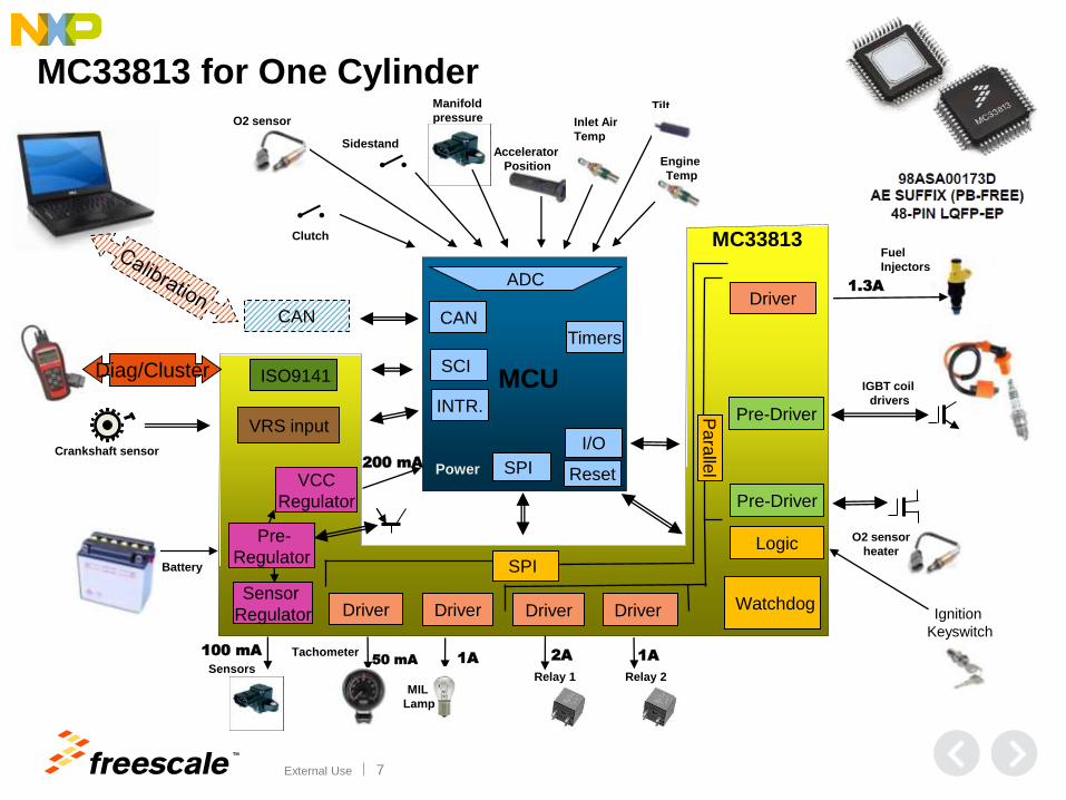
MC33813 for One Cylinder
Fuel
Injectors
Inlet Air
Temp
Manifold
pressure
ADC
Pre-
Regulator
MC33813
Pre-Driver
Driver
Reset Power
MCU
Driver
ISO9141
CAN
SCI
CAN
SPI
I/O
Clutch
Sidestand
O2 sensor
Watchdog
Driver
SPI
Pa
ralle
l
Pre-Driver
Relay 2
Driver
2A
1.3A
1A
Crankshaft sensor
VRS input INTR.
1A 50 mA
Sensor
Regulator
100 mA
Sensors
Timers
VCC
Regulator
MIL
Lamp
Tilt
Engine
Temp
Accelerator
Position
Diag/Cluster
Battery
Ignition
Keyswitch
Logic
Tachometer
Driver
200 mA
Relay 1
IGBT coil
drivers
O2 sensor
heater
TM
External Use 8
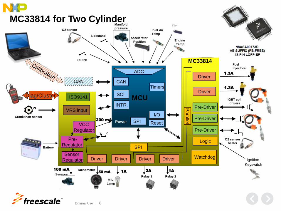
MC33814 for Two Cylinder
Fuel
Injectors
Inlet Air
Temp
Manifold
pressure
ADC
Pre-
Regulator
MC33814
Driver
Pre-Driver
Driver
Reset Power
MCU
Driver
ISO9141
CAN
SCI
CAN
SPI
I/O
Clutch
Sidestand
O2 sensor
Watchdog
Driver
Pre-Driver SPI
Pa
ralle
l
Pre-Driver
Relay 2
Driver
2A
1.3A
1.3A
1A
Crankshaft sensor
VRS input INTR.
1A 50 mA
Sensor
Regulator
100 mA
Sensors
Timers
VCC
Regulator
MIL
Lamp
Tilt
Engine
Temp
Accelerator
Position
Diag/Cluster
Battery
Ignition
Keyswitch
Logic
Tachometer
Driver
200 mA
Relay 1
IGBT coil
drivers
O2 sensor
heater
TM
External Use 9
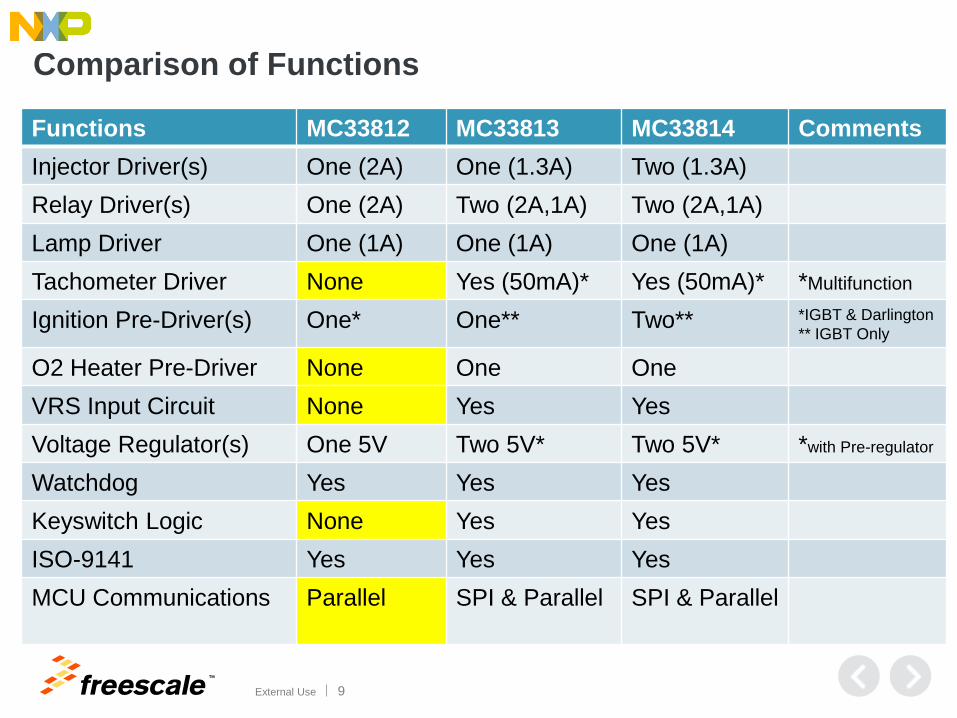
Functions MC33812 MC33813 MC33814 Comments
Injector Driver(s) One (2A) One (1.3A) Two (1.3A)
Relay Driver(s) One (2A) Two (2A,1A) Two (2A,1A)
Lamp Driver One (1A) One (1A) One (1A)
Tachometer Driver None Yes (50mA)* Yes (50mA)* *Multifunction
Ignition Pre-Driver(s) One* One** Two** *IGBT & Darlington
** IGBT Only
O2 Heater Pre-Driver None One One
VRS Input Circuit None Yes Yes
Voltage Regulator(s) One 5V Two 5V* Two 5V* *with Pre-regulator
Watchdog Yes Yes Yes
Keyswitch Logic None Yes Yes
ISO-9141 Yes Yes Yes
MCU Communications Parallel SPI & Parallel SPI & Parallel
Comparison of Functions
TM
External Use 10
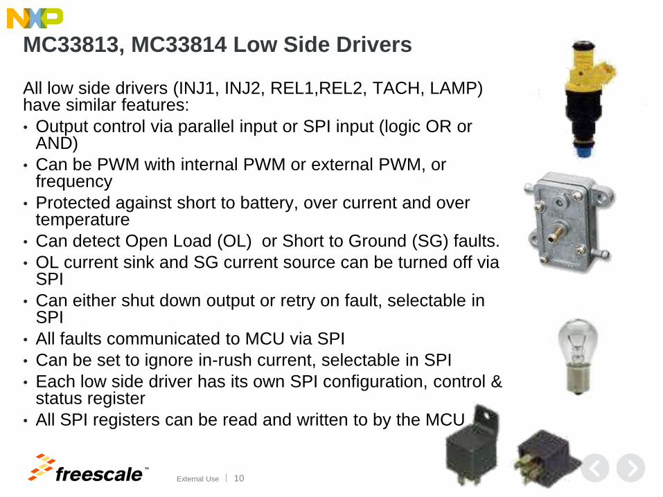
MC33813, MC33814 Low Side Drivers
All low side drivers (INJ1, INJ2, REL1,REL2, TACH, LAMP) have similar features:
• Output control via parallel input or SPI input (logic OR or AND)
• Can be PWM with internal PWM or external PWM, or frequency
• Protected against short to battery, over current and over temperature
• Can detect Open Load (OL) or Short to Ground (SG) faults.
• OL current sink and SG current source can be turned off via SPI
• Can either shut down output or retry on fault, selectable in SPI
• All faults communicated to MCU via SPI
• Can be set to ignore in-rush current, selectable in SPI
• Each low side driver has its own SPI configuration, control & status register
• All SPI registers can be read and written to by the MCU
TM
External Use 11
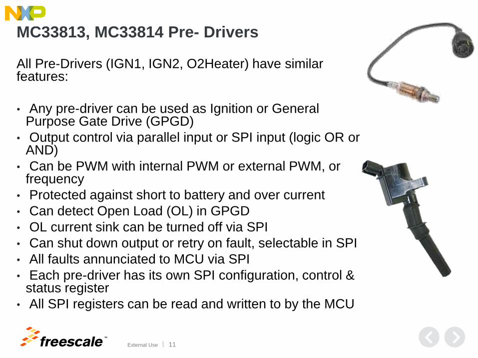
MC33813, MC33814 Pre- Drivers
All Pre-Drivers (IGN1, IGN2, O2Heater) have similar features:
• Any pre-driver can be used as Ignition or General Purpose Gate Drive (GPGD)
• Output control via parallel input or SPI input (logic OR or AND)
• Can be PWM with internal PWM or external PWM, or frequency
• Protected against short to battery and over current
• Can detect Open Load (OL) in GPGD
• OL current sink can be turned off via SPI
• Can shut down output or retry on fault, selectable in SPI
• All faults annunciated to MCU via SPI
• Each pre-driver has its own SPI configuration, control & status register
• All SPI registers can be read and written to by the MCU
TM
External Use 12
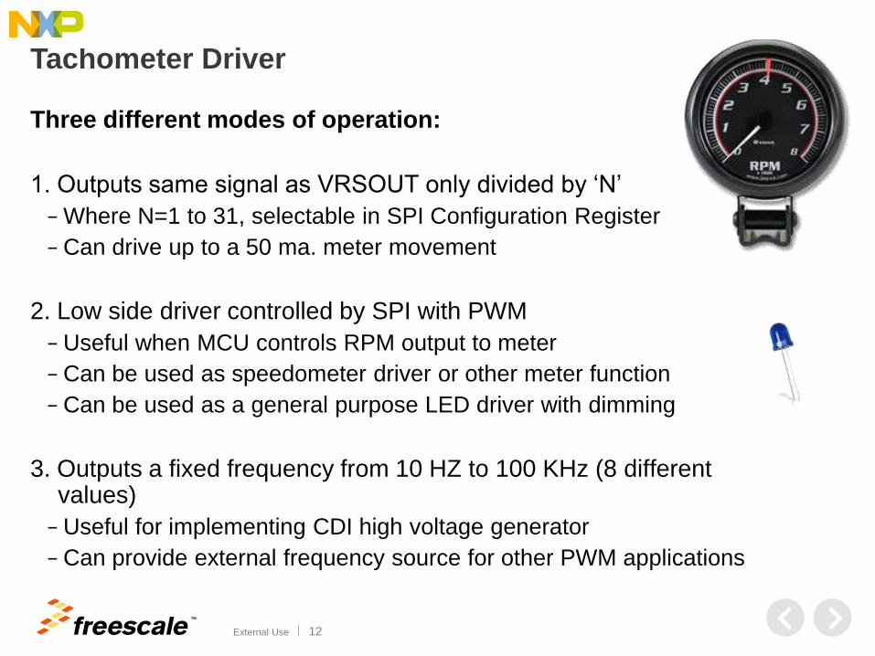
Tachometer Driver
Three different modes of operation:
1. Outputs same signal as VRSOUT only divided by ‘N’
− Where N=1 to 31, selectable in SPI Configuration Register
− Can drive up to a 50 ma. meter movement
2. Low side driver controlled by SPI with PWM
− Useful when MCU controls RPM output to meter
− Can be used as speedometer driver or other meter function
− Can be used as a general purpose LED driver with dimming
3. Outputs a fixed frequency from 10 HZ to 100 KHz (8 different values)
− Useful for implementing CDI high voltage generator
− Can provide external frequency source for other PWM applications
TM
External Use 13
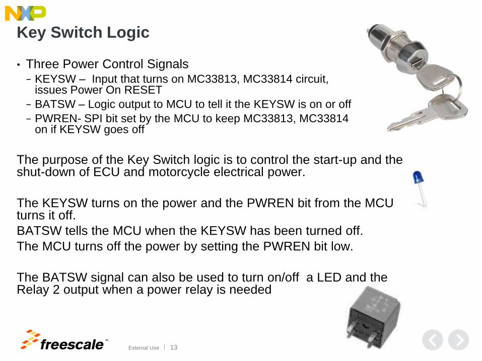
Key Switch Logic
• Three Power Control Signals − KEYSW – Input that turns on MC33813, MC33814 circuit,
issues Power On RESET
− BATSW – Logic output to MCU to tell it the KEYSW is on or off
− PWREN- SPI bit set by the MCU to keep MC33813, MC33814 on if KEYSW goes off
The purpose of the Key Switch logic is to control the start-up and the shut-down of ECU and motorcycle electrical power.
The KEYSW turns on the power and the PWREN bit from the MCU turns it off.
BATSW tells the MCU when the KEYSW has been turned off.
The MCU turns off the power by setting the PWREN bit low.
The BATSW signal can also be used to turn on/off a LED and the Relay 2 output when a power relay is needed
TM
External Use 14
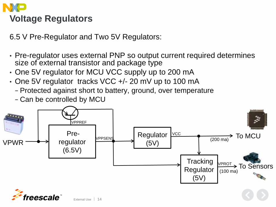
Voltage Regulators
6.5 V Pre-Regulator and Two 5V Regulators:
• Pre-regulator uses external PNP so output current required determines size of external transistor and package type
• One 5V regulator for MCU VCC supply up to 200 mA
• One 5V regulator tracks VCC +/- 20 mV up to 100 mA − Protected against short to battery, ground, over temperature
− Can be controlled by MCU
Pre-
regulator
(6.5V) VPWR
Regulator
(5V) To MCU
Tracking
Regulator
(5V)
To Sensors
VPPREF
VPPSENS VCC
VPROT
(200 ma)
(100 ma)
TM
External Use 15
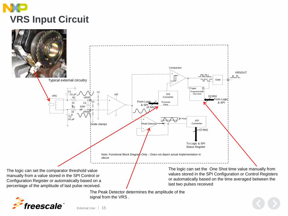
VRS Input Circuit
Differential
Input
+
-
. Peak Detector
v10
A/D
Converter
+
-
D/A
Converter
Comparator
Programmable
One-Shot
15
K
15
K
1000
pF
.01 µF
.01 µF
Note: Functional Block Diagram Only – Does not depict actual implementation in
silicon
Typical external circuitry
.
Diode clamps
V Peak
To Logic & SPI
Status Register
Threshold
Value
Gate
(3 bits)
From Logic
& SPI
(4 bits)
(4 bits)
From Logic
& SPI
Trigger
.
Q
The logic can set the comparator threshold value
manually from a value stored in the SPI Control or
Configuration Register or automatically based on a
percentage of the amplitude of last pulse received.
The logic can set the One Shot time value manually from
values stored in the SPI Configuration or Control Registers
or automatically based on the time averaged between the
last two pulses received.
VRSPVRS
VRSN
VCC
VCC+
-
R1
R2
C1
C2
C3
VRSOUT
The Peak Detector determines the amplitude of the
signal from the VRS .
TM
External Use 16
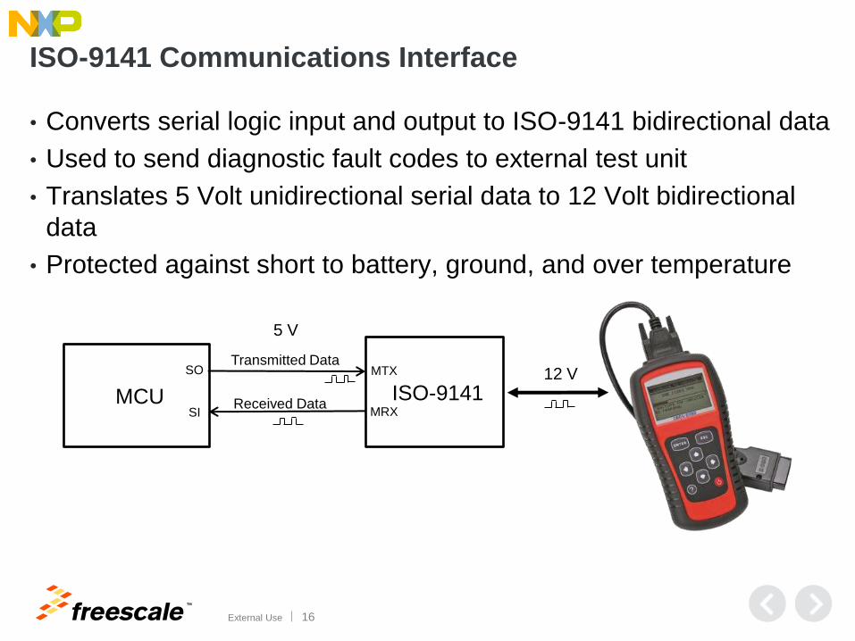
ISO-9141 Communications Interface
• Converts serial logic input and output to ISO-9141 bidirectional data
• Used to send diagnostic fault codes to external test unit
• Translates 5 Volt unidirectional serial data to 12 Volt bidirectional
data
• Protected against short to battery, ground, and over temperature
MCU ISO-9141
MTX Transmitted Data
Received Data MRX
SO
SI
5 V
12 V
TM
External Use 17
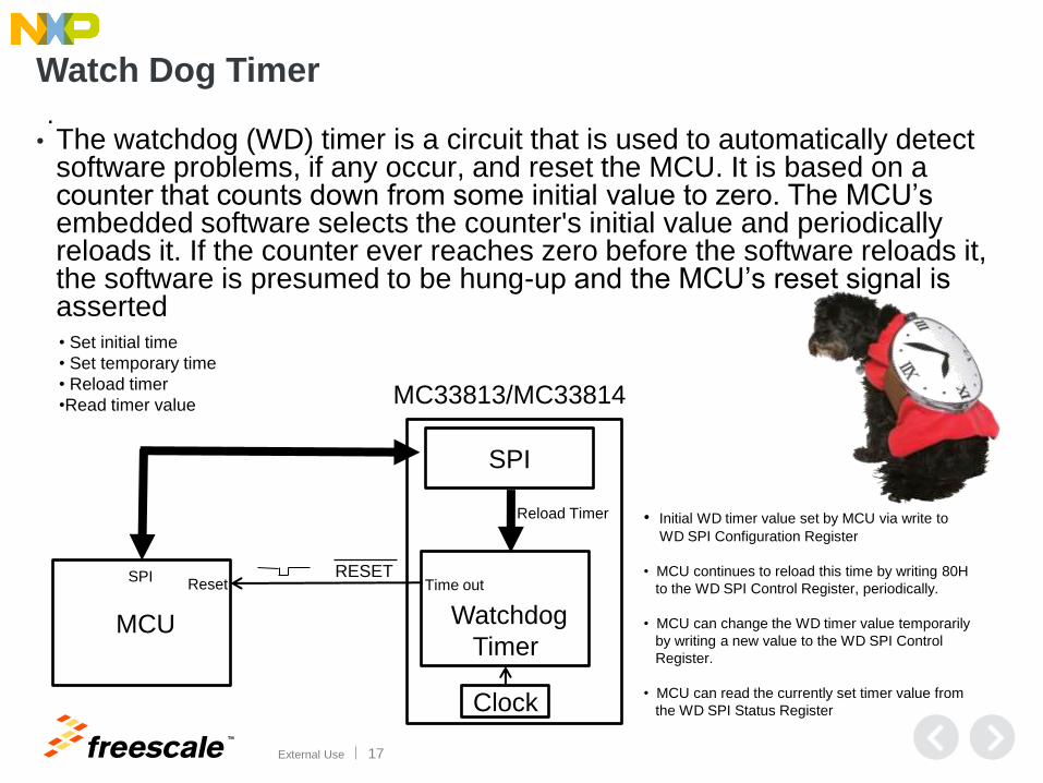
Watch Dog Timer
• The watchdog (WD) timer is a circuit that is used to automatically detect software problems, if any occur, and reset the MCU. It is based on a counter that counts down from some initial value to zero. The MCU’s embedded software selects the counter's initial value and periodically reloads it. If the counter ever reaches zero before the software reloads it, the software is presumed to be hung-up and the MCU’s reset signal is asserted
.
MCU Watchdog
Timer
Reload Timer
• Set initial time
• Set temporary time
• Reload timer
•Read timer value
RESET Reset
SPI
SPI Time out
MC33813/MC33814
Clock
• Initial WD timer value set by MCU via write to
WD SPI Configuration Register
• MCU continues to reload this time by writing 80H
to the WD SPI Control Register, periodically.
• MCU can change the WD timer value temporarily
by writing a new value to the WD SPI Control
Register.
• MCU can read the currently set timer value from
the WD SPI Status Register
TM
External Use 18
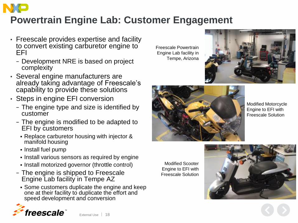
Powertrain Engine Lab: Customer Engagement
• Freescale provides expertise and facility to convert existing carburetor engine to EFI
− Development NRE is based on project complexity
• Several engine manufacturers are already taking advantage of Freescale’s capability to provide these solutions
• Steps in engine EFI conversion
− The engine type and size is identified by customer
− The engine is modified to be adapted to EFI by customers
Replace carburetor housing with injector & manifold housing
Install fuel pump
Install various sensors as required by engine
Install motorized governor (throttle control)
− The engine is shipped to Freescale Engine Lab facility in Tempe AZ
Some customers duplicate the engine and keep one at their facility to duplicate the effort and speed development and conversion
Modified Motorcycle
Engine to EFI with
Freescale Solution
Modified Scooter
Engine to EFI with
Freescale Solution
Freescale Powertrain
Engine Lab facility in
Tempe, Arizona
TM
External Use 19
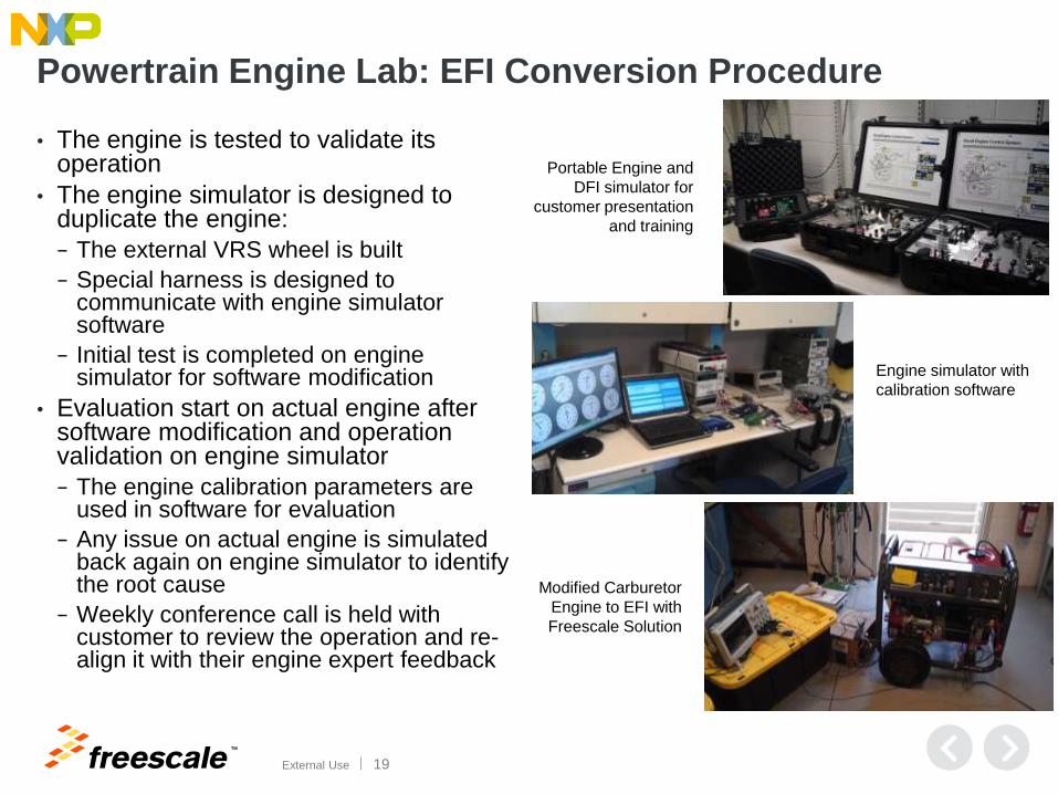
Powertrain Engine Lab: EFI Conversion Procedure
• The engine is tested to validate its operation
• The engine simulator is designed to duplicate the engine:
− The external VRS wheel is built
− Special harness is designed to communicate with engine simulator software
− Initial test is completed on engine simulator for software modification
• Evaluation start on actual engine after software modification and operation validation on engine simulator
− The engine calibration parameters are used in software for evaluation
− Any issue on actual engine is simulated back again on engine simulator to identify the root cause
− Weekly conference call is held with customer to review the operation and re-align it with their engine expert feedback
Engine simulator with
calibration software
Portable Engine and
DFI simulator for
customer presentation
and training
Modified Carburetor
Engine to EFI with
Freescale Solution
TM
External Use 20
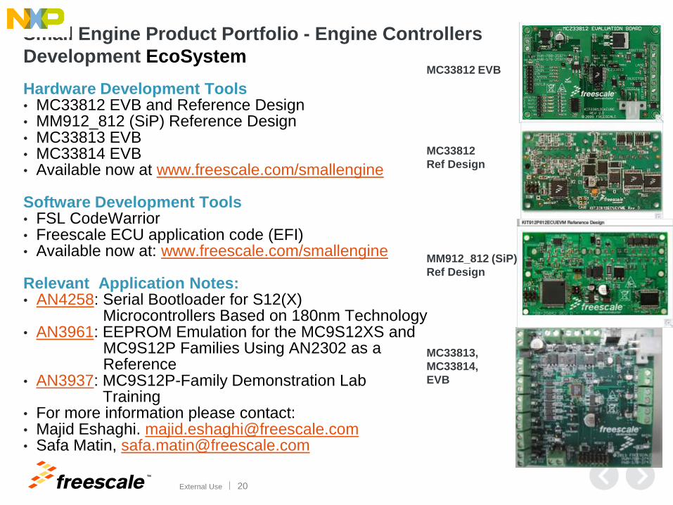
Small Engine Product Portfolio - Engine Controllers
Development EcoSystem MC33812 EVB
MC33812
Ref Design
MM912_812 (SiP)
Ref Design
MC33813,
MC33814,
EVB
Hardware Development Tools • MC33812 EVB and Reference Design • MM912_812 (SiP) Reference Design • MC33813 EVB • MC33814 EVB • Available now at www.freescale.com/smallengine
Software Development Tools • FSL CodeWarrior • Freescale ECU application code (EFI) • Available now at: www.freescale.com/smallengine
Relevant Application Notes: • AN4258: Serial Bootloader for S12(X) Microcontrollers Based on 180nm Technology • AN3961: EEPROM Emulation for the MC9S12XS and MC9S12P Families Using AN2302 as a Reference • AN3937: MC9S12P-Family Demonstration Lab Training • For more information please contact: • Majid Eshaghi. [email protected] • Safa Matin, [email protected]

TM
© 2014 Freescale Semiconductor, Inc. | External Use
www.Freescale.com