skp engineering college -...
TRANSCRIPT
S.K.P. Engineering College, Tiruvannamalai V SEM
Electrical and Electronics Engineering Department 1 Electrical Machines - II
SKP Engineering College
Tiruvannamalai – 606611
A Course Material
on
High Voltage Engineering
By
Mr.M.Karunakaran
Assistant Professor
Electrical and Electronics Engineering Department
S.K.P. Engineering College, Tiruvannamalai V SEM
Electrical and Electronics Engineering Department 2 Electrical Machines - II
Quality Certificate
This is to Certify that the Electronic Study Material
Subject Code:EE6701
Subject Name: High Voltage Engineering
Year/Sem:IV/VII
Being prepared by me and it meets the knowledge requirement of the University
curriculum.
Signature of the Author
Name: Mr.M.Karunakaran
Designation: Assistant Professor
This is to certify that the course material being prepared by Mr. M.Karunakaran is of the
adequate quality. He has referred more than five books and one among them is from
abroad author.
Signature of HD Signature of the Principal
Name: Mrs.R.Sridevi Name: Dr.V.Subramania Bharathi
Seal: Seal:
S.K.P. Engineering College, Tiruvannamalai V SEM
Electrical and Electronics Engineering Department 3 Electrical Machines - II
EE6701 HIGH VOLTAGE ENGINEERING LT P C 3 0 0 3
OBJECTIVES:
To understand the various types of over voltages in power system and protection methods.
Generation of over voltages in laboratories.
Measurement of over voltages.
Nature of Breakdown mechanism in solid, liquid and gaseous dielectrics.
Testing of power apparatus and insulation coordination.
UNIT I OVER VOLTAGES IN ELECTRICAL POWER SYSTEMS 9
Causes of over voltages and its effects on power system – Lightning, switching surges and
temporaryovervoltages, Corona and its effects – Reflection and Refraction of Travelling waves-
Protectionagainst overvoltages.
UNIT II DIELECTRIC BREAKDOWN 9
Gaseous breakdown in uniform and non-uniform fields – Corona discharges – Vacuum
breakdown –Conduction and breakdown in pure and commercial liquids, Maintenance of oil
Quality – Breakdown mechanisms in solid and composite dielectrics.
UNIT III GENERATION OF HIGH VOLTAGES AND HIGH CURRENTS 9
Generation of High DC, AC, impulse voltages and currents - Triggering and control of impulse
generators.
UNIT IV MEASUREMENT OF HIGH VOLTAGES AND HIGH CURRENTS 9
High Resistance with series ammeter – Dividers, Resistance, Capacitance and Mixed dividers –
Peak Voltmeter, Generating Voltmeters - Capacitance Voltage Transformers, Electrostatic
Voltmeters – Sphere Gaps - High current shunts- Digital techniques in high voltage
measurement.
S.K.P. Engineering College, Tiruvannamalai V SEM
Electrical and Electronics Engineering Department 4 Electrical Machines - II
UNIT V HIGH VOLTAGE TESTING & INSULATION COORDINATION 9
High voltage testing of electrical power apparatus as per International and Indian standards –
Power frequency, impulse voltage and DC testing of Insulators, circuit breakers, bushing,
isolators and transformers- Insulation Coordination. TOTAL : 45 PERIODS
OUTCOMES:
Ability to understand and analyze power system operation, stability, control and protection.
TEXT BOOKS:
1. S.Naidu and V. Kamaraju, ‘High Voltage Engineering’, Tata McGraw Hill, Fifth Edition, 2013.
2. E. Kuffel and W.S. Zaengl, J.Kuffel, ‘High voltage Engineering fundamentals’, Newnes
Second Edition Elsevier , New Delhi, 2005.
3. Subir Ray,’ An Introduction to High Voltage Engineering’ PHI Learning Private Limited, New
REFERENCES:
1. L.L. Alston, ‘High Voltage Technology’, Oxford University Press, First Indian Edition, 2011.
2. C.L. Wadhwa, ‘High voltage Engineering’, New Age International Publishers, Third Edition,
2010.
S.K.P. Engineering College, Tiruvannamalai V SEM
Electrical and Electronics Engineering Department 5 Electrical Machines - II
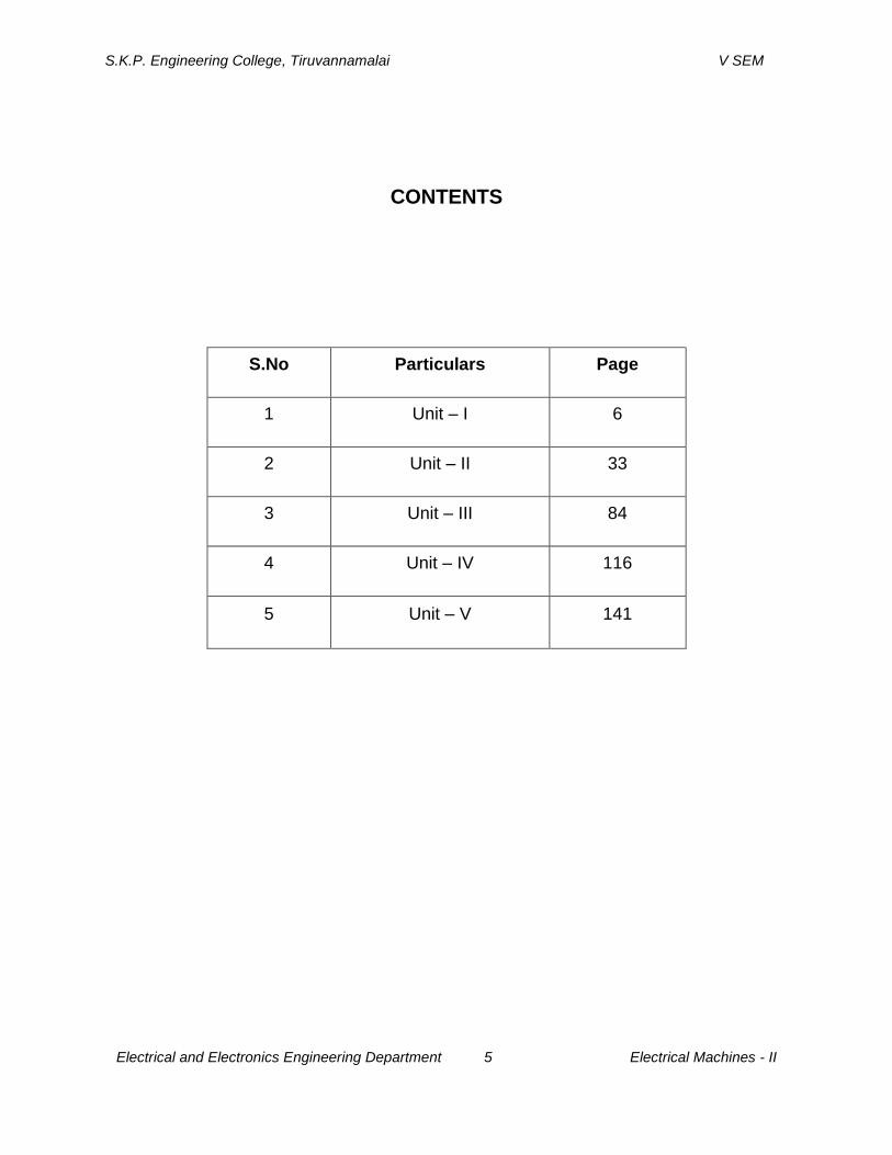
CONTENTS
S.No Particulars Page
1 Unit – I 6
2 Unit – II 33
3 Unit – III 84
4 Unit – IV 116
5 Unit – V 141
S.K.P. Engineering College, Tiruvannamalai V SEM
Electrical and Electronics Engineering Department 6 Electrical Machines - II
UNIT-I
OVER VOLTAGES IN ELECTRICAL POWER SYSTEMS
PART A
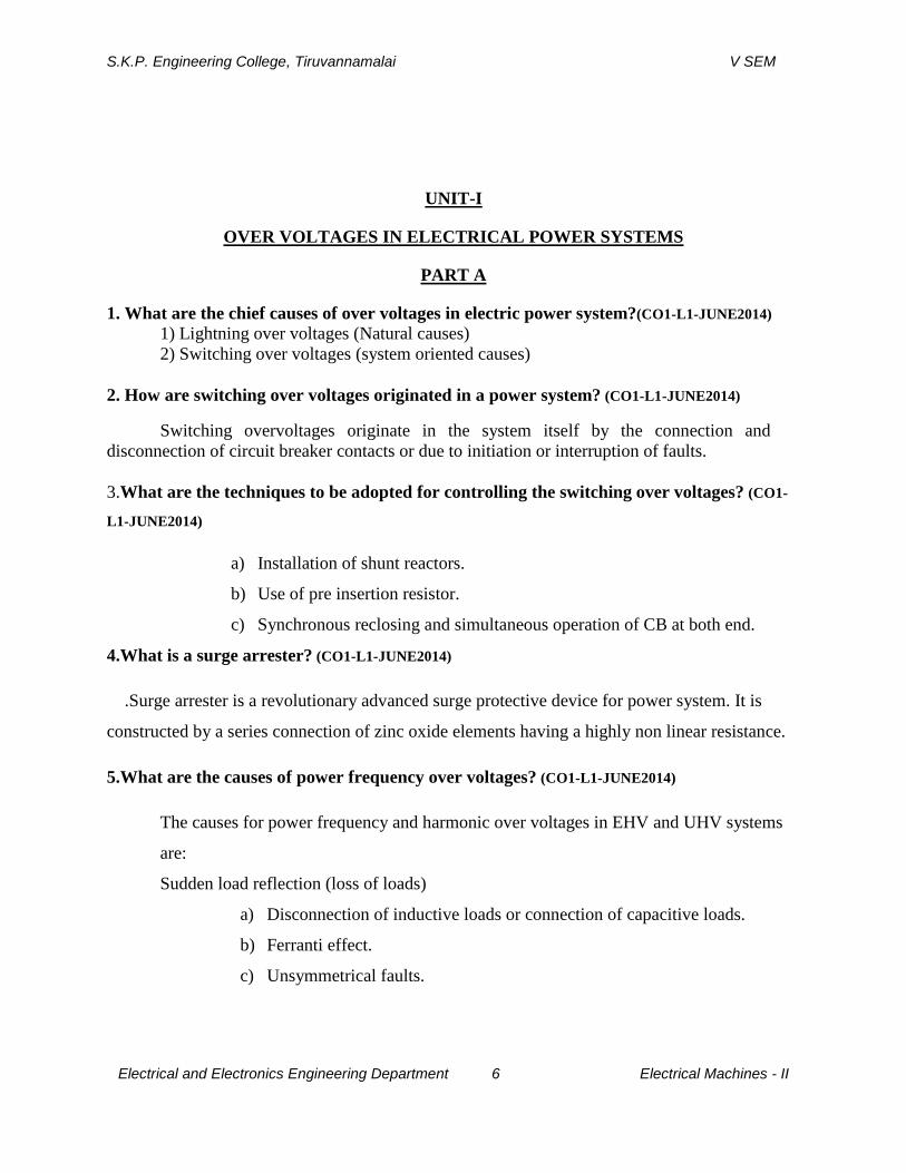
1. What are the chief causes of over voltages in electric power system?(CO1-L1-JUNE2014)
1) Lightning over voltages (Natural causes)
2) Switching over voltages (system oriented causes)
2. How are switching over voltages originated in a power system? (CO1-L1-JUNE2014)
Switching overvoltages originate in the system itself by the connection and
disconnection of circuit breaker contacts or due to initiation or interruption of faults.
3.What are the techniques to be adopted for controlling the switching over voltages? (CO1-
L1-JUNE2014)
a) Installation of shunt reactors.
b) Use of pre insertion resistor.
c) Synchronous reclosing and simultaneous operation of CB at both end.
4.What is a surge arrester? (CO1-L1-JUNE2014)
.Surge arrester is a revolutionary advanced surge protective device for power system. It is
constructed by a series connection of zinc oxide elements having a highly non linear resistance.
5.What are the causes of power frequency over voltages? (CO1-L1-JUNE2014)
The causes for power frequency and harmonic over voltages in EHV and UHV systems
are:
Sudden load reflection (loss of loads)
a) Disconnection of inductive loads or connection of capacitive loads.
b) Ferranti effect.
c) Unsymmetrical faults.
S.K.P. Engineering College, Tiruvannamalai V SEM
Electrical and Electronics Engineering Department 7 Electrical Machines - II
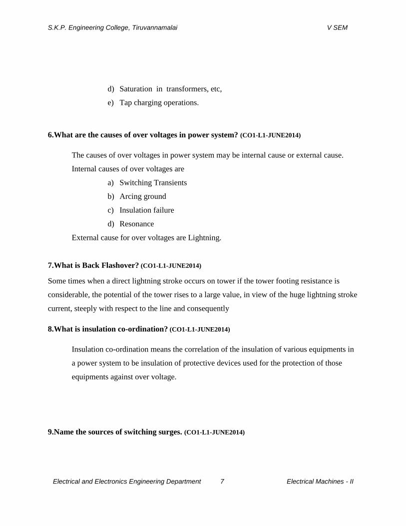
d) Saturation in transformers, etc,
e) Tap charging operations.
6.What are the causes of over voltages in power system? (CO1-L1-JUNE2014)
The causes of over voltages in power system may be internal cause or external cause.
Internal causes of over voltages are
a) Switching Transients
b) Arcing ground
c) Insulation failure
d) Resonance
External cause for over voltages are Lightning.
7.What is Back Flashover? (CO1-L1-JUNE2014)
Some times when a direct lightning stroke occurs on tower if the tower footing resistance is
considerable, the potential of the tower rises to a large value, in view of the huge lightning stroke
current, steeply with respect to the line and consequently
8.What is insulation co-ordination? (CO1-L1-JUNE2014)
Insulation co-ordination means the correlation of the insulation of various equipments in
a power system to be insulation of protective devices used for the protection of those
equipments against over voltage.
9.Name the sources of switching surges. (CO1-L1-JUNE2014)
S.K.P. Engineering College, Tiruvannamalai V SEM
Electrical and Electronics Engineering Department 8 Electrical Machines - II
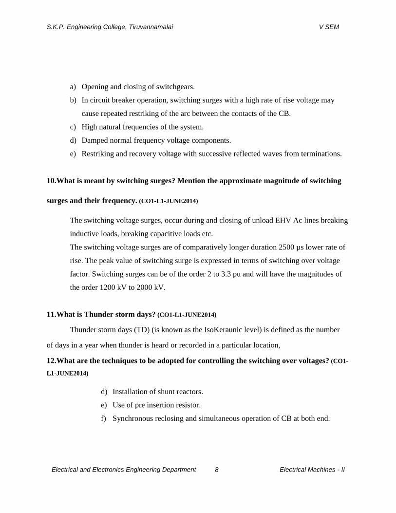
a) Opening and closing of switchgears.
b) In circuit breaker operation, switching surges with a high rate of rise voltage may
cause repeated restriking of the arc between the contacts of the CB.
c) High natural frequencies of the system.
d) Damped normal frequency voltage components.
e) Restriking and recovery voltage with successive reflected waves from terminations.
10.What is meant by switching surges? Mention the approximate magnitude of switching
surges and their frequency. (CO1-L1-JUNE2014)
The switching voltage surges, occur during and closing of unload EHV Ac lines breaking
inductive loads, breaking capacitive loads etc.
The switching voltage surges are of comparatively longer duration 2500 µs lower rate of
rise. The peak value of switching surge is expressed in terms of switching over voltage
factor. Switching surges can be of the order 2 to 3.3 pu and will have the magnitudes of
the order 1200 kV to 2000 kV.
11.What is Thunder storm days? (CO1-L1-JUNE2014)
Thunder storm days (TD) (is known as the IsoKeraunic level) is defined as the number
of days in a year when thunder is heard or recorded in a particular location,
12.What are the techniques to be adopted for controlling the switching over voltages? (CO1-
L1-JUNE2014)
d) Installation of shunt reactors.
e) Use of pre insertion resistor.
f) Synchronous reclosing and simultaneous operation of CB at both end.
S.K.P. Engineering College, Tiruvannamalai V SEM
Electrical and Electronics Engineering Department 9 Electrical Machines - II
g) Use of surge arrester and elimination of trapped charges by line shunting
after opening by means of earthling switch.
h) Use of surge absorber or resistance switching.
13.What are ground rods? (CO1-L1-JUNE2014)
Additional rods provided driven into the ground near the tower footing and
connected to the tower footing to reduce the tower footing resistance [15 mm dia, 3.0 m
long, 10 to 16 rods]
PART B
S.K.P. Engineering College, Tiruvannamalai V SEM
Electrical and Electronics Engineering Department 10 Electrical Machines - II
1.Show the charge distribution pattern in the cloud following wilson and simpson theory.
(CO1-L1-JUNE2014)
LIGHTNING PHENOMENON
Lightning phenomenon is a peak discharge in which charge accumulated in the clouds
discharges into a neighbouring cloud or to the ground. The electrode separation, i.e.cloud-to-
cloud or cloud-to-ground is very large, perhaps 10 km or more. The mechanism of charge
formation in the clouds and their discharges is quite a complicated and uncertain process.
Nevertheless, a lot of information has been collected since the last fifty years and several theories
have been put forth for explaining the phenomenon
Charge Formation in the Clouds
The factors that contribute to the formation or accumulation of charge in the clouds are
too many and uncertain. But during thunderstorms, positive and negative charges become
separated by the heavy air currents with ice crystals in the upper part and rain in the lower parts
of the cloud. This charge separation depends on the height of the clouds, which range from 200
to 10,000 m, with their charge centres probably at a distance of about 300 to 2000 m. The
volume of the clouds that participate in lightning flashover are uncertain, but the charge inside
the cloud may be as high as 1 to 100 C.Clouds may have a potential as high as 107 to 108 V with
field gradients ranging from100 V/cm within the cloud to as high as 10 kV/cm at the initial
discharge point The energies associated with the cloud discharges can be as high as 250 kWh. It
is believed that the upper regions of the cloud are usually positively charged, whereas the lower
region and the base are predominantly negative except the local region, near the base and the
head, which is positive. The maximum gradient reached at the ground level due to a charged
cloud may be as high as 300 V/cm, while the fair weather gradients are about 1 V/cm. A
probable charge distribution model is given in Fig. with the corresponding field gradients near
the ground.According to the Simpson's theory (Fig. 8.2) there are three essential regions in the
cloud to be considered for charge formation. Below region A, air currents travel Ground Cloud
motion Field gradient at ground above 800 cm/s, and no raindrops fall through. In region A, air
velocity is high enough to break the falling raindrops causing a positive charge spray in the cloud
and negative charge in the air The spray is blown upwards, but as the velocity of air decreases,
the positively charged water drops recombine with the larger drops and fall again

S.K.P. Engineering College, Tiruvannamalai V SEM
Electrical and Electronics Engineering Department 11 Electrical Machines - II
Thus region A, eventually becomes predominantly positively charged, while region B
above it, becomes negatively charged by air currents. In the upper regions in the cloud,the
temperature is low (below freezing point) and only ice crystals exist The impact of air on these
crystals makes them negatively charged, thus the distribution of the charge within the cloud
becomes as shown in Fig.
Cloud model according to Simpson's theory
However, the above theory is obsolete and the explanation presented is not satisfactory.
Recently, Reynolds and Mason proposed modification, according to which the thunder clouds
are developed at heights 1 to 2 km above the ground level and may extend up to 12 to 14 km
above the ground. For thunder clouds and charge formation air currents, moisture and specific
temperature range are required.The air currents controlled by the temperature gradient move
upwards carrying moisture and water droplets. The temperature is 00C at about 4 km from the
ground and may reach - 500C at about 12 km height. But water droplets do not freeze as soon as
the temperature is 00C. They freeze below - 40
0 C only as solid particles on which crystalline ice
patterns develop and grow. The larger the number of solid sites or nuclei present, the higher is
the temperature (> -400C) at which the ice crystals grow.Thus in clouds, the effective freezing
S.K.P. Engineering College, Tiruvannamalai V SEM
Electrical and Electronics Engineering Department 12 Electrical Machines - II
temperature range is around - 330C to - 4O0C.The water droplets in the thunder cloud are blown
up by air currents and get super cooled over a range of heights and temperatures.
When such freezing occurs, the crystals grow into large masses and due to their weight
and gravitational force start moving downwards. Thus, a thunder cloud consists of super cooled
water droplets moving upwards and large hail stones moving downwards.
When the upward moving super cooled water droplets act on cooler hail stone, it freezes
partially, i.e. the outer layer of the water droplets freezes forming a shell with water inside. When
the process of cooling extends to inside warmer water in the core ,it expands, thereby splintering
and spraying the frozen ice shell. The splinters being fine in size are moved up by the air currents
and carry a net positive charge to the upper region of the cloud. The hail stones that travel
onwards carry an equivalent Negative rain Positive rain Air currents Cloud motion Ice crystals
negative charge to the lower regions of the cloud and thus negative charge builds upin the bottom
side of the cloud.According to Mason, the ice splinters should carry only positive charge
upwards.Water being ionic in nature has concentration of H+ and OH
- ions. The ion density
depends on the temperature. Thus, in an ice slab with upper and lower surfaces at temperatures
T1 and T2, (T1< T2, there will be a higher concentration of ions in the below region. However,
since H+ ions are much lighter, they diffuse much faster allover the volume. Therefore, the lower
portion which is warmer will have a net negative charge density, and hence the upper portion, i.e.
cooler region will have a net positive charge density. Hence, it must be appreciated, that the
outer shells of the freezed water droplets coming into contact with hail stones will be relatively
cooler(than their inner core—warmer water) and therefore acquire a net positive charge.When
the shell splinters, the charge carried by them in the upward direction is positive.According to
the Reynold's theory, which is based on experimental results, the hail packets get negatively
charged when impinged upon by warmer ice crystals. When the temperature conditions are
reversed, the charging polarity reverses. However, the extent of the charging and consequently
the rate of charge generation was found to disagree with the practical observations relating to
thunder clouds. This type of phenomenon also occurs in thunder clouds.
2.Explain the mechanism of Lightning with neat diagrams. (CO1-L1-JUNE2014)
Mechanism of Lightning Stroke
Lightning phenomenon is the discharge of the cloud to the ground. The cloud and the
ground form two plates of a gigantic capacitor and the dielectric medium is air. Since the lower
part of the cloud is negatively charged, the earth is positively charged by induction. Lightning
discharge will require the puncture of the air between the cloud and the earth. For breakdown of
air at STP condition the electric field required is 30 kV/cm peak. But in a cloud where the
moisture content in the air is large and also because of the high altitude (lower pressure) it is seen

S.K.P. Engineering College, Tiruvannamalai V SEM
Electrical and Electronics Engineering Department 13 Electrical Machines - II
that for breakdown of air the electric field required is only 10 kV/cm.After a gradient of
approximately 10 kV/cm is set up in the cloud, the air surrounding gets ionized.
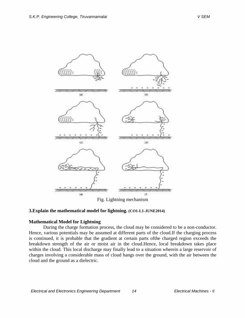
At this a streamer (Fig. ) starts from the cloud towards the earth which cannot be detected with
the naked eye; only a spot travelling is detected. The current in the streamer is of the order of 100
amperes and the speed of the streamer is 0.16 m/µ sec. This streamer is known as pilot streamer
because this leads to the lightning phenomenon.
Depending upon the state of ionization of the air surrounding the streamer, it is branched
to several paths and this is known as stepped leader (Fig.). The leader steps are of the order of 50
m in length and are accomplished in about a microsecond.The charge is brought from the cloud
through the already ionized path to these pauses. The air surrounding these pauses is again
ionized and the leader in this way reaches the earth (Fig. (c)).Once the stepped leader has made
contact with the earth it is believed that a power return stroke(Fig. (c)) moves very fast up
towards the cloud through the already ionized path by the leader.
This streamer is very intense where the current varies between 1000 amps and 200,000
amps and the speedis about 10% that of light. It is here where the –ve charge of the cloud is
being neutralized by the positive induced charge on the earth (Fig. 7.24(d)). It is this instant
which gives rise to lightning flash which we observe with our naked eye.
There may be another cell of charges in the cloud near the neutralized charged cell. This
charged cell will try to neutralize through this ionised path. This streamer is known as dart leader
(Fig. 7.24(e)). The velocity of the dart leader is about 3% of the velocity of light. The effect of
the dart leader is much more severe than that of the return stroke.The discharge current in the
return streamer is relatively very large but as it lasts only for a few microseconds the energy
contained in the streamer is small and hence this streamer is known as cold lightning stroke
whereas the dart leader is known as hot lightning stroke because even though the current in this
leader is relatively smaller but it lasts for some milliseconds and therefore the energy contained
in this leader is relatively larger.
It is found that each thunder cloud may contain as many as 40 charged cells and a heavy
lightning stroke may occur. This is known as multiple stroke.
S.K.P. Engineering College, Tiruvannamalai V SEM
Electrical and Electronics Engineering Department 14 Electrical Machines - II
Fig. Lightning mechanism
3.Explain the mathematical model for lightning. (CO1-L1-JUNE2014)
Mathematical Model for Lightning
During the charge formation process, the cloud may be considered to be a non-conductor.
Hence, various potentials may be assumed at different parts of the cloud.If the charging process
is continued, it is probable that the gradient at certain parts ofthe charged region exceeds the
breakdown strength of the air or moist air in the cloud.Hence, local breakdown takes place
within the cloud. This local discharge may finally lead to a situation wherein a large reservoir of
charges involving a considerable mass of cloud hangs over the ground, with the air between the
cloud and the ground as a dielectric.
S.K.P. Engineering College, Tiruvannamalai V SEM
Electrical and Electronics Engineering Department 15 Electrical Machines - II
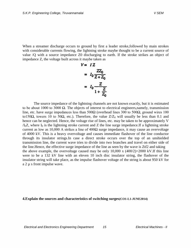
When a streamer discharge occurs to ground by first a leader stroke,followed by main strokes
with considerable currents flowing, the lightning stroke maybe thought to be a current source of
value /Q with a source impedance Z0 discharging to earth. If the stroke strikes an object of
impedance Z, the voltage built across it maybe taken as
The source impedance of the lightning channels are not known exactly, but it is estimated
to be about 1000 to 3000 Ω. The objects of interest to electrical engineers,namely, transmission
line, etc. have surge impedances less than 500Ω (overhead lines 300 to 500Ω, ground wires 100
to150Ω, towers 10 to 50Ω, etc.). Therefore, the value Z/Z0 will usually be less than 0.1 and
hence can be neglected. Hence, the voltage rise of lines, etc. may be taken to be approximately V
/I0Z, where I0 is the lightning stroke current and Z the line surge impedance.If a lightning stroke
current as low as 10,000 A strikes a line of 400Ω surge impedance, it may cause an overvoltage
of 4000 kV. This is a heavy overvoltage and causes immediate flashover of the line conductor
through its insulator strings.In case a direct stroke occurs over the top of an unshielded
transmission line, the current wave tries to divide into two branches and travel on either side of
the line.Hence, the effective surge impedance of the line as seen by the wave is Ztf2 and taking
the above example, the overvoltage caused may be only 10,000 x (400/2)=2000 kV.If this line
were to be a 132 kV line with an eleven 10 inch disc insulator string, the flashover of the
insulator string will take place, as the impulse flashover voltage of the string is about 950 kV for
a 2 µ s front impulse wave.
4.Explain the sources and characteristics of switching surges(CO1-L1-JUNE2014)

S.K.P. Engineering College, Tiruvannamalai V SEM
Electrical and Electronics Engineering Department 16 Electrical Machines - II
OVERVOLTAGE DUE TO SWITCHING SURGES,
Origin of Switching Surges
The making and breaking of electric circuits with switchgear may result in abnormal
overvoltages in power systems having large inductances and capacitances. The overvoltages may
go as high as six times the normal power frequency voltage. In circuit breaking operation,
switching surges with a high rate of rise of voltage may cause repeated restriking of the arc
between the contacts of a circuit breaker, there by using destruction of the circuit breaker
contacts.
The switching surges may include high natural frequencies of the system, a damped normal
frequency voltage component, or the restriking and recovery voltage of the system with
successive reflected waves from terminations.
Characteristics of Switching Surges
The waveshapes of switching surges are quite different and may have origin from any
of the following sources.
(i) De-energizing of transmission lines, cables, shunt capacitor, banks, etc.
(ii) Disconnection of unloaded transformers, reactors, etc.
(iii) Energization or reclosing of lines and reactive loads,
(iv) Sudden switching off of loads.
(v) Short circuits and fault clearances.
(vi) Resonance phenomenon like ferro-resonance, arcing grounds, etc. Typical waveshapes of the
switching surges are given in Figs. 8.16a to (e).From the figures of the switching surges it is
clear that the overvoltages are irregular (oscillatory or unipolar) and can be of high frequency or
power frequency with its harmonics. The relative magnitudes of the overvoltages may be about
2.4 p.u.in the case of transformer energizing and 1.4 to 2.0 p.u. in switching transmission
lines.
Switching OvervoltagesIn EHV and UHV Systems

S.K.P. Engineering College, Tiruvannamalai V SEM
Electrical and Electronics Engineering Department 17 Electrical Machines - II
The insulation has the lowest strength for switching surges with regard to long airgaps.
Further, switching overvoltages are of relatively higher magnitudes as compared to the lightning
overvoltages for UHV systems. Overvoltages are generated in EHV systems when there is a
sudden release of internal energy stored either in the electrostatic form (in the capacitance) or in
the electromagnetic form (in the inductance). The different situations under which this happens
are summarized as
S.K.P. Engineering College, Tiruvannamalai V SEM
Electrical and Electronics Engineering Department 18 Electrical Machines - II
(i) interruption of low inductive currents (current chopping) by high speed circuit breakers.
This occurs when the transformers or reactors are switched off
(ii)interruption of small capacitive currents, such as switching off of unloaded lines etc.
(ii) ferro-resonance condition This may occur when poles of a circuit breaker do not close
simultaneously
(iv) energization of long EHV or UHV lines.
Transient overvoltages in the above cases can be of the order of 2.0 to 3.3 p.u. and will
have magnitudes of the order of 1200 kV to 2000 kV on 750 kV systems. The duration of these
overvoltages varies from 1 to 10 ms depending on the circuit parameters. It is seen that these are
of comparable magnitude or are even higher than those that occur due to lightning. Sometimes
the overvoltages may last for several cycles.
The other situations of switching that give rise to switching overvoltages of shorter duration (0.5
to 5 ms) and lower magnitudes (2.0 to 2.5 p.u.) are:
(a) single pole closing 6f circuit breaker
(b) interruption of fault current when the L-G or L-L fault is cleared
(c) resistance switching used in circuit breakers
(d) switching lines terminated by transformers
(e) series capacitor compensated lines
(f)sparking of the surge diverter located at the receiving end of the line to limit the lightning
Overvoltages
The overvoltages due to the above conditions are studied or calculated from
(a) mathematical modelling of a system using digital computers
(b) scale modelling using transient network analysers
(c) by conducting field tests to determine the expected maximum amplitude of the overvoltages
and their duration at different points on the line. The main factors that are investigated in the
above studies are
(i) the effect of line parameters, series capacitors and shunt reactors on the magnitude and
duration of the transients
(ii) the damping factors needed to reduce the magnitude of overvoltages
(iii) the effect of single pole closing, restriking and switching with series resistorsor circuit
S.K.P. Engineering College, Tiruvannamalai V SEM
Electrical and Electronics Engineering Department 19 Electrical Machines - II
breakers on the overvoltages, and
(iv) the lightning arrester sparkover characteristics.
It is necessary in EHV and UHV systems to control the switching surges to a safe value of less
than 2.5 p.u. or preferably to 2.0 p.u. or even less. The measures taken to control or reduce the
overvoltages are
(i) one step or multi-step energisation of lines by preinsertion of resistors,
(ii) phase controlled closing of circuit breakers with proper sensors,
(iii) drainage of trapped charges on long lines before the reclosing of the lines, and
(iii) limiting the overvoltages by using surge diverters.
5. What are causes of power frequency over voltages in power system. Explain them in
detail. (CO1-L1-JUNE2014)
Power Frequency Overvoltages in Power Systems
The power frequency overvoltages occur in large power systems and they are of much
concern in EHV systems, i.e. systems of 400 kV and above. The main causes for power
frequency and its harmonic overvoltages are
(a) sudden loss of loads,
(b) disconnection of inductive loads or connection of capacitive loads,
(c) Ferranti effect, unsymmetrical faults, and
(d) saturation in transformers, etc.
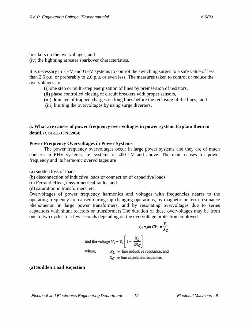
Overvoltages of power frequency harmonics and voltages with frequencies nearer to the
operating frequency are caused during tap changing operations, by magnetic or ferro-resonance
phenomenon in large power transformers, and by resonating overvoltages due to series
capacitors with shunt reactors or transformers.The duration of these overvoltages may be from
one to two cycles to a few seconds depending on the overvoltage protection employed
.
(a) Sudden Load Rejection
S.K.P. Engineering College, Tiruvannamalai V SEM
Electrical and Electronics Engineering Department 20 Electrical Machines - II
Sudden load rejection on large power systems causes the speeding up of generator prime
movers. The speed governors and automatic voltage regulators will intervene to restore normal
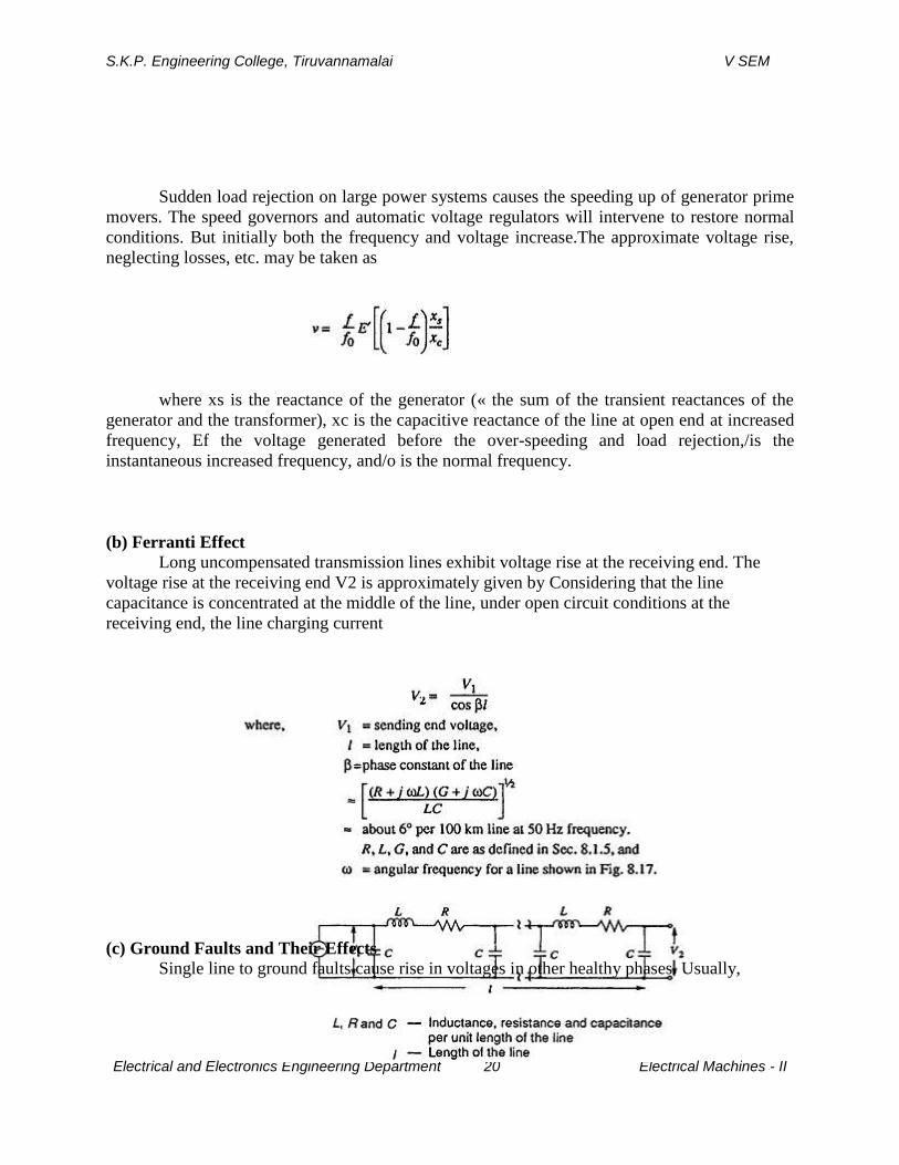
conditions. But initially both the frequency and voltage increase.The approximate voltage rise,
neglecting losses, etc. may be taken as
where xs is the reactance of the generator (« the sum of the transient reactances of the
generator and the transformer), xc is the capacitive reactance of the line at open end at increased
frequency, Ef the voltage generated before the over-speeding and load rejection,/is the
instantaneous increased frequency, and/o is the normal frequency.
(b) Ferranti Effect
Long uncompensated transmission lines exhibit voltage rise at the receiving end. The
voltage rise at the receiving end V2 is approximately given by Considering that the line
capacitance is concentrated at the middle of the line, under open circuit conditions at the
receiving end, the line charging current
(c) Ground Faults and Their Effects
Single line to ground faults cause rise in voltages in other healthy phases. Usually,
S.K.P. Engineering College, Tiruvannamalai V SEM
Electrical and Electronics Engineering Department 21 Electrical Machines - II
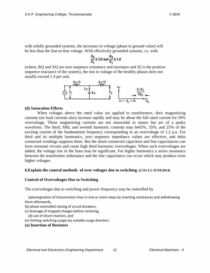
with solidly grounded systems, the increases in voltage (phase to ground value) will
be less than the line-to-line voltage. With effectively grounded systems, i.e. with
(where, RQ and XQ are zero sequence resistance and reactance and X] is the positive
sequence reactance of the system), the rise in voltage of the healthy phases does not
usually exceed 1.4 per unit.
(d) Saturation Effects
When voltages above the rated value are applied to transformers, their magnetizing
currents (no load currents also) increase rapidly and may be about the full rated current for 50%
overvoltage. These magnetizing currents are not sinusoidal in nature but are of a peaky
waveform. The third, fifth, and seventh harmonic contents may be65%, 35%, and 25% of the
exciting current of the fundamental frequency corresponding to an overvoltage of 1.2 p.u. For
third and its multiple harmonics, zero sequence impedance values are effective, and delta
connected windings suppress them. But the shunt connected capacitors and line capacitances can
form resonant circuits and cause high third harmonic overvoltages. When such overvoltages are
added, the voltage rise in the lines may be significant. For higher harmonics a series resonance
between the transformer inductance and the line capacitance can occur which may produce even
higher voltages.
6.Explain the control methods of over voltages due to switching. (CO1-L1-JUNE2014)
Control of Overvoltages Due to Switching
The overvoltages due to switching and power frequency may be controlled by
(a)energization of transmission lines in one or more steps by inserting resistances and withdrawing them afterwards, (b) phase controlled closing of circuit breakers, (c) drainage of trapped charges before reclosing, (d) use of shunt reactors, and (e) limiting switching surges by suitable surge diverters.
(a) Insertion of Resistors
S.K.P. Engineering College, Tiruvannamalai V SEM
Electrical and Electronics Engineering Department 22 Electrical Machines - II
It is normal and a common practice to insert resistances/? in series with circuit breaker
contacts when switching on but short circuiting them after a few cycles. This will reduce the
transients occurring due to switching. The voltage step applied is first reduced to Z0/(R + Z0) per
unit where ZQ is the surge impedance of the line. It is reflected from the far end unchanged and
again reflected back from the near end with reflection factor (R – Z0)/(R + Z0) per unit If R = Z0,
there is no reflection from the far end. The applied step at the first instance is only 0.5 per
unit.When the resistor is short circuited, a voltage step equal to the instantaneous voltage drop
enters the line. If the resistor is kept for a duration larger than 5ms (for50 Hz sine wave = 1/4
cycle duration), it can be shown from successive reflections and transmissions, that the
overvoltage may reach as high as 1.2 p.u. for a line length of 500 km.
But for conventional opening of the breaker, the resistors have too high an ohmic value to
be effective for resistance closing. Therefore, pre-insertion of suitable value resistors in practice
is done to limit the overvoltage to less than 2.0 to 2.5 p.u.Normal time of insertion is 6 to 10 m s.
(b) Phase Controlled Switching
Overvoltages can be avoided by controlling the exact instances of the closing of the three
phases separately. But this necessitates the use of complicated controlling equipment and
therefore is not adopted.
(c) Drainage of Trapped Charge
When lines are suddenly switching off, "electric charge" may be left on capacitorsand
line conductors. This charge will normally leak through the leakage path of theinsulators, etc.
Conventional potential transformers (magnetic) may also help thedrainage of the charge. An
effective way to reduce the trapped charges during the leadtime before reclosing is by temporary
insertion of resistors to ground or in series with shunt reactors and removing before the closure
of the switches.
(d) Shunt Reactors
Normally all EHV lines will have shunt reactors to limit the voltage rise due to the
Ferranti effect. They also help in reducing surges caused due to sudden energizing.However,
shunt reactors cannot drain the trapped charge but will give rise to oscillations with the
capacitance of the system. Since the compensation given by the reactorswill be less than 100%,
the frequency of oscillation will be less than the power frequency and overvoltages produced
may be as high as 1.2 p.u. Resistors in series with these reactors will suppress the oscillations
and limit the overvoltages.
7.What are the different methods employed for lightning protection of overhead lines?
Protection against Lightning Overvoltages and Switching Surges ofshort Duration
S.K.P. Engineering College, Tiruvannamalai V SEM
Electrical and Electronics Engineering Department 23 Electrical Machines - II
Overvoltages due to lightning strokes can be avoided or minimized in practice by
(a) shielding the overhead lines by using ground wires above the phase wires,
(b) using ground rods and counter-poise wires, and
(c) including protective devices like expulsion gaps, protector tubes on the lines,
and surge diverters at the line terminations and substations.
(a) Lightning Protection Using Shielded Wires or Ground Wires
Ground wire is a conductor run parallel to the main conductor of the transmission line
supported on the same tower and earthed at every equally and regularly spaced towers.It is run
above the main conductor of the line. The ground wire shields the transmission line conductor
from induced charges, from clouds as well as from a lightning discharge. The arrangements of
ground wires over the line conductor is shown inFig.The mechanism by which the line is
protected may be explained as follows. If a positively charged cloud is assumed to be above the
line, it induces a negative charge on the portion below it, of the transmission line. With the
ground wire present, both the ground wire and the line conductor get the induced charge.
But the ground wire is earthed at regular intervals, and as such the induced charge is drained to
the earth potential only; the potential difference between the ground wire and the cloud and that
between the ground wire and the transmission line wire will be in the inverse ratio of their
respective capacitances [assuming the cloud to be a perfect conductor and the atmospheric
medium (air) a dielectric]. As the ground wire is nearer to the line wire,the induced charge on it
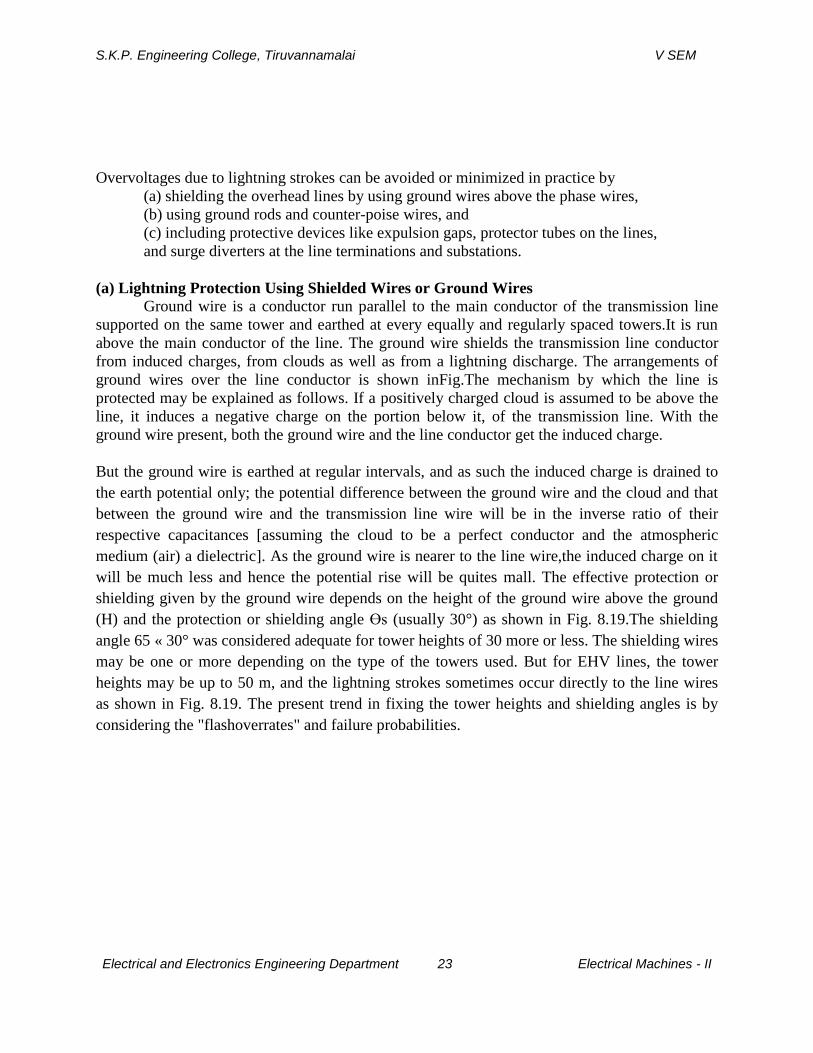
will be much less and hence the potential rise will be quites mall. The effective protection or
shielding given by the ground wire depends on the height of the ground wire above the ground
(H) and the protection or shielding angle Өs (usually 30°) as shown in Fig. 8.19.The shielding
angle 65 « 30° was considered adequate for tower heights of 30 more or less. The shielding wires
may be one or more depending on the type of the towers used. But for EHV lines, the tower
heights may be up to 50 m, and the lightning strokes sometimes occur directly to the line wires
as shown in Fig. 8.19. The present trend in fixing the tower heights and shielding angles is by
considering the "flashoverrates" and failure probabilities.
S.K.P. Engineering College, Tiruvannamalai V SEM
Electrical and Electronics Engineering Department 24 Electrical Machines - II
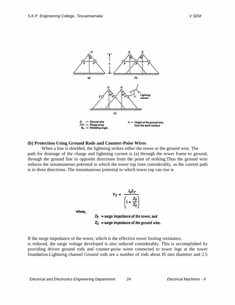
(b) Protection Using Ground Rods and Counter-Poise Wires
When a line is shielded, the lightning strikes either the tower or the ground wire. The
path for drainage of the charge and lightning current is (a) through the tower frame to ground,
through the ground line in opposite directions from the point of striking.Thus the ground wire
reduces the instantaneous potential to which the tower top rises considerably, as the current path
is in three directions. The instantaneous potential to which tower top can rise is
If the surge impedance of the tower, which is the effective tower footing resistance,
is reduced, the surge voltage developed is also reduced considerably. This is accomplished by
providing driven ground rods and counter-poise wires connected to tower legs at the tower
foundation.Lightning channel Ground rods are a number of rods about IS mm diameter and 2.5
S.K.P. Engineering College, Tiruvannamalai V SEM
Electrical and Electronics Engineering Department 25 Electrical Machines - II
to 3 m long driveninto the ground. In hard soils the rods may be much longer and can be driven
to a depthof, say, 50 m. They are usually made of galvanized iron or copper bearing steel. The
spacings of the rods, the number of rods, and the depth to which they are driven depend on the
desired tower footing resistance. With 10 rods of 4 m long and spaced5 m apart, connected to the
legs of the tower, the dynamic or effective resistance maybe reduced to 10 ft.The above effect is
alternatively achieved by using counter-poise wires. Counter-poise wires are wires buried in the
ground at a depth of 0.5 to 1.0 m, running parallel to the transmission line conductors and
connected to the tower legs/These wires maybe 50 to 100 m long.'These are found to be more
effective than driven rods and thesurge impedance of the tower may be reduced to as low as 25
£1. The depth does not materially affect the resistance of the counter-poise, and it is only
necessary to bury it to a depth enough to prevent theft. It is desirable to use a larger number of
parallel wires than a single wire. But it is difficult to lay counter-poise wires compared to ground
or driven rods.
(c) Protective Devices
In regions where lightning strokes are intensive or heavy, the overhead lines within these
zones are fitted with shunt protected devices. On the line itself two devices known as expulsion
gaps and protector tubes are used. Line terminations, junctions of lines, and sub-stations are
usually fitted with surge diverters.
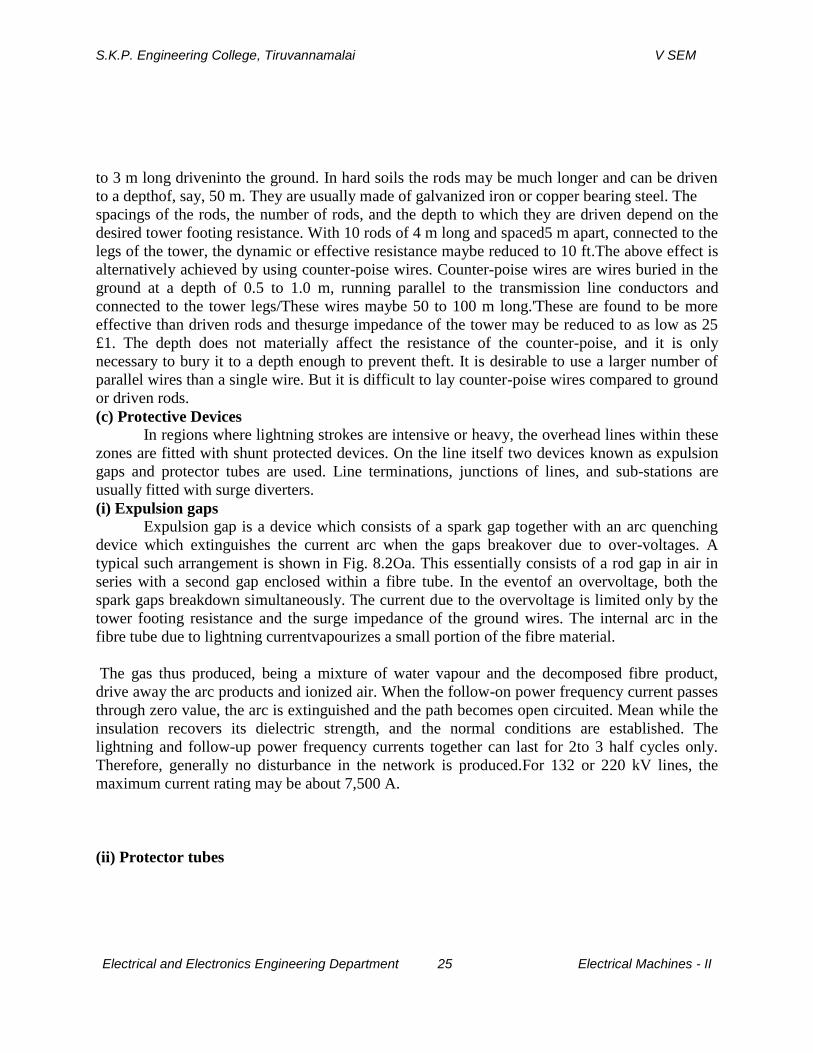
(i) Expulsion gaps
Expulsion gap is a device which consists of a spark gap together with an arc quenching
device which extinguishes the current arc when the gaps breakover due to over-voltages. A
typical such arrangement is shown in Fig. 8.2Oa. This essentially consists of a rod gap in air in
series with a second gap enclosed within a fibre tube. In the eventof an overvoltage, both the
spark gaps breakdown simultaneously. The current due to the overvoltage is limited only by the
tower footing resistance and the surge impedance of the ground wires. The internal arc in the
fibre tube due to lightning currentvapourizes a small portion of the fibre material.
The gas thus produced, being a mixture of water vapour and the decomposed fibre product,
drive away the arc products and ionized air. When the follow-on power frequency current passes
through zero value, the arc is extinguished and the path becomes open circuited. Mean while the
insulation recovers its dielectric strength, and the normal conditions are established. The
lightning and follow-up power frequency currents together can last for 2to 3 half cycles only.
Therefore, generally no disturbance in the network is produced.For 132 or 220 kV lines, the
maximum current rating may be about 7,500 A.
(ii) Protector tubes
S.K.P. Engineering College, Tiruvannamalai V SEM
Electrical and Electronics Engineering Department 26 Electrical Machines - II
A protector tube is similar to the expulsion gap in, construction and principle. It also
consists of a rod or spark gap in air formed by the line conductor and its high voltage terminal. It
is mounted underneath the line conductor on a tower. The arrangement is shown in Fig. . The
hollow gap in the expulsion tube is replaced by a nonlinear element which offers a very high
impedance at low currents but has low impedance for high or lightning currents. When an
overvoltage occurs and the spark gap breaks
down, the current is limited both by its own resistance and the tower footing resistance. The
overvoltage on the line is reduced to the voltage drop across the protector tube. After the surge
current is diverted and discharged to the ground, the follow-on normal power frequency current
will be limited by its high resistance. After the current zero of power frequency, the spark gap
recovers the insulation strength quickly. Usually, the flashover voltage of the protector tube is
less than that of the line insulation, and hence it can discharge the lightning overvoltage
effectively.
(iii) Rod gaps
A much simpler and effective protective device is a rod-gap However, it does not meet
the complete requirement. The sparkover voltage of a rod gap depends on the atmospheric
conditions. A typicalvolt-time characteristic of a 67 cm-rod gap is shown in Fig. with its
protective margin. There is no current limiting device provided so as to limit the current after
S.K.P. Engineering College, Tiruvannamalai V SEM
Electrical and Electronics Engineering Department 27 Electrical Machines - II
sparkover, and hence a series resistance is often used. Without a series resistance, the sparking
current may be very high and the applied impulse voltage suddenly collapses to zero thus
creating a steep step voltage, which sometimes proves to be very dangerous to the apparatus to
be protected, such as transformer or the machine windings. Nevertheless, rod gaps do provide
efficient protection where thunderstorm activity is less and the lines are protected by ground
wires.
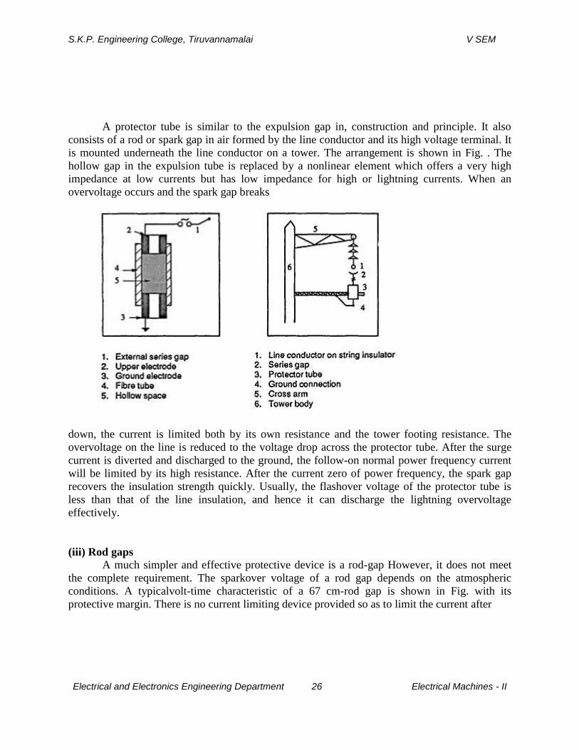
(iv) Surge diverters or lightning arresters
Surge diverters or lightning arresters are devices used at sub-stations and at line
terminations to discharge the lightning overvoltages and short duration switching surges. These
are usually mounted at the line end at the nearest point to the sub-station. They have a flashover
voltage power than that of any other insulation or apparatus at the sub-station. These are capable
of discharging 10 to 20 kA of long duration surges (8/20 p. s) and 100 to 250 kA of the short
duration surge currents (1/5\JL s)
Surge Diverters
These are non-linear resistors in series with spark gaps which act as fast switches.
Atypical surge diverter or lightning arrester is shown in Fig. and its characteristics are given in
Fig. A number of non-linear resistor elements made of silicon carbide are stacked one over the
other into two or three sections. They are usually separated by spark gaps (see Fig.).
The entire assembly is housed in a porcelain water-tight housing. When a surge voltage is
applied to the surge diverter, it breaksdown giving the discharge current I and maintains a
S.K.P. Engineering College, Tiruvannamalai V SEM
Electrical and Electronics Engineering Department 28 Electrical Machines - II
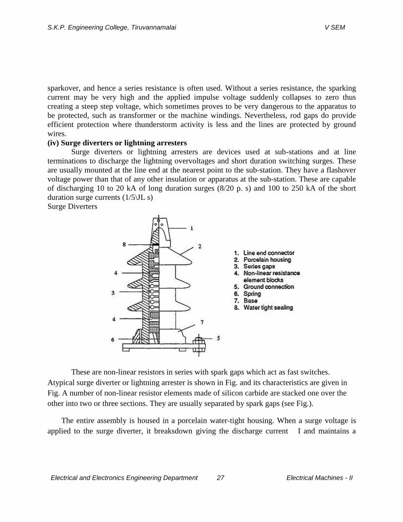
voltage V across it Thus, it provides a protection to the apparatus to be protected above the
protective level Vp(see Fig.).The lighter designs operate for smaller duration of currents, while
the heavy duty surge diverters with assisted or active gaps are designed for high currents and
long duration surges.
The lighter design arresters can interrupt 100 to 300 A of power frequency follow-on
current and about 5000 A of surge currents. If the current is tobe more and has to be exceeded,
the number of series elements has to be increased or some other method to limit the current has
to be used. In heavy duty arresters, the gaps are so arranged that the arc burns in the magnetic
field of the coils excited by power frequency follow-on currents. During lightning discharges, a
high voltage is induced in the coil by the steep front of the surge, and sparking occurs in an
auxiliary gap. For power frequency follow-on currents, the auxiliary gap is extinguished, as
sufficient voltage will not be present across the auxiliary gap to maintain an arc.
The main gap arcs occur in the magnetic field of the coils. The magnetic field, aided by
the born shaped main gap electrodes, elongates the arc and quenches it rapidly. The follow-on
current is limited by the voltage drop across the arc and the resistance element. During surge
discharge the lightning protective level becomes low.Sometimes, it is possible to limit the power
frequency and other overvoltages after a certain number of cycles using surge diverters. The
permissible voltage and duration depend on the thermal capacity of the diverter. The rated
diverter voltage is normally chosen so that it is not less than the power frequency overvoltage
expected (line to ground) at the point of installation, under any faulty or abnormal operating
condition.
S.K.P. Engineering College, Tiruvannamalai V SEM
Electrical and Electronics Engineering Department 29 Electrical Machines - II
8.Explain corona and its effect on power system. (CO1-L1-JUNE2014)
Corona, also known as partial discharge, is a type of localized emission resulting from
transient gaseous ionization in an insulation system when the voltage stress, i.e., voltage
gradient, exceeds a critical value. The ionization is usually localized over only a portion of the
distance between the electrodes of the system. Corona can occur within voids in insulators as
well as at the conductor/insulator interface.
Corona Inception
Corona inception voltage is the lowest voltage at which continuous corona of specified
pulse amplitude occurs as the applied voltage is gradually increased. Corona inception voltage
decreases as the frequency of the applied voltage increases. Corona can occur in applications as
low as 300V.
Corona Extinction
Corona extinction voltage is the highest voltage at which continuous corona of specified
pulse amplitude no longer occurs as the applied voltage is gradually decreased from above the
corona inception value. Thus, once corona starts, the voltage must be decreased to get it to stop.
Corona Detection
Corona can be visible in the form of light, typically a purple glow, as corona
generallyconsists of micro arcs. Darkening the environment can help to visualize the corona.
We once attached a camera (set to a long exposure time) to a viewing window in a vacuum
chamber to confirm that corona was indeed occurring, and thereby confirming our suspicions.
you can often hear corona hissing or cracking. Thus, stethoscopes or ultrasonic detectors
(assuming you can place them in a safe location) can be used to find corona. In addition, you
can sometimes smell the presence of ozone that was produced by the corona.
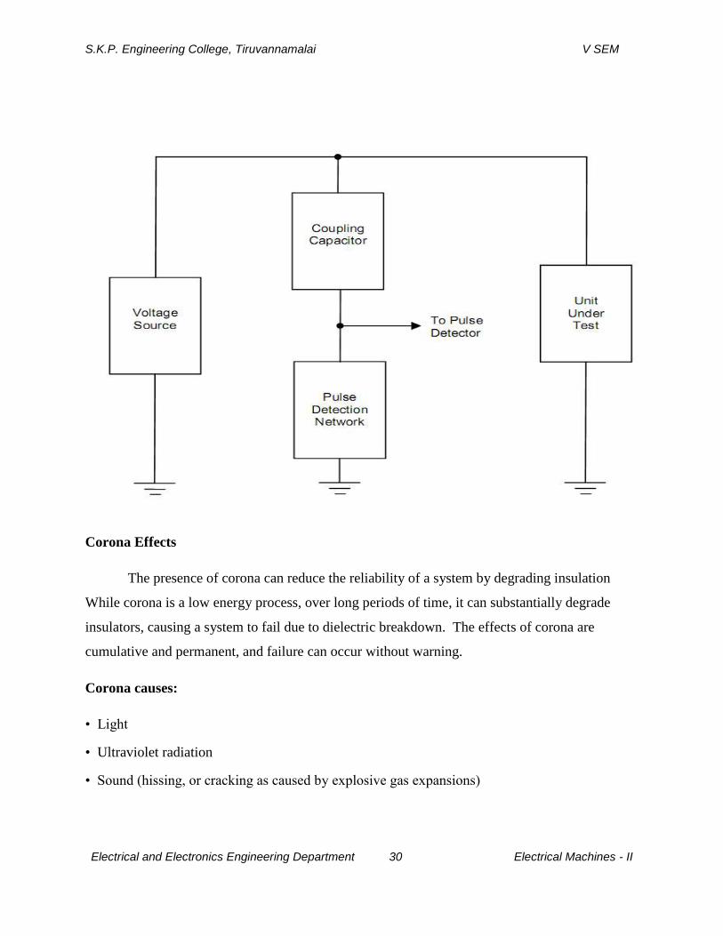
corona discharges in insulation systems result in voltage transients. These pulses are
superimposed on the applied voltage and may be detected, which is precisely what corona
detection equipment looks for. In its most basic form, the following diagram is a corona
(or partial discharge) measuring system:
S.K.P. Engineering College, Tiruvannamalai V SEM
Electrical and Electronics Engineering Department 30 Electrical Machines - II
Corona Effects
The presence of corona can reduce the reliability of a system by degrading insulation
While corona is a low energy process, over long periods of time, it can substantially degrade
insulators, causing a system to fail due to dielectric breakdown. The effects of corona are
cumulative and permanent, and failure can occur without warning.
Corona causes:
• Light
• Ultraviolet radiation
• Sound (hissing, or cracking as caused by explosive gas expansions)
S.K.P. Engineering College, Tiruvannamalai V SEM
Electrical and Electronics Engineering Department 31 Electrical Machines - II
• Ozone
• Nitric and various other acids
• Salts, sometimes seen as white powder deposits
• Other chemicals, depending on the insulator material
• Mechanical erosion of surfaces by ion bombardment
• Heat (although generally very little, and primarily in the insulator)
• Carbon deposits, thereby creating a path for severe arcing
Corona Prevention
Corona can be avoided by minimizing the voltage stress and electric field gradient. This is
complished by using utilizing good high voltage design practices, i.e., maximizing the distance
between conductors that have large voltage differentials, using conductors with Page 4large radii,
and avoiding parts that have sharp points or sharp edges. Corona inception voltage can
sometimes be increased by using a surface treatment, such as a semiconductor layer, high voltage
putty or corona dope. Also, use a good, homogeneous insulator. Void free solids, such as
properly prepared silicone and epoxy potting materials work well. If you are limited to using air
as your insulator, then you are left with geometry as the critical parameter. Finally, ensure that
steps are taken to reduce or eliminate unwanted voltage transients, which can cause corona to
start.
UNIT II
S.K.P. Engineering College, Tiruvannamalai V SEM
Electrical and Electronics Engineering Department 32 Electrical Machines - II
DIELECTRIC BREAKDOWN
PART A
1.Define Gas Law. (CO2-L1-NOV2014)
It consists of many laws. The following laws are very important.
a) Charle’s law P α T Volume is constant
b) Boyle’s law P α 1/V T is constant
General equation: PV = nRT
Where
P-pressure ; V-Volume; n-number of moles; R-molar gas constant; T-temperature.
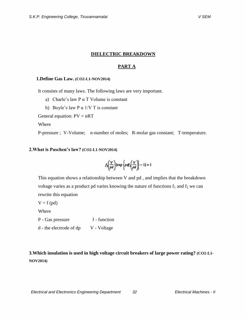
2.What is Paschen’s law? (CO2-L1-NOV2014)
This equation shows a relationship between V and pd , and implies that the breakdown
voltage varies as a product pd varies knowing the nature of functions f1 and f2 we can
rewrite this equation
V = f (pd)
Where
P - Gas pressure f - function
d - the electrode of dp V - Voltage
3.Which insulation is used in high voltage circuit breakers of large power rating? (CO2-L1-
NOV2014)
S.K.P. Engineering College, Tiruvannamalai V SEM
Electrical and Electronics Engineering Department 33 Electrical Machines - II
Now a day’s most of all circuit breakers that are in operation use SF6 gas or vacuum as
insulating medium. SF6 circuit breakers are manufactured up to the higher transmission
voltage of 800 kV and current range of 63 kA and 80 kA. However it is an expensive gas
and at the normal operating pressure of 6 bar it condenses at temperatures lower than
20°C.
4.What is Time lag in the breakdown of dielectrics? (CO2-L1-NOV2014)
The time that elapses between the application of the voltage to a gap sufficient to cause
breakdown and actual breakdown is called time lag.
5.Define uniform and non uniform field and give examples of each. (CO2-L1-NOV2014)
In uniform field the applied field remains constant across the gap. Example: The field
between the two plane electrodes.
In non uniform field the applied field varies across the gap.
The examples are coaxial cylinders, point- plane and the sphere plane gaps.
6.Define the following as applied to high voltage breakdown. (CO2-L1-NOV2014)
a) Internal and External insulation
b) Flashover
a) Internal and External insulation
Disruptive discharge voltage produces the loss of dielectric strength of insulation. It is
the voltage at which the electrical stress in the insulation causes a failure which
includes the collapse of voltage and passage of current.
b) Flashover
When discharge takes place between two electrodes in gas or liquid over a solid
surface on air it is called flashover.

S.K.P. Engineering College, Tiruvannamalai V SEM
Electrical and Electronics Engineering Department 34 Electrical Machines - II
7.Define the following as applied to disruptive voltage. (CO2-L1-NOV2014)
a) Flashover voltage
b) Spark over voltage
a) Flashover
When discharge takes place between two electrodes in gas or liquid over a solid
surface on air it is called flashover.
b) Spark over voltage
The voltage between two spheres on sphere gap is raised till a spark passes
between two spheres. The value voltage of spark over depends upon the dielectric
strength of air, size of sphere and distance between the sphere and other factors.
8.Name a few gases used as insulation medium? (CO2-L1-NOV2014)
N2, CO2, CC2F2 (Freon), SF6 (SulphurHexa Fluoride)
9.Name the theories explaining B.D in gaseous insulation? (CO2-L1-NOV2014)
1) Town sends Theory
2) Streamer Theory.
10.What are the physical conditions governing ionization mechanism in gases dieletrics?
(CO2-L1-NOV2014)
1.Pressure 2.Temperature 3.Electrode configuration
S.K.P. Engineering College, Tiruvannamalai V SEM
Electrical and Electronics Engineering Department 35 Electrical Machines - II
4.Nature of electrode surface 5.Availability of initial conducti g particles
11.What is primary ionization? (CO2-L1-NOV2014)
Electron produced at the cathode by some external means, during its travel towards
the anode due to the field applied, make collisions with neutral atoms/molecules and
liberate electrons & positive ions The liberated ions make future collisions and the process
continue. The electrons and the ions constitute current. This process is called primary
ionization.
12.What is secondary ionization? (CO2-L1-NOV2014)
The librated positive ions, during the primary ionization process migrate wards cathode bombard and emit secondary electrons from the cathode. The excited atoms/molecules, got excited during the collision of initial electrons, emit photons which bombard the cathode & emit secondary electrons Metastable (excited particles) bombard the cathode metal surface & produceSecondary Electrons
13.Define primary ionization co-efficient .(Town-sends Ist ionization co-efficient)? (CO2-L1-
NOV2014)
The average number of ionizing collisions made by an electron per centimeter travel
of the electron in the direction of the field is called Town-sends Ist ionization co-efficient
.It depends on the gas pressure and E/P
14.What is meant by Townsend discharge and explain its main feature? (CO2-L1-NOV2014)
When the voltage between anode and cathode is increased the current in the anode
equals the current in the external circuit. Therefore the current becomes infinitely large
under the above mentioned condition but practically it is limited by the resistance of
external circuit and practically by the voltage drop in the arc. The condition Veαc
= 1
defines the condition for the beginning of spark and is known Townsend criterion for
spark formation or breakdown.
S.K.P. Engineering College, Tiruvannamalai V SEM
Electrical and Electronics Engineering Department 36 Electrical Machines - II
15.What are the different theories related with liquid dielectric breakdown? (CO2-L1-
NOV2014)
The first theory is extension of gaseous breakdown based on the avalanche ionization of
atoms caused electron collision in the applied field. The second theory is based on the
fact the presence of foreign particles in liquid insulation is polarizable and is of higher
permittivity than the liquid.
16.Distinguish between insulators and dielectrics and give examples for each. (CO2-L2-
NOV2014)
A dielectric is a non conducting substance ie, an insulator. Although the dielectric and
insulator are generally considered synonymous the term dielectric is more often used to
describe the material where the dielectric polarization is important like the insulating
material between the metallic plates of a capacitor while insulator is more often used
when the material is being used to prevent a current flow across it.
Examples of insulators: Glass and porcelain
Examples of dielectric: Paper and Mica
17.What are Meta stable atoms? How they are ionizing the gaseous dielectric medium?
A Meta stable atom or a molecule is an excited particle whose life time is very large (10-3
sec) compared to the life time of an ordinary particle. Meta stables have a relatively high
potential energy and are therefore able to ionize neutral particles.
18.What is composite dielectric? (CO2-L1-NOV2014)
It is difficult to imagine complete insulation system in electrical equipment which does
not consist of more than one type of insulation. If insulation as a whole is considered, it
will be found that more than one insulating material is used. These different materials can
be in parallel with each other such as air or SF6 in parallel with solid insulation or in
series with one another. Such insulation systems are called composite dielectrics.
S.K.P. Engineering College, Tiruvannamalai V SEM
Electrical and Electronics Engineering Department 37 Electrical Machines - II
19.Define formative time lag. (CO2-L1-NOV2014)
After the appearance of the electron a time tf is required for the ionization processes to
develop fully to cause the breakdown of the gap and this time is called formative time
lag.
20.Define penning effect. (CO2-L1-NOV2014)
A small percentage of Argon in Neon reduces substantially the dielectric strength of
pure Neon. In fact, the dielectric strength is smaller than the dielectric strengths of either
pure Neon or Argon. The lowering of dielectric strength is due to the fact that the lowest
excited stage of neon is metastable and its excitation potential (16 ev) is about 0.9 ev
greater than the ionization potential of Argon. The metastable atoms have a long life in
neon gas, and on hitting Argon atoms there is a very high probability of ionizing them.
This phenomenon is known as Penning Effect.
PART B
S.K.P. Engineering College, Tiruvannamalai V SEM
Electrical and Electronics Engineering Department 38 Electrical Machines - II
1.Deduce an expression for townsend’scrireria for breakdown of gaseous medium. (CO2-L1-
NOV2014)
GASES AS INSULATING MEDIA
The simplest and the most commonly found dielectrics are gases. Most of the electrical
apparatus use air as the insulating medium, and in a few cases other gases such as nitrogen (N2,
carbon dioxide (CO2, freon (CCL2F2) and sulphur hexafluoride (SF6) are also used. Various
phenomena occur in gaseous dielectrics when a voltage is applied. When the applied voltage is
low, small currents flow between the electrodes and the insulation retains its electrical properties.
On the other hand, if the applied voltages are large, the current flowing through the insulation
increases very sharply, and an electrical breakdown occurs. A strongly conducting spark formed
during breakdown practically produces a short circuit between the electrodes. The maximum
voltage applied to the insulation at the moment of breakdown is called the breakdown voltage. In
order to understand the breakdown phenomenon in gases, a study of the electrical properties of
gases and the processes by which high currents are produced in gases is essential. The electrical
discharges in gases are of two types, i.e. (i) non-sustaining discharges, and (ii) self-sustaining
types. The breakdown in a gas, called spark breakdown is the transition of a non-sustaining
discharge into a self-sustaining discharge. The build-up of high currents in a breakdown is due to
the process known as ionization in which electrons and ions are created from neutral atoms or
molecules, and their migration to the anode and cathode respectively leads to high currents. At
present two types of theories, viz. (i) Townsend theory, and (ii) Streamer theory are known
which explain the mechanism for breakdown under different conditions. The various physical
conditions of gases, namely, pressure, temperature, electrode field configuration, nature of
electrode surfaces, and the availability of initial conducting particles are known to govern the
ionization processes
TOWNSENDS FIRST IONIZATION PROCESSES
A gas in its normal state is almost a perfect insulator. However, when a high voltage is
applied between the two electrodes immersed in a gaseous medium, the gas becomes a conductor
and an electrical breakdown occurs. A gas in its normal state is almost a perfect insulator.
However, when a high voltage is applied between the two electrodes immersed in a gaseous
medium, the gas becomes a conductor and an electrical breakdown occurs. The processes that are
primarily responsible for the breakdown of a gas are ionization by collision, photo-ionization,
S.K.P. Engineering College, Tiruvannamalai V SEM
Electrical and Electronics Engineering Department 39 Electrical Machines - II
and the secondary ionization processes. In insulating gases (also called electron-attaching gases)
the process of attachment also plays an important role.
Ionization by Collision
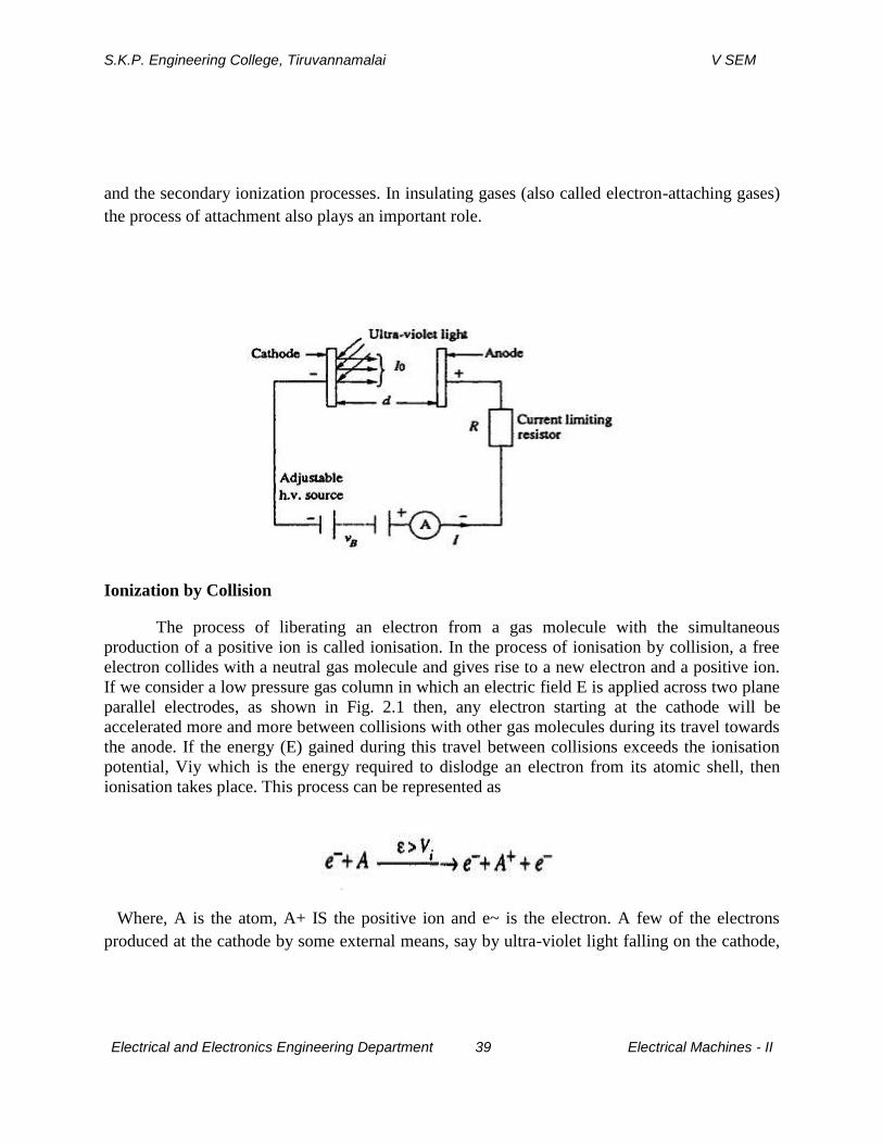
The process of liberating an electron from a gas molecule with the simultaneous
production of a positive ion is called ionisation. In the process of ionisation by collision, a free
electron collides with a neutral gas molecule and gives rise to a new electron and a positive ion.
If we consider a low pressure gas column in which an electric field E is applied across two plane
parallel electrodes, as shown in Fig. 2.1 then, any electron starting at the cathode will be
accelerated more and more between collisions with other gas molecules during its travel towards
the anode. If the energy (E) gained during this travel between collisions exceeds the ionisation
potential, Viy which is the energy required to dislodge an electron from its atomic shell, then
ionisation takes place. This process can be represented as
Where, A is the atom, A+ IS the positive ion and e~ is the electron. A few of the electrons
produced at the cathode by some external means, say by ultra-violet light falling on the cathode,
S.K.P. Engineering College, Tiruvannamalai V SEM
Electrical and Electronics Engineering Department 40 Electrical Machines - II
ionise neutral gas particles producing positive ions and additional electrons. The additional
electrons, then, themselves make 'ionising collisions' and thus the process repeats itself. This
represents an increase in the electron current, since the number of electrons reaching the anode
per unit time is greater than those liberated at the cathode. In addition, the positive ions also
reach the cathode and on bombardment on the cathode give rise to secondary electrons.
TOWNSEND’S FIRST IONIZATION COEFFICIENT
Consider a parallel plate capacitor having gas as an insulating medium and separated by a
distance d as shown in Fig.1.1. When no electric field is set up between the plates, a state of
equilibrium exists between the state of electron and positive ion generation due to the decay
processes. This state of equilibrium will be disturbed moment a high electric field is applied.
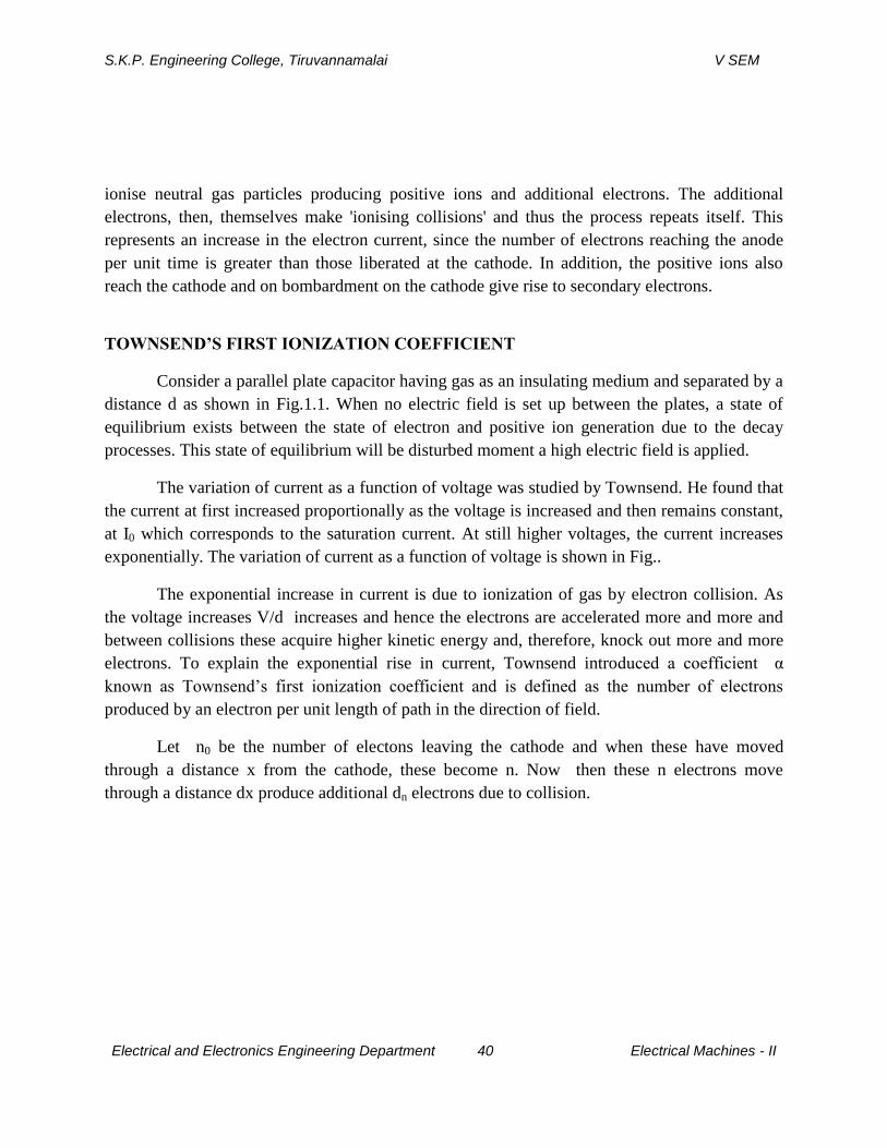
The variation of current as a function of voltage was studied by Townsend. He found that
the current at first increased proportionally as the voltage is increased and then remains constant,
at I0 which corresponds to the saturation current. At still higher voltages, the current increases
exponentially. The variation of current as a function of voltage is shown in Fig..
The exponential increase in current is due to ionization of gas by electron collision. As
the voltage increases V/d increases and hence the electrons are accelerated more and more and
between collisions these acquire higher kinetic energy and, therefore, knock out more and more
electrons. To explain the exponential rise in current, Townsend introduced a coefficient α
known as Townsend’s first ionization coefficient and is defined as the number of electrons
produced by an electron per unit length of path in the direction of field.
Let n0 be the number of electons leaving the cathode and when these have moved
through a distance x from the cathode, these become n. Now then these n electrons move
through a distance dx produce additional dn electrons due to collision.

S.K.P. Engineering College, Tiruvannamalai V SEM
Electrical and Electronics Engineering Department 41 Electrical Machines - II
The term eαd
is called the electron avalanche and it represents the number of electrons
produced by one electron in travelling from cathode to anode.
S.K.P. Engineering College, Tiruvannamalai V SEM
Electrical and Electronics Engineering Department 42 Electrical Machines - II
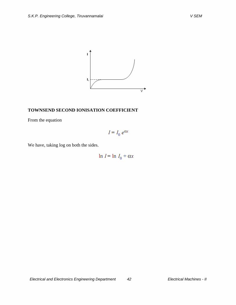
TOWNSEND SECOND IONISATION COEFFICIENT
From the equation
We have, taking log on both the sides.

S.K.P. Engineering College, Tiruvannamalai V SEM
Electrical and Electronics Engineering Department 43 Electrical Machines - II
This is a straight line equation with slope α and intercept lnI0 as shown in Fig. if for a
given pressure p, E is kept constant. Townsend in his earlier investigations had observed that the
current in parallel plate gap increased more rapidly with increase in voltage as compared to the
one given by the above equation.
To explain this departure from linearity, Townsend suggested that a second mechanism
must be affecting the current. He postulated that the additional current must be due to the
presence of positive ions and the photons. The positive ions will liberate electrons by collision
with gas molecules and by bombardment against the cathode. Similarly, the photons will also
release electrons after collision with gas molecules and from the cathode after photon impact. Let
us consider the phenomenon of self-sustained discharge where the electrons are released from
the cathode by positive ion bombardment.
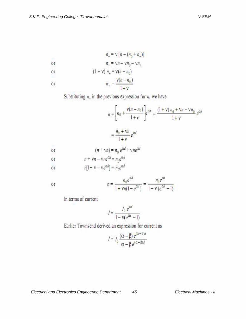
Let n0 be the number of electrons released from the cathode by ultraviolet radiation, n+
the number of electrons released from the cathode due to positive ion bombardment and n the
number of electrons reaching the anode.
S.K.P. Engineering College, Tiruvannamalai V SEM
Electrical and Electronics Engineering Department 44 Electrical Machines - II
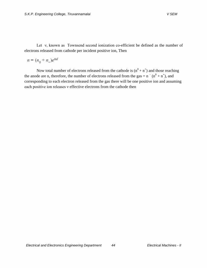
Let ν, known as Townsend second ionization co-efficient be defined as the number of
electrons released from cathode per incident positive ion, Then
Now total number of electrons released from the cathode is (n0
+ n+) and those reaching
the anode are n, therefore, the number of electrons released from the gas = n – (n
0 + n
+), and
corresponding to each electron released from the gas there will be one positive ion and assuming
each positive ion releases ν effective electrons from the cathode then
S.K.P. Engineering College, Tiruvannamalai V SEM
Electrical and Electronics Engineering Department 45 Electrical Machines - II
S.K.P. Engineering College, Tiruvannamalai V SEM
Electrical and Electronics Engineering Department 46 Electrical Machines - II
where β represents the number of ion pairs produced by positive ion travelling 1 cm path in the
direction of field.
Townsend’s original suggestion that the positive ion after collision with gas molecule
releases electron does not hold good as ions rapidly lose energy in elastic collision and ordinarily
are unable to gain sufficient energy from the electric field to cause ionization on collision with
gas molecules or atoms.In practice positive ions, photons and metastable, all the three may
participate in the process of ionization. It depends upon the experimental conditions. There may
be more than one mechanism producing secondary ionization in the discharge gap and, therefore,
it is customary to express the net secondary ionization effect by a single coefficient v and
represent the current by the above equation keeping in mind that ν may represent one or more of
the several possible mechanism.
It is to be noted that the value of ν depends upon the work function of the material. If the
work function of the cathode surface is low, under the same experimental conditions will
produce more emission. Also, the value of ν is relatively small at low value of E/p and will
increase with increase in E/p. This is because at higher values of E/p, there will be more number
of positive ions and photons of sufficiently large energy to cause ionization upon impact on the
cathode surface. It is to be noted that the influence of ν on breakdown mechanism is restricted to
Townsend breakdown mechanism i.e., to low-pressure breakdown only.
2.Explain streamer breakdown. (CO2-L1-MAY2013)
STREAMER OR KANAL MECHANISM OF SPARK
We know that the charges in between the electrodes separated by a distance d increase
by a factor eαd
when field between electrodes is uniform. This is valid only if we assume that the
field E0 = V/d is not affected by the space charges of electrons and positive ions. Reather has
observed that if the charge concentration is higher than 106 but lower than 108 the growth of an
avalanche is weakened i.e., dn/dx < eαd
. Whenever the concentration exceeds 108, the
S.K.P. Engineering College, Tiruvannamalai V SEM
Electrical and Electronics Engineering Department 47 Electrical Machines - II
avalanche current is followed by steep rise in current and breakdown of the gap takes place. The
weakening of the avalanche at lower concentration and rapid growth of avalanche at higher
concentration have been attributed to the modification of the Fig. Field redistribution due to
space charge electric field E0 due to the space charge field. Fig.shows the electric field around
an avalanche as it progresses along the gap and the resultant field i.e., the superposition of the
space charge field and the original field E0.
Since the electrons have higher mobility, the space charge at the head of the avalanche is
considered to be negative and is assumed to be concentrated within a spherical volume.It can be
seen from Fig. 1.4 that the filed at the head of the avalanche is strengthened. The field between
the two assumed charge centres i.e., the electrons and positive ions is decreased as the field due
to the charge centres opposes the main field E0 and again the field between the positive space
charge centre and the cathode is strengthened as the space charge field aids the main field E0 in
this region. It has been observed that if the charge carrier number exceeds 106, the field
distortion becomes noticeable. If the distortion of field is of 1%, it would lead to a doubling of
the avalanche but as the field distortion is only near the head of the avalanche, it does not have a
significance on the discharge phenomenon. However, if the charge carrier exceeds 108, the space
charge field becomes almost of the same magnitude as the main field E0 and hence it may lead
to initiation of a streamer. The space charge field, therefore, plays a very important role in the
mechanism of electric discharge in a non-uniform gap.
Townsend suggested that the electric spark discharge is due to the ionization of gas
molecule by the electron impact and release of electrons from cathode due to positive ion
bombardment at the cathode. According to this theory, the formative time lag of the spark should
be at best equal to the electron transit time t. At pressures around atmospheric and above p.d. >
103Torr-cm, the experimentally determined time lags have been found to be much shorter than tr.
Study of the photographs of the avalanche development has also shown that under certain
conditions, the space charge developed in an avalanche is capable of transforming the avalanche
into channels of ionization known as streamers that lead to rapid development of breakdown. It
has also been observed through measurement that the transformation from avalanche to streamer
generally takes place when the charge within the avalanche head reaches a critical value of
where Xc is the length of the avalanche parth in field direction when it reaches the critical size.
If the gap length d <Xc, the initiation of streamer is unlikely.T he short-time lags associated with
the discharge development led Raether and independently Meek and Meek and Loeb to the
S.K.P. Engineering College, Tiruvannamalai V SEM
Electrical and Electronics Engineering Department 48 Electrical Machines - II
advancement of the theory of streamer of Kanal mechanism for spark formation, in which the
secondary mechanism results from photoionization of gas molecules and is independent of the
electrodes. Raether and Meek have proposed that when the avalanche in the gap reaches a certain
critical size the combined space charge field and externally applied field E0 lead to intense
ionization and excitation of the gas particles in front of the avalanche head. There is
recombination of electrons and positive ion resulting in generation of photons and these photons
in turn generate secondary electrons by the photoionization process.
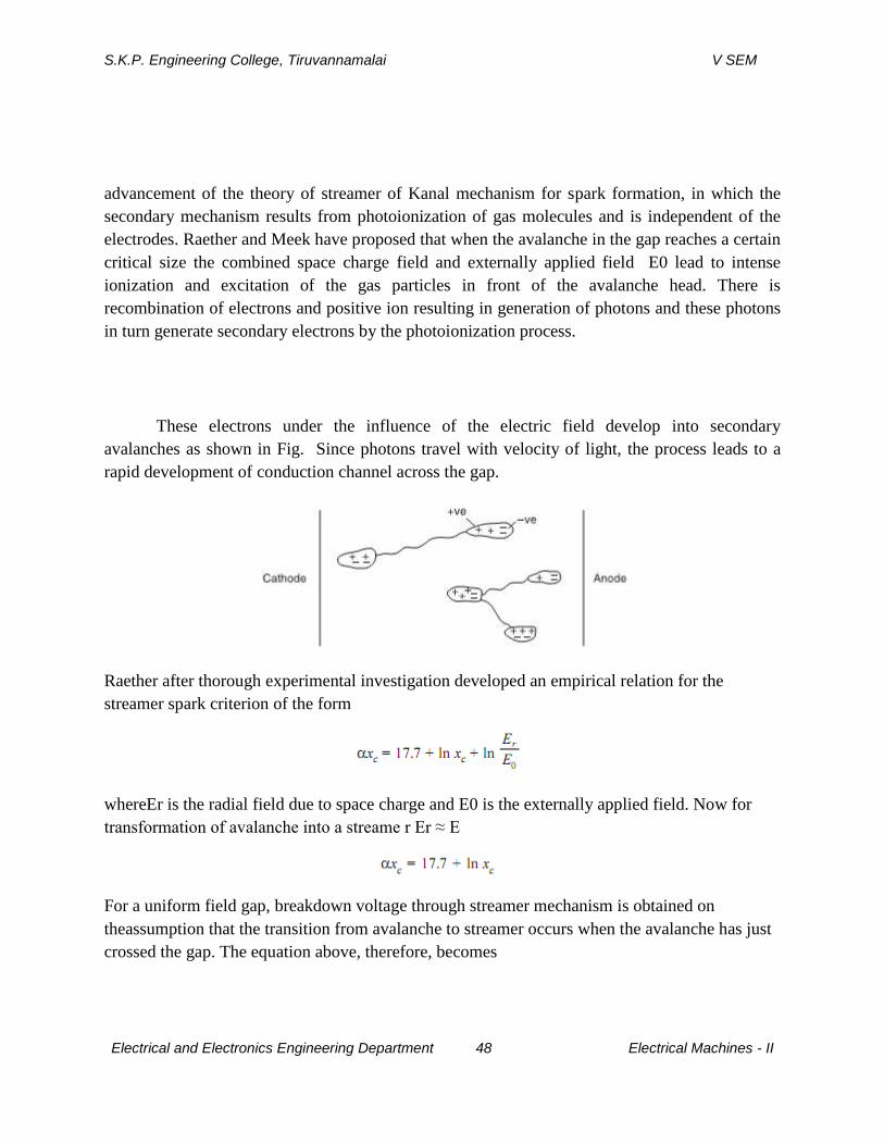
These electrons under the influence of the electric field develop into secondary
avalanches as shown in Fig. Since photons travel with velocity of light, the process leads to a
rapid development of conduction channel across the gap.
Raether after thorough experimental investigation developed an empirical relation for the
streamer spark criterion of the form
whereEr is the radial field due to space charge and E0 is the externally applied field. Now for
transformation of avalanche into a streame r Er ≈ E
For a uniform field gap, breakdown voltage through streamer mechanism is obtained on
theassumption that the transition from avalanche to streamer occurs when the avalanche has just
crossed the gap. The equation above, therefore, becomes
S.K.P. Engineering College, Tiruvannamalai V SEM
Electrical and Electronics Engineering Department 49 Electrical Machines - II
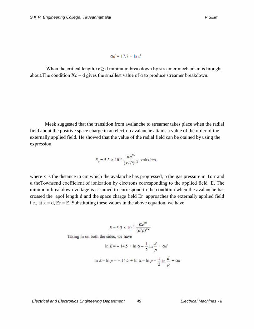
When the critical length xc ≥ d minimum breakdown by streamer mechanism is brought
about.The condition Xc = d gives the smallest value of α to produce streamer breakdown.
Meek suggested that the transition from avalanche to streamer takes place when the radial
field about the positive space charge in an electron avalanche attains a value of the order of the
externally applied field. He showed that the value of the radial field can be otained by using the
expression.
where x is the distance in cm which the avalanche has progressed, p the gas pressure in Torr and
α theTownsend coefficient of ionization by electrons corresponding to the applied field E. The
minimum breakdown voltage is assumed to correspond to the condition when the avalanche has
crossed the apof length d and the space charge field Er approaches the externally applied field
i.e., at x = d, Er = E. Substituting these values in the above equation, we have

S.K.P. Engineering College, Tiruvannamalai V SEM
Electrical and Electronics Engineering Department 50 Electrical Machines - II
The experimentally determined values of α/p and the corresponding E/p are used to solve the
above equation using trial and error method. Values of α/p corresponding to E/p at a given
pressure are chosen until the equation is satisfied.
3.State and explain paschen’s law. (CO2-L1-NOV2014)
THE SPARKING POTENTIAL—PASCHEN’S LAW
The Townsend’s Criterion
enables the evaluation of breakdown voltage of the gap by the use of appropriate values of α/p
and ν corresponding to the values E/p when the current is too low to damage the cathode and also
the space charge distortions are minimum. A close agreement between the calculated and
experimentally determined values is obtained when the gaps are short or long and the pressure is
relatively low. An expression for the breakdown voltage for uniform field gaps as a function of
gap length and gas pressure can be derived from the threshold equation by expressing the
ionization coefficient α/p as a function of field strength E and gas pressure p i.e.,
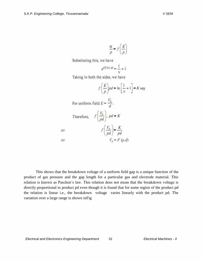
S.K.P. Engineering College, Tiruvannamalai V SEM
Electrical and Electronics Engineering Department 51 Electrical Machines - II
This shows that the breakdown voltage of a uniform field gap is a unique function of the
product of gas pressure and the gap length for a particular gas and electrode material. This
relation is known as Paschen’s law. This relation does not mean that the breakdown voltage is
directly proportional to product pd even though it is found that for some region of the product pd
the relation is linear i.e., the breakdown voltage varies linearly with the product pd. The
variation over a large range is shown inFig

S.K.P. Engineering College, Tiruvannamalai V SEM
Electrical and Electronics Engineering Department 52 Electrical Machines - II
4.Explain the phenomenon of corona discharges and breakdown mechanism in non
uniform field. (CO2-L1-NOV2014)
CORONA DISCHARGES
If the electric field is uniform and if the field is increased gradually, just when
measurable ionization begins, the ionization leads to complete breakdown of the gap. However,
in non-uniform fields, before the spark or breakdown of the medium takes place, there are many
manifestations in the form of visual and audible discharges. These discharges are known as
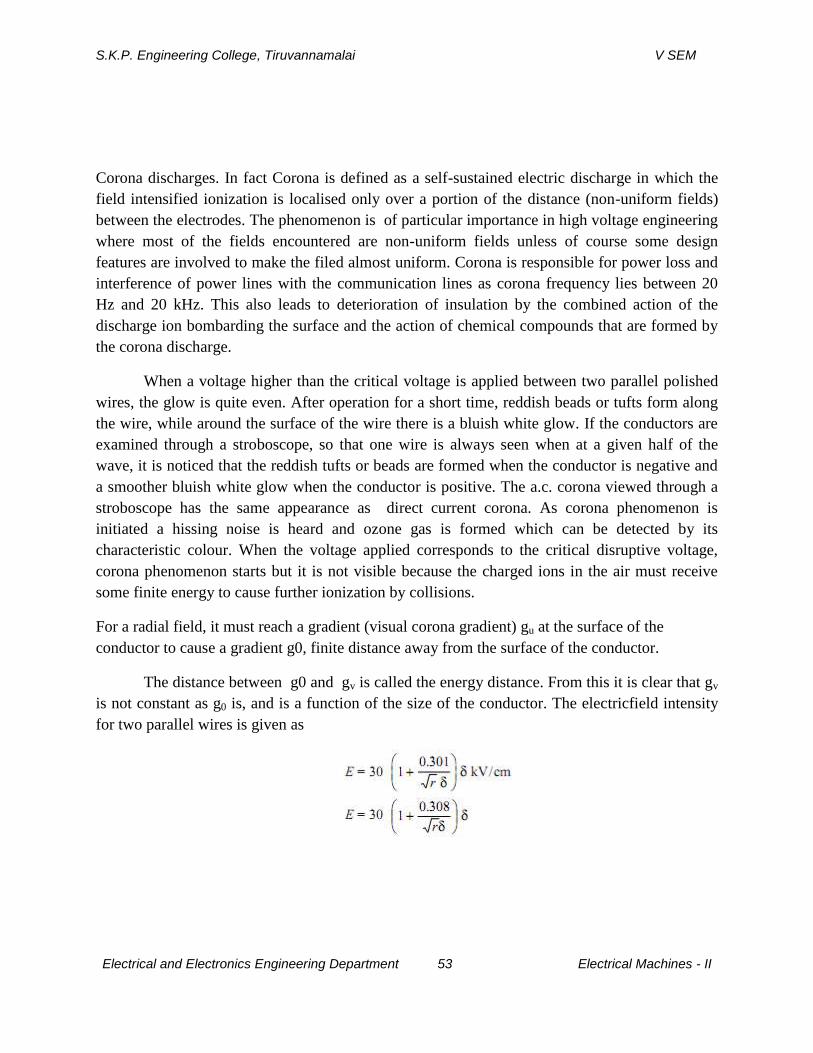
S.K.P. Engineering College, Tiruvannamalai V SEM
Electrical and Electronics Engineering Department 53 Electrical Machines - II
Corona discharges. In fact Corona is defined as a self-sustained electric discharge in which the
field intensified ionization is localised only over a portion of the distance (non-uniform fields)
between the electrodes. The phenomenon is of particular importance in high voltage engineering
where most of the fields encountered are non-uniform fields unless of course some design
features are involved to make the filed almost uniform. Corona is responsible for power loss and
interference of power lines with the communication lines as corona frequency lies between 20
Hz and 20 kHz. This also leads to deterioration of insulation by the combined action of the
discharge ion bombarding the surface and the action of chemical compounds that are formed by
the corona discharge.
When a voltage higher than the critical voltage is applied between two parallel polished
wires, the glow is quite even. After operation for a short time, reddish beads or tufts form along
the wire, while around the surface of the wire there is a bluish white glow. If the conductors are
examined through a stroboscope, so that one wire is always seen when at a given half of the
wave, it is noticed that the reddish tufts or beads are formed when the conductor is negative and
a smoother bluish white glow when the conductor is positive. The a.c. corona viewed through a
stroboscope has the same appearance as direct current corona. As corona phenomenon is
initiated a hissing noise is heard and ozone gas is formed which can be detected by its
characteristic colour. When the voltage applied corresponds to the critical disruptive voltage,
corona phenomenon starts but it is not visible because the charged ions in the air must receive
some finite energy to cause further ionization by collisions.
For a radial field, it must reach a gradient (visual corona gradient) gu at the surface of the
conductor to cause a gradient g0, finite distance away from the surface of the conductor.
The distance between g0 and gv is called the energy distance. From this it is clear that gv
is not constant as g0 is, and is a function of the size of the conductor. The electricfield intensity
for two parallel wires is given as
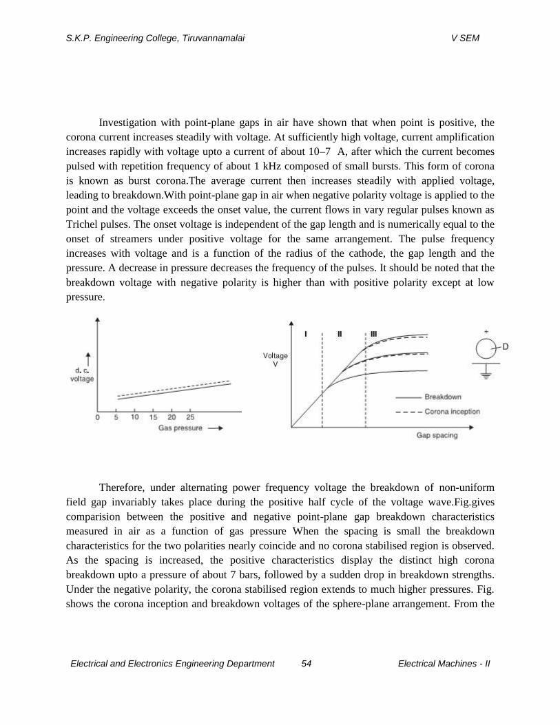
S.K.P. Engineering College, Tiruvannamalai V SEM
Electrical and Electronics Engineering Department 54 Electrical Machines - II
Investigation with point-plane gaps in air have shown that when point is positive, the
corona current increases steadily with voltage. At sufficiently high voltage, current amplification
increases rapidly with voltage upto a current of about 10–7 A, after which the current becomes
pulsed with repetition frequency of about 1 kHz composed of small bursts. This form of corona
is known as burst corona.The average current then increases steadily with applied voltage,
leading to breakdown.With point-plane gap in air when negative polarity voltage is applied to the
point and the voltage exceeds the onset value, the current flows in vary regular pulses known as
Trichel pulses. The onset voltage is independent of the gap length and is numerically equal to the
onset of streamers under positive voltage for the same arrangement. The pulse frequency
increases with voltage and is a function of the radius of the cathode, the gap length and the
pressure. A decrease in pressure decreases the frequency of the pulses. It should be noted that the
breakdown voltage with negative polarity is higher than with positive polarity except at low
pressure.
Therefore, under alternating power frequency voltage the breakdown of non-uniform
field gap invariably takes place during the positive half cycle of the voltage wave.Fig.gives
comparision between the positive and negative point-plane gap breakdown characteristics
measured in air as a function of gas pressure When the spacing is small the breakdown
characteristics for the two polarities nearly coincide and no corona stabilised region is observed.
As the spacing is increased, the positive characteristics display the distinct high corona
breakdown upto a pressure of about 7 bars, followed by a sudden drop in breakdown strengths.
Under the negative polarity, the corona stabilised region extends to much higher pressures. Fig.
shows the corona inception and breakdown voltages of the sphere-plane arrangement. From the
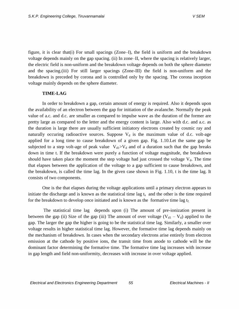
S.K.P. Engineering College, Tiruvannamalai V SEM
Electrical and Electronics Engineering Department 55 Electrical Machines - II
figure, it is clear that(i) For small spacings (Zone–I), the field is uniform and the breakdown
voltage depends mainly on the gap spacing. (ii) In zone–II, where the spacing is relatively larger,
the electric field is non-uniform and the breakdown voltage depends on both the sphere diameter
and the spacing.(iii) For still larger spacings (Zone-III) the field is non-uniform and the
breakdown is preceded by corona and is controlled only by the spacing. The corona inception
voltage mainly depends on the sphere diameter.
TIME-LAG
In order to breakdown a gap, certain amount of energy is required. Also it depends upon
the availability of an electron between the gap for initiation of the avalanche. Normally the peak
value of a.c. and d.c. are smaller as compared to impulse wave as the duration of the former are
pretty large as compared to the letter and the energy content is large. Also with d.c. and a.c. as
the duration is large there are usually sufficient initiatory electrons created by cosmic ray and
naturally occuring radioactive sources. Suppose Vd is the maximum value of d.c. volt-age
applied for a long time to cause breakdown of a given gap. Fig. 1.10.Let the same gap be
subjected to a step volt-age of peak value Vd1>Vd and of a duration such that the gap breaks
down in time t. If the breakdown were purely a function of voltage magnitude, the breakdown
should have taken place the moment the step voltage had just crossed the voltage Vd. The time
that elapses between the application of the voltage to a gap sufficient to cause breakdown, and
the breakdown, is called the time lag. In the given case shown in Fig. 1.10, t is the time lag. It
consists of two components.
One is the that elapses during the voltage applications until a primary electron appears to
initiate the discharge and is known as the statistical time lag ts and the other is the time required
for the breakdown to develop once initiated and is known as the formative time lag tf.
The statistical time lag depends upon (i) The amount of pre-ionization present in
between the gap (ii) Size of the gap (iii) The amount of over voltage (Vd1 – Vd) applied to the
gap. The larger the gap the higher is going to be the statistical time lag. Similarly, a smaller over
voltage results in higher statistical time lag. However, the formative time lag depends mainly on
the mechanism of breakdown. In cases when the secondary electrons arise entirely from electron
emission at the cathode by positive ions, the transit time from anode to cathode will be the
dominant factor determining the formative time. The formative time lag increases with increase
in gap length and field non-uniformity, decreases with increase in over voltage applied.
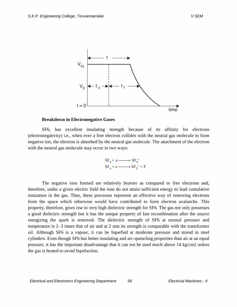
S.K.P. Engineering College, Tiruvannamalai V SEM
Electrical and Electronics Engineering Department 56 Electrical Machines - II
Breakdown in Electronegative Gases
SF6, has excellent insulating strength because of its affinity for electrons
(electronegativity) i.e., when ever a free electron collides with the neutral gas molecule to form
negative ion, the electron is absorbed by the neutral gas molecule. The attachment of the electron
with the neutral gas molecule may occur in two ways:
The negative ions formed are relatively heavier as compared to free electrons and,
therefore, under a given electric field the ions do not attain sufficient energy to lead cumulative
ionization in the gas. Thus, these processes represent an effective way of removing electrons
from the space which otherwise would have contributed to form electron avalanche. This
property, therefore, gives rise to very high dielectric strength for SF6. The gas not only possesses
a good dielectric strength but it has the unique property of fast recombination after the source
energizing the spark is removed. The dielectric strength of SF6 at normal pressure and
temperature is 2–3 times that of air and at 2 atm its strength is comparable with the transformer
oil. Although SF6 is a vapour, it can be liquefied at moderate pressure and stored in steel
cylinders. Even though SF6 has better insulating and arc-quencling properties than air at an equal
pressure, it has the important disadvantage that it can not be used much above 14 kg/cm2 unless
the gas is heated to avoid liquifaction.
S.K.P. Engineering College, Tiruvannamalai V SEM
Electrical and Electronics Engineering Department 57 Electrical Machines - II
Application of Gases in Power System
The gases find wide application in power system to provide insulation to various
equipments and substations. The gases are also used in circuit breakers for arc interruption
besides providing insulation between breaker contacts and from contact to the enclosure used for
contacts. The various gases used are (i) air (ii) oxygen (iii) hydrogen (iv) nitrogen (v) CO2 and
(vi) electronegative gases like sulphurhexafluoride, arcton etc.
The various properties required for providing insulation and arc interruption are:
(i) High dielectric strength.
(ii) Thermal and chemical stability
(iii) Non-inflammability.
(iv) High thermal conductivity. This assists cooling of current carrying conductors
immersed in the gas and also assists the arc-extinction process.
(v) Arc extinguishing ability. It should have a low dissociation temperature, a short
thermaltime constant (ratio of energy contained in an arc column at any instant to
the rate of energy dissipation at the same instant) and should not produce
conducting products such as carbon during arcing.
(vi) Commercial availability at moderate cost. Of the simple gases air is the cheapest
and most widely used for circuit breaking. Hydrogen has better arc extinguishing
property but it has lower dielectric strength as compared with air. Also if
hydrogen is contaminated with air, it forms an explosive mixture. Nitrogen has
similar properties as air, CO2 has almost the same dielectric strength as air but is
a better arc extinguishing medium at moderate currents. Oxygen is a good
extinguishing medium but is chemically active. SF6 has outstanding arc-
quenching properties and good dielectric strength. Of all these gases, SF6 and air
are used in commercial gas blast circuit breakers.
Air at atmospheric pressure is ‘free’ but dry air costs a lot when stored at say 75
atmosphere. The compressed air supply system is a vital part of an air blast C.B. Moisture
from the air is removed by refrigeration, by drying agents or by storing at several times
the working pressure and then expanding it to the working pressure for use in the C.B.
The relative cost of storing the air reduces with increase in pressure. If the air to be used
by the breaker is at 35 kg/cm2 it is common to store it at 210 kg/cm2.
S.K.P. Engineering College, Tiruvannamalai V SEM
Electrical and Electronics Engineering Department 58 Electrical Machines - II
Air has an advantage over the electronegative gases in that air can be
compressed to extremely high pressures at room temperature and then its dielectric
strength even exceeds that of these gases.The SF6 gas is toxic and its release in the form
of leakage causes environmental problems. Therefore, the electrical industry has been
looking for an alternative gas or a mixture of SF6 with some other gas as an insulating
and arc interrupting medium. It has been observed that a suitable mixture of SF6 with N2
is a good replacement for SF6. This mixture is not only finding acceptability for
providing insulation e.g., gas insulated substation and other equipments, it is able to
quench high current magnitude arcs. The mixture is not only cost effective, it is less
sensitive to find non-uniformities present within the equipment. Electric power industry
is trying to find optimum SF6 to N2 mixture ratio for various components of the system
viz., GIS, C.B., capacitors, CT, PT and cables. A ratio 70% of SF6 and 30% of N2 is
found to be optimum for circuit breaking. With this ratio, the C.B. has higher recovery
rate than pure SF6 at the same partial pressure. The future of using SF6 with N2 or He for
providing insulation and arc interruption is quite bright.
5.Explain clearly various process which explain electric breakdown in vacuum (CO2-L1-
NOV2014)
Vacuum Breakdown
In the Townsend type of discharge in a gas described earlier, electrons get multiplied due
to various ionisalion processes and an electron avalanche is formed. In a high vacuum, even if
the electrodes are separated by, say, a few centimeters, an electron crosses the gap without
encountering any collisions. Therefore, the current growth prior to breakdown cannot be due to
the formation of electron avalanches. However, if a gas is liberated in the vacuum gap, then,
breakdown can occur in the manner described by the Townsend process. Thus, the various
breakdown mechanisms in high vacuum aim at establishing the way in which the liberation of
gas can be brought about in a vacuum gap. During the last 70 years or so, many different
mechanisms for breakdown in vacuum have been proposed. These can be broadly divided into
three categories
(a) Particle exchange mechanism
(b) Field emission mechanism
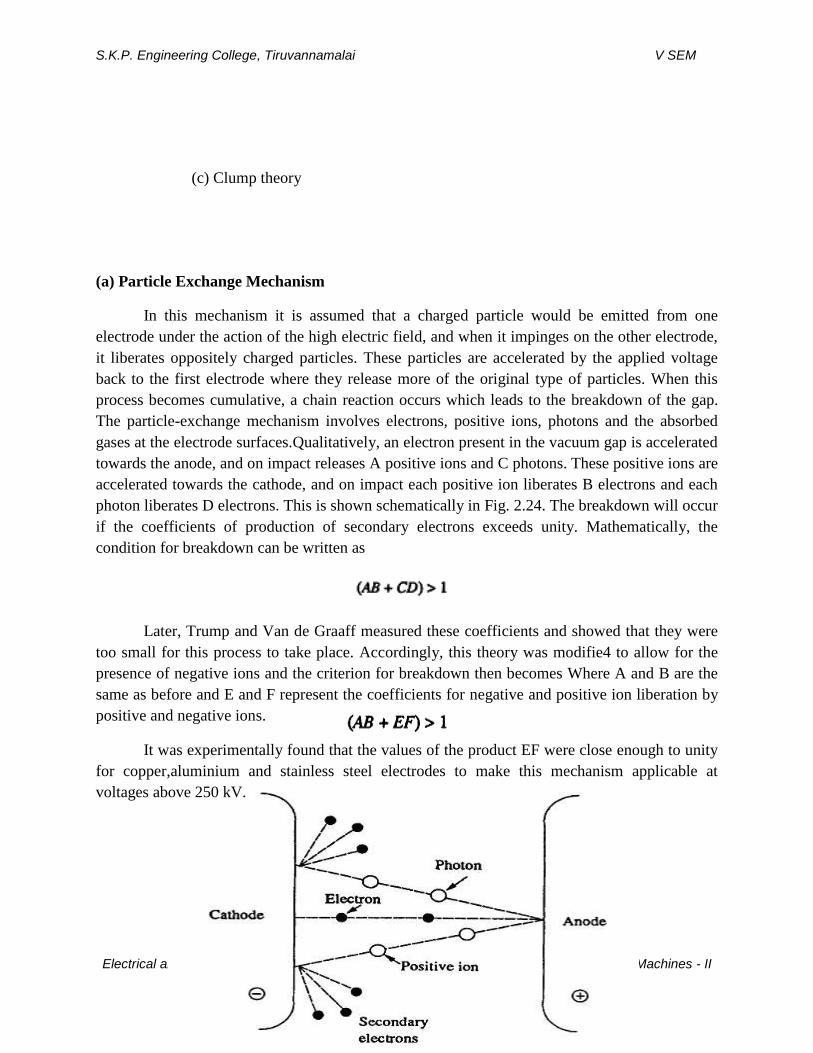
S.K.P. Engineering College, Tiruvannamalai V SEM
Electrical and Electronics Engineering Department 59 Electrical Machines - II
(c) Clump theory
(a) Particle Exchange Mechanism
In this mechanism it is assumed that a charged particle would be emitted from one
electrode under the action of the high electric field, and when it impinges on the other electrode,
it liberates oppositely charged particles. These particles are accelerated by the applied voltage
back to the first electrode where they release more of the original type of particles. When this
process becomes cumulative, a chain reaction occurs which leads to the breakdown of the gap.
The particle-exchange mechanism involves electrons, positive ions, photons and the absorbed
gases at the electrode surfaces.Qualitatively, an electron present in the vacuum gap is accelerated
towards the anode, and on impact releases A positive ions and C photons. These positive ions are
accelerated towards the cathode, and on impact each positive ion liberates B electrons and each
photon liberates D electrons. This is shown schematically in Fig. 2.24. The breakdown will occur
if the coefficients of production of secondary electrons exceeds unity. Mathematically, the
condition for breakdown can be written as
Later, Trump and Van de Graaff measured these coefficients and showed that they were
too small for this process to take place. Accordingly, this theory was modifie4 to allow for the
presence of negative ions and the criterion for breakdown then becomes Where A and B are the
same as before and E and F represent the coefficients for negative and positive ion liberation by
positive and negative ions.
It was experimentally found that the values of the product EF were close enough to unity
for copper,aluminium and stainless steel electrodes to make this mechanism applicable at
voltages above 250 kV.
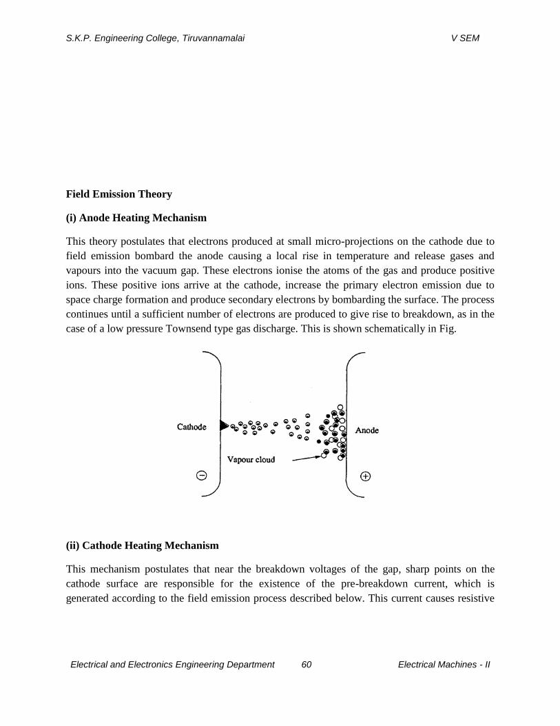
S.K.P. Engineering College, Tiruvannamalai V SEM
Electrical and Electronics Engineering Department 60 Electrical Machines - II
Field Emission Theory
(i) Anode Heating Mechanism
This theory postulates that electrons produced at small micro-projections on the cathode due to
field emission bombard the anode causing a local rise in temperature and release gases and
vapours into the vacuum gap. These electrons ionise the atoms of the gas and produce positive
ions. These positive ions arrive at the cathode, increase the primary electron emission due to
space charge formation and produce secondary electrons by bombarding the surface. The process
continues until a sufficient number of electrons are produced to give rise to breakdown, as in the
case of a low pressure Townsend type gas discharge. This is shown schematically in Fig.
(ii) Cathode Heating Mechanism
This mechanism postulates that near the breakdown voltages of the gap, sharp points on the
cathode surface are responsible for the existence of the pre-breakdown current, which is
generated according to the field emission process described below. This current causes resistive
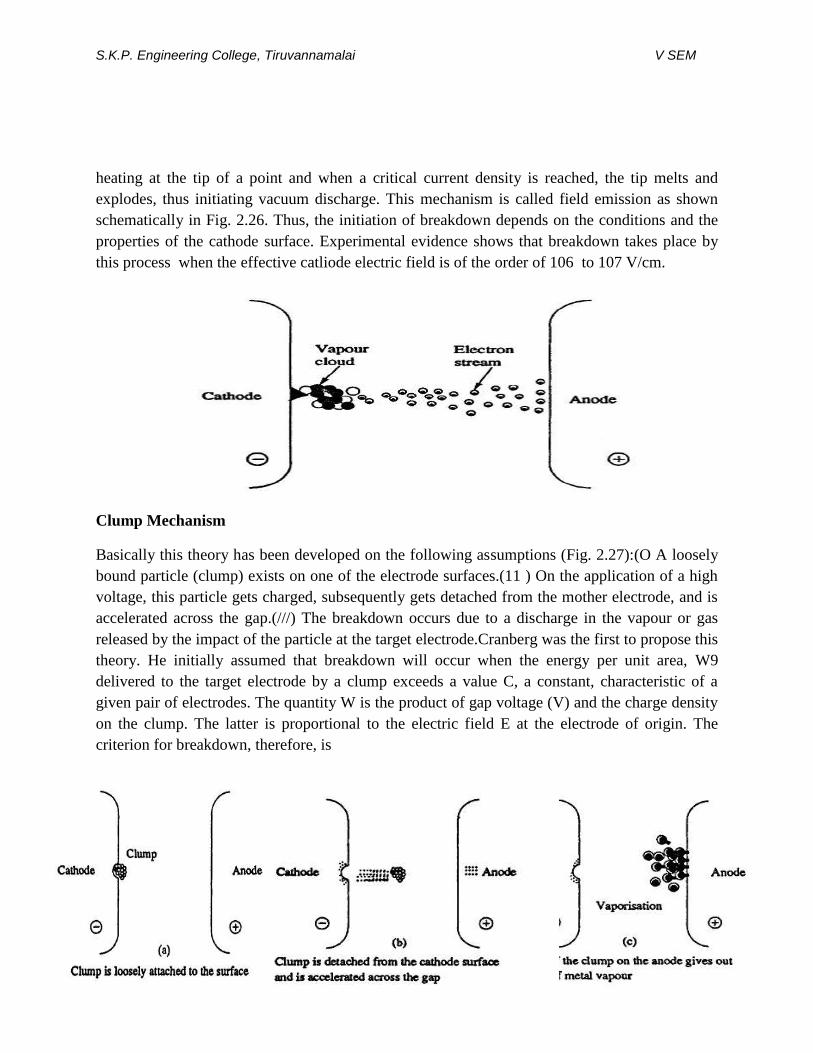
S.K.P. Engineering College, Tiruvannamalai V SEM
Electrical and Electronics Engineering Department 61 Electrical Machines - II
heating at the tip of a point and when a critical current density is reached, the tip melts and
explodes, thus initiating vacuum discharge. This mechanism is called field emission as shown
schematically in Fig. 2.26. Thus, the initiation of breakdown depends on the conditions and the
properties of the cathode surface. Experimental evidence shows that breakdown takes place by
this process when the effective catliode electric field is of the order of 106 to 107 V/cm.
Clump Mechanism
Basically this theory has been developed on the following assumptions (Fig. 2.27):(O A loosely
bound particle (clump) exists on one of the electrode surfaces.(11 ) On the application of a high
voltage, this particle gets charged, subsequently gets detached from the mother electrode, and is
accelerated across the gap.(///) The breakdown occurs due to a discharge in the vapour or gas
released by the impact of the particle at the target electrode.Cranberg was the first to propose this
theory. He initially assumed that breakdown will occur when the energy per unit area, W9
delivered to the target electrode by a clump exceeds a value C, a constant, characteristic of a
given pair of electrodes. The quantity W is the product of gap voltage (V) and the charge density
on the clump. The latter is proportional to the electric field E at the electrode of origin. The
criterion for breakdown, therefore, is
S.K.P. Engineering College, Tiruvannamalai V SEM
Electrical and Electronics Engineering Department 62 Electrical Machines - II
In case of parallel plane electrodes the field E = V/d, where d is the distance between the
electrodes. So the generalised criterion for breakdown becomes
where C is another constant involving C and the electrode surface conditions.Cranberg presented
a summary of the experimental results which satisfied this breakdown criterion with reasonable
accuracy. However the equation was later modified as V = C d01, where a varies between 0.2
and 1.2 depending on the gap length and the electrode material, with a maximum at 0.6. The
dependence of V on the electrode material, comes from the observations of markings on the
electrode surfaces. Craters were observed on the anode and melted regions on the cathode or
vice-versa after a single breakdown.
6.Explain the various characteristic in pure liquid dielectric. (CO2-L1-NOV2014)
CONDUCTION AND BREAKDOWN IN PURE LIQUIDS
When low electric fields less than 1 kV/cm are applied, conductivities of 10~18 -10"2 0
mho/cm are obtained. These are probably due to the impurities remaining after purification.
However, when the fields are high (> 100 kV/cm) the currents not only increase rapidly, but also
undergo violent fluctuations which will die down after some time. A typical mean value of the
conduction current in hexane is shown in Fig. 3.2.ReservoirTo vacuum pump Distillation column
To vacuum pump Test cell with electrodes Vacuum valve To vacuum pump The exact
mechanism of current growth is not known; however, it appears that the electrons are generated
from the cathode by field emission of electrons. The electrons so liberated get multiplied by a
process similar to Townsend's primary and secondary ionization in gases (see Chapter 2, Sees.
2.2, 2.3, 2.4). As the breakdown field is approached, the current increases rapidly due to a
process similar to the primary ionization process and also the positive ions reaching the cathode
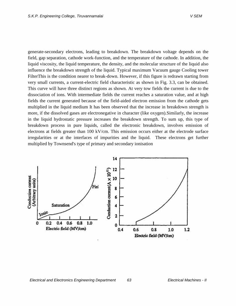
S.K.P. Engineering College, Tiruvannamalai V SEM
Electrical and Electronics Engineering Department 63 Electrical Machines - II
generate-secondary electrons, leading to breakdown. The breakdown voltage depends on the
field, gap separation, cathode work-function, and the temperature of the cathode. In addition, the
liquid viscosity, the liquid temperature, the density, and the molecular structure of the liquid also
influence the breakdown strength of the liquid. Typical maximum Vacuum gauge Cooling tower
FilterThis is the condition nearer to break-down. However, if this figure is redrawn starting from
very small currents, a current-electric field characteristic as shown in Fig. 3.3, can be obtained.
This curve will have three distinct regions as shown. At very tow fields the current is due to the
dissociation of ions. With intermediate fields the current reaches a saturation value, and at high
fields the current generated because of the field-aided electron emission from the cathode gets
multiplied in the liquid medium It has been observed that the increase in breakdown strength is
more, if the dissolved gases are electronegative in character (like oxygen).Similarly, the increase
in the liquid hydrostatic pressure increases the breakdown strength. To sum up, this type of
breakdown process in pure liquids, called the electronic breakdown, involves emission of
electrons at fields greater than 100 kV/cm. This emission occurs either at the electrode surface
irregularities or at the interfaces of impurities and the liquid. These electrons get further
multiplied by Townsend's type of primary and secondary ionisation
.
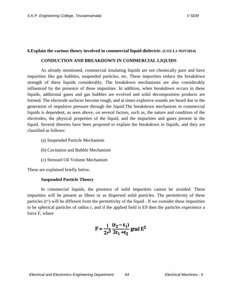
S.K.P. Engineering College, Tiruvannamalai V SEM
Electrical and Electronics Engineering Department 64 Electrical Machines - II
6.Explain the various theory involved in commercial liquid dielectric. (CO2-L1-NOV2014)
CONDUCTION AND BREAKDOWN IN COMMERCIAL LIQUIDS
As already mentioned, commercial insulating liquids are not chemically pure and have
impurities like gas bubbles, suspended particles, etc. These impurities reduce the breakdown
strength of these liquids considerably. The breakdown mechanisms are also considerably
influenced by the presence of these impurities. In addition, when breakdown occurs in these
liquids, additional gases and gas bubbles are evolved and solid decomposition products are
formed. The electrode surfaces become rough, and at times explosive sounds are heard due to the
generation of impulsive pressure through the liquid.The breakdown mechanism in commercial
liquids is dependent, as seen above, on several factors, such as, the nature and condition of the
electrodes, the physical properties of the liquid, and the impurities and gases present in the
liquid. Several theories have been proposed to explain the breakdown in liquids, and they are
classified as follows:
(a) Suspended Particle Mechanism
(b) Cavitation and Bubble Mechanism
(c) Stressed Oil Volume Mechanism
These are explained briefly below.
Suspended Particle Theory
In commercial liquids, the presence of solid impurities cannot be avoided. These
impurities will be present as fibres or as dispersed solid particles. The permittivity of these
particles (t^) will be different from the permittivity of the liquid . If we consider these impunities
to be spherical particles of radius r, and if the applied field is E9 then the particles experience a
force F, where
S.K.P. Engineering College, Tiruvannamalai V SEM
Electrical and Electronics Engineering Department 65 Electrical Machines - II
This force is directed towards areas of maximum stress, if 62 > EI for example, in thecase
of the presence of solid particles like paper in the liquid. On the other hand, if only gas bubbles
are present in the liquid, i.e. 62 < EI, the force will be in the direction of areas of lower stress. If
the voltage is continuously applied (d.c.) or the duration of the voltage is long (a.c.), then this
force drives the particles towards the areas of maximum stress. If the number of particles present
are large, they becomes aligned due to these forces, and thus form a stable chain bridging the
electrode gap causing a breakdown between the electrodes. If there is only a single conducting
particle between the electrodes, it will give rise to local field enhancement depending on its
shape. If this field exceeds the breakdown strength of the liquid, local breakdown will occur near
the particle, and this will result in the formation of gas bubbles which may lead to the breakdown
of the liquid. The vales of the breakdown strength of liquids containing solid impurities was
found to be much less than the values for pure liquids. The impurity particles reduce the
breakdown strength, and it was also observed that the larger the size of the particles the lower
were the breakdown strengths.
Cavitation and the Bubble Theory
It was experimentally observed that in many liquids, the breakdown strength depends
strongly on the applied hydrostatic pressure, suggesting that a change of phase of the medium is
involved in the breakdown process, which in other words means that a kind of vapour bubble
formed is responsible for breakdown. The following processes have been suggested to be
responsible for the formation of the vapour bubbles:
(a) Gas pockets at the surfaces of the electrodes; (b) electrostatic repulsive forces between space charges which may be sufficient to overcome the surface tension; (c) gaseous products due to the dissociation of liquid molecules by electron collisions; (d) vapourization of the liquid by corona type discharge from sharp points and irregularities on the electrode surfaces.
Once a bubble is formed it will elongate in the direction of the electric field under the
influence of electrostatic forces. The volume of the bubble remains constant during elongation.

S.K.P. Engineering College, Tiruvannamalai V SEM
Electrical and Electronics Engineering Department 66 Electrical Machines - II
Breakdown occurs when the voltage drop along the length of the bubble becomes equal to the
minimum value on the Paschen's curve for the gas in the bubble. The breakdown field is given as
This theory does not take into account the production of the initial bubble and hence the
results given by this theory do not agree well with the experimental results. This is shown in Fig.
3.6.Later this theory was modified, and it was suggested that only incompressible bubbles like
water globules can elongate at constant volume, according to the simple gas law pv = RT. Under
the influence of the applied electric field the shape of the globule is assumed to be approximately
a prolate spheroid. The incompressible bubbles reach the condition of instability when B, the
ratio of the longer to the shorter diameter of the spheriod, is about 1.85, and the critical field
producing the instability will be:
Thermal Mechanism of Breakdown
Another mechanism proposed to explain breakdown under pulse conditions is thermal
breakdown. This mechanism is based on the experimental observations of extremely large
currents just before breakdown. This high current pulses are believed to originate from the tips of
the microscopic projections on the cathode surface with densities of the order of 1 A/cm3 . These
high density current pulses give rise to localised heating of the oil which may lead to the
formation of vapour bubbles. The vapour bubbles are formed when the energy exceeds 10 W/cm
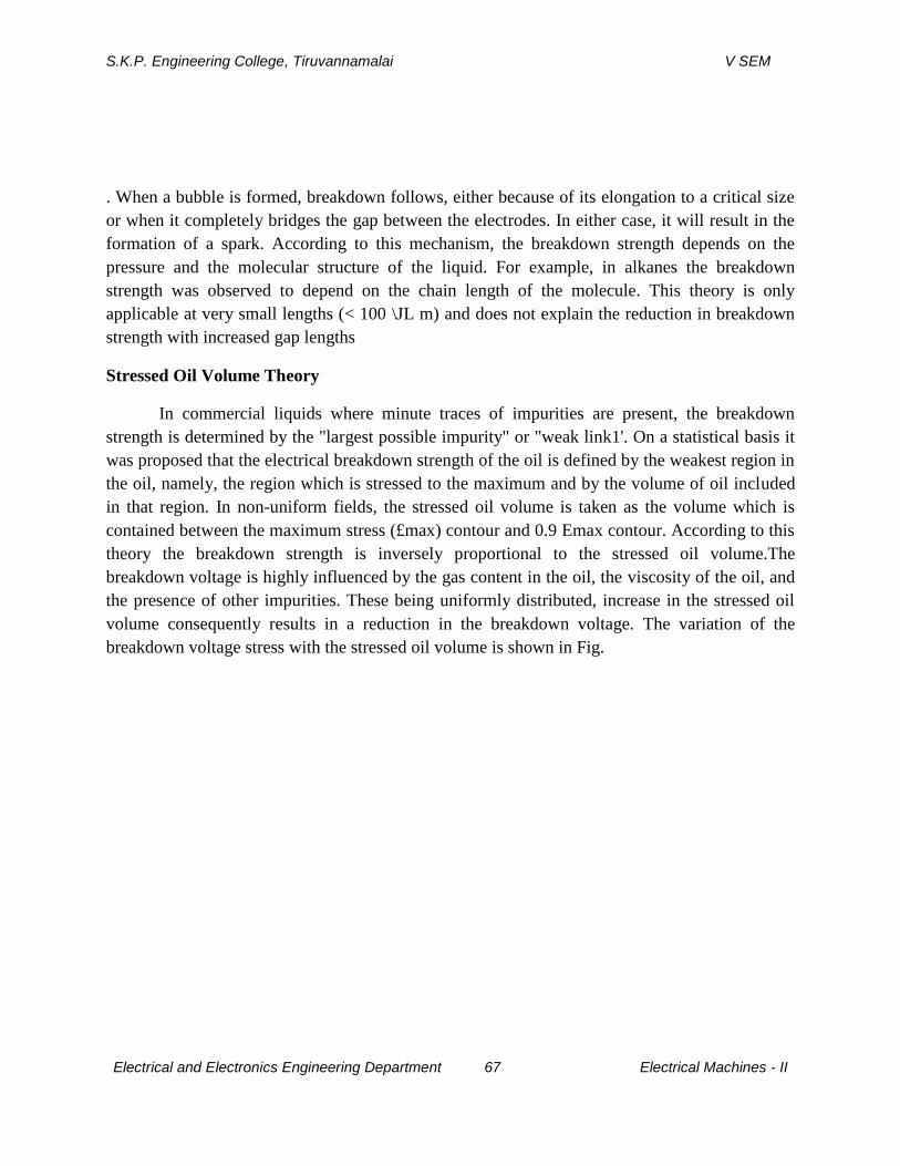
S.K.P. Engineering College, Tiruvannamalai V SEM
Electrical and Electronics Engineering Department 67 Electrical Machines - II
. When a bubble is formed, breakdown follows, either because of its elongation to a critical size
or when it completely bridges the gap between the electrodes. In either case, it will result in the
formation of a spark. According to this mechanism, the breakdown strength depends on the
pressure and the molecular structure of the liquid. For example, in alkanes the breakdown
strength was observed to depend on the chain length of the molecule. This theory is only
applicable at very small lengths (< 100 \JL m) and does not explain the reduction in breakdown
strength with increased gap lengths
Stressed Oil Volume Theory
In commercial liquids where minute traces of impurities are present, the breakdown
strength is determined by the "largest possible impurity" or "weak link1'. On a statistical basis it
was proposed that the electrical breakdown strength of the oil is defined by the weakest region in
the oil, namely, the region which is stressed to the maximum and by the volume of oil included
in that region. In non-uniform fields, the stressed oil volume is taken as the volume which is
contained between the maximum stress (£max) contour and 0.9 Emax contour. According to this
theory the breakdown strength is inversely proportional to the stressed oil volume.The
breakdown voltage is highly influenced by the gas content in the oil, the viscosity of the oil, and
the presence of other impurities. These being uniformly distributed, increase in the stressed oil
volume consequently results in a reduction in the breakdown voltage. The variation of the
breakdown voltage stress with the stressed oil volume is shown in Fig.
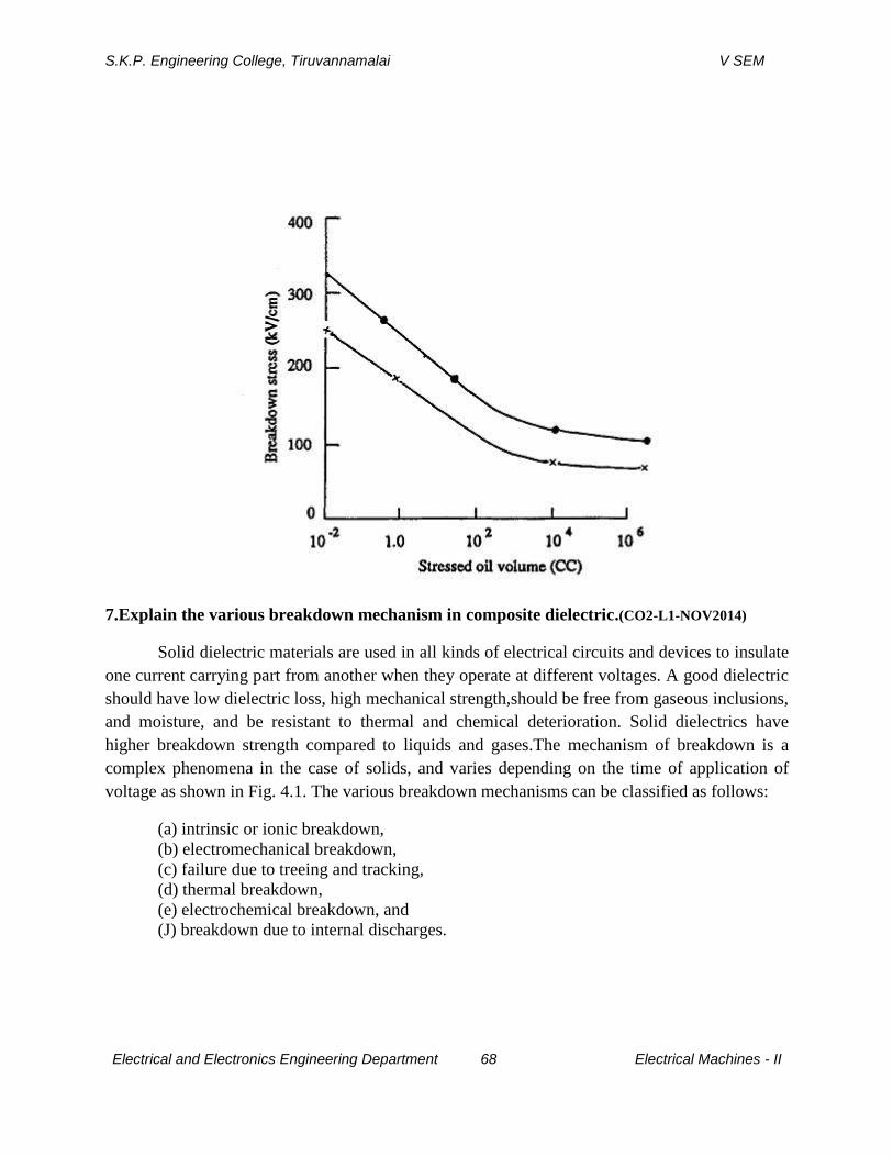
S.K.P. Engineering College, Tiruvannamalai V SEM
Electrical and Electronics Engineering Department 68 Electrical Machines - II
7.Explain the various breakdown mechanism in composite dielectric.(CO2-L1-NOV2014)
Solid dielectric materials are used in all kinds of electrical circuits and devices to insulate
one current carrying part from another when they operate at different voltages. A good dielectric
should have low dielectric loss, high mechanical strength,should be free from gaseous inclusions,
and moisture, and be resistant to thermal and chemical deterioration. Solid dielectrics have
higher breakdown strength compared to liquids and gases.The mechanism of breakdown is a
complex phenomena in the case of solids, and varies depending on the time of application of
voltage as shown in Fig. 4.1. The various breakdown mechanisms can be classified as follows:
(a) intrinsic or ionic breakdown,
(b) electromechanical breakdown,
(c) failure due to treeing and tracking,
(d) thermal breakdown,
(e) electrochemical breakdown, and
(J) breakdown due to internal discharges.
S.K.P. Engineering College, Tiruvannamalai V SEM
Electrical and Electronics Engineering Department 69 Electrical Machines - II
INTRINSICBREAKDOWN
When voltages are applied only for short durations of the order of 10""8S the dielectric
strength of a solid dielectric increases very rapidly to an upper limit called the intrinsic electric
strength. Experimentally, this highest dielectric strength can be obtained only under the best
experimental conditions when all extraneous influences have been isolated and the value depends
only on the structure of the material and the temperature. The maximum electrical strength
recorded is 15 MV/cm for poly vinyl-alcoholat - 1960C. The maximum strength usually
obtainable ranges from 5 MV/cm to 10MV/cm. Intrinsic breakdown depends upon the presence
of free electrons which are capable of migration through the lattice of the dielectric. Usually, a
small number of conduction elections are present in solid dielectrics, along with some structural
imperfections and small amounts of impurities. The impurity atoms, or molecules or both act as
traps for the conduction electrons up to certain ranges of electric fields and temperatures. When
these ranges are exceeded, additional electrons in addition to trapped electrons are released, and
these electrons participate in the conduction process. Based on this principle, two types of
intrinsic breakdown mechanisms have been proposed.
Electronic Breakdown
As mentioned earlier, intrinsic breakdown occurs in time of the order of 10~8s and
therefore is assumed to be electronic in nature. The initial density of conduction (free) electrons
is also assumed to be large, and electron-electron collisions occur. When an electric field is
applied, electrons gain energy from the electric field and cross the forbidden energy gap from the
valency to the conduction band. When this process is repeated, more and more electrons become
available in the conduction band, eventually leading to breakdown.
Avalanche or Streamer Breakdown
This is similar to breakdown in gases due to cumulative ionization. Conduction electrons
gain sufficient energy above a certain critical electric field and cause liberation of electrons from
the lattice atoms by collisions. Under uniform field conditions, if the electrodes are embedded in
the specimen, breakdown will occur when an electron avalanche bridges the electrode gap. An
electron within the dielectric, starting from the cathode will drift towards the anode and during
this motion gains energy from the field and loses it during collisions. When the energy gained by
an electron exceeds the lattice ionization potential, and additional electron will be liberated due
to collision of the first electron. This process repeats itself resulting in the formation of an
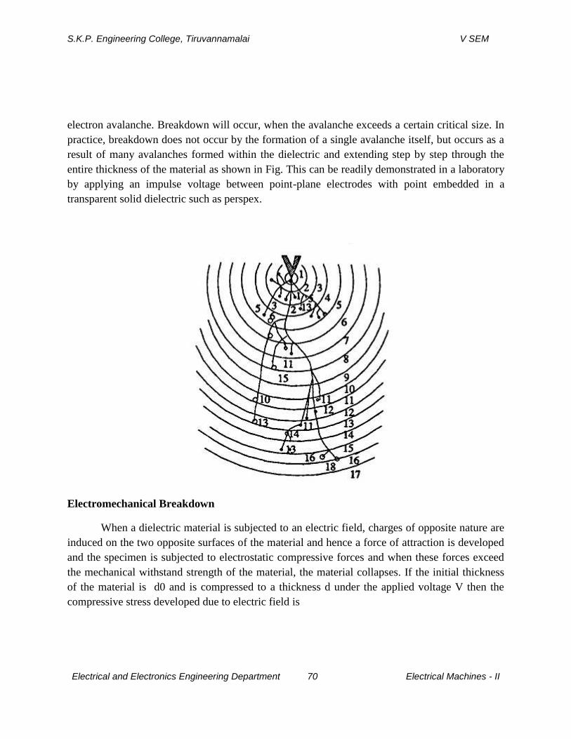
S.K.P. Engineering College, Tiruvannamalai V SEM
Electrical and Electronics Engineering Department 70 Electrical Machines - II
electron avalanche. Breakdown will occur, when the avalanche exceeds a certain critical size. In
practice, breakdown does not occur by the formation of a single avalanche itself, but occurs as a
result of many avalanches formed within the dielectric and extending step by step through the
entire thickness of the material as shown in Fig. This can be readily demonstrated in a laboratory
by applying an impulse voltage between point-plane electrodes with point embedded in a
transparent solid dielectric such as perspex.
Electromechanical Breakdown
When a dielectric material is subjected to an electric field, charges of opposite nature are
induced on the two opposite surfaces of the material and hence a force of attraction is developed
and the specimen is subjected to electrostatic compressive forces and when these forces exceed
the mechanical withstand strength of the material, the material collapses. If the initial thickness
of the material is d0 and is compressed to a thickness d under the applied voltage V then the
compressive stress developed due to electric field is
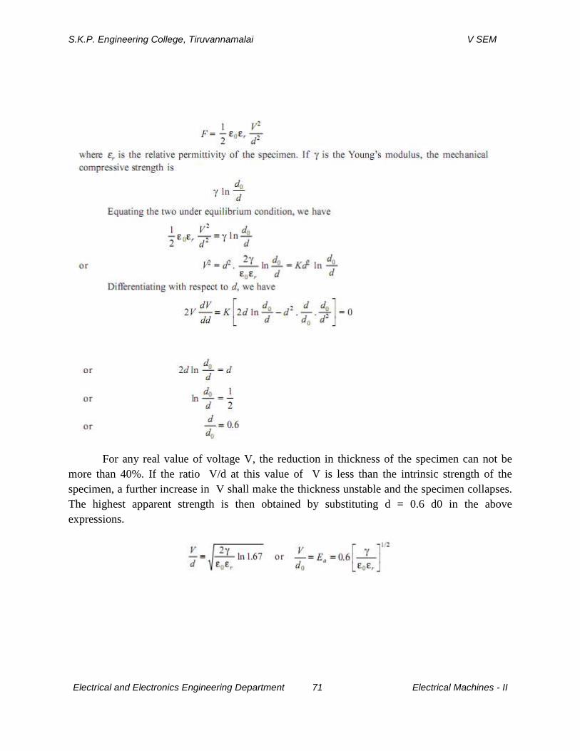
S.K.P. Engineering College, Tiruvannamalai V SEM
Electrical and Electronics Engineering Department 71 Electrical Machines - II
For any real value of voltage V, the reduction in thickness of the specimen can not be
more than 40%. If the ratio V/d at this value of V is less than the intrinsic strength of the
specimen, a further increase in V shall make the thickness unstable and the specimen collapses.
The highest apparent strength is then obtained by substituting d = 0.6 d0 in the above
expressions.
S.K.P. Engineering College, Tiruvannamalai V SEM
Electrical and Electronics Engineering Department 72 Electrical Machines - II
The above equation is approximate only as γ depends upon the mechanical stress. The
possibility of instability occuring for lower average field is ignored i.e., the effect of stress
concentration at irregularities is not taken into account.
Breakdown due to Treeing and Tracking
We know that the strength of a chain is given by the strength of the weakest link in the
chain. Similarly whenever a solid material has some impurities in terms of some gas pockets or
liquid pockets in it the dielectric strength of the solid will be more or less equal to the strength of
the weakest impurities. Suppose some gas pockets are trapped in a solid material during
manufacture, the gas has a relative permittivity of unity and the solid material εr, the electric
field in the gas will be εr times the field in the solid material. As a result, the gas breaks down at
a relatively lower voltage. The charge concentration there in the void will make the field more
non-uniform. The charge concentration in such voids is found to be quite large to give fields of
the order of 10 MV/cm which is higher than even the intrinsic breakdown.These charge
concentrations at the voids within the dielectric lead to breakdown step by step and finally lead
to complete rupture of the dielectric. Since the breakdown is not caused by a single discharge
channel and assumes a tree like structure as shown in Fig.it is known as breakdown due to
treeing. The treeing phenomenon can be readily demonstrated in a laboratory by applying an
impulse voltage between point plane electrodes with the point embedded in a transparent solid
dielectric such as perspex. The treeing phenomenon can be observed in all dielectric wherever
non-uniform fields prevail. Suppose we have two electrodes separated by an insulating material
and the assembly is placed in an outdoor environment. Some contaminants in the form of
moisture or dust particles will get deposited on the surface of the insulation and leakage current
starts between the electrode through the contaminants say moisture. The current heats the
moisture and causes breaks in the moisture films. These small films then act as electrodes and
sparks are drawn between the films. The sparks cause carbonization and volatilization of the
insulation and lead to formation of permanent carbon tracks on the surface of insulations.
Therefore, tracking is the formation of a permanent conducting path usually carbon across the
surface of insulation. For tracking to occur, the insulating material must contain organic
substances. For this reason, for outdoor equipment, tracking severely limits the use of insulation
having organic substances. The rate of tracking can be slowed down by adding filters to the
polymers which inhibit carbonization.
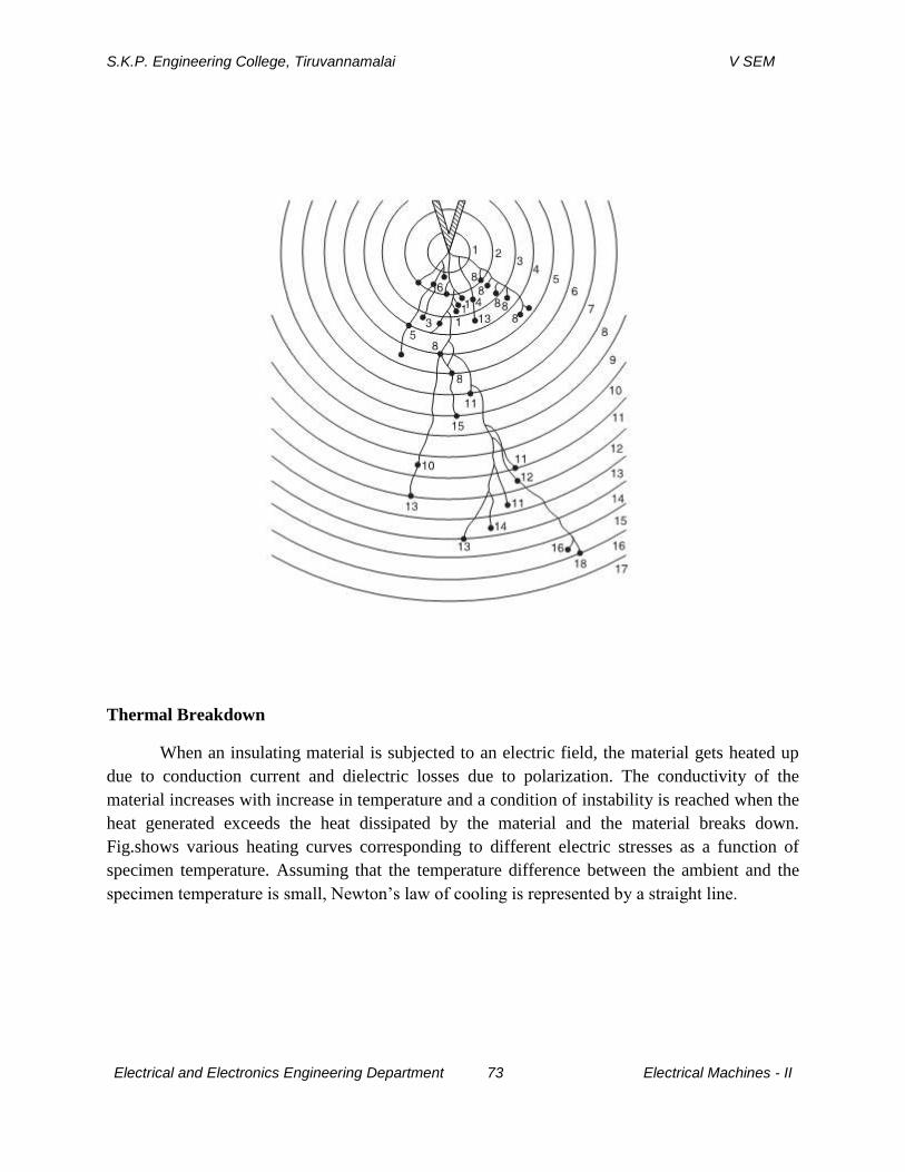
S.K.P. Engineering College, Tiruvannamalai V SEM
Electrical and Electronics Engineering Department 73 Electrical Machines - II
Thermal Breakdown
When an insulating material is subjected to an electric field, the material gets heated up
due to conduction current and dielectric losses due to polarization. The conductivity of the
material increases with increase in temperature and a condition of instability is reached when the
heat generated exceeds the heat dissipated by the material and the material breaks down.
Fig.shows various heating curves corresponding to different electric stresses as a function of
specimen temperature. Assuming that the temperature difference between the ambient and the
specimen temperature is small, Newton’s law of cooling is represented by a straight line.
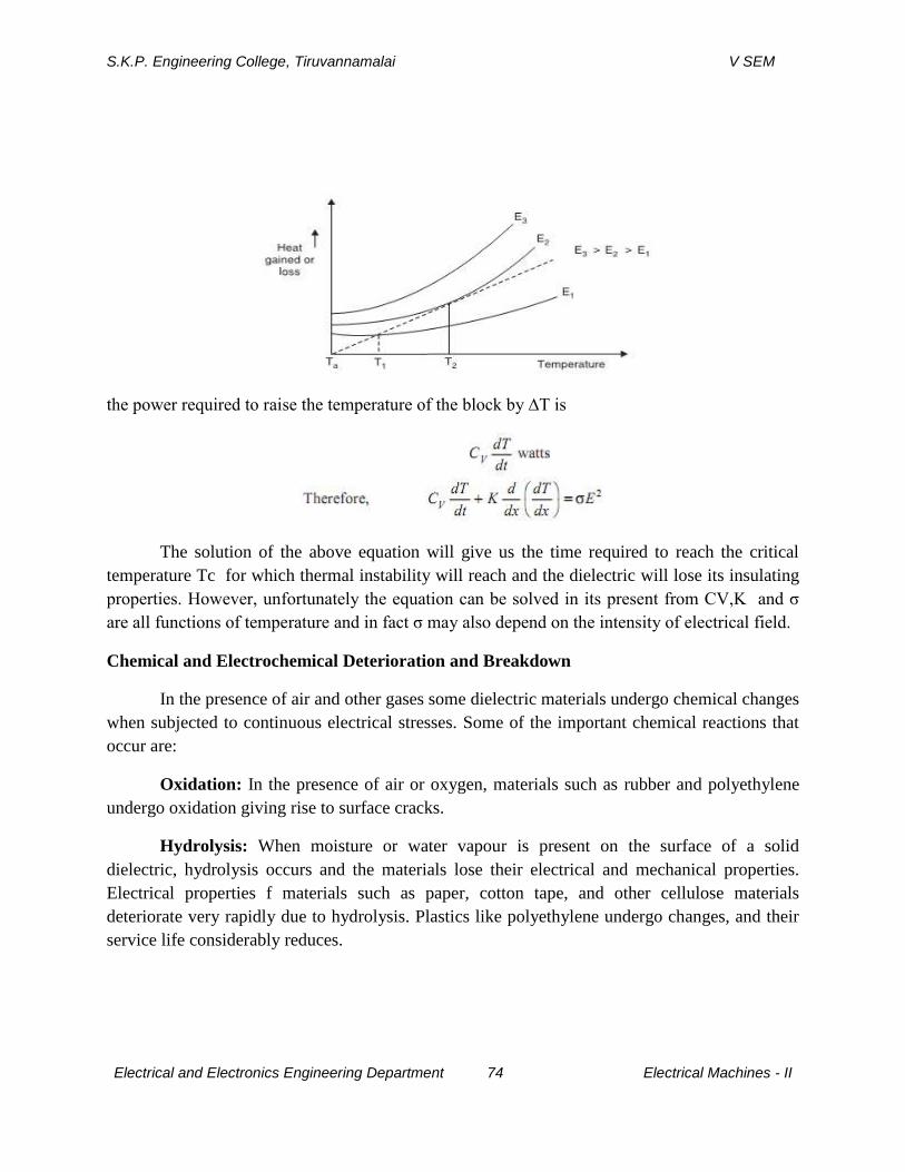
S.K.P. Engineering College, Tiruvannamalai V SEM
Electrical and Electronics Engineering Department 74 Electrical Machines - II
the power required to raise the temperature of the block by ∆T is
The solution of the above equation will give us the time required to reach the critical
temperature Tc for which thermal instability will reach and the dielectric will lose its insulating
properties. However, unfortunately the equation can be solved in its present from CV,K and ζ
are all functions of temperature and in fact ζ may also depend on the intensity of electrical field.
Chemical and Electrochemical Deterioration and Breakdown
In the presence of air and other gases some dielectric materials undergo chemical changes
when subjected to continuous electrical stresses. Some of the important chemical reactions that
occur are:
Oxidation: In the presence of air or oxygen, materials such as rubber and polyethylene
undergo oxidation giving rise to surface cracks.
Hydrolysis: When moisture or water vapour is present on the surface of a solid
dielectric, hydrolysis occurs and the materials lose their electrical and mechanical properties.
Electrical properties f materials such as paper, cotton tape, and other cellulose materials
deteriorate very rapidly due to hydrolysis. Plastics like polyethylene undergo changes, and their
service life considerably reduces.

S.K.P. Engineering College, Tiruvannamalai V SEM
Electrical and Electronics Engineering Department 75 Electrical Machines - II
Chemical Action: Even in the absence of electric fields, progressive chemical
degradation of insulating materials can occur due to a variety of processes such as chemical
instability at high temperatures, oxidation and cracking in the presence of air and ozone, and
hydrolysis due to moisture and heat. Since different insulating materials come into contact with
each other in any practical apparatus, chemical reactions occur between these various materials
leading to reduction in electrical and mechanical strengths resulting in failure.The effects of
electrochemical and chemical deterioration could be minimized by carefully studying and
examining the materials. High soda content glass insulation should be avoided in moist and
damp conditions, because sodium, being very mobile,leaches to the surface giving rise to the
formation of a strong alkali which will cause deterioration. It was observed that this type of
material will lose its mechanical strength within 24 hrs, when it is explosed to atmospheres
havjng 100% relative humidity at 7O0 C. In paper insulation, even if partial discharges are
prevented completely, breakdown can occur due to chemical degradation. The chemical and
electrochemical deterioration increases very rapidly with temperature, and hence high
temperatures should be avoided.
Breakdown Due to Internal Discharges
Solid insulating materials, and to a lesser extent liquid dielectrics contain voids or
cavities within the medium or at the boundaries between the dielectric and the electrodes. These
voids are generally filled with a medium of lower dielectric strength, and the dielectric constant
of the medium in the voids is lower than that of the insulation. Hence, the electric field strength
in the voids is higher than that across the dielectric. Therefore, even under normal working
voltages the field in the voids may exceed their breakdown value, and breakdown may occur. Let
us consider a dielectric between two conductors as shown in Fig. 4.5a. If we divide the insulation
into three parts, an electrical network of C1, C2 and C3can be formed as shown in Fig. In this C1
represents the capacitance of the void or cavity, C2 is the capacitance of the dielectric which is in
series with the void, and C3 is the capacitance of the rest of the dielectric. When the applied
voltage is V, the voltage across the void, F1 is given by the same equation
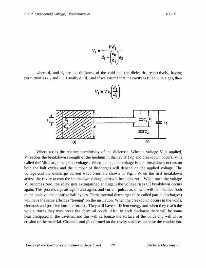
S.K.P. Engineering College, Tiruvannamalai V SEM
Electrical and Electronics Engineering Department 76 Electrical Machines - II
where d1 and d2 are the thickness of the void and the dielectric, respectively, having
permittivities ɛ 0 and ɛ 1. Usually d1<d2 ,and if we assume that the cavity is filled with a gas, then
Where ɛ r is the relative permittivity of the dielectric. When a voltage V is applied,
V1reaches the breakdown strength of the medium in the cavity (Vj) and breakdown occurs. Vi is
called the' 'discharge inception voltage''. When the applied voltage is a.c., breakdown occurs on
both the half cycles and the number of discharges will depend on the applied voltage. The
voltage and the discharge current waveforms are shown in Fig. . When the first breakdown
across the cavity occurs the breakdown voltage across it becomes zero. When once the voltage
VI becomes zero, the spark gets extinguished and again the voltage rises till breakdown occurs
again. This process repeats again and again, and current pulses as shown, will be obtained both
in the positive and negative half cycles. These internal discharges (also called partial discharges)
will have the same effect as "treeing" on the insulation. When the breakdown occurs in the voids,
electrons and positive ions are formed. They will have sufficient energy and when they reach the
void surfaces they may break the chemical bonds. Also, in each discharge there will be some
heat dissipated in the cavities, and this will carbonize the surface of the voids and will cause
erosion of the material. Channels and pits formed on the cavity surfaces increase the conduction.
S.K.P. Engineering College, Tiruvannamalai V SEM
Electrical and Electronics Engineering Department 77 Electrical Machines - II
Chemical degradation may also occur as a result of the active discharge products formed during
breakdown. All these effects will result in a gradual erosion of the material and consequent
reduction in the thickness of insulation leading to breakdown. The life of the insulation with
internal discharges depends upon the applied voltage and the number of discharges. Breakdown
by this process may occur in a few days or may take a few years.
8.Explain the various breakdown mechanism in composite dielectric. (CO2-L1-NOV2014)
BREAKDOWN IN COMPOSITE DIELECTRICS
Properties of Composite Dielectrics
A composite dielectric generally consists of a large number of layers arranged one over the other.
This is called "the layered construction" and is widely used in cables,capacitors and transformers.
Three properties of composite dielectrics which are important to their performance are given
below.
(a) Effect of Multiple Layers
The simplest composite dielectric consists of two layers of the same material. Here,advantage is
taken of the fact that two thin sheets have a higher dielectric strength than a single sheet of the
same total thickness. The advantage is particularly significant in the case of materials having a
wide variation in dielectric strength values measured at different points on its surface.
(b) Effect of Layer Thickness
Increase in layer thickness normally gives increased breakdown voltage. In a layered
construction, breakdown channels occur at the interfaces only and not directly through another
layer. Also, a discharge having penetrated one layer cannot enter the next layer until a part of the
interface also attains the potential which can produce an electric field stress comparable to that of
the discharge channel. The use of layered construction is very important in the case of insulating
paper since the paper thickness itself varies from point to point and consequently the dielectric
strength across its surface is not homogeneous. The differences in the thickness impart a rough
surface to the paper which can produce an electric field stress comparable to that of the discharge
channel. The rough surface of the paper also helps in better impregnation when tightly wound.
On the other hand, the existence of areas with lower thickness in the paper can cause breakdown
S.K.P. Engineering College, Tiruvannamalai V SEM
Electrical and Electronics Engineering Department 78 Electrical Machines - II
at these points at considerably lower voltages. Various investigations on composite dielectrics
have shown that
(i) the discharge inception voltage depends on the thickness of the solid dielectric, as
well as on the dielectric constant of both the liquid and solid dielectric, and
(ii) the difference in the dielectric constants between the liquid and solid dielectrics
does not significantly affect the rate of change of electric field at the electrode
edge with the change in the dielectric thickness.
(c) Effect of Interfaces
The interface between two dielectric surfaces in a composite dielectric system plays an
important role in determining its pre-breakdown and breakdown strengths. Discharges usually
occur at the interfaces and the magnitude of the discharge depends on the associated surface
resistance and capacitance. When the surface conductivity increases, the discharge magnitude
also increases, resulting in damage to the dielectric.In a composite dielectric, it is essential to
maintain low dielectric losses because they normally operate at high electric stresses. However,
even in an initially pure dielectric liquid, when used under industrial conditions for impregnating
solid dielectrics, impurities arise, resulting in increased dielectric losses.
Mechanisms of Breakdown in Composite Dielectrics
As mentioned in the earlier section, if dielectric losses are low the cumulative heat
produced will be low and thermal breakdown will not occur. However, several other factors can
cause short and long time breakdown.
(a) Short-Term Breakdown
If the electric field stresses are very high, failure may occur in seconds or even faster
without any substantial damage to the insulating surface prior to breakdown. It has been
observed that breakdown results from one or more discharges when the applied voltage is close
to the observed breakdown value. There exists a critical stress in the volume of the dielectric at
which discharges of a given magnitude can enter the insulation from the surface and propagate
rapidly into its volume to cause breakdown. Experiments with single discharges on an insulating
material have shown that breakdown occurs more rapidly when the electric field in the insulation
is such that it assists the charged particles in the discharge to penetrate into the insulation, than

S.K.P. Engineering College, Tiruvannamalai V SEM
Electrical and Electronics Engineering Department 79 Electrical Machines - II
when the field opposes their entry. Breakdown was observed to occur more readily when the
bombarding particles are electrons, rather than positive ions. In addition, there are local field
intensifications due to the presence of impurities and variations in the thickness of solid
insulation and these local field intensifications play a very important role in causing breakdown
under high field conditions; the actual effect being dependent on the field in the insulation before
the discharge impinges on it.
(b) Long-Term Breakdown
Long-term breakdown is also called the ageing of insulation. The principal effects
responsible for the ageing of the insulation which eventually leads to breakdown arise from the
thermal processes and partial discharges. Partial discharges normally occur within the volume of
the composite insulation systems. In addition, the charge accumulation and conduction on the
surface of the insulation also contributes significantly towards the ageing and failure of
insulation.
(i) Ageing and breakdown due to partial discharges
During the manufacture of composite insulation, gas filled cavities will be present within
the dielectric or adjacent to the interface between the conductor and the dielectric. When a
voltage is applied to such a system, discharges occur within the gas-filled cavities. These
discharges are called the *'partial discharges" and involve the transfer of electric charge between
the two points in sufficient quantity to cause the discharge of the local capacitance. At a given
voltage, the impact of this charge on the dielectric surface produces a deterioration of the
insulating properties, in many ways, depending on the geometry of the cavity and the nature of
the dielectric. The study of breakdown by partial discharges is very important in industrial
systems.The degree of ageing depends on the discharge inception voltage, VI and the discharge
magnitude. It has been shown that K1- is strongly dependent on the permittivity of the dielectric
er and the thickness of the cavity g. VI can be estimated approximately by
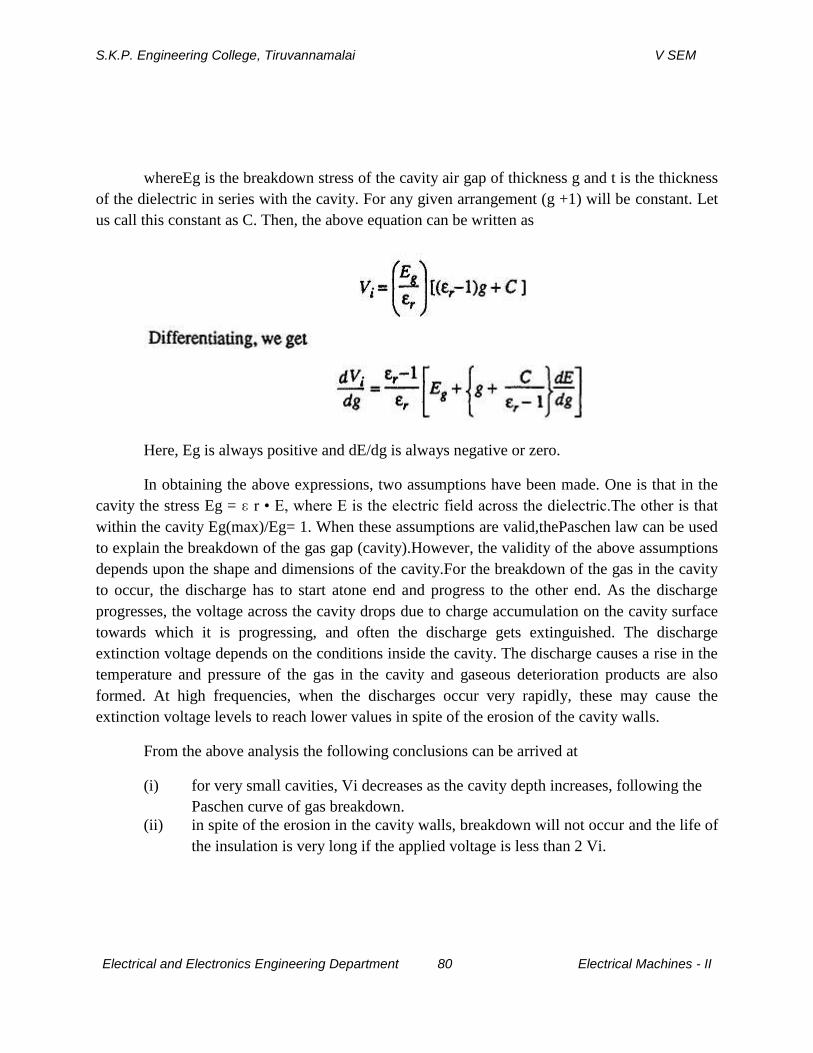
S.K.P. Engineering College, Tiruvannamalai V SEM
Electrical and Electronics Engineering Department 80 Electrical Machines - II
whereEg is the breakdown stress of the cavity air gap of thickness g and t is the thickness
of the dielectric in series with the cavity. For any given arrangement (g +1) will be constant. Let
us call this constant as C. Then, the above equation can be written as
Here, Eg is always positive and dE/dg is always negative or zero.
In obtaining the above expressions, two assumptions have been made. One is that in the
cavity the stress Eg = ɛ r • E, where E is the electric field across the dielectric.The other is that
within the cavity Eg(max)/Eg= 1. When these assumptions are valid,thePaschen law can be used
to explain the breakdown of the gas gap (cavity).However, the validity of the above assumptions
depends upon the shape and dimensions of the cavity.For the breakdown of the gas in the cavity
to occur, the discharge has to start atone end and progress to the other end. As the discharge
progresses, the voltage across the cavity drops due to charge accumulation on the cavity surface
towards which it is progressing, and often the discharge gets extinguished. The discharge
extinction voltage depends on the conditions inside the cavity. The discharge causes a rise in the
temperature and pressure of the gas in the cavity and gaseous deterioration products are also
formed. At high frequencies, when the discharges occur very rapidly, these may cause the
extinction voltage levels to reach lower values in spite of the erosion of the cavity walls.
From the above analysis the following conclusions can be arrived at
(i) for very small cavities, Vi decreases as the cavity depth increases, following the
Paschen curve of gas breakdown.
(ii) in spite of the erosion in the cavity walls, breakdown will not occur and the life of
the insulation is very long if the applied voltage is less than 2 Vi.
S.K.P. Engineering College, Tiruvannamalai V SEM
Electrical and Electronics Engineering Department 81 Electrical Machines - II
(iii) for applied voltages greater than 2V corosion is faster and therefore ageing of the
insulation is quicker.
(iv) the total capacitance of the cavity is not discharged as a single event but a result
of any discharges, each discharge involving only a small area of the cavity wall
determined by the conductivity of the cavity surface in the region of the
discharge.
(ii) Ageing and breakdown due to accumulation of charges on insulator surfaces
During discharges at the solid or liquid or solid-gas or solid-vacuum interfaces, certain
quantity of charge (electrons or positive ions) gets deposited on the solid insulator surface. The
charge thus deposited can stay there for very long durations, lasting for days or even weeks. The
presence of this charge increases the surface conductivity thereby increasing the discharge
magnitude in subsequent discharges. Increased discharge magnitude in subsequent discharges
causes damage to the dielectric surface. Experiments using electro-photography and other
methods have shown that transverse discharges occur on the faces of the dielectric, and these
discharges cause a large area to be discharged instantaneously. Charges that exist in surface
conductivity are due to the discharges themselves such that changes in discharge magnitude will
occur spontaneously during the life of a dielectric. It has been generally observed that the
discharge characteristics change with the life of the insulation. This can be explained as follows:
for clean surfaces, at the discharge inception voltage V/f the discharge characteristic depends on
the nature of the dielectric, its size and shape. The discharge normally consists of a large number
of comparatively small discharges originating from sites on the insulator surface where the
necessary discharge condition exists. After some time, erosion at these sites causes the
discharges to decrease in number as well as in magnitude, and consequently total extinction may
occur. With the passage of time, the phenomena involved become complex because the charges
from the surface-induced conductivity add to the charge accumulation in the bulk due to partial
discharges.
9.Explain the maintenance of oil quality with neat diagram(CO2-L1-NOV2014)
The oil is poured in a container known as test-cell which has internal dimensions of 55 mm
× 90 mm× 100 mm high. The electrodes are polished spheres of 12.7 to 13 mm diameter,
preferably of brass,arranged horizontally with their axis not less than 40 mm above the bottom of

S.K.P. Engineering College, Tiruvannamalai V SEM
Electrical and Electronics Engineering Department 82 Electrical Machines - II
the cell. For the test, the is distance between the spheres shall be 4 + 0.02 mm. A suitable gauge
is used to adjust the gap. While preparing the oil sample, the test-cell should be thoroughly
cleaned and the moisture and suspended particles should be avoided. Fig. 1.13 shows an
experimental set-up for finding out the dielectric strength of the given sample of oil. The
voltmeter is connected on to the primary side of the high voltage transformer but calibrated on
the high voltage side.
The gap between the spheres is adjusted to 4 mm with the help of a gauge and the spheres
areimmersed in oil to a depth as mentioned earlier. The voltage is increased gradually and
continuously till
a flash over of the gap is seen or the MCB operates. Note down this voltage. This voltage is
known as rapidly-applied voltage. The breakdown of the gap has taken place mainly due to field
effect. The thermal effect is minimal as the time of application is short.Next bring the voltage
back to zero and start with 40% of the rapidly applied voltage and wait for one minute. See if the
gap has broken. If not, increase the voltage everytime by 2.1/2% of the rapidly applied voltage
and wait for one minute till the flash over is seen or the MCB trips. Note down this voltage.Start
again with zero voltage and increase the voltage to a value just obtained in the previous step and
wait for a minute. It is expected that the breakdown will take place. A few trials around this point
will give us the breakdown value of the dielectric strength. The acceptable value is 30 kV for
4mm applied for one minute. In fact these days transformer oils with 65 kV for 4 mm 1 minute
value are available. If it is less than 30 kV, the oil should be sent for reconditioning. It is to be
S.K.P. Engineering College, Tiruvannamalai V SEM
Electrical and Electronics Engineering Department 83 Electrical Machines - II
noted that if the electrodes are immersed vertically in the oil, the dielectric strength measured
may turn out to be lower than what we obtained by placing the electrodes in horizontal position
which is the normal configuration. It is due to the fact that when oil decomposes carbon particles
being lighter rise up and if theelectrodes are in vertical configuration, these will bridge the gap
and the breakdown will take place ata relatively lower value.
Application of Oil in Power Apparatus
Oil is normally used for providing insulation between the live parts of different phases
and between phases and the grounded enclosure containing the oil and the main parts of the
apparatus. Also it provides cooling effect to the apparatus placed within the enclosure. Besides
providing insulation, the oil helps the C.B. to quench the arc produced between the breaker
contacts when they begin to separate to eliminate the faulted section from the healthy section of
the system.
The temperature about the arc is too high for the three last-named gases to exist and the
arc itself runs into a mixture of hydrogen, carbon and copper vapour at temperature above 6000
K. The hydrogen being a diatomic gas gets dissociated into the atomic state which changes the
characteristics of the arcon account of its associated change in its thermal conductivity. The
outcome of this is that the discharge suddenly contracts and acquires an appreciably higher core
temperature. In certain cases, the thermal ionization may be so great that the discharge runs with
a lower voltage which may stop the ionization due to the electric field strength. The transition
from the field ionization to thermal ionization is most marked in hydrogen and, therefore, in oil
circuit breakers.
UNIT III
S.K.P. Engineering College, Tiruvannamalai V SEM
Electrical and Electronics Engineering Department 84 Electrical Machines - II
GENERATION OF HIGH VOLTAGES AND HIGH CURRENTS
PART A
1. Give some uses of HVDC. (CO3-L1-MAY2012)
Generation of high d.c voltages is mainly required in research work in the areas of
pure and applied physics. Sometimes high direct voltages are needed in insulation
tests on cables and capacitors. Impulse generator charging units also require HVDC
of about 100 to 200 kV. Normally for the generation of dc voltages of up to and the
output currents are about 100 mA.
2. What are the applications of impulse current wave forms of high magnitude?
(CO3-L1-MAY2012)
Generation of impulse current waveforms of high magnitude (100 kA peak) find
application in test work as well as in basic research or non linear resistors, electric
arc studies relating to electric plasmas in high current discharges.
3. How are capacitances connected in an impulse current generator? (CO3-L1-
MAY2012)
For producing impulse currents of large value a bank of capacitors are connected in
parallel and are charged to a specified value and are discharged through a series R.L
circuit.
4. What type of wave form will be available in impulse current generator output?
(CO3-L1-MAY2012)
Damped wave or damped oscillatory wave.
5. Draw a circuit diagram of simple voltage doublers. (CO3-L1-MAY2012)
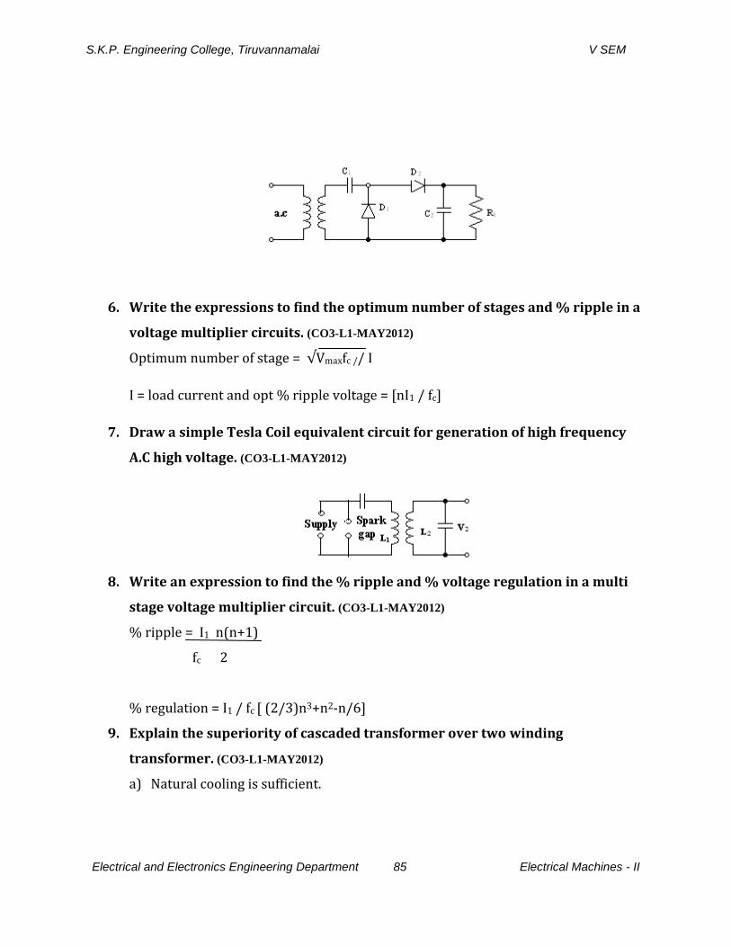
S.K.P. Engineering College, Tiruvannamalai V SEM
Electrical and Electronics Engineering Department 85 Electrical Machines - II
6. Write the expressions to find the optimum number of stages and % ripple in a
voltage multiplier circuits. (CO3-L1-MAY2012)
Optimum number of stage = √Vmaxfc // I
I = load current and opt % ripple voltage = [nI1 / fc]
7. Draw a simple Tesla Coil equivalent circuit for generation of high frequency
A.C high voltage. (CO3-L1-MAY2012)
8. Write an expression to find the % ripple and % voltage regulation in a multi
stage voltage multiplier circuit. (CO3-L1-MAY2012)
% ripple = I1 n(n+1)
fc 2
% regulation = I1 / fc [ (2/3)n3+n2-n/6]
9. Explain the superiority of cascaded transformer over two winding
transformer. (CO3-L1-MAY2012)
a) Natural cooling is sufficient.
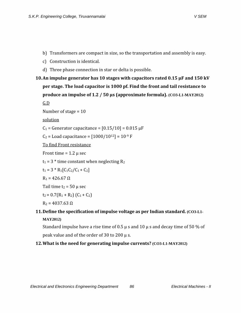
S.K.P. Engineering College, Tiruvannamalai V SEM
Electrical and Electronics Engineering Department 86 Electrical Machines - II
b) Transformers are compact in size, so the transportation and assembly is easy.
c) Construction is identical.
d) Three phase connection in star or delta is possible.
10. An impulse generator has 10 stages with capacitors rated 0.15 µF and 150 kV
per stage. The load capacitor is 1000 pf. Find the front and tail resistance to
produce an impulse of 1.2 / 50 µs (approximate formula). (CO3-L1-MAY2012)
G.D
Number of stage = 10
solution
C1 = Generator capacitance = [0.15/10] = 0.015 µF
C2 = Load capacitance = [1000/1012] = 10-9 F
To find Front resistance
Front time = 1.2 µ sec
t1 = 3 * time constant when neglecting R2
t1 = 3 * R1[C1C2/C1 + C2]
R1 = 426.67 Ω
Tail time t2 = 50 µ sec
t2 = 0.7(R1 + R2) (C1 + C2)
R2 = 4037.63 Ω
11. Define the specification of impulse voltage as per Indian standard. (CO3-L1-
MAY2012)
Standard impulse have a rise time of 0.5 µ s and 10 µ s and decay time of 50 % of
peak value and of the order of 30 to 200 µ s.
12. What is the need for generating impulse currents? (CO3-L1-MAY2012)
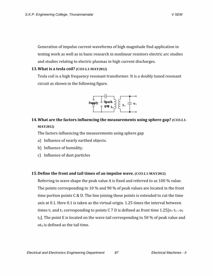
S.K.P. Engineering College, Tiruvannamalai V SEM
Electrical and Electronics Engineering Department 87 Electrical Machines - II
Generation of impulse current waveforms of high magnitude find application in
testing work as well as in basic research in nonlinear resistors electric arc studies
and studies relating to electric plasmas in high current discharges.
13. What is a tesla coil? (CO3-L1-MAY2012)
Tesla coil is a high frequency resonant transformer. It is a doubly tuned resonant
circuit as shown in the following figure.
14. What are the factors influencing the measurements using sphere gap? (CO3-L1-
MAY2012)
The factors influencing the measurements using sphere gap
a) Influence of nearly earthed objects.
b) Influence of humidity.
c) Influence of dust particles
15. Define the front and tail times of an impulse wave. (CO3-L1-MAY2012)
Referring to wave shape the peak value A is fixed and referred to as 100 % value.
The points corresponding to 10 % and 90 % of peak values are located in the front
time portion points C & D. The line joining these points is extended to cut the time
axis at 0.1. Here 0.1 is taken as the virtual origin. 1.25 times the interval between
times t1 and t1 corresponding to points C 7 D is defined as front time 1.25[o1 t1 = o2
t2]. The point E is located on the wave tail corresponding to 50 % of peak value and
ot4 is defined as the tail time.
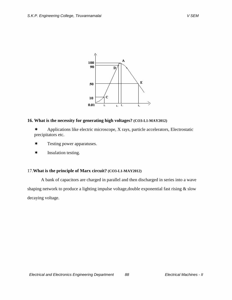
S.K.P. Engineering College, Tiruvannamalai V SEM
Electrical and Electronics Engineering Department 88 Electrical Machines - II
16. What is the necessity for generating high voltages? (CO3-L1-MAY2012)
Applications like electric microscope, X rays, particle accelerators, Electrostatic
precipitators etc.
Testing power apparatuses.
Insulation testing.
17.What is the principle of Marx circuit? (CO3-L1-MAY2012)
A bank of capacitors are charged in parallel and then discharged in series into a wave
shaping network to produce a lighting impulse voltage,double exponential fast rising & slow
decaying voltage.
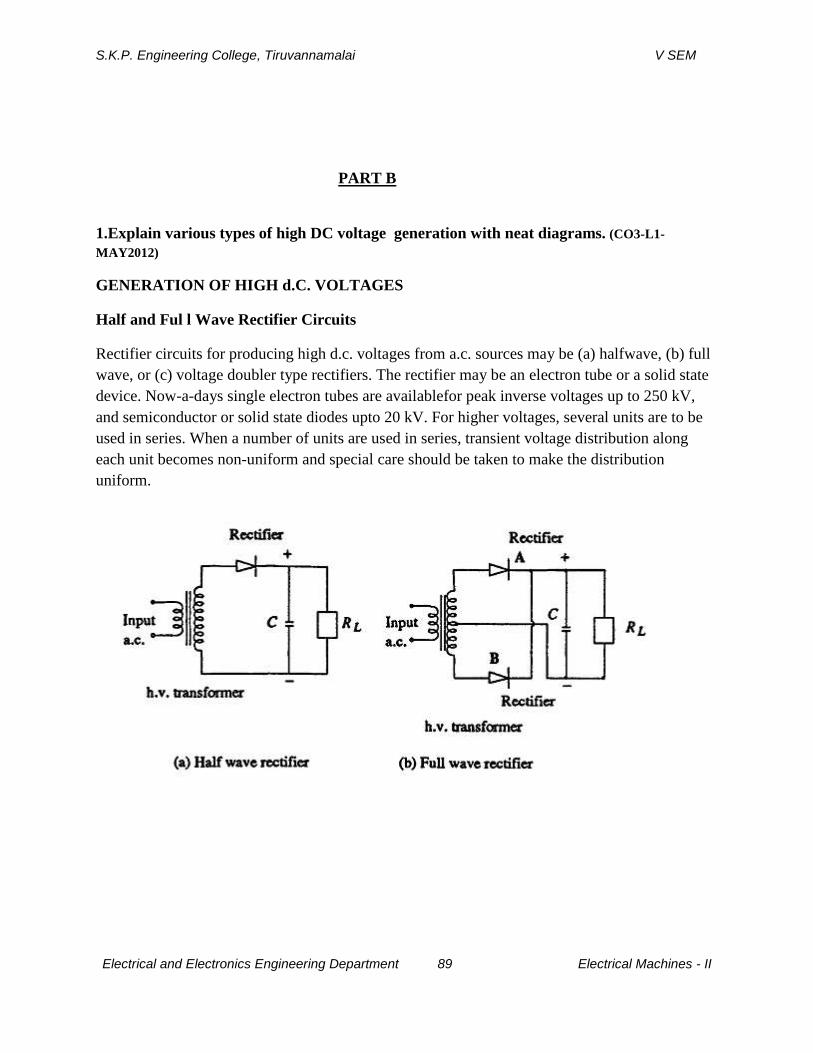
S.K.P. Engineering College, Tiruvannamalai V SEM
Electrical and Electronics Engineering Department 89 Electrical Machines - II
PART B
1.Explain various types of high DC voltage generation with neat diagrams. (CO3-L1-
MAY2012)
GENERATION OF HIGH d.C. VOLTAGES
Half and Ful l Wave Rectifier Circuits
Rectifier circuits for producing high d.c. voltages from a.c. sources may be (a) halfwave, (b) full
wave, or (c) voltage doubler type rectifiers. The rectifier may be an electron tube or a solid state
device. Now-a-days single electron tubes are availablefor peak inverse voltages up to 250 kV,
and semiconductor or solid state diodes upto 20 kV. For higher voltages, several units are to be
used in series. When a number of units are used in series, transient voltage distribution along
each unit becomes non-uniform and special care should be taken to make the distribution
uniform.
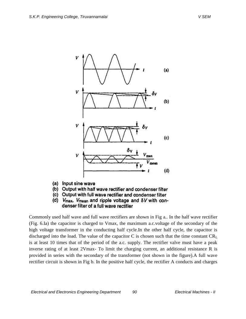
S.K.P. Engineering College, Tiruvannamalai V SEM
Electrical and Electronics Engineering Department 90 Electrical Machines - II
Commonly used half wave and full wave rectifiers are shown in Fig a.. In the half wave rectifier
(Fig. 6.Ia) the capacitor is charged to Vmax, the maximum a.c.voltage of the secondary of the
high voltage transformer in the conducting half cycle.In the other half cycle, the capacitor is
discharged into the load. The value of the capacitor C is chosen such that the time constant CRL
is at least 10 times that of the period of the a.c. supply. The rectifier valve must have a peak
inverse rating of at least 2Vmax- To limit the charging current, an additional resistance R is
provided in series with the secondary of the transformer (not shown in the figure).A full wave
rectifier circuit is shown in Fig b. In the positive half cycle, the rectifier A conducts and charges

S.K.P. Engineering College, Tiruvannamalai V SEM
Electrical and Electronics Engineering Department 91 Electrical Machines - II
the capacitor C, while in the negative half cycle the rectifier B conducts and charges the
capacitor. The source transformer requires a centre tapped secondary with a rating of 2V.For
applications at high voltages of 50 kV and above, the rectifier valves used are of special
construction. Apart from the filament, the cathode and the anode, they contain a protective shield
or grid around the filament and the cathode. The anode willbe usually a circular plate. Since the
electrostatic field gradients are quite large, theheater and the cathode experience large
electrostatic forces during the non-conduction periods. To protect the various elements from
these forces, the anode is firmly fixed to the valve cover on one side. On the other side, where
the cathode and filament are located, a steel mesh structure or a protective grid kept at the
cathode potential surrounds them so that the mechanical forces between the anode and
thecathode £re reflected on the grid structure only.In modern high voltage laboratories and
testing installations, semiconductor rectifier stacks are commonly used for producing d.c.
voltages. Semiconductor diodes are not true valves since they have finite but very small
conduction in the backward direction. The more commonly preferred diodes for high voltage
rectifiers are silicon diodes with peak inverse voltage (P.I.V.) of 1 kV to 2 kV. However, for
laboratory applications the current requirement is small (a few milliamperes, and less than one
ampere) and as such a selenium element stack with PJ.V. of up to 500 kV may be employed
without the use of any voltage grading capacitors.Both full wave and half wave rectifiers
produce d.c. voltages less than the a.c.maximum voltage. Also, ripple or the voltage fluctuation
will be present, and this has to be kept within a reasonable limit by means of filters.
Ripple Voltage with Half Wave and Full Wave Rectifiers
When a full wave or a half wave rectifier is used along with the smoothing condenser C, the
voltage on no load will be the maximum a.c. voltage. But when on load, the condenser gets
charged from the supply voltage and discharges into load resistance RI whenever the supply
voltage waveform varies from peak value to zero value.These waveforms are shown in Fig.
When loaded, a fluctuation in the output d.c.voltage 6V appears, and is called a ripple. The ripple
voltage SV is larger for a halfwave rectifier than that for a full wave rectifier, since the discharge
period in the case of half wave rectifier is larger as shown in Fig.. The ripple δV depends on (a)
the supply voltage frequency/, (b) the time constant CRLand (c) the reactance of the supply
transformer XL. For half wave rectifiers, the ripple frequency is equal to the supply frequency
and for full wave rectifiers, it is twice that value. The ripple voltageis to be kept as low as

S.K.P. Engineering College, Tiruvannamalai V SEM
Electrical and Electronics Engineering Department 92 Electrical Machines - II
possible with the proper choice of the filter condenser and the transformer reactance for a given
load RL.
2.Explain the working of voltage doubler circuit with diagrams. (CO3-L1-MAY2012)
Voltage Doubler Circuits:
Both full wave and half wave rectifier circuits produce a d.c. voltage less than the
a.c.maximum voltage. When higher d.c. voltages are needed, a voltage doubler or cascaded
rectifier doubler circuits are used. The schematic diagram of voltage doublers are given in
Figs.In voltage doubler circuit shown in Fig. 6.3a, the condenser C1 is charged through rectifier
R to a voltage of +Vmax with polarity as shown in the figure during the negative half cycle. As
the voltage of the transformer rises to positive Vmax during the next half cycle, the potential of
the other terminal of C\ rises to a voltage of +2Vmax.

S.K.P. Engineering College, Tiruvannamalai V SEM
Electrical and Electronics Engineering Department 93 Electrical Machines - II
Thus, the condenser C2 in turn is charged through R2 to 2Vmax. Normally the d.c.output voltage
on load will be less than 2Vmax, depending on the time constant C2and the forward charging
time constants. The ripple voltage of these circuits will be about 2% for RL< 10 and XLr< 0.25,
where X and r are the reactance and resistance of the input transformer. The rectifiers are rated to
a peak inverse voltage of 2Vmax,and the condensers C1and C1 must also have the same rating.
If the load current is large, the ripple also is more.Cascaded voltage doublers are used when
larger output voltages are needed without changing the input transformer voltage level. A typical
voltage doubler is shown in Fig and its input and output waveforms are shown in Fig. The
rectifiersR1 and R2 with transformer T1 and condensers C1 and C2 produce an outputvoltage of
2V in the same way as described above. This circuit is duplicated and connected in series or
cascade to obtain a further voltage doubling to 4V. T is an isolating transformer to give an
insulation for 2Kmax since the transformer T is at a potential of 2Vm above the ground. The
voltage distribution along the rectifier string R1, R2,R3 and R4 is made uniform by having
condensers C1, C2, C3 and C4 of equal values. The arrangement may be extended to give 6V,
8V, and so on by repeating further stages with suitable isolating transformers. In all the voltage
doubler circuits,if valves are used, the filament transformers have to be suitably designed and
insulated, as all the cathodes will not be at the same potential from ground. The arrangement
becomes cumbersome if more than 4V is needed with cascaded steps.
3.With a neat circuit explain the working principle of a Cockcroft Walton voltage
multiplier circuit. (CO3-L1-MAY2012)
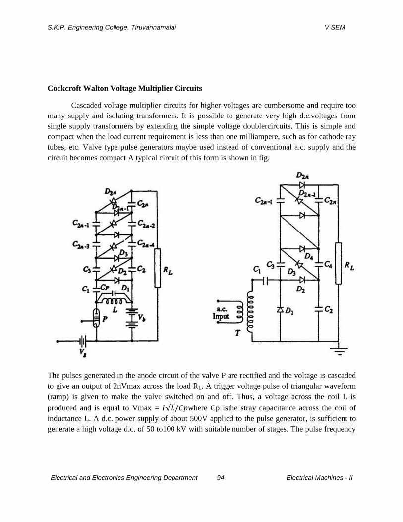
S.K.P. Engineering College, Tiruvannamalai V SEM
Electrical and Electronics Engineering Department 94 Electrical Machines - II
Cockcroft Walton Voltage Multiplier Circuits
Cascaded voltage multiplier circuits for higher voltages are cumbersome and require too
many supply and isolating transformers. It is possible to generate very high d.c.voltages from
single supply transformers by extending the simple voltage doublercircuits. This is simple and
compact when the load current requirement is less than one milliampere, such as for cathode ray
tubes, etc. Valve type pulse generators maybe used instead of conventional a.c. supply and the
circuit becomes compact A typical circuit of this form is shown in fig.
The pulses generated in the anode circuit of the valve P are rectified and the voltage is cascaded
to give an output of 2nVmax across the load RL. A trigger voltage pulse of triangular waveform
(ramp) is given to make the valve switched on and off. Thus, a voltage across the coil L is
produced and is equal to Vmax = where Cp isthe stray capacitance across the coil of
inductance L. A d.c. power supply of about 500V applied to the pulse generator, is sufficient to
generate a high voltage d.c. of 50 to100 kV with suitable number of stages. The pulse frequency
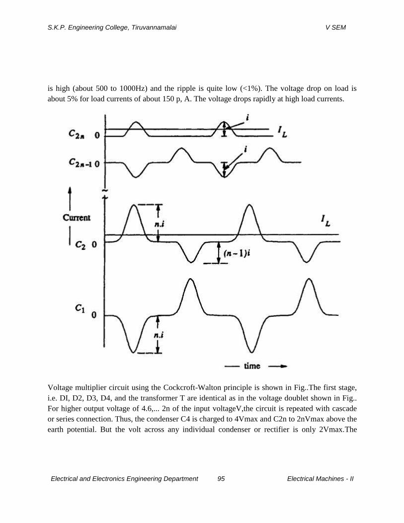
S.K.P. Engineering College, Tiruvannamalai V SEM
Electrical and Electronics Engineering Department 95 Electrical Machines - II
is high (about 500 to 1000Hz) and the ripple is quite low (<1%). The voltage drop on load is
about 5% for load currents of about 150 p, A. The voltage drops rapidly at high load currents.
Voltage multiplier circuit using the Cockcroft-Walton principle is shown in Fig..The first stage,
i.e. DI, D2, D3, D4, and the transformer T are identical as in the voltage doublet shown in Fig..
For higher output voltage of 4.6,... 2n of the input voltageV,the circuit is repeated with cascade
or series connection. Thus, the condenser C4 is charged to 4Vmax and C2n to 2nVmax above the
earth potential. But the volt across any individual condenser or rectifier is only 2Vmax.The

S.K.P. Engineering College, Tiruvannamalai V SEM
Electrical and Electronics Engineering Department 96 Electrical Machines - II
rectifiers D1, D3, ...D2n-1 shown in Fig. operate and conduct during the positive half cycles
while the rectifiers D2, D4... D2n conduct during the negative half cycles. Typical current and
voltage waveforms of such a circuit are shown in Figs. and respectively. The voltage on C2 is
the sum of the input a.c. voltage,Vac and the voltage across condenser C1,V1) as shown in Fig .
The mean voltage on C2 is less than the positive peak charging voltage (Vac + Vc1). The
voltages across other condensers C2 to C2n can be derived in the same manner, (i.e.) from the
difference between voltage across the previous condenser and the charging voltage.Finally the
voltage after 2n stages will be Vac (n1 + n2 + ...), where n1, n2,... are factors when ripple and
regulation are considered in the next rectifier. The ripplevoltage 5V and the voltage drop V in a
cascaded voltage multiplier unit are shownin Fig.
4.With a neat circuit explain the working principle of a Deltatron circuit. (CO3-L1-MAY2012)
Cascaded Modular Voltage Multipliers or "Deltatron" Circuits for Very High Voltages
A combination of Cockcroft-Walton type voltage multiplier with cascaded transformer d.c.
rectifier is developed recently for very high voltages but limited output currents having high
stability, small ripple factor and fast regulation. One such unit is recently patented by "ENGE" in
U.S.A., called "ENGETRON" or"DELTATRON". The schematic diagram of a typical Deltatron
unit is shown inFig.
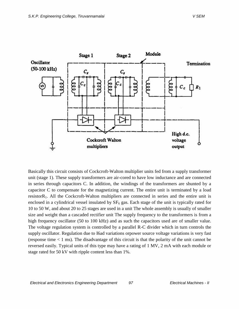
S.K.P. Engineering College, Tiruvannamalai V SEM
Electrical and Electronics Engineering Department 97 Electrical Machines - II
Basically this circuit consists of Cockcroft-Walton multiplier units fed from a supply transformer
unit (stage 1). These supply transformers are air-cored to have low inductance and are connected
in series through capacitors C. In addition, the windings of the transformers are shunted by a
capacitor C to compensate for the magnetizing current. The entire unit is terminated by a load
resistorR1. All the Cockcroft-Walton multipliers are connected in series and the entire unit is
enclosed in a cylindrical vessel insulated by SF6 gas. Each stage of the unit is typically rated for
10 to 50 W, and about 20 to 25 stages are used in a unit The whole assembly is usually of smaller
size and weight than a cascaded rectifier unit The supply frequency to the transformers is from a
high frequency oscillator (50 to 100 kHz) and as such the capacitors used are of smaller value.
The voltage regulation system is controlled by a parallel R-C divider which in turn controls the
supply oscillator. Regulation due to I6ad variations orpower source voltage variations is very fast
(response time < 1 ms). The disadvantage of this circuit is that the polarity of the unit cannot be
reversed easily. Typical units of this type may have a rating of 1 MV, 2 mA with each module or
stage rated for 50 kV with ripple content less than 1%.
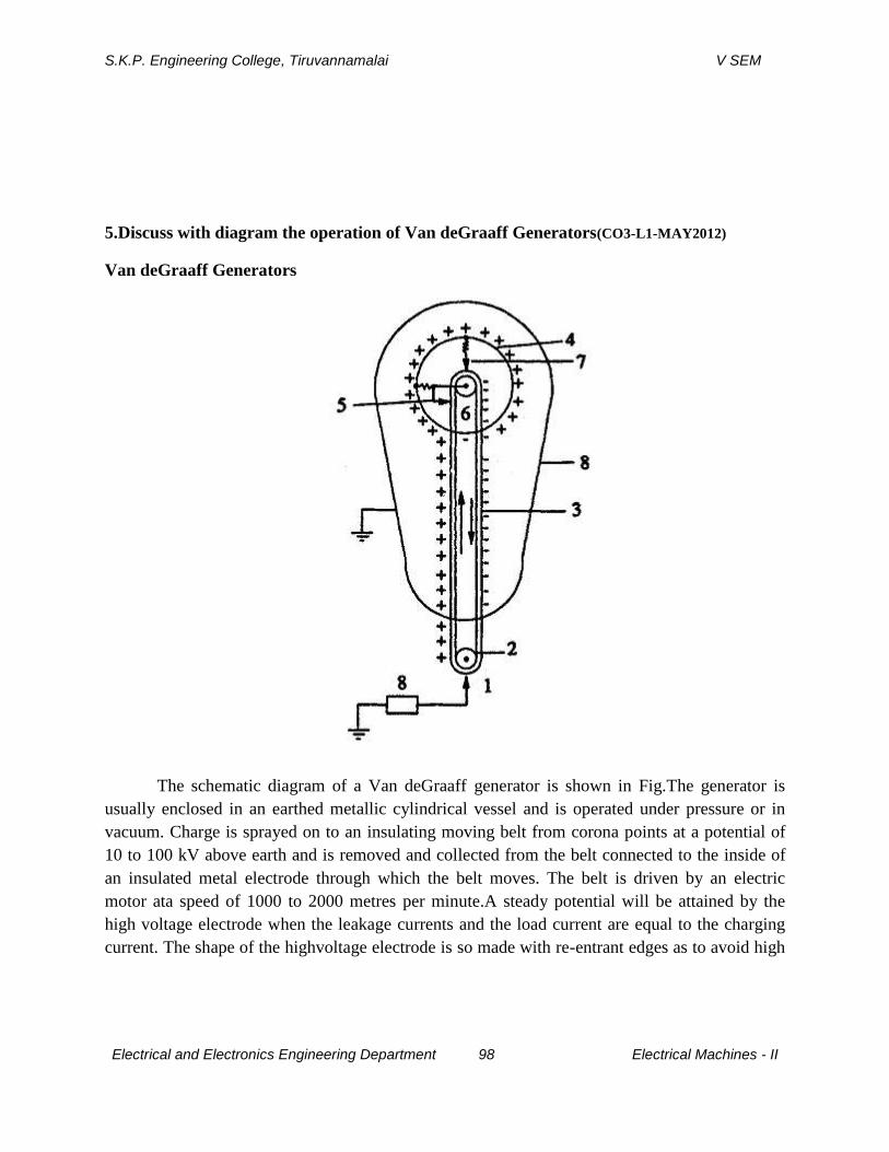
S.K.P. Engineering College, Tiruvannamalai V SEM
Electrical and Electronics Engineering Department 98 Electrical Machines - II
5.Discuss with diagram the operation of Van deGraaff Generators(CO3-L1-MAY2012)
Van deGraaff Generators
The schematic diagram of a Van deGraaff generator is shown in Fig.The generator is
usually enclosed in an earthed metallic cylindrical vessel and is operated under pressure or in
vacuum. Charge is sprayed on to an insulating moving belt from corona points at a potential of
10 to 100 kV above earth and is removed and collected from the belt connected to the inside of
an insulated metal electrode through which the belt moves. The belt is driven by an electric
motor ata speed of 1000 to 2000 metres per minute.A steady potential will be attained by the
high voltage electrode when the leakage currents and the load current are equal to the charging
current. The shape of the highvoltage electrode is so made with re-entrant edges as to avoid high
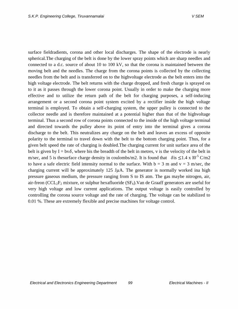
S.K.P. Engineering College, Tiruvannamalai V SEM
Electrical and Electronics Engineering Department 99 Electrical Machines - II
surface fieldradients, corona and other local discharges. The shape of the electrode is nearly
spherical.The charging of the belt is done by the lower spray points which are sharp needles and
connected to a d.c. source of about 10 to 100 kV, so that the corona is maintained between the
moving belt and the needles. The charge from the corona points is collected by the collecting
needles from the belt and is transferred on to the highvoltage electrode as the belt enters into the
high voltage electrode. The belt returns with the charge dropped, and fresh charge is sprayed on
to it as it passes through the lower corona point. Usually in order to make the charging more
effective and to utilize the return path of the belt for charging purposes, a self-inducing
arrangement or a second corona point system excited by a rectifier inside the high voltage
terminal is employed. To obtain a self-charging system, the upper pulley is connected to the
collector needle and is therefore maintained at a potential higher than that of the highvoltage
terminal. Thus a second row of corona points connected to the inside of the high voltage terminal
and directed towards the pulley above its point of entry into the terminal gives a corona
discharge to the belt. This neutralizes any charge on the belt and leaves an excess of opposite
polarity to the terminal to travel down with the belt to the bottom charging point. Thus, for a
given belt speed the rate of charging is doubled.The charging current for unit surface area of the
belt is given by I = bv , where bis the breadth of the belt in metres, v is the velocity of the belt in
m/sec, and 5 is thesurface charge density in coulombs/m2. It is found that is 1.4 x I0-5
C/m2
to have a safe electric field intensity normal to the surface. With b = 3 m and v = 3 m/sec, the
charging current will be approximately 125 J A. The generator is normally worked ina high
pressure gaseous medium, the pressure ranging from S to IS atm. The gas maybe nitrogen, air,
air-freon (CCL2F2 mixture, or sulphur hexafluoride (SF6).Van de Graaff generators are useful for
very high voltage and low current applications. The output voltage is easily controlled by
controlling the corona source voltage and the rate of charging. The voltage can be stabilized to
0.01 %. These are extremely flexible and precise machines for voltage control.
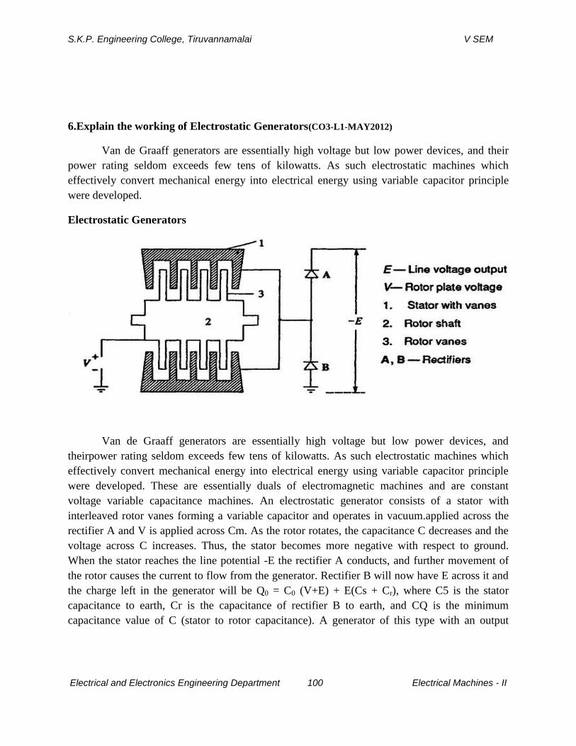
S.K.P. Engineering College, Tiruvannamalai V SEM
Electrical and Electronics Engineering Department 100 Electrical Machines - II
6.Explain the working of Electrostatic Generators(CO3-L1-MAY2012)
Van de Graaff generators are essentially high voltage but low power devices, and their
power rating seldom exceeds few tens of kilowatts. As such electrostatic machines which
effectively convert mechanical energy into electrical energy using variable capacitor principle
were developed.
Electrostatic Generators
Van de Graaff generators are essentially high voltage but low power devices, and
theirpower rating seldom exceeds few tens of kilowatts. As such electrostatic machines which
effectively convert mechanical energy into electrical energy using variable capacitor principle
were developed. These are essentially duals of electromagnetic machines and are constant
voltage variable capacitance machines. An electrostatic generator consists of a stator with
interleaved rotor vanes forming a variable capacitor and operates in vacuum.applied across the
rectifier A and V is applied across Cm. As the rotor rotates, the capacitance C decreases and the
voltage across C increases. Thus, the stator becomes more negative with respect to ground.
When the stator reaches the line potential -E the rectifier A conducts, and further movement of
the rotor causes the current to flow from the generator. Rectifier B will now have E across it and
the charge left in the generator will be Q0 = C0 (V+E) + E(Cs + Cr), where C5 is the stator
capacitance to earth, Cr is the capacitance of rectifier B to earth, and CQ is the minimum
capacitance value of C (stator to rotor capacitance). A generator of this type with an output
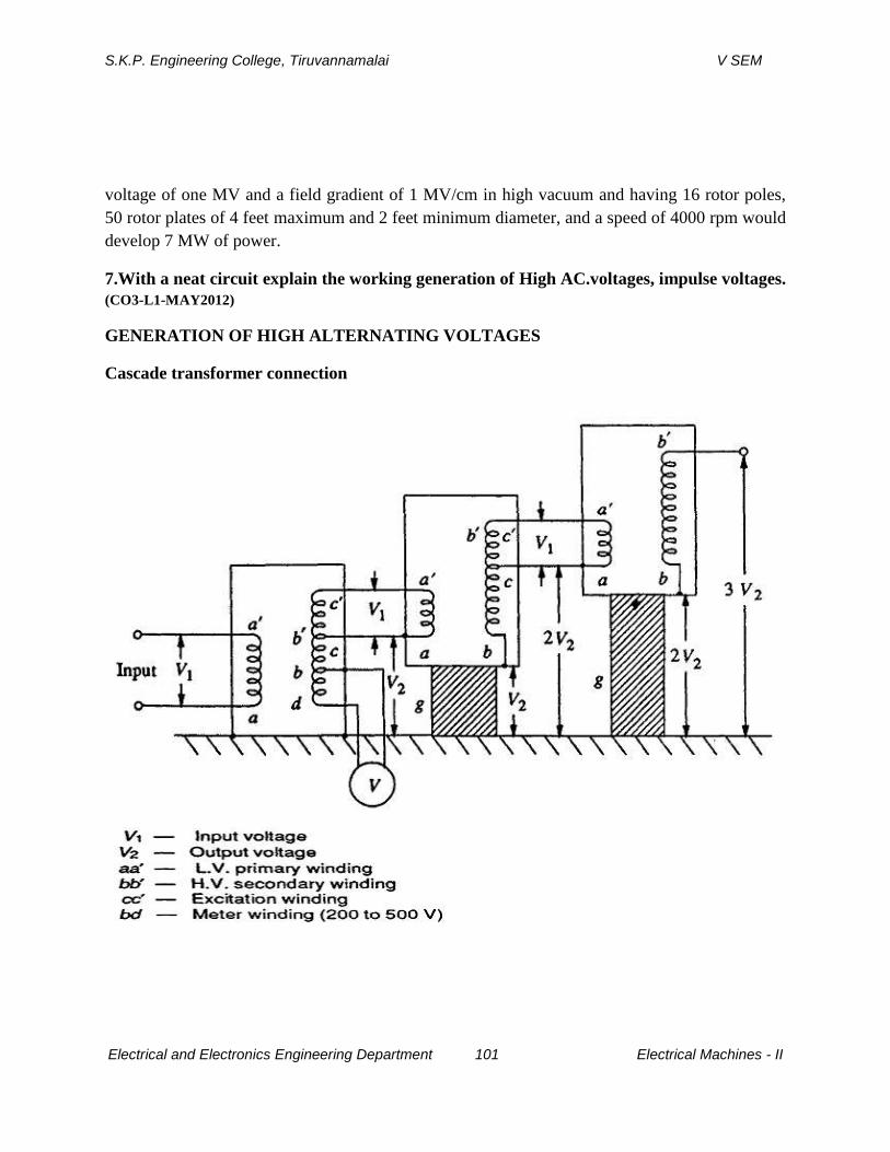
S.K.P. Engineering College, Tiruvannamalai V SEM
Electrical and Electronics Engineering Department 101 Electrical Machines - II
voltage of one MV and a field gradient of 1 MV/cm in high vacuum and having 16 rotor poles,
50 rotor plates of 4 feet maximum and 2 feet minimum diameter, and a speed of 4000 rpm would
develop 7 MW of power.
7.With a neat circuit explain the working generation of High AC.voltages, impulse voltages.
(CO3-L1-MAY2012)
GENERATION OF HIGH ALTERNATING VOLTAGES
Cascade transformer connection

S.K.P. Engineering College, Tiruvannamalai V SEM
Electrical and Electronics Engineering Department 102 Electrical Machines - II
When test voltage requirements are less than about 300 kV, a single transformer can be
used for test purposes. The impedance of the transformer should be generally less than 5% and
must be capable of giving the short circuit current for one minute or more depending on the
design. In addition to the normal windings, namely, the low and highvoltage windings, a third
winding known as meter winding is provided to measure the output voltage. For higher voltage
requirements, a single unit construction becomes difficult and costly due to insulation problems.
Moreover, transportation and erection of large transformers become difficult. These drawbacks
are overcome by series connection or cascading of the several identical units of transformers,
wherein the high voltage windings of all the units effectively come in series.
Resonant Transformers
The equivalent circuit of a high voltage testing transformer consists of the leakage
reactances of the windings, the winding resistances, the magnetizing reactance, and the shunt
capacitance across the output terminal due to the bushing of the high voltage terminal and also
that of the test object. This is shown in Fig. with its equivalent circuit in Fig. . It may be seen that
it is possible to have series resonance at power frequency O), if (L1 +L2)=1µf. With this
condition, the current in the test object is very large and is limited only by the resistance of the
circuit. The waveform of the voltage across the test object will be purely sinusoidal. The
magnitude of the voltage across the capacitance C of the test object will be
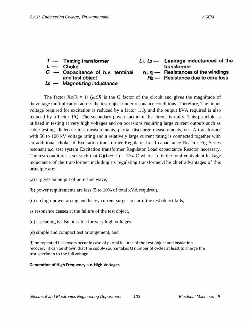
S.K.P. Engineering College, Tiruvannamalai V SEM
Electrical and Electronics Engineering Department 103 Electrical Machines - II
The factor Xc/R = 1/ ( is the Q factor of the circuit and gives the magnitude of
thevoltage multiplication across the test object under resonance conditions. Therefore, The input
voltage required for excitation is reduced by a factor 1/Q, and the output kVA required is also
reduced by a factor 1/Q. The secondary power factor of the circuit is unity. This principle is
utilized in testing at very high voltages and on occasions requiring large current outputs such as
cable testing, dielectric loss measurements, partial discharge measurements, etc. A transformer
with 50 to 100 kV voltage rating and a relatively large current rating is connected together with
an additional choke, if Excitation transformer Regulator Load capacitance Reactor Fig Series
resonant a.c. test system Excitation transformer Regulator Load capacitance Reactor necessary.
The test condition is set such that G)(Le+ L) = 1/c C where Le is the total equivalent leakage
inductance of the transformer including its regulating transformer.The chief advantages of this
principle are:
(a) it gives an output of pure sine wave,
(b) power requirements are less (5 to 10% of total kVA required),
(c) no high-power arcing and heavy current surges occur if the test object fails,
as resonance ceases at the failure of the test object,
(d) cascading is also possible for very high voltages,
(e) simple and compact test arrangement, and
(f) no repeated flashovers occur in case of partial failures of the test object and insulation recovery. It can be shown that the supply source takes Q number of cycles at least to charge the test specimen to the full voltage. Generation of High Frequency a.c. High Voltages
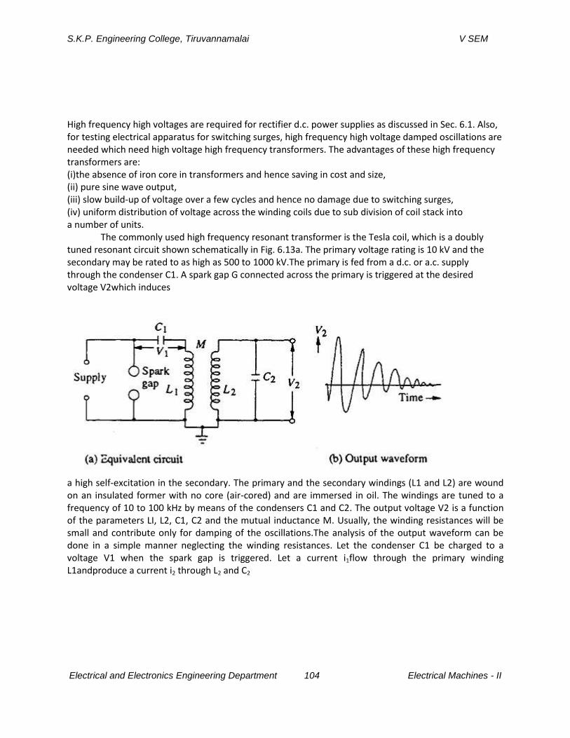
S.K.P. Engineering College, Tiruvannamalai V SEM
Electrical and Electronics Engineering Department 104 Electrical Machines - II
High frequency high voltages are required for rectifier d.c. power supplies as discussed in Sec. 6.1. Also, for testing electrical apparatus for switching surges, high frequency high voltage damped oscillations are needed which need high voltage high frequency transformers. The advantages of these high frequency transformers are: (i)the absence of iron core in transformers and hence saving in cost and size, (ii) pure sine wave output, (iii) slow build-up of voltage over a few cycles and hence no damage due to switching surges, (iv) uniform distribution of voltage across the winding coils due to sub division of coil stack into a number of units.
The commonly used high frequency resonant transformer is the Tesla coil, which is a doubly tuned resonant circuit shown schematically in Fig. 6.13a. The primary voltage rating is 10 kV and the secondary may be rated to as high as 500 to 1000 kV.The primary is fed from a d.c. or a.c. supply through the condenser C1. A spark gap G connected across the primary is triggered at the desired voltage V2which induces
a high self-excitation in the secondary. The primary and the secondary windings (L1 and L2) are wound on an insulated former with no core (air-cored) and are immersed in oil. The windings are tuned to a frequency of 10 to 100 kHz by means of the condensers C1 and C2. The output voltage V2 is a function of the parameters LI, L2, C1, C2 and the mutual inductance M. Usually, the winding resistances will be small and contribute only for damping of the oscillations.The analysis of the output waveform can be done in a simple manner neglecting the winding resistances. Let the condenser C1 be charged to a voltage V1 when the spark gap is triggered. Let a current i1flow through the primary winding L1andproduce a current i2 through L2 and C2
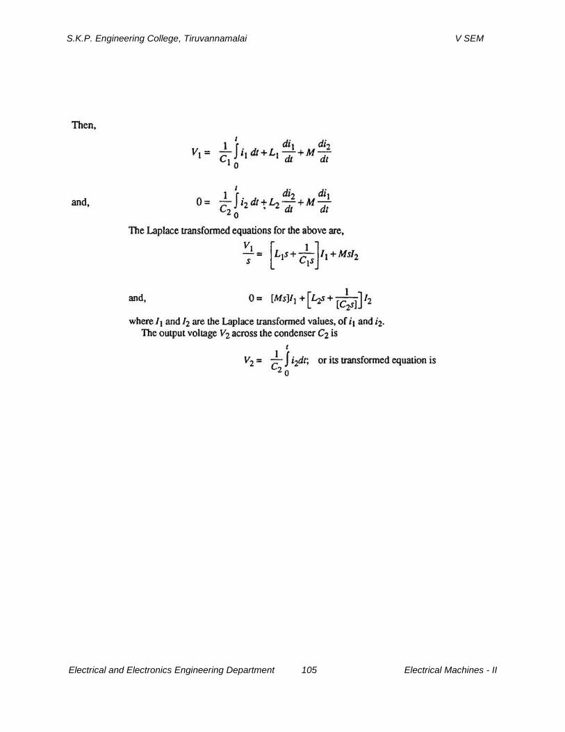
S.K.P. Engineering College, Tiruvannamalai V SEM
Electrical and Electronics Engineering Department 105 Electrical Machines - II
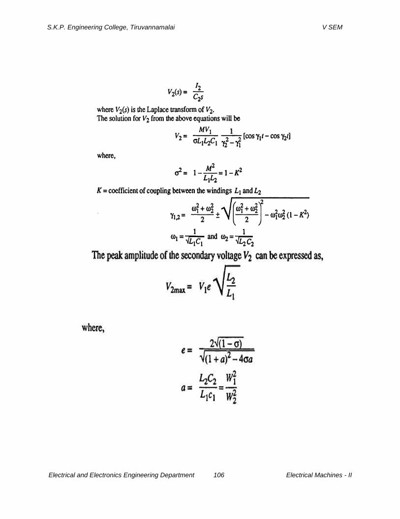
S.K.P. Engineering College, Tiruvannamalai V SEM
Electrical and Electronics Engineering Department 106 Electrical Machines - II

S.K.P. Engineering College, Tiruvannamalai V SEM
Electrical and Electronics Engineering Department 107 Electrical Machines - II
A more simplified analysis for the Tesla coil may be presented by considering that the energy stored in the primary circuit in the capacitance C1 is transferred to C2 via the magnetic coupling. If W1 is the energy stored in C1 and W2 is the energy transferred to C2 and if the efficiency of the transformer is , then
It can be shown that if the coefficient of coupling K is large the oscillation frequency is less, and for large values of the winding resistances and K, the waveform may become a unidirectional impulse. This is shown in the next sections while dealing with the generation of switching surges GENERATION OF IMPULSE VOLTAGES Standard Impulse Waveshapes Transient overvoltages due to lightning and switching surges cause steep build-up ofvoltage on transmission lines and other electrical apparatus. Experimental investigations showed that these waves have a rise time of 0.5 to. 10 Ji s and decay time to 50%of the peak value of the order of 30 to 200 \i s. The waveshapes are arbitrary, but mostly unidirectional. It is shown that lightning overvoltage wave can be representedas double exponential waves defined by the equation
where and are constants of microsecond values. The above equation represents a unidirectional wave which usually has a rapid rise to the peak value and slowly falls to zero value. The general waveshape is given in Fig. Impulse waves are specified by defining their rise or front time, fall or tailtime to 50% peak value, and the value of the peak voltage. Thus 1.2/50 s, 1000 kVwave represents an impulse voltage wave with a front time of 1.2 (is, fall time to 50% peak value of 50 s, and a peak value of 1000 kV. When impulse waveshapes arerecorded, the initial portion of the wave will not be clearly defined or sometimes willbe missing. Moreover, due to disturbances it may contain superimposed oscillationsin the rising portion. Hence, the front and tail times have to be defined.Referring to the waveshape in Fig. 6.14, the peak value A is fixed and referred to as 100% value. The points corresponding to 10% and 90% of the peak values are located in the front portion (points C and D). The line joining these points is extended to cut the time axis at 01. 01 is taken as
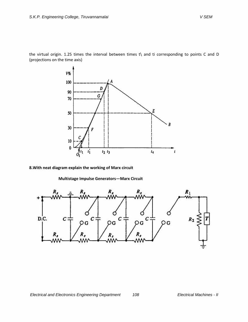
S.K.P. Engineering College, Tiruvannamalai V SEM
Electrical and Electronics Engineering Department 108 Electrical Machines - II
the virtual origin. 1.25 times the interval between times t\ and ti corresponding to points C and D (projections on the time axis)
8.With neat diagram explain the working of Marx circuit
Multistage Impulse Generators—Marx Circuit
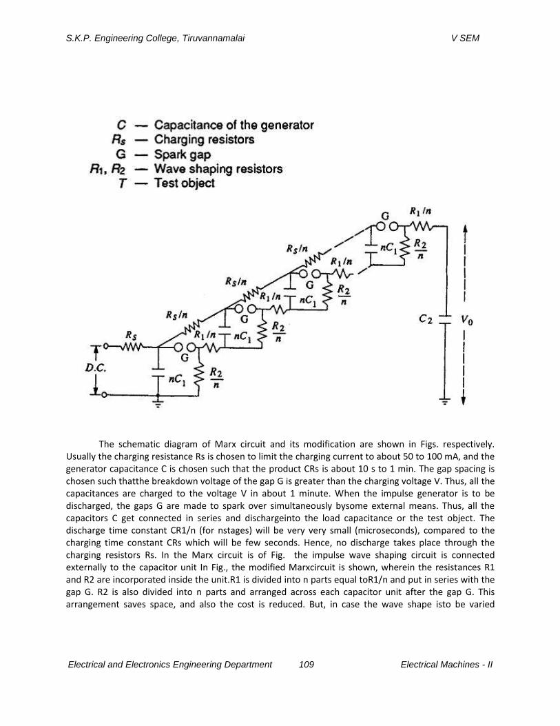
S.K.P. Engineering College, Tiruvannamalai V SEM
Electrical and Electronics Engineering Department 109 Electrical Machines - II
The schematic diagram of Marx circuit and its modification are shown in Figs. respectively. Usually the charging resistance Rs is chosen to limit the charging current to about 50 to 100 mA, and the generator capacitance C is chosen such that the product CRs is about 10 s to 1 min. The gap spacing is chosen such thatthe breakdown voltage of the gap G is greater than the charging voltage V. Thus, all the capacitances are charged to the voltage V in about 1 minute. When the impulse generator is to be discharged, the gaps G are made to spark over simultaneously bysome external means. Thus, all the capacitors C get connected in series and dischargeinto the load capacitance or the test object. The discharge time constant CR1/n (for nstages) will be very very small (microseconds), compared to the charging time constant CRs which will be few seconds. Hence, no discharge takes place through the charging resistors Rs. In the Marx circuit is of Fig. the impulse wave shaping circuit is connected externally to the capacitor unit In Fig., the modified Marxcircuit is shown, wherein the resistances R1 and R2 are incorporated inside the unit.R1 is divided into n parts equal toR1/n and put in series with the gap G. R2 is also divided into n parts and arranged across each capacitor unit after the gap G. This arrangement saves space, and also the cost is reduced. But, in case the wave shape isto be varied
S.K.P. Engineering College, Tiruvannamalai V SEM
Electrical and Electronics Engineering Department 110 Electrical Machines - II
widely, the variation becomes difficult. The additional advantages gained by distributing R1 and R2 inside the unit are that the control resistors are smaller in size and the efficiency (Vo/nv) is high. Impulse generators are nominally rated by the total voltage (nominal), the number of stages, and the gross energy stored. The nominal output voltage is the number ofstages multiplied by the charging voltage. The nominal energy stored is given by–1/2C1V
2 where C1 = C1/n (the discharge capacitance) and V is the nominal maximum voltage (n times charging voltage). A 16-stage impulse generator having a stagecapacitance of 0.280 F and a maximum charging voltage of 300 kV will have anenergy rating of 192 kW sec. The height of the generator will be about 15 m and willoccupy a floor area of about 3.25 x 3.00 m. The waveform of either polarity can be obtained by suitably changing the charging unit polarity. Components of a Multistage Impulse Generator (i) D.C. Charging Set The charging unit should be capable of giving a variable d.c. voltage of either polarity to charge the generator capacitors to the required value. (ii) Charging Resistors
These will be non-inductive high value resistors of about 10 to 100 kilo-ohms. Each resistor will be designed to have a maximum voltage between 50 and 100 kV. (iii) Generator Capacitors and Spark Gaps
These are arranged vertically one over the other with all the spark gaps aligned. The capacitors are designed for several charging and discharging operations. On dead short circuit, the capacitors will be capable of giving 10 kA of current. The spark gaps will be usually spheres or hemispheres of 10 to 25 cm diameter. Sometimes spherical ended cylinders with a central support may also be used. (iv) Wave-shaping Resistors and Capacitors
Resistors will be non-inductive wound type and should be capable of discharging impulse currents of 1000 A or more. Each resistor will be designed for a maximum voltage of 50 to 100 kV. The resistances are bifilar wound or non-inductive thin flat insulating sheets. In some cases, they are wound on thin cylindrical formers and are completely enclosed. The load capacitor may be of compressed gas or oil filled with a capacitance of 1 to 10 Modern impulse generators have their wave-shaping resistors included internallywith a flexibility to add additional resistors outside, when the generator capacitance is changed (with series parallel connection to get the desired energy rating at a given test voltage). Such generators optimize the set of resistors. A commercial impulse voltage generator uses six sets of resistors ranging from 1.0 ohm to about 160 ohms with different combinations (with a maximum of two resistors at a time) such that a resistance value varying from 0.7 ohm to 235 ohms per stage is obtained, covering a very large range of energy and test voltages. The resistors used are usually resin cast with voltage and energy ratings of 200 to 250 kV and 2.0 to 5.0 kWsec. The entire range of lightning and switching impulse voltages can be covered using these resistors either in series or in parallel combination. (v) Triggering System
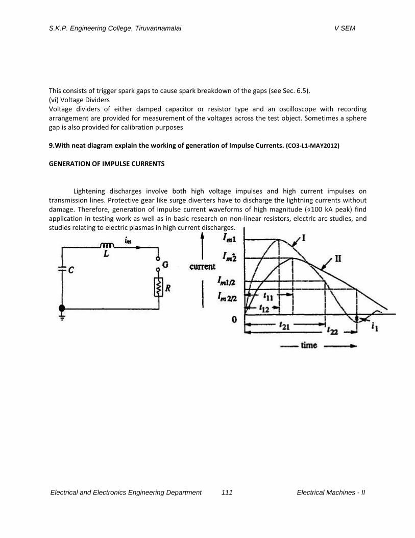
S.K.P. Engineering College, Tiruvannamalai V SEM
Electrical and Electronics Engineering Department 111 Electrical Machines - II
This consists of trigger spark gaps to cause spark breakdown of the gaps (see Sec. 6.5). (vi) Voltage Dividers Voltage dividers of either damped capacitor or resistor type and an oscilloscope with recording arrangement are provided for measurement of the voltages across the test object. Sometimes a sphere gap is also provided for calibration purposes 9.With neat diagram explain the working of generation of Impulse Currents. (CO3-L1-MAY2012) GENERATION OF IMPULSE CURRENTS
Lightening discharges involve both high voltage impulses and high current impulses on transmission lines. Protective gear like surge diverters have to discharge the lightning currents without damage. Therefore, generation of impulse current waveforms of high magnitude («100 kA peak) find application in testing work as well as in basic research on non-linear resistors, electric arc studies, and studies relating to electric plasmas in high current discharges.
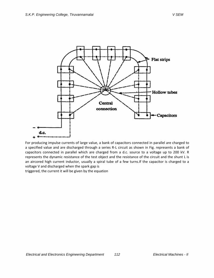
S.K.P. Engineering College, Tiruvannamalai V SEM
Electrical and Electronics Engineering Department 112 Electrical Machines - II
For producing impulse currents of large value, a bank of capacitors connected in parallel are charged to a specified value and are discharged through a series R-L circuit as shown in Fig. represents a bank of capacitors connected in parallel which are charged from a d.c. source to a voltage up to 200 kV. R represents the dynamic resistance of the test object and the resistance of the circuit and the shunt L is an aircored high current inductor, usually a spiral tube of a few turns.If the capacitor is charged to a voltage V and discharged when the spark gap is triggered, the current it will be given by the equation
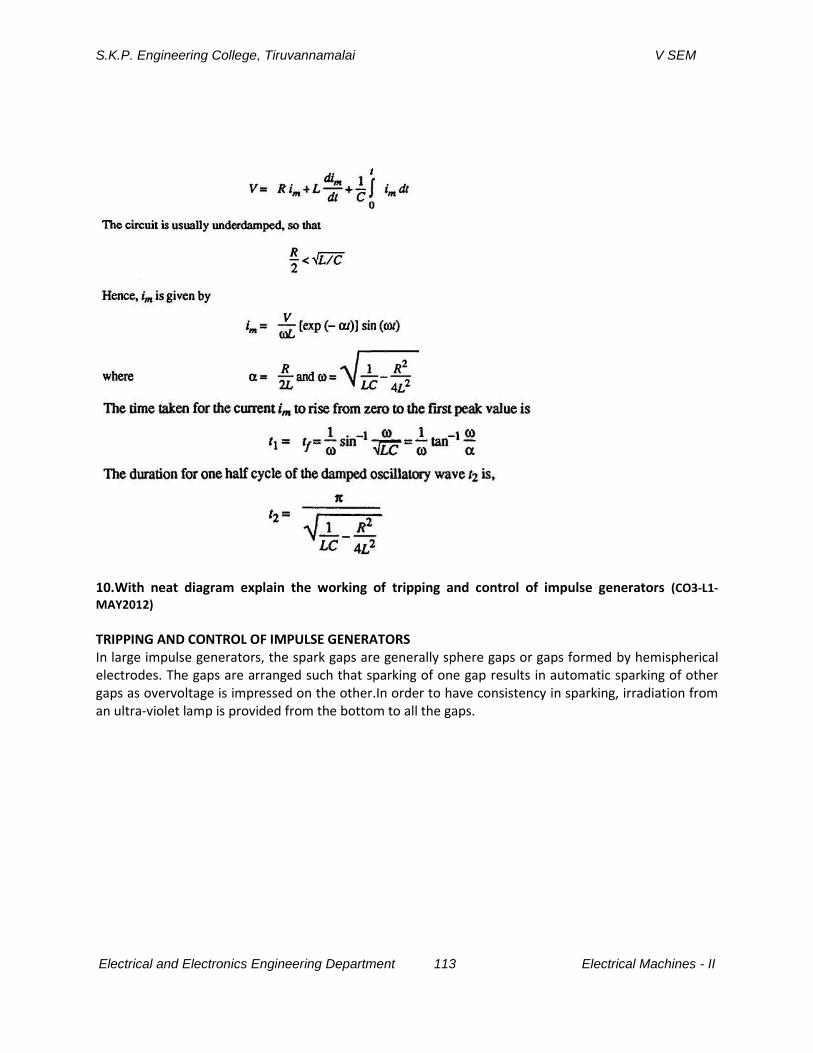
S.K.P. Engineering College, Tiruvannamalai V SEM
Electrical and Electronics Engineering Department 113 Electrical Machines - II
10.With neat diagram explain the working of tripping and control of impulse generators (CO3-L1-
MAY2012) TRIPPING AND CONTROL OF IMPULSE GENERATORS In large impulse generators, the spark gaps are generally sphere gaps or gaps formed by hemispherical electrodes. The gaps are arranged such that sparking of one gap results in automatic sparking of other gaps as overvoltage is impressed on the other.In order to have consistency in sparking, irradiation from an ultra-violet lamp is provided from the bottom to all the gaps.
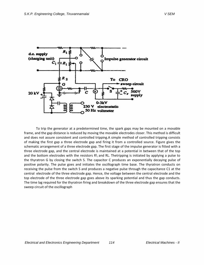
S.K.P. Engineering College, Tiruvannamalai V SEM
Electrical and Electronics Engineering Department 114 Electrical Machines - II
To trip the generator at a predetermined time, the spark gaps may be mounted on a movable
frame, and the gap distance is reduced by moving the movable electrodes closer. This method is difficult and does not assure consistent and controlled tripping.A simple method of controlled tripping consists of making the first gap a three electrode gap and firing it from a controlled source. Figure gives the schematic arrangement of a three electrode gap. The first stage of the impulse generator is fitted with a three electrode gap, and the central electrode is maintained at a potential in between that of the top and the bottom electrodes with the resistors R\ and RL. Thetripping is initiated by applying a pulse to the thyratron G by closing the switch S. The capacitor C produces an exponentially decaying pulse of positive polarity. The pulse goes and initiates the oscillograph time base. The thyratron conducts on receiving the pulse from the switch S and produces a negative pulse through the capacitance C1 at the central electrode of the three electrode gap. Hence, the voltage between the central electrode and the top electrode of the three electrode gap goes above its sparking potential and thus the gap conducts. The time lag required for the thyratron firing and breakdown of the three electrode gap ensures that the sweep circuit of the oscillograph

S.K.P. Engineering College, Tiruvannamalai V SEM
Electrical and Electronics Engineering Department 115 Electrical Machines - II
coupling of voltage oscillations produced at the spark gap entering the oscilloscope through the
common trip circuit.The three electrode gap requires larger space and an elaborate construction. Now-a-days a trigatron gap shown in Fig. is used, and this requires much smaller voltage for operation compared to the three electrode gap. A trigatron gap consists of a high voltage spherical electrode of suitable size, an earthed main electrode of spherical shape, and a trigger electrode through the main electrode. The triggere electrode is a metal rod with an annular clearance of about 1 mm fitted into the main electrode through a bushing. The trigatron is connected to a pulse circuit as shown in Fig.b. Tripping of the impulse generator is effected by a trip pulse which produces a spark between the trigger electrode and the earthed sphere. Due to space charge effects and distortion of the field in the main gap, sparkover of the main gap Three Electrode Gap for Impulse Current Generator In the case of impulse current generators using three electrode gaps for tripping and control, a certain special design is needed. The electrodes have to carry high current from the capacitor bank. Secondly, the electrode has to switch large currents in a small duration of time (in about a microsecond). Therefore, the switch should have very low inductance. The erosion rate of the electrodes should be low.For high current capacitor banks, a number of spark gap switches connected in parallel as shown in Fig. are often used to meet the requirement. Recently,trigatron gaps are being replaced by triggered vacuum gaps, the advantage of the latter being fast switching at high currents (> 100 kA) in a few nanoseconds. Triggering of the spark gaps by focused laser beams is also adopted since the performance is better than the conventional triggering methods.
S.K.P. Engineering College, Tiruvannamalai V SEM
Electrical and Electronics Engineering Department 116 Electrical Machines - II
UNIT IV
MEASUREMENT OF HIGH VOLTAGES AND HIGH CURRENTS
PART A
1. What are the general methods used for measurement of high frequency and
impulse currents? (CO4-L1-MAY2011)
The following methods used for measurement of high frequency and impulse
currents
a) Potential divider with a cathode ray oscilloscope.
b) Peak voltmeters.
c) Sphere gaps
2. What is the high voltage d.c measurement techniques used? (CO4-L1-MAY2011)
The following techniques are used for measurement of high voltage dc.
a) Series resistance micro ammeter
b) Resistance potential-divider
c) Generating voltmeter
d) Sphere and other spark gaps
3. For what measurement are Hall generators normally used? (CO4-L1-MAY2011)
These are used for measurement of high direct currents. It can be used for
measurement of unidirectional a.c impulse current also.
4. What type of measuring devices are preferred for measurement of Impulse
currents of short duration? (CO4-L1-MAY2011)
Park’s tubular shunt (or) coaxial tube is preferred for measurement of impulse
current of short duration.
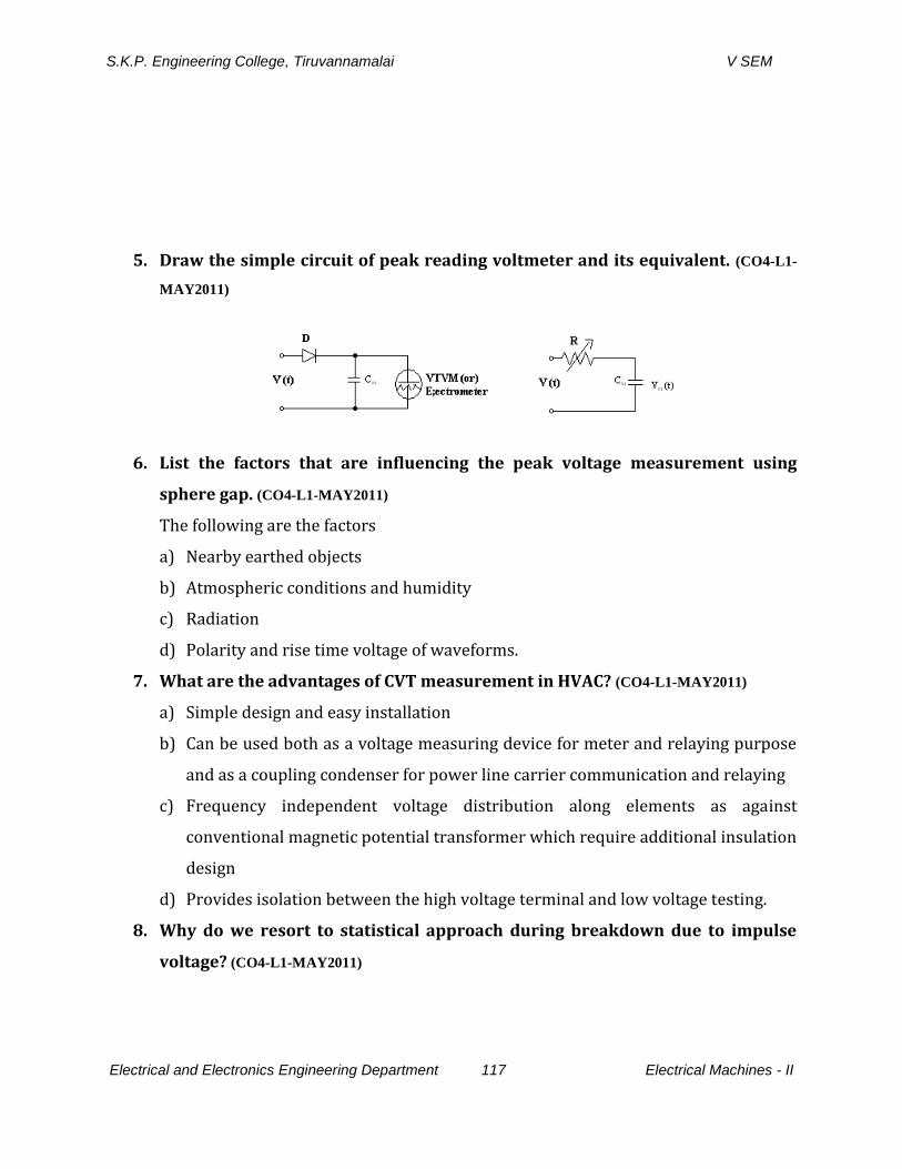
S.K.P. Engineering College, Tiruvannamalai V SEM
Electrical and Electronics Engineering Department 117 Electrical Machines - II
5. Draw the simple circuit of peak reading voltmeter and its equivalent. (CO4-L1-
MAY2011)
6. List the factors that are influencing the peak voltage measurement using
sphere gap. (CO4-L1-MAY2011)
The following are the factors
a) Nearby earthed objects
b) Atmospheric conditions and humidity
c) Radiation
d) Polarity and rise time voltage of waveforms.
7. What are the advantages of CVT measurement in HVAC? (CO4-L1-MAY2011)
a) Simple design and easy installation
b) Can be used both as a voltage measuring device for meter and relaying purpose
and as a coupling condenser for power line carrier communication and relaying
c) Frequency independent voltage distribution along elements as against
conventional magnetic potential transformer which require additional insulation
design
d) Provides isolation between the high voltage terminal and low voltage testing.
8. Why do we resort to statistical approach during breakdown due to impulse
voltage? (CO4-L1-MAY2011)
S.K.P. Engineering College, Tiruvannamalai V SEM
Electrical and Electronics Engineering Department 118 Electrical Machines - II
The test is done with the specified voltage usually the probability failure is 40 % and
60 % failure values or 0 % and 80 % value since it is difficult to adjust the test for
the exact 50 % flashover values. The average value of upper and lower limit is taken.
9. State the demerits of CVT measurement for HVAC measurements. (CO4-L1-
MAY2011)
a) Voltage ratio is susceptible to temperature variations.
b) In the presence of capacitance and choke, the problem of ferro-resonance occurs
in power system.
10. What are high current shunts mention their design criterion? (CO4-L1-MAY2011)
The most common method employed for high impulse current is a low ohmic pure
resistive shunt. The resistance shunt is usually designed in the following manner to
reduce the stray effects.
a) Bifilar flat strip design
b) Coaxial cable or parts shunt design
c) Coaxial squirrel cage design.
11. Why are capacitive voltage dividers preferred for AC high voltage
measurements? (CO4-L1-MAY2011)
The high voltage dividers are preferred for high ac voltage measurement because
the capacitance ratio is independent of frequency.
12. Calculate the correction factors for atmospheric conditions, if the laboratory
temperatures is 37°C, the atmospheric pressure is 750 mm Hg and the wet
bulb temperature is 27°C. (CO4-L1-MAY2011)
Solution:
1013 millibar = 760 mm
750 mm = 1013/7660 *750 = 1000 millibar
Correction factor = = 0.955
S.K.P. Engineering College, Tiruvannamalai V SEM
Electrical and Electronics Engineering Department 119 Electrical Machines - II
13. Explain the merits and demerits of analog and digital techniques used for high
voltage measurements. (CO4-L1-MAY2011)
Information storage is easy that is accomplished by special switching circuit that
latches on information and holds it for as long as necessary. Accuracy and precision
are greater. Digital system can handle as many digits of precision as you need simply
by adding more switching circuits.
Analog system is cheaper and involves less complex circuitry.
14. What are the general methods used for measurement high frequency and
impulse currents? (CO4-L1-MAY2011)
The following methods are used
a) Resistive shunts
b) Magnetic potentiometer or Rogowski coils
c) Magnetic links
d) Hall Effect generator.
PART B
S.K.P. Engineering College, Tiruvannamalai V SEM
Electrical and Electronics Engineering Department 120 Electrical Machines - II
1.Explain the various methods involved in DC measurement with neat diagrams(CO4-
L1-MAY2011)
High Ohmlc Series Resistance with Microammeter
High d.c. voltages are usually measured by connecting a very high resistance (few
hundreds of megaohms) in series with a microammeter as shown in Fig . Only the current I
flowing through the large calibrated resistance R is measured by the moving coil microammeter.
The voltage of the source is given by The voltage drop in the meter is negligible, as the
impedance of the meter is only few ohms compared to few hundred mega-ohms of the series
resistance R. A protective device like a paper gap,a neon glow tube, or a zener diode with a
suitable series resistance is connected across the meter as a protection against high voltages in
case the series resistance R fails or flashes over. The ohmic valueof the series resistance R is
chosen such that a current of one to ten microamperes is allowed for full-scale deflection. The
resistance is constructed from a large number of wire wound resistors in series. The voltage drop
in each resistor element is chosen to avoid surface flashovers and discharges.kV/cm in good oil
is permissible. The resistor chain is provided with corona free terminations. The material for
resistive elements is usually a carbon-alloy with temperature coefficient less than 10-4
/0C.
Carbon and other metallic film resistors are also used. A resistance chain built with ±1% carbon
resistors located in an airtight transformer oil filled P.V.C. tube, for 100 kV operation had very
good temperature stability. The limitations in the series resistance design are:
(i)power dissipation and source loading,
(ii) temperature effects and long time stability,
(iii) voltage dependence of resistive elements, and
(iv) sensitivity to mechanical stresses.
Series resistance meters are built for 500 kV d.c. with an accuracy better than 0.2%.
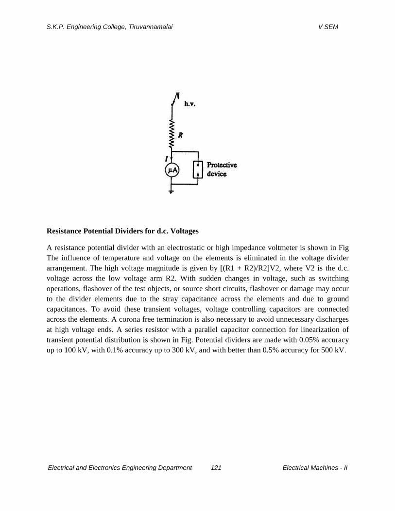
S.K.P. Engineering College, Tiruvannamalai V SEM
Electrical and Electronics Engineering Department 121 Electrical Machines - II
Resistance Potential Dividers for d.c. Voltages
A resistance potential divider with an electrostatic or high impedance voltmeter is shown in Fig
The influence of temperature and voltage on the elements is eliminated in the voltage divider
arrangement. The high voltage magnitude is given by [(R1 + R2)/R2]V2, where V2 is the d.c.
voltage across the low voltage arm R2. With sudden changes in voltage, such as switching
operations, flashover of the test objects, or source short circuits, flashover or damage may occur
to the divider elements due to the stray capacitance across the elements and due to ground
capacitances. To avoid these transient voltages, voltage controlling capacitors are connected
across the elements. A corona free termination is also necessary to avoid unnecessary discharges
at high voltage ends. A series resistor with a parallel capacitor connection for linearization of
transient potential distribution is shown in Fig. Potential dividers are made with 0.05% accuracy
up to 100 kV, with 0.1% accuracy up to 300 kV, and with better than 0.5% accuracy for 500 kV.

S.K.P. Engineering College, Tiruvannamalai V SEM
Electrical and Electronics Engineering Department 122 Electrical Machines - II
2.Explain with neat diagram Generating voltmeter.
Generating Voltmeters
High voltage measuring devices employ generating principle when source loading
is prohibited (as with Van de Graaff generators, etc.) or when direct connection to the
high voltage source is to be avoided. A generating voltmeter is a variable capacitor
electrostatic voltage generator which generates current proportional to the applied
external voltage. The device is driven by an external synchronous or constant speed
S.K.P. Engineering College, Tiruvannamalai V SEM
Electrical and Electronics Engineering Department 123 Electrical Machines - II
motor and does not absorb power or energy from the voltage measuring source. A
generating voltmeter with a rotating cylinder consists of two excitating field electrodes
and a rotating two pole armature driven by a synchronous motor at a constant speed n.
The a.c. current flowing between the two halves of the armature is rectified by a
commutator. This device can be used for measuring a.c. voltages provided the speed of
the drive-motor is half the frequency of the voltage to be measured. Thus a four-pole
synchronous motor with 1500 rpm is suitable for 50 Hz. For peak value measurements,
the phase angle of the motor must also be so adjusted that Cmax and the crest value
occur at the same instant. Generating voltmeters employ rotating sectors or vanes for
variation of capacitance. Figure gives a schematic diagram of a generating voltmeter.
The high voltage source is connected to a disc electrode S3 which is kept at a fixed
distance on the axis of the other low voltage electrodes S0, S1 and S2 The rotor S0 driven
at a constant speed by a synchronous motor at a suitable speed (1500,1800,3000, or 3600
rpm). The rotor vanes of S0 cause periodic change in capacitance between the insulated
disc S2 and the h.v. electrode S3. The shape and number of the vanes of S0 and S1 are so
designed that they produce sinusoidal variation in the capacitance. The generated a.c.
current through the resistance R is rectified and read by a moving coil instrument An
amplifier is needed, if the shunt capacitance is large or longer leads are used for
connection to rectifier and meter. The instrument is calibrated using a potential divider or
sphere gap. The meter scale is linear and its range can be extended
Advantages of Generating Voltmeters
(i) No source loading by the meter, (ii) no direct connection to high voltage electrode, (iii) scale is linear and extension of range is easy, and (i v) a very convenient instrument for electrostatic devices such as Van de Graaff generator and article accelerators.
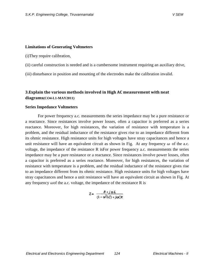
S.K.P. Engineering College, Tiruvannamalai V SEM
Electrical and Electronics Engineering Department 124 Electrical Machines - II
Limitations of Generating Voltmeters
(i)They require calibration,
(ii) careful construction is needed and is a cumbersome instrument requiring an auxiliary drive,
(iii) disturbance in position and mounting of the electrodes make the calibration invalid.
3.Explain the various methods involved in High AC measurement with neat
diagrams(CO4-L1-MAY2011)
Series Impedance Voltmeters
For power frequency a.c. measurements the series impedance may be a pure resistance or
a reactance. Since resistances involve power losses, often a capacitor is preferred as a series
reactance. Moreover, for high resistances, the variation of resistance with temperature is a
problem, and the residual inductance of the resistance gives rise to an impedance different from
its ohmic resistance. High resistance units for high voltages have stray capacitances and hence a
unit resistance will have an equivalent circuit as shown in Fig. At any frequency of the a.c.
voltage, the impedance of the resistance R isFor power frequency a.c. measurements the series
impedance may be a pure resistance or a reactance. Since resistances involve power losses, often
a capacitor is preferred as a series reactance. Moreover, for high resistances, the variation of
resistance with temperature is a problem, and the residual inductance of the resistance gives rise
to an impedance different from its ohmic resistance. High resistance units for high voltages have
stray capacitances and hence a unit resistance will have an equivalent circuit as shown in Fig. At
any frequency of the a.c. voltage, the impedance of the resistance R is
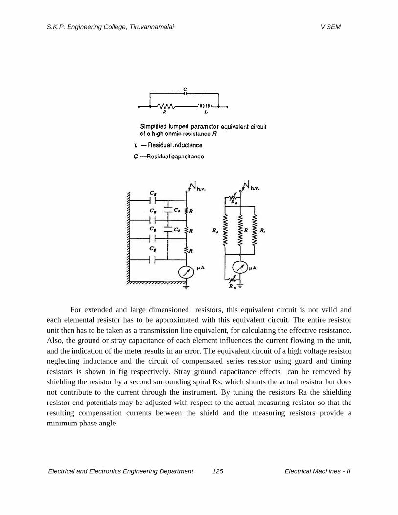
S.K.P. Engineering College, Tiruvannamalai V SEM
Electrical and Electronics Engineering Department 125 Electrical Machines - II
For extended and large dimensioned resistors, this equivalent circuit is not valid and
each elemental resistor has to be approximated with this equivalent circuit. The entire resistor
unit then has to be taken as a transmission line equivalent, for calculating the effective resistance.
Also, the ground or stray capacitance of each element influences the current flowing in the unit,
and the indication of the meter results in an error. The equivalent circuit of a high voltage resistor
neglecting inductance and the circuit of compensated series resistor using guard and timing
resistors is shown in fig respectively. Stray ground capacitance effects can be removed by
shielding the resistor by a second surrounding spiral Rs, which shunts the actual resistor but does
not contribute to the current through the instrument. By tuning the resistors Ra the shielding
resistor end potentials may be adjusted with respect to the actual measuring resistor so that the
resulting compensation currents between the shield and the measuring resistors provide a
minimum phase angle.
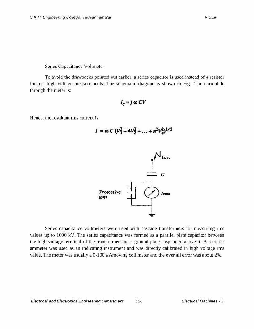
S.K.P. Engineering College, Tiruvannamalai V SEM
Electrical and Electronics Engineering Department 126 Electrical Machines - II
Series Capacitance Voltmeter
To avoid the drawbacks pointed out earlier, a series capacitor is used instead of a resistor
for a.c. high voltage measurements. The schematic diagram is shown in Fig.. The current Ic
through the meter is:
Hence, the resultant rms current is:
Series capacitance voltmeters were used with cascade transformers for measuring rms
values up to 1000 kV. The series capacitance was formed as a parallel plate capacitor between
the high voltage terminal of the transformer and a ground plate suspended above it. A rectifier
ammeter was used as an indicating instrument and was directly calibrated in high voltage rms
value. The meter was usually a 0-100 Amoving coil meter and the over all error was about 2%.
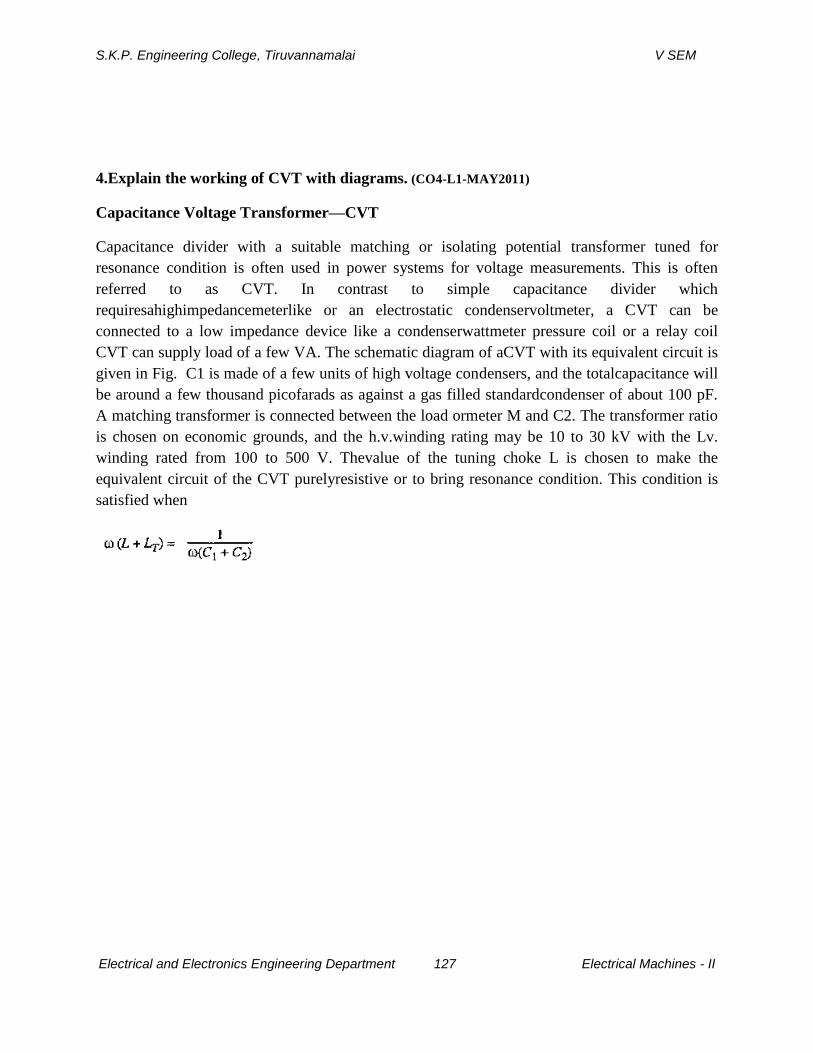
S.K.P. Engineering College, Tiruvannamalai V SEM
Electrical and Electronics Engineering Department 127 Electrical Machines - II
4.Explain the working of CVT with diagrams. (CO4-L1-MAY2011)
Capacitance Voltage Transformer—CVT
Capacitance divider with a suitable matching or isolating potential transformer tuned for
resonance condition is often used in power systems for voltage measurements. This is often
referred to as CVT. In contrast to simple capacitance divider which
requiresahighimpedancemeterlike or an electrostatic condenservoltmeter, a CVT can be
connected to a low impedance device like a condenserwattmeter pressure coil or a relay coil
CVT can supply load of a few VA. The schematic diagram of aCVT with its equivalent circuit is
given in Fig. C1 is made of a few units of high voltage condensers, and the totalcapacitance will
be around a few thousand picofarads as against a gas filled standardcondenser of about 100 pF.
A matching transformer is connected between the load ormeter M and C2. The transformer ratio
is chosen on economic grounds, and the h.v.winding rating may be 10 to 30 kV with the Lv.
winding rated from 100 to 500 V. Thevalue of the tuning choke L is chosen to make the
equivalent circuit of the CVT purelyresistive or to bring resonance condition. This condition is
satisfied when
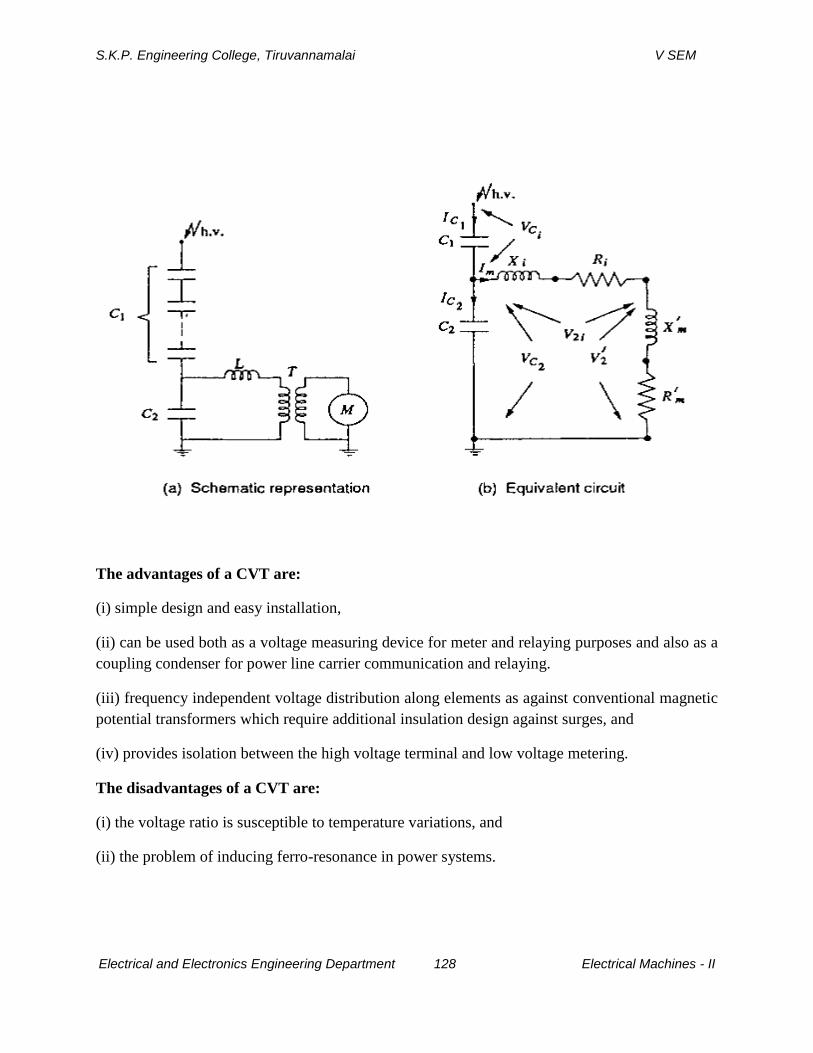
S.K.P. Engineering College, Tiruvannamalai V SEM
Electrical and Electronics Engineering Department 128 Electrical Machines - II
The advantages of a CVT are:
(i) simple design and easy installation,
(ii) can be used both as a voltage measuring device for meter and relaying purposes and also as a
coupling condenser for power line carrier communication and relaying.
(iii) frequency independent voltage distribution along elements as against conventional magnetic
potential transformers which require additional insulation design against surges, and
(iv) provides isolation between the high voltage terminal and low voltage metering.
The disadvantages of a CVT are:
(i) the voltage ratio is susceptible to temperature variations, and
(ii) the problem of inducing ferro-resonance in power systems.
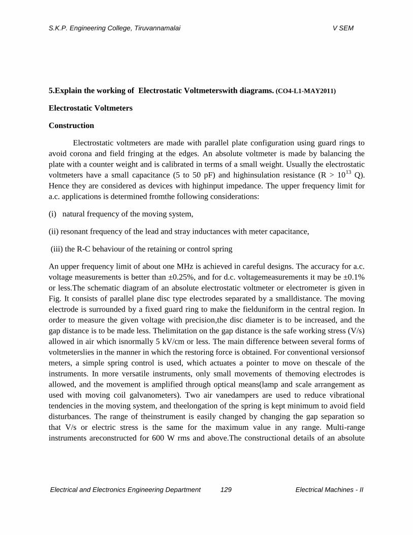
S.K.P. Engineering College, Tiruvannamalai V SEM
Electrical and Electronics Engineering Department 129 Electrical Machines - II
5.Explain the working of Electrostatic Voltmeterswith diagrams. (CO4-L1-MAY2011)
Electrostatic Voltmeters
Construction
Electrostatic voltmeters are made with parallel plate configuration using guard rings to
avoid corona and field fringing at the edges. An absolute voltmeter is made by balancing the
plate with a counter weight and is calibrated in terms of a small weight. Usually the electrostatic
voltmeters have a small capacitance (5 to 50 pF) and highinsulation resistance (R > 1013
Q).
Hence they are considered as devices with highinput impedance. The upper frequency limit for
a.c. applications is determined fromthe following considerations:
(i) natural frequency of the moving system,
(ii) resonant frequency of the lead and stray inductances with meter capacitance,
(iii) the R-C behaviour of the retaining or control spring
An upper frequency limit of about one MHz is achieved in careful designs. The accuracy for a.c.
voltage measurements is better than ±0.25%, and for d.c. voltagemeasurements it may be ±0.1%
or less.The schematic diagram of an absolute electrostatic voltmeter or electrometer is given in
Fig. It consists of parallel plane disc type electrodes separated by a smalldistance. The moving
electrode is surrounded by a fixed guard ring to make the fielduniform in the central region. In
order to measure the given voltage with precision,the disc diameter is to be increased, and the
gap distance is to be made less. Thelimitation on the gap distance is the safe working stress (V/s)
allowed in air which isnormally 5 kV/cm or less. The main difference between several forms of
voltmeterslies in the manner in which the restoring force is obtained. For conventional versionsof
meters, a simple spring control is used, which actuates a pointer to move on thescale of the
instruments. In more versatile instruments, only small movements of themoving electrodes is
allowed, and the movement is amplified through optical means(lamp and scale arrangement as
used with moving coil galvanometers). Two air vanedampers are used to reduce vibrational
tendencies in the moving system, and theelongation of the spring is kept minimum to avoid field
disturbances. The range of theinstrument is easily changed by changing the gap separation so
that V/s or electric stress is the same for the maximum value in any range. Multi-range
instruments areconstructed for 600 W rms and above.The constructional details of an absolute
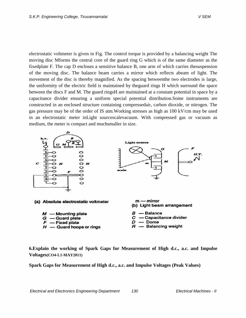
S.K.P. Engineering College, Tiruvannamalai V SEM
Electrical and Electronics Engineering Department 130 Electrical Machines - II
electrostatic voltmeter is given in Fig. The control torque is provided by a balancing weight The
moving disc Mforms the central core of the guard ring G which is of the same diameter as the
fixedplate F. The cap D encloses a sensitive balance B, one arm of which carries thesuspension
of the moving disc. The balance beam carries a mirror which reflects abeam of light. The
movement of the disc is thereby magnified. As the spacing betweenthe two electrodes is large,
the uniformity of the electric field is maintained by theguard rings H which surround the space
between the discs F and M. The guard ringsH are maintained at a constant potential in space by a
capacitance divider ensuring a uniform special potential distribution.Some instruments are
constructed in an enclosed structure containing compressedair, carbon dioxide, or nitrogen. The
gas pressure may be of the order of IS atm.Working stresses as high as 100 kV/cm may be used
in an electrostatic meter inLight sourcescalevacuum. With compressed gas or vacuum as
medium, the meter is compact and muchsmaller in size.
6.Explain the working of Spark Gaps for Measurement of High d.c., a.c. and Impulse
Voltages(CO4-L1-MAY2011)
Spark Gaps for Measurement of High d.c., a.c. and Impulse Voltages (Peak Values)
S.K.P. Engineering College, Tiruvannamalai V SEM
Electrical and Electronics Engineering Department 131 Electrical Machines - II
A uniform field spark gap will always have a sparkover voltage within a known tolerance
under constant atmospheric conditions. Hence a spark gap can be used for measurement of the
peak value of the voltage, if the gap distance is known. A sparkover voltage of 30 kV (peak) at 1
cm spacing in air at 2O0 C and 760 torr pressure occurs for a sphere gap or any uniform field
gap. But experience has shown that these measurements are reliable only for certain gap
configurations. Normally, only sphere gaps are used for voltage measurements. In certain cases
uniform field gaps and rod gaps are also used, but their accuracy is less. The spark gap
breakdown, especially the sphere gap breakdown, is independent of the voltage waveform and
hence is highly suitable for all types of waveforms from d.c. to impulse voltages of short rise
times(rise time > 0.5 M. s). As such, sphere gaps can be used for radio frequency a.c. voltage
peak measurements also (up to 1 MHz).Sphere Gap Measurements Sphere gaps can be arranged
either (i) vertically with lower sphere grounded, or (ii)horizontally with both spheres connected
to the source voltage or one sphere grounded. In horizontal configurations, it is generally
arranged such that both spheres are symmetrically at high voltage above the ground. The two
spheres used are identical in size and shape. The schematic arrangement is shown in Figs.. The
voltage to be measured is applied between the two spheres and the distance or spacing 5 between
them gives a measure of the sparkover voltage. A series resistance is usually connected between
the source and the sphere gap to (i) limit the breakdown current, and (ii) to suppress unwanted
oscillations in the source voltage when breakdown occurs (in case of impulse voltages). The
value of the series resistance may vary from 100 to 1000 kilo ohms for a.c. or d.c. voltages and
not more In the case of a.c. peak value and d.c. voltage measurements, the applied voltage is
uniformly increased until sparkover occurs in the gap. Generally, a mean of about five
breakdown values is taken when they agree to within ±3%. In the case of impulse voltages, to
obtain 50% flashover voltage, two voltage limits, differing by not more than 2% are set such that
on application of lower limit value either 2 or 4 flashovers take place and on application of upper
limit value 8 or 6 flashovers take place respectively. The mean of these two limits is taken as
50% flashover voltage. In any case, a preliminary sparkover voltage measurement is to be made
before actual measurements are made.

S.K.P. Engineering College, Tiruvannamalai V SEM
Electrical and Electronics Engineering Department 132 Electrical Machines - II

S.K.P. Engineering College, Tiruvannamalai V SEM
Electrical and Electronics Engineering Department 133 Electrical Machines - II
Factors Influencing the Sparkover Voltage of Sphere Gaps
Various factors that affect the sparkover voltage of a sphere gap are:
(i) nearby earthed objects,
(ii) atmospheric conditions and humidity,
(iii) irradiation, and
(iv) polarity and rise time of voltage waveforms.
(i) Effect of nearby earthed objects
The effect of nearby earthed objects was investigated by enclosing the earthed sphere
inside an earthed cylinder. It was observed that the sparkovervoltage is reduced. The reduction
was observed to be
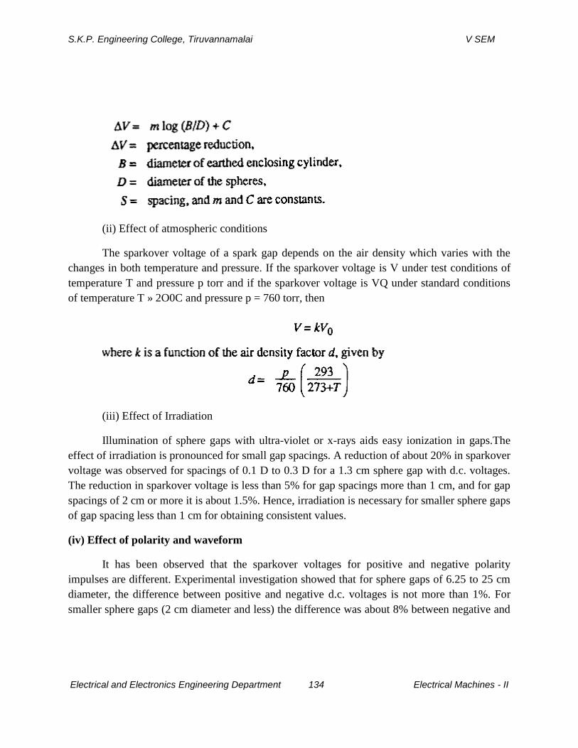
S.K.P. Engineering College, Tiruvannamalai V SEM
Electrical and Electronics Engineering Department 134 Electrical Machines - II
(ii) Effect of atmospheric conditions
The sparkover voltage of a spark gap depends on the air density which varies with the
changes in both temperature and pressure. If the sparkover voltage is V under test conditions of
temperature T and pressure p torr and if the sparkover voltage is VQ under standard conditions
of temperature T » 2O0C and pressure p = 760 torr, then
(iii) Effect of Irradiation
Illumination of sphere gaps with ultra-violet or x-rays aids easy ionization in gaps.The
effect of irradiation is pronounced for small gap spacings. A reduction of about 20% in sparkover
voltage was observed for spacings of 0.1 D to 0.3 D for a 1.3 cm sphere gap with d.c. voltages.
The reduction in sparkover voltage is less than 5% for gap spacings more than 1 cm, and for gap
spacings of 2 cm or more it is about 1.5%. Hence, irradiation is necessary for smaller sphere gaps
of gap spacing less than 1 cm for obtaining consistent values.
(iv) Effect of polarity and waveform
It has been observed that the sparkover voltages for positive and negative polarity
impulses are different. Experimental investigation showed that for sphere gaps of 6.25 to 25 cm
diameter, the difference between positive and negative d.c. voltages is not more than 1%. For
smaller sphere gaps (2 cm diameter and less) the difference was about 8% between negative and
S.K.P. Engineering College, Tiruvannamalai V SEM
Electrical and Electronics Engineering Department 135 Electrical Machines - II
positive impulses of 1/50 s waveform. Similarly, the wave front and wave tail durations also
influence the breakdown voltage. For wave fronts of less than 0.5 s and wave tails less than 5
s the breakdown voltages are not consistent and hence the use of sphere gap is not
recommended for voltage measurement in such cases.
7. Explain the working of measurement of high d.c.,a .c. and impulse currents (CO4-L1-
MAY2011)
MEASUREMENT OF HIGH D.C.,A .C. AND IMPULSE CURRENTS
In power systems, it is often necessary to measure high currents, arising due to short
circuits. For conducting temperature rise and heat run tests on power equipment’s like
conductors, cables, circuit breakers, etc., measurement of high currents is required. During
lightning discharges and switching transients also, large magnitudes of impulse and switching
surge currents occur, which require special measuring techniques at high potential levels.
Measurement of High Direct Currents
High magnitude direct currents are measured using a resistive shunt of low ohmic value.
The voltage drop across the resistance is measured with a millivoltmeter. Thevalue of the
resistance varies usually between 10 and 13 mΩ. This depends on theheating effect and the
loading permitted in the circuit. High current resistors areusually oil immersed and are made as
three or four terminal resistances .The voltage drop across the shunt is limited to a few millivolts
(< 1 Volt) in powercircuits.
Hall Generators for d.c. Current Measurements
The principle of the "Hall effect" is made use of in measuring very high direct
currents. If an electric current flows through a metal plate located in a magnetic field
perpendicular to it, Lorenz forces will deflect the electrons in the metal structure in a
direction normal to the direction of both the current and the magnetic field. The charge
displacement generates an emf in the normal direction, called the'HaIl voltage'. The Hall
voltage is proportional to the current i, the magnetic flux density B, and the reciprocal of
the plate thickness d; the proportionality constant R is called the ―HaIlcoefficient".or
metals the Hall coefficient is very small, and hence semi-conductor materials are used for
which the Hall coefficient is high.In large current measurements, the current carrying
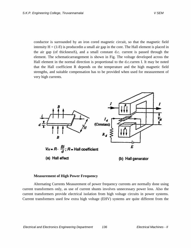
S.K.P. Engineering College, Tiruvannamalai V SEM
Electrical and Electronics Engineering Department 136 Electrical Machines - II
conductor is surrounded by an iron cored magnetic circuit, so that the magnetic field
intensity H = (1/ ) is producedin a small air gap in the core. The Hall element is placed in
the air gap (of thicknessS), and a small constant d.c. current is passed through the
element. The schematicarrangement is shown in Fig. The voltage developed across the
Hall element in the normal direction is proportional to the d.c.curren I. It may be noted
that the Hall coefficient R depends on the temperature and the high magnetic field
strengths, and suitable compensation has to be provided when used for measurement of
very high currents.
Measurement of High Power Frequency
Alternating Currents Measurement of power frequency currents are normally done using
current transformers only, as use of current shunts involves unnecessary power loss. Also the
current transformers provide electrical isolation from high voltage circuits in power systems.
Current transformers used few extra high voltage (EHV) systems are quite different from the
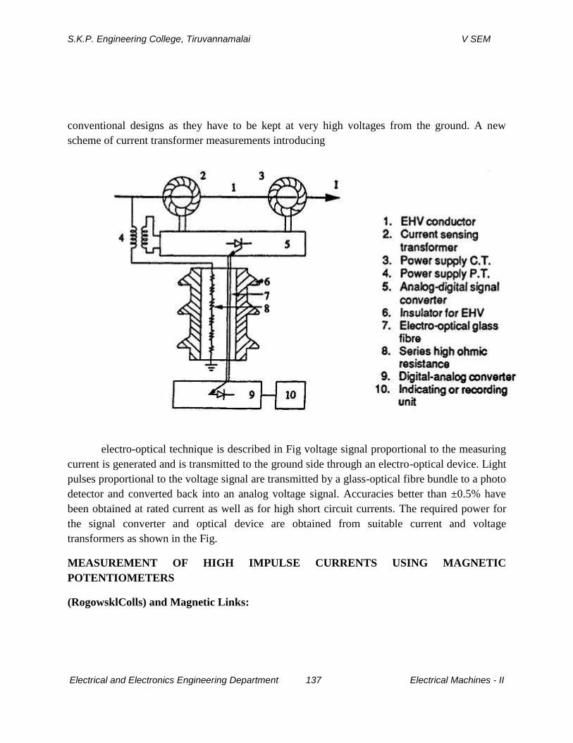
S.K.P. Engineering College, Tiruvannamalai V SEM
Electrical and Electronics Engineering Department 137 Electrical Machines - II
conventional designs as they have to be kept at very high voltages from the ground. A new
scheme of current transformer measurements introducing
electro-optical technique is described in Fig voltage signal proportional to the measuring
current is generated and is transmitted to the ground side through an electro-optical device. Light
pulses proportional to the voltage signal are transmitted by a glass-optical fibre bundle to a photo
detector and converted back into an analog voltage signal. Accuracies better than ±0.5% have
been obtained at rated current as well as for high short circuit currents. The required power for
the signal converter and optical device are obtained from suitable current and voltage
transformers as shown in the Fig.
MEASUREMENT OF HIGH IMPULSE CURRENTS USING MAGNETIC
POTENTIOMETERS
(RogowsklColls) and Magnetic Links:
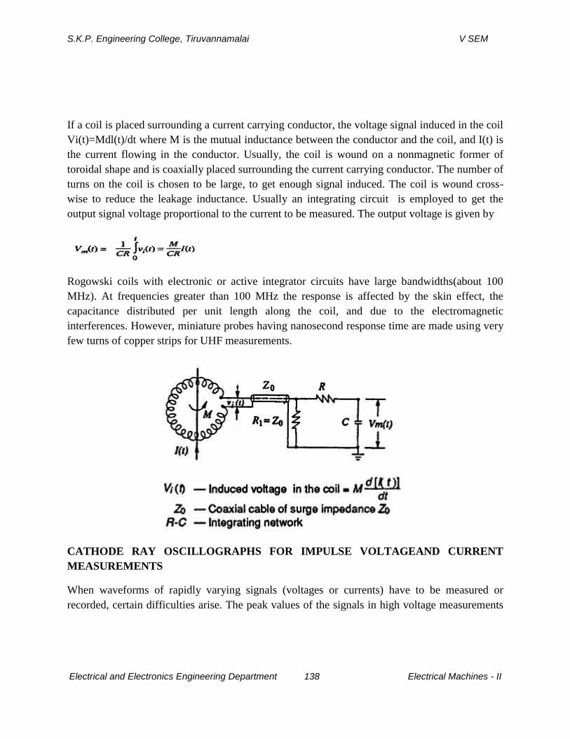
S.K.P. Engineering College, Tiruvannamalai V SEM
Electrical and Electronics Engineering Department 138 Electrical Machines - II
If a coil is placed surrounding a current carrying conductor, the voltage signal induced in the coil
Vi(t)=Mdl(t)/dt where M is the mutual inductance between the conductor and the coil, and I(t) is
the current flowing in the conductor. Usually, the coil is wound on a nonmagnetic former of
toroidal shape and is coaxially placed surrounding the current carrying conductor. The number of
turns on the coil is chosen to be large, to get enough signal induced. The coil is wound cross-
wise to reduce the leakage inductance. Usually an integrating circuit is employed to get the
output signal voltage proportional to the current to be measured. The output voltage is given by
Rogowski coils with electronic or active integrator circuits have large bandwidths(about 100
MHz). At frequencies greater than 100 MHz the response is affected by the skin effect, the
capacitance distributed per unit length along the coil, and due to the electromagnetic
interferences. However, miniature probes having nanosecond response time are made using very
few turns of copper strips for UHF measurements.
CATHODE RAY OSCILLOGRAPHS FOR IMPULSE VOLTAGEAND CURRENT
MEASUREMENTS
When waveforms of rapidly varying signals (voltages or currents) have to be measured or
recorded, certain difficulties arise. The peak values of the signals in high voltage measurements
S.K.P. Engineering College, Tiruvannamalai V SEM
Electrical and Electronics Engineering Department 139 Electrical Machines - II
are too large, may be several kilovolts or kiloamperes. Therefore, direct measurement is not
possible. The magnitudes of these signals are scaled down by voltage dividers or shunts to
smaller voltage signals. The reduced signal Vm(f) is normally proportional to the measured
quantity. The procedure of transmitting the signal and displaying or recording it is very
important The associated electromagnetic fields with rapidly changing signals induce disturbing
voltages,which have to be avoided. The problems associated in the above procedure are
discussed in this section Cathode Ray Oscillographs for Impulse Measurements Modern
oscillographs are sealed tube hot cathode oscilloscopes with photographic arrangement for
recording the waveforms. The cathode ray oscilloscope for impulse work normally has input
voltage range from 5 m V/cm to about 20 V/cm. In addition,there are probes and attenuators to
handle signals up to 600 V (peak to peak). The bandwidth and rise time of the oscilloscope
should be adequate. Rise times of 5 n sand bandwidth as high as 500 MHz may be
necessary.Sometimes high voltage surge test oscilloscopes do not have vertical amplifier and
directly require an input voltage of 10 V. They can take a maximum signal of about100 V (peak
to peak) but require suitable attenuators for large signals.Oscilloscopes are fitted with good
cameras for recording purposes. Tektronix model 7094 is fitted with a lens of 1: 1.2 polaroid
camera which uses 10,000 ASA film which possesses a writing speed of 9 cm/ns. With rapidly
changing signals, it is necessary to initiate or start the oscilloscope time base before the signal
reaches the oscilloscope deflecting plates, otherwise a portion of the signal may be missed. Such
measurements require an accurate initiation of the horizontal time base and is known as
triggering. Oscilloscopes are normally provided with both internal and external triggering
facility. When external triggeringis used, as with recording of impulses, the signal is directly fed
to actuate the time
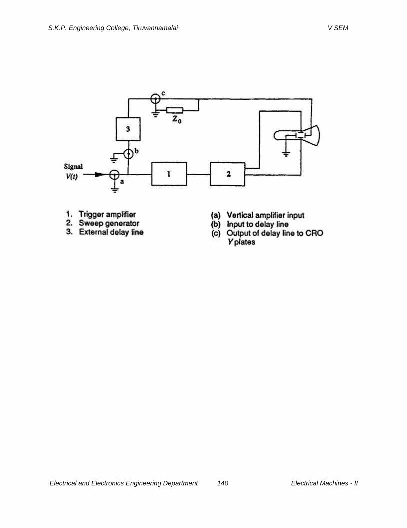
S.K.P. Engineering College, Tiruvannamalai V SEM
Electrical and Electronics Engineering Department 140 Electrical Machines - II
S.K.P. Engineering College, Tiruvannamalai V SEM
Electrical and Electronics Engineering Department 141 Electrical Machines - II
UNIT 5
HIGH VOLTAGE TESTING AND INSULATION COORDINATION
PART A
1.What are tests conducted on insulators? (CO5-L1-MAY2013)
i) Power frequency voltage test
ii) Impulse voltage test
Power frequency test can be classified into
a) Dry and wet flashover tests
b) Wet and dry withstand tests (one minute)
Impulse tests can be classified into
a) Impulse withstand voltage test
b) Impulse flashover test
c) Pollution testing.
2.What are test conducted on Bushings? (CO5-L1-MAY2013)
i) Power frequency voltage test
ii) Impulse voltage test
Power frequency test can be classified into
a) Power factor voltage test
b) Internal or partial discharge test
c) Momentary withstand test at power frequency
d) One minute wet withstand test at power frequency test
e) Visible discharge test at power frequency
mpulse voltage tests can be classified into
a) Full wave withstand test
S.K.P. Engineering College, Tiruvannamalai V SEM
Electrical and Electronics Engineering Department 142 Electrical Machines - II
b) Chopped wave withstand and switching surge test
C]Temperature rise and thermal stability tests are also used for testing of
bushings.
3.Define withstand voltage. (CO5-L1-MAY2013)
The voltage which has to be applied to attest object under specified condition in a
withstand test is called the withstand voltage.
4.Define impulse voltage. (CO5-L1-MAY2013)
Impulse voltage is characterized by polarity. Peak value, time to front and time to
half the peak value after the peak. The time to front is defined as 1.67 times to time
between 30 5 and 90 % of the peak value in the rising portion of the wave.
According to [s : 207] (1973) standard impulse is defined as one with tf = 1.2 µs, tt =
50 µs (called 1.250 µs wave). The tolerances allowed are ±3 % on the peak value,
±30 % in the front time (tf), and ±20 % in the tail time (tt).
5.Differentiate type test and routine test. (CO5-L1-MAY2013)
Routine test is not to flash over the insulator but rather to detect existing fault
before the insulator is put in service .Type test cover those features that are
important to the purchaser such as dry and wet flash over, puncture voltage, tensile
strength.
6.Define Disruptive discharge voltage. (CO5-L1-MAY2013)
This is defined as the voltage which produces the loss of dielectric strength of an
insulation. It is that voltage at which the electrical stress in the insulation causes a
failure which includes the collapses of voltage and passage of current.
S.K.P. Engineering College, Tiruvannamalai V SEM
Electrical and Electronics Engineering Department 143 Electrical Machines - II
7.What are the atmosphere correction factor and mention their influence in high
voltage testing. (CO5-L1-MAY2013)
Actual air density during measurement differs due to temperature and pressure
variation.
Spark over voltage depends upon the air density factor
Spark over voltage V = KV0
Where ,K = Correction factor related to air density factor‘d’
V0 = Spark over voltage under standard temperature and pressure.
d = P/P0[(273 + t0) / (273 + T)]
Where
K is a function of air density factor d
P = air pressure at test condition
P0 =air pressure at standard condition
t0 = temperature at standard condition
T = temperature at test condition
8.Explain the role of Bureau of Indian standards in high voltage testing. (CO5-L1-
MAY2013)
All the EHV equipment voltage are governed by Indian standard specification issued
by Bureau of Indian standards in our country.
For different transmission voltages the test voltages are given in a tubular form.
9.Define insulation co- ordination. (CO5-L1-MAY2013)
S.K.P. Engineering College, Tiruvannamalai V SEM
Electrical and Electronics Engineering Department 144 Electrical Machines - II
Insulation co-ordination of suitable values for the insulation levels of the various
components in any electrical system and their management in a rational manner is
called insulation co-ordination Insulation co-ordination of the insulation of the
electrical equipment and circuits with the characteristics of the protective devices in
such a manner that the insulation is well protected from the excessive over voltages.
10.What is the significance of impulse tests? (CO5-L1-MAY2013)
Impulse test are done on insulator to ensure reliability of individual test objects and
quality and consistency of material used in their manufacture and done on
transformers is to determine the ability of the insulation of transformers to
withstand the transient voltages due to lightning.
11.Name the different types of tests conducted on high voltage apparatus. (CO5-
L1-MAY2013)
Dry -Wet flashover test and Dry -Wet withstands test are the two types of tests
conducted on high voltage apparatus.
12.Explain the reasons for conducting wet tests on high voltage apparatus and
give the specifications of the water used for wet tests. (CO5-L1-MAY2013)
Wet tests are to provide a criterion based on experience that a satisfactory service
operation will be obtained.
Conductivity of water 100 microsiemens ± 10 %
Water temperature ambient ± 15 %
13.Definecreepage distance. (CO5-L1-MAY2013)
S.K.P. Engineering College, Tiruvannamalai V SEM
Electrical and Electronics Engineering Department 145 Electrical Machines - II
It is the shortest distance of contour of the external surface of the insulator unit or
between two metal fittings on the insulator.
14.Give the Indian standard reference atmospheric conditions for high voltage
testing. (CO5-L1-MAY2013)
a) Temperature - 27°C
b) Pressure - 1013 millibars (or 70 torr)
c) Absolute humidity – 17 gm/m3
15.Define safety margin as applied to be insulation co-ordination. (CO5-L1-
MAY2013)
Safety margin applied to insulation co-ordination is the basic insulation level of
equipment is defined as the peak voltage of 1.2 / 50 µs wave which does not cause
insulation to fail. The definition of a surge (1.2 / 50 µs) indicates a surge which
reaches its peak value in 1.2 µs and decays to half the peak in 50 µs.
PART B
1.Mention the different Electrical test on Over Head insulators(CO5-L1-MAY2013)
S.K.P. Engineering College, Tiruvannamalai V SEM
Electrical and Electronics Engineering Department 146 Electrical Machines - II
TESTING OF OVERHEAD LINE INSULATORS
Various types of overhead line insulators are
(i)Pin type
(ii)Post type
(iii)String insulator unit
(iv) Suspension insulator string
(v) Tension insulator.
Arrangement of Insulators for Test
String insulator unit should be hung by a suspension eye from an earthed metal cross arm.
The test voltage is applied between the cross arm and the conductor hung vertically down from
the metal part on the lower side of the insulator unit.Suspension string with all its accessories as
in service should be hung from an earthed metal cross arm. The length of the cross arm should be
at least 1.5 times the length of the string being tested and should be at least equal to 0.9 m on
either side of the axis of the string. No other earthed object should be nearer to the insulator
string then 0.9 m or 1.5 times the length of the string whichever is greater. A conductor of actual
size to be used in service or of diameter not less than 1 cm and length 1.5times the length of the
string is secured in the suspension clamp and should lie in a horizontal plane.The test voltage is
applied between the conductor and the cross arm and connection from the impulse generator is
made with a length of wire to one end of the conductor. For higher operating voltages where the
length of the string is large, it is advisable to sacrifice the length of the conductor as stipulated
above. Instead, it is desirable to bend the ends of the conductor over in a large radius.For tension
insulators the arrangement is more or less same as in suspension insulator except that it should be
held in an approximately horizontal position under a suitable tension (about 1000 Kg.).For
testing pin insulators or line post insulators, these should be mounted on the insulator pin or line
post shank with which they are to be used in service. The pin or the shank should be fixed in a
vertical position to a horizontal earthed metal cross arm situated 0.9 m above the floor of the
laboratory.A conductor of 1 cm diameter is to be laid horizontally in the top groove of the
insulator and secured by at least one turn of tie-wire, not less than 0.3 cm diameter in the tie-wire
groove. The length of the wire should be at least 1.5 times the length of the insulator and should
S.K.P. Engineering College, Tiruvannamalai V SEM
Electrical and Electronics Engineering Department 147 Electrical Machines - II
over hang the insulator at least 0.9 mm either side in a direction at right angles to the cross arm.
The test voltage is applied to one end of the conductor.
High voltage testing of electrical equipment requires two types of tests:
(i) Type tests, and
(ii) Routine test.
Type tests involves quality testing of equipment at the design and development level
i.e.samples of the product are taken and are tested when a new product is being developed and
designed or an old product is to be redesigned and developed whereas the routine tests are
meant to check the quality of the individual test piece. This is carried out to ensure quality and
reliability of individual test objects.High voltage tests include
(i) Power frequency tests and
(ii) Impulse tests.
These tests are carried out on all insulators.
(i) 50% dry impulse flash over test.
(ii) Impulse withstand test.
(iii) Dry flash over and dry one minute test.
(iv) Wet flash over and one minute rain test.
(v) Temperature cycle test.
(vi) Electro-mechanical test.
(vii) Mechanical test.
(viii) Porosity test.
(ix) Puncture test.
(x) Mechanical routine test.
The tests mentioned above are briefly described here.
S.K.P. Engineering College, Tiruvannamalai V SEM
Electrical and Electronics Engineering Department 148 Electrical Machines - II
(i) The test is carried out on a clean insulator mounted as in a normal working condition. An
impulse voltage of 1/50 µ sec. wave shape and of an amplitude which can cause 50% flash over
of the insulator, is applied, i.e. of the impulses applied 50% of the impulses should cause flash
over. The polarity of the impulse is then reversed and procedure repeated. There must be at least
20 applications of the impulse in each case and the insulator must not be damaged. The
magnitude of the impulse voltage should not be less than that specified in standard
specifications.
(ii) The insulator is subjected to standard impulse of 1/50 µ sec. wave of specified value under
dry conditions with both positive and negative polarities. If five consecutive applications do not
cause any flash over or puncture, the insulator is deemed to have passed the impulse withstand
test. If out of five, two applications cause flash over, the insulator is deemed to have filed the
test.
(iii) Power frequency voltage is applied to the insulator and the voltage increased to the
specified value and maintained for one minute. The voltage is then increased gradually
until flash over occurs. The insulator is then flashed over at least four more times, the
voltage is raised gradually to reach flash over in about 10 seconds. The mean of at least
five consecutive flash over voltages must not be less than the value specified in
specifications.
(iv) If the test is carried out under artificial rain, it is called wet flash over test. The insulator is
subjected to spray of water of following characteristics:
The insulator with 50% of the one-min. rain test voltage applied to it, is then sprayed for
two minutes, the voltage raised to the one minute test voltage in approximately 10 sec. and
maintained there for one minute. The voltage is then increased gradually till flash over occurs
and the insulator is then lashed at least four more times, the time taken to reach flash over
S.K.P. Engineering College, Tiruvannamalai V SEM
Electrical and Electronics Engineering Department 149 Electrical Machines - II
voltage being in each case about10 sec. The flash over voltage must not be less than the value
specified in specifications.
(v) The insulator is immersed in a hot water bath whose temperature is 70° higher than normal
water bath for T minutes. It is then taken out and immediately immersed in normal water bath
for T minutes. After T minutes the insulator is again immersed in hot water bath for T minutes.
The cycle is repeated three times and it is expected that the insulator should withstand the test
without damage to the insulator or glaze. Here T = (15 + W/1.36) where W is the weight of the
insulator in kgs.
(vi) The test is carried out only on suspension or tension type of insulator. The insulator is
subjected to a 2½ times the specified maximum working tension maintained for one minute.
Also,simultaneously 75% of the dry flash over voltage is applied. The insulator should withstand
this test without any damage.
(vii) This is a bending test applicable to pin type and line-post insulators. The insulator is
subjected to a load three times the specified maximum breaking load for one minute. There
should be no damage to the insulator and in case of post insulator the permanent set must be less
than 1%. However,in case of post insulator, the load is then raised to three times and there should
not be any damage to the insulator and its pin.
(viii) The insulator is broken and immersed in a 0.5% alcohol solution of fuchsin under a
pressure of 13800 kN/m2 for 24 hours. The broken insulator is taken out and further broken. It
should not show any sign of impregnation.
(ix) An impulse over voltage is applied between the pin and the lead foil bound over the top and
side grooves in case of pin type and post insulator and between the metal fittings in case of
suspension type insulators. The voltage is 1/50 µ sec. wave with amplitude twice the 50%
impulse flash overvoltage and negative polarity. Twenty such applications are applied. The
procedure is repeated for 2.5,3, 3.5 times the 50% impulse flash over voltage and continued till
the insulator is punctured. The insulator must not puncture if the voltage applied is equal to the
one specified in the specification.
(x) The string in insulator is suspended vertically or horizontally and a tensile load 20% in excess
of the maximum specified working load is applied for one minute and no damage to the string
should occur.
S.K.P. Engineering College, Tiruvannamalai V SEM
Electrical and Electronics Engineering Department 150 Electrical Machines - II
2.What are the different test conducted on cables ?explain any one of them. (CO5-L1-
MAY2013)
TESTING OF CABLES
High voltage power cables have proved quite useful especially in case of HV d.c.
transmission. Under ground distribution using cables not only adds to the aesthetic looks of a
metropolitan city but it provides better environments and more reliable supply to the consumers.
Preparation of Cable Sample
The cable sample has to be carefully prepared for performing various tests especially
electrical tests.This is essential to avoid any excessive leakage or end flash overs which
otherwise may occur during testing and hence may give wrong information regarding the quality
of cables. The length of the sample cable varies between 50 cms to 10 m. The terminations are
usually made by shielding the ends of the cable with stress shields so as to relieve the ends from
excessive high electrical stresses.
A cable is subjected to following tests:
(i) Bending tests.
(ii) Loading cycle test.
(iii) Thermal stability test.
(iv) Dielectric thermal resistance test.
(v) Life expectancy test.
(vi) Dielectric power factor test.
(vii) Power frequency withstand voltage test.
(viii) Impulse withstand voltage test.
(ix) Partial discharge test.
S.K.P. Engineering College, Tiruvannamalai V SEM
Electrical and Electronics Engineering Department 151 Electrical Machines - II
(i) It is to be noted that a voltage test should be made before and after a bending test. The cable is
bent round a cylinder of specified diameter to make one complete turn. It is then unwound and
rewound in the opposite direction. The cycle is to be repeated three times.
(ii) A test loop, consisting of cable and its accessories is subjected to 20 load cycles with a
minimum conductor temperature 5°C in excess of the design value and the cable is energized
to1.5 times the working voltage. The cable should not show any sign of damage.
(iii) After test as at (ii), the cable is energized with a voltage 1.5 times the working voltage for a
cable of 132 kV rating (the multiplying factor decreases with increases in operating voltage) and
the loading current is so adjusted that the temperature of the core of the cable is 5°C higher than
its specified permissible temperature. The current should be maintained at this value for six
hours.
(iv) The ratio of the temperature difference between the core and sheath of the cable and the heat
low from the cable gives the thermal resistance of the sample of the cable. It should be within the
limits specified in the specifications.
(v) In order to estimate life of a cable, an accelerated life test is carried out by subjecting the
cable to a voltage stress higher than the normal working stress. It has been observed that the
relation between the expected life of the cable in hours and the voltage stress is given by
where K is a constant which depends on material and n is the life index depending again on the
material.
(vi) High Voltage Schering Bridge is used to perform dielectric power factor test on the cable
sample. The power factor is measured for different values of voltages e.g. 0.5, 1.0, 1.5 and 2.0
Times the rated operating voltages. The maximum value of power factor at normal working
voltage does not exceed a specified value (usually 0.01) at a series of temperatures ranging from
15°C to 65°C. The difference in the power factor between rated voltage and 1.5 times the rated
voltage and the rated voltage and twice the rated voltage does not exceed a specified value.
S.K.P. Engineering College, Tiruvannamalai V SEM
Electrical and Electronics Engineering Department 152 Electrical Machines - II
Sometimes the source is not able to supply charging current required by the test cable, a suitable
choke in series with the test cable helps in tiding over the situation.
(vii) Cables are tested for power frequency a.c. and d.c. voltages. During manufacture the
entirecable is passed through a higher voltage test and the rated voltage to check the continuity of
the cable.As a routine test the cable is subjected to a voltage 2.5 times the working voltage for 10
min without damaging the insulation of the cable. HV d.c. of 1.8 times the rated d.c. voltage of
negative polarity for30 min. is applied and the cable is said to have withstood the test if no
insulation failure takes place.
(viii) The test cable is subjected to 10 positive and 10 negative impulse voltage of magnitude as
specified in specification, the cable should withstand 5 applications without any damage.
Usually, after the impulse test, the power frequency dielectric power factor test is carried out to
ensure that no failure occurred during the impulse test.
(ix) Partial discharge measurement of cables is very important as it gives an indication of
expected life of the cable and it gives location of fault, if any, in the cable.When a cable is
subjected to high voltage and if there is a void in the cable, the void breaksdown and a discharge
takes place. As a result, there is a sudden dip in voltage in the form of an impulse.This impulse
travels along the cable as explained in detail in Chapter VI. The duration between the normal
pulse and the discharge pulse is measured on the oscilloscope and this distance gives the location
of the void from the test end of the cable. However, the shape of the pulse gives the nature and
intensity of the discharge.In order to scan the entire length of the cable against voids or other
imperfections, it is passed through a tube of insulating material filled with distilled water. Four
electrodes, two at the end and two in the middle of the tube are arranged. The middle electrodes
are located at a stipulated distance and these are energized with high voltage. The two end
electrodes and cable conductor are grounded. As the cable is passed between the middle
electrode, if a discharge is seen on the oscilloscope, a defect in this part of the cable is stipulated
and hence this part of the cable is removed from the rest of the cable.
3. What are the different test conducted on Bushings ?explain in detail (CO5-L1-MAY2013)
S.K.P. Engineering College, Tiruvannamalai V SEM
Electrical and Electronics Engineering Department 153 Electrical Machines - II
TESTING OF BUSHINGS
Bushings are an integral component of high voltage machines. A bushing is used to bring high
voltage conductors through the grounded tank or body of the electrical equipment without
excessive potential gradients between the conductor and the edge of the hole in the body. The
bushing extends into the surface of the oil at one end and the other end is carried above the tank
to a height sufficient to prevent breakdown due to surface leakage.
Following tests are carried out on bushings:
(i) Power Factor Test
The bushing is installed as in service or immersed in oil. The high voltage terminal of the
bushing is connected to high voltage terminal of the Schering Bridge and the tank or earth
portion of the bushing is connected to the detector of the bridge. The capacitance and p.f. of the
bushing is measured at different voltages as specified in the relevant specification and the
capacitance and p.f. should be within the range specified.
(ii) Impulse Withstand Test
The bushing is subjected to impulse waves of either polarity and magnitude as specified in the
standard specification. Five consecutive full waves of standard wave form (1/50 µ sec.) are
applied and if two ofthem cause flash over, the bushing is said to be defective. If only one flash
over occurs, ten additional applications are made. If no flash over occurs, bushing is said to have
passed the test.
(iii) Chopped Wave and Switching Surge Test
Chopped wave and switching surge of appropriate duration tests are carried out on high voltage
bushings. The procedure is identical to the one given in (ii) above.
(iv) Partial Discharge Test
In order to determine whether there is deterioration or not of the insulation used in the bushing,
this testis carried out. The procedure is explained in detail in Chapter-VI. The shape of the
discharge is an indication of nature and severity of the defect in the bushing. This is considered
to be a routine test for high voltage bushings.
S.K.P. Engineering College, Tiruvannamalai V SEM
Electrical and Electronics Engineering Department 154 Electrical Machines - II
(v) Visible Discharge Test at Power Frequency
The test is carried out to ascertain whether the given bushing will give rise to ratio interference
or not during operation. The test is carried out in a dark room. The voltage as specified is applied
to the bushing (IS 2099). No discharge other than that from the grading rings or arcing horns
should be visible.
(vi) Power Frequency Flash Over or Puncture Test
(Under Oil): The bushing is either immersed fully in oil or is installed as in service condition.
This testis carried out to ascertain that the internal breakdown strength of the bushing is 15%
more than the power frequency momentary dry withstand test value.
4. What are the different test conducted on Power capacitors ?explain in detail(CO5-L1-
MAY2013)
TESTING OF POWER CAPACITORS
Power capacitors is an integral part of the modern power system. These are used to
control the voltage profile of the system. Following tests are carried out on shunt power
capacitors (IS 2834):
(i) Routine Tests
Routine tests are carried out on all capacitors at the manufacturer’s premises. During testing, the
capacitor should not breakdown or behave abnormally or show any visible deterioration.
(ii) Test for Output
Ammeter and Voltmeter can be used to measure the kVAr and capacitance of the capacitor. The
kVA rcalculated should not differ by more than –5 to +10% of the specified value for capacitor
units and 0 to10% for capacitors banks.The a.c. supply used for testing capacitor should have
frequency between 40 Hz to 60 Hz, preferably as near as possible to the rated frequency and the
harmonics should be minimum.
(iii) Test between Terminals

S.K.P. Engineering College, Tiruvannamalai V SEM
Electrical and Electronics Engineering Department 155 Electrical Machines - II
Every capacitor is subjected to one of the following two tests for 10 secs:
(a) D.C. test; the test voltage being Vt = 4.3 V0
(b) A.C. test Vt = 2.15 V0, where V0 is the rms value of the voltage between terminals which in
the test connection gives the same dielectric stress in the capacitor element as the rated voltage
Vn givesin normal service.
(iv) Test between Line Terminals and Container (For capacitor units).An a.c. voltage of value
specified in column 2 of Table 5.1 is applied between the terminals (short circuited) of the
capacitor unit and its container and is maintained for one minute, no damage to the capacitor
should be observed.Figures with single star represent values corresponding to reduced insulation
level (Effectively grounded system) and with double star full insulation level (non-effectively
grounded system).
(v) IR Test
The insulation resistance of the test capacitor is measured with the help of a megger. The megger
is connected between one terminal of the capacitor and the container. The test voltage shall be
d.c. volt-age not less than 500 volts and the acceptable value of IR is more than 50 megohms.
(vi) Test for efficiency of Discharge Device
In order to provide safety to personnel who would be working on the capacitors, it is desirable to
connect very high resistance across the terminals of the capacitor so that they get discharged in
about afew seconds after the supply is switched off. The residual capacitor voltage after the
supply voltage is switched off should reduce to 50 volts in less than one minute of the capacitor
is rated upto 650 volts and 5 minutes if the capacitor is rated for voltage more than 650 volts.A
d.c.voltage 2 × rms rated voltage of the capacitor is applied across the parallel combination of R
and C where C is the capacitance of the capacitor under test and R is the high resistance
connected
across the capacitor. The supply is switched off and the fall in voltage across the capacitor as a
function of time is recorded. If C is in microfarads and R in ohms, the time to discharge to 50
volts can be calculated from the formula
S.K.P. Engineering College, Tiruvannamalai V SEM
Electrical and Electronics Engineering Department 156 Electrical Machines - II
where V is the rated rms voltage of the capacitor in volts.
Type Tests
The type tests are carried out only once by the manufacturer to prove that the design of capacitor
complies with the design requirements:
(i) Dielectric Loss Angle Test (p.f. test)
High voltage schering bridge is used to measure dielectric power factor. The voltage applied is
the rated voltage and at temperatures 27°C ± 2°C. The value of the loss angle tan δ should not be
more than10% the value agreed to between the manufacturer and the purchaser and it should not
exceed 0.0035for mineral oil impregnants and 0.005 for chlorinated impregnants.
(ii) Test for Capacitor Loss
The capacitor loss includes the dielectric loss of the capacitor and the V2/R loss in the discharge
resistance which is permanently connected. The dielectric loss can be evaluated from the loss
angle asobtained in the previous test and V2/R loss can also be calculated. The total power loss
should not bemore than 10% of the value agreed to between the manufacturer and consumer.
(iii) Stability Test
The capacitor is placed in an enclosure whose temperature is maintained at ±2°C above the
maximum working temperature for 48 hours. The loss angle is measured after 16 hours, 24 hours
and 48 hours using High voltage Schering Bridge at rated frequency and at voltage 1.2 times the
rated voltage. If the respective values of loss angle are tan δ1, tan δ2 and tan δ3, these values
should satisfy the following relations (anyone of them):
(a) tan δ1 + tan δ2 ≤ 2 tan δ2< 2.1 tan δ1
or (b) tan δ1 ≥ tan δ2 ≥ tan δ3
(iv) Impulse voltage test between terminal and container
S.K.P. Engineering College, Tiruvannamalai V SEM
Electrical and Electronics Engineering Department 157 Electrical Machines - II
The capacitor is subjected to impulse voltage of 1/50 µ sec. Five impulses of either polarity
should be applied between the terminals (joined together) and the container. It should withstand
this voltage without causing any flash overs.
5.Discuss the method of impulse testing of high voltage transformer (or) power
Transformer. (CO5-L1-MAY2013)
TESTING OF POWER TRANSFORMERS
Transformer is one of the most expensive and important equipment in power system. If it
is not suitably designed its failure may cause a lengthy and costly outage. Therefore, it is very
important to be cautious while designing its insulation, so that it can withstand transient over
voltage both due to switching and lightning. The high voltage testing of transformers is,
therefore, very important and would be discussed here. Other tests like temperature rise, short
circuit, open circuit etc. are not considered here. However, these can be found in the relevant
standard specification.
Partial Discharge Test
The test is carried out on the windings of the transformer to assess the magnitude of discharges.
The transformer is connected as a test specimen similar to any other equipment as discussed in
Chapter-VI and the discharge measurements are made. The location and severity of fault is
ascertained using the travelling wave theory technique as explained in Chapter VI. The
measurements are to be made at allthe terminals of the transformer and it is estimated that if the
apparent measured charge exceeds 104picocoulombs, the discharge magnitude is considered to
be severe and the transformer insulation shouldbe so designed that the discharge measurement
should be much below the value of 104 pico-coulombs.
Impulse Testing of Transformer
The impulse level of a transformer is determined by the breakdown voltage of its minor
insulation(Insulation between turn and between windings), breakdown voltage of its major
insulation (insulation between windings and tank) and the flash over voltage of its bushings or a
combination of these. The impulse characteristics of internal insulation in a transformer differs
from flash over in air in two main respects. Firstly the impulse ratio of the transformer insulation
is higher (varies from 2.1 to 2.2) than that of bushing (1.5 for bushings, insulators etc.).
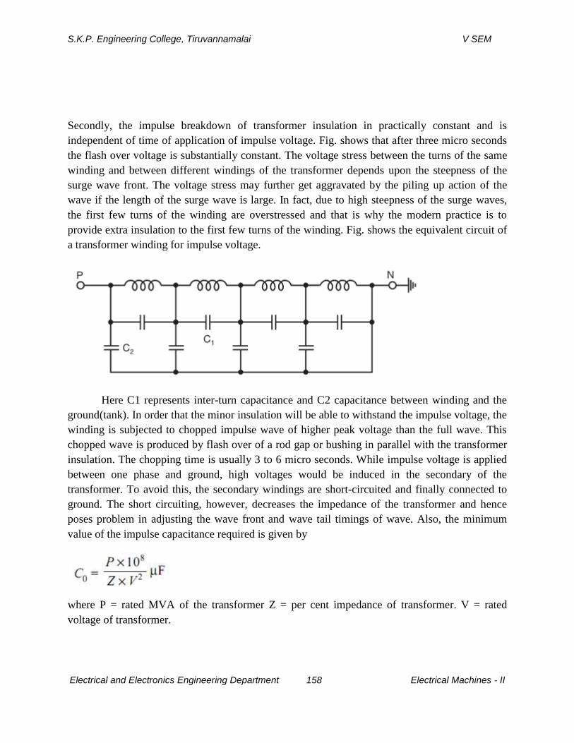
S.K.P. Engineering College, Tiruvannamalai V SEM
Electrical and Electronics Engineering Department 158 Electrical Machines - II
Secondly, the impulse breakdown of transformer insulation in practically constant and is
independent of time of application of impulse voltage. Fig. shows that after three micro seconds
the flash over voltage is substantially constant. The voltage stress between the turns of the same
winding and between different windings of the transformer depends upon the steepness of the
surge wave front. The voltage stress may further get aggravated by the piling up action of the
wave if the length of the surge wave is large. In fact, due to high steepness of the surge waves,
the first few turns of the winding are overstressed and that is why the modern practice is to
provide extra insulation to the first few turns of the winding. Fig. shows the equivalent circuit of
a transformer winding for impulse voltage.
Here C1 represents inter-turn capacitance and C2 capacitance between winding and the
ground(tank). In order that the minor insulation will be able to withstand the impulse voltage, the
winding is subjected to chopped impulse wave of higher peak voltage than the full wave. This
chopped wave is produced by flash over of a rod gap or bushing in parallel with the transformer
insulation. The chopping time is usually 3 to 6 micro seconds. While impulse voltage is applied
between one phase and ground, high voltages would be induced in the secondary of the
transformer. To avoid this, the secondary windings are short-circuited and finally connected to
ground. The short circuiting, however, decreases the impedance of the transformer and hence
poses problem in adjusting the wave front and wave tail timings of wave. Also, the minimum
value of the impulse capacitance required is given by
where P = rated MVA of the transformer Z = per cent impedance of transformer. V = rated
voltage of transformer.
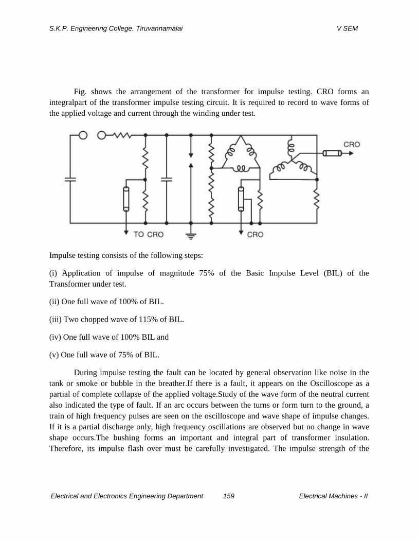
S.K.P. Engineering College, Tiruvannamalai V SEM
Electrical and Electronics Engineering Department 159 Electrical Machines - II
Fig. shows the arrangement of the transformer for impulse testing. CRO forms an
integralpart of the transformer impulse testing circuit. It is required to record to wave forms of
the applied voltage and current through the winding under test.
Impulse testing consists of the following steps:
(i) Application of impulse of magnitude 75% of the Basic Impulse Level (BIL) of the
Transformer under test.
(ii) One full wave of 100% of BIL.
(iii) Two chopped wave of 115% of BIL.
(iv) One full wave of 100% BIL and
(v) One full wave of 75% of BIL.
During impulse testing the fault can be located by general observation like noise in the
tank or smoke or bubble in the breather.If there is a fault, it appears on the Oscilloscope as a
partial of complete collapse of the applied voltage.Study of the wave form of the neutral current
also indicated the type of fault. If an arc occurs between the turns or form turn to the ground, a
train of high frequency pulses are seen on the oscilloscope and wave shape of impulse changes.
If it is a partial discharge only, high frequency oscillations are observed but no change in wave
shape occurs.The bushing forms an important and integral part of transformer insulation.
Therefore, its impulse flash over must be carefully investigated. The impulse strength of the
S.K.P. Engineering College, Tiruvannamalai V SEM
Electrical and Electronics Engineering Department 160 Electrical Machines - II
transformer winding is same for either polarity of wave whereas the flash over voltage for
bushing is different for different polarity. The manufacturer, however, while specifying the
impulse strength of the transformer takes into consideration the overall impulse characteristic of
the transformer.
6.Discuss the various tests carried out in a circuit breaker at HV lab? (CO5-L1-MAY2013)
TESTING OF CIRCUIT BREAKERS
An equipment when designed to certain specification and is fabricated, needs testing for
its performance. The general design is tried and the results of such tests conducted on one
selected breaker and are thus applicable to all others of identical construction. These tests are
called the type tests. These tests are classified as follows:
1. Short circuit tests:
(i) Making capacity test.
(ii) Breaking capacity test.
(iii) Short time current test.
(iv)Operating duty test
2. Dielectric tests:
(i) Power frequency test:
(a) One minute dry withstand test.
(b) One minute wet withstand test.
(ii) Impulse voltage dry withstand test.
3. Thermal test.
4. Mechanical test
S.K.P. Engineering College, Tiruvannamalai V SEM
Electrical and Electronics Engineering Department 161 Electrical Machines - II
Once a particular design is found satisfactory, a large number of similar C.Bs. are manufactured
for marketing. Every piece of C.B. is then tested before putting into service. These tests are
known as routine tests. With these tests it is possible to find out if incorrect assembly or inferior
quality materialh as been used for a proven design equipment. These tests are classified as
(i) operation tests,
(ii) millivolt drop tests,
(iii)power frequency voltage tests at manufacturer’s premises, and
(iv) power frequency voltage tests after erection on site.
We will discuss first the type tests. In that also we will discuss the short circuit tests after the
other three tests.
Dielectric Tests
The general dielectric characteristics of any circuit breaker or switchgear unit depend upon the
basic design i.e. clearances, bushing materials, etc. upon correctness and accuracy in assembly
and upon the quality of materials used. For a C.B. these factors are checked from the viewpoint
of their ability to withstand over voltages at the normal service voltage and abnormal voltages
during lightning or other phenomenon.
The test voltage is applied for a period of one minute between
(i) phases with the breaker closed,(ii) phases and earth with C.B. open, and across the terminals
with breaker open. With this the breaker must not flash over or puncture. These tests are
normally made on indoor switchgear. For such C.Bs the impulse tests generally are unnecessary
because it is not exposed to impulse voltage of a very high order. The high frequency switching
surges do occur but the effect of these in cable systems used for indoor switchgear are found to
be safely withstood by the switchgear if it has withstood the normal frequency test.Since the
outdoor switchgear is electrically exposed, they will be subjected to over voltages caused by
lightning. The effect of these voltages is much more serious than the power frequency voltages
in service. Therefore, this class of switchgear is subjected in addition to power frequency tests,
the impulse voltage tests.The test voltage should be a standard 1/50 µ sec wave, the peak value
of which is specified according to the rated voltage of the breaker. A higher impulse voltage is
S.K.P. Engineering College, Tiruvannamalai V SEM
Electrical and Electronics Engineering Department 162 Electrical Machines - II
specified for non-effectively grounded system than those for solidly grounded system. The test
voltages are applied between (i) each pole and earth in turn with the breaker closed and
remaining phases earthed, and (ii) between all terminals on one side of the breaker and all the
other terminals earthed, with the breaker open. The specified voltages are withstand values i.e.
the breaker should not flash over for 10 applications of the wave.Normally this test is carried out
with waves of both the polarities.The wet dielectric test is used for outdoor switchgear. In this,
the external insulation is sprayed for two minutes while the rated service voltage is applied; the
test overvoltage is then maintained for30 seconds during which no flash over should occur. The
effect of rain on external insulation is partly beneficial, insofar as the surface is thereby cleaned,
but is also harmful if the rain contains impurities.
Thermal Tests
These tests are made to check the thermal behaviour of the breakers. In this test the rated current
through all three phases of the switchgear is passed continuously for a period long enough to
achieve steady state conditions. Temperature readings are obtained by means of thermocouples
whose hot junctions are placed in appropriate positions. The temperature rise above ambient, of
conductors, must normally not exceed 40°C when the rated normal current is less than 800 amps
and 50°C if it is 800amps and above.An additional requirement in the type test is the
measurement of the contact resistances between the isolating contacts and between the moving
and fixed contacts. These points are generally the main sources of excessive heat generation. The
voltage drop across the breaker pole is measured for different values of d.c. current which is a
measure of the resistance of current carrying parts and hence that of contacts.
Mechanical Tests
A C.B. must open and close at the correct speed and perform such operations without
mechanical failure. The breaker mechanism is, therefore, subjected to a mechanical endurance
type test involving repeated opening and closing of the breaker. B.S. 116: 1952 requires 500 such
operations without failure and with no adjustment of the mechanism. Some manufacture feel that
as many as 20,000operations may be reached before any useful information regarding the
S.K.P. Engineering College, Tiruvannamalai V SEM
Electrical and Electronics Engineering Department 163 Electrical Machines - II
possible causes of failure maybe obtained. A resulting change in the material or dimensions of a
particular component may considerably improve the life and efficiency of the mechanism.
Short Circuit Tests
These tests are carried out in short circuit testing stations to prove the ratings of the C.Bs. Before
discussing the tests it is proper to discuss about the short circuit testing stations.There are two
types of testing stations; (i) field type, and (ii) laboratory type.In case of field type stations the
power required for testing is directly taken from a large powersystem. The breaker to be tested is
connected to the system. Whereas this method of testing is economical for high voltage C.Bs. it
suffers from the following drawbacks:
1. The tests cannot be repeatedly carried out for research and development as it disturbs the
whole network.
2. The power available depends upon the location of the testing stations, loading
conditions,installed capacity, etc.
3. Test conditions like the desired recovery voltage, the RRRV etc. cannot be achieved con-
veniently.In case of laboratory testing the power required for testing is provided by specially
designed generators. This method has the following advantages:
1. Test conditions such as current, voltage, power factor, restriking voltages can be controlled
accurately.
2. Several indirect testing methods can be used.
3. Tests can be repeated and hence research and development over the design is possible.The
limitations of this method are the cost and the limited power availability for testing the breakers.
Short Circuit Test Plants
The essential components of a typical test plant are represented in Fig. 5.4. The short-
circuit power is supplied by specially designed short-circuit generators driven by induction
motors. The magnitude of voltage can be varied by adjusting excitation of the generator or the
transformer ratio. A plant master-breaker is available to interrupt the test short circuit current if
the test breaker should fail. Initiation of the short circuit may be by the master breaker, but is
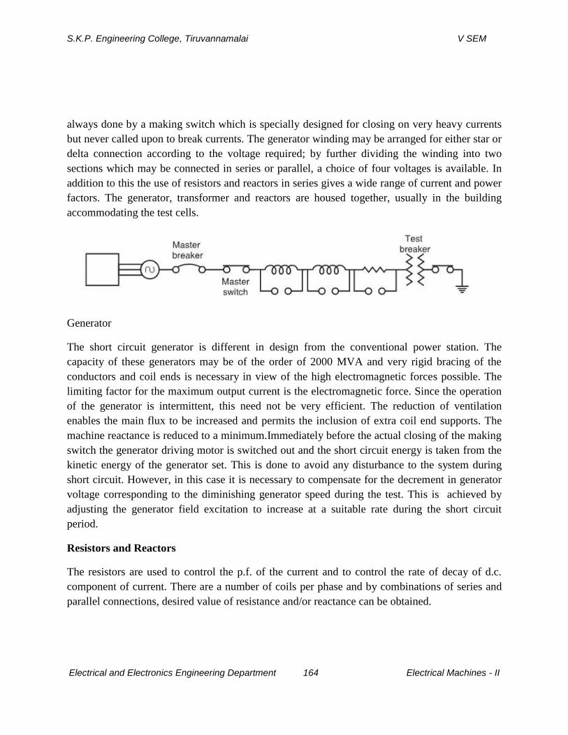
S.K.P. Engineering College, Tiruvannamalai V SEM
Electrical and Electronics Engineering Department 164 Electrical Machines - II
always done by a making switch which is specially designed for closing on very heavy currents
but never called upon to break currents. The generator winding may be arranged for either star or
delta connection according to the voltage required; by further dividing the winding into two
sections which may be connected in series or parallel, a choice of four voltages is available. In
addition to this the use of resistors and reactors in series gives a wide range of current and power
factors. The generator, transformer and reactors are housed together, usually in the building
accommodating the test cells.
Generator
The short circuit generator is different in design from the conventional power station. The
capacity of these generators may be of the order of 2000 MVA and very rigid bracing of the
conductors and coil ends is necessary in view of the high electromagnetic forces possible. The
limiting factor for the maximum output current is the electromagnetic force. Since the operation
of the generator is intermittent, this need not be very efficient. The reduction of ventilation
enables the main flux to be increased and permits the inclusion of extra coil end supports. The
machine reactance is reduced to a minimum.Immediately before the actual closing of the making
switch the generator driving motor is switched out and the short circuit energy is taken from the
kinetic energy of the generator set. This is done to avoid any disturbance to the system during
short circuit. However, in this case it is necessary to compensate for the decrement in generator
voltage corresponding to the diminishing generator speed during the test. This is achieved by
adjusting the generator field excitation to increase at a suitable rate during the short circuit
period.
Resistors and Reactors
The resistors are used to control the p.f. of the current and to control the rate of decay of d.c.
component of current. There are a number of coils per phase and by combinations of series and
parallel connections, desired value of resistance and/or reactance can be obtained.
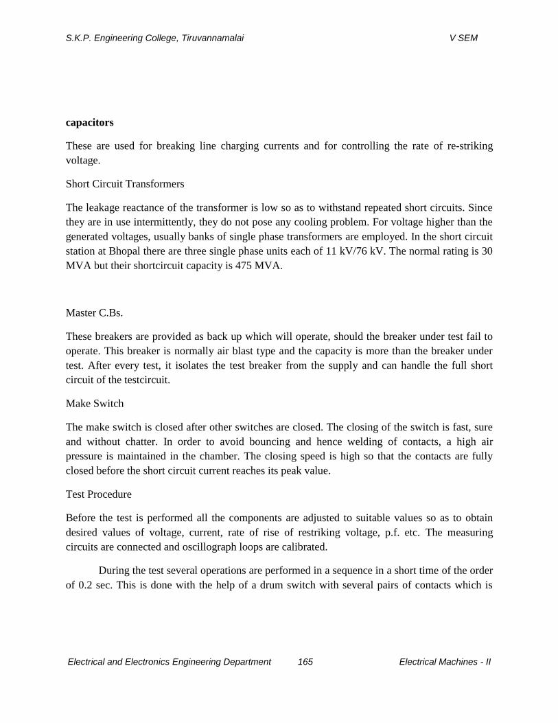
S.K.P. Engineering College, Tiruvannamalai V SEM
Electrical and Electronics Engineering Department 165 Electrical Machines - II
capacitors
These are used for breaking line charging currents and for controlling the rate of re-striking
voltage.
Short Circuit Transformers
The leakage reactance of the transformer is low so as to withstand repeated short circuits. Since
they are in use intermittently, they do not pose any cooling problem. For voltage higher than the
generated voltages, usually banks of single phase transformers are employed. In the short circuit
station at Bhopal there are three single phase units each of 11 kV/76 kV. The normal rating is 30
MVA but their shortcircuit capacity is 475 MVA.
Master C.Bs.
These breakers are provided as back up which will operate, should the breaker under test fail to
operate. This breaker is normally air blast type and the capacity is more than the breaker under
test. After every test, it isolates the test breaker from the supply and can handle the full short
circuit of the testcircuit.
Make Switch
The make switch is closed after other switches are closed. The closing of the switch is fast, sure
and without chatter. In order to avoid bouncing and hence welding of contacts, a high air
pressure is maintained in the chamber. The closing speed is high so that the contacts are fully
closed before the short circuit current reaches its peak value.
Test Procedure
Before the test is performed all the components are adjusted to suitable values so as to obtain
desired values of voltage, current, rate of rise of restriking voltage, p.f. etc. The measuring
circuits are connected and oscillograph loops are calibrated.
During the test several operations are performed in a sequence in a short time of the order
of 0.2 sec. This is done with the help of a drum switch with several pairs of contacts which is
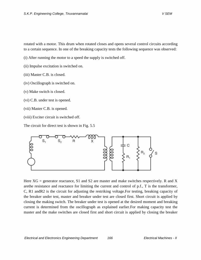
S.K.P. Engineering College, Tiruvannamalai V SEM
Electrical and Electronics Engineering Department 166 Electrical Machines - II
rotated with a motor. This drum when rotated closes and opens several control circuits according
to a certain sequence. In one of the breaking capacity tests the following sequence was observed:
(i) After running the motor to a speed the supply is switched off.
(ii) Impulse excitation is switched on.
(iii) Master C.B. is closed.
(iv) Oscillograph is switched on.
(v) Make switch is closed.
(vi) C.B. under test is opened.
(vii) Master C.B. is opened.
(viii) Exciter circuit is switched off.
The circuit for direct test is shown in Fig. 5.5
Here XG = generator reactance, S1 and S2 are master and make switches respectively. R and X
arethe resistance and reactance for limiting the current and control of p.f., T is the transformer,
C, R1 andR2 is the circuit for adjusting the restriking voltage.For testing, breaking capacity of
the breaker under test, master and breaker under test are closed first. Short circuit is applied by
closing the making switch. The breaker under test is opened at the desired moment and breaking
current is determined from the oscillograph as explained earlier.For making capacity test the
master and the make switches are closed first and short circuit is applied by closing the breaker
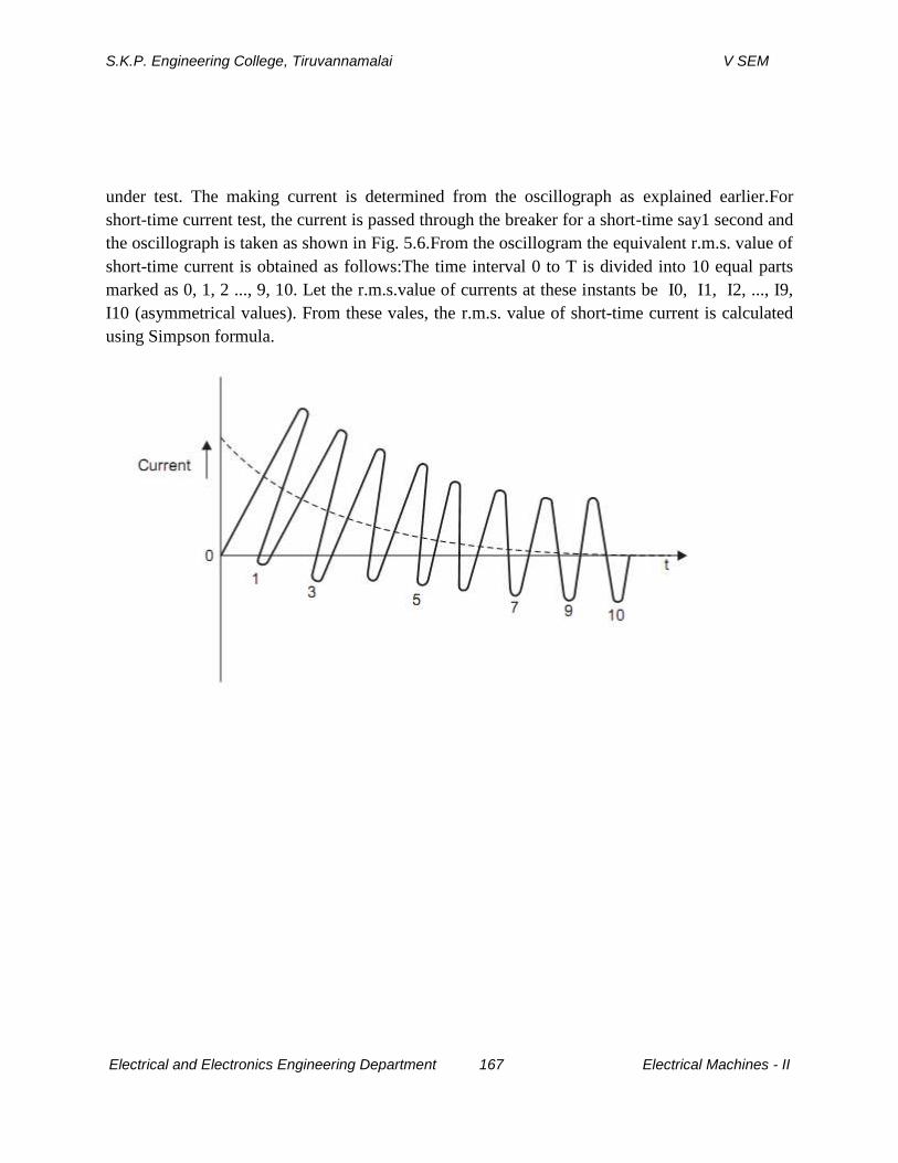
S.K.P. Engineering College, Tiruvannamalai V SEM
Electrical and Electronics Engineering Department 167 Electrical Machines - II
under test. The making current is determined from the oscillograph as explained earlier.For
short-time current test, the current is passed through the breaker for a short-time say1 second and
the oscillograph is taken as shown in Fig. 5.6.From the oscillogram the equivalent r.m.s. value of
short-time current is obtained as follows:The time interval 0 to T is divided into 10 equal parts
marked as 0, 1, 2 ..., 9, 10. Let the r.m.s.value of currents at these instants be I0, I1, I2, ..., I9,
I10 (asymmetrical values). From these vales, the r.m.s. value of short-time current is calculated
using Simpson formula.
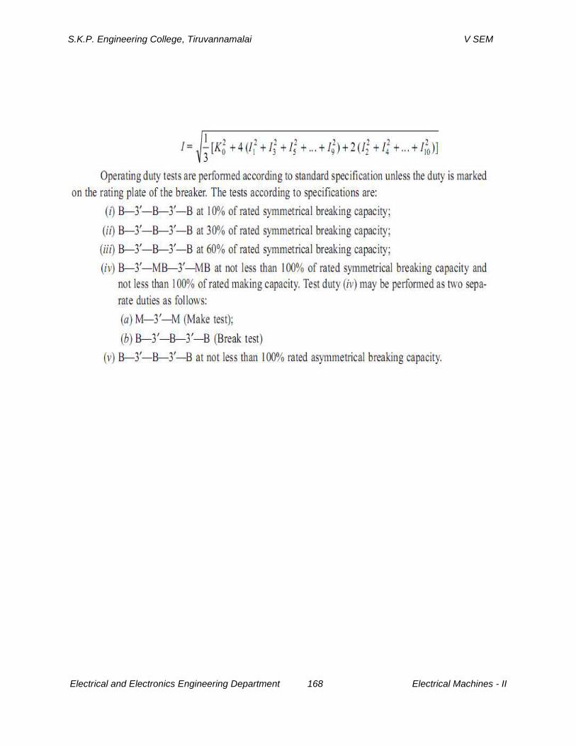
S.K.P. Engineering College, Tiruvannamalai V SEM
Electrical and Electronics Engineering Department 168 Electrical Machines - II