sk tech co., ltd. report/pr_1_04_ko_off___trium_sh5016_ce.pdf · sk tech co., ltd. page 2 of 66...
TRANSCRIPT
SK TECH CO., LTD. Page 2 of 66
SKTCEE-090820-152-A2
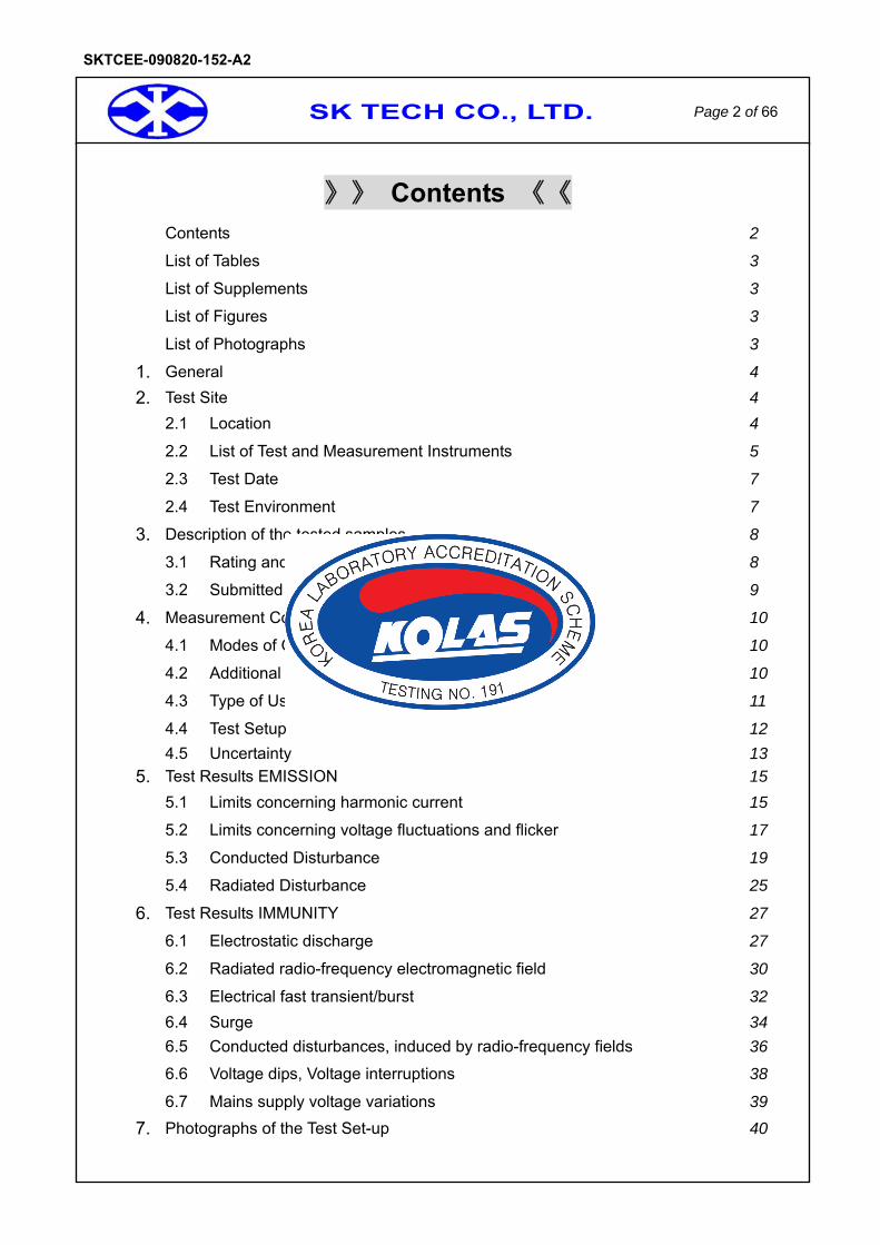
》》 Contents 《《 Contents 2
List of Tables 3
List of Supplements 3
List of Figures 3
List of Photographs 3
1. General 4 2. Test Site 4
2.1 Location 4
2.2 List of Test and Measurement Instruments 5
2.3 Test Date 7
2.4 Test Environment 7
3. Description of the tested samples 8
3.1 Rating and Physical Characteristics 8
3.2 Submitted Documents 9
4. Measurement Conditions 10
4.1 Modes of Operation 10
4.2 Additional Equipment 10
4.3 Type of Used Cables 11
4.4 Test Setup 12 4.5 Uncertainty 13
5. Test Results EMISSION 15 5.1 Limits concerning harmonic current 15
5.2 Limits concerning voltage fluctuations and flicker 17
5.3 Conducted Disturbance 19
5.4 Radiated Disturbance 25
6. Test Results IMMUNITY 27
6.1 Electrostatic discharge 27
6.2 Radiated radio-frequency electromagnetic field 30
6.3 Electrical fast transient/burst 32 6.4 Surge 34 6.5 Conducted disturbances, induced by radio-frequency fields 36
6.6 Voltage dips, Voltage interruptions 38
6.7 Mains supply voltage variations 39
7. Photographs of the Test Set-up 40
SK TECH CO., LTD. Page 3 of 66
SKTCEE-090820-152-A2
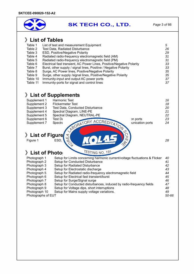
》List of Tables Table 1 List of test and measurement Equipment 5 Table 2 Test Data, Radiated Disturbance 26Table 3 ESD, Positive/Negative Polarity 29Table 4 Radiated radio-frequency electromagnetic field (AM) 31Table 5 Radiated radio-frequency electromagnetic field (PM) 31Table 6 Electrical fast transient, AC Power Lines, Positive/Negative Polarity 33Table 7 Burst, other supply / signal lines, Positive / Negative Polarity 33Table 8 Surge, AC Power lines, Positive/Negative Polarity 35Table 9 Surge, other supply /signal lines, Positive/Negative Polarity 35Table 10 Immunity-input and output AC power ports 37Table 11 Immunity-ports for signal and control lines 37
》List of Supplements Supplement 1 Harmonic Test 16Supplement 2 Flickermeter Test 18Supplement 3 Test Data, Conducted Disturbance 20Supplement 4 Spectral Diagram, LINE-PE 21Supplement 5 Spectral Diagram, NEUTRAL-PE 22Supplement 6 Test Data, Conducted Disturbance at telecommunication ports 23Supplement 7 Spectral Diagram, conducted Disturbance at telecommunication ports 24
》List of Figures Figure 1 ESD, Discharged points 28
》List of Photographs Photograph 1 Setup for Limits concerning harmonic current/voltage fluctuations & Flicker 40 Photograph 2 Setup for Conducted Disturbance 41 Photograph 3 Setup for Radiated Disturbance 42 Photograph 4 Setup for Electrostatic discharge 43 Photograph 5 Setup for Radiated radio-frequency electromagnetic field 44 Photograph 6 Setup for Electrical fast transient/burst 45 Photograph 7 Setup for Surge/Signal surge 46 Photograph 8 Setup for Conducted disturbances, induced by radio-frequency fields 47 Photograph 9 Setup for Voltage dips, short interruptions 48 Photograph 10 Setup for Mains supply voltage variations. 49 Photographs of EUT 50-66
SK TECH CO., LTD. Page 4 of 66
SKTCEE-090820-152-A2
1. General This equipment has been shown to be capable of compliance with the applicable technical standards and was tested in accordance with the measurement procedures as indicated in this report. We attest to the accuracy of data. All measurements reported herein were performed by SK TECH Co., Ltd. and were made under Chief Engineer’s supervision. We assume full responsibility for the completeness of these measurements and vouch for the qualifications of all persons taking them.
2. Test Site
SK TECH Co., Ltd.
2.1 Location 820-2, Wolmoon Ri, Wabu-Up, Namyangju-Si, Kyunggi-Do, Korea
The test site is in compliance with ISO/IEC 17025 for general requirements for the competence of testing and calibration laboratories. This laboratory is recognized as a Conformity Assessment Body(CAB) for CAB’s Designation Number: KR0007 by FCC, is accredited by NVLAP for NVLAP Lab. Code : 200220-0 and DATech for DAR-Registration No.:DAT-P-076/97-02 and KOLAS for Accreditation No.:KT191.

SK TECH CO., LTD. Page 5 of 66
SKTCEE-090820-152-A2
2.2 List of Test and Measurement Instruments
Table 1 : List of Test and Measurement Equipment
•Conducted Disturbance Kind of Equipment Type S/N Calibrated until
EMI Receiver ESHS10 862970/019 07.2010 Artificial Mains Network ESH2-Z5 834549/011 07.2010 Artificial Mains Network ESH3-Z5 836679/018 07.2010
Impedance Stabilization Network ISN T8 24806 09.2009
•Radiated Disturbance Kind of Equipment Type S/N Calibrated until
EMI Receiver ESVS10 834468/008 07.2010 Amplifier 8447F 3113A05153 07.2010
Trilog-Broadband Antenna VULB9168 9168-230 07.2010 Antenna Turntable Driver 5907 91X518 N/A
Antenna Turntable controller 5906 91X519 N/A EMI TEST RECEIVER ESPI 101206 07.2010
•Limits concerning Harmonic Current / Voltage Fluctuations and Flicker Kind of Equipment Type S/N Calibrated until
Reference Impedance Network IMP555 IG147/1172 07.2010
Universal Power Analyzer PM 6000 100006700207 12.2009
•EN 61000-4-2 (Electrostatic discharge) Kind of Equipment Type S/N Calibrated until
ESD simulator ESS-2000AX ESS0898782 06.2010

SK TECH CO., LTD. Page 6 of 66
SKTCEE-090820-152-A2
•EN 61000-4-3 (Radiated radio-frequency electromagnetic field)
Kind of Equipment Type S/N Calibrated until Wideband Amplifier CMX10001 1045-0995 N/A Wideband Amplifier SMCC100 1047-0995 N/A Wideband Amplifier M5300 1046-0995 N/A Signal Generator SMY01 71400091 03.2010
Power Meter NRVD 100496 07.2010 10V Insertion Unit URV5-Z2 100166 07.2010 10V Insertion Unit URV5-Z2 100167 07.2010
High Gain Log Periodic Antenna HL046 100032 N/A Signal Generator SML03 100801 07.2010
Power Meter NRVD 100495 07.2010 Function Generator 33120A MY40019927 07.2010 10V Insertion Unit URV5-Z2 100164 07.2010 10V Insertion Unit URV5-Z2 100165 07.2010
RF Power Amplifier FLG-50C N/A N/A RF Power Amplifier FLH-200/100 N/A N/A
Switch unit GTS1003 1287 N/A Octave Bandwidth
Pyramidal Horn Antenna (1G~2G)
3161-01 00032184 N/A
•EN 61000-4-4 (Electrical fast transient/burst)
Kind of Equipment Type S/N Calibrated until
Ultra Compact Simulator UCS 500 M6B V0545100862 07.2010
Motor Variac MV 2610 V0545100863 N/A Capacitive
Coupling Clamp HFK 1205-11 07.2010
•EN 61000-4-5 (Surge)
Kind of Equipment Type S/N Calibrated until I/O Signal
Line Coupler/Decoupler CM-I/OCD 0005192 N/A
Ultra Compact Simulator UCS 500 M6B V0545100862 07.2010
Motor Variac MV 2610 V0545100863 N/A
SK TECH CO., LTD. Page 7 of 66
SKTCEE-090820-152-A2
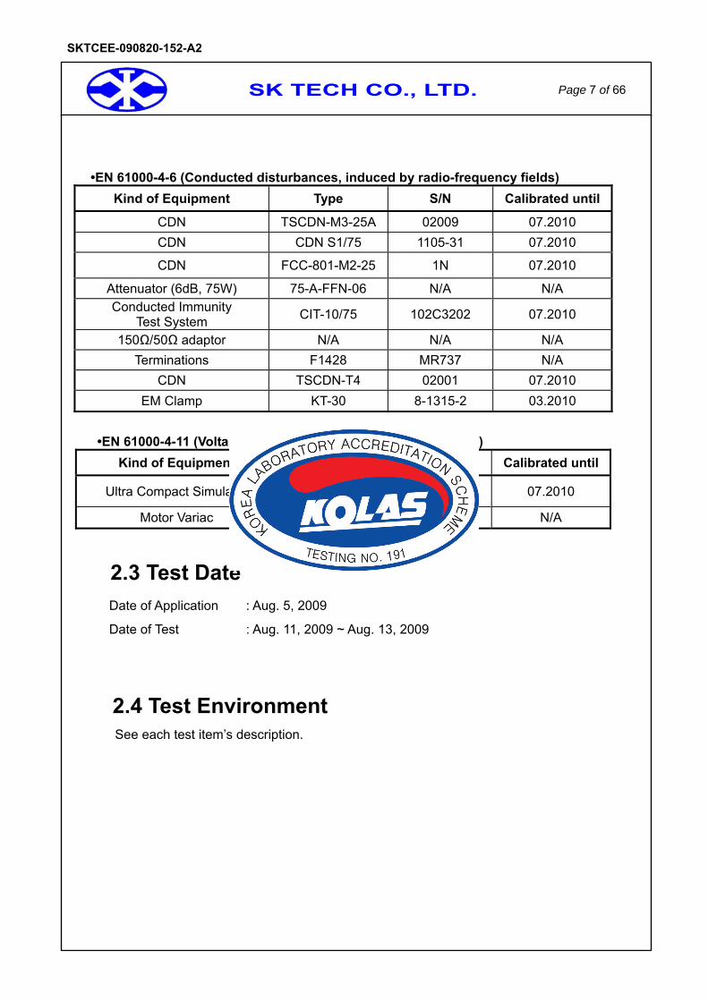
•EN 61000-4-6 (Conducted disturbances, induced by radio-frequency fields)
Kind of Equipment Type S/N Calibrated until
CDN TSCDN-M3-25A 02009 07.2010 CDN CDN S1/75 1105-31 07.2010
CDN FCC-801-M2-25 1N 07.2010
Attenuator (6dB, 75W) 75-A-FFN-06 N/A N/A Conducted Immunity
Test System CIT-10/75 102C3202 07.2010
150Ω/50Ω adaptor N/A N/A N/A Terminations F1428 MR737 N/A
CDN TSCDN-T4 02001 07.2010 EM Clamp KT-30 8-1315-2 03.2010
•EN 61000-4-11 (Voltage dips, Mains supply voltage variations)
Kind of Equipment Type S/N Calibrated until
Ultra Compact Simulator UCS 500 M6B V0545100862 07.2010
Motor Variac MV 2610 V0545100863 N/A
2.3 Test Date Date of Application : Aug. 5, 2009
Date of Test : Aug. 11, 2009 ~ Aug. 13, 2009
2.4 Test Environment See each test item’s description.
SK TECH CO., LTD. Page 8 of 66
SKTCEE-090820-152-A2
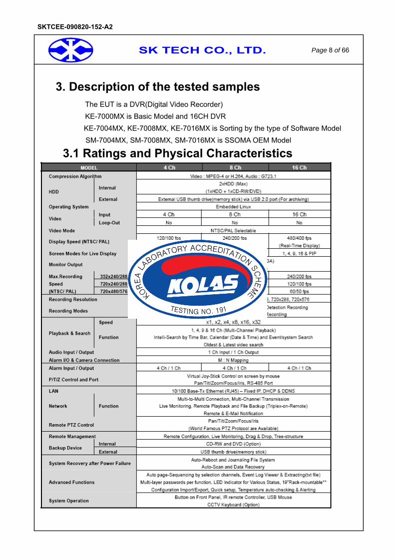
3. Description of the tested samples The EUT is a DVR(Digital Video Recorder) KE-7000MX is Basic Model and 16CH DVR KE-7004MX, KE-7008MX, KE-7016MX is Sorting by the type of Software Model
SM-7004MX, SM-7008MX, SM-7016MX is SSOMA OEM Model
3.1 Ratings and Physical Characteristics

SK TECH CO., LTD. Page 9 of 66
SKTCEE-090820-152-A2
3.2 Submitted Documents -N/A
SK TECH CO., LTD. Page 10 of 66
SKTCEE-090820-152-A2
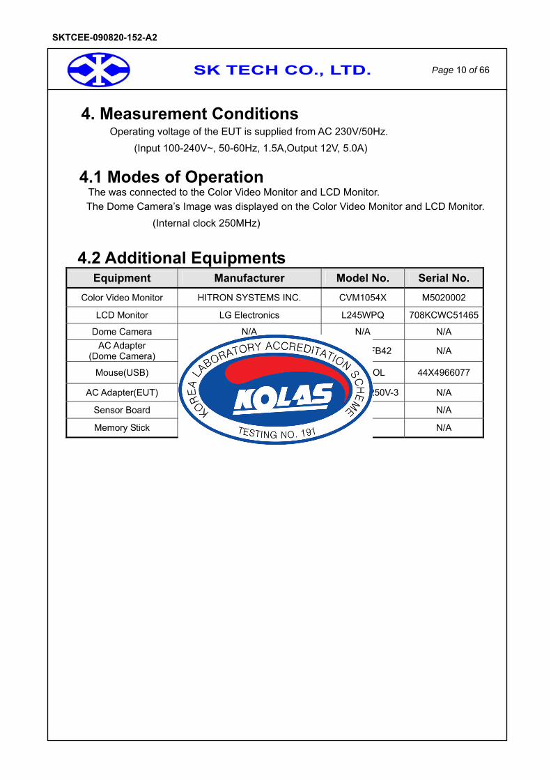
4. Measurement Conditions Operating voltage of the EUT is supplied from AC 230V/50Hz.
(Input 100-240V~, 50-60Hz, 1.5A,Output 12V, 5.0A)
4.1 Modes of Operation The was connected to the Color Video Monitor and LCD Monitor. The Dome Camera’s Image was displayed on the Color Video Monitor and LCD Monitor.
(Internal clock 250MHz)
4.2 Additional Equipments Equipment Manufacturer Model No. Serial No.
Color Video Monitor HITRON SYSTEMS INC. CVM1054X M5020002
LCD Monitor LG Electronics L245WPQ 708KCWC51465
Dome Camera N/A N/A N/A AC Adapter
(Dome Camera) HUA JUNG COMP.CO., LTD. HASU11FB42 N/A
Mouse(USB) DONGGUAN PRIMAX ELECTRONICS LTD MO28UOL 44X4966077
AC Adapter(EUT) Sino-American SA165A-1250V-3 N/A
Sensor Board N/A N/A N/A
Memory Stick N/A N/A N/A
SK TECH CO., LTD. Page 11 of 66
SKTCEE-090820-152-A2
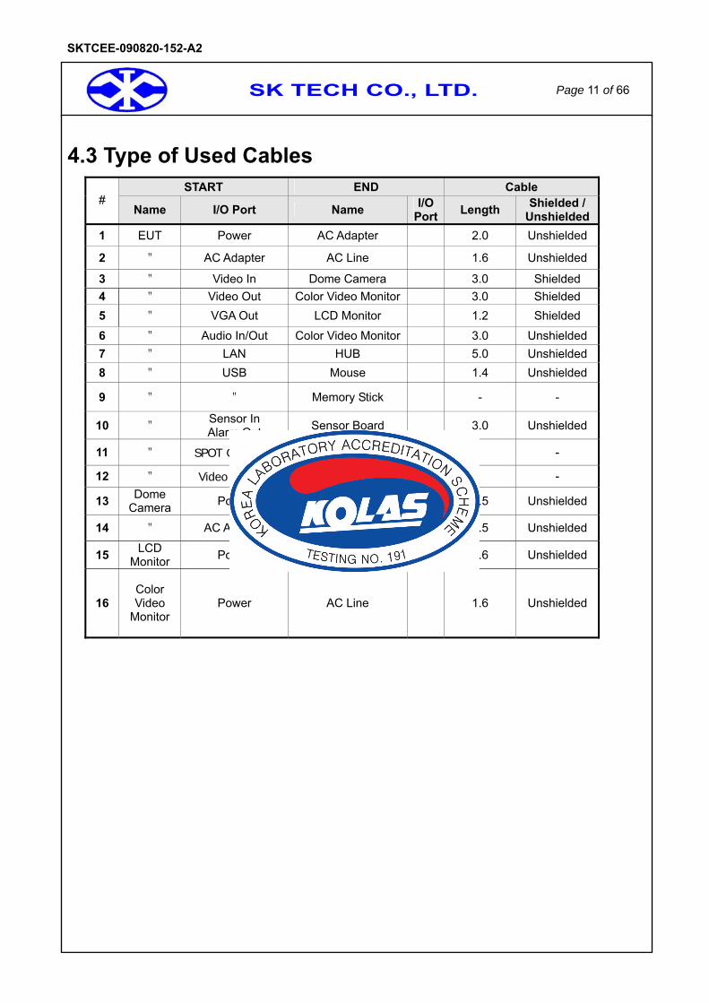
4.3 Type of Used Cables
START END Cable #
Name I/O Port Name I/O Port Length Shielded /
Unshielded1 EUT Power AC Adapter 2.0 Unshielded
2 " AC Adapter AC Line 1.6 Unshielded
3 " Video In Dome Camera 3.0 Shielded 4 " Video Out Color Video Monitor 3.0 Shielded 5 " VGA Out LCD Monitor 1.2 Shielded
6 " Audio In/Out Color Video Monitor 3.0 Unshielded 7 " LAN HUB 5.0 Unshielded 8 " USB Mouse 1.4 Unshielded
9 " " Memory Stick - -
10 " Sensor In Alarm Out Sensor Board 3.0 Unshielded
11 " SPOT OUT (x1) 75Ω Termination - -
12 " Video In(x15) 75Ω Termination - -
13 Dome Camera Power AC Adapter 1.5 Unshielded
14 " AC Adapter AC Line 1.5 Unshielded
15 LCD Monitor Power AC Line 1.6 Unshielded
16 Color Video
Monitor Power AC Line 1.6 Unshielded

SK TECH CO., LTD. Page 12 of 66
SKTCEE-090820-152-A2
4.4 Test Setup
The test setup photographs (#page 40 ~ 49) showed the external supply connections and interfaces.
``
[ System Block Diagram of Test Configuration ]
VGA OUT
Video In (x15) 75ΩTermination
230V
Color Video
Monitor
Video Out
SENSOR In
ALARM Out
LCD
Monitor
Audio In/Out
MemoryStick
Mouse
USB
Dome Camera
AC
Adapter
AC
Adapter
EUTDVR(Digital Video
Recoreder)
LAN(HUB)
SENSOR Board
SPOT OUT (x1) 75ΩTermination
USB
Video in
SK TECH CO., LTD. Page 13 of 66
SKTCEE-090820-152-A2
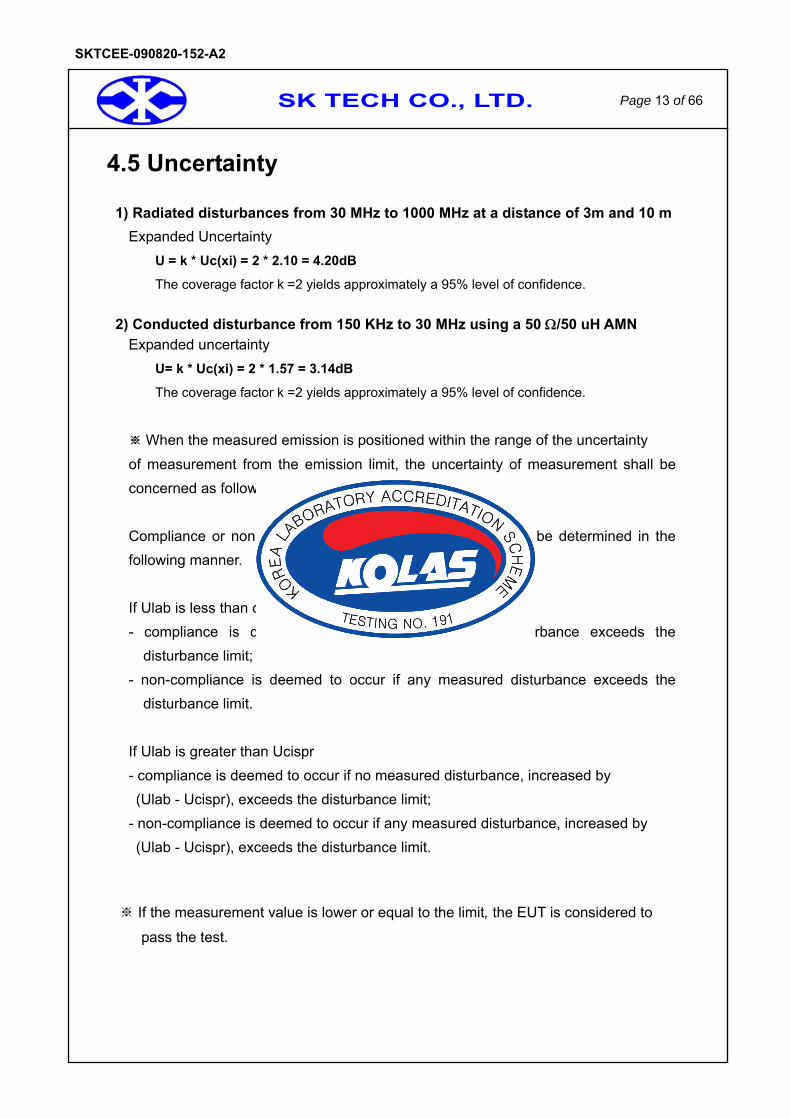
4.5 Uncertainty 1) Radiated disturbances from 30 MHz to 1000 MHz at a distance of 3m and 10 m
Expanded Uncertainty U = k * Uc(xi) = 2 * 2.10 = 4.20dB
The coverage factor k =2 yields approximately a 95% level of confidence.
2) Conducted disturbance from 150 KHz to 30 MHz using a 50 Ω/50 uH AMN Expanded uncertainty
U= k * Uc(xi) = 2 * 1.57 = 3.14dB
The coverage factor k =2 yields approximately a 95% level of confidence.
※ When the measured emission is positioned within the range of the uncertainty of measurement from the emission limit, the uncertainty of measurement shall be concerned as follow. Compliance or non-compliance with a disturbance limit shall be determined in the following manner. If Ulab is less than or equal to Ucispr - compliance is deemed to occur if no measured disturbance exceeds the
disturbance limit; - non-compliance is deemed to occur if any measured disturbance exceeds the
disturbance limit. If Ulab is greater than Ucispr - compliance is deemed to occur if no measured disturbance, increased by (Ulab - Ucispr), exceeds the disturbance limit;
- non-compliance is deemed to occur if any measured disturbance, increased by (Ulab - Ucispr), exceeds the disturbance limit.
If the measurement value is lower or equal to the limit※ , the EUT is considered to
pass the test.

SK TECH CO., LTD. Page 14 of 66
SKTCEE-090820-152-A2
3) EMS UNCERTAINTY All parameters are within the tolerances required by the standard, reduced by the tolerances
required on the calibration certificate, so this laboratory has confidence that the EMS Test
equipment is in compliance with the standard with X% confidence level.
ESD (EN61000-4-2): At least a 95% confidence (k=2)
Radiated immunity (EN61000-4-3): 2.59dB (k=1.64, confidence level is 90%)
EFT (EN61000-4-4): At least a 95% confidence (k=2)
SURGE (EN61000-4-5): At least a 95% confidence (k=2)
Conducted immunity (EN61000-4-6): 1.34dB (k=1.64, confidence level is 90%)
Voltage dip (EN61000-4-11): At least a 95% confidence (k=2)
Reduced by the uncertainty reported
on the calibration certificate.
(about X% confidence level)
Tolerance required by the standard

SK TECH CO., LTD. Page 15 of 66
SKTCEE-090820-152-A2
5. Test Results EMISSION
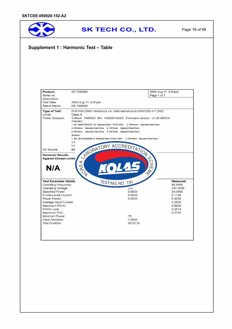
5.1 Limits concerning harmonic current
Result PASS
The harmonics on AC Mains in the frequency from 0 to 2kHz were measured in accordance to EN61000-3-2:2006.
The measurement was conducted with an automatic current harmonic analyzing system. This equipment is in compliance with the requirements of EN61000-3-2:2006. The
Measurement showed that the equipment is classified into class A of EN61000-3-2:2006.
Test Environment Room temperature : 23 Relative Humidity : 52% R.H.
Supplementing the flicker test data to ※ next page.
SK TECH CO., LTD. Page 16 of 66
SKTCEE-090820-152-A2
Supplement 1 : Harmonic Test – Table

SK TECH CO., LTD. Page 17 of 66
SKTCEE-090820-152-A2
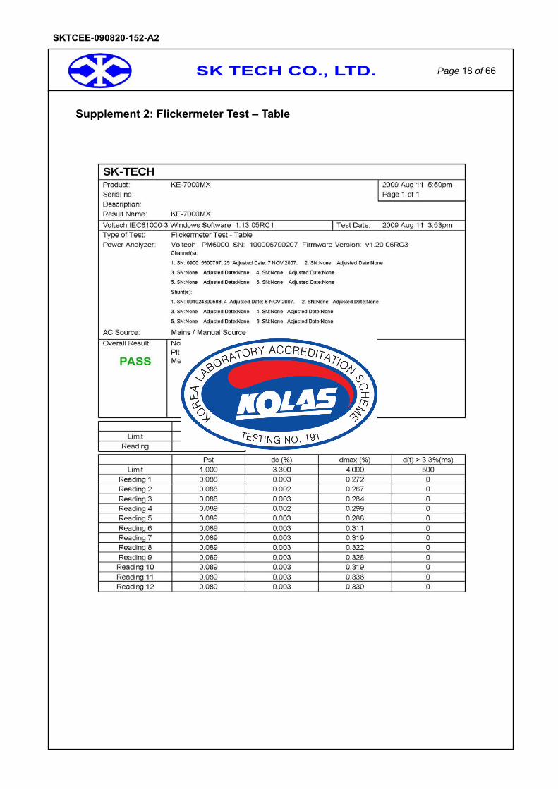
5.2 Limits concerning voltage fluctuations and flicker
Result PASS
The voltage fluctuations on AC mains in the frequency range from 0 to 2kHz were measured in accordance to EN61000-3-3:1995+A1:2001+A2:2005. The measurement was conducted with an automatic current harmonic analyzing system. This equipment is in compliance with the requirements of EN61000-3-3:1995 +A1:2001+A2:2005.
Test Environment Room temperature : 23 Relative Humidity : 50 % R.H.
Supplementing the flicker test data to ※ next page.
SK TECH CO., LTD. Page 18 of 66
SKTCEE-090820-152-A2
Supplement 2: Flickermeter Test – Table
SK TECH CO., LTD. Page 19 of 66
SKTCEE-090820-152-A2
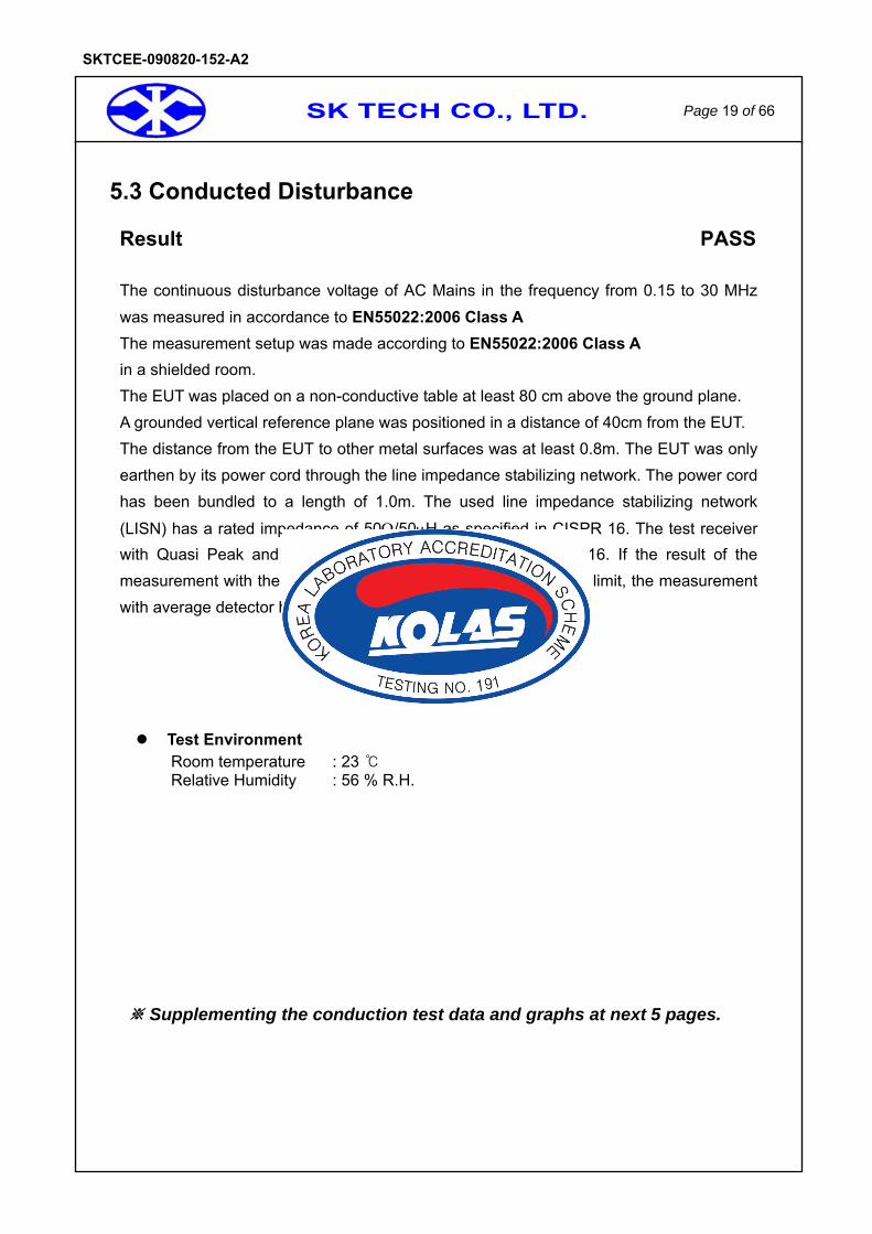
5.3 Conducted Disturbance
Result PASS
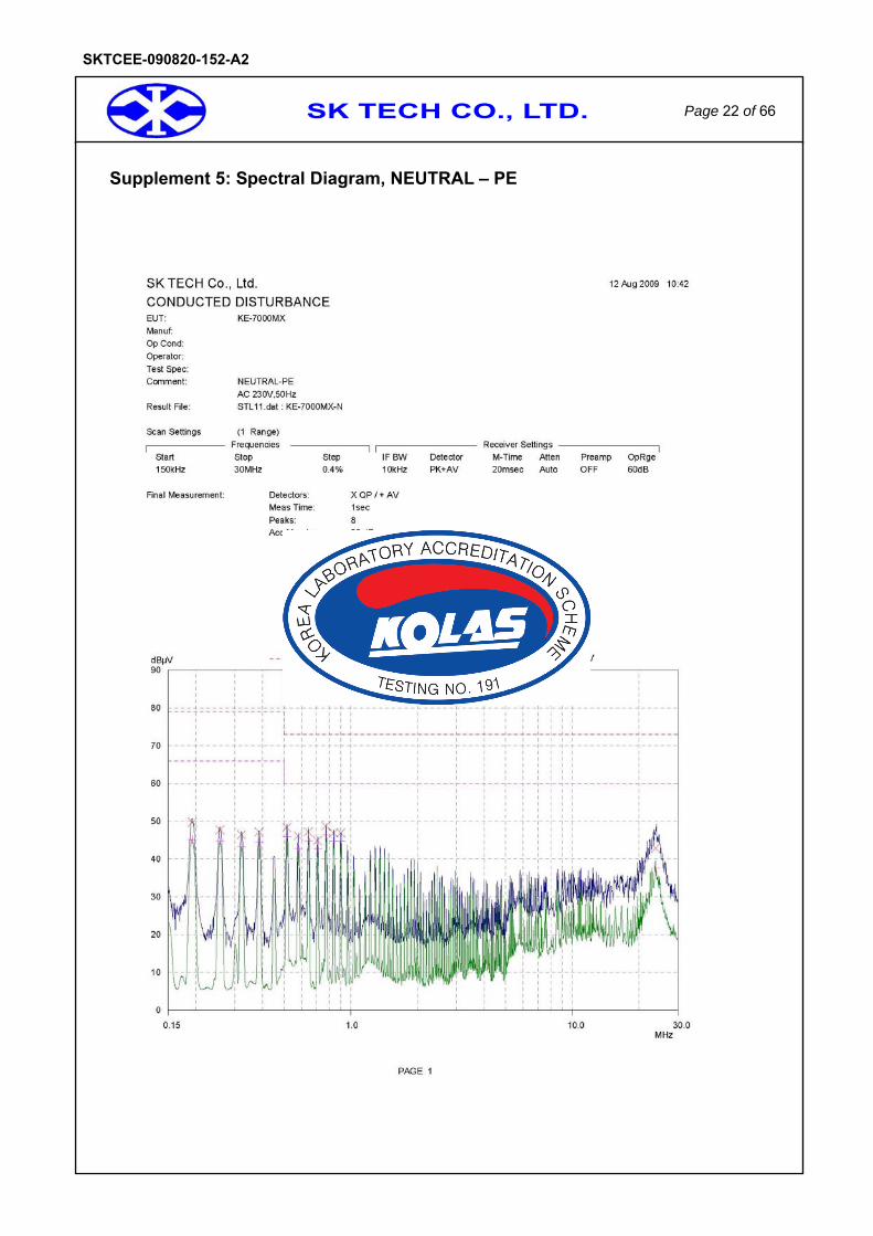
The continuous disturbance voltage of AC Mains in the frequency from 0.15 to 30 MHz was measured in accordance to EN55022:2006 Class A The measurement setup was made according to EN55022:2006 Class A in a shielded room. The EUT was placed on a non-conductive table at least 80 cm above the ground plane. A grounded vertical reference plane was positioned in a distance of 40cm from the EUT. The distance from the EUT to other metal surfaces was at least 0.8m. The EUT was only earthen by its power cord through the line impedance stabilizing network. The power cord has been bundled to a length of 1.0m. The used line impedance stabilizing network
(LISN) has a rated impedance of 50Ω/50μH as specified in CISPR 16. The test receiver with Quasi Peak and Average detector complies with CISPR 16. If the result of the measurement with the Quasi Peak detector is below the average limit, the measurement with average detector has been omitted.
Test Environment Room temperature : 23 Relative Humidity : 56 % R.H.
Supplementing the conduction test data and graphs at next ※ 5 pages.
SK TECH CO., LTD. Page 20 of 66
SKTCEE-090820-152-A2
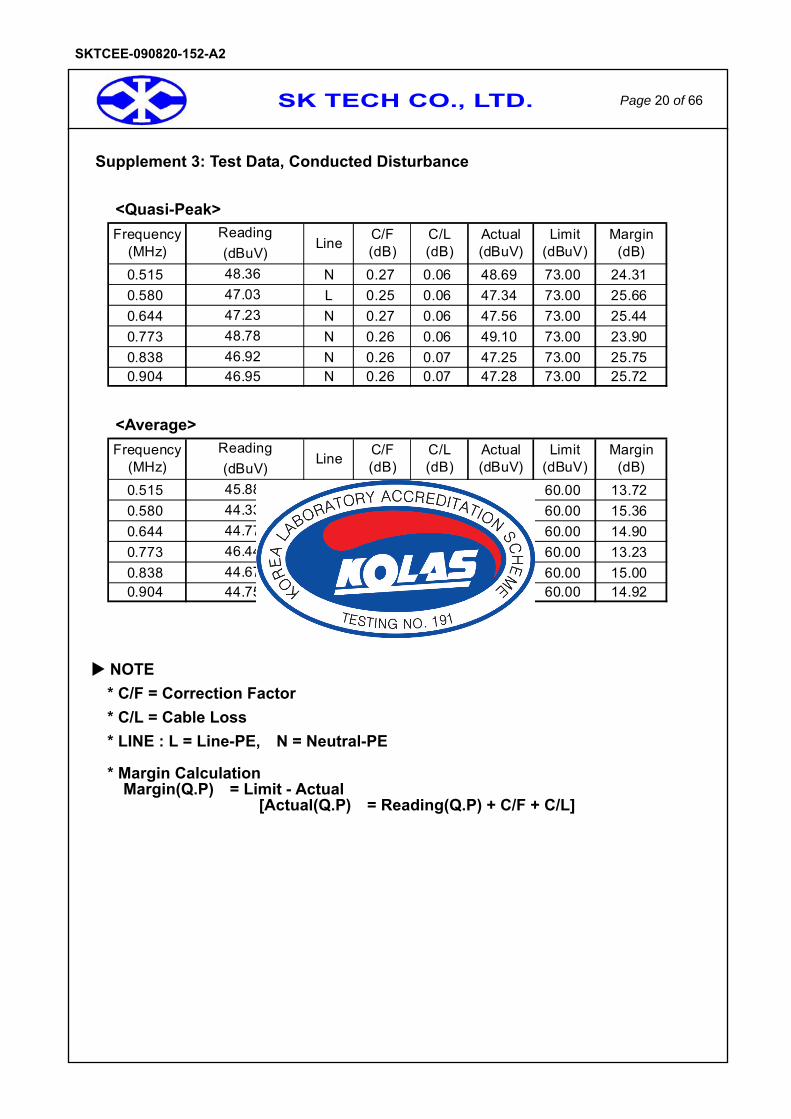
Supplement 3: Test Data, Conducted Disturbance
<Quasi-Peak>
0.515 N 0.27 0.06 48.69 73.00 24.310.580 L 0.25 0.06 47.34 73.00 25.660.644 N 0.27 0.06 47.56 73.00 25.440.773 N 0.26 0.06 49.10 73.00 23.900.838 N 0.26 0.07 47.25 73.00 25.750.904 N 0.26 0.07 47.28 73.00 25.72
C/L(dB)
Actual(dBuV)
Limit(dBuV)
Margin(dB)
Frequency(MHz)
ReadingLine C/F
(dB)(dBuV)
46.9246.95
48.3647.0347.2348.78
<Average>
0.515 N 0.35 0.05 46.28 60.00 13.720.580 L 0.25 0.06 44.64 60.00 15.360.644 N 0.27 0.06 45.10 60.00 14.900.773 N 0.26 0.07 46.77 60.00 13.230.838 N 0.26 0.07 45.00 60.00 15.000.904 N 0.26 0.07 45.08 60.00 14.92
44.6744.75
45.8844.3344.7746.44
Frequency(MHz)
ReadingLine C/F
(dB)(dBuV)C/L(dB)
Actual(dBuV)
Limit(dBuV)
Margin(dB)
NOTE * C/F = Correction Factor * C/L = Cable Loss * LINE : L = Line-PE, N = Neutral-PE
* Margin Calculation Margin(Q.P) = Limit - Actual
[Actual(Q.P) = Reading(Q.P) + C/F + C/L]

SK TECH CO., LTD. Page 21 of 66
SKTCEE-090820-152-A2
Supplement 4: Spectral Diagram, LINE – PE
SK TECH CO., LTD. Page 22 of 66
SKTCEE-090820-152-A2
Supplement 5: Spectral Diagram, NEUTRAL – PE
SK TECH CO., LTD. Page 23 of 66
SKTCEE-090820-152-A2
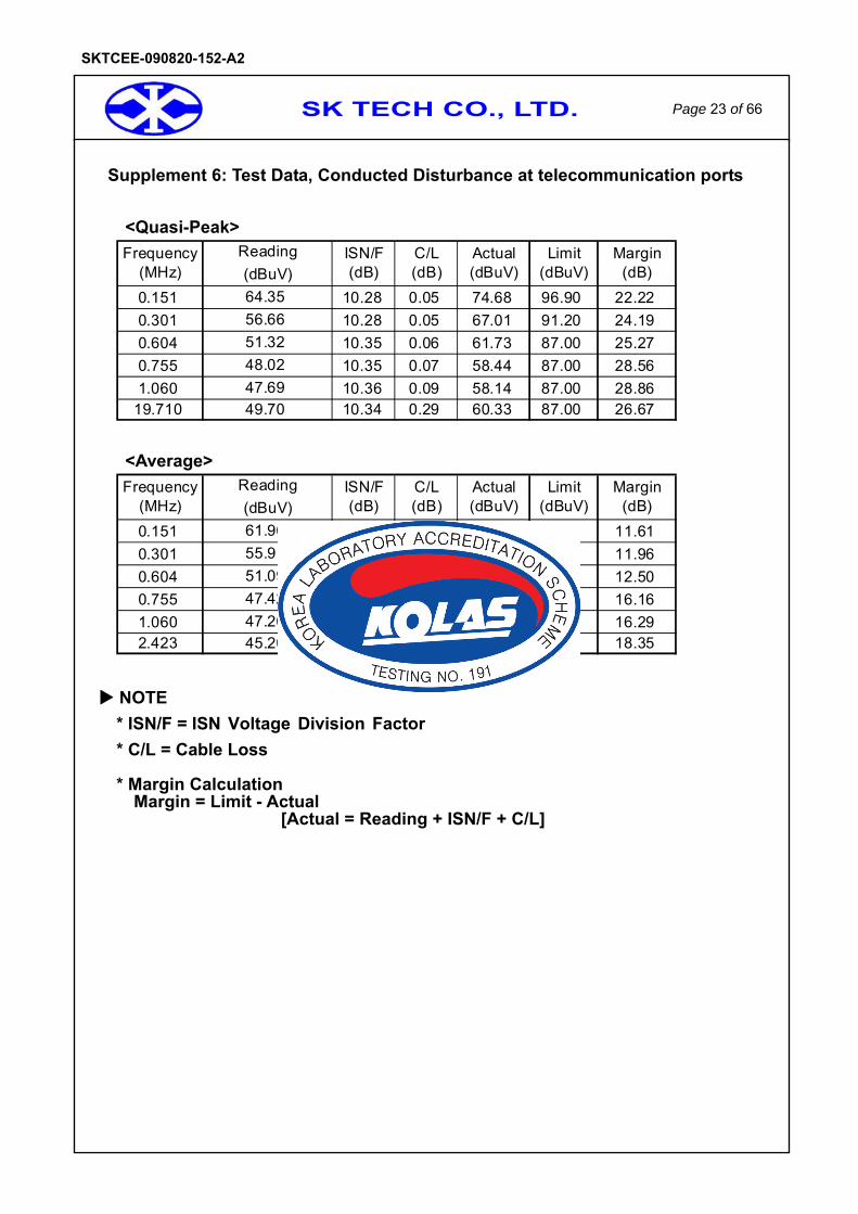
Supplement 6: Test Data, Conducted Disturbance at telecommunication ports
<Quasi-Peak>
0.151 10.28 0.05 74.68 96.90 22.220.301 10.28 0.05 67.01 91.20 24.190.604 10.35 0.06 61.73 87.00 25.270.755 10.35 0.07 58.44 87.00 28.561.060 10.36 0.09 58.14 87.00 28.86
19.710 10.34 0.29 60.33 87.00 26.6747.6949.70
64.3556.6651.3248.02
Frequency(MHz)
Reading ISN/F(dB)(dBuV)
C/L(dB)
Actual(dBuV)
Limit(dBuV)
Margin(dB)
<Average>
0.151 10.28 0.05 72.29 83.90 11.610.301 10.28 0.05 66.24 78.20 11.960.604 10.35 0.06 61.50 74.00 12.500.755 10.35 0.07 57.84 74.00 16.161.060 10.36 0.09 57.71 74.00 16.292.423 10.33 0.12 55.65 74.00 18.35
47.2645.20
61.9655.9151.0947.42
Frequency(MHz)
Reading ISN/F(dB)(dBuV)
C/L(dB)
Actual(dBuV)
Limit(dBuV)
Margin(dB)
NOTE * ISN/F = ISN Voltage Division Factor * C/L = Cable Loss
* Margin Calculation Margin = Limit - Actual
[Actual = Reading + ISN/F + C/L]

SK TECH CO., LTD. Page 24 of 66
SKTCEE-090820-152-A2
Supplement 7: Spectral Diagram, Conducted Disturbance at telecommunication ports
SK TECH CO., LTD. Page 25 of 66
SKTCEE-090820-152-A2
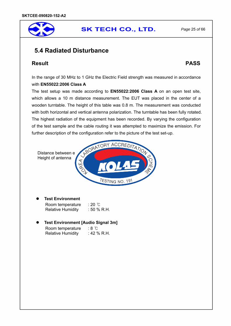
5.4 Radiated Disturbance
Result PASS
In the range of 30 MHz to 1 GHz the Electric Field strength was measured in accordance with EN55022:2006 Class A The test setup was made according to EN55022:2006 Class A on an open test site, which allows a 10 m distance measurement. The EUT was placed in the center of a wooden turntable. The height of this table was 0.8 m. The measurement was conducted with both horizontal and vertical antenna polarization. The turntable has been fully rotated. The highest radiation of the equipment has been recorded. By varying the configuration of the test sample and the cable routing it was attempted to maximize the emission. For further description of the configuration refer to the picture of the test set-up.
Distance between equipment and antenna : 10m Height of antenna : 1 – 4m
Test Environment Room temperature : 20 Relative Humidity : 50 % R.H.
Test Environment [Audio Signal 3m]
Room temperature : 8 Relative Humidity : 42 % R.H.

SK TECH CO., LTD. Page 26 of 66
SKTCEE-090820-152-A2
Table 2: Test Data, Radiated Disturbance
Frequency Reading Pol. Angle Height Correction Factor T-Fact Data Limits Margin
[MHz] [dBuV/m] [m] Antenna Cable [dB] [dBuV/m] [dBuV/m] [dB]
125.02 20.3 V 132 1.3 10.8 1.0 11.8 32.1 40.0 7.9 250.00 25.0 V 253 1.0 11.3 1.5 12.8 37.8 47.0 9.2 300.04 13.5 V 260 1.0 12.9 1.6 14.5 28.0 47.0 19.0 331.76 14.2 H 258 2.4 13.6 1.7 15.3 29.5 47.0 17.5 398.12 15.6 V 192 1.4 14.8 1.8 16.6 32.2 47.0 14.8 450.06 8.9 H 54 2.0 16.4 2.0 18.4 27.3 47.0 19.7 500.01 17.4 V 180 1.7 17.1 2.1 19.2 36.6 47.0 10.4
[Audio Signal 3m]
Frequency Reading Pol. Angle Height Correction Factor T-Fact Data Limits Margin
[MHz] [dBuV/m] [m] Antenna Cable [dB] [dBuV/m] [dBuV/m] [dB]
225.02 9.7 V 342 1.0 11.2 1.6 12.8 22.4 40.0 17.6 250.01 25.7 V 314 1.0 12.6 1.7 14.3 40.0 47.0 7.0 269.57 20.0 V 249 1.1 12.6 1.7 14.3 34.3 47.0 12.7 375.02 12.3 V 342 1.0 13.5 2.0 15.5 27.8 47.0 19.2 398.14 13.2 H 87 2.0 13.8 2.1 15.9 29.1 47.0 17.9 500.01 14.8 H 332 3.3 15.8 2.3 18.1 32.9 47.0 14.1
Table. Radiated Measurements at 10-meters
NOTES: 1. All modes of operation were investigated
and the worst-case emission are reported.
2. All other emission are non-significant.
3. Measurements using CISPR Quasi-Peak mode.
4. H = Horizontal, V = Vertical Polarization
5. Data = Real Reading + T – Factor (Antenna + Cable) 6. Margin = Limits – Data
SK TECH CO., LTD. Page 27 of 66
SKTCEE-090820-152-A2
6. Test Results IMMUNITY
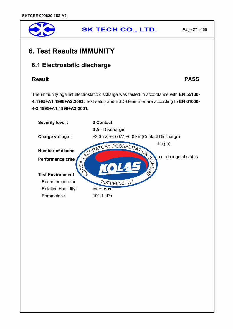
6.1 Electrostatic discharge
Result PASS
The immunity against electrostatic discharge was tested in accordance with EN 55130-4:1995+A1:1998+A2:2003. Test setup and ESD-Generator are according to EN 61000-4-2:1995+A1:1998+A2:2001.
Severity level : 3 Contact 3 Air Discharge Charge voltage : ±2.0 kV, ±4.0 kV, ±6.0 kV (Contact Discharge) ±2.0 kV, ±4.0 kV, ±8.0 kV (Air Discharge) Number of discharges : >10 per test point
Performance criterion : There was no damage, malfunction or change of status during the test.
Test Environment
Room temperature : 23 Relative Humidity : 54 % R.H. Barometric : 101.1 kPa
SK TECH CO., LTD. Page 28 of 66
SKTCEE-090820-152-A2
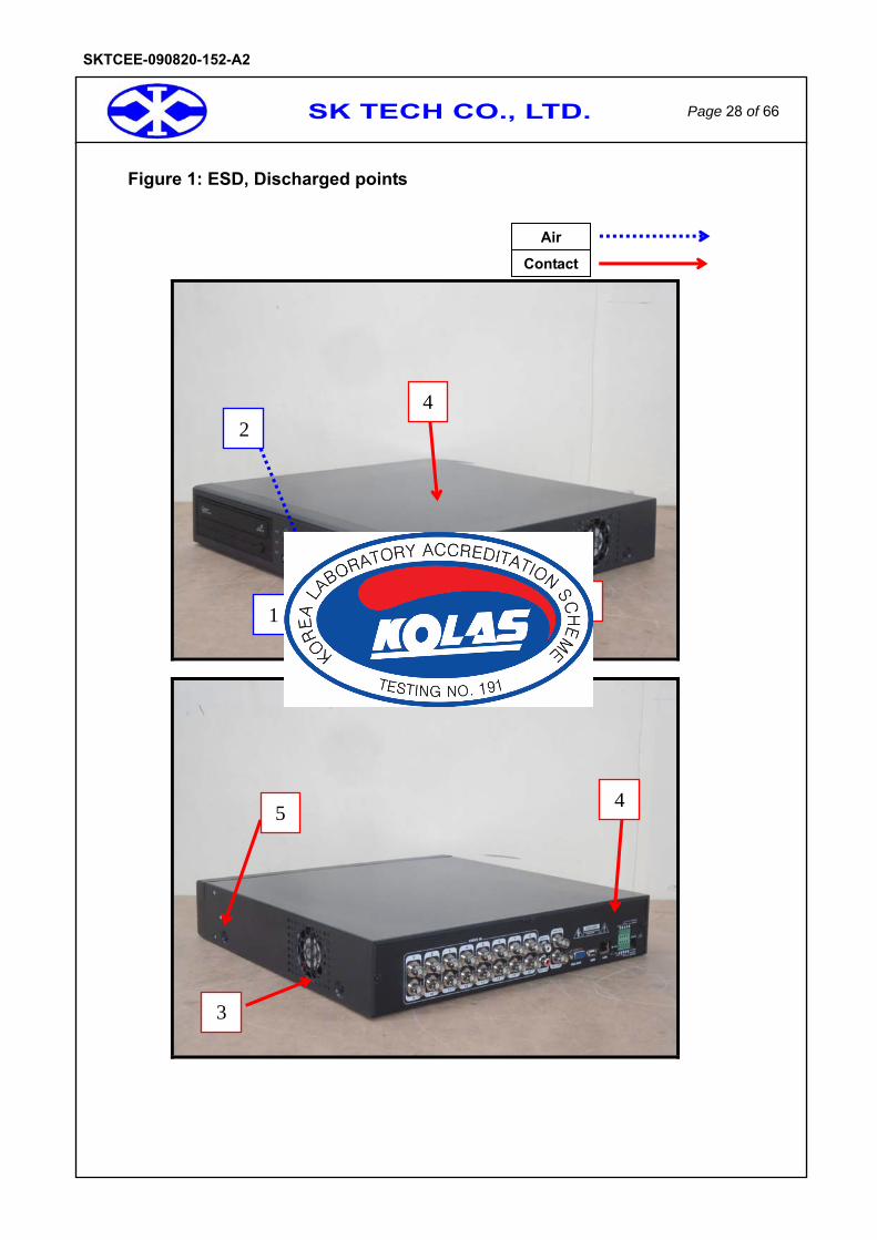
Figure 1: ESD, Discharged points
Air
Contact
1
4
4
3
2
3
5

SK TECH CO., LTD. Page 29 of 66
SKTCEE-090820-152-A2
Table 3: ESD, Positive / Negative Polarity # No.s are reference to the picture of 28 page.
No. Position Kind of Discharge Result Remarks
① Enclosure (Front) Air PASS Equipment operated as intended,No disturbance of function
② Function Keys Air PASS Equipment operated as intended,No disturbance of function
③ Enclosure (Rear, Left, Right, Top) Contact PASS Equipment operated as intended,
No disturbance of function
④ All Screw Contact PASS Equipment operated as intended,No disturbance of function
⑤ HCP, VCP Contact PASS Equipment operated as intended,No disturbance of function

SK TECH CO., LTD. Page 30 of 66
SKTCEE-090820-152-A2
6.2 Radiated radio-frequency electromagnetic field
Result PASS
The immunity against radio-frequency electromagnetic fields in the frequency range between 80 and 2000 MHz was tested in accordance to EN 50130-4:2006. The test setup was made according to EN 61000-4-3:2002+A1:2002 in an anechoic chamber. The EUT has been placed in the center of a wooden turntable. The height of this table was 0.8 m. The field strength was monitored by an isotropic sensor during the complete test. The isotropic sensor was located beside the equipment. The antenna has been orientated for both horizontal and vertical polarization. The distance between antenna and the equipment under testing was at least 3m. The tests have been performed with the antenna facing each of the four sides of the EUT.
Severity level : 1, 2, 3 Field strength : 1V/m,3V/m,10V/m Freq. Range : 80 ~ 1000 MHz, 1000 MHz~2000 MHz Modulation : AM 80 % 1 kHz sine-wave PM, 1 Hz(0.5s ON : 0.5s OFF) Criterion for compliance:
There was no damage, malfunction or change of status during the test.
Step size : 1 % of fundamental
Sweep capability : ≤1.5x10⁻³ decade/s
Dwell time 3 sec
Test Environment Room temperature : 24 Relative Humidity : 58 % R.H. Barometric : 100.8 kPa
SK TECH CO., LTD. Page 31 of 66
SKTCEE-090820-152-A2
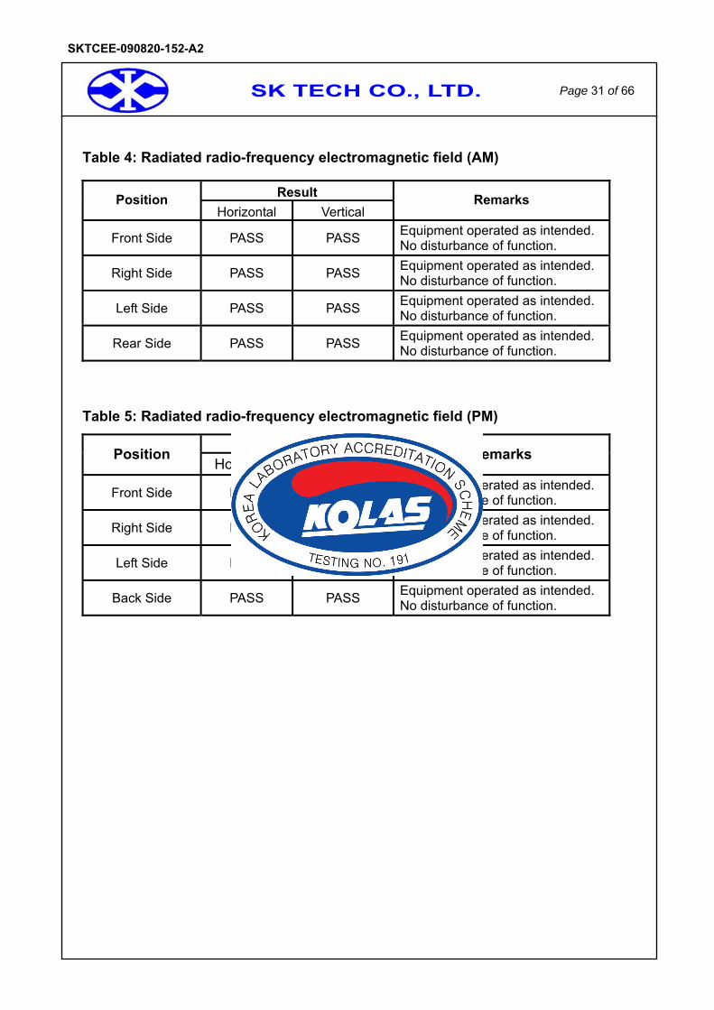
Table 4: Radiated radio-frequency electromagnetic field (AM)
Result Position Horizontal Vertical
Remarks
Front Side PASS PASS Equipment operated as intended. No disturbance of function.
Right Side PASS PASS Equipment operated as intended. No disturbance of function.
Left Side PASS PASS Equipment operated as intended. No disturbance of function.
Rear Side PASS PASS Equipment operated as intended. No disturbance of function.
Table 5: Radiated radio-frequency electromagnetic field (PM)
Result (PM) Position
Horizontal Vertical Remarks
Front Side PASS PASS Equipment operated as intended. No disturbance of function.
Right Side PASS PASS Equipment operated as intended. No disturbance of function.
Left Side PASS PASS Equipment operated as intended. No disturbance of function.
Back Side PASS PASS Equipment operated as intended. No disturbance of function.
SK TECH CO., LTD. Page 32 of 66
SKTCEE-090820-152-A2
6.3 Electrical fast transient/burst
Result PASS
The immunity against fast transients was tested on the power line and all signal lines which length may exceed 3m according to the manufacturers specification in accordance to EN 50130-4:1995+A1:1998+A2:2003. Test setup with capacitive clamp and fast transient noise generator was according to EN 61000-4-4:2004. The un-used signal connector of the clamp has been terminated with a 50 Ωresistor. The distance between the EUT and all other conductive structures, except the ground plane beneath the EUT, was more than 50 cm. The distance between clamp and EUT was about 30 cm.
Severity level : 1, 2, 3 Test voltage :
a.c. mains supply lines (kV) 0.5, 1, 2 other supply/signal lines (kV) 0.25, 0.5, 1
Polarity : Negative / positive Repetition frequency : 5 kHz Criterion for compliance: There was no damage, malfunction or change of
status during the test. Duration per application (sec) ≥60sec
Test Environment Room temperature : 23 Relative Humidity : 54 % R.H. Barometric : 101.1 kPa
Test Environment [Audio Signal 3m]
Room temperature : 21 Relative Humidity : 50 % R.H. Barometric : 101.6 kPa

SK TECH CO., LTD. Page 33 of 66
SKTCEE-090820-152-A2
Table 6: Electrical fast transient, AC Power Lines, Positive/Negative Polarity
Line Result Remarks
L1 0.5 kV1 kV 2 kV
PASS PASS PASS
Equipment operated as intended. No disturbance of function.
L2 0.5 kV1 kV 2 kV
PASS PASS PASS
Equipment operated as intended. No disturbance of function.
L1 + L2 0.5 kV1 kV 2 kV
PASS PASS PASS
Equipment operated as intended. No disturbance of function.
PE 0.5 kV1 kV 2 kV
PASS PASS PASS
Equipment operated as intended. No disturbance of function.
L1 + PE 0.5 kV1 kV 2 kV
PASS PASS PASS
Equipment operated as intended. No disturbance of function.
L2 + PE 0.5 kV1 kV 2 kV
PASS PASS PASS
Equipment operated as intended. No disturbance of function.
L1 + L2 + PE 0.5 kV1 kV 2 kV
PASS PASS PASS
Equipment operated as intended. No disturbance of function.
Table 7: Burst, other supply / signal lines, Positive / Negative Polarity
Line Result Remarks
Video In 250 V 500 V 1 kV
PASS PASS PASS
Equipment operated as intended. No disturbance of function.
Video Out 250 V 500 V 1 kV
PASS PASS PASS
Equipment operated as intended. No disturbance of function.
Alarm Out/ Sensor In
250 V 500 V 1 kV
PASS PASS PASS
Equipment operated as intended. No disturbance of function.
LAN 250 V 500 V 1 kV
PASS PASS PASS
Equipment operated as intended. No disturbance of function.
Audio In/Out 250 V 500 V 1 kV
PASS PASS PASS
Equipment operated as intended. No disturbance of function.
SK TECH CO., LTD. Page 34 of 66
SKTCEE-090820-152-A2
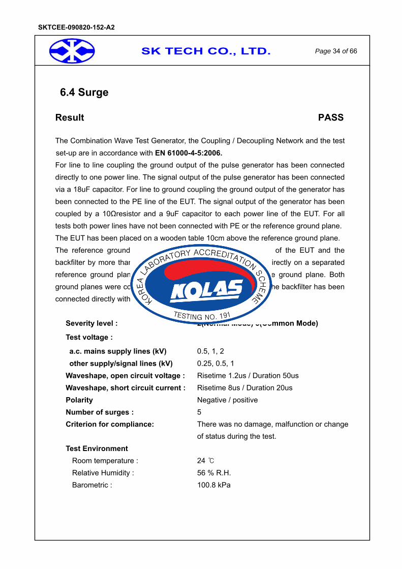
6.4 Surge
Result PASS
The Combination Wave Test Generator, the Coupling / Decoupling Network and the test set-up are in accordance with EN 61000-4-5:2006. For line to line coupling the ground output of the pulse generator has been connected directly to one power line. The signal output of the pulse generator has been connected via a 18uF capacitor. For line to ground coupling the ground output of the generator has been connected to the PE line of the EUT. The signal output of the generator has been coupled by a 10Ωresistor and a 9uF capacitor to each power line of the EUT. For all tests both power lines have not been connected with PE or the reference ground plane. The EUT has been placed on a wooden table 10cm above the reference ground plane. The reference ground plane exceeded the projected geometry of the EUT and the backfilter by more than 20 cm. The backfilter has been placed directly on a separated reference ground plane about 10 cm above the main reference ground plane. Both ground planes were connected together. The ground terminal of the backfilter has been connected directly with its reference ground plane.
Severity level : 2(Normal Mode) 3(Common Mode)
Test voltage :
a.c. mains supply lines (kV) 0.5, 1, 2 other supply/signal lines (kV) 0.25, 0.5, 1
Waveshape, open circuit voltage : Risetime 1.2us / Duration 50us Waveshape, short circuit current : Risetime 8us / Duration 20us Polarity Negative / positive
Number of surges : 5 Criterion for compliance: There was no damage, malfunction or change of status during the test. Test Environment
Room temperature : 24 Relative Humidity : 56 % R.H. Barometric : 100.8 kPa
SK TECH CO., LTD. Page 35 of 66
SKTCEE-090820-152-A2
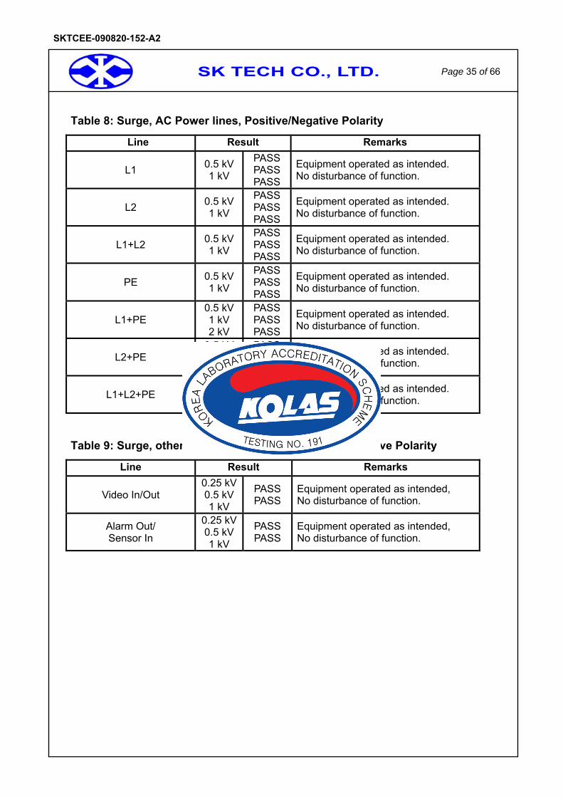
Table 8: Surge, AC Power lines, Positive/Negative Polarity
Line Result Remarks
L1 0.5 kV1 kV
PASS PASS PASS
Equipment operated as intended. No disturbance of function.
L2 0.5 kV1 kV
PASS PASS PASS
Equipment operated as intended. No disturbance of function.
L1+L2 0.5 kV1 kV
PASS PASS PASS
Equipment operated as intended. No disturbance of function.
PE 0.5 kV1 kV
PASS PASS PASS
Equipment operated as intended. No disturbance of function.
L1+PE 0.5 kV1 kV 2 kV
PASS PASS PASS
Equipment operated as intended. No disturbance of function.
L2+PE 0.5 kV1 kV 2 kV
PASS PASS PASS
Equipment operated as intended. No disturbance of function.
L1+L2+PE 0.5 kV1 kV 2 kV
PASS PASS PASS
Equipment operated as intended. No disturbance of function.
Table 9: Surge, other supply /signal lines, Positive/Negative Polarity
Line Result Remarks
Video In/Out 0.25 kV0.5 kV1 kV
PASS PASS
Equipment operated as intended, No disturbance of function.
Alarm Out/ Sensor In
0.25 kV0.5 kV1 kV
PASS PASS
Equipment operated as intended, No disturbance of function.
SK TECH CO., LTD. Page 36 of 66
SKTCEE-090820-152-A2
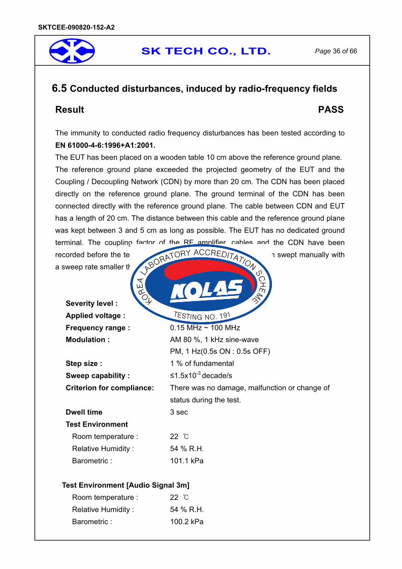
6.5 Conducted disturbances, induced by radio-frequency fields
Result PASS
The immunity to conducted radio frequency disturbances has been tested according to EN 61000-4-6:1996+A1:2001. The EUT has been placed on a wooden table 10 cm above the reference ground plane. The reference ground plane exceeded the projected geometry of the EUT and the Coupling / Decoupling Network (CDN) by more than 20 cm. The CDN has been placed directly on the reference ground plane. The ground terminal of the CDN has been connected directly with the reference ground plane. The cable between CDN and EUT has a length of 20 cm. The distance between this cable and the reference ground plane was kept between 3 and 5 cm as long as possible. The EUT has no dedicated ground terminal. The coupling factor of the RF amplifier, cables and the CDN have been recorded before the test. The specified frequency range has been swept manually with a sweep rate smaller than 1.5 x 10⁻³ decade / sec.
Severity level : 1, 2, 3 Applied voltage : 1V, 3V, 10V Frequency range : 0.15 MHz ~ 100 MHz Modulation : AM 80 %, 1 kHz sine-wave PM, 1 Hz(0.5s ON : 0.5s OFF) Step size : 1 % of fundamental Sweep capability : ≤1.5x10⁻³ decade/s Criterion for compliance: There was no damage, malfunction or change of status during the test. Dwell time 3 sec
Test Environment Room temperature : 22 Relative Humidity : 54 % R.H. Barometric : 101.1 kPa
Test Environment [Audio Signal 3m]
Room temperature : 22 Relative Humidity : 54 % R.H. Barometric : 100.2 kPa
SK TECH CO., LTD. Page 37 of 66
SKTCEE-090820-152-A2
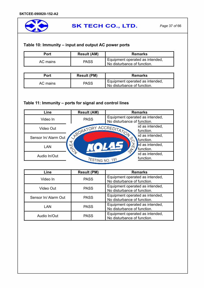
Table 10: Immunity – input and output AC power ports
Port Result (AM) Remarks
AC mains PASS Equipment operated as intended, No disturbance of function.
Port Result (PM) Remarks
AC mains PASS Equipment operated as intended, No disturbance of function.
Table 11: Immunity – ports for signal and control lines
Line Result (AM) Remarks
Video In PASS Equipment operated as intended, No disturbance of function.
Video Out PASS Equipment operated as intended, No disturbance of function.
Sensor In/ Alarm Out PASS Equipment operated as intended, No disturbance of function.
LAN PASS Equipment operated as intended, No disturbance of function.
Audio In/Out PASS Equipment operated as intended, No disturbance of function.
Line Result (PM) Remarks
Video In PASS Equipment operated as intended, No disturbance of function.
Video Out PASS Equipment operated as intended, No disturbance of function.
Sensor In/ Alarm Out PASS Equipment operated as intended, No disturbance of function.
LAN PASS Equipment operated as intended, No disturbance of function.
Audio In/Out PASS Equipment operated as intended, No disturbance of function.

SK TECH CO., LTD. Page 38 of 66
SKTCEE-090820-152-A2
6.6 Voltage dips, Voltage interruptions
Result PASS
Voltage dips, short interruptions and Voltage Variation Immunity tests and it’s test setup were carried out in accordance with EN61000-4-11:2004
<EN 50130-4:1995+A1:1998+A2:2003>
Test Level % Ut
Voltage dip and short
interruptions % Ut
Duration of Reduction Criteria Result Remark
70 30 0.5, 1, 5, 10 PASS PASS Equipment operated as intended, No disturbance of function.
40 60 0.5, 1, 5, 10 PASS PASS Equipment operated as intended, No disturbance of function.
0 100 0.5, 1, 5 PASS PASS Equipment operated as intended, No disturbance of function.
· Test Environment Room temperature : 23 Relative Humidity : 50 % R.H. Barometric : 101.1 kPa
SK TECH CO., LTD. Page 39 of 66
SKTCEE-090820-152-A2
6.7 Mains supply voltage variations
Result PASS
No reference of mains supply voltage variation immunity test can be made to an internationally accepted standard a resent.
Mains supply voltage conditions Result
Supply voltage max (Umax) Unom + 10% Equipment operated as intended, No disturbance of function
Supply voltage min (Umin) Unom - 15% Equipment operated as intended, No disturbance of function
· Test Environment Room temperature : 23 Relative Humidity : 50 % R.H. Barometric : 101.1 kPa Supplied voltages : 230V
SK TECH CO., LTD. Page 40 of 66
SKTCEE-090820-152-A2
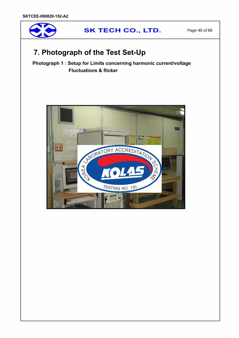
7. Photograph of the Test Set-Up Photograph 1 : Setup for Limits concerning harmonic current/voltage
Fluctuations & flicker
SK TECH CO., LTD. Page 41 of 66
SKTCEE-090820-152-A2
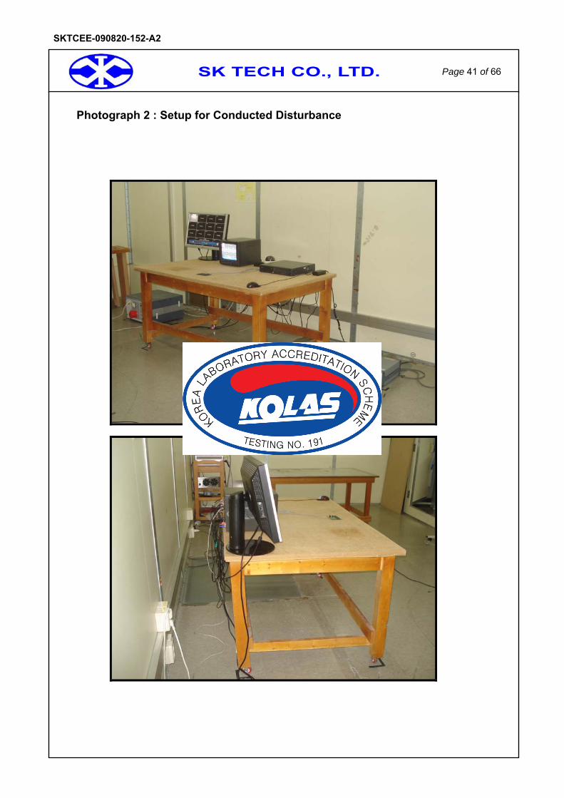
Photograph 2 : Setup for Conducted Disturbance
SK TECH CO., LTD. Page 42 of 66
SKTCEE-090820-152-A2
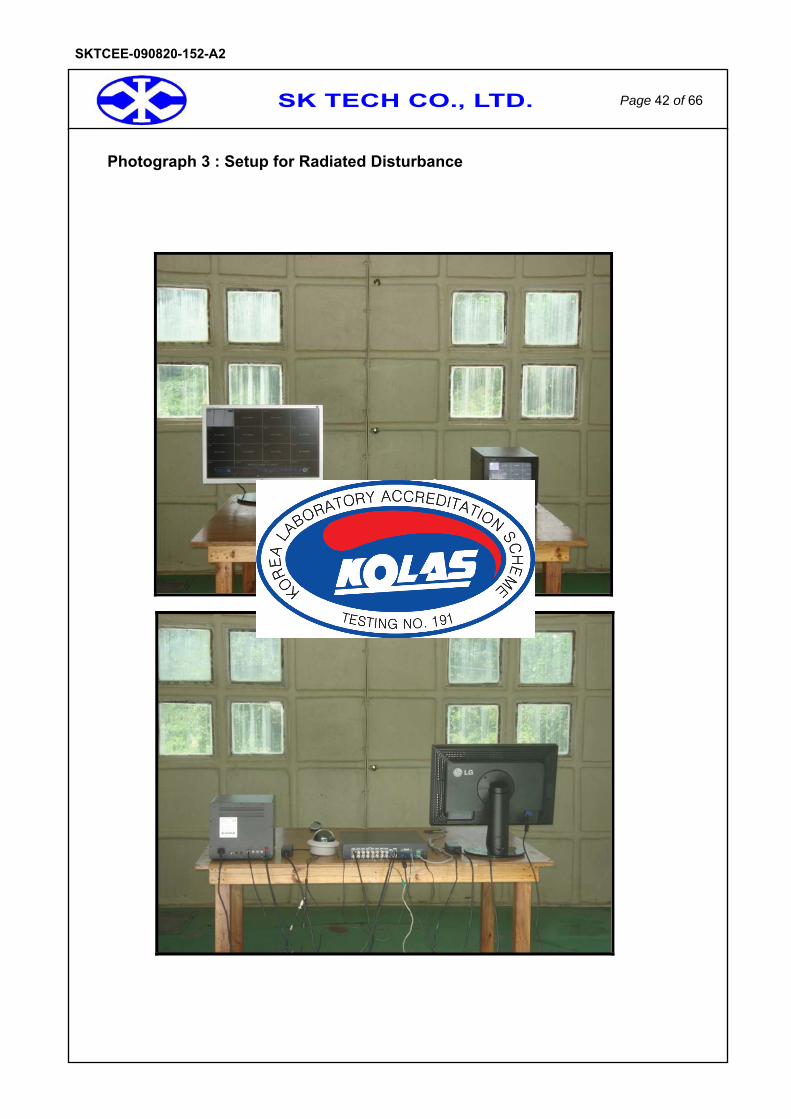
Photograph 3 : Setup for Radiated Disturbance
SK TECH CO., LTD. Page 43 of 66
SKTCEE-090820-152-A2
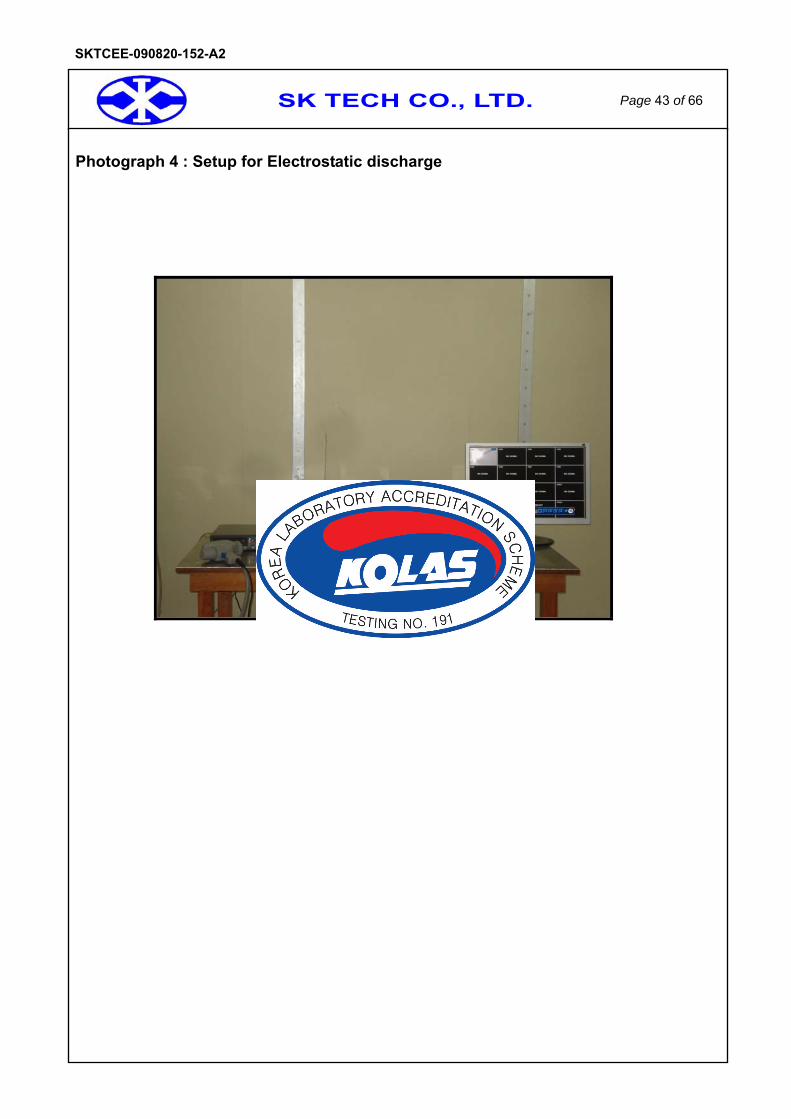
Photograph 4 : Setup for Electrostatic discharge

SK TECH CO., LTD. Page 44 of 66
SKTCEE-090820-152-A2
Photograph 5: Setup for Radiated radio-frequency electromagnetic field
SK TECH CO., LTD. Page 45 of 66
SKTCEE-090820-152-A2
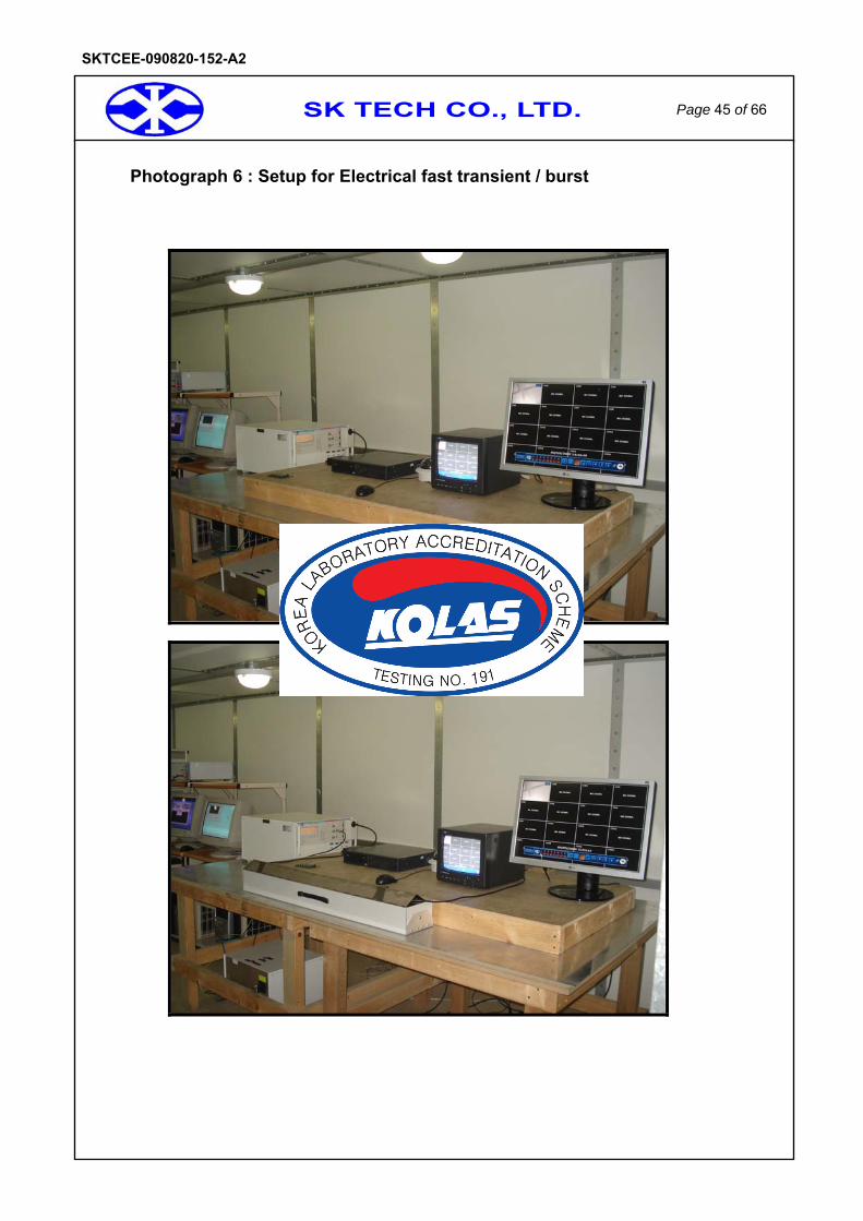
Photograph 6 : Setup for Electrical fast transient / burst
SK TECH CO., LTD. Page 46 of 66
SKTCEE-090820-152-A2
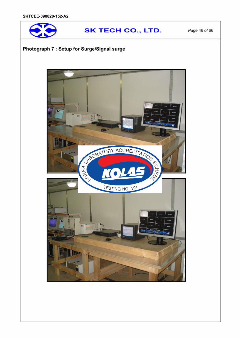
Photograph 7 : Setup for Surge/Signal surge
SK TECH CO., LTD. Page 47 of 66
SKTCEE-090820-152-A2
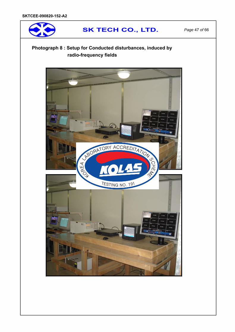
Photograph 8 : Setup for Conducted disturbances, induced by radio-frequency fields

SK TECH CO., LTD. Page 48 of 66
SKTCEE-090820-152-A2
Photograph 9 : Setup for Voltage dips, Voltage interruptions

SK TECH CO., LTD. Page 49 of 66
SKTCEE-090820-152-A2
Photograph 10 : Setup for Mains supply voltage variations

SK TECH CO., LTD. Page 50 of 66
SKTCEE-090820-152-A2
Photographs of EUT < Front >

SK TECH CO., LTD. Page 51 of 66
SKTCEE-090820-152-A2
Photographs of EUT < Rear >
SK TECH CO., LTD. Page 52 of 66
SKTCEE-090820-152-A2
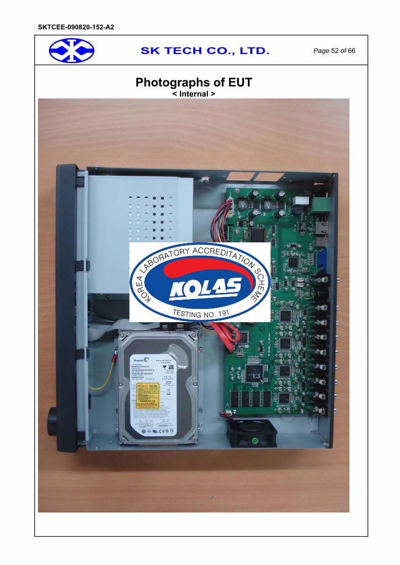
Photographs of EUT < Internal >
SK TECH CO., LTD. Page 53 of 66
SKTCEE-090820-152-A2
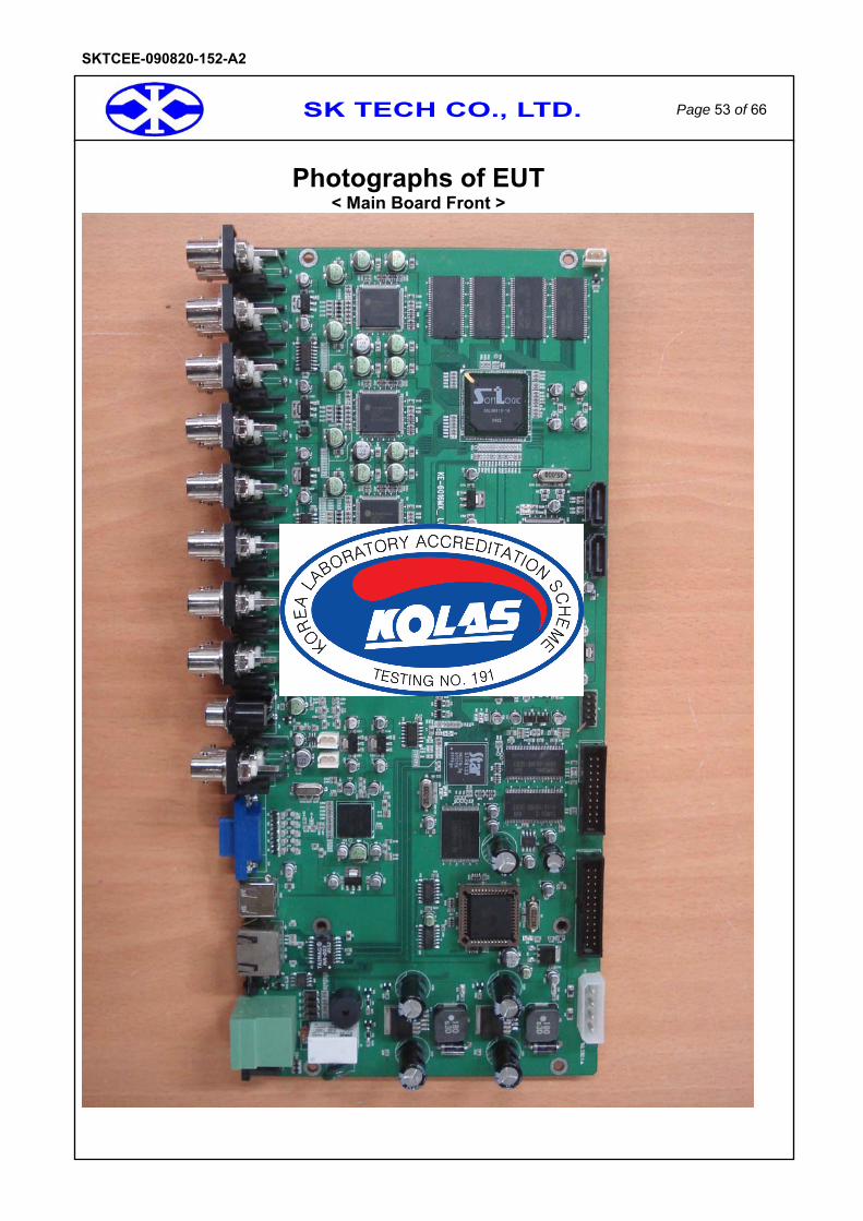
Photographs of EUT < Main Board Front >

SK TECH CO., LTD. Page 54 of 66
SKTCEE-090820-152-A2
Photographs of EUT < Main Board Rear >
SK TECH CO., LTD. Page 55 of 66
SKTCEE-090820-152-A2
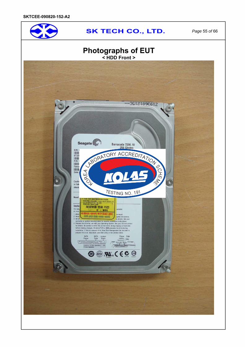
Photographs of EUT < HDD Front >

SK TECH CO., LTD. Page 56 of 66
SKTCEE-090820-152-A2
Photographs of EUT < HDD Rear >

SK TECH CO., LTD. Page 57 of 66
SKTCEE-090820-152-A2
Photographs of EUT < DVD Writer Front >
SK TECH CO., LTD. Page 58 of 66
SKTCEE-090820-152-A2
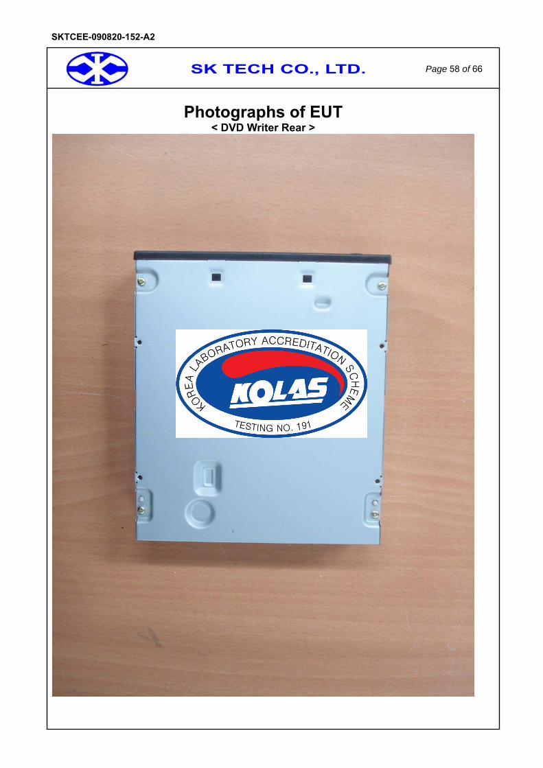
Photographs of EUT < DVD Writer Rear >

SK TECH CO., LTD. Page 59 of 66
SKTCEE-090820-152-A2
Photographs of EUT < Front Internal >

SK TECH CO., LTD. Page 60 of 66
SKTCEE-090820-152-A2
Photographs of EUT < Front Board Front >

SK TECH CO., LTD. Page 61 of 66
SKTCEE-090820-152-A2
Photographs of EUT < Front Board Rear >
SK TECH CO., LTD. Page 62 of 66
SKTCEE-090820-152-A2
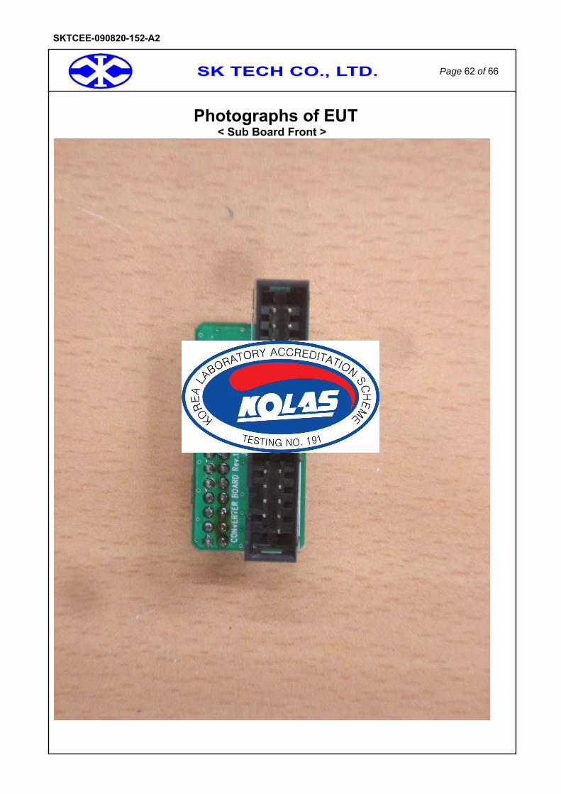
Photographs of EUT < Sub Board Front >

SK TECH CO., LTD. Page 63 of 66
SKTCEE-090820-152-A2
Photographs of EUT < Sub Board Rear >

SK TECH CO., LTD. Page 64 of 66
SKTCEE-090820-152-A2
Photographs of EUT < AC Adapter Front >
SK TECH CO., LTD. Page 65 of 66
SKTCEE-090820-152-A2
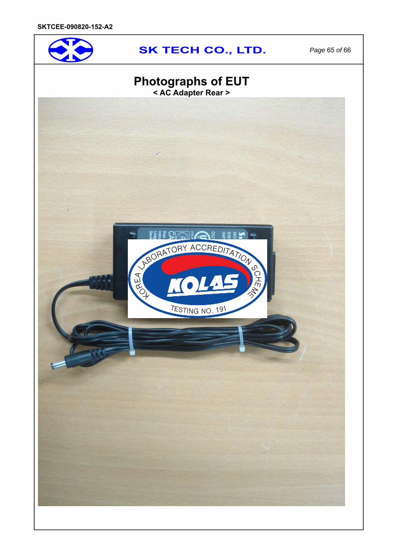
Photographs of EUT < AC Adapter Rear >
SK TECH CO., LTD. Page 66 of 66
SKTCEE-090820-152-A2
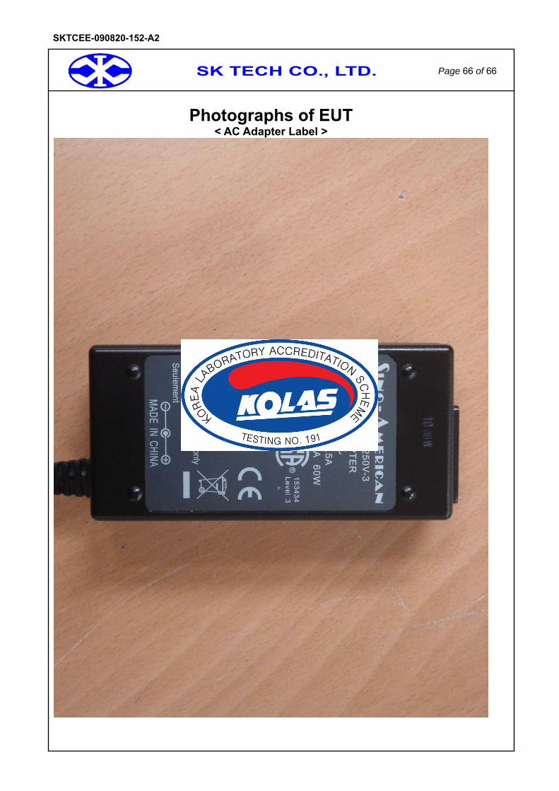
Photographs of EUT < AC Adapter Label >