site survey considerations - axis communications · pdf filebefore installing a surveillance...
TRANSCRIPT

Site survey considerations
ARTICLE

Table of contents
1. Establishing the purpose 4
2. Site survey framework 5
3. Camera selection and placement 6
4. Network infrastructure 8
5. Power over Ethernet (PoE) 9

3
IntroductionBefore installing a surveillance system, we recommend you do a site survey and document it for future needs and upgrades.
There are many building blocks of a site survey, and in this guide we help identifying some of them. One of the first things to define is the purpose of the installation. The physical location and the customer’s needs are two other important things to consider, as well as reviewing the existing security procedures and establish the new ones. What areas to monitor and why, which cameras to select and where to place them, and the current network infrastructure are also key factors for a successful surveillance installa-tion.
In this guide, we present site survey considerations in five steps.

4
1. Establishing the purpose The first step in designing a surveillance system must always be to define the purpose of the installation. The most important steps in this process include interviewing the client and reviewing the site, in order to find out more about the business and its operations.
Purpose of surveillance system at XYZ Corporation – example one
1. Provide security staff with visual support covering the back boundaries and fence line of the prop-erty in general, as well as specific vehicle entrances, to enhance the Security Department’s ability to document authorized access and respond to trespassers as required.
2. Visual identification and documentation of all individuals entering and leaving the property through the south gate, in order to obtain an accurate count and identification of all individuals on the site in the event of an emergency.
3. Event-driven recordings outside of business hours to reduce bandwidth consumption in the net-work and decrease storage space required.
Purposes of cameras at XYZ Corporation – example two
1. The purpose for cameras 1, 3, 4 and 5 is to provide general documentation of activity in the area, without specific identification of individuals
2. The purpose of camera 2 is twofold:a. Provide facial identification of all individuals entering through door number 4 between 5:00
PM (17.00) and 07:00 AM (07.00).b. Provide general viewing of activity in the lobby at door number 4 between 7:00 AM (07.00)
and 5:00 PM (17.00).
Figure 1. A site survey will help planning the surveillance system.

5
2. Site survey frameworkWhen planning for your surveillance system, the physical location and the customer’s needs are two of the building blocks of a site survey. Reviewing the existing security procedures and rules with the cus-tomer can help you identify improvements that can be made. Performing a threat analysis to identify the need for surveillance is a requirement, but it will also help you identify what the customer is trying to prevent or protect against.
Other building blocks of the site survey include defining the overall requirements, areas to monitor and why, the necessary levels of security. Another important aspect is the current infrastructure, such as existing equipment, available lighting, cabling, and camera mounting conditions.
The site survey helps you identify areas of interest, some of them overlooked by the customer. Typical areas to monitor include the following:
> Entrances > Emergency exits > Driving and walking gates > Cashier areas > ATM machines > Waiting areas / lines > Reception areas > Loading docks / delivery entrances > Hallways > Perimeter areas / fences / windows

6
3. Camera selection and placementWhen selecting and placing cameras, it’s important to know the client’s surveillance needs. Do you need detection of objects, recognition of people, or identification of unique facial characteristics?
The operational requirements determine if you merely need to see if any people are in the area, if you need to be able to recognize individuals, or if you need to identify persons. When we speak of recognition versus identification, it’s implied that recognition refers to someone known to you, and that identification provides enough detail for you to identify the person, regardless of surroundings and dress.
Area coverage and capture points
One camera will provide an overall view of the scene, but will probably not provide enough details for identifying individuals in the area. If identification is one of the surveillance goals, then an additional camera needs to be included in the design; see figure 3 below. Identification is now possible when a person enters a large, monitored area. Information about the number of people in the room and their locations can still be objectively retrieved through an additional wide-angle camera.
The capture point was already established, since all people enter the room by the one door available.
Figure 3. One camera providing an overall view, and an additional camera for identifying details.
Identification Recognition Detection
Figure 2. The different resolutions for Identification, Recognition and Detection.

7
Fixed versus Pan/Tilt/Zoom (PTZ) cameras
Figure XX illustrates how four fixed cameras cover a majority of the parking area, whereas through pan-ning, one PTZ can cover the same area. However, a PTZ camera can view only one small segment of the area at a time, while the fixed cameras guarantee coverage at all times.
Figure 4. Coverage areas for fixed versus PTZ camera.

8
4. Network infrastructureVerifying network equipment hardware
Verify the existing equipment and functionality, ensure that the network does what it needs to do, and make sure the system will support future needs. Verify whether the system will support advanced fea-tures that might be required, such as Quality of Service (QoS), Power over Ethernet (PoE), and Virtual Local Area Networks (VLANs).
Certifying the cabling
Certify the existing cabling. Make sure the cabling is “future-proofed” and has sufficient capacity to handle the desired network load. Verify the performance by using network certification tools.
Creating the correct network topology
When creating a network topology, never use a daisy chain infrastructure, because this is a vulnerable system with potential bottleneck issues and low redundancy.
Always use a star or redundant star topology, since these provide a minimized network load on each switch, reduced load on the server, and a high level of redundancy.
Floors 5-8
Basement
Floors 9-12
Floors 14-17
Floors 1-4
Floors 5-8
Basement
Floors 9-12
Floors 14-17
Floors 1-4
Figure 5. Daisy chain topology. Figure 6. Star topology.
9
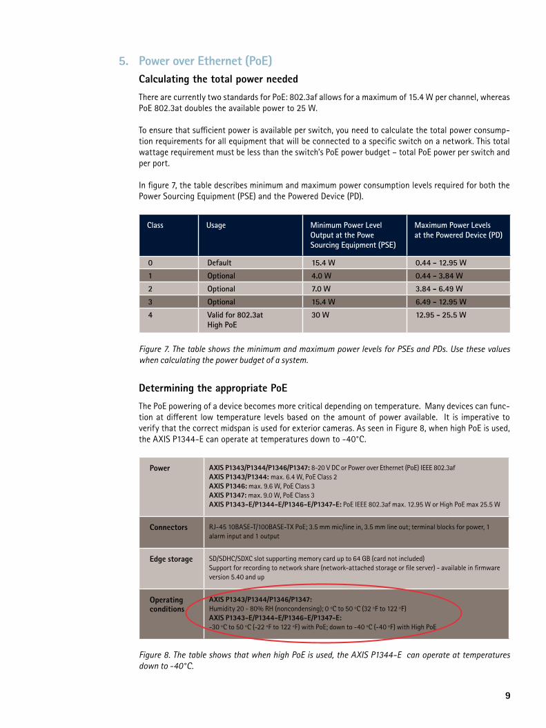
5. Power over Ethernet (PoE)Calculating the total power needed
There are currently two standards for PoE: 802.3af allows for a maximum of 15.4 W per channel, whereas PoE 802.3at doubles the available power to 25 W.
To ensure that sufficient power is available per switch, you need to calculate the total power consump-tion requirements for all equipment that will be connected to a specific switch on a network. This total wattage requirement must be less than the switch’s PoE power budget – total PoE power per switch and per port.
In figure 7, the table describes minimum and maximum power consumption levels required for both the Power Sourcing Equipment (PSE) and the Powered Device (PD).
Class Usage Minimum Power LevelOutput at the Powe Sourcing Equipment (PSE)
Maximum Power Levelsat the Powered Device (PD)
0 Default 15.4 W 0.44 - 12.95 W
1 Optional 4.0 W 0.44 - 3.84 W
2 Optional 7.0 W 3.84 - 6.49 W
3 Optional 15.4 W 6.49 - 12.95 W
4 Valid for 802.3atHigh PoE
30 W 12.95 - 25.5 W
Figure 7. The table shows the minimum and maximum power levels for PSEs and PDs. Use these values when calculating the power budget of a system.
Determining the appropriate PoE
The PoE powering of a device becomes more critical depending on temperature. Many devices can func-tion at different low temperature levels based on the amount of power available. It is imperative to verify that the correct midspan is used for exterior cameras. As seen in Figure 8, when high PoE is used, the AXIS P1344-E can operate at temperatures down to -40°C.
Power AXIS P1343/P1344/P1346/P1347: 8-20 V DC or Power over Ethernet (PoE) IEEE 802.3afAXIS P1343/P1344: max. 6.4 W, PoE Class 2AXIS P1346: max. 9.6 W, PoE Class 3AXIS P1347: max. 9.0 W, PoE Class 3AXIS P1343-E/P1344-E/P1346-E/P1347-E: PoE IEEE 802.3af max. 12.95 W or High PoE max 25.5 W
Connectors RJ-45 10BASE-T/100BASE-TX PoE; 3.5 mm mic/line in, 3.5 mm line out; terminal blocks for power, 1 alarm input and 1 output
Edge storage SD/SDHC/SDXC slot supporting memory card up to 64 GB (card not included)Support for recording to network share (network-attached storage or file server) - available in firmware version 5.40 and up
Operatingconditions
AXIS P1343/P1344/P1346/P1347: Humidity 20 - 80% RH (noncondensing); 0 ºC to 50 ºC (32 ºF to 122 ºF)AXIS P1343-E/P1344-E/P1346-E/P1347-E: -30 ºC to 50 ºC (-22 ºF to 122 ºF) with PoE; down to -40 ºC (-40 ºF) with High PoE
Figure 8. The table shows that when high PoE is used, the AXIS P1344-E can operate at temperatures down to -40°C.

www.axis.com
496
89/E
N/R
1/12
11
About Axis CommunicationsAs the market leader in network video, Axis is leading the way to a smarter, safer, more secure world — driving the shift from analog to digital video surveillance. Offering network video solutions for professional installations, Axis’ products and solutions are based on an innovative, open technology platform.Axis has more than 1,000 dedicated employees in 40 locations around the world and cooperates with partners covering 179 countries. Founded in 1984, Axis is a Sweden-based IT company listed on NASDAQ OMX Stockholm under the ticker AXIS. For more information about Axis, please visit our website www.axis.com.
©2012 Axis Communications AB. AXIS COMMUNICATIONS, AXIS, ETRAX, ARTPEC and VAPIX are registered trademarks or trademark applications of Axis AB in various jurisdictions. All other company names and products are trademarks or registered trademarks of their respective companies. We reserve the right to introduce modifications without notice.