sip in an interconnector and service provider rolemaguire/degree-project-reports/011220...sip in an...
TRANSCRIPT
SIP in an Interconnector and Service Provider Role
Master of Science Thesis by:
Saman Ahmedi ([email protected]) Martin Altinkaya ([email protected])
Stockholm, December 2001
Version 2
Supervisor: Examiner and supervisor: Stefan Hagbard Prof. Gerald Q. �Chip� Maguire Jr. Telia Mobile AB, Nacka Strand, Stockholm KTH/IMIT, Kista, Stockholm [email protected] [email protected]
K T H T E L I A M O B I L E
SIP in an Interconnector and Service Provider Role
Telia Mobile AB Martin Altinkaya December 2001 Saman Ahmedi
2
ABSTRACT This Master's Thesis concerns the technical problems and solutions in the Telia Mobile�s Golden Gate Architecture. The Golden Gate project will bridge service control from the IP-network to the circuit switched network. Connecting the different users of PSTN, GSM, W-LAN, and GPRS networks together will require solutions to many problems. Most of the problems have already been defined by Telia. Our task is to evaluate two parts of the Golden Gate architecture, namely the Interconnect- and Service Provider roles. The Interconnector provider connects networks of different technical standards and enables other network operators to reach Service Providers on the Internet or other IP-based networks. The role concerns mainly mapping between SS7 signaling and the Session Initiation Protocol (SIP), charging and billing. Via the Interconnector the Service Provider can connect different services to any network. We will describe the SIP-protocol in detail and then we will look into the mapping between SS7 and SIP. We will also propose a charging model. It is important to have a solution that supports roaming between the different networks, we will evaluate such a solution. Most of the protocols (INAP, ENUM, MAP and ISUP) that are involved in the Golden Gate architecture are not completely defined. There are many Internet Drafts that discuss the possible functionality of the protocols and the interworking between them. Many different Internet-workgroups are working with these issues. No one seems to have the right answers for the interconnection between the protocols involved. Since the IP-telephony will probably replace today's telephony systems, it is important to ensure a suitable Quality of Service (QoS), security that guarantees privacy, and a fair billing function. These are the three major problems in the IP-telephony world. IP-Telephony or Voice over IP (VoIP) has been on the market for a long time, there are many �free IP-call sites� that use VoIP, but the quality of the calls are not yet good enough to replace traditional telephony. Our task here is to make sure that the necessary quality of service is provided, and a reliable charging model is used.

SIP in an Interconnector and Service Provider Role
Telia Mobile AB Martin Altinkaya December 2001 Saman Ahmedi
3
Table of Contents ABSTRACT 2
1. Introduction 7 1.1 Signaling Protocols 7 1.1.1 SIP 7 1.2 Numbering Scheme 8 1.2.1 ENUM 8 1.3 INAP 8 1.4 Quality of Service 9 1.5 Charging Models 9 1.6 Problem Statements 10 1.6.1 Main problems with Golden Gate Architecture Implementation 10 1.6.2 What Telia can do to solve those problems 10 1.6.3 Our part in the Golden Gate 10 1.6.4 Methods 11 1.6.5 Structure of this document 11 2. Multi-networks services 12 2.1 Introduction to Telia's Golden Gate Architecture 12 2.2 Protocol definitions 13
2.2.1 INAP 13 2.2.2 MAP 13
2.2.3 ISUP 13 2.3 Business Architecture 13 2.4 Technical Architecture 13 2.4.1 Session Control Gateway 14 2.5 Information Architecture 15
3. Introduction to IP-Telephony 16 3.1 IP-Telephony 16 3.2 Gateways 17 3.3 Challenges of IP-Telephony 18
4. Session Initiation Protocol (SIP) 19 4.1 An introduction to SIP 19 4.2 SIP Componets 20 4.2.1 SIP-session 21 4.3 Addressing and Naming 22 4.4 Description of the requests 22
4.4.1 INVITE 22 4.4.2 ACK 23 4.4.3 OPTION 24 4.4.4 BYE 24 4.4.5 CANCEL 24
4.4.6 REGISTER 24 4.5 Session Description Protocol 24 4.6 Real-time Transport Protocol 25
SIP in an Interconnector and Service Provider Role
Telia Mobile AB Martin Altinkaya December 2001 Saman Ahmedi
4
5. ENUM 27 5.1 Introduction 27 5.2 History 27 5.3 Background 28
5.4 How to Use ENUM 28 5.5 NAPTR Resource Records 29 5.6 ENUM and SIP 30 5.7 TRIP 31 5.8 ENUM and Billing 32
5.9 ENUM's role in the future of VoIP 33
6. Intelligent Network 34 6.1 Introduction 34 6.1.1 SS7 Overview 34 6.1.2 Intelligent Network Overview 34 6.1.2.1 IN Based Services 35 6.2 Protocol Architecture for SIP/IN 35
6.3 Underlying Protocols in SS7 37 6.3.1 TCAP 37 6.3.2 ISUP 37 6.3.3 SINAP 37 6.3.4 MAP 37 6.4 Architecture Model for SIP/IN Interworking 38 6.4.1 Architecture entities 38 6.4.2 Enhancement required for SIP/IN Interworking 39 6.4.2.1 Call Control Function 39 6.4.2.2 Service Switching Function 40 6.5 SIP/IN Interaction 40 6.5.1 Originating Call with Core INAP interaction 40 6.5.2 Termination Call with Core INAP interaction 41 6.6 Conclusion 42
7. Quality of Service 43 7.1 Introduction 43 7.2 QoS Attributes 43 7.3 Transport performance related QoS 44 7.3.1 QoS Mediation 44 7.3.2 User selected QoS 45 7.4 3rd Generation Application Categories 45 7.5 QoS Models for Service Provisioning 46 7.5.1 RSVP/IntServ 47 7.5.2 Diffserv 47 7.5.3 Over-provisioning and Best-effort 47 7.5.4 Price-controlled Best-effort 48 7.6 Conclusion 48

SIP in an Interconnector and Service Provider Role
Telia Mobile AB Martin Altinkaya December 2001 Saman Ahmedi
5
8. Charging and Payment Models 49 8.1 Introduction 49
8.1.1 Interconnect provider 50 8.1.2 Target market 50
8.1.3 Customer benefits 50 8.1.4 Charges of Business 51
8.1.5 Billing for transport 51 8.1.6 Billing for content 51 8.2 Requirements 51 8.3 Infrastructure for charging and billing 52 8.4 Process view of the charging environment 54 8.4.1 Customer 54
8.4.2 Service Provider 54 8.4.3 Contract 54 8.4.4 Charging 55 8.4.5 Resource Use 55 8.4.6 Relation between the elements of the charging environment 55
8.5 Payment process 56 8.6 Packet Based Charging Models 57 8.6.1 Evaluation Criteria 58 8.6.2 Criteria for Comparing Charging Schemes 58 8.6.3 Issues related to the charging models 59 8.6.3.1 Installation Charge 59 8.6.3.2 Ongoing Charges 60 8.6.3.3 Fixed Charges 60 8.6.3.4 Variable Usage Charge 60
8.6.4 Assigning usage to users 61 8.6.5 Duration Based Charging 62
8.6.6 Fixed Price Charging 64 8.6.7 Volume Based Charging 65 8.6.7.1 Market Based Reservation Pricing 65 8.6.7.2 Paris-Metro Pricing 66 8.6.7.3 Responsive pricing 67 8.6.8 Combination of Fixed-Price and Volume-based 67 8.6.9 Content value based 68 8.6.10 Packet charging 69 8.6.11 Capacity based Charging 69 8.6.12 Edge Pricing 69 8.7 Summary or the different charging models 70 9. Conclusions 72 10. Future work 74 11. Abbreviations 75 12. Table of Figures 78

SIP in an Interconnector and Service Provider Role
Telia Mobile AB Martin Altinkaya December 2001 Saman Ahmedi
6
REFERENCES 79 Appendix A: SIP Definitions 82 Appendix B SIP Message Headers 84 Appendix C: Response Status Code Definitions 86 Appendix D: Explanation of the SIP message header fields 88 Appendix E: TRIP messages 90 Appendix F: TCAP messages 91 Appendix G: Interfaces required for SIP/IN Interworking 92 Appendix H: Charging Definitions 95 Appendix I: IP Mediation 97 Appendix J: Access Part Charging Parameter 100 Appendix K: Internet Protocol Data Record (IPDR) 102 Appendix L: Provider of Location-based �push� services 103 Appendix M: Implementation of Usage Based Charging Schemes 104
SIP in an Interconnector and Service Provider Role
Telia Mobile AB Martin Altinkaya December 2001 Saman Ahmedi
7
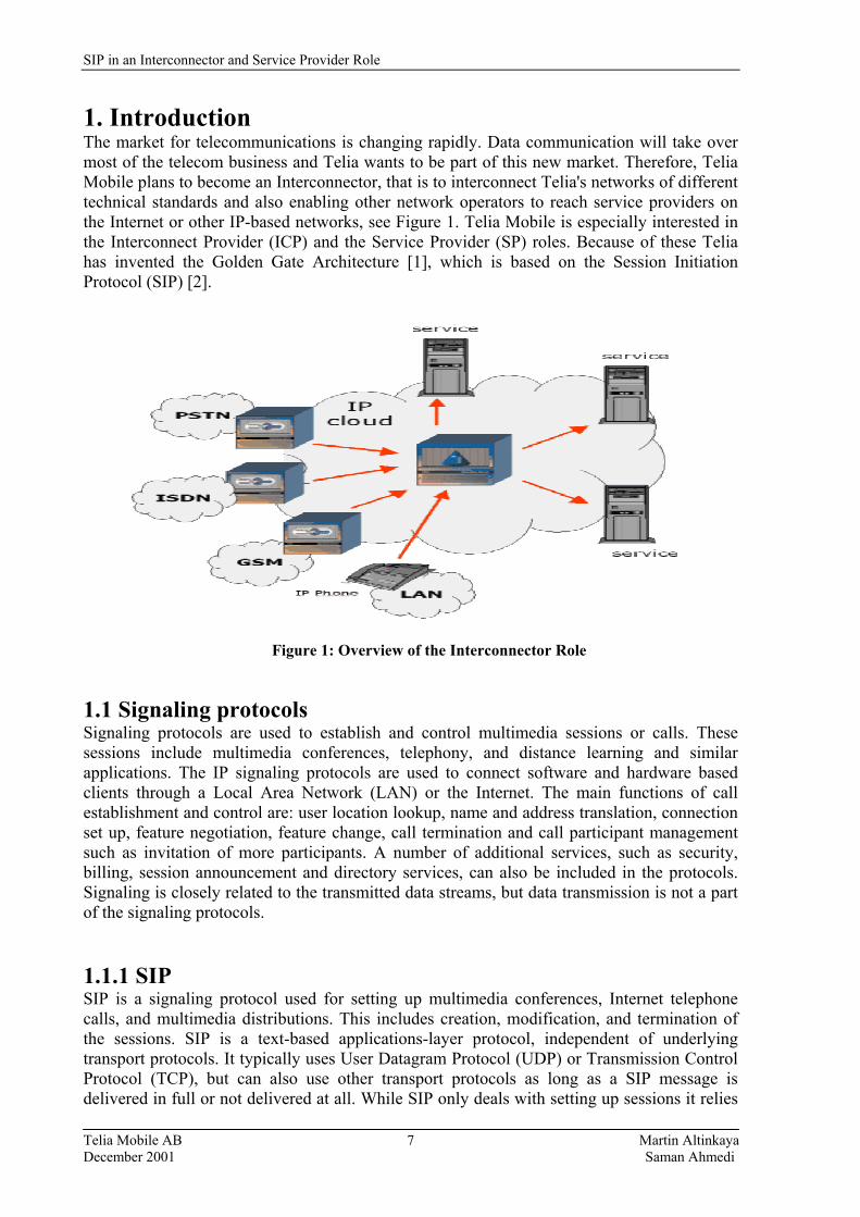
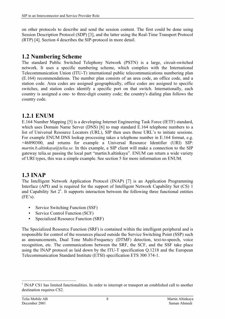
1. Introduction The market for telecommunications is changing rapidly. Data communication will take over most of the telecom business and Telia wants to be part of this new market. Therefore, Telia Mobile plans to become an Interconnector, that is to interconnect Telia's networks of different technical standards and also enabling other network operators to reach service providers on the Internet or other IP-based networks, see Figure 1. Telia Mobile is especially interested in the Interconnect Provider (ICP) and the Service Provider (SP) roles. Because of these Telia has invented the Golden Gate Architecture [1], which is based on the Session Initiation Protocol (SIP) [2].
Figure 1: Overview of the Interconnector Role
1.1 Signaling protocols Signaling protocols are used to establish and control multimedia sessions or calls. These sessions include multimedia conferences, telephony, and distance learning and similar applications. The IP signaling protocols are used to connect software and hardware based clients through a Local Area Network (LAN) or the Internet. The main functions of call establishment and control are: user location lookup, name and address translation, connection set up, feature negotiation, feature change, call termination and call participant management such as invitation of more participants. A number of additional services, such as security, billing, session announcement and directory services, can also be included in the protocols. Signaling is closely related to the transmitted data streams, but data transmission is not a part of the signaling protocols. 1.1.1 SIP SIP is a signaling protocol used for setting up multimedia conferences, Internet telephone calls, and multimedia distributions. This includes creation, modification, and termination of the sessions. SIP is a text-based applications-layer protocol, independent of underlying transport protocols. It typically uses User Datagram Protocol (UDP) or Transmission Control Protocol (TCP), but can also use other transport protocols as long as a SIP message is delivered in full or not delivered at all. While SIP only deals with setting up sessions it relies
SIP in an Interconnector and Service Provider Role
Telia Mobile AB Martin Altinkaya December 2001 Saman Ahmedi
8
on other protocols to describe and send the session content. The first could be done using Session Description Protocol (SDP) [3], and the latter using the Real-Time Transport Protocol (RTP) [4]. Section 4 describes the SIP-protocol in more detail. 1.2 Numbering Scheme The standard Public Switched Telephony Network (PSTN) is a large, circuit-switched network. It uses a specific numbering scheme, which complies with the International Telecommunication Union (ITU-T) international public telecommunications numbering plan (E.164) recommendations. The number plan consists of an area code, an office code, and a station code. Area codes are assigned geographically, office codes are assigned to specific switches, and station codes identify a specific port on that switch. Internationally, each country is assigned a one- to three-digit country code; the country's dialing plan follows the country code. 1.2.1 ENUM E.164 Number Mapping [5] is a developing Internet Engineering Task Force (IETF) standard, which uses Domain Name Server (DNS) [6] to map standard E.164 telephone numbers to a list of Universal Resource Locators (URL), SIP then uses those URL�s to initiate sessions. For example ENUM DNS lookup processing takes a telephone number in E.164 format, e.g. +46890300, and returns for example a Universal Resource Identifier (URI) SIP: [email protected]. In this example, a SIP client will make a connection to the SIP gateway telia.se passing the local part �martin.b.altinkaya�. ENUM can return a wide variety of URI types, this was a simple example. See section 5 for more information on ENUM. 1.3 INAP The Intelligent Network Application Protocol (INAP) [7] is an Application Programming Interface (API) and is required for the support of Intelligent Network Capability Set (CS) 1 and Capability Set 21. It supports interaction between the following three functional entities (FE�s).
• Service Switching Function (SSF) • Service Control Function (SCF) • Specialized Resource Function (SRF)
The Specialized Resource Function (SRF) is contained within the intelligent peripheral and is responsible for control of the resources placed outside the Service Switching Point (SSP) such as announcements, Dual Tone Multi-Frequency (DTMF) detection, text-to-speech, voice recognition, etc. The communications between the SRF, the SCF, and the SSF take place using the INAP protocol as laid down by the ITU-T specification Q.1218 and the European Telecommunication Standard Institute (ETSI) specification ETS 300 374-1.
1 INAP CS1 has limited functionalities. In order to interrupt or transport an established call to another destination requires CS2.
SIP in an Interconnector and Service Provider Role
Telia Mobile AB Martin Altinkaya December 2001 Saman Ahmedi
9
One of the difficulties for Golden Gate Architecture is that there is no direct correspondence between INAP- and SIP-operations, because SIP is a signaling protocol and not an API. INAP is described in section 6. 1.4 Quality of Service On the Internet today most of the traffic uses �best effort� transport, which means that the network will do its best, but it gives no guarantees. With the help of protocols such as Differentiated Services (DiffServ) [8], and Resource ReSerVation Protocol (RSVP) [9] there can be a guarantee that the information gets through, but not guarantee when. To be able to charge customers for real-time applications, like IP-telephony, there must be a guarantee that the information will get to its destination in time to provide undisturbed service. Best effort does not give that assurance. The Quality of Service (QoS) issues will be discussed in section 7. 1.5 Charging models As IP-based services increase in number and complexity, flat rate billing model (which is the most common way today) may mean trouble for service providers. Instead of paying based on the time and distance of a connection, customers could be billed based on amount of data, volume or numbers of times a service is used. Packet-Based networks have five types of costs associated with their operation. These costs have to be covered by the users of the services provided by the network. New and modern charging mechanisms, which will be accepted by users, thus need to be introduced to provide for these costs. These costs are: • Fixed costs of providing the network infrastructure, e.g. Links, Switches, Routers etc. • An incremental cost of connecting to the network, i.e. bringing the network to the user.
The user in the form of a connection cost pays this. • Cost of expanding the network capacity. This is borne by users who wish to use the
network when it is congested. Users willing to defer their transmission during congested periods should not pay for this.
• An incremental cost of sending packet. This should be very low, during uncongested periods, since the bandwidth of a broadband network such as General Packet Radio Service (GPRS) and Universal Mobile Telecommunication Systems (UMTS) is a shared resource.
• A social cost, resulting from the fact that the transmission of a packet regularly leads to a delay in other users� packets.
In the Circuit-Switched domain, only the first three costs exist, and possibly also the social cost in networks unable to cater for full capacity. Traditionally, these costs have been condensed into a single price, fixed over long periods of time. They should however be split up into an access charge, a usage charge, a congestion charge, and a QoS charge. Access charges are usual now, were the user is charged for the privilege of accessing the network. These are imposed to cover the fixed costs of running the network. Usage charges are imposed to recover the variable cost of running the network, while congestion charges persuade users to transmit during off-peak periods. All of these exist even in the Circuit-Switched domain. The new charge in the Packet-Switched domain, the QoS charge, arises
SIP in an Interconnector and Service Provider Role
Telia Mobile AB Martin Altinkaya December 2001 Saman Ahmedi
10
from the user willing to pay to receive a certain QoS guarantee. In section 8 we will propose different charging models for service providers to bill their customers in the IP-world, in conjunction with QoS. 1.6 Problem Statements 1.6.1 Main problems with the Golden Gate Architecture Implementation The Golden Gate Architecture is based on translation from Signaling System no 7 (SS7)2 signaling to SIP and vice versa in the Golden Gate-gateway (which is a Session Control Gateway, described in 2.4.1). Via the translation in the gateway an IP-service can control the behavior in the telephone-net. An advantage of this is cheaper services since they can be put into effect in an ordinary Personal Computer (PC). Another advantage of this architecture is that services can be bought from any supplier on the market. There are some problems with the prototype of the Session Control Gateway (SC-gateway). One of the main problems is that INAP supports Interactive Voice Response (IVR), and SIP does not since there is no need of any IVR in the IP-world. IVR allows callers to interact with your communications systems over the telephone to retrieve information from a database, enter information into a database, or both. Interactive voice in the IP-world can be as easy as playing an audio file from a SIP client, who is directly connected to the service application in the SIP server. Another problem is that the management of SIP is not complete with respect to alarm- and error- management. Despite the mentioned problems, the prototype was mainly created as a technical demonstration to prove that such a solution can provide number portability. 1.6.2 What Telia can do to solve those problems The Golden Gate Architecture was proposed by Telia, but the SC-gateway was designed together with Nortel Networks[10] because Telia is not an equipment vendor. Nortel Networks has full control over the software of the gateway, and therefore many of the problems with the prototype can not be solved by Telia themselves. The only thing that Telia can do is to persuade Nortel Networks to further develop the prototype so it can meet the necessary demands. Currently Telia is working with a manufacture to determine the demands on such a product, which would be able to manage translation between INAP/SIP messages. However, such a product doesn�t need to be manufactured by Nortel Networks. Other suppliers can be considered. 1.6.3 Our part in the Golden Gate Project Telia Mobile wants to interconnect Telia´s networks of different technical standards (GSM, W-LAN, PSTN, etc.) and also providing the possibility to enable other network operators to reach service providers on the Internet or on other IP based networks. This document concentrates on the following areas: 2 SS7 is a global standard for telecommunications defined by the International Telecommunication Union (ITU): http://www.itu.int.
SIP in an Interconnector and Service Provider Role
Telia Mobile AB Martin Altinkaya December 2001 Saman Ahmedi
11
• SIP-telephony systems, since Telia´s Golden Gate project is based on SIP. This means that a description of the SIP protocol is given in section 4. How SIP can work together with ENUM functions is addressed in section 6.
• The translation of INAP-messages to SIP-messages (see section 6). As of yet, there are no
solutions which do the translation between these messages and therefore we are going to investigate possible solutions.
• Charging and billing from an Interconnector- and Service Provider view. How should
Telia charge the customers and other network operators for using the services they provide in the Golden Gate Architecture?
1.6.4 Methods To be able to solve the stated problems, we first studied the existing documents about the Golden Gate Architecture at Telia. We have also studied other documents in this area e.g. Internet Drafts and Request For Comments (RFC�s) for the relevant protocols. The method used in this thesis includes review of the progress towards translating INAP-messages to SIP-messages, and an investigation of how SIP can work together with ENUM functions. This thesis does not aim to solve the existing problems with the Golden Gate Architecture Implementation, rather it should provide a framework for future expansion the Golden Gate Architecture. This thesis should also result in a couple of suggestions of different types of charging models, in order that Service Providers would get paid for their services. The evaluation should also offer some conclusions of how SIP can work together with ENUM and determine if there is solution to the translation problem between SIP-and INAP-messages. 1.6.5 Structure of the document This document is structured in the following way: First, Telia´s Golden Gate is introduced, here the focus is on multi-network services and the Golden Gate architecture. Then a background overview of IP telephony is given, describing the differences between IP telephony calls and PSTN calls, and advantages and challenges of IP telephony. These sections also will introduce and describe the Interconnect and Service Provider roles with respect to the Golden Gate Architecture. The content of this document is outlined in the following way, section 4 describes the Session Initiation Protocol. Section 5 explains ENUM and ENUM/SIP interworking. Section 6 explains INAP and the translation of INAP/SIP-messages. Section 7 describes the QoS issues, section 8 deals with Charging/billing-methods for IP-telephony followed by conclusions in section 9. Then in section 10 the report take a brief look at the future and what future work may contain.

SIP in an Interconnector and Service Provider Role
Telia Mobile AB Martin Altinkaya December 2001 Saman Ahmedi
12
2. Multi-network services Telia's Golden Gate project provides a new way to create multi-network services, i.e. services that are available to a user regardless of which network the caller and the callee are connected to. Multi-network services have until now only been developed in one of three ways: • Via a network specific copy of the service for each network. This solution involves
multiple production systems and a lot of code to create and maintain, along with potential replication problems.
• Route all inbound (or outbound) calls to (from) a subscriber via a service node in one of
the networks. This solution suffers from poor network efficiency and lots of telephony gateways are needed.
• Put the service on top of a service platform (soft switch) in a node that does not belong to
a particular network, but by means of interfaces we can control the routing of calls in each of the networks. A network-independent API eliminates the need for services to behave in specific ways depending on which network the call is being made in. This solution has a substantial hazard of being dependent on a single platform vendor due to vendor-flavored APIs.
2.1 Introduction to Telia´s Golden Gate Architecture The Telia Golden Gate Architecture (shown in figure 2) was developed to provide a flexible choice for operators and customers in the telecom marketplace. It was first developed to provide number portability from any type of network to any other type of network. It also provides a good business base for both service providers and consumers. The result is an Internet-based service solution for both circuit- and packet networks. The Golden Gate Architecture addresses three dimensions: Business, Information, and telecom technology, and bridges them together. Instead of using different APIs to access each platform, the Golden Gate uses SIP for interconnecting each of the networks with the services attached to the Internet. The Golden Gate node hides from the services the fact that not all networks support SIP, hence enabling the services to behave the same way regardless of in which network the call is being made to or from. The SIP messages are translated in the Golden Gate node to SS7 messages for PSTN. Golden Gate can be made to support any protocol used for routing calls through a circuit-switched network, e.g. INAP, MAP[11] and ISUP[12]. Translation of messages to/from SIP into these protocols are not easy and nobody has fully succeeded in doing this, although many Internet-workgroups are trying to solve this problem (e.g. PINT[24] and SPIRITS[23]). However, most messages of each of these protocols can be handled, thus useful services can already be provided, one of these is number portability which means the �phone number� is no longer tied to a specific operator nor to a geographic area.
SIP in an Interconnector and Service Provider Role
Telia Mobile AB Martin Altinkaya December 2001 Saman Ahmedi
13
2.2 Protocol definitions 2.2.1 INAP Intelligent Network Application Part (INAP) defines the service layer call states in SS7 and enables network elements to communicate with Intelligent Peripherals (application service nodes such as voice messaging and calling card systems). 2.2.2 MAP Mobile Application Part (MAP) messages sent between mobile switches and databases to support user authentication, equipment identification, and roaming are carried by Transaction Capabilities Application Part (TCAP)[13]. In mobile networks, when a mobile subscriber roams into a new mobile switching center area, the integrated visitor location register requests service profile information from the subscriber's Home Location Register (HLR) using MAP information carried within TCAP messages. 2.2.3 ISUP The ISDN User Part (ISUP) defines the protocol and procedures used to set-up, and release trunk circuits that carry voice and data calls over the PSTN. ISUP is used for both Integrated Services Digital Network (ISDN) and non-ISDN calls. 2.3 Business Architecture The business dimension is divided into six major parts corresponding to business roles. These are (1) Providers of Terminals, (2) Transmission, (3) Networks, (4) Interconnect, (5) Service and (6) Customer Context. The first three are �traditional� roles�. In this master thesis we will only concentrate on the Interconnect- and Service Provider roles, see Figure 2. Interconnect Provider: The Interconnector is the heart of the Golden Gate. It utilizes an address/number database and also acts as a broker for services and networks, which means that service providers can connect their services to any network they want (see Figure 1). As it is IP-based you can provide the services in the place or country you find best. Service Provider: The Service Provider role will be largely independent of networks. With the help of Golden Gate, services can be connected to any network, whether they are mobile, fixed, LAN, broadband, or new networks like UMTS, without any change to the service. This will reduce costs significantly for development, maintenance, and production of services. 2.4 Technical Architecture The Golden Gate is constructed with Internet components, which makes it cost effective and flexible. The current circuit switched networks are connected to gateways, which enables them to co-operate with packet networks and the services. This means that you can utilize the traditional networks and exploit the huge investments in them, while at the same time utilize them together with the new Internet networks and Internet based services.

SIP in an Interconnector and Service Provider Role
Telia Mobile AB Martin Altinkaya December 2001 Saman Ahmedi
14
Context Provider Cutomer Business Product PC PCs SIP linked Service Provider Value-added Services Services Network Address Golden Gate New services Customer Product Interconnect Adress & Number Provider Service Network & Service Broker Network Adress Network Operator GSM PSTN GPRS
Figure 2: The roles of the Interconnector and Service Provider 2.4.1 Session Control Gateway Telia´s Golden Gate project has invented a new type of gateway between PSTN and an IP network. This gateway makes that a Service Switching Point (SSP) in PSTN can be controlled by a service built on top of SIP-servers in IP networks. These SIP-servers can be outspread over the Internet. The SIP sessions think that they control an ordinary session between two SIP-terminals, which is not the case. The concept makes that a SIP-service, which is developed for IP networks, even can control calls in the PSTN without need of reprogramming. This type of gateway is called Session Control Gateway (SC-gateway). The SC-gateway reflects the situation in PSTN to a corresponding situation in the SIP-world. For example, if you dial ´1234´ from a PSTN phone, the SC-gateway makes the service think that someone dial ´1234´ from a SIP phone. A SC-gateway analyzes the answer from the SIP service and decides if the call can be connected in the PSTN. If that is the case, the path of the call does need to be connected via a telephone gateway. If the call-destination is located in the IP network the call is controlled by the SC-gateway via a telephony gateway. Connection via a telephony gateway can only be made when the endpoints are located in different type of networks such as the PSTN and an IP network. An advantage with this is that Intelligent Network-services (IN-Services) can be developed faster and cheaper. This IN services can be executed anywhere on the Internet. (IN-services are described in section 6.1.2.1).
Business Architecture Information Architecture
Technical Architecture
Database
Number/address
GW GW GW

SIP in an Interconnector and Service Provider Role
Telia Mobile AB Martin Altinkaya December 2001 Saman Ahmedi
15
2.5 Information Architecture The information dimension corresponds to the business roles. Today services are implemented by software in computers, thus the administrative components and the telecom-related functions all become services that can be called upon by any node with an IP-address.

SIP in an Interconnector and Service Provider Role
Telia Mobile AB Martin Altinkaya December 2001 Saman Ahmedi
16
3. Introduction to IP-Telephony As the popularity of the Internet has risen, the market demand for technologies, such as IP telephony3, that enable the convergence of this new medium of communication with the more traditional media has also increased. IP telephony is a technology that functions today. Demos have been made, calls have been made, and there are commercially available copies of IP telephony systems (servers and client agents) that can be bought or downloaded for free on the Internet. IP-telephony reduces infrastructure investments and enables new services. The challenge of IP telephony today is to make the technology available for a broad market, because the QoS is not yet good enough to replace the PSTN and a way to charge the customer for use services must be developed. With IP telephony voice and fax calls are transmitted over an IP network such as the Internet, rather than over the PSTN. During the last four years IP telephony has become a hot topic and at the moment it seems that IP telephony will revolutionize both the voice call business and the technology used to transport voice calls. Since access to the Internet is available at local phone connection rates, international or other long-distance calls will be much less expensive than through the traditional call arrangement. 3.1 IP-Telephony The primary technical difference between the Internet and the PSTN is their switching architecture. The Internet uses dynamic routing whilst the PSTN uses static switching. Another major difference is that PSTN is based on synchronous clocking, i.e., an operator�s entire network is synchronized with a single clock. The PSTN is a circuit switched network. It dedicates a fixed amount of bandwidth for each call and thus a specific quality of service is guaranteed. When the caller places a typical voice call, he picks up the phone and hears the dial tone or perhaps a message indicating there is no capacity. If there is a dial tone, then he dials the (optional) country code, area code, and the number of the extension he wants to reach. The central office will establish the connection, and then the caller and callee can communicate with each other. The channel is occupied regardless of whether they talk or not. This means that the infrastructure is sometimes used poorly and a lot of bandwidth may be wasted (typically more than 50%). When the caller places an IP telephony call from an office phone, he picks up the phone and hears a dial tone from the Private Branch Exchange (PBX) assuming a line is available (PBX provides phone services and access to the PSTN). Then he dials a number, which is forwarded to the nearest IP telephony gateway located between the PBX and the TCP/IP network. The IP telephony gateway finds a route through the Internet that reaches the called number, see Figure 3. Then the call is established. The IP telephony gateway encodes voice samples into IP packets and sends them over the TCP/IP network as data packets. Upon receiving the IP encoded voice packets, the remote IP telephony gateway decodes them into analog signals for the callee through the PBX. This procedure means that there is no channel between the caller and the called during the time of their call, as in the case with the circuit 3 The ITU defines IP telephony as a general term that encompasses two subsets: (1) Voice over IP (VoIP) � used to describe IP telephony where principal transmission networks are private, managed IP-based networks; and (2) Internet telephony � used to describe IP telephony where the principal transmission network is the public Internet.
SIP in an Interconnector and Service Provider Role
Telia Mobile AB Martin Altinkaya December 2001 Saman Ahmedi
17
switched technology. This implies that when packet switched technology is used a larger number of calls could be handled by the infrastructure within a given bandwidth at the same time. As bandwidth is used more efficiently, cost saving is one of the pleasant results for an operator when using IP telephony.
sa a sa sa
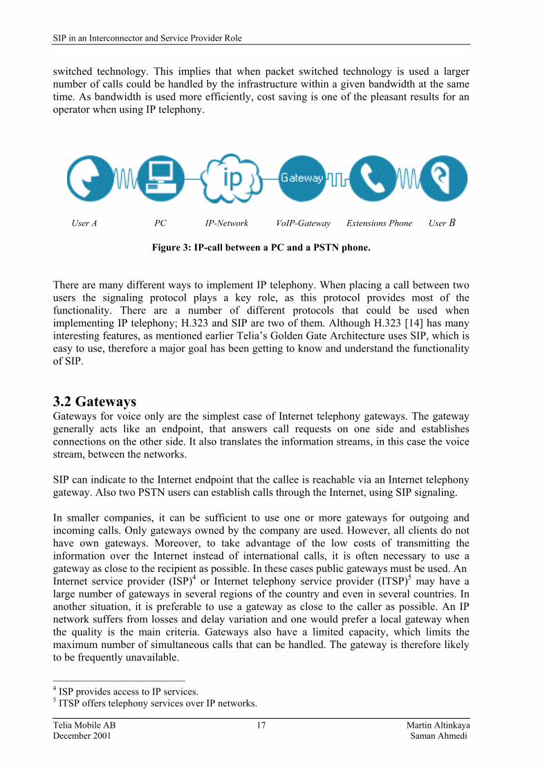
User A PC IP-Network VoIP-Gateway Extensions Phone User B
Figure 3: IP-call between a PC and a PSTN phone. There are many different ways to implement IP telephony. When placing a call between two users the signaling protocol plays a key role, as this protocol provides most of the functionality. There are a number of different protocols that could be used when implementing IP telephony; H.323 and SIP are two of them. Although H.323 [14] has many interesting features, as mentioned earlier Telia�s Golden Gate Architecture uses SIP, which is easy to use, therefore a major goal has been getting to know and understand the functionality of SIP. 3.2 Gateways Gateways for voice only are the simplest case of Internet telephony gateways. The gateway generally acts like an endpoint, that answers call requests on one side and establishes connections on the other side. It also translates the information streams, in this case the voice stream, between the networks. SIP can indicate to the Internet endpoint that the callee is reachable via an Internet telephony gateway. Also two PSTN users can establish calls through the Internet, using SIP signaling. In smaller companies, it can be sufficient to use one or more gateways for outgoing and incoming calls. Only gateways owned by the company are used. However, all clients do not have own gateways. Moreover, to take advantage of the low costs of transmitting the information over the Internet instead of international calls, it is often necessary to use a gateway as close to the recipient as possible. In these cases public gateways must be used. An Internet service provider (ISP)4 or Internet telephony service provider (ITSP)5 may have a large number of gateways in several regions of the country and even in several countries. In another situation, it is preferable to use a gateway as close to the caller as possible. An IP network suffers from losses and delay variation and one would prefer a local gateway when the quality is the main criteria. Gateways also have a limited capacity, which limits the maximum number of simultaneous calls that can be handled. The gateway is therefore likely to be frequently unavailable.
4 ISP provides access to IP services. 5 ITSP offers telephony services over IP networks.
SIP in an Interconnector and Service Provider Role
Telia Mobile AB Martin Altinkaya December 2001 Saman Ahmedi
18
3.3 Challenges of IP-Telephony Since IP packets carrying voice are treated just like IP packets carrying any other type of data, they are subjected to the same delays, loss, and retransmissions as any other packets. This is especially true when the network is congested; which means that the quality of service becomes a very important issue if there is a risk for network congestion. IP telephony is facing the following challenges [15]: • Unpredictable service quality which concerns both quality of service and reliability. Real
time applications place high requirements on the reliability and quality of service capabilities of IP networks. Protocols and techniques to ensure QoS must be utilized. Until these techniques are widely deployed and supported by most networks, over-provisioning or private IP networks remain the only way to ensure the required QoS.
• Lack of interoperability because a single standard does not exist. There are several
competing or partially overlapping standard proposals as mentioned (i.e., H.323 and SIP). Current IP telephony standards only ensure interoperability within a single IP telephony subnetwork. The communication between gateways or gatekeepers from different vendors still remains to be standardized.
• Regulatory development will have a major impact on IP telephony. In most countries IP
telephony is still unregulated but the regulatory authorities are monitoring the situation closely.
• Inertia in the legacy networks, large investments tied in legacy technologies, and people
are accustomed to the old services.

SIP in an Interconnector and Service Provider Role
Telia Mobile AB Martin Altinkaya December 2001 Saman Ahmedi
19
4. Session Initiation Protocol (SIP) 4.1 Introduction The Session Initiation Protocol (RFC2543, [2]) is an application-layer control protocol for creating, modifying and terminating sessions with one or more participants. These sessions include Internet multimedia conferences, Internet telephone calls and multimedia distribution. Members in a session can communicate via multicast or via a mesh of unicast relations, or a combination of them. SIP invitations are used to create sessions and carry session descriptions, which allow participants to agree on a set of compatible media types. SIP supports user mobility by proxying and redirecting requests to the users current location. Users can register their current location. SIP is not tied to any particular conference control protocol and is designed to be independent of the lower-layer transport protocol and can also be extended with additional capabilities. A list of SIP definitions can be found in Appendix A. SIP is a protocol developed to assist in providing advanced telephony services across the Internet. Internet telephony is evolving from its use as a cheap (but low quality) way to make international phone calls to a serious business telephony capability. SIP is one of a group of protocols required to ensure that this evolution can take place. A SIP message is either a request from a client to a server, or a response from a server to a client. SIP uses message structures used by HyperText Transfer Language (HTML). The messages are in text format using International Standards Organization (ISO) 10646 in UTF-8 encoding. As in HTML the client requests invoke methods on the server. The messages consists of a start-line specifying the method and the protocol, a number of header fields specifying call properties, service information, and an optional message body which can contain a session description. The following methods are applicable in SIP: INVITE Invites a user to join a call. BYE Terminates the call between two of the users on a call. OPTIONS Requests information on the capabilities of a server. ACK Confirms that a client has received a final response to an INVITE. CANCEL Ends a pending request, but does not end the call. REGISTER Provides the map for address resolution, letting a server know the
location of other users. The syntax of response codes are similar to HTML. The three digit codes are hierarchically organized with the first digit representing the result class and the other two digits providing additional information. The first digit controls the protocol operation and the other two gives useful but non-critical information. A textual description and even a whole HTML document can be attached to the result message. In SIP the extensibility of functionality has same approach as HTTP and SMTP use. New headers can be added to the SIP messages. Unknown headers and values are ignored by default. Using Require header, the client can require specific headers to be understood by the other endpoint. If it does not support the named services an error message containing the unknown feature is returned and the client can return to a simpler operation. Appendix B describes the different SIP-message headers.

SIP in an Interconnector and Service Provider Role
Telia Mobile AB Martin Altinkaya December 2001 Saman Ahmedi
20
SIP is part of The IETF standards process and is modeled upon other Internet protocols such as SMTP (Simple Mail Transfer Protocol) and HTTP (Hypertext Transfer Protocol). It is used to establish, change and tear down (end) calls between one or more users in an IP-based network. Section 4.6 describes the Session Description Protocol, and section 4.7 a short description of RTP (Real-Time Transport Protocol), a protocol to carry voice and video data. 4.2 SIP Components There are two components within SIP - the SIP User Agent and the SIP Network Server. The User Agent is effectively the end system component for the call and the SIP Server is the network device that handles the signaling associated with multiple calls. The User Agent itself has a client element, the User Agent Client (UAC) and a server element, the User Agent Server (UAS). The client element initiates the calls and the server element answers the calls. This allows peer-to-peer calls to be made using a client-server protocol. The SIP server element also provides for more than one type of server. There are effectively three forms of server that can exist in the network, the SIP stateful proxy server, the SIP stateless proxy server and the SIP redirect server. The main function of the SIP servers is to provide name resolution, and user location, since the caller is unlikely to know the IP address or host name of the called party. What will be available is perhaps an email-like address or a telephone number associated with the called party. Using this information, the caller's user agent can identify with a specific server to resolve the address information- it is likely that this will involve many servers in the network. A SIP proxy server receives requests, determines where to send them, and passes them on to the next server (using next hop routing principals). There can be many server hops in the network. The difference between a stateful and stateless proxy server is that a stateful proxy server remembers the incoming requests it receives, along with the responses it sends back and the outgoing requests it sends on. A stateless proxy server forgets all information once it has sent on a request. This allows a stateful proxy server to fork requests to try multiple possible user locations in parallel and only send the best responses back. Stateless proxy servers are most likely to be the fast, backbone of the SIP infrastructure. Stateful proxy servers are then most likely to be the local devices close to the User Agents, controlling domains of users and becoming the prime platform for the application services. A redirect server receives requests, but rather than passing these onto the next server it sends a response to the caller indicating the address for the called user. This provides the address for the caller to contact the called party at the next server directly. Figure 4 shown all involved components in a SIP communication.

SIP in an Interconnector and Service Provider Role
Telia Mobile AB Martin Altinkaya December 2001 Saman Ahmedi
21
Redirect Server Location Server 2 3 5 6 4 7
SIP Proxy 9 SIP Poxy 8 User Agent (Callee) Request 1 10 Request Response
User Agent (Caller)
Figure 4: SIP communication flow
4.2.1 SIP-session The SIP sessions are set up by using a three-way handshake procedure, similar to TCP [RFC793], see Figure 5. When a Client A wants to set up an IP-telephony session with Client B, A sends an INVITE (1) request to B. In order to find out where to send the INVITE message, it is first necessary to find out which SIP server is responsible for a particular user [RFC2543- section 1.4.2]. Now that the caller knows where the callee is located, the callee can be at several locations at the same time. The INVITE message contains a payload with a description of the session Client A wants to set up with Client B. If it is an IP-telephony session that is about to be set up, then the session description contains information about which audio encoding types. A can understand and it also specifies on which port A wants the RTP audio data sent to. The protocol to convey session description is called the SDP. It is not mandatory for SIP to use SDP, but it is the only one defined so far. Client A INVITE (1) Client B 200, OK (2) ACK (3) Session (4)
Figure 5: SIP- Call Set-up, similar to the three handshake in TCP

SIP in an Interconnector and Service Provider Role
Telia Mobile AB Martin Altinkaya December 2001 Saman Ahmedi
22
When B accepts the call his user agent sends a message (2) with a response code of 200. Any 2xx6 response means that a message was successfully received, understood, and accepted. In the response Cilent B adds his codec capabilities under port numbers where he wants A to send his RTP data to. The final part (3) of the three-way handshake occurs when A sends an acknowledgement to B. By sending an ACK the caller confirms that it has received the response from the callee. The conversation can begin directly after the set up is completed (4). 4.3 Addressing and Naming To be invited and identified, the called party has to be named. Since it is the most common form of user addressing in the Internet, SIP chose an email-like identifier of the form user@domain, user@host, user@IP address or phone-number@gateway. The identifier can refer to the name of the host that a user is logged in at the time, an email address or the name of a domain-specific name translation service. SIP provides its own reliability mechanism and is therefore independent of the packet layer and only requires an unreliable datagram service. SIP uses these addresses as part of SIP URLs, such as sip: user@domain. This URL may well be placed in a web page, so that clicking on the link initiates a call to that address, similar to a mail URL today. We anticipate that most users will be able to use their email address as their published SIP address. Email addresses already offer a basic location-independent form of addressing, in that the host part does not have to designate a particular Internet host, but can be a domain, which is then resolved into one or more possible domain mail server hosts via DNS mail exchange records. For email, finding the mail exchange host is often sufficient to deliver mail, as the user either logs in to the mail exchange host or uses protocols such as the Internet Mail Access Protocol (IMAP) or the Post Office Protocol (POP) to retrieve their mail. For interactive audio and video communications, however participants are typically sending and receiving data on the workstation, PC or Internet appliance in their immediate physical proximity. Thus, SIP has to be able to resolve name@domain to user@host. A user at a specific host will be derived through zero or more translations. A single externally visible address may well lead to a different host depending on time of day, media to be used, etc. Also, hosts that connect via dial modems may acquire a different IP address each time. 4.4 Description of the requests 4.4.1 INVITE The INVITE request is used to set up a session of any kind between two users. It must contain data about between whom the session is to be set up, i.e. To -and From header, and a unique identifier for the session, the CAll-ID -and CSeq-headers. An example of an INVITE message is shown in Figure 6: 6 See Appendix C, SIP Response Messages.

SIP in an Interconnector and Service Provider Role
Telia Mobile AB Martin Altinkaya December 2001 Saman Ahmedi
23
Figure 6: Typical INVITE message with SDP message body The INVITE message can, when arriving at the proxy server, be forked. This means that if the user is registered at more than one address and wants to be reached at all addresses, and an invite will be sent to all registered addresses. The proxy server will add a unique tag to each Via header to be able to know which address that is answering. The INVITE message must often include an SDP message in the message body, where the calling part defines what kind of session it wants to set up and where the media part should be contacted. However, it is not compulsory to send the SDP in the INVITE, it may be sent in the ACK instead. 4.4.2 ACK The ACK request confirms that the client has received a final response to an INVITE request (ACK is used only with INVITE requests). 2xx responses are acknowledged by client user agents, all other final responses by the first proxy or client user agent to receive the response. The Via is always initialized to the host that originates the ACK request, i.e., the client user agent after a 2xx response or the first proxy to receive a non-2xx final response. The ACK request is forwarded as the corresponding INVITE request, based on its Request-URI. The ACK request may contain a message body with the final session description to be used by the callee. If the ACK message body is empty, the callee uses the session description in the INVITE request. A proxy server receiving an ACK request after having sent a 3xx, 4xx, 5xx, or 6xx response must make a determination about whether the ACK is for itself, or for some user agent or proxy server further downstream. This determination is made by examining the tag in the To field. If the tag in the ACK To-Header field matches the tag in the To-Header field of the response, and the From, CSeq and Call-ID header fields in the response match those in the ACK, the ACK is meant for the proxy server. Otherwise, the ACK should be proxies downstream as any other request.
INVITE sip: [email protected]:5060 SIP/2.0 Via: Sip/2.0/UDP 130.237.14.101:5060 From sip [email protected]:5060 To sip: [email protected]:5060 Contact: sip : 130.237.14.101:5060 Call-ID [email protected] CSeq: 1 INVITE Content-Lenght:239 Content-Type: application/sdp v=0 o=saman 13645978650862240000 1345978650862240000 IN IP4 192.43.162.91 s=basic Session c=IN IP4 192.43.162.91 t=0 0 m=audio 49188 RTP/AVP 0 a=rtpmap:0 PCMU/8000 a=ptime:60
SIP in an Interconnector and Service Provider Role
Telia Mobile AB Martin Altinkaya December 2001 Saman Ahmedi
24
4.4.3 OPTION The OPTION message is used by the user agents to query a server about its capabilities. The user agent server may, if it thinks it can contact the user, respond to this request with its capability set. It may also return a status reflecting how it would have responded to an invitation e.g. 600 (Busy). 4.4.4 BYE The user agent client uses BYE to indicate to the server that it wishes to release the call. It can be sent from either party of the call and should include the To-, From-, CSeq and Call-ID combination unique for the session. 4.4.5 CANCEL The CANCEL request cancels a pending request with the same To-, From-, CSeq and Call-ID header field values, but does not effect a complete request or existing calls. A user agent or proxy may issue a CANCEL request at any time. A proxy may choose to send a CANCEL to destinations that have not yet return a final response after it has received a final response for one or more of the parallel search requests. A proxy that receives a CANCEL request forwards the request to all destinations with pending requests. 4.4.6 REGISTER The REGISTER request is used to register a user to a specific address with a SIP location server. There are two ways of configuring the location servers that handles the register. One is to let anyone that wants to register them selves register. The other one is to just allow persons already in the database to register. To secure user identities the location server might demand authentication of the user. The user will then be forced to answer an encrypted challenge to prove his identity. This can only be done if the user already existed in the location server database. 4.5 The Session Description Protocol The Session Description Protocol, SDP (RFC2327, [3]), is an underlying protocol that is used by SIP. It is intended for describing multimedia sessions for the purpose of session announcement, session invitation and other forms of multi media session initiation. SDP is the default session description for use with SIP, but it is not required. SDP has three main parameters that need to be negotiated before the media exchange can begin. These are what kind of media (Audio, Video, or both) should be exchanged, how it should be encoded and where it should be delivered. This information is located in different fields of the SDP message7. Each begins with a letter, explaining what the field contains. The set of field types available in SDP is shown in Figure 7, and Appendix D explains the most important fields.
7 See Appendix D, SDP messages.

SIP in an Interconnector and Service Provider Role
Telia Mobile AB Martin Altinkaya December 2001 Saman Ahmedi
25
Figure 7: Example of SDP description 4.6 Real-time Transport Protocol The Real-time Transport Protocol is used to carry data with real-time properties, and the RTP Control Protocol (RTCP) is used to monitor QoS as well as conveying information about the participants in an on-going conference. RTP implementation is often integrated into an application rather than being implemented as a separate protocol layer, see Figure 8. In applications RTP is typically run on top of UDP [RFC768] to make use of its port numbers and checksums. The RTP framework is relatively flexible allowing modifications and tailoring depending on application. Additionally, a complete specification for a particular application will require a payload format and profile specification. The payload format defines how a particular payload is to be carried in RTP. A payload specification defines how sets of payload type codes are mapped into payload formats. Presentation Session Transport Network Link Physical
Figure 8: Locations of RTP and SIP in IP stack
Voice codes: G.732.1 or G.711 Voice codes: PCM,µ-law or GSM
H.323 SIP
RTP/UDP/TCP/RSVP
IP
Ethernet/IEEE 802.xx
---
v=0 o=sahmedi 2890844526 2890842807 IN IP4 130.237.14.114 s=SDP Seminar i=example of the session description protocol u=http://www.e.kth.se/~e97_ahm/ [email protected] (Saman Ahmedi) c=IN IP4 224.2.17.12/127 t= 2873397496 2873404696 a= recvonly m= audio 49170 RTP/AVP 0 m= video 51372 RTP/AVP 31 m= application 32416 udp wb

SIP in an Interconnector and Service Provider Role
Telia Mobile AB Martin Altinkaya December 2001 Saman Ahmedi
26
An RTP session connection consists of defining a pair of destination transport addresses one IP address and UDP port pair, one for RTP and another for RTCP. In the case of a multicast conference the IP address is a class D multicast address. In a multimedia session each medium is carried in a separate RTP session with its own RTCP packets reporting only the quality of that session. Usually additional media are allocated in additional port pairs and only one multicast address is used for the conference.

SIP in an Interconnector and Service Provider Role
Telia Mobile AB Martin Altinkaya December 2001 Saman Ahmedi
27
5. ENUM 5.1 Introduction E.164 Number Mapping (ENUM) is a developing IETF standard (RFC2916, [5]), which uses DNS [6] to map standard E.164 telephone numbers to a list of URLs. ENUM addresses the question of how telephone numbers can be used to access Internet services, enabling not just voice-over-IP, but other communication applications as well. ENUM lets users type a telephone number into a Web browser and find the corresponding URL, e-mail address, or IP address. Among the SIP vendors that have announced ENUM support are Indigo Software [16], Pingtel [17], and 3Com [18]. These companies plan to use ENUM to help initiate IP telephone calls by looking up the Internet resources available for a particular phone number. ENUM can provide a single point of contact for a person's communications devices, including PCs, fax machines, handheld computers, and cell phones. Once the recipient's URL is found, SIP can handle the communications between the two parties over the Internet. ENUM and SIP also can work together in unified messaging and instant messaging applications. This will be explained in section 5.6. ENUM complements SIP by providing look-up features that will come in handy for such functions as 800 and 020- number translations and local number portability. For SIP carriers, ENUM eliminates the need to support a special routing infrastructure that translates between IP addresses and telephone numbers. Telia Mobile doesn�t use ENUM in any area yet. However, they are interested in using ENUM in the Golden Gate architecture as a number lookup, where they can see whether a subscriber has a second service (call forwarding, filtering, blocking etc.) or not. The number lookup is done in the following way: the SIP-server uses ENUM to send a question to the DNS/ENUM database. The database used in the Golden Gate Pilot implementation is a limited type of ENUM. At the database they can see whether the subscriber has another service or not. If the subscriber has another service, a flag will be put in the answer that makes the SIP-server work in proxy-mode, and forwards the request to the next SIP-server (its address is also received by the DNS/ENUM database). If the subscriber doesn�t have a another service the SIP-server will work in Redirect-mode, and answers on the question whether the subscriber has another question or not. This section main purpose is to address how SIP can work together with ENUM functions. We will start with some history and background on ENUM, and continue in section 5.4 with how ENUM is used. Section 5.5 explains the Naming Authority Pointer Records (NAPTR), and section 5.6 explains how ENUM can be used together with SIP. Further, section 5.7 describes the Telephony Routing over IP (TRIP) protocol, and section 5.8 explains shortly how ENUM can be used for IP-billing issues. We will end this section with a brief view in the future role of ENUM in VoIP. 5.2 History The idea for a system to resolve telephone numbers on the Internet began in 1993, with the pioneering work of Marshall Rose and Carl Malamoud in Internet Fax (RFC1529). Their system created a single domain, TPC.INT, through which people could send faxes over the Internet using phone numbers and lookups to the Internet DNS. Though the experiment was
SIP in an Interconnector and Service Provider Role
Telia Mobile AB Martin Altinkaya December 2001 Saman Ahmedi
28
not widely used, it represented one of the first examples of using phone numbers as identifiers on the Internet. In 1997, the IETF began to discuss a more robust and universal approach to telephone number resolution. The IPTEL working group was formed, but the group decided that the time was not yet right to formulate a solution. In late 1999, it became clear that developments in VoIP, and the SIP in particular, mandated solving the numbering problem, and the ENUM working group was born. Its charter is simple, this working group will define a DNS-based architecture and protocols for mapping a telephone number to a set of attributes (e.g. URLs) which can be used to contact a resource associated with that number. 5.3 Background We all use telephone numbers dozens of times a day. With the help of phone numbers we find people, places, and business on the PSTN. Though the Internet has grown exponentially over the past several years, telephone numbering is still the most widely used addressing and naming scheme for communications in the world. The simple fact is that, despite network convergence, there are billions of phones in existence with twelve-digit keypads that will not go away, and yet today cannot easily find and connect to Internet services, whether voice or not. 5.4 How to Use ENUM The goal with ENUM is to establish a global directory that allows users to lookup telephone numbers, receive URL's and identify a number´s associated IP resources. ENUM does a DNS query on a phone number and sends back a list of URL's from the NAPTR (Name Authority Pointer Record). The order of the digits in a traditional E.164 ITU phone number is reversed so the address identifiers are more closely aligned with its Web counterparts: Where a Web site such as www.telia.com has its most general identifier (the .com) on the right side, phone numbers have the general identifier (the area code) on the left and the numbers on the right become more specific. For the system to determine if the number sequence is registered in the ENUM directory, a dot is placed between each digit followed by the proposed ITU DNS domain e164.arpa (Advanced Research Projects Administration). The .arpa domain has been designated to be used for Internet Infrastructure purposes. For example, in the case of a person who wanted to call the office of Telia at +46-8-90300, ENUM would look up the number 0.0.3.0.9.8.6.4 + e164.arpa. The "+" indicates that the number is a complete international telephone number, otherwise known as an E.164 number. When the name is found, ENUM receives the NAPTR records for that particular number and the SIP call can be connected and carried directly over the IP-network. Once the mapping is complete, the ENUM directory can indicate the available services associated with that telephone number. Looking at that particular string of numbers, it may say that there is an HTTP call on www.telia.com via either a SIP or PSTN connection. If PSTN number is not registered in the ENUM directory, the call will be completed via a gateway to the PSTN.

SIP in an Interconnector and Service Provider Role
Telia Mobile AB Martin Altinkaya December 2001 Saman Ahmedi
29
5.5 NAPTR Resource Records The Naming Authority Pointer Records (NAPTR) is defined by RFC2915 [19]. The DNS Resource Records are fields in the DNS that contain information necessary to perform various functions or to find out what servers have authority for a domain. NAPTR records define the service that can be associated with a particular telephone number in ENUM, including SIP VoIP, fax, email, instant messaging, personal web pages, etc. If a SIP phone were performing an ENUM query the NAPTR records might look as shown in Figure 9.
Figure 9: Input and output, to and from DNS Naming Authority Pointer (NAPTR) facilities. The FQDN is submitted, and a range of media-specific resource identifiers is returned.
In this case, the SIP phone or proxy would parse the NAPTR records looking for the service field that contained SIP (the first record returned in the example above). It would ignore all other records (�mailto,� �tel,� etc.), and then issue a SIP INVITE message to sip: [email protected] in order to connect the call. NAPTR records also have Order and Preference fields that permit the client to know what records to process first. The RFC2916 proposes e164.arpa as the single DNS domain, or the �Golden Tree�, for use with ENUM, see Figure 10. This designation may change as a result of ongoing discussions between the ITU, the IETF, and other international organizations involved with ENUM. But there are good reasons why there should be only one domain associated with phone numbers. It is a fundamental characteristic of the DNS that lookups from client applications must follow a single path from the most significant (root) to the least significant part of the Fully Qualified Domain Name (FQDN) in the DNS tree. However each of the levels of the hierarchy tree can use caching. Thus the look up does not need to start at the root server8. e164.arpa was selected so that IP telephones, fax machines, proxies, and gateways would know where to look for relevant data. The .arpa Top-Level Domain (TLD) was chosen because it is under the operational management of the Internet Architecture Board. The .arpa TLD has been designated specifically for Internet infrastructure purposes. For example, .arpa already contains the �IN-ADDR� and �IPv6� domains that are used for reverse IP address to domain name lookup. 8 Even if DNS behaves as if there were a single root, there can be multiple root servers.
Input to the DNS: $ORIGIN. 0.0.3.0.9.8.6.4.e164.arpa Output to the Client: Ord pr fl service re replacement IN NAPTR 10 10 �u� �sip+E2U� �!^.*$!sip:[email protected]!�. IN NAPTR 102 10 �u� �mailto+E2U� �!^.*$!mailto:[email protected]!�. IN NAPTR 102 10 �u� �fax-t37+E2U� �!^*$!mailto:[email protected]!�. IN NAPTR 102 10 �u� �tel+E2U� �!^*$!tel:+46890300!�.

SIP in an Interconnector and Service Provider Role
Telia Mobile AB Martin Altinkaya December 2001 Saman Ahmedi
30
root .com .se .arpa e.164 4.4 (UK) 6.4 (SE)
Figure 10: The �Golden Tree� Given the input in Figure 9, a DNS lookup would start at the .arpa domain and would continue with .e164. Under .e164, it would look for the country code (�46� in the case of the Sweden), and would then look up each succeeding digit in the telephone number until the address can be fully resolved. DNS clients cannot, however, switch top-level domains in the middle of a search, or query multiple top-level domains simultaneously once they have begun to search under a particular TLD. These characteristic makes it difficult to create a practical system in which a client would have to search multiple domains in order to find records associated with one telephone number. For instance, imagine a system where telephone numbers could only be placed in a domain within the country code of that portion of the E.164 namespace. In this scheme, all U.S. telephone numbers would be placed in e164.us and all Swedish numbers in e164.se, etc. Though this might seem reasonable, it in fact creates an intolerable burden on the ENUM client application. Having to analyze the complete dialing string to determine which country code domain to look up in the DNS lookup trying to find the phone- or IP number to call, and also having to maintain a complete list of approved country code domains. The end result would be a whole host of problems for applications, forcing the inclusion of a new set of DNS code, requiring more processing power, and memory to be added to potentially billions of devices existing on the Internet. 5.6 SIP and ENUM Though ENUM can enable any number of services, its importance in voice-over-IP and SIP cannot be underestimated. ENUM makes SIP as simple to use as dialing a telephone number. A user�s telephone number could be used as a �handle� for SIP-based instant messaging, or the telephone number could be used as a way to place and receive real-time voice calls on many of the new SIP networks being deployed globally. A user�s access to these services might be through next-generation SIP phones or PBX systems, or a �softphone� on their PC. ENUM also solves one of the most vexing problems in Internet telephony, which is inter-domain call routing based on a telephone number. This is a problem that has plagued both H.323 and SIP for some time. As it stands now, most VoIP is uses intra-domain or for calling within an enterprise to various remote locations. Vendors have all developed proprietary routing tables in their gateways or proxies that translate the dial string to a host name or URL necessary to set up a call. Before the invention of ENUM, there has been no practical solution to the problem of call setup across these domain boundaries.

SIP in an Interconnector and Service Provider Role
Telia Mobile AB Martin Altinkaya December 2001 Saman Ahmedi
31
The Figure 11 displays one possible voice call flow using an ENUM lookup. In this case, the subscriber has registered for ENUM services using the SIP address sip: name@domain. A query based on the telephone number dialed is sent to the DNS server, who returns the SIP address, and the SIP proxy sets up the call. This is only one of a number of different ways that ENUM can be used to set up a call. It is important to note that ENUM can also be used to enable customized service creation within private dialing plans. Nearly every enterprise or organization maintains some form of four- or five-digit private dialing plan within the context of its PBX. ENUM permits the resolution of private numbering plans in private domains. So in the case of BigCorp Inc., the resolution of internal SIP telephone number 90300 would occur in 0.0.3.0.9.e164. bigcorp.com. The flow of information will remain the same no matter what the application or private domain used, and does not overlap or interfere with any public ENUM service based in e164.arpa.
DNS-Server
Response SIP:[email protected] Query Call Setup 0.0.3.0.9.8.6.4.e164.arpa SIP: [email protected]
Dial: + 46 8 90 300 SIP Proxy SIP Proxy
Figure 11: A DNS query 5.7 TRIP Telephony Routing over IP (TRIP) is an inter-domain gateway location and routing protocol. The TRIP protocol enables reachability of telephone destinations between different Location Servers (LS), and for advertising attributes of the routes to those destinations. The routing details include the reachability of telephony destinations and the gateway and routes to those telephony destinations in the PSTN. TRIP is designed to allow service providers to exchange routing information in order to avoid the over-provisioning or duplication of gateways, Appendix E gives a brief view of TRIP messages. It uses established Internet protocols such as Border Gateway Protocol version 4 (BGP-4) [20] and Open Shortest Path First (OSPF) [21]. TRIP provides following functionality�s [22]: • Establishment and maintenance of peering relationships between Providers. • Exchange and synchronization of telephony gateway routing information between
Providers.
SIP in an Interconnector and Service Provider Role
Telia Mobile AB Martin Altinkaya December 2001 Saman Ahmedi
32
• Prevention of non-stable routes for IP telephony signaling protocols. • Propagation of gateway routing information to other Providers. • Definition of the syntax and semantics of the data, which describe telephony routes from
IP to PSTN. • Essentially a �Phone Number to IP Address� translation mechanism. TRIP is deployed at an IP network's peering points to provide inter-signaling between VoIP protocols. When setting up a VoIP session, TRIP routes a signal to a PSTN Gateway that owns the ENUM database. From there, ENUM gives a list of names that belongs to the particular number on the gateway to which TRIP is trying to connect. Whereas ENUM takes a phone number and locates an address via DNS, in a typical VoIP session, the IP router looks at the IP address and the SIP proxy makes decisions on where to send packets. From there, these proxies take requests sent from the common interdomain IP protocols. TRIP uses the concept of Internet Telephony Administrative Domains (ITAD) in a similar way as BGP uses autonomous systems. The location servers that are administered by a single provider form an ITAD. The ITAD may contain zero or more gateways. The border of the ITAD does not have to correspond to the border of an autonomous system. The main function of TRIP is to distribute information between ITADs, but TRIP also contains functions for inter-domain synchronization of routing information. It is not required that all ITADs in the world are connected. Groups of ITADs can be formed that exchange information via TRIP. 5.8 ENUM and Billing On the Internet, distance related charging does not apply because the sender may not necessarily know where the receivers are, especially in multicast scenario (even in unicast case, IP addresses of hosts do not represent the �geographic distances� between each other). Therefore, a video conferencing that is taking place between a host on the Internet to a PSTN phone-set or another host on the Internet becomes difficult to charge. There are mainly three types of billings that can take place for a conference: • PC to PC billing • PC to phone billing • Phone to PC billing The physical location of a PC on the Internet cannot be used to price the connection that takes place in either of the above cases. If it is a PSTN to IP pricing (last case) scenario, then the user will pay the local phone company for using the service and it is up to the phone company to locate the IP telephony gateway and complete the call. The gateways can then use the �dial plan� to price the call that takes place from the gateway (end of PSTN) to the PC (over IP). So for example, if user A wants to videoconference to a machine named B, then B must have an assigned e164 number or the user might start by calling an access number (which is perhaps local) such as +46 8 90300 and then enter the IP address of the machine using the numbers in place of the decimal points in the dotted-decimal format of machine B's IP address. Therefore the caller will be charged accordingly. Charging and billing in IP telephony is discussed in section 8.

SIP in an Interconnector and Service Provider Role
Telia Mobile AB Martin Altinkaya December 2001 Saman Ahmedi
33
5.9 ENUM�s role in the future of VoIP ENUM will play a great role in the future of VoIP, not just for its resolution purposes, but as an enabling technology to allow the deployment of new applications. These new services will be one of the driving forces in the VoIP market.
SIP in an Interconnector and Service Provider Role
Telia Mobile AB Martin Altinkaya December 2001 Saman Ahmedi
34
6. Intelligent Networks This section gives input on the SIP/IN Interworking Protocol Architecture and Procedures. The aim of the SIP/IN Interworking is to consider the support of existing IN-based applications in a SIP-based IP environment for IP-Host-to Phone calls. This section is organized as follows. Section 6.1 gives an introduction to Intelligent Networks. Section 6.2 describes the Intelligent Network Application Protocol (INAP), and section 6.3 gives a short description of the underlying SS7 protocols. Section 6.4 explains the proposed IETF architecture model for SIP/IN interworking, and finally, section 6.5 describes the Registration process relating to Originating and Terminating calls. How the Originating and Terminating Basic Call State Model Points in Call and Detection Points are mapped to the appropriate SIP messages are not explained here. Instead we refer the interested reader to ongoing projects by ETSI. An Internet Draft that discusses the SIP/IN interworking can be accessed at ftp://ftp.nordu.net/internet-drafts/draft-haerens-sip-in-01. 6.1 Introduction 6.1.1 SS7 Overview SS7 (Signaling System no. 7) is the common signaling protocol used for call handling within the telephone network and as the basis of Intelligent Network (IN). It is the underlying data communications protocol used by telephone networks to control call set-up and call routing. SS7 was originally designed for exchanging call control information between the various network switches and databases of the PSTNs, and was increasingly used for enabling the deployment of new technologies such as Integrated Services Digital Network (ISDN). ISDN uses signaling systems to support intelligent network services. The SS7 protocol standard are international and have been adopted and published by ITU in the Q.700 series. 6.1.2 Intelligent Network Overview The IN refers to architecture for implementing intelligence and advanced functionality within the telephone network. IN infrastructure is used by many telephone services. The idea of the IN is to have a centralized service control structure, and to keep the logic in a few centralized computing nodes. This separates the service processing from the basic call control and switching, i.e. the service provider only has to update the software in the computing node when they want to introduce a new service, rather that need to update every single switching node. This was expected to enable faster service creation and deployment. Key elements of the Intelligent Network include: • Service Switching Points (SSP): these signaling points are the originators and terminators
of signaling messages, such as local Central Offices (CO) or exchanges. • Service Control Points (SCP): these signaling points are typically databases, such as the
HLR in a wireless network. The program running on the SCP, which determines how the call should be handled, is referred to as the Service Logic Program (SLP).
• Signal Transfer Points (STP): these signaling points are the SS7 packet switches, or routers, which route traffic through the SS7 network.

SIP in an Interconnector and Service Provider Role
Telia Mobile AB Martin Altinkaya December 2001 Saman Ahmedi
35
• Intelligent Peripheral: these IN network elements provide services which facilitate customer interaction such as voice prompting, voice storage, and fax storage.
• Adjunct: these IN network elements provide customer service functions through the CO Switch.
6.1.2.1 IN Based Services The IN can be used as a basis for many interesting telecom services such as following: • Virtual Private Network (VPN): VPN enables the possibility of using only abbreviated
phone numbers to reach those who is connected to the same VPN. For example, with a short number one can reach a colleague not only inside the same office, but also colleagues in other branch offices around the world.
• Prepaid call: This service allows the user to charge any calls made to a special prepaid account. The user dials the prepaid access number, enters the card number and the associated PIN code and dials the number he wants to be connected to.
• Do not disturb: You can filter the calls that you don�t want to receive. • Mass calling service: Enable a large number of callers to simultaneously call the same
number and be connected to announcement devices. This is used in many Tele-voting programs.
6.2 Protocol Architecture for SIP/IN The INAP protocol [7] architecture is based on the Open Systems Interconnection (OSI) Application Layer Structure (Figure 12). INAP: Intelligent Network Application Part TCAP: Transaction Capability Applications Protocol SCCP: Signaling Connection Control Part Basic SS7-levels MTP: Message Transfer Part
Figure 12: INAP on top of the SS7
The INAP protocol allows applications to communicate between various nodes/functional entities of an intelligent network. The protocol defines the operations required between nodes/functional entities for providing Intelligent Network services. INAP handles a number of services such as number translation, time of day, follow me, etc. To be able to use the services that INAP offers, a translation from/to INAP is required. But this is not as simple as it sounds. First, the relevant SS7 messages are not standardized and the application layer protocol INAP is far from being standardized, since there exist both country flavored and vendor flavored versions of INAP. The fields for the data used may differ by country and even by operator, so another operator might not be able to read the data properly. The large operators around the world have switches that do the protocol conversion between the other
INAP
TCAP
SCCP
MTP
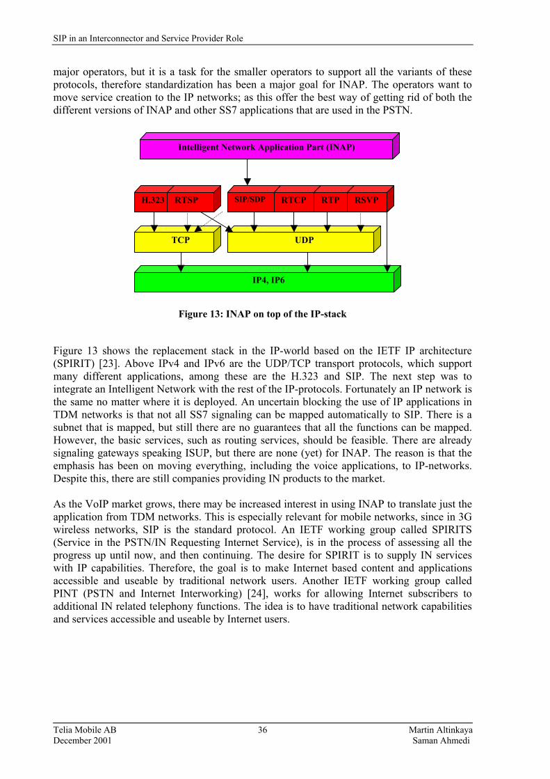
SIP in an Interconnector and Service Provider Role
Telia Mobile AB Martin Altinkaya December 2001 Saman Ahmedi
36
major operators, but it is a task for the smaller operators to support all the variants of these protocols, therefore standardization has been a major goal for INAP. The operators want to move service creation to the IP networks; as this offer the best way of getting rid of both the different versions of INAP and other SS7 applications that are used in the PSTN.
Figure 13: INAP on top of the IP-stack
Figure 13 shows the replacement stack in the IP-world based on the IETF IP architecture (SPIRIT) [23]. Above IPv4 and IPv6 are the UDP/TCP transport protocols, which support many different applications, among these are the H.323 and SIP. The next step was to integrate an Intelligent Network with the rest of the IP-protocols. Fortunately an IP network is the same no matter where it is deployed. An uncertain blocking the use of IP applications in TDM networks is that not all SS7 signaling can be mapped automatically to SIP. There is a subnet that is mapped, but still there are no guarantees that all the functions can be mapped. However, the basic services, such as routing services, should be feasible. There are already signaling gateways speaking ISUP, but there are none (yet) for INAP. The reason is that the emphasis has been on moving everything, including the voice applications, to IP-networks. Despite this, there are still companies providing IN products to the market. As the VoIP market grows, there may be increased interest in using INAP to translate just the application from TDM networks. This is especially relevant for mobile networks, since in 3G wireless networks, SIP is the standard protocol. An IETF working group called SPIRITS (Service in the PSTN/IN Requesting Internet Service), is in the process of assessing all the progress up until now, and then continuing. The desire for SPIRIT is to supply IN services with IP capabilities. Therefore, the goal is to make Internet based content and applications accessible and useable by traditional network users. Another IETF working group called PINT (PSTN and Internet Interworking) [24], works for allowing Internet subscribers to additional IN related telephony functions. The idea is to have traditional network capabilities and services accessible and useable by Internet users.
IP4, IP6
TCP
H.323 RTSP
UDP
SIP/SDP RTCP RTP RSVP
Intelligent Network Application Part (INAP)
SIP in an Interconnector and Service Provider Role
Telia Mobile AB Martin Altinkaya December 2001 Saman Ahmedi
37
6.3 Underlying Protocols in SS7 6.3.1 TCAP Transaction Capabilities Application Part (TCAP) [13] is a part of SS7 signaling protocol that allows application user data to be passed between network elements for non circuit-related activities such as freephone, calling card, local number portability, authentication services and billing record data. TCAP support for dialogue, and application context is also provided. Mobile services are enabled by information carried in the Mobile Application Part (MAP) of a TCAP message. When a mobile subscriber roams into a new mobile switching center (MSC) area, the integrated visitor location register requests service profile information from the subscriber's HLR using MAP information carried within TCAP messages. TCAP enables the deployment of advanced intelligent network services by supporting non-circuit related information exchange between signaling points TCAP messages are contained within the SCCP portion of an MSU. A TCAP message is comprised of a transaction portion and a component portion. These are described briefly in Appendix F. 6.3.2 ISUP Integrated Services Digital Network (ISDN) User Part ISUP[12]. ISUP supports the procedures for call set up, connection, and release of ISDN calls over the SS7/PSTN network. ISUP is used for both ISDN and non-ISDN calls. Calls that originate and terminate at the same switch do not use ISUP signaling. 6.3.3 SINAP Signaling and Intelligent Network Application Platform SINAP [25] gives a comprehensive software platforms available worldwide for Intelligent Network (IN) solutions. The ISUP allows SINAP to provide control facilities within the SS7 protocol. SINAP speeds the introduction of new services, simplifies development, helps cut product lifecycle costs, and expedites the conversion or migration to an SS7 infrastructure. Service providers implementing a distributed IN service approach can add SS7 functions to their networks without disruption of current network services or loss of revenue. 6.3.4 MAP SS7 and Intelligent Networks Mobile communications and the IN in GSM, signaling between various components of the network uses SS7 MAP [11]. MAP enables cellular carriers to use the SS7 network and allows the cellularphone�s telephone number and serial number to be transmitted over the network. The ambition is to implement all the MAP services in the IP-networks, to be able to run those services, corresponding messages should be used in the IP-networks. The aim is that existing SIP messages should include all the SS7 requests. The realization of these is still far away, and is much too large to deal with in a master�s thesis.

SIP in an Interconnector and Service Provider Role
Telia Mobile AB Martin Altinkaya December 2001 Saman Ahmedi
38
6.4 Architecture Model for SIP/IN Interworking Figure 14 shows the architecture model for IN and SIP interworking. The single SIP Proxy/Redirect Server can represent several different physical instances in the network, for example with one Intelligent SIP server in charge of the terminal or access network/domain and another in charge of the interface to the Circuit Switched Network (CSN). Appendix G describes the different interfaces required for the SIP/IN interworking, and also the involved gateways in the architecture. However, the architecture entities required for the SIP/IN interworking are explained in section 6.4.1. Intelligent Network IP Network Service/Application Layer IFa IFa IFe SIP Proxy IFd IFb IFf IFc IFg Call/Bearer Layer RTP Signaling User Data
Figure 14: A SIP based Call Control Configuration using a SIP Proxy
6.4.1 Architecture entities The following entities are defined in the IN standards: • Service Control Function (SCF): IN functional entity that contains the IN service logic
and handles service related processing activity. • Service Switching Function (SSF): IN functional entity that interacts with call control
functions. • Call Control Function (CCF): IN functional entity that refers to call and connection
handling in the classical sense (e.g. that of an exchange). • Service Data Function (SDF): The SDF contains customer and network data for real-time
access by the SCF in the execution of an IN provided service.
SDF
SCF
CCF SM
CCF
SSF SSF
SRF
SIP TE UA
Signaling Transport Gateway
Media Gateway
SC-GF
S-GF
MM-GF
CM
RM
SIP in an Interconnector and Service Provider Role
Telia Mobile AB Martin Altinkaya December 2001 Saman Ahmedi
39
• Specialized Resource Function (SRF): The SRF is responsible for control of the resources places outside the SSP, such as announcements, DTMF detection, text-to-speech, voice recognition, etc.
The Session Manager (SM) is a new functional entity, and is responsible for managing the IP-network services. This entity is also responsible for passing registration and admission related information to and from IN service layer, namely the SCF. The communications between the entities take place using the INAP protocol as laid down by the ITU-T specification Q.1218 and the ETSI specification ETS 300 374-1. 6.4.2 Enhancements required for SIP/IN interworking The enhancements to the following architecture entities are required for the IN/IP interworking to support SIP systems: • Call Control Function: CCF (IP) • Service Switching Function: SSF (IP) 6.4.2.1 Call Control Function CCF (IP) is responsible for handling call signaling on either network. To support the ISUP signaling the CCF has to implement the procedures defined by SIP. In that case it appears to the IN side CCF as being another CCF: This functionality includes handling the management of the call processing, and call signaling. A CCF could be seen as a logical switch, and can require SCF assistance for these routing decisions, e.g. free-phone, number portability, VPN support. The sub-functions related to the CCF entity are:
• A sub-function of the CCF is responsible for passing registration and admission related information to and from the IN service layer, namely the SCF, and managing the IP network services. General functions that need to be supported are:
- Data filtering
- Security/Authentication
- Real Time Data collection (billing/parsing)
- Configuration/dimensioning
- Flow control
• The CCF contains a high layer resource manager function called Media Gateway Control (MGC) function, and is responsible for controlling the lower layer resource control function referred to as Media Gateway (MG).
• The CCF function inter-works with and maps to the underlying call control signaling (SIP/SDP). The call control may invoke media and connection operations.
• Circuit switching and ancillary processes are removed.
SIP in an Interconnector and Service Provider Role
Telia Mobile AB Martin Altinkaya December 2001 Saman Ahmedi
40
6.4.2.2 Service Switching Function The enhanced SSF (IP) interacts with the IN Service Control Function and the IP representation of the CCF, mapping the Call Control Protocol into the INAP events trigger points and procedures, where applicable. The SSF is responsible for passing service related information to and from IN service layer, namely the SCF, and managing the service control relationship. 6.5 SIP/IN Interaction In this section we describe the Registration process and how the Originating and Terminating Basic Call State Model Points in Call and Detection Points are mapped to the appropriate SIP messages. This section intends to define the registration process based on the SIP REGISTER message, which allows subscription of information to be stored in the SIP Proxy Server/SSF. IETF RFC2543 [2] defines the term Registrar for registration purposes and it is the SIP registrar that accepts the REGISTER method. With the SIP REGISTER method, it is assumed that registration with a location server takes place. Registration with a server is not mandatory. The users who wish to receive incoming calls need to register with a SIP Proxy Server and a location server. Callers placing calls are not required to register. 6.5.1 Originating call with Core INAP interaction The mapping between the SIP methods and responses, relating to Originating Calls that require interaction with Core INAP is shown in Figure 15. A brief description of the information flow sequence is as follows: 1) The Calling User Agent Client initiates a SIP request by issuing an INVITE method to the
SIP Proxy Server. 2) The INVITE message arrives at the proxy server, indicating that the subscriber has
requested to set up a call. The SIP Proxy Server determines if Originating subscriber is known to this user; to do this the SDF/LDAP (Lightweight Directory Access Protocol) functionality in the SIP Proxy checks to determine if the calling party has previously registered.
3) The SSF establishes a dialogue with the SDF or LDAP of the subscriber�s network (the exact procedures of how this is performed require further study.
4) The originating subscriber data is analyzed and if the necessary triggering criteria are met, the SCF is invoked via an InitialDP (Initial Detection Point) message.
5) The SIP Proxy Server will route the call based on the instructions received by the service logic in the SCF. The state Send_Call entered and the INVITE method is forwarded to the destination, and is not shown.
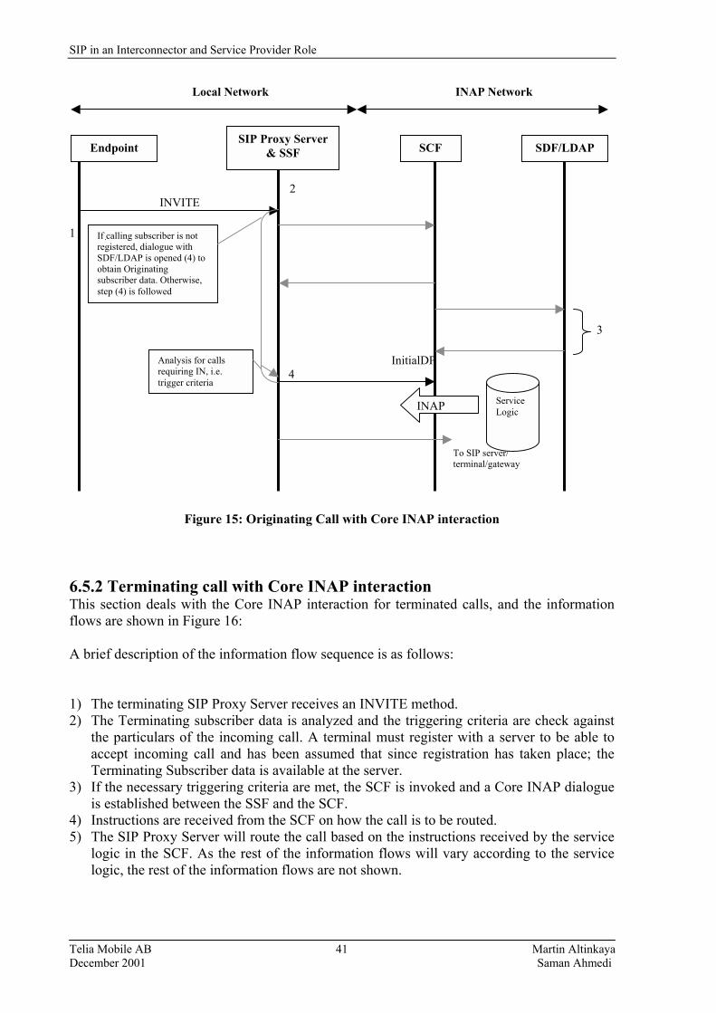
SIP in an Interconnector and Service Provider Role
Telia Mobile AB Martin Altinkaya December 2001 Saman Ahmedi
41
Local Network INAP Network 2 INVITE 1 3 InitialDP 4
To SIP server/ terminal/gateway
Figure 15: Originating Call with Core INAP interaction
6.5.2 Terminating call with Core INAP interaction This section deals with the Core INAP interaction for terminated calls, and the information flows are shown in Figure 16: A brief description of the information flow sequence is as follows: 1) The terminating SIP Proxy Server receives an INVITE method. 2) The Terminating subscriber data is analyzed and the triggering criteria are check against
the particulars of the incoming call. A terminal must register with a server to be able to accept incoming call and has been assumed that since registration has taken place; the Terminating Subscriber data is available at the server.
3) If the necessary triggering criteria are met, the SCF is invoked and a Core INAP dialogue is established between the SSF and the SCF.
4) Instructions are received from the SCF on how the call is to be routed. 5) The SIP Proxy Server will route the call based on the instructions received by the service
logic in the SCF. As the rest of the information flows will vary according to the service logic, the rest of the information flows are not shown.
Endpoint SIP Proxy Server
& SSF SCF SDF/LDAP
If calling subscriber is not registered, dialogue with SDF/LDAP is opened (4) to obtain Originating subscriber data. Otherwise, step (4) is followed
Analysis for calls requiring IN, i.e. trigger criteria
INAP Service Logic
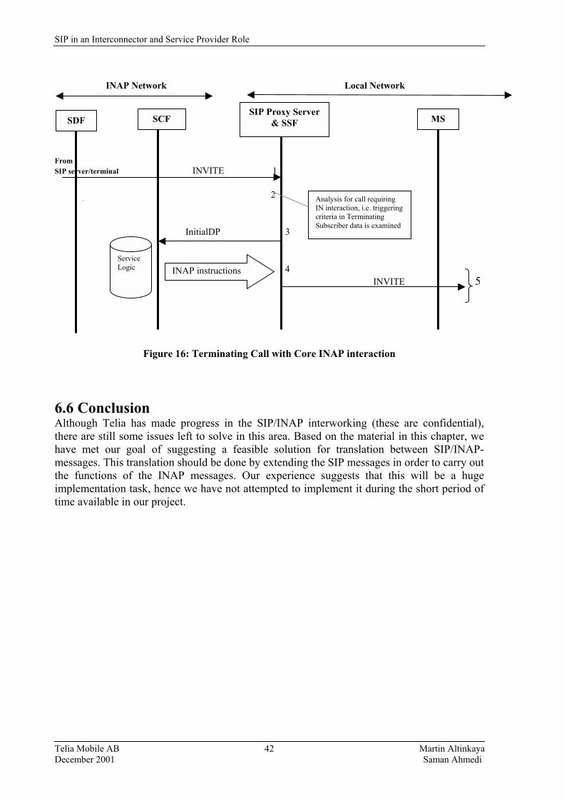
SIP in an Interconnector and Service Provider Role
Telia Mobile AB Martin Altinkaya December 2001 Saman Ahmedi
42
INAP Network Local Network From SIP server/terminal INVITE 1 2 InitialDP 3 4 INVITE 5
Figure 16: Terminating Call with Core INAP interaction
6.6 Conclusion Although Telia has made progress in the SIP/INAP interworking (these are confidential), there are still some issues left to solve in this area. Based on the material in this chapter, we have met our goal of suggesting a feasible solution for translation between SIP/INAP-messages. This translation should be done by extending the SIP messages in order to carry out the functions of the INAP messages. Our experience suggests that this will be a huge implementation task, hence we have not attempted to implement it during the short period of time available in our project.
SDF SIP Proxy Server
& SSF SCF MS
Analysis for call requiring IN interaction, i.e. triggering criteria in Terminating Subscriber data is examined
Service Logic INAP instructions

SIP in an Interconnector and Service Provider Role
Telia Mobile AB Martin Altinkaya December 2001 Saman Ahmedi
43
7. Quality of Service 7.1 Introduction It is expected that, in the future, end-to-end QoS mechanisms can be integrated in packet data networks. At this moment the traditional mobile telecommunication networks are moving towards packet data networks. Thus QoS architectures will be incorporated in the mobile telecommunication networks. It is therefore interesting to investigate how QoS can be metered, since this metered data can eventually be used as an input to an accounting process. This raises the question which data should be metered? Implementing QoS in current IP networks is a challenging task, as there is no real QoS features in the IPv4, even if there are some protocols like RSVP (section 7.4.1) and DiffServ (section 7.4.2), which one can use to ensure a certain QoS. IPv6 will have QoS features built in, but there are still some time away from a widely implementation it. When a user is registered under his HLR, the network can then offers the requested QoS (more on the HLR function can be found in section 8.3). The QoS provided must not exceed the QoS profile subscribed to by the user. If his request exceeds the profile subscribed for, then the user is not granted his request. The QoS profile granted by the network is known as the �negotiated� QoS. In this document a simple abstract view of QoS provisioning is used. The user selects a quality for a service based upon his own perception. This user selected QoS is translated into QoS attributes applicable to the specific QoS mechanism that actually accomplishes the required QoS. See the Figure 17: User Computer
Figure 17: User selects a given QoS, this is translated into attributes of the QoS mechanism The rest of this section is organized as follows. The next subsection describes the different network performance attributes. Later, QoS from a transport performance point of view is presented followed by the user sensitivity to performance related QoS. Section 7.4 describes the QoS classes for 3rd generation networks and section 7.5 gives an overview of different QoS proposals for service provisioning. 7.2 QoS Attributes Packet loss, Priority, Delay, Jitter and Throughput are typical measures of QoS.
Translation
QoS Mechanis

SIP in an Interconnector and Service Provider Role
Telia Mobile AB Martin Altinkaya December 2001 Saman Ahmedi
44
• Packet loss: This indicates the probability that packets are lost, duplicated or arrives out of sequencing. The number of lost packets is the number of packets sent to a specific receiver minus the number of received packets by that receiver.
• Priority: During network congestion, the packets to be discarded can be identified. There
are three levels of throughput, High, Normal and Low. Each of these are identified by a certain priority.
• Delay: The delay attribute specifies the maximum values of end-to-end delay. Delay is
the time it takes for a packet to go from the sender to the receiver. • Jitter: Indicates variations in the delay. It is the absolute value of the difference between
the arrival times of two neighbouring packets minus their departure times measured over many packets.
• Throughput: The number of packets or bytes transferred per unit time. 7.3 Transport performance related QoS From a business point of view, the subjective end-user perceived QoS is very important. End-users must be satisfied. End-user satisfaction depends on a lot of issues. Here, we focus on the issues that the network providers can influence with respect to the QoS. For type of application, a different kind of QoS may be required to satisfy the expectation of the end-user. For example, a videoconference requires at least a high throughput. Browsing photos though might require a high image resolution and a medium throughput would probably be sufficient in this case. In the following sections we will estimate QoS from a transport performance point of view. 7.3.1 QoS Mediation In this document we will use a simple model (Figure 18) to map the user selected QoS to the QoS mechanism that actually realizes this QoS in the network: User perceived QoS User selected QoS
Figure 18: Model of the QoS provisioning chain
In this model we assume that the users have their own perception of the QoS they would like to receive. It is also assumed in this model that the users have selected a QoS (that was offered by the network provider) based upon their perceived need and prior experience. This implies that the network provider or the application service provider should offer a set of QoS
QoS Mediation QoS
Mechanism
SIP in an Interconnector and Service Provider Role
Telia Mobile AB Martin Altinkaya December 2001 Saman Ahmedi
45
profiles that the user can chose from. For example, one can imagine a user requesting a streaming video service from a content server. The user is given the option of selecting an application and circumstance specific QoS from a set of QoS profiles. The user then explicitly requests their desired QoS before the content is streamed by the sender. Or the user already has subscribed to a specific QoS profile in which case it is already preselected. The selected QoS is translated into attributes applicable to the QoS mechanism that realizes the requested QoS. When the QoS mechanism has determined that it can provide the selected QoS, the sender can send the content to the user. The QoS Mediation entity translates the selected QoS of the user to a QoS request that can be interpreted by the Network Provider. The user�s terminal or the application service provider or network provider could carry out the translation. After the request has been translated it is to be realized by the QoS mechanism implemented in the network. The QoS mechanism in the network must actually provide the requested QoS, by carrying out its data transport network with implemented QoS mechanisms. The Network Provider receives the QoS request from the QoS Mediator and uses its QoS mechanisms to try and achieve the requested QoS. 7.3.2 User selected QoS The user perception of QoS depends on a number of issues. The user assesses image and sound quality on a subjective basis. Although it is unlikely that the user is capable of dividing its assessment in developed aspects an attempt is made here to name some of the aspects that contribute to the user�s overall assessment. However, for voice telephony there are measures of quality such as the Mean Opinion Score (MOS). With MOS, a wide range of listeners judge the quality of a voice sample on a scale of 1 (bad) to 5 (excellent). The scores are averaged to provide the MOS for that sample. Aspects within the assessment of performance related QoS include: • throughput • delay • distortion (due to jitter and loss) • reliability (e.g. percentage of the time that aforementioned aspects are above or below a
certain value) • Application. The application strongly influences the user�s perception of QoS. The user�s expectation of QoS (bandwidth, delay, distortion and reliability) varies per application category and terminal type. For example, the user do not whish delay in a videoconference. The required bandwidth can vary according to the requested resolution, distortion of the images, and the image refresh rate. 7.4 3rd Generation Application Categories Four QoS classes are defined for 3rd generation networks [26]. The main factor distinguishing these classes is how delay sensitive the traffic are. These classes are: • Conversational class: This class represents conversational streaming applications, e.g.
telephony speech or video conferencing that is very delay sensitive. This class is

SIP in an Interconnector and Service Provider Role
Telia Mobile AB Martin Altinkaya December 2001 Saman Ahmedi
46
characterized by low transfer delay, synchronization (i.e., preserving time relations between entities of the stream) and low delay variation.
• Streaming class: Most users do not have fast enough links to download large multimedia files quickly. With streaming, the client-browser can start displaying data before the entire file has been transmitted.
• Interactive class: Involves either a machine or human, on-line, requesting data from remote equipment (e.g. a server). Examples of human interaction with remote equipment are web browsing, database retrieval, server access, etc. examples of machines interaction with remote equipment are polling for measurement records and automatic database queries (telemetry). Its most important characteristic is that the content of the packets shall be preserved and transparently transferred with low bit error rate.
• Background class: This class represents the applications that are the most delay insensitive. The data that is processed by such an application can be processed in the background. Examples are background delivery of e-mail, SMS (Short Massage Services), and downloading of a database.
Due to the looser requirements of the Interactive and Background classes as opposed to Conversational and Streaming classes, the former can provide reduced error rates using techniques such as channel coding and retransmission. Traffic in the interactive class has higher priority than Background class traffic, so background applications use transmission resources only when interactive streaming and conventional applications do not need them. This is very important in wireless environment where the bandwidth is lower compared to fixed networks. Figure 19 summarizes the four described classes. Traffic class Conversational Streaming Interactive Background
Characteristics Preserve time relation between information entities Low delay
Preserve time relation between information entities
Preserve data integrity Request response pattern
Preserve data integrity Destination not expecting data within specific time
Example of application
Voice and Video-telephony
Streaming multimedia
Web browsing, Network games
Background download of e-mails
Figure 19: Summary of the 3G QoS classes 7.5 QoS Models for Service Provisioning In this section we describe the four QoS models, namely RSVP/IntServ, DiffServ, over-provisioning and Best-effort and Price-controlled Best-effort.
SIP in an Interconnector and Service Provider Role
Telia Mobile AB Martin Altinkaya December 2001 Saman Ahmedi
47
7.5.1 RSVP/IntServ This model [27] is composed of RSVP which represents a specific signaling protocol and service classes defined by the Integrated Services (IntServ) architecture [28, 29]. Its scope is to provide QoS for end-to-end services. The RSVP protocol introduces the concept of sessions which determine the unit time-scale of this model. The control loop of the RSVP/Intserv model tends to be network-centric in the sense of offering fairly advanced services inside the network among which applications may choose. A common argument against this QoS model is based on the resulting complexity for network elements. The most important tools to implement the RSVP/IntServ model are signaling and access control, however it also depends upon sensible network design and engineering in order to keep the blocking probability for a session low 7.5.2 DiffServ Differentiated Services provides a simple method of classifying services offered to various applications. Service classes are identified, packets are marked as belonging to a particular service and routers on the path examine headers do determine the treatment for the aggregate flow [8]. There are currently two standard Per-Hops Behaviors (PHBs) defined, these effectively produce two service levels: • Expedited Forwarding (EF): EF minimizes delay, jitters and provides the highest level
of aggregate quality of service. Any traffic that exceeds the traffic profile (which is defined by local policy) is discarded.
• Assured Forwarding (AF): Excess AF traffic is not delivered with as high probability as
indicated in the traffic profile, which means that it may be delayed, but not necessarily dropped.
DiffServ assumes the existence of a Service Level Agreement (SLA) between adjacent networks. The SLA establishes the policy criteria, and defines the traffic profile. It is expected that traffic will be policed and smoothed at outlet points according to the SLA, and any traffic above the upper bound at an ingress point, is not guaranteed to be forwarded. DiffServ�s simplicity with respect to priorizing traffic belies its flexibility and power. In contrast with RSVP, the amount of state information depends on the number of classes, not the number of flows. Classifications, authentication, marking, and shaping operations are only needed at boundaries and it is the sender who requests resources, not the receiver. 7.5.3 Over-provisioning and Best-effort This model argues for a continuation of the current operation of the Internet in a best-effort manner. The scope of this model is end-to-end in nature since all the intelligence is located in end-systems. Since there is no state in the network and all traffic is treated at the same granularity, it is as coarse-grained as possible. The time-scale of this model is very large and essentially equal to the length of one capacity planning cycle. Since end-systems are the only intelligent units in the network the control model is end-system-centric.

SIP in an Interconnector and Service Provider Role
Telia Mobile AB Martin Altinkaya December 2001 Saman Ahmedi
48
The most important tool applied by the model is that of network design/engineering in order to always-provision for super-abundance of network resources. However, in periods of scarity of resources this model relies on the adaptiveness of end-systems to address such situations. 7.5.4 Price-controlled Best-effort The authors of [30] think that over-provisioning alone is not sufficient without an additional means of signaling besides packet loss. This additional signaling is a per-packet price that may depend on the internal state of the network, e.g. its congestion level. This model is very similar to the pure over-provisioned best-effort model. However, its time-scale is related to the frequency of price announcements and due to the need to set prices, the network is not as passive as for an over-provisioning model. This model relies on the combination of network design/engineering and the adaptiveness of end-systems. It is also crucial for correct operation that the end-systems� or users� sensitivity to pricing signals can be estimated by the network operator who must adjust their pricing to achieve stable operation. These four proposals address different application requirements and, therefore, different business models. 7.6 Conclusion As there are a number of methods that have already been developed, we have not gone into the details of the mechanisms that they use, but have just an overview in order to select a suitable method to use. This selection will be described in section 8.8.

SIP in an Interconnector and Service Provider Role
Telia Mobile AB Martin Altinkaya December 2001 Saman Ahmedi
49
8. Charging and Payment Models 8.1 Introduction As the popularity of the Internet has grown, the number of services offered over the Internet has grown as well. Every carrier in the marketplace today is either considering, testing, or deploying IP-based services, including Telia.
ISPs are required to bill for any packet-based service including IP telephony, traditional packet data, voice, video, games, or any content transmitted over the network in packets. Service providers could price for their services based on: • The cost to the service provider; and • The value to the customer (Figure 20).
Figure 20: �Is the service worth its cost?�
Consumers today normally pay a flat monthly fee for unlimited access to join the Internet and are forced to accept service that is not guaranteed and has variable delays. However, as mentioned in the previous chapter, different applications have different service requirements, i.e. real-time data can not tolerate high delays, while services like email do. While the flat rate model offers simplicity and convenience both to the service providers and customers, the model is inflexible in distributing the cost-of-service among customers. As IP-based services increase in number and complexity, sticking with a flat rate billing model may mean trouble for service providers. The Internet and Mobile telephone communications (GSM, GPRS, UMTS, etc.) are converging. In order to provide improved infrastructure for these new services the network providers have the requirement to bill for the services they provide. Using the standard infrastructure of the Internet, today services become available on mobile telephone devices. Second and third generation GSM networks presented the network operators with many charging and billing challenges. GPRS may be charged for by packet usage counting, but the associated cost of measuring the packet usage may be greater than their income. The experience gained with charging for GPRS will be of value when UMTS is introduced in GSM networks.
service
service
service
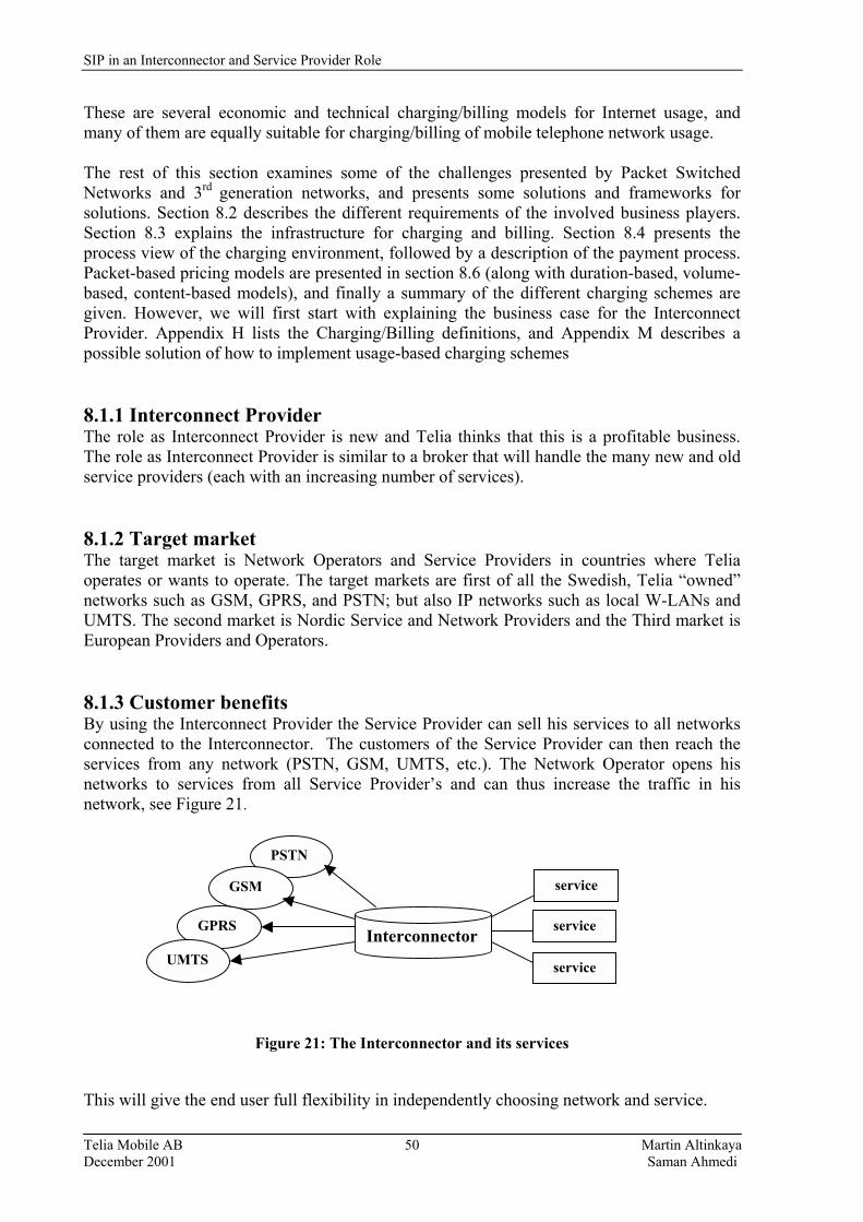
SIP in an Interconnector and Service Provider Role
Telia Mobile AB Martin Altinkaya December 2001 Saman Ahmedi
50
These are several economic and technical charging/billing models for Internet usage, and many of them are equally suitable for charging/billing of mobile telephone network usage. The rest of this section examines some of the challenges presented by Packet Switched Networks and 3rd generation networks, and presents some solutions and frameworks for solutions. Section 8.2 describes the different requirements of the involved business players. Section 8.3 explains the infrastructure for charging and billing. Section 8.4 presents the process view of the charging environment, followed by a description of the payment process. Packet-based pricing models are presented in section 8.6 (along with duration-based, volume-based, content-based models), and finally a summary of the different charging schemes are given. However, we will first start with explaining the business case for the Interconnect Provider. Appendix H lists the Charging/Billing definitions, and Appendix M describes a possible solution of how to implement usage-based charging schemes 8.1.1 Interconnect Provider The role as Interconnect Provider is new and Telia thinks that this is a profitable business. The role as Interconnect Provider is similar to a broker that will handle the many new and old service providers (each with an increasing number of services). 8.1.2 Target market The target market is Network Operators and Service Providers in countries where Telia operates or wants to operate. The target markets are first of all the Swedish, Telia �owned� networks such as GSM, GPRS, and PSTN; but also IP networks such as local W-LANs and UMTS. The second market is Nordic Service and Network Providers and the Third market is European Providers and Operators. 8.1.3 Customer benefits By using the Interconnect Provider the Service Provider can sell his services to all networks connected to the Interconnector. The customers of the Service Provider can then reach the services from any network (PSTN, GSM, UMTS, etc.). The Network Operator opens his networks to services from all Service Provider�s and can thus increase the traffic in his network, see Figure 21.
Figure 21: The Interconnector and its services
This will give the end user full flexibility in independently choosing network and service.
Interconnector
service
service
service
PSTN
GSM
GPRS
UMTS
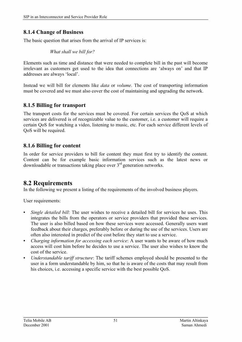
SIP in an Interconnector and Service Provider Role
Telia Mobile AB Martin Altinkaya December 2001 Saman Ahmedi
51
8.1.4 Change of Business The basic question that arises from the arrival of IP services is:
What shall we bill for? Elements such as time and distance that were needed to complete bill in the past will become irrelevant as customers get used to the idea that connections are �always on� and that IP addresses are always �local�. Instead we will bill for elements like data or volume. The cost of transporting information must be covered and we must also cover the cost of maintaining and upgrading the network.
8.1.5 Billing for transport The transport costs for the services must be covered. For certain services the QoS at which services are delivered is of recognizable value to the customer, i.e. a customer will require a certain QoS for watching a video, listening to music, etc. For each service different levels of QoS will be required. 8.1.6 Billing for content In order for service providers to bill for content they must first try to identify the content. Content can be for example basic information services such as the latest news or downloadable or transactions taking place over 3rd generation networks. 8.2 Requirements In the following we present a listing of the requirements of the involved business players. User requirements: • Single detailed bill: The user wishes to receive a detailed bill for services he uses. This
integrates the bills from the operators or service providers that provided these services. The user is also billed based on how these services were accessed. Generally users want feedback about their charges, preferably before or during the use of the services. Users are often also interested in predict of the cost before they start to use a service.
• Charging information for accessing each service: A user wants to be aware of how much access will cost him before he decides to use a service. The user also wishes to know the cost of the service.
• Understandable tariff structure: The tariff schemes employed should be presented to the user in a form understandable by him, so that he is aware of the costs that may result from his choices, i.e. accessing a specific service with the best possible QoS.
SIP in an Interconnector and Service Provider Role
Telia Mobile AB Martin Altinkaya December 2001 Saman Ahmedi
52
Operator requirements: • Integrated system for charging and billing: A secure charging and billing system residing
within the administrative domain of the operator. • Application of various charging models: As stated earlier, the operator charges for the
services he offers depending on several factors like volume of data transferred, the duration, the time of day, the user�s location, the service being accessed, and the QoS used to provide the service.
• Minimal load on the network: The charging and billing processes should not impose excessive load on the network.
• Flexibility. The tariffs and the charging models should be developed independently due to many business players influencing service charges.
• Fairness. Charges should fairly reflect network resources usage. • Real-time billing: The operator should be able to monitor whether the usage is within the
credit limit assigned to a particular user or not. This means that the billing process should be completed in real time.
Service provider requirements: • Modification of charging policies: The service provider should be able to modify the
pricing of its services. Since new types of services are constantly being introduced a major requirement is the ability to introduce new charging models.
• Competitiveness: Costs should be appropriate for the application. The cost of IP telephony usage should be equal or less than circuit switched telephony.
8.3 Infrastructure for charging and billing Network operators must first capture the network usage of all of the network�s users in order to charge for services. The network usage data then needs to be processed against the billing and charging models. The Mobile Switching Centers (MSC) in the Operational Network (ON) produces billing tickets for all the calls made in the mobile network. The billing tickets need to be collected and then processed so that the subscriber bills can be produced. Authentication of the subscribers is the HLR�s responsibility. The billing tickets are often collected by a mediation system. Mediation9 is the process of taking network element outputs and converting them into billable events. Refer to Appendix I for an overview on IP Mediation (this appendix also lists different Billing vendors).
A complication for GPRS charging is the overlap and convergence to the Internet and the multitude of diverse systems connected to it. With the already proposed Internet charging models the charging between the mobile and Internet networks providers has the potential to become very complicated and may include requirements for additional billing and charging systems in order to provide the required accounting. The addition of GPRS to the mobile network modifies the call flows for Internet packet data as shown in Figure 22 and includes the required gateway(s) to Internet services and external networks. 9 Source: IP Business Infrastructure - White Paper, The Insight Research Corporation, August 2000.
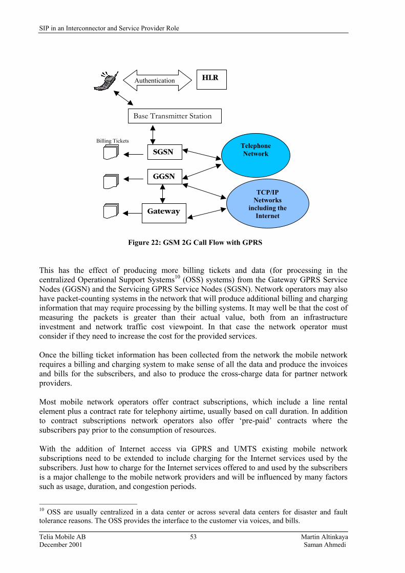
SIP in an Interconnector and Service Provider Role
Telia Mobile AB Martin Altinkaya December 2001 Saman Ahmedi
53
Billing Tickets Figure 22: GSM 2G Call Flow with GPRS This has the effect of producing more billing tickets and data (for processing in the centralized Operational Support Systems10 (OSS) systems) from the Gateway GPRS Service Nodes (GGSN) and the Servicing GPRS Service Nodes (SGSN). Network operators may also have packet-counting systems in the network that will produce additional billing and charging information that may require processing by the billing systems. It may well be that the cost of measuring the packets is greater than their actual value, both from an infrastructure investment and network traffic cost viewpoint. In that case the network operator must consider if they need to increase the cost for the provided services. Once the billing ticket information has been collected from the network the mobile network requires a billing and charging system to make sense of all the data and produce the invoices and bills for the subscribers, and also to produce the cross-charge data for partner network providers. Most mobile network operators offer contract subscriptions, which include a line rental element plus a contract rate for telephony airtime, usually based on call duration. In addition to contract subscriptions network operators also offer �pre-paid� contracts where the subscribers pay prior to the consumption of resources. With the addition of Internet access via GPRS and UMTS existing mobile network subscriptions need to be extended to include charging for the Internet services used by the subscribers. Just how to charge for the Internet services offered to and used by the subscribers is a major challenge to the mobile network providers and will be influenced by many factors such as usage, duration, and congestion periods.
10 OSS are usually centralized in a data center or across several data centers for disaster and fault tolerance reasons. The OSS provides the interface to the customer via voices, and bills.
Base Transmitter Station
SGSN
GGSN
Gateway
HLRAuthentication
Telephone Network
TCP/IP Networks
including the Internet

SIP in an Interconnector and Service Provider Role
Telia Mobile AB Martin Altinkaya December 2001 Saman Ahmedi
54
In most commercial environments some fraud is normally present. Mobile telephony networks are no exception. Fraud detection fits well into the billing and charging models and they often go hand in hand. An example of fraud in GSM networks is the running up of large bills on stolen mobile phones. This can be detected using the billing data and the mobile phone being used can be blocked in the network, but this incurs a high cost for real-time monitoring of the network traffic data along with the associated systems and personal costs. With the addition of GPRS and Internet services the opportunity for fraud increases and the network operators need to be aware of the different kinds of fraud that are possible and may occur. For example, the fear of users is that a provider may cheat or that other users may use their identity. Providers want to be sure that users will pay for the services used. 8.4 Process view of the charging environment Here we are explaining the customer process, the service provider process, the contract process, the charging process, and the resource use process which all are involved in the charging environment. We conclude in subsection 8.4.6 with a figure that relates the processes discussed. 8.4.1 Customer The customer process describes the general behavior of the customer, how they choose a service, an operator etc. Informal description: although the customer is the only actor in this process, their behavior is influenced by many factors, from service marketing by service providers to economic aspects. Activities within the customer process are invisible to other actors. The visible results of these activities are, for instance, service demand, the eventual choice of a particular service or service provider, and the actual use of a particular service. The customer�s service demands may be expressed as a source model that quantifies its communication needs. 8.4.2 Service Provider The service provider is modeled as a process containing all aspects related to its business as a service provider. It covers for example economic aspects and marketing aspects. Informal description: the service provider is the only actor in this process. As for economic aspects, the revenue from customers of a service must return the investment and maintenance costs for providing this service. The marketing aspects cover service definition, defining the contract interface to the customer, pricing, positioning and dimensioning its service in a possibly competitive market, etc. 8.4.3 Contract The contract defines the agreement between the customer and the service provider and addresses all issues necessary to allow an orderly use and provision of a service. Informal description: the contract may be a result of negotiation between the two actors. It is supposed to cover all aspects of service use as well as provision, e.g., includes type of service, QoS aspects (from a technical viewpoint), penalties for improper service provision, and also a description of how the customer will be charged for service use.

SIP in an Interconnector and Service Provider Role
Telia Mobile AB Martin Altinkaya December 2001 Saman Ahmedi
55
8.4.4 Charging The charging process embodies the determination of the charge associated with service use and provision. Informal description: the use of each service will be measured according to a number of parameters, such as duration of service use, time of the day, and the amount of information transferred (in case of a communication service). These parameters are agreed upon in the contract. 8.4.5 Resource Use The resource use process embodies the determination of the amount of each resource used as a result of service use. To this end, measurements, estimations, and calculations are performed to obtain values for parameters associated with resource use. Informal description: resource use determination is necessary to couple service use to the costs incurred. Resources may be of a physical nature, such as processing time, server access time, bandwidth use, but may also have a more abstract semantics, such as effective bandwidth, external resources, etc. A major difference between the resource use process and the charging process is that the former concerns use of resource, internal to the service and related to the implementation of the service, whereas the latter is customer oriented and related to the specification of the service.
8.4.6 Relation between the elements of the charging environment Figure 23 presents the relationship between the processes discussed above. A process is depicted as a node, and an edge between two nodes indicates a possible relation between the two nodes, and it also represents information flowing between them.
Figure 23: A process view of the charging environment.
Service Provider
Contract
Resource Use Charging
Customer
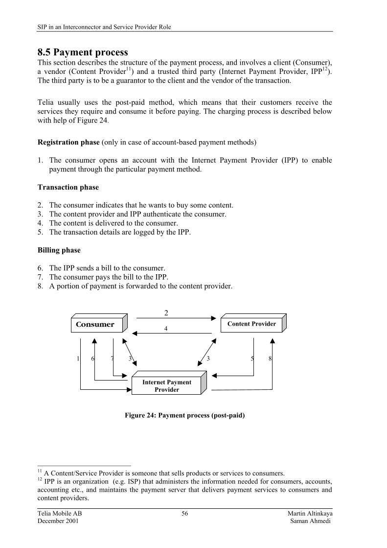
SIP in an Interconnector and Service Provider Role
Telia Mobile AB Martin Altinkaya December 2001 Saman Ahmedi
56
8.5 Payment process This section describes the structure of the payment process, and involves a client (Consumer), a vendor (Content Provider11) and a trusted third party (Internet Payment Provider, IPP12). The third party is to be a guarantor to the client and the vendor of the transaction.
Telia usually uses the post-paid method, which means that their customers receive the services they require and consume it before paying. The charging process is described below with help of Figure 24.
Registration phase (only in case of account-based payment methods) 1. The consumer opens an account with the Internet Payment Provider (IPP) to enable
payment through the particular payment method. Transaction phase 2. The consumer indicates that he wants to buy some content. 3. The content provider and IPP authenticate the consumer. 4. The content is delivered to the consumer. 5. The transaction details are logged by the IPP. Billing phase 6. The IPP sends a bill to the consumer. 7. The consumer pays the bill to the IPP. 8. A portion of payment is forwarded to the content provider. 2 4 1 6 7 3 3 5 8
Figure 24: Payment process (post-paid)
11 A Content/Service Provider is someone that sells products or services to consumers. 12 IPP is an organization (e.g. ISP) that administers the information needed for consumers, accounts, accounting etc., and maintains the payment server that delivers payment services to consumers and content providers.
Consumer Content Provider
Internet Payment Provider

SIP in an Interconnector and Service Provider Role
Telia Mobile AB Martin Altinkaya December 2001 Saman Ahmedi
57
8.6 Packet Based Charging Models The charging policy in telephone networks has existed for a long time and it works very well. However it has evolved over time. Figure 25 shows an example of a charging tree, specifying a possible charging scheme for a traditional telephony service.
Figure 25: Example of a charging tree Telephone companies offer a menu of local calling plans, some usage-based (e.g., metered service), some capacity based (e.g., unlimited service up to a defined capacity), and some a combination of both (e.g. a certain number of free minutes per month, plus a metered rate for calls in excess of this number). Similar charging policies are used in computer networks. Different mechanisms have different types of technical and economical advantages and disadvantages. As we already have mentioned, a user is charged for several components of his communication, (which are usually provided by several operators [31]).
User Server (Gateway) charges for access charges for IP based services charges for content charges for access charges for IP based services
Figure 26: Reference configuration and charges
Access Network
IP Network
Access Network
Phone
fixed periodic variable
Connection fee
Monthly subscription call
Call setup charge
call
Charge per minute

SIP in an Interconnector and Service Provider Role
Telia Mobile AB Martin Altinkaya December 2001 Saman Ahmedi
58
Figure 26 demonstrates how one operator can operate more than one of the networks shown. The server represents the usual service usage of the Internet. However, in case of Internet telephony the server could be a gateway to another network. The rest of this section gives an overview of various Packet Based Charging Models. Within some of these charging models, various pricing schemes exist. For example, priority pricing, market based pricing, and responsive pricing are all volume-based charging schemes (discussed in section 8.6.7), but they vary on the basis of QoS dependency, user perception, billing and accounting overheads, and network requirements. This section also compares the different charging models discussed, and ends with a summary. First, we will start by listing the evaluation criteria we use for comparing the charging models. 8.6.1 Evaluation Criteria Various evaluation criteria, for the various charging mechanisms will be used. These include • Compliance with existing technologies • Measurement requirements for billing and accounting • Support for congestion control or traffic management • Degree of network and economic efficiency. Compliance with existing technologies is an important indicator of implementation complexity. This criterion is stricter than an evaluation of the scheme�s implementation complexity in itself, as a scheme may be easily implemented, but non-compliant with existing technologies like ATM or IP, thus, precluding it from immediate deployment. Obviously, charging schemes that are compatible with existing technologies are easier to adapt than those requiring significant changes in the underlying network technology are. The amount of measurements required for billing and accounting is a related criterion indicating the implementation complexity of the pricing schemes. Some schemes require no measurements at all, thus simplifying accounting and billing considerably. Other schemes require extensive measurements. Support for congestion control or traffic management indicates the applicability of the pricing scheme for controlling network congestion by exploiting the price-sensitivity of users, thus inducing them to transmit less or shifting their use to during less congested periods. The degree of network efficiency evaluates the expected utilization levels in networks. While high utilization levels are desirable for the network operators, they are not necessarily desirable for the user. Low utilization levels imply availability of service. A highly utilized network, on the other hand, may have to deny service to some customers. 8.6.2 Criteria for Comparing Charging Schemes These criteria will be used to compare the charging models.
1. Usage Sensitivity: How sensitive is the charging model to the usage of network
resources? 2. Practicality: How easy and obvious is the implementation of the charging model?
SIP in an Interconnector and Service Provider Role
Telia Mobile AB Martin Altinkaya December 2001 Saman Ahmedi
59
3. Fairness to User: Users may appreciate a charging model if it is usage based. If a mean rate or some unfamiliar parameter have to be declared in advance, some users may end up paying for more bandwidth than they actually used. Alternatively, if an absolute maximum bandwidth is declared in advance then users pay only for time duration.
4. Fairness to Network Operator: Network operators may like a charging model which gives them the possibility of tuning prices for network resources according to demand.
5. Intelligence Required of User or Applications: How much does the user need to know about the workings of the charging model? How understandable to the user is the contract negotiation process; for example, does the user need to pre-declare detailed traffic statistics, the complexity of which may not his mathematical knowledge? How much experience does the user need in order to maximize his benefit when employing the particular charging model?
6. Predictability: Is the tariff known before a call? It may not be if it depends on some statistical properties of a source other than the simple mean and peak. Most users want a charging model that offers �no surprises�.
7. Expandability: Can the charging model be expanded, extended, or modified to accommodate the changing aspirations and requirements of users, customers, network operators, and service providers? Can all interested parties accept the changes in a way that is understandable and fair?
8. Robustness: How sensitive is the charging model to variations in the user�s traffic pattern?
9. Dynamic: To what extent, and how quickly, can the charging model adapt or respond, on-line, to changes in a user�s traffic?
10. Profitability to User and Operator: If a charging model is usage based, then employing it could potentially be profitable for customers and network operators alike. Knowledge of the nature of, and experience in using, a particular charging model could help customers and operators to maximize their respective gains when using the charging model.
11. Contract: Does the charging model implicitly or explicitly take account of the contract between customer and provider? This question is related to that of predictability.
8.6.3 Issues related to the charging models A charging model is split into two main parts [32]:
• Installation charge • Ongoing charges 8.6.3.1 Installation Charge The installation charge is related to the costs of providing access to the service. The price is a function of the �access part charging parameters�. Refer to Appendix J for access part charging parameters. The charging parameters are:
• Type of physical access • Maximum bandwidth allowed • Maximum number of simultaneous connections • Location of endpoints • Other (e.g. customer category, subscribed type of service).
SIP in an Interconnector and Service Provider Role
Telia Mobile AB Martin Altinkaya December 2001 Saman Ahmedi
60
8.6.3.2 Ongoing Charges There are two types of ongoing charges:
• Fixed charges • Variable usage charges 8.6.3.3 Fixed charges This is a fixed cost the customer pays independent of the level of their use, and may vary according to a number of parameters such as the availability of the service. The level of the charge depends on the network operator policy.
8.6.3.4 Variable Usage Charge The usage charge depends on the use of the service, and is associated with connections and traffic. A different value for the usage charge can be applied to each direction of the connection or traffic. A charging model should therefore be based on both directions.
The cost of usage of resolved resources is a function of the resources reserved by the network for this traffic, and is expressed:
Vc = KTR
Where:
Vc = variable cost K = constant T = duration R = Reserved resources
Duration The duration stands for the duration of the reservation. These reservations are for a continuous period of time, during which the service is not interrupted and the traffic contract is not modified. The traffic contract comprises the traffic parameters (for example bandwidth) and the QoS class.
The duration may be split up into phases, and each phase is associated with a particular set of traffic contract parameters. The price charged for traffic parameters depends on the time when the phase started. For example, it may be cheaper during nights. Constant The value Ki can be different for each phase, i.e. the formula is Vc = f(KiTiRi) where i stands for different phase during use of a service. Reserved resources The reserved resources are a function of the traffic contract and the admission control criteria associated with each of the operators involved. Each operator assigns based on the traffic contract and his normal resource allocation criteria.

SIP in an Interconnector and Service Provider Role
Telia Mobile AB Martin Altinkaya December 2001 Saman Ahmedi
61
8.6.4 Assigning usage to users A problem when considering accounting is how to allocate service usage to a particular user, without having to identify and authenticate the user for each separate request. Figure 27 shows a standard client-server situation.
Client Server servlet
http(s)
Web browser Web server
Figure 27: A client-server setting, with use of servlets Metering of resource usage can take place either at the client or the server. Metering at the server is often considered to be less open to �attacks�. However, metering at the server has the problem of identifying the client: how is request to the server linked to a particular client, and who is the user associated with that client at the time of the use of the server? There are several solutions to how to allocate usage to a particular user. We choose to describe three of them [33], with their advantages and disadvantages: Netscape HTTP cookies, IP addresses and the Common Gateway Interface (CGI) session driven approach. Cookies: Many web servers use Netscape cookies to associate state information with an interacting client application. When the client makes a request to the server, the server places a cookie on the client system, as shown in Figure 28.
Client Server
http(s) Metering
protocol & cookie Web browser Web server Accounting system
Figure 28: Resource usage metering and allocation using cookies The cookie is a small identifier that is sent by the client to the server which each subsequent HTTP request. Thus the web server can only keep track of the requests originating from the client system, and uses this to infer the behavior of the user. The advantages of cookies are:
SIP in an Interconnector and Service Provider Role
Telia Mobile AB Martin Altinkaya December 2001 Saman Ahmedi
62
• Each client has its own unique cookie that is a signature the server can use to store data. • Collisions between clients do not occur (i.e. data for client A does not get mixed with data
for client B). The disadvantages are: • Cookies can only be used with HTTP. • It�s browser-dependent and only functions for Netscape or Netscape-compatible clients. • The user�s web browser can be configured not to accept cookies. IP address: In an Internet environment, one of the simplest ways to identify the source of a request is to use an IP address. Once a user has been authenticated, the IP address from the authentication can be used to remember the identity of the user. The advantages of this solution are: • Easy to maintain, and does not consume system resources. • It is flexible and browser-independent. The disadvantages are: • Conflicts can arise, e.g., users behind a proxy or network address translator, or clients
using the same network interface. • Sensitive to fraud since there is nothing that prevents a host from putting any IP value into
the source address field. • Change of the IP-address each time the user logs in to the network (typical in many
operators access services). CGI session driven: The client contacts the server and receives a session ID that is passed from request to request. Calling each request with an CGI script preserves the ID. The advantages with this solution are: • Each client has its own unique session ID that is a signature the server can use to store
data. This insures that no collisions occur. • This solution is browser-independent. The disadvantages are: • The performance deteriorates, when accessing each page from a CGI script, especially if
there are many people accessing the pages. This overhead occurs each time each page is accessed because a CGI process is forked off, this consumes CPU resources.
• Sensitive to fraud, unless IDs expire quickly. 8.6.5 Duration Based Charging Many ISPs and European mobile and fixed line telephone companies are already using this charging model. The subscribers are charged for their connection to the service provider on a monthly basis and then charged for metered usage of access. This usage is usually measured in units of time and there is often a prepaid period of usage included with the monthly fee.

SIP in an Interconnector and Service Provider Role
Telia Mobile AB Martin Altinkaya December 2001 Saman Ahmedi
63
Within GPRS/UMTS, or any Packet-Switched based service, the duration of the call is not meaningful as a parameter of interest. GPRS permits the GSM network to be directly connected to LANs, WANs, and the Internet. A GPRS/UMTS user will be �always� logged on to the network, just as for IP-connections, but may or may not be actively using the network any given time. Therefore, duration-based billing does not fit well into the GPRS/UMTS Packet-Switched concept. Charging by the duration of connection time would encourage users to log off after sending data thereby stifling usage and increasing overhead, which is undesirable for both service providers and consumers. The duration of usage of specific applications, such as voice, may be of interest to the operator offering that application. For example, within a packet data protocol context lasting for 7 hours, a user may wish to make a voice call for a fraction of the time, say 10 minutes. If the operator wishes to charge the user for the voice call on a duration basis, record producing nodes within the GPRS/UMTS network need to be able to capture the duration of this application. This can be achieved in two ways, either by identifying the Access Point Name (APN)13 used or by using the Traffic Data Volume (TDV) counters in the SGSN and GGSN, if the same APN is used for several applications. Hence, if the user for example wishes to send e-mail he can connect himself to the network via APN 1, while he can use APN 2 for making the voice call. This is shown in Figure 29. APN 1 APN 2 1 a 1 b Activate PDP context connection path after Request Messages DNS resolution 2 a 2 b
User
Figure 29: Identification of the application If the same APN is used for several applications then the Call Detail Records (CDRs) produced at the SGSN and GGSN have parameters known as Traffic Data Volumes (TDV). A TDV contains several parameters such as the QoS profile. When a user who runs an e-mail application decides to run a voice application instead, the QoS profile will change in the TDV field. The operator records the point in time when these changes happen, and will use these to infer the duration of the applications (see Figure 30).
13 The network operator provisions the APNs for each subscriber in the HLR, when the subscriber contracts for the service. Types of access Points include Internet Service Providers, corporate networks, mail servers, games etc. Since these services differ from each other they will be charged differently.
GGSN
DNS Packet Data
Network
SGSN
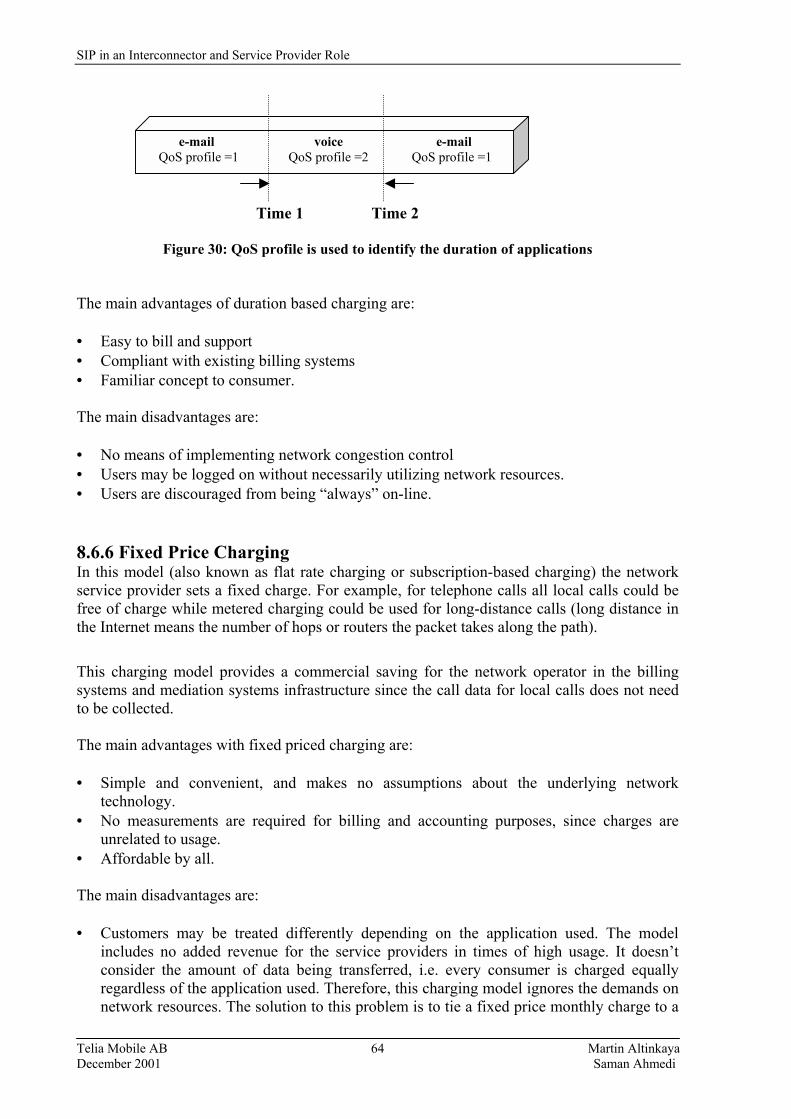
SIP in an Interconnector and Service Provider Role
Telia Mobile AB Martin Altinkaya December 2001 Saman Ahmedi
64
Time 1 Time 2
Figure 30: QoS profile is used to identify the duration of applications
The main advantages of duration based charging are: • Easy to bill and support • Compliant with existing billing systems • Familiar concept to consumer. The main disadvantages are: • No means of implementing network congestion control • Users may be logged on without necessarily utilizing network resources. • Users are discouraged from being �always� on-line.
8.6.6 Fixed Price Charging In this model (also known as flat rate charging or subscription-based charging) the network service provider sets a fixed charge. For example, for telephone calls all local calls could be free of charge while metered charging could be used for long-distance calls (long distance in the Internet means the number of hops or routers the packet takes along the path).
This charging model provides a commercial saving for the network operator in the billing systems and mediation systems infrastructure since the call data for local calls does not need to be collected. The main advantages with fixed priced charging are: • Simple and convenient, and makes no assumptions about the underlying network
technology. • No measurements are required for billing and accounting purposes, since charges are
unrelated to usage. • Affordable by all. The main disadvantages are: • Customers may be treated differently depending on the application used. The model
includes no added revenue for the service providers in times of high usage. It doesn�t consider the amount of data being transferred, i.e. every consumer is charged equally regardless of the application used. Therefore, this charging model ignores the demands on network resources. The solution to this problem is to tie a fixed price monthly charge to a
e-mail voice e-mail QoS profile =1 QoS profile =2 QoS profile =1
SIP in an Interconnector and Service Provider Role
Telia Mobile AB Martin Altinkaya December 2001 Saman Ahmedi
65
maximum megabyte allowance, and then charge the customer for each megabyte transferred over this limit. Subsection 8.6.8 describes this more in detail.
• There is no means of implementing network congestion control if no records are collected. Since fixed pricing fails to exchange the appropriate signals between users and network operators/service providers, it may lead to congestion and insufficient investment.
8.6.7 Volume Based Charging Volume based charging was invented because the functionality of �always� be on-line in packet switched networks result voids the idea of connection duration. Duration based charging doesn�t work in packet switched networks because network resources are used only when data is being transmitted/received.
In this charging model the users pay for the volume of the traffic they transfer. The model results in an increased number and complexity of CDRs as compared to the CDRs generated for circuit switched calls. For example such complexities are for: • Every Packet Data Protocol (PDP) context should be assigned a unique identity number
(CID) for billing purposes.
• Up-link and Downlink data volumes should be separately accounted for. The CDRs generated here need to include new parameters such as QoS, which doesn�t exist in the circuit switched domain. The advantages of volume based charging are:
• Ease of establishing profitable GPRS/UMTS business • Charges the customer for what they actually use • Easily resolves resource allocation and good for management of network bandwidth. The biggest argument against this scheme is that usage based charges change the user perception and may decrease user�s usage. Consumers are often unable to measure or predict their usage. The users may also find it hard to relate their use to data volume. For example they may not understand what 8 MB mean, or if they can download 10 audio files if they are limited to 5 MB.
The Volume based charging model has three subclasses, namely the Market based reservation pricing, Paris-Metro pricing, and Responsive pricing. These methods are described below. 8.6.7.1 Market Based Reservation Pricing In this model [34], also called smart�market pricing, the network subscribers place monetary bids that will influence the quality of service they receive from their network-based applications. The price of sending a packet varies minute-by-minute to reflect the current degree of network congestion. Each packet has a bid field in its header wherein the user indicates how much he is willing to pay. The network collects all bids and determines a threshold value and transmits all the packets whose bid exceeds the threshold value. The threshold value is determined by the network�s capacity and represents the marginal cost of congestion. Packets with higher bids will gain access to the network sooner than those with

SIP in an Interconnector and Service Provider Role
Telia Mobile AB Martin Altinkaya December 2001 Saman Ahmedi
66
lower bids, in the event of congestion. Each packet is then charged this marginal cost of congestion, and not the value of the bid. The market based charging model requires technical changes to protocols and networking hardware, which is an essential and significant cost. For each packet transmitted over the network the user�s billing records need to be updated. This scheme also doesn�t provide the users with service guarantees or a guarantee of reception. Another big problem associated with this scheme is that submitting a losing bid will typically lead to some unknown amount of delay (since the packet will be retransmitted at a later time). It may also allow some of the subscribers to gain unfair advantage when they have made high bid for certain services at the expense of other subscribers and network users. Despite these problems, market based pricing encourages both network and economic efficiency. During congestion, users will bid for access and routers will give priority to packets with the highest bid. A great deal of understanding by the operators will be required along the network for smooth functioning and to ensure that priority packets are not held up. For example, packets with high bids could be routed over shorter paths, whereas packets with low bits may be routed through longer paths. Another advantage with this scheme is that subscribers can influence their QoS from the mobile network by the value they attach to the service they require. The market based charging model will probably not be implemented as a charging mechanism due to its complexity and cost. However, it should be used after the use of some �traditional� models like duration based charging in order to make people use IP-telephony. 8.6.7.2 Paris-Metro Pricing Another way to deal with congestion in packet networks is provided by the Paris-Metro Charging model [35]. This model relies on providing differentiated levels of service based on customer usage pricing only. The subscribers assign a preferred priority level, an important QoS parameter, with an associated cost for their different network traffic. An end-user should be required to pay more to use a particular queue, although its architecture would be identical to a cheaper queue. The idea is that the queue that is more highly priced would attract less traffic and therefore suffer from less congestion than the queue with the lower price. This charging model gives flexibility to the network subscribers and also gives them control over the cost of their network traffic, since prices are a function of the relative importance of each packet. In the fixed price charging model (section 8.6.6), users are not faced with monetary incentives and thus will demand the highest priority for both loss and delay, while this scheme causes price sensitivity and thus, improves network performance. One disadvantage of this model is that it introduces mathematical complexity to the network�s behavior. The scheme requires extensive measurements for billing and accounting to keep track of the priority level of each transmitted packet for each user. Also individual QoS guarantees can�t be given to the customers. This charging model may work well in GPRS, UMTS, and IP-networks since it allows subscribers to prioritize network traffic, for example business emails may be considered more important that personal email so the cost penalty for higher priority may be considered appropriate for business email.
SIP in an Interconnector and Service Provider Role
Telia Mobile AB Martin Altinkaya December 2001 Saman Ahmedi
67
8.6.7.3 Responsive pricing Responsive pricing is very similar to the market-based pricing model, due to the fact that it only comes into operation during periods of congestion. Users are adaptive and respond to price signals. The network increases the price for network resources during high network utilization, and the adaptive users then reduce the traffic offered by themselves to the network. In case of low network utilization, the network decreases the price and the community of adaptive users could increase their offered traffic. In this way, adaptive users increase the network efficiency and economic efficiency. The disadvantages with this scheme are: • Increases network overhead, due to the network control nodes keeping track of the current
utilization level of the network, and thus the need to keep detailed billing and accounting records.
• An IN subsystem is required, to mediate the current tariff per packet to the user. • Instability, due to low network utilization it would reduce the prices, which will
encourage users to transmit, and thereby causing congestion. 8.6.8 Combination of Fixed-Price and Volume-based Volume-based charging is often used together with other charging models. Often it is used with fixed-price charging. The customers are charged a monthly fee depending on the QoS requested, and are allowed to transfer up to use a particular amount of data. Depending on the QoS profile the customers have subscribed for, they are classified as Gold, Silver, or Bronze. A particular QoS profile can be requested by a user on a per-service or per-session basis, and is stored in the HLR and is obtained by the SGSN. Every user is only granted the QoS profile he requested. Therefore, a Gold user wishing to be charged less for a particular session can request a lower QoS profile than he subscribed for, while a Bronze user can not request a higher QoS profile than he subscribed for. This can be implemented in the following way. Users belong to no particular class can request QoS on a per-session basis depending on the QoS they require on a particular session. Hence, the same user can request service with Gold QoS profile and request another service with Bronze QoS profile. All subscribers pay a set monthly subscription and are not differentiated and thus belong to no particular class. Subscribers are only charged for the volume of data they transfer and the QoS negotiated for these transfers. The QoS negotiated depends on the request by the user for a particular session. This gives the users freedom to choose a QoS profile on a per-session basis. This option requires more CDR recording and processing, but defines only three classes of QoS profile for ease and convenience. However, a network operator can choose to offer as many profiles as he wishes to with increasing discounts as the QoS steps down from high to low. However, the number of profiles possible is limited by standard definitions. The network operators may also limit this to suit their customer needs and reduce. The main advantages with the combination of fixed-price and volume-based charging are: • Allows flexibility and providing the possibility to maximize revenue • Charges the customer for what they actually use or what they prefer to be charged for • Management of network bandwidth is possibly • Easily incorporates QoS profile into charging The main disadvantage with this model is that it is strange to consumers who are used to paying for services by the minute.

SIP in an Interconnector and Service Provider Role
Telia Mobile AB Martin Altinkaya December 2001 Saman Ahmedi
68
8.6.9 Content value based Most of the charging models which charge users by data volume, duration, and subscription fail to reflect the value of the information, i.e., the content of the data packets. One user may find the content of a data packet important while another user may find it less important. Content value based charging takes advantaged of this to improve the revenue from the services. Metering will probably take place at the application level, and only units of content (rather than, e.g., packets) need to be counted. In the future it is very important for Network Operators to be able to identify the content of packets passing across their networks, and being delivered to their customers. The mediator�s ability to handle Internet Data Records (IPDRs) 14 [36] is very important for operators wishing to charge their customers for content, and identify applications in order to implement differential charging. Since most traffic will be inside the VPNs, network operators have no knowledge of the content, which complicates the implementation of this model. 3rd generation operators are concentrating on giving mobile users access to IP networks and IP-based services. Therefore, data records of IP data usage needs to be collected and combined with GPRS/UMTS usage data for transfer to the Billing System. These data records can not be produced at the SGSN or the GGSN. The GSNs are unable to capture and record the contents, and to identify the applications (i.e. whether it is voice, data or video) used by the data packets. Because of this, identifying where to collect the data from is one of the most important issues related to content billing. IPDR.org is working with this issue and is discussed briefly in Appendix K. The mediator is expected to be capable of processing the various CDRs of voice, video, and data usage coupled with IPDRs from other external IP network elements and providing a consolidated record for the operator�s legacy Billing Systems. The content provider can sell content to the operator or directly to the end-user. A common question for operators that are considering to using this charging method is whether consumers are interested in paying for content or not? If the content provider is to be charged, the network operator may have no mechanism for tracking the sender. On the other hand if the receiver is charged for the service, how do network operators control abuse of push services? More information on push services can be found in Appendix L. By introducing some kind of application alliance partner scheme, which only allows members of the Alliance partners to provide push services to end-users, may be a solution for network operators to track content/push service providers. Application providers register with the network operator and are provided with a code to enable the delivery of these push services. This is in accordance with the example scenario in Appendix L, whereby the network operator charges the content provider for the delivery of push services. Consumers are not charged, but rather the sender is charged. Advertising companies rely on the consumers to buy their product/service just as with any other form of advertisement. From these revenues the advertisers pay the network operator. Content value based billing requires, according to our evaluation criteria, additional nodes for handling of push services and advertisements. It also requires an extensive data collection facility from numerous network nodes and platforms.
14 IPDR is the IP equivalent of CDRs generated by telephone switches (MSC in GSM). Refer to Appendix K for more information on IPDR.
SIP in an Interconnector and Service Provider Role
Telia Mobile AB Martin Altinkaya December 2001 Saman Ahmedi
69
8.6.10 Packet charging This model is specific to Packet Switching [37] networks and involves counting the number of packets exchanged. This is a proposed method of metering Internet traffic and requires the implementation of packet counters in the network and complex billing systems that can process the packet data on a subscriber and customer basis. The advantage of per packet charging is that the absolute usage of the network and services can be metered, calculated, and billed for very accurately, as long as the packet information can be captured efficiently. The disadvantage of this model is that the cost of measuring the packets may be greater than their actual value, both from an infrastructure investment and additional network traffic viewpoint. 8.6.11 Capacity based Charging In capacity based charging [38], a subscriber would purchase a profile, called an expected capacity profile, based on his expected usage. The subscribers are charged for their expected average capacity and not the peak capacity of their access to the network. Charging involves using a filter at the user network interface to tag excess traffic; this traffic is then preferentially rejected by the network during network congestion, but is not charged for; but rather charges are determined by the filter parameters. Capacity based charging has the advantage of stable budgeting for network use. This model also gives the providers a more stable model of long-term capacity requirements and thus enables planning for dimensioning the network. This model fits well with mobile telephone networks and the administration of the agreed expected capacity would be done as part of the normal subscriber administration tasks. One disadvantage with this model is that the network operator has to police the actual capacity of the network used by subscribers and act accordingly by limiting the subscribers service to what has been purchased, or by invoicing the subscriber for the extra capacity used, on a metered tariff for example. 8.6.12 Edge Pricing This charging model [39] charges for the traffic where congestion costs are estimated using the expected congestion (e.g. time of day) along the expected path. Therefore, the resulting prices can be determined and charges are assessed locally at the access point (i.e. the edge of the provider�s network where the user�s packet enters), rather than computed in a distributed fashion along the entire path. One advantage of this model is that all pricing is done locally and does not involve exchanging billing data with other networks and partners for subscriber billing. Interconnection involves the network providers buying services from each other in same manner that regular users buy service (but probably at volume discounts). A disadvantage with this model is lack of clarity of routing via external networks and the costs of that traffic to both networks. The cost of collecting the edge usage information may exceed the value of the collected information.
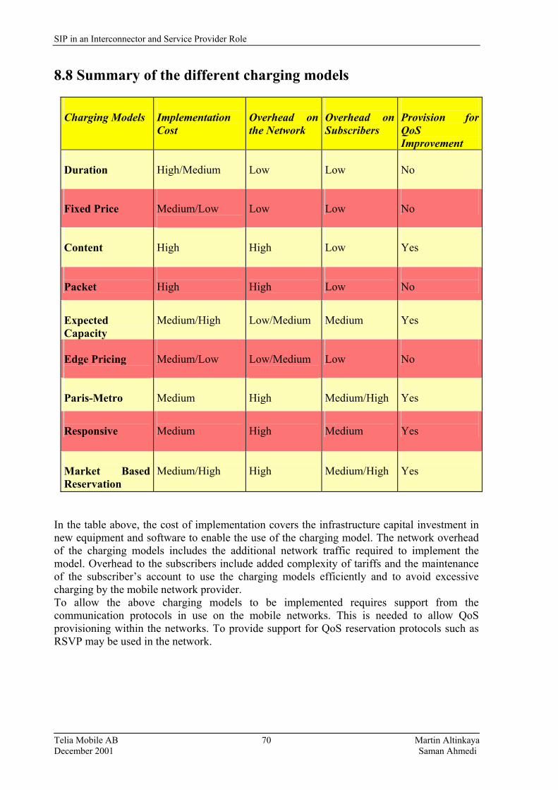
SIP in an Interconnector and Service Provider Role
Telia Mobile AB Martin Altinkaya December 2001 Saman Ahmedi
70
8.8 Summary of the different charging models
Charging Models
Implementation Cost
Overhead on the Network
Overhead on Subscribers
Provision for QoS Improvement
Duration
High/Medium
Low
Low
No
Fixed Price
Medium/Low
Low
Low
No
Content
High
High
Low
Yes
Packet
High
High
Low
No
Expected Capacity
Medium/High
Low/Medium
Medium
Yes
Edge Pricing
Medium/Low
Low/Medium
Low
No
Paris-Metro
Medium
High
Medium/High
Yes
Responsive
Medium
High
Medium
Yes
Market Based Reservation
Medium/High
High
Medium/High
Yes
In the table above, the cost of implementation covers the infrastructure capital investment in new equipment and software to enable the use of the charging model. The network overhead of the charging models includes the additional network traffic required to implement the model. Overhead to the subscribers include added complexity of tariffs and the maintenance of the subscriber�s account to use the charging models efficiently and to avoid excessive charging by the mobile network provider. To allow the above charging models to be implemented requires support from the communication protocols in use on the mobile networks. This is needed to allow QoS provisioning within the networks. To provide support for QoS reservation protocols such as RSVP may be used in the network.
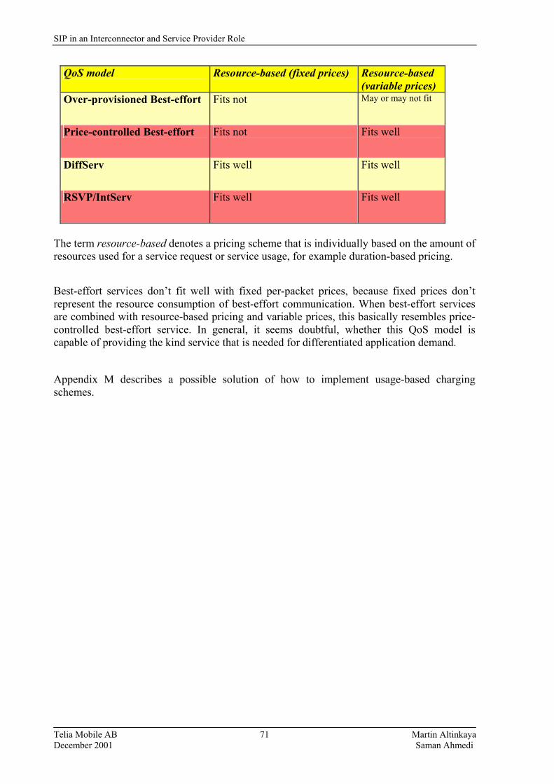
SIP in an Interconnector and Service Provider Role
Telia Mobile AB Martin Altinkaya December 2001 Saman Ahmedi
71
QoS model Resource-based (fixed prices) Resource-based (variable prices)
Over-provisioned Best-effort Fits not May or may not fit
Price-controlled Best-effort Fits not Fits well
DiffServ Fits well Fits well
RSVP/IntServ Fits well Fits well
The term resource-based denotes a pricing scheme that is individually based on the amount of resources used for a service request or service usage, for example duration-based pricing.
Best-effort services don�t fit well with fixed per-packet prices, because fixed prices don�t represent the resource consumption of best-effort communication. When best-effort services are combined with resource-based pricing and variable prices, this basically resembles price-controlled best-effort service. In general, it seems doubtful, whether this QoS model is capable of providing the kind service that is needed for differentiated application demand.
Appendix M describes a possible solution of how to implement usage-based charging schemes.
SIP in an Interconnector and Service Provider Role
Telia Mobile AB Martin Altinkaya December 2001 Saman Ahmedi
72
9. Conclusions During this master's thesis we have learned about the complexity of SS7 signaling and the IP-networks. Because there are such a large number of applications involved making these applications interoperate with each other will require a tremendous work. Fortunately some of the work is already done. In order to complete the rest of the work, people from both Telecommunication and Datacommunication need to work together in order to solve the remaining issues. Many working groups have been established and they are currently putting a lot of effort into solving the remaining problems required to interconnect IP-networks and Intelligent Networks. As we already have stressed, today there exist interconnections between VoIP and the PSTN (via gateways), but most of the services can not be used in both directions. Thus, the new services that are provided by SIP and VoIP can not be used via the PSTN telephony system, and the more traditional services that are available in the PSTN are not yet supported in conjunction with VoIP. There remain many problems to be solved. Fortunately, Telia AB is not the only operator or service provider that is interested in this business, in fact, almost all the traditional telecommunication operators are active in this area. As we concluded this report, we have realized that this report is as a drop of water to the ocean with regard to providing the needed connectivity between the different world of IP and SS7. The opinion of the so called "Netheads" (people with a datacommunication and Internet background) and the "Bellheads" (people with classical telecommunication background), are not the same, but if they could agree on the same platform, then progress would go faster. We believe that such a platform is emerging. Implementing ENUM is not a major task, but will provide a great service. Initially, a trusted third party (e.g. Telia or an equivalent company) should build a database that contains the necessary information regarding subscribers and the mapping of phone numbers to and from Internet addresses. Thus ENUM would replace the phone catalogue and number guidance ("Nummerupplysningen"); this will provide a service that will be appreciated by customers. As to QoS requests, there are several suitable models that can be used. We believe that best-effort QoS will be difficult to bill for, since people are used to receive much better quality when speaking via their phones. Today even cellular subscribers get better quality for their conversation than most VoIP users. However, as the adoption of broadband spreads, it should be less and less of a problem to ensure the required QoS. With the introduction of IP-telephony, one of the problems that arises is how to solve the remaining billing issues, as both operator and service providers want to make a profit for their part of the business. Based on the discussion in section 8, we think that a charging method that is based on duration will be most acceptable by customers, simply because of its fairness and simplicity. However, we believe that the method most operators and service providers would be interested in is the expected capacity charging model, since it supports QoS and the implementation costs are low. In conclusion we must say that not all services will be charged for using the same method. A specific mechanism could/should be used for specific services. The problems are how to implement all the different mechanisms, how to maintain them, and how to update them. The goals of this master's thesis were to propose possible solutions for the problems in the Golden Gate Architecture. The goals can be divided in four parts: SIP, SIP/ENUM

SIP in an Interconnector and Service Provider Role
Telia Mobile AB Martin Altinkaya December 2001 Saman Ahmedi
73
interworking, SIP/INAP interworking, and the Charging part. Three of these goals were met, but with respect to the translation of the messages between SIP and INAP, there is still a need for more work. We believe that neither we as students doing master of science thesis or Telia as an Operator/Service Provider, are prepared to dig deeply into the necessary coding of SIP/SS7 in order to extend them so as to support interoperability. One of the important insights we have gained is the importance of writing a draft detailing specific desires and send them to the relevant working groups, and the importance of keeping in touch with them as they try to solve the problems. In case of international standards like SIP and SS7, many (all) the involved participants need to be informed about new changes and extensions. We also learned that in order to make progress in an area that involves such a large number of protocols, one has to see the whole picture, and not just the small details in each protocol. It would be much easier if one could simply deal with a particular area of VoIP. Any one who is considering doing a work similar to ours, should start by collecting as much information as possible. This is especially important, as there are some sources that give misleading information about their progress and products. Thus we have not seen any company or equipment vendor that successfully bridges SIP and INAP services, despite the sources that claim that they have equipment that does this. When working in areas that are not discovered, you never have the right answers to the specific problems or issues that you are dealing with, so there are really no pattern that you can follow. It is an easy mistake to think that doing a work like this would be very simple. This was what we thought at the beginning, but later on we realized that it required much more efforts to collect information and to figure out how all these different protocols are related, and then write about them. Especially the INAP part was more difficult than we had expected, thus the translation between SIP/INAP is left undone. All that exist are different requirements from the operator/service providers on how INAP/SIP should interwork with each other. It is a major experience to go through a project like this, to be able to work at the edge of the technology, when the development is constantly updated. There are some things that we should do differently if we were to start this work all over again. For example, one important change would be to work closer to the hardware and software, thus examine and test the actual implementations, rather than just reading about them.
SIP in an Interconnector and Service Provider Role
Telia Mobile AB Martin Altinkaya December 2001 Saman Ahmedi
74
10. Future work As SIP is being updated continuously, one great desire is to provide all the IN services to IP networks. But unfortunately we are still some time away from this. A lot of work remains to be done regarding the translation between INAP- and SIP-messages. The difficulty involved with this has been discussed in detail throughout this report. A future task is to evaluate progress in this area, since it is still at the development phase. In case of Telia, they need to submit their needs and ideas via new Internet Drafts that carefully explain their requirements. In addition, agreements with other operators (in this area) need to be made, so that the interconnection between different networks works properly. A particular task for Telia following this thesis is to begin the implementation of ENUM-functions. Providing translation between telephone numbers and SIP-addresses will be a highly marketable service. In addition, we believe that this will be a simple task for Telia to accomplish. When deploying IP-telephony broadly a certain guarantee for the QoS has to be ensured so users will not be disappointed by their service. In addition, a suitable charging model has to be used. Further investigation of each of these models has to be done, in order to make sure that they are suitable over a longer term. Then it remains for Telia to choose a proper model to use and when to use it. During our project, the Golden Gate project was no longer on the agenda. Thus even though the prototype has been tested, there still remains some details to be addressed (such as enabling SIP to support IVR, as INAP does). This would be an interesting follow-up project to our work. Most of the focus of this report has been on definitions (SIP, SDP, etc.), this was necessary to lay out the map of the forest. Since in this paper we have given the basic facts and information about these protocols and the models, we believe that this can be directly used by further work as these protocols and models will probably remain fundamentally unchanged. The current version of the Golden Gate can not arm detection points in the circuit switched network in order to monitor the set-up phase of a call. Currently Golden Gate drops the call control once it has instructed the network what to do. The next phase of the Golden Gate project should find mechanisms to keep the control session alive throughout the call. However, the difficulty of working with SS7 signaling should not be underestimated because of its complexity. In this thesis we believe that we have laid a framework that can be used for further investigation for interconnect SS7/IN/SIP.
SIP in an Interconnector and Service Provider Role
Telia Mobile AB Martin Altinkaya December 2001 Saman Ahmedi
75
11. Abbreviations ADSL Asymmetric Digital Subscriber Line AF Assured Forwarding API Application Programming Interface APN Access Point Name ARPA Advanced research Projects Administration BGP Border Gateway Protocol CCF Call Control Function CDR Call Detail Record CGI Common Gateway Interface CS Capability Set CSN Circuit Switched Network DiffServ Differenteiated Services DNS Domain Name Server DP Detection Point DTMF Dual Tone Multi-Frequency EF Expedited Forwarding ENUM E.164 Number Mapping ETSI European Telecommunication Standard Institute FE Functional Entities FQDN Fully Qualified Domain Name GGSN Gateway GPRS Service Nodes GPRS General Packet Radio Service GSM Global System of Mobile Communication HLR Home Location Register HTML Hyper Text Markup Language HTTP Hyper Text Transfer Protocol ICP Interconnect Provider IETF Internet Engineering Task Force IN Intelligent Network INAP IN Application Protocol IntServ Integrated Services IP Internet Protocol IPDR Internet Detail Records IPP Internet Payment Provider ISDN Integrated Service Digital Networks ISO International Standards Organization ISP Internet Service Provider ISUP ISDN User Part ITAD Internet Telephony Administrative Domain ITU-T International Telecommunication Union IVR Interactive Voice Response LAN Local Area Network LDAP Lightweight Directory Protocol MAP Mobile Application Part MNP Mobile Number Portability MOS Mean Opinion score MSC Mobile Switching Center MTP Message Transfer Part
SIP in an Interconnector and Service Provider Role
Telia Mobile AB Martin Altinkaya December 2001 Saman Ahmedi
76
NAPT Network Address and Port Translation NAPTR Naming Authority Pointer Records ON Operational Network OSI Open System Interconnection OSS Operational Support Systems PBX Private Branch Exchange PC Personal Computer PDP Packet Data Protocol PHB Per-Hop Behavior PSTN Public Switched Telephony Network QoS Quality of Service RFC Request For Comment RSVP Resource Reservation Protocol RTCP Real-Time Control Protocol RTP Real-Time Protocol SCCP Signaling Connection Control Part SCF Service Control Function SC-G Session Control- Gateway SDF Service Data Function SDP Session Description Protocol SGSN Servicing GPRS Service Nodes SINAP Signaling INAP SIP Session Initiation Protocol SLA Sercvice Level Agreement SLP Service Logic Program SM Session Manager SMS Short Message Service SMTP Simple Mail Transfer Protocol SP Service Provider SPIRITS Service in the PSTN/IN Requesting InTernet Service SRF Specialized Resource Function SS7 Signaling System no.7 SSF Service Switching Function SSP Service Switching Points STP Signal Transfer Points TCAP Transaction Capabilities Application Part TCP Transmission Control Protocol TDM Time-Division Multiplexed TDV Traffic Data Volume TLD Top Level Domain TRIP Telephony Routing over IP TTL Time To Live UA User Agent UAC User Agent Client UAS User Agent Server UDP User Datagram Protocol UMTS Universal Mobile Telecommunication Systems URI Universal Resource Identifier URL Universal Resource Locator VBR Variable Bit Rate

SIP in an Interconnector and Service Provider Role
Telia Mobile AB Martin Altinkaya December 2001 Saman Ahmedi
77
VoIP Voice over IP VPN Virtual Private Network W-LAN Wireless LAN WAN Wide Area Networks WAP Wireless Application Protocol WWW World Wide Web
SIP in an Interconnector and Service Provider Role
Telia Mobile AB Martin Altinkaya December 2001 Saman Ahmedi
78
12. Table of Figures Figure 1: Overview of the Interconnector Role 7
Figure 2: The roles of the Interconnector and Service Provider 14
Figure 3: IP-Call between a PC and PSTN phone 17
Figure 4: SIP Communication flow 21
Figure 5: SIP-Call Set-up, similar to the three handshake in TCP 21
Figure 6: Typical INVITE message with SDP message body 23
Figure 7: Example of SDP header 25
Figure 8: Location or RTP and SIP in the IP stack 25
Figure 9: Input and output, to and from DNS Naming Authority Pointer (NAPTR) facilities. The FQDN is submitted, and a range of media-specific resource identifiers is 29 Figure 10: The �Golden Tree� 30
Figure 11: A DNS Query 31
Figure 12: INAP on top of the SS7 35
Figure 13: INAP on top of the IP-stack 36
Figure 14: A SIP based Call Control Configuration using SIP Proxy 38
Figure 15: Originating Call with Core INAP interaction 41
Figure 16: Terminating Call with Core INAP interaction 42
Figure 17: User selects a given QoS, this is translated into attributes of the QoS mechanism 43
Figure 18: Model of the QoS provisioning chain 44
Figure 19: Summary of the 3G classes 46
Figure 20: �Is the service worth the cost?� 49
Figure 21: The Interconnector and its services 50
Figure 22: GSM 2G Call flow with GPRS 53
Figure 23: A process view of the charging environment 55
Figure 24: Payment process (post-paid) 56
Figure 25: Example of a charging tree 57
Figure 26: Reference configuration and charges 57
Figure 27: A Client-Server setting, with use of servlets 61
Figure 28: Resource usage metering and allocation using cookies 61
Figure 29: Identification of the application 63
Figure 30: QoS profile is used to identify the duration of application 64
SIP in an Interconnector and Service Provider Role
Telia Mobile AB Martin Altinkaya December 2001 Saman Ahmedi
79
REFERENCES
[1] Sören Nyckelgårad and Stefan Hagbard, �Telia Golden Gate Technical Overview�, August 2000. http://www.telia.se/bvo/info/gen_info.jsp.html?OID=72285&CID=-24362,
[2] M. Handley, H. Schulzrinne, E. Schooler, and J. Rosenberg �SIP: Session Initiation Protocol�, RFC2543, March 1999. [3] M. Handley, and V. Jacobson
�SDP: Session Description Protocol�, RFC2327, April 1998. [4] H. Schulzrinne, S. Casner, R. Frederick, and V. Jacobson �RTP: Real-Time Transport Protocol�, RFC1889, January 1996. [5] P. Faltstrom �ENUM�, RFC2916, September 2000. [6] Richard W. Stevens, Chapter 14 in �TCP/IP Illustrated, Volume 1, The
Protocols.� Addison-Wesley,1999. [7] INAP (Intelligent Network Application Part):
http://www.hssworld.com/products/protocolstacks/inap/inap_home.htm, accessed on 12 August 2001.
[8] D.L. Black, S. Blake, M.A. Carlson, E. Davies, Z. Wang, and W. Weiss,
�An architecture for differentiated services�, RFC2475, December 1998. [9] R. Braden, L. Zhang, S. Berson, S. Herzog, and S. Jamin �RSVP�, RFC2205, September 1997. [10] Nortel Networks: http://www.nortelnetworks.com/index.html, accessed on 15th October
2001. [11] MAP (Mobile Application Part): http://www.protocols.com/pbook/ss7.htm, accessed
on 14th September 2001. [12] ISUP (ISDN User Part): http://www.intellinet-tech.com/products/isup.shtml, accessed on
5th October 2001. [13] TCAP (Transaction Capabilities Application Part):
http://www.protocols.com/pbook/ss7.htm, accessed on 15th of October 2001. [14] H.323: http://www.openh323.org/standards.html, created in1998. [15] VoIP-Server project, KTH/IT, by Martin Altinkaya, Mikael Sköldemar, Martin
Nygren, Ana Pena Garcia and Saman Ahmedi, May 2001. [16] Indigo Software: http://www.indigosw.com/products/indigo_products.shtml, accessed on
15th October 2001.

SIP in an Interconnector and Service Provider Role
Telia Mobile AB Martin Altinkaya December 2001 Saman Ahmedi
80
[17] Pingtel: http://www.pingtel.com, accessed on 13th September 2001. [18] 3Com: http://www.3com.com, accessed on 24th August 2001. [19] M. Mealling, and R. Daniel
�NAPTR (Naming Authority Pointer Records)�, RFC2915, September 2000 [20] Y. Rekhter, and T. Li
�BGP-4 (Border Gateway Protocol version 4)�, RFC1771, March 1995. [21] J. Moy
�OSPF (Open Shortest Path First)�, RFC2328 Version 2, April 1998 [22] Kevin McDermott
TRIP LS, Document Number: 00001. http://www.vovida.org/document/pdf/TripLsHLD.pdf
[23] L. Slutsman, I. Faynberg, H. Lu, and M. Weissman
�The SPIRITS Architecture�, RFC3136, 82001. [24] H. Lu, M. Krishnaswamy, L. Conroy, S. Bellovin, F. Burg, A., DeSimone, K.
Tewani, P. Davidson, H. Schulzrinne, K. Vishwanathan, �Toward the PSTN/Internet Inter-Networking--Pre-PINT Implementations�, RFC 2456, November 1998.
[25] Annex C � SINAP Product Description, Telia Mobile (Confidential). [26] Paulus Karremans, and Cor Willem Buizert, �Mapping of User Selected QoS to
RSVP and Diffserv Attributes�, Open REPORT, Ericsson, July 2001. http://ing.ctit.utwente.nl/WU5/D5.16/pa5.pdf
[27] R.Braden, D. Clark, and S. Shenker, �Integrated services in the Internet architecture�, RFC1633, June 1994.
[28] J.Wroclawski, �Specifications of the controlled-load network element service�
RFC2211, September 1997. [29] S. Shenker, C. Partridge and R. Guerin, �Specifications of guaranteed service�,
RFC2212, September 1997. [30] M. Karsten, J. Schmitt, B. Stiller, and L. Wolf, � Charging for packet-switched
network communication-motivation and overview�, White Paper, 2000. [31] N. Aloristioti, G. Evangelos, S. Panagiotakis, N. Houssos, M. Koutsopoulou,
N. Tsagkaris, P. Weingertner, F. Valero, S. Gessler, D. Vali, G. Agapiou, M. Schleger, C. Hoene, O. Fouial, N. Krallis, MOBIVAS platform for value-added services in mobile networks, �Requirements for general architecture & Interface specifications�, May 2000.
http://www.mobivas.cnl.di.uoa.gr/public/deliverables/dev212.pdf
SIP in an Interconnector and Service Provider Role
Telia Mobile AB Martin Altinkaya December 2001 Saman Ahmedi
81
[32] AC014: CANCAN (Contract Negotiation and Charging in ATM Networks), �ATM Charging Schemes�, Public Report, page 42-44, 1997.
http://www.elec.qmul.ac.uk/staffinfo/eric/cancan/312ds-b2.pdf [33] Internet Business Services, Inc, Electronic Commerce on the Internet http://www.geocities.com/SiliconValley/Garage/1236/WhitePaper/6-ecomm.html Accessed on 15th November 2001. [34] J. Mackie-Mason, and H. Varian �Pricing the Internet�, In Brian Kahin and
James Keller, editors, Public access to the Internet. Prentic-Hall, 1995. ftp://gopher.econ.1sa.umich.edu/pub/Ppapers/Pricing_the_Internet.ps.Z [35] A. Odluzko, �Paris Metro Pricing: The Minimalist Differentiated Services
Solution�, AT&T Laboratories Research, April 1999 [36] http://www.IPDR.org, Accessed on 15th November. [37] S. Keshav: �An Engineering Approach to Computer Networking�, Addison-
Wesley, 1997. [38] D. Clark, �A model for Cost Allocation and Pricing in the Internet�, MIT
Workshop on Internet Economics, March 1995. [39] S. Shenker, D. Clark, D. Estrin, S. Herzog. � Pricing in Computer Networks:
Reshaping the Research Agenda�, ACM Computer Communication Review. 26, 1996, pp. 19-43.
[40] AC014: CANCAN (Contract Negotiation and Charging in ATM Networks),
�ATM Charging Schemes�, Public Report, page 71-72, 1997. http://www.elec.qmul.ac.uk/staffinfo/eric/cancan/312ds-b2.pdf

SIP in an Interconnector and Service Provider Role
Telia Mobile AB Martin Altinkaya December 2001 Saman Ahmedi
82
Appendix A: SIP Definitions The following terms have special significance for SIP: Call: A call consists of all participants in a conference invited by a common source. A SIP call is identified by a globally unique call-id. Thus, if a user is, for example, invited to the same multicast session by several people, each of these invitations will be a unique call. A point-to-point Internet telephony conversation maps into a single SIP call. In a multiparty conference unit (MCU) based call-in conference, each participant uses a separate call to invite himself to the MCU. Call leg: A call leg is identified by the combination of the Call-ID header field and the addr-spec and tag of the To and From header fields. Within the same Call-ID, requests with From A and To value B belong to the same call leg as the requests in the opposite direction, i.e., From B and To A. Client: An application program that sends SIP requests. Clients may or may not interact directly with a human user. User agents and proxies contain clients (and servers). Conference: A multimedia session identified by a common session description. A conference can have zero or more members and includes the cases of a multicast conference, a full-mesh conference and a two-party telephone call, as well as combinations of these. Any number of calls can be used to create a conference. Downstream: Requests sent in the direction from the caller to the callee (i.e., user agent client to user agent server). Final response: A response that terminates a SIP transaction, as opposed to a provisional response that does not. The response has a response code and response message. The codes fall into classes 100 through 600, similar to HTTP. Unlike other requests, invitations cannot be answered immediately, as locating the callee and waiting for a human to answer may take several seconds. Call requests may also be queued, e.g., if the callee is busy. Responses of the 100 class (denoted as 1xx) indicate call progress; they are always followed by other responses indicating the final outcome of the request. While the 1xx responses are provisional, the other classes indicate the final status of the request: 2xx for success, 3xx for redirection, 4xx, 5xx and 6xx for client, server and global failures, respectively. Initiator, calling party, caller: The party initiating a session invitation. Note that the calling party does not have to be the same as the one creating the conference. Invitation: A request sent to a user (or service) requesting participation in a session. A successful SIP invitation consists of two transactions: an INVITE request followed by an ACK request. Invitee, invited user, called party, callee: The person or service that the calling party is trying to invite to a conference. Location service: A location service is used by a SIP redirect or proxy server to obtain information about a callee' s possible location(s). Examples of sources of location information include SIP registrars, databases or mobility registration protocols. Location services are
SIP in an Interconnector and Service Provider Role
Telia Mobile AB Martin Altinkaya December 2001 Saman Ahmedi
83
offered by location servers. Location servers may be part of a SIP server, but the manner in which a SIP server requests location services is beyond the scope of this document. Proxy, proxy server: An intermediary program that acts as both a server and a client for the purpose of making requests on behalf of other clients. Requests are serviced internally or by passing them on, possibly after translation, to other servers. A proxy interprets, and, if necessary, rewrites a request message before forwarding it. Proxy servers are, for example, used to route requests, enforce policies, and control firewalls. Redirect server: A redirect server is a server that accepts a SIP request, maps the address into zero or more new addresses and returns these addresses to the client. Unlike a proxy server, it does not initiate it's own SIP request. Unlike a user agent server, it does not accept calls. Registrar: A registrar is a server that accepts REGISTER requests. A registrar is typically co-located with a proxy or redirect server and may make its information available through the location server. Server: A server is an application program that accepts requests in order to service requests and sends back responses to those requests. Servers are proxy, redirect or user agent servers or registrars. Stateless Proxy: A logical entity that does not maintain state for a SIP transaction. A stateless proxy forwards every request it receives downstream and every response it receives upstream. Stateful Proxy: A logical entity that maintains state information at least for the duration of a SIP transaction. User agent client (UAC): A user agent client is a client application that initiates a SIP request. User agent server (UAS): A user agent server is a server application that contacts the user when a SIP request is received and that returns a response on behalf of the user. The response accepts, rejects or redirects the request. User agent (UA): An application, which can act both as a user agent client and user agent server. An application program may be capable of acting both as a client and a server. For example, a typical multimedia conference control application would act as a user agent client to initiate calls or to invite others to conferences and as a user agent server to accept invitations. The role of UAC and UAS as well as proxy and redirect servers are defined on a request-by-request basis. For example, the user agent initiating a call acts as a UAC when sending the initial INVITE request and as a UAS when receiving a BYE request from the callee. Similarly, the same software can act as a proxy server for one request and as a redirect server for the next request.

SIP in an Interconnector and Service Provider Role
Telia Mobile AB Martin Altinkaya December 2001 Saman Ahmedi
84
Appendix B: SIP Message Headers Message headers Every SIP message consists of several fields. The fields specifies among others things, the sender ID and the receiver's ID, the hops of the message flow from the sender to the receiver, the type of message and the length of the message. A SIP application doesn�t need to understand all the different types of headers, if an application doesn�t recognize the header of the message the application ignores it. In what order the headers arrive does not matter, but the Via fields and the "hop-by-hop" headers must arrive before the "end-to-end" headers. The "hop-by-hop" header changes by the servers between the clients, while the "end-to-end" headers don't changes between them. Via-Header: When a massage passes through a Proxy or is forwarded from a client, there is a risk that a message goes to an address where it has been earlier, i.e. loops. The Via-Header is used to avoid looping and has to be added to the message by all parties that have read the message. The proxy then has to check if the message has been there already. If this is the case the proxy has to respond with a reasonable response to indicate the detection of a loop. To-Header: A request and the response must contain a To-Header field, which indicate the desired recipient of the request. The User Agent Server (UAS) or redirect server copies the To-Header field into its response, adds a "tag" parameter. The tag parameter is used to distinguish responses from different sources with the same address, i.e. home phone and office phone. From-Header: The From-Header tells who initiated the request. This header contains a display name and the SIP-URL or just a SIP-URL. Contact: A contact field exists in both a request and response, this specifies where the user can be reached for further communication. Content-Type: This field specifies the kind of media the message contains. Call-ID: The Call-ID header fields uniquely identify a particular invitation or all registrations of a particular client. A multimedia conference can cause several invitations with different Call-ID. If a client is already member of a conference and receives a new invitation with unchanged parameters of the session, the client doesn't need to respond the invitation. CSeq: Every request must include a CSeq header field. CSeq header includes information about the request type. It also includes a single decimal unique sequence number chosen by the requesting client. Consecutive requests that differs in request method, header or body, but have the same Call-ID must contain strictly monotonically increasing and contiguous sequence numbers. Authorization: A user that wants to authenticate it self with a User Agent Server or registrar may do so by including an unauthorized request-header field with the request. The authorization field value consists of credentials containing the authentication information of the user agent for the realm resources being requested. The registrar or the UAS might also respond with a 401, Unauthorized, which forces the user to use an authorization header in the request.

SIP in an Interconnector and Service Provider Role
Telia Mobile AB Martin Altinkaya December 2001 Saman Ahmedi
85
Hide: A client uses a hide header to indicate that it wants the path comprised or the Via-Header fields to be hidden from a subsequent proxies and user agents. The field can take two forms, it can be either Hide: Hop or Hide: Route. If a request includes the "Hide: Hop" header field, the next proxy should hide previous via headers by encrypting them and then, unless it also wishes to remain anonymous, remove the hide header. If a request includes the "Hide: Route" header field all subsequent should hide their previous hop and the hide header should not be removed. Record-route: The record-route request and response header field is added to a request by any proxy that insists on being in the path of subsequent requests for the same call leg. It contains a globally reachable Request-URI that identifies the proxy server. Each proxy server adds its Request-URI to the beginning of the list. The server copies the Record-Route header field unchanged into the response. Proxy-Authenticate: The Proxy-Authenticate response-header field must be included as part of a 407 (Proxy Authentication Required) response. The field value consists of a challenge that indicates the authentication scheme and parameters applicable to the proxy for this Request-URI. Unlike its usage within HTTP, the Proxy-Authenticate header must be passed upstream in the response to the UAC. In SIP, only UAC's can authenticate themselves to proxies. Proxy-Authorization: The Proxy-Authorization request-header field allows the client to identify itself (or its user) to a proxy, which requires authentication. The Proxy-Authorization field value consists of credentials containing the authentication information of the user agent for the proxy and/or realm of the resource being requested. Unlike Authorization, the Proxy-Authorization header field applies only to the next outbound proxy that demanded authentication using the Proxy- Authenticate field. When multiple proxies are used in a chain, the Proxy-Authorization header field is consumed by the first outbound proxy that was expecting to receive credentials. A proxy may relay the credentials from the client request to the next proxy if that is the mechanism by which the proxies cooperatively authenticate a given request. WWW-Authenticate: The WWW-Authenticate response-header field must be included in 401 (Unauthorized) response messages. The field value consists of at least one challenge that indicates the authentication scheme(s) and parameters applicable to the Request-URI. A user agent should cache the authorization credentials for a given value of the destination (To header) and "realm" and attempt to reuse these values on the next request for that destination. Encryption: The encryption header is used to inform the recipient of the message that the message is encrypted, and what kind of algorithm and key has been used. Response-key: The Response-key header can be used by the sender to specify the key that the receiver should use to encrypt the response with. This allows the sender to use a temporary key or to contact users that don't know about his public key. Request: There exist six kinds of requests is SIP: INVITE, ACK, OPTION, BYE, CANCEL and REGISTER, see next section. They all represent methods in SIP and all are treated differently in SIP.

SIP in an Interconnector and Service Provider Role
Telia Mobile AB Martin Altinkaya December 2001 Saman Ahmedi
86
Appendix C: Response Status Code Definitions (RFC2543) Status Code Reason Phrase
100 Trying 180 Ringing 181 Call Is Being Forwarded 182 Queued 183 Session Progress 200 OK 300 Multiple Choice 301 Moved Permanently 302 Moved Temporarily 303 See Other 305 Use Proxy 380 Alternative Service 400 Bad Request 401 Unauthorized 402 Payment Required 403 Forbidden 404 Not Found 405 Method Not Allowed 406 Not Acceptable 407 Proxy Authentication Required 408 Request Timeout 409 Conflict 410 Gone 411 Length Required 413 Request Entity Too Long 414 Request-URI Too Long 415 Unsupported Media Type 420 Bad Extension 480 Temporarily Unavailable 481 Call Leg/Transaction Does Not Exist 482 Loop Detected 483 To Many Hops 484 Address Incompatible 485 Ambiguous 486 Busy Here 487 Request Terminated 488 Not Acceptable 500 Server Internal Error 501 Not Implemented 502 Bad Gateway
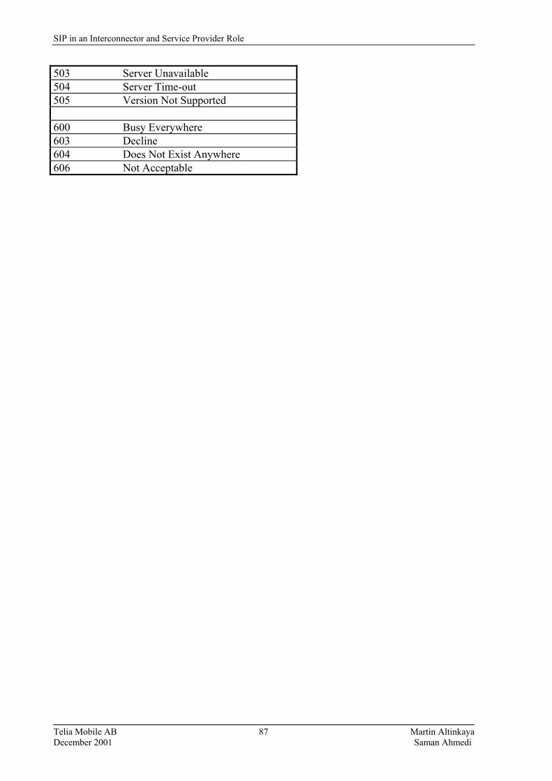
SIP in an Interconnector and Service Provider Role
Telia Mobile AB Martin Altinkaya December 2001 Saman Ahmedi
87
503 Server Unavailable 504 Server Time-out 505 Version Not Supported 600 Busy Everywhere 603 Decline 604 Does Not Exist Anywhere 606 Not Acceptable
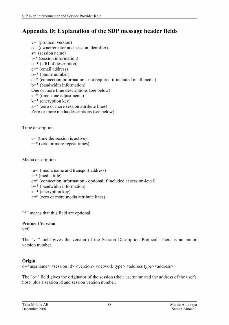
SIP in an Interconnector and Service Provider Role
Telia Mobile AB Martin Altinkaya December 2001 Saman Ahmedi
88
Appendix D: Explanation of the SDP message header fields v= (protocol version) o= (owner/creator and session identifier). s= (session name) i=* (session information) u=* (URI of description) e=* (email address) p=* (phone number) c=* (connection information - not required if included in all media) b=* (bandwidth information) One or more time descriptions (see below) z=* (time zone adjustments) k=* (encryption key) a=* (zero or more session attribute lines) Zero or more media descriptions (see below) Time description t= (time the session is active) r=* (zero or more repeat times) Media description m= (media name and transport address) i=* (media title) c=* (connection information - optional if included at session-level) b=* (bandwidth information) k=* (encryption key) a=* (zero or more media attribute lines) �*� means that this field are optional. Protocol Version v=0 The "v=" field gives the version of the Session Description Protocol. There is no minor version number. Origin o=<username> <session id> <version> <network type> <address type><address> The "o=" field gives the originator of the session (their username and the address of the user's host) plus a session id and session version number.
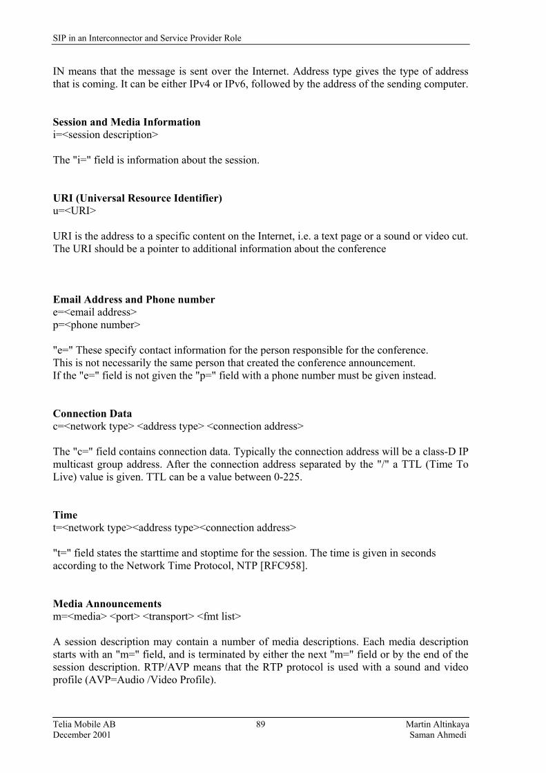
SIP in an Interconnector and Service Provider Role
Telia Mobile AB Martin Altinkaya December 2001 Saman Ahmedi
89
IN means that the message is sent over the Internet. Address type gives the type of address that is coming. It can be either IPv4 or IPv6, followed by the address of the sending computer. Session and Media Information i=<session description> The "i=" field is information about the session. URI (Universal Resource Identifier) u=<URI> URI is the address to a specific content on the Internet, i.e. a text page or a sound or video cut. The URI should be a pointer to additional information about the conference Email Address and Phone number e=<email address> p=<phone number> "e=" These specify contact information for the person responsible for the conference. This is not necessarily the same person that created the conference announcement. If the "e=" field is not given the "p=" field with a phone number must be given instead. Connection Data c=<network type> <address type> <connection address> The "c=" field contains connection data. Typically the connection address will be a class-D IP multicast group address. After the connection address separated by the "/" a TTL (Time To Live) value is given. TTL can be a value between 0-225. Time t=<network type><address type><connection address> "t=" field states the starttime and stoptime for the session. The time is given in seconds according to the Network Time Protocol, NTP [RFC958]. Media Announcements m=<media> <port> <transport> <fmt list> A session description may contain a number of media descriptions. Each media description starts with an "m=" field, and is terminated by either the next "m=" field or by the end of the session description. RTP/AVP means that the RTP protocol is used with a sound and video profile (AVP=Audio /Video Profile).
SIP in an Interconnector and Service Provider Role
Telia Mobile AB Martin Altinkaya December 2001 Saman Ahmedi
90
Appendix E: TRIP massages There are four different message types used by the TRIP protocol, OPEN, UPDATE, KEEPALIVE, and NOTIFICATION. OPEN Message This message contains the following mandatory fields: ! Version Itad TRIP Identifier ! Hold Time ! Optional Parameter Length There are other fields too; they are optional, for further description see TRIP LS [22]. UPDATE Message An Update Message is made up of a variable length sequence of routing attributes. The Update Messages represented by TRIPUpdateMsg calss. Each Attribute is made up of the following: ! Attribute Type ! Attribute Length ! Attribute Value For further information please refer to page 5 in [22]. KEEP ALIVE Message This message contains only the Message Header and is represented by the TRIPKeepAliveMsg calss. NOTIFICATION Message The Notification Message contains of the following: ! Error Code ! Error Subcode ! Error Data TRIP States The TRIPState is an abstract base calss which describes the current state of connection. ! Unknown Idle ! Connect ! Active ! OpenSent ! Open Confirm ! Establishment These states are described in details in [22], we will not go into to those states since it is not important for our report, just that TRIP is supported by SIP and H.323
SIP in an Interconnector and Service Provider Role
Telia Mobile AB Martin Altinkaya December 2001 Saman Ahmedi
91
Appendix F: TCAP messages Transaction Portion The transaction portion contains the package type identifier. There are seven package types: Unidirectional: Transfers component in one direction only. Query with Permission: Initiates a TCAP transaction. The destination node may end the transaction. Query without Permission: Initiates a TCAP transaction. The destination node may not end the transaction. Response: Ends the TCAP transaction. A response to an 1-800 query with permission may contain the routing number associated with the 800 number. Conversation with Permission: Continues a TCAP transaction. The destination node may end the transaction. Conversation without Permission: Continues a TCAP transaction. The destination node may not end the transaction. Abort: Terminates a transaction due to an abnormal situation. The transaction portion also contains the Originating Transaction ID and Responding Transaction ID fields which associate the TCAP transaction with a specific application at the originating and destination signaling points respectively. Component Portion The component portion contains components. There are six kinds of components: Invoke (Last): Invokes an operation. The component is the "last" component in the query. Invoke (Not Last): Similar to the Invoke (Last) component except that the component is followed by one or more components. Return Result (Last): Returns the result of an invoked operation. The component is the "last" component in the response. Return Result (Not Last): Similar to the Return Result (Last) component except that the component is followed by one or more components. Return Error: Reports the unsuccessful completion of an invoked operation. Reject: Indicates that an incorrect package type or component was received.
SIP in an Interconnector and Service Provider Role
Telia Mobile AB Martin Altinkaya December 2001 Saman Ahmedi
92
Appendix G: Interfaces required for SIP/IN interworking CCF-to CCF (IP) interface This interface reflects the requirement to carry an ISDN control plane signaling protocol for Multimedia services. This interface relays the IP Multimedia user plane received from the CCF (Call Control Function). This interface is required for VoIP based services. SCF-to SSF (IP) interface This interface reflects the requirement to carry an IN-based signaling protocol for IP and Multimedia services. This interface relays the IP Multimedia control plane triggered events to and from the SCF. This interface is required to trigger and control value-added services from a SIP Proxy/Redirect Server function in the IP- network, e.g. for multimedia access from the Internet �dial-up� access. CCF (IP)-to- Media Manager interface This interface reflects the requirement to carry an ISDN user plane protocol for Multimedia services. This interface relays the IP Multimedia user plane received from RTP and is defined as the Media Gateway Control interface. This interface is required for VoIP based services. Lower layer functional interfaces The following lower layer functional interfaces are to be considered and are described below followed by description of the different gateway functions: - IFa: SCF to SC-GF interface; - IFb: CCF to S-GF interface; - IFc: CCF to MM-GF interface; - IFd: SRF to MM-GF interface; - Ife: SC-GF to SSF interface; - IFf: S-GF to CCF CM interface; - IFg: MM-GF to CCF RM interface; IFa: SCF to SC-GF interface The Ifa interface will transport the SCF with service requests, to allow the SCF to instruct the collection of information necessary to execute the service (identity, charging and authenticity information) requests, and to control the gateway during service execution to the IP-network via the SC-GF. For example, for the Internet Call Waiting service, the SCF needs to notify the Internet user of an incoming call. Then, IFa should allow the SCF to request Internet services. This interface may require ITU-T standardization co-operatively between the IETF and the ITU-T, to reflect the requirements pertinent to the IFa reference point.

SIP in an Interconnector and Service Provider Role
Telia Mobile AB Martin Altinkaya December 2001 Saman Ahmedi
93
IFb: CCF to S-GF interface This is the requirement to carry an ISDN control plane signaling protocol for Multimedia services. This interface relays the IP Multimedia user plane received from the CCF. This interface is required for Voice over IP based services. IFc: CCF to MM-GF interface This interface reflects the requirement to carry an ISDN user plane protocol for Multimedia services. This interface relays the IP Multimedia user plane received from RTP/RTCP. This interface is required for Voice over IP-based services. This interface may require standardization but is not expected to be IN specific. IFd: SRF to MM-GF interface This interface will transport the SCF with service requests, to allow the SCF to instruct the collection of information necessary to execute the service (identity, charging and authenticity information) requests, and to control the gateway during service execution to the IP-network via the SC-GF. IFe: SC-GF to SSF interface This interface reflects the requirement to carry an IN-based signaling protocol for Multimedia services. This interface relays the IP Multimedia user plane. This interface is required to trigger and control value addeded services from a SIP proxy or H.323 gatekeeper function in the IP-network, e.g. for multimedia access from the Internet �dial-up access. IFf: S-GF to CCF CM interface This interface reflects the requirement to carry an IP control plane signaling protocol for Multimedia services. This interface relays the ISDN Multimedia user plane received from Ifc.
IFg: MM-GF to CCF-RM interface This interface reflects the requirement to carry an IP Media Gateway Control Protocol (e.g. H.248) for Multimedia services. This interface relays the ISDN Multimedia user plane received from IFe. This interface is required for Voice over IP-based services. This interface may require standardization but is not expected to be IN specific. The following lower layer protocol gateways may be required for the SIP/IN architecture:
SIP in an Interconnector and Service Provider Role
Telia Mobile AB Martin Altinkaya December 2001 Saman Ahmedi
94
Service Control Gateway Function (SC-GF) The Service Control Gateway Function (SC-GF) allows the interworking between the service control layer in Intelligent Network and IP-networks. Signaling Gateway Function (S-GF) The Signaling Gateway Function (S-GF) allows the interworking between the call control signaling in the CSN and IP-networks. This functional entity is optional, as it need not be required in all implementations. Media Manager Gateway Function (MM-GF) The Media Manager Gateway Function (MM-GF) is the functional entity within a gateway or MG, which is responsible for transforming CSN media (i.e. voice) to H.323 media (RTP/RTCP). The MM-GF supports the following functions:
- Interworking of VoIP calls with PSTN calls; - Service transcoding; e.g. for VoIP calls to PSTN telephony; - IP voice coding to PSTN voice coding conversion; - IP packet data to PSTN voice coding conversion; - IP packet data to PSTN/ISDN fax coding conversion.
SIP in an Interconnector and Service Provider Role
Telia Mobile AB Martin Altinkaya December 2001 Saman Ahmedi
95
Appendix H: Charging Definitions Accounting The process of collecting the information data for purposes of
attributing costs between service providers or network operators. Authentication Process of proving identity within a context. Authorization The process of granting permission (often based of identity), to
access or use a service, or to access information. Authorization is performed by the entity that controls the resource.
Bill The actual document received by the user within pre-defined time
intervals to inform about the charge. Billing The process of presenting the user with a request for payment e.g.
based on network usage; possibly including supporting information such as call records.
Charge The actual scheme that calculates the amount to charge the
customer for what the user has incurred for the use of a specific service.
Charging The process of determining the amount of money a user should
pay for using a certain service. Consumer Someone or some organization that uses the services supplied by
the content provider. Content provider Someone or some organization that sells products or services to
consumers over the Internet. Cost The financial price paid by a service provider or network operator
to provide and maintain a service to a user. This should be less than the charge to the customer in order to make a profit for the service provider or network operator.
Customer A customer pays for the user�s use of one or more services
provided by a service operator or by a network operator. Normally the customer is charged and billed for the above service use.
Customer Demand The demand of a customer for a specific service specifies the
expected use of this service. The customer uses this demand to make a selection among a number of alternative service providers, based on a comparison of expected charges. For each service provider, this charge is obtained by translating the demand in terms of values of the tariff parameters of the tariff statements of this service provider.

SIP in an Interconnector and Service Provider Role
Telia Mobile AB Martin Altinkaya December 2001 Saman Ahmedi
96
Identification An entity has identification within a specific context, and may therefore possesses multiple identities; one for each context in which it must be known. All identities within a particular context must be unique.
Interconnectivity A service that offers access between IP and ISDN/PSTN/GSM
networks. IPP (Internet Payment Provider) An organization that administrates the
information needed for consumers, accounts accounting etc. An IPP maintains the payment server that delivers payment services to consumers and content providers.
IP service provider A company or organization that provides access to IP services
which could be either access to a private IP network or to the Internet.
IP network provider A company or organization which provides access to an IP
network. IP telephony provider A provider who offers telephony services ver IP networks Price What the user expects to pay for the use of a certain service in a
certain way. It is the basis on which the decision of whether or not to use the service is based. The price is a an priori expectation.
Network Operator An organization that operates a telecommunication network. Profit The profit obtained by a service provider is the difference between
the charge levied on the customer for a service and the cost to the service provider in providing that service to the customer.
Service A service is a set of functions offered by organization A for
purchase by organization B in order to make a profit for organization A.
Subscriber A subscriber pays for the subscription to a service and for a
service; the service offers a more limited range of option to the user than a service for the use of which a customer pays.
Subscription A Subscription is the charge paid for obtaining access to a service;
normally this allows access on multiplicity of occasions over a nominal time duration.
Tariff A table or algorithm which uses set out how the charge will be
calculated given data from the connection.

SIP in an Interconnector and Service Provider Role
Telia Mobile AB Martin Altinkaya December 2001 Saman Ahmedi
97
Appendix I: IP Mediation Today, IP Billing Systems need to be much more customizable and segmented, they must be able to handle many more parameters, and these parameters vary widely according to service, must be reflected in the packet headers. In order to provide all these flexible and differentiated IP-services, information has to be gathered consistently and accurately. Mediation is the process of taking network element outputs and converting them into billable events.
IP Mediation is used to provide billing for IP services. It is not a billing system in its own right, but is an Interface to the IP network that is integrated into a billing system. Mediation is the process of taking switch and other network node outputs and converting them into billable event detail records. Mediation supplies the necessary �intelligent and billable� information to the Billing System, which in turn give Carriers access to Objected-Oriented Toolkits and open Application Programming Interfaces (APIs). This process allows Carriers to configure their own billing systems, giving them greater control over the programming and setting up of the network, since all the billing system functions are performed inhouse. A Billing System incorporates a variety of modules that interface with each other. Such modules can include Customer Relationship Management (CRM) and Fraud Detection Systems (FDS), as well as the billing engine, which self is a modular component of the system.
User SLA
Fraud Detection IP Billing Engine Customer Management System (FDS) relationship (CMR)
Figure 31: Visualization of the process.
Currently there are many IP-Mediation and IP Billing Systems vendors and only a very few offer a fully integrated turnkey solution. Although this is a niche area, it is important to remember that flexibility is one of the key issues, for these software systems to succeed, they must adapt and support the more established pre-existing billing systems that carriers have selected for their flat-rate Internet services.
Switch
API/Gateway
IP Mediation
SIP in an Interconnector and Service Provider Role
Telia Mobile AB Martin Altinkaya December 2001 Saman Ahmedi
98
This is where things start to get a little bit complicated, there are a large number of IP Billing vendors which supply dedicated ISP type of billing and there are the so-called IP Mediation Vendors. The major players in this sector works together in attempt to guarantee interoperability amongst participators and their solutions, since there is no industry-standard as yet. Billing System Vendors Success in providing Smart Billing is tightly connected with fully understanding the requirements and expectations. To ensure effective implementations, a very high level of technical and commercial dialogue is needed between the Carrier, Billing System Vendor, and as the Equipment Vendor(s). This ensures that the capabilities and expectations of each party are met. Some of the major companies reviewed include: XACCT (IP Mediation) http://www.xacct.com/scripts/search/query.htm Xacct Technologies develops business infrastructure software that enables service providers to design and execute flexible pricing models for differentiated value-added services and applications. The XACCTusage platform provides a single point of interface between back-office business and operations support systems and the physical network infrastructure, for usage data collection, automated user account provisioning, and pre-payment processing. Xacct does not provide specific billing solutions itself and, in order to widen its appeal, is designed to work as a plug-in solution with a variety of billing solutions, among those Portal, Amdocs, AMS, Convergys, Extent, Kenan Abor Billing. The XACCTready Alliance program is designed for three types of partners: Network Infrastructure Partners, Software Solution Partners, and Value Add Partners. Network Systems Partners are major players in the IP internetworking market. They include vendors of network infrastructure products, computing hardware, and software platforms. XACCT has performed interoperability testing with these partners' products to ensure they work seamlessly with XACCTusage.
NARUS INC./(IP Mediation/IP Billing/OSS) http://www.narus.com/solutions/mobileinternet.htm Narus is a provider of IP business infrastructure (IBI) systems. Narus's systems are based on the Semantic Traffic Analysis (STA) technology15, which captures customer usage data directly from carrier-grade networks and transforms it into actionable information. The foundation for all of NARUS's applications is the STA technology, which tries to identify all Internet applications. Both the Narus Billing Mediation System (BMS) 1.5, which captures 100% percent of usage-based network activity in real -time, and the Narus Intelligence Reporting System, which provides comprehensive reporting on customer usage, are based on STA technology. 15 http://www.atmdigest.com/archive/v6n103.txt, ATM News Digest, June 1999, volume 6, number 103.
SIP in an Interconnector and Service Provider Role
Telia Mobile AB Martin Altinkaya December 2001 Saman Ahmedi
99
KENAN SOLUTIONS (IP Billing/IP Billing/BSS/OSS) http://www.kenan.com Kenan, acquired by Lucent�s Software Products Group, develops and delivers software and services to address the requirements of service providers in the telecom and utility service industries worldwide, in areas including billing, customer care, order management, decision-support, usage mediation, network management, and operational support. Lucent's software products offer the following features and functionality: order entry, service provisioning, workflow management billing and rating, bill calculation and production, remittance processing, accounts receivable, collections, journals, customer care including account inquiry, adjustments and credits as well as customer and churn analysis, customer segmentation and campaign management. All of Lucent�s Software Products Group's solutions feature a scalable client/server architecture and are available on major UNIX platforms including Compaq®, HP, and Sun�; and supports Windows NT�; and HTML GUI clients. Lucent provides integration, training and maintenance services to support customer deployments. In addition, Lucent has forged global partnerships with systems integrators, hardware and database vendors, as well as value-added resellers and integration partners to extend its solutions capabilities as well as its reach to customers around the world. Their billing solution, Arbor/BP supposedly offers flexible, scalable billing, customer care, and customer analysis solution designed specifically for the needs of single- and multi-service communications and energy services providers. Arbor/BP provides comprehensive billing and customer care functions. PORTAL (IP Billing/OSS) http://www.portal.com Portal is building the business infrastructure for Internet services with Infranet, its real-time customer management and billing software designed for the Internet. Portal's Infranet allows companies to rate, track and analyze customer usage and billing in real time. Intranet�s modular architecture is designed to scale to support exponential growth. CONVERGYS (IP Billing/OSS) http://www.convergys.com/billing.html Convergys provides integrated billing and customer care services. Convergys enables companies leverage customer knowledge to achieve greater customer loyalty, reduce costs, drive innovation and increase revenue. The company provides and manages billing and customer support systems for companies worldwide in wireless, wireline, cable TV, cable telephony, direct broadcast satellite, Internet, utilities and converging communications markets. Also, Convergys provides outsourced, Web-enabled contact center systems to marketing-intensive companies in the communications, technology, financial services, consumer products and direct response marketing industries.

SIP in an Interconnector and Service Provider Role
Telia Mobile AB Martin Altinkaya December 2001 Saman Ahmedi
100
Appendix J: Access Part Charging Parameters The access part concerns the link from the Customer Equipment to the first element shared with other customers. The network operator or service provider is responsible for the maintenance of this link and devices. The network operator often places restrictions on the use of the physical link (e.g. to limit the use of bandwidth allowed to the customer). Both physical link and restrictions have an impact on the access part charging parameters to be considered. The charging parameters for the access part are as follows.
I. Type of physical access
• Description. This charging parameter refers to the possibility of having different types of physical access. Typical examples are copper links, monomode optical fiber links, and multimode optical fiber links.
• Entity responsible: This charging parameter will be directly managed by the operation system belonging to the network operator from whom the customer has requested the service. In fact, it corresponds to an agreement between user and network operator.
II. Length of the access (loop)
• Description: This parameter refers to the physical distance from the customer domain to the first network operator equipment shared with other customers.
• Entity responsible: The length of the access (loop) is a physical and measurable quantity. The network operator will communicate to the customer its value. Therefore, it is a parameter directly managed by the network operator�s network architecture.
III. Maximum bandwidth allowed
• Description: The maximum bandwidth allowed for the customer is physically limited by the capacity of the link, but may be artificially limited to a rate below this.
• Entity responsible: The negotiation is performed between customer and network
operator. The result of this negotiation has to be continuously verified.
IV. Maximum number of simultaneous connections
• Description: A maximum number of simultaneous virtual path connections or virtual channel connections will be supplied by the client at subscription time. This parameter, together with the previous one (maximum bandwidth allowed), will introduce a limit to the user related to the usage of the network resources. This limit will allow network operators to maintain the grade of service performance of their networks.
• Entity responsible: This parameter is agreed between client and network operator at subscription time. For the case of permanent/ reserved connections, the assignment of virtual path connections/virtual channel connections is controlled by the operation system. Therefore, the operation system will be the entity responsible of assuring the compliment of this limitation. On the other hand, the entity responsible for assuring
SIP in an Interconnector and Service Provider Role
Telia Mobile AB Martin Altinkaya December 2001 Saman Ahmedi
101
this limit will be the call control application, located within each virtual channel switch.
V. Others
• Some other charging parameters could be considered. Customer category, could be mentioned among them. This is a question of particular arrangements between customer and network operators. All of these parameters are negotiated at subscription time. In normal situations, this will imply a subscription fee. Obviously this subscription fee will be paid only one time (i.e. at subscription time).
SIP in an Interconnector and Service Provider Role
Telia Mobile AB Martin Altinkaya December 2001 Saman Ahmedi
102
Appendix K: Internet Protocol Data Record (IPDR) If a network operator wishes to charge content partners - banks, restaurants, cinemas, etc. based on a content, then the operator requires network nodes and devices capable of recording and collecting IP usage data. These IP-related data records are known as Internet Protocol Data Record (IPDR). A standard IPDR standard format is still under development by The Internet Protocol Detail Record Organization (IPDR.org). The Internet Protocol Detail Record Organization (IPDR.org) has taken the initiative to define the essential elements of data exchange between IP network elements, and Operational Support Systems (OSS)/Business Support Systems (BSS), i.e. to identify the information required to characterize an IP service (including e-commerce transactions) to the level of granularity desired by a BSS. The IPDR.org will also provide the foundation for development of open, carrier-grade IP support systems that enable next -generation IP networks to operate efficiently and cost effectively. IPDR.org specific goals include: • Define an open, flexible record format (the IPDR record) for exchanging usage
information. • Define essential parameters for any IP transaction. • Provide an extension mechanism, so network elements and support systems can exchange
optional usage metrics for a particular service. • Provide a repository for defined IPDRs. IPDR.org concluded that it was much better to develop the basic framework for the specification, allowing companies to develop working code against the framework, supporting interoperability and the usefulness of the specification. Following analysis of the results, the IPDR.org will identify additional elements for the specification that are more service-specific. This iterative approach will best meet the needs of the industry, and facilitate the achievement of IPDR�s goals according to IPDR.org. The IPDR.org Working Group is on the verge of approving and launching the IPDR compliant source code and has just announced the release for public comment of the organization�s first approved technical specification - Network Data Management - Usage (NDM-U) for IP-Based Services, version 1.0. The NDM function collects data from devices and service elements in a provider�s network. Usage refers to the type of data. IPDR.org has also extended their reach throughout the Telecommunications industry by building relationships with global associations, such as the GBA, to ensure that their work is aligned with the priorities of the entire industry. GBA�s next steps are to validate interoperability against the IPDR specification and address additional issues such as provisioning, record transport mechanisms, real-time APIs, security etc. The GBA is actively producing pricing and billing models to illustrate the scenarios where an operator might maximize revenues.
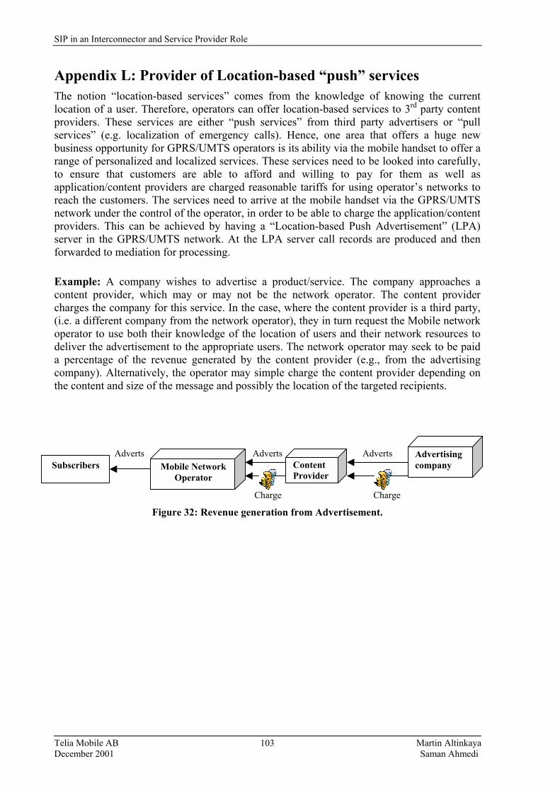
SIP in an Interconnector and Service Provider Role
Telia Mobile AB Martin Altinkaya December 2001 Saman Ahmedi
103
Appendix L: Provider of Location-based �push� services The notion �location-based services� comes from the knowledge of knowing the current location of a user. Therefore, operators can offer location-based services to 3rd party content providers. These services are either �push services� from third party advertisers or �pull services� (e.g. localization of emergency calls). Hence, one area that offers a huge new business opportunity for GPRS/UMTS operators is its ability via the mobile handset to offer a range of personalized and localized services. These services need to be looked into carefully, to ensure that customers are able to afford and willing to pay for them as well as application/content providers are charged reasonable tariffs for using operator�s networks to reach the customers. The services need to arrive at the mobile handset via the GPRS/UMTS network under the control of the operator, in order to be able to charge the application/content providers. This can be achieved by having a �Location-based Push Advertisement� (LPA) server in the GPRS/UMTS network. At the LPA server call records are produced and then forwarded to mediation for processing.
Example: A company wishes to advertise a product/service. The company approaches a content provider, which may or may not be the network operator. The content provider charges the company for this service. In the case, where the content provider is a third party, (i.e. a different company from the network operator), they in turn request the Mobile network operator to use both their knowledge of the location of users and their network resources to deliver the advertisement to the appropriate users. The network operator may seek to be paid a percentage of the revenue generated by the content provider (e.g., from the advertising company). Alternatively, the operator may simple charge the content provider depending on the content and size of the message and possibly the location of the targeted recipients.
Adverts Adverts Adverts
Charge Charge Figure 32: Revenue generation from Advertisement.
Content Provider
Advertising company Mobile Network
Operator Subscribers
SIP in an Interconnector and Service Provider Role
Telia Mobile AB Martin Altinkaya December 2001 Saman Ahmedi
104
Appendix M: Implementation of Usage Based Charging Schemes This appendix presents some preliminary ideas [40] about how to introduce the usage based charging schemes for real-time Variable Bit Rate (VBR) sources use of bandwidth. They are explained for some very simplified situations. The effective bandwidth itself could be considered as a possible basis for a charging scheme as it summarizes all statistical characteristics of the source into only one parameter. After this the source might be considered as a constant bit rate source with the mean rate equal to the effective bandwidth. So it could be charged as a constant bit rate source with a known mean rate. Unfortunately, the effective bandwidth concept has a number disadvantages. We mention here only those disadvantages that are related to the users: • it is too complicated to understand for most users what this concept means; • it is difficult to verify a charge for charging schemes based on the effective bandwidth; • the tariff table is unknown before the call, and • the tariff is expressed in terms which are not familiar to users. Below is a possible solution of how to introduce such a tariff, which will not have the above disadvantages, but will be still based on the effective bandwidth concept and will reflect the usage of resources. Suppose that a charge is calculated as follows: if the effective bandwidth of a call is E, then a user pays C* E amount of money per unit time, where C is some known coefficient. We want to introduce a charging scheme, which deals with mean rates instead of effective bandwidth, and it is equivalent to this one in a sense. The method is as follows: Suppose that during a sufficiently long time interval a network had N calls with mean bit rates m1 , . . ., mN , respectively. Denote duration of calls by T1 , . . . , TN , respectively. Suppose that the network has somehow estimated effective bandwidths of calls depending on the QoS requirements and has got the values E1 , . . . , EN . We are interested in estimation of �typical� ratio K = E/m for a call in the network, where m and E denotes the mean rate and the effective bandwidth of the call, respectively. In principle, there are a few ways to do this. A simple method is:
Ki = Ei / mi , i = 1, . . . , N . Then K can be estimated as
K = (T1 K1 + . . . + TN KN ) / (T1 + . . . + TN ). The value K can be used to relate the mean and the effective bandwidth of calls. This gives the possibility to express charging in a more familiar terms. A call with effective bandwidth E will be charged in the same way as a call with the mean rate m equal E/K. This means that if we know how to charge for calls with constant bit rate, then we will also have a procedure for charging of VBR calls and vice versa. So the network can charge users using only mean bit rate of the source. We note that in this case the total network revenue from users will be same as we would charge according to the effective bandwidth. On the other hand, users would pay about the same in both the cases. Some users would pay more in the first case than in the second and vice-versa. But it is important that if a user makes many calls during some time period, then his total payments to the network will converge to the same value. To be precise, the ratio of these payments will converge to 1. This statistical procedure is very simple. The estimation of K can be carried out in a few different ways. For this we need to estimate the
SIP in an Interconnector and Service Provider Role
Telia Mobile AB Martin Altinkaya December 2001 Saman Ahmedi
105
mean rate, the effective bandwidth and time duration of connections. There are the following possibilities to do this: • off-line estimation for �typical� recorded sources • selective on-line estimation for some sources • on-line estimation of all or almost all sources.