signal analysis pictail daughter board user's...
TRANSCRIPT

2004 Microchip Technology Inc. DS51476A
Signal Analysis
PICtail™ Daughter Board
User’s Guide

Note the following details of the code protection feature on Microchip devices:
• Microchip products meet the specification contained in their particular Microchip Data Sheet.
• Microchip believes that its family of products is one of the most secure families of its kind on the market today, when used in the
intended manner and under normal conditions.
• There are dishonest and possibly illegal methods used to breach the code protection feature. All of these methods, to our
knowledge, require using the Microchip products in a manner outside the operating specifications contained in Microchip’s Data
Sheets. Most likely, the person doing so is engaged in theft of intellectual property.
• Microchip is willing to work with the customer who is concerned about the integrity of their code.
• Neither Microchip nor any other semiconductor manufacturer can guarantee the security of their code. Code protection does not
mean that we are guaranteeing the product as “unbreakable.”
Code protection is constantly evolving. We at Microchip are committed to continuously improving the code protection features of our
products. Attempts to break Microchip’s code protection feature may be a violation of the Digital Millennium Copyright Act. If such acts
allow unauthorized access to your software or other copyrighted work, you may have a right to sue for relief under that Act.
Information contained in this publication regarding device
applications and the like is intended through suggestion only
and may be superseded by updates. It is your responsibility to
ensure that your application meets with your specifications.
No representation or warranty is given and no liability is
assumed by Microchip Technology Incorporated with respect
to the accuracy or use of such information, or infringement of
patents or other intellectual property rights arising from such
use or otherwise. Use of Microchip’s products as critical
components in life support systems is not authorized except
with express written approval by Microchip. No licenses are
conveyed, implicitly or otherwise, under any intellectual
property rights.
DS51476A-page ii
Trademarks
The Microchip name and logo, the Microchip logo, Accuron,
dsPIC, KEELOQ, microID, MPLAB, PIC, PICmicro, PICSTART,
PRO MATE, PowerSmart, rfPIC, and SmartShunt are
registered trademarks of Microchip Technology Incorporated
in the U.S.A. and other countries.
AmpLab, FilterLab, MXDEV, MXLAB, PICMASTER, SEEVAL,
SmartSensor and The Embedded Control Solutions Company
are registered trademarks of Microchip Technology
Incorporated in the U.S.A.
Analog-for-the-Digital Age, Application Maestro, dsPICDEM,
dsPICDEM.net, dsPICworks, ECAN, ECONOMONITOR,
FanSense, FlexROM, fuzzyLAB, In-Circuit Serial
Programming, ICSP, ICEPIC, Migratable Memory, MPASM,
MPLIB, MPLINK, MPSIM, PICkit, PICDEM, PICDEM.net,
PICLAB, PICtail, PowerCal, PowerInfo, PowerMate,
PowerTool, rfLAB, rfPICDEM, Select Mode, Smart Serial,
SmartTel and Total Endurance are trademarks of Microchip
Technology Incorporated in the U.S.A. and other countries.
SQTP is a service mark of Microchip Technology Incorporated
in the U.S.A.
All other trademarks mentioned herein are property of their
respective companies.
© 2004, Microchip Technology Incorporated, Printed in the
U.S.A., All Rights Reserved.
Printed on recycled paper.
2004 Microchip Technology Inc.
Microchip received ISO/TS-16949:2002 quality system certification for its worldwide headquarters, design and wafer fabrication facilities in Chandler and Tempe, Arizona and Mountain View, California in October 2003. The Company’s quality system processes and procedures are for its PICmicro® 8-bit MCUs, KEELOQ® code hopping devices, Serial EEPROMs, microperipherals, nonvolatile memory and analog products. In addition, Microchip’s quality system for the design and manufacture of development systems is ISO 9001:2000 certified.

SIGNAL ANALYSIS PICtail™
DAUGHTER BOARD USER’S GUIDE
Table of Contents
Preface ........................................................................................................................... 1
Chapter 1. Signal Analysis PICtail™ Daughter Board
1.1 Introduction ..................................................................................................... 7
1.2 Highlights ........................................................................................................ 7
1.3 Signal Analysis PICtail Daughter Board Kit Contents .................................... 7
1.4 Signal Analysis PICtail Daughter Board ......................................................... 7
1.5 PIC16F684 Firmware ................................................................................... 10
Chapter 2. Using the PICkit™ 1 Signal Analysis PC Application
2.1 Introduction ................................................................................................... 13
2.2 Highlights ...................................................................................................... 13
2.3 Programming PICA2Dlab Into The PIC16F684 ............................................ 13
2.4 Mode Selection ............................................................................................. 15
2.5 Oscilloscope Plot .......................................................................................... 17
2.6 FFT (Fast Fourier Transform) ....................................................................... 18
2.7 Histogram ..................................................................................................... 20
Chapter 3. Lesson Projects
3.1 Introduction ................................................................................................... 21
3.2 Highlights ...................................................................................................... 21
3.3 Lesson 1 – Thermistor .................................................................................. 21
3.4 Lesson 2 – Photodiode ................................................................................. 23
3.5 Lesson 3 – Pulse Width Modulated Generated Sine Wave ......................... 26
Chapter 4. Troubleshooting
4.1 Introduction ................................................................................................... 27
4.2 Common Problems ....................................................................................... 27
Appendix A. Hardware Schematics
A.1 Introduction .................................................................................................. 29
Worldwide Sales and Service .................................................................................... 30
2004 Microchip Technology Inc. DS51476A-page iii

Signal Analysis PICtail™ Daughter Board User’s Guide
NOTES:
DS51476A-page iv 2004 Microchip Technology Inc.
SIGNAL ANALYSIS PICtail™
DAUGHTER BOARD USER’S GUIDE
Preface
INTRODUCTION
This chapter contains general information about this user’s guide and customer support
that will be useful prior to using the Signal Analysis PICtail Daughter Board.
HIGHLIGHTS
Items discussed in this chapter are:
• About this Guide
• Warranty Registration
• Recommended Reading
• Troubleshooting
• The Microchip Web Site
• Development Systems Customer Notification Service
• Customer Support
ABOUT THIS GUIDE
This document describes how to use the Signal Analysis PICtail Daughter Board and
the PICkit™ 1 Signal Analysis PC Application using the PICkit 1 Flash Starter Kit. The
manual layout is as follows:
• Chapter 1: Signal Analysis PICtail Daughter Board – An overview of the Signal
Analysis PICtail Daughter Board. It describes the PCB layout, parts and electrical
connection to the PICkit 1 Flash Starter Kit.
• Chapter 2: Using the PICkit 1 Signal Analysis PC Application – This chapter
explains the operation of the PICkit 1 Signal Analysis PC Application.
• Chapter 3: Lesson Projects – Lessons that describe the different concepts in
controlling the signal analysis of the PIC microcontroller.
• Chapter 4: Troubleshooting – This chapter provides resolutions for solving com-
mon problems associated with using the Signal Analysis PICtail Daughter Board
and steps on how to resolve them.
• Appendix A: Hardware Schematics – Illustrates the Signal Analysis PICtail
Daughter Board hardware schematic diagrams.
2004 Microchip Technology Inc. DS51476A-page 1

Signal Analysis PICtail™ Daughter Board User’s Guide
Conventions Used in This Guide
This manual uses the following documentation conventions:
DOCUMENTATION CONVENTIONS
Documentation Updates
All documentation becomes dated, and this user’s guide is no exception. Since the
Signal Analysis PICtail Daughter Board User’s Guide and other Microchip tools are
constantly evolving to meet customer needs, some actual dialogs and/or tool
descriptions may differ from those in this document. Please refer to our web site to
obtain the latest documentation available.
Documentation Numbering Conventions
Documents are numbered with a “DS” number. The number is located on the bottom of
each page, in front of the page number. The numbering convention for the DS Number
is: DSXXXXXA, where:
Description Represents Examples
Code (Courier font):
Plain characters Sample code
Filenames and paths
#define STARTc:\autoexec.bat
Angle brackets: < > Variables <label>, <exp>
Square brackets [ ] Optional arguments MPASMWIN [main.asm]
Curly brackets and pipe
character: |
Choice of mutually exclusive argu-
ments; An OR selection
errorlevel 0|1
Lower case characters
in quotes
Type of data "filename"
Ellipses... Used to imply (but not show) addi-
tional text that is not relevant to the
example
list ["list_option..., "list_option"]
0xnnn A hexadecimal number where n is a
hexadecimal digit
0xFFFF, 0x007A
Italic characters A variable argument; it can be either a
type of data (in lower case characters)
or a specific example (in upper case
characters).
char isascii (char, ch);
Interface (Arial font):
Underlined, italic text
with right arrow
A menu selection from the menu bar File > Save
Bold characters A window or dialog button to click OK, Cancel
Characters in angle
brackets < >
A key on the keyboard <Tab>, <Ctrl-C>
Documents (Arial font):
Italic characters Referenced books MPLAB IDE User’s Guide
XXXXX = The document number.
A = The revision level of the document.
DS51476A-page 2 2004 Microchip Technology Inc.

Preface
WARRANTY REGISTRATION
Please complete the enclosed Warranty Registration Card and mail it promptly.
Sending in your Warranty Registration Card entitles you to receive new product
updates. Interim software releases are available at the Microchip web site.
RECOMMENDED READING
This user’s guide describes how to use the Signal Analysis PICtail Daughter Board and
the PICkit 1 Signal Analysis PC Application using the PICkit 1 Flash Starter Kit. Other
useful documents are listed below:
PICkit 1 Flash Starter Kit User’s Guide (DS40051)
Consult this document for instructions on how to use the PICkit 1 Flash Starter Kit
hardware and software. (This document can be found on the PICkit 1 Flash Starter Kit
CD-ROM (DS40049) included with the Signal Analysis PICtail Daughter Board Kit.)
PIC16C745/765 Data Sheet (DS41124)
Consult this document for information regarding the PIC16C745 8-pin based, 8-bit
CMOS Microcontroller with USB device specifications.
PIC16F684 Data Sheet (DS41202)
Consult this document for information regarding the PIC16F684 14-pin Flash based,
8-bit CMOS Microcontroller device specifications.
MPLAB IDE User’s Guide (DS51025)
Consult this document for more information pertaining to the installation and features
of the MPLAB Integrated Development Environment (IDE) Software.
MXLAB User’s Guide (DS51220)
Consult this document for more information regarding the Strip Chart, FFT and
Histogram functions. (This document is only available on the Microchip web site.)
Microchip Web Site
The Microchip web site (www.microchip.com) contains a wealth of documentation.
Individual data sheets, application notes, tutorials and user’s guides are all available
for easy download. All documentation is in Adobe® Acrobat® (pdf) format.
TROUBLESHOOTING
See Chapter 4 for information on common problems.
THE MICROCHIP WEB SITE
Microchip provides on-line support on the Microchip World Wide Web (WWW) site. The
web site is used by Microchip as a means to make files and information easily available
to customers. To view the site, you must have access to the Internet and a web
browser, such as, Netscape Navigator® or Microsoft® Internet Explorer.
The Microchip web site is available by using your favorite Internet browser to reach:
www.microchip.com
The web site provides a variety of services. Users may download files for the latest
development tools, data sheets, application notes, user’s guides, articles and sample
programs. A variety of information specific to the business of Microchip is also
available, including listings of Microchip sales offices, distributors and factory
representatives.
2004 Microchip Technology Inc. DS51476A-page 3

Signal Analysis PICtail™ Daughter Board User’s Guide
Technical Support
• Frequently Asked Questions (FAQ)
• On-line Discussion Groups – conferences for products, development systems,
technical information and more
• Microchip Consultant Program Member Listing
• Links to other useful web sites related to Microchip products
Engineer’s Toolbox
• Design Tips
• Device Errata
Other Available Information
• Latest Microchip Press Releases
• Listing of seminars and events
• Job Postings
DEVELOPMENT SYSTEMS CUSTOMER NOTIFICATION SERVICE
Microchip started the customer notification service to help our customers keep current
on Microchip products with the least amount of effort. Once you subscribe, you will
receive e-mail notification whenever we change, update, revise or have errata related
to your specified product family or development tool of interest.
Go to the Microchip web site at (www.microchip.com) and click on Customer Change
Notification. Follow the instructions to register.
The Development Systems product group categories are:
• Compilers
• Emulators
• In-Circuit Debuggers
• MPLAB IDE
• Programmers
Here is a description of these categories:
Compilers – The latest information on Microchip C compilers and other language
tools. These include the MPLAB C17, MPLAB C18 and MPLAB C30 C compilers;
MPASM™ and MPLAB ASM30 assemblers; MPLINK™ and MPLAB LINK30 object
linkers; MPLIB™ and MPLAB LIB30 object librarians.
Emulators – The latest information on Microchip in-circuit emulators. This includes the
MPLAB ICE 2000 and MPLAB ICE 4000.
In-Circuit Debuggers – The latest information on the Microchip in-circuit debugger,
MPLAB ICD 2.
MPLAB IDE – The latest information on Microchip MPLAB IDE, the Windows®
Integrated Development Environment for development systems tools. This list is
focused on the MPLAB IDE, MPLAB SIM and MPLAB SIM30 simulators, MPLAB IDE
Project Manager and general editing and debugging features.
Programmers – The latest information on Microchip device programmers. These
include the MPLAB PM3 and PRO MATE® II device programmers and PICSTART®
Plus development programmer.
DS51476A-page 4 2004 Microchip Technology Inc.

Preface
CUSTOMER SUPPORT
Users of Microchip products can receive assistance through several channels:
• Distributor or Representative
• Local Sales Office
• Field Application Engineer (FAE)
• Corporate Applications Engineer (CAE)
• Hotline
Customers should call their distributor, representative or field application engineer
(FAE) for support. Local sales offices are also available to help customers. See the
back cover for a list of sales offices and locations.
Corporate Applications Engineers (CAEs) may be contacted at (480) 792-7627.
In addition, there is a Systems Information and Upgrade Line. This line provides system
users a list of the latest versions of all of Microchip’s development systems software
products. Plus, this line provides information on how customers can receive any
currently available upgrade kits.
The Hotline Numbers are:
1-800-755-2345 for U.S. and most of Canada.
1-480-792-7302 for the rest of the world.
2004 Microchip Technology Inc. DS51476A-page 5

Signal Analysis PICtail™ Daughter Board User’s Guide
NOTES:
DS51476A-page 6 2004 Microchip Technology Inc.

SIGNAL ANALYSIS PICtail™
DAUGHTER BOARD USER’S GUIDE
Chapter 1. Signal Analysis PICtail™ Daughter Board
1.1 INTRODUCTION
This chapter introduces the Signal Analysis PICtail™ Daughter Board. It describes the
PCB layout, parts and electrical connection to the PICkit 1 Flash Starter Kit.
1.2 HIGHLIGHTS
This chapter discusses:
• The Signal Analysis PICtail Daughter Board Contents
• The Signal Analysis PICtail Daughter Board Hardware
• The Acquisition Firmware
1.3 SIGNAL ANALYSIS PICtail DAUGHTER BOARD KIT CONTENTS
The Signal Analysis PICtail Daughter Board Kit contains the following items:
1. The Signal Analysis PICtail Daughter Board Printed Circuit Board (PCB)
2. PICkit 1 Flash Starter Kit CD-ROM Version 2.0 (or later) (DS40049)
3. Pre-programmed PIC16C745 PICmicro® device with USB Version 2.0.0 (or later)
1.4 SIGNAL ANALYSIS PICtail DAUGHTER BOARD
The Signal Analysis PICtail Daughter Board works as an extension to the PICkit 1
Flash Starter Kit. When combined with PICkit 1 V2.0.0 (or later) firmware and the
PICkit 1 Signal Analysis PC Application, the Signal Analysis PICtail Daughter Board
can perform signal analysis capabilities such as:
• Real-time Strip Chart
• Oscilloscope
• Fast Fourier Transformation (FFT)
• Histogram
• Programming
2004 Microchip Technology Inc. DS51476A-page 7
Signal Analysis PICtail™ Daughter Board User’s Guide
1.4.1 PCB Layout and Parts
Figure 1-1 shows the PCB layout of the Signal Analysis board. It is populated with a
PIC16F684 and two 25LC640 serial EEPROM memory devices. The PIC16F684 I/O
pins RC0, RC1 and RC3 are connected directly to test point connections on the edge
of the PCB. These can be configured as comparator analog inputs (RC0/AN4,
RC1/AN5), analog-to-digital converter inputs (RC0/AN4, RC1/AN5, RC3/AN7) or as
digital input/output pins. I/O pin RC5 is connected through a RC filter (R1 and C4) to a
test point connection. RC5 is the P1A output of the Enhanced Capture/Compare/Pulse
Width Modulation (ECCP) module. It can be configured for digital PWM output.
Additionally, +5V and ground test points are available as test point connections.
Two 25LC640 SPI™ compatible serial EEPROM memory devices provide 8-bit by 16K
bytes of non-volatile memory. They are used in conjunction with the signal analysis
firmware (PICA2Dlab.hex) program to store data at a specified sample rate. For non
real-time acquisition modes (oscilloscope, FFT and histogram), the PC program
downloads the data from the 25LC640’s for computation and display.
Connector J1 allows additional circuit boards (for example temperature, light or
pressure sensors) to be plugged into the Signal Analysis board for signal measurement
and analysis. All port pins from the PIC16F684 are available on the J1 connector.
FIGURE 1-1: SIGNAL ANALYSIS PICtail™ DAUGHTER BOARD
GND
+5V
PICtail™ Daughter Board
Signal Analysis
RC5
RC0
RC1
RC3
C1
U1
U3
C3
C2
U2
R1C4
J1
P1
RA5
RA4
RA3
RC5
RC4
RC3
RC0
RA1
RA2
RC0
RC1
RC2
+5V
GND
DS51476A-page 8 2004 Microchip Technology Inc.

Signal Analysis PICtail™ Daughter Board
1.4.2 Electrical Connections
Figure 1-2 shows how the Signal Analysis PICtail Daughter Board plugs into the
PICkit 1 Flash Starter Kit expansion header J3. The Signal Analysis Board electrically
detaches the PICkit 1 onboard LED array. The target PICmicro device is plugged into
the Signal Analysis Board DIP socket U1. Remove any PICmicro devices from the
Evaluation Socket on the PICkit 1 Flash Starter Kit.
FIGURE 1-2: SIGNAL ANALYSIS PICtail™ DAUGHTER BOARD
ORIENTATION
Figure 1-3 shows the electrical connections of the Signal Analysis PICtail Daughter
Board with the PICkit 1 Flash Starter Kit. There are five connections: +5V, Ground,
ICSPCLK, ICSPDAT and VPP (see Figure A-1 in Appendix A. “Hardware
Schematics”). These signals allow the target PICmicro device, plugged into U1 DIP
socket on the Signal Analysis PICtail Daughter Board, to be programmed and provide
bidirectional synchronous serial communications with the PICkit 1 PIC16C745 micro-
controller with USB device. With PICkit 1 V2.0.0 (or later) firmware, the user can
communicate to and from the target PICmicro device via USB serial communications.
This facilitates PC host programs to command, control and communicate with the
target PICmicro device that is being evaluated or for program development.
Note: When the Signal Analysis PICtail Daughter Board is plugged into the
PICkit 1 Flash Starter Kit, remove any PICmicro devices from the Evalua-
tion Socket on the PICkit 1. The target PICmicro device used for evaluation
and development is plugged into the DIP socket U1 on the Signal Analysis
Daughter Board.
Signal Analysis
PICkit 1™ Flash Starter Kit
USB Cable
Expansion
Header (J3) PICtail™ Daughter Board
Remove PICmicro® Devicefrom Evaluation Socket
PIC16C745 FirmwareVersion 2.0.0 or later
2004 Microchip Technology Inc. DS51476A-page 9

Signal Analysis PICtail™ Daughter Board User’s Guide
DS
FIGURE 1-3: SIGNAL ANALYSIS ELECTRICAL CONNECTION BLOCK
DIAGRAM
1.5 PIC16F684 FIRMWARE
This section provides a high-level discussion of the PIC16F684 firmware ‘PICA2Dlab’.
The source code for PICA2Dlab is contained on the PICkit 1 Flash Starter Kit CD-ROM.
When programmed into the PIC16F684 on the Signal Analysis PICtail Daughter Board,
PICA2Dlab recognizes commands from the PICkit 1 Flash Starter Kit PIC16C745
PICmicro device with USB. The PIC16C745 requires firmware version 2.0.0 or later for
the signal analysis functions to work. PICA2Dlab communicates synchronously in both
directions with the PIC16C745 microcontroller. Finally, the PICkit 1 Signal Analysis PC
host program can command the PIC16F684 on the Signal Analysis PICtail Daughter
Board.
1.5.1 PICA2Dlab Commands
Once programmed into the PIC16F684 microcontroller, the PICA2Dlab.hex firmware
receives commands from the PC16C745. Presently it understands five commands:
1. Version – Returns a single byte representing a version number for the code. The
host program on the PC may interrogate this to ensure the proper code is
installed in the PIC16F684.
2. Get Real-time Data – Runs a conversion and returns the two byte result.
3. Set Configuration – Expects two bytes from the host. First byte represents the
number of 256 byte blocks to acquire. Second byte represents the acquisition
speed which is used as an index into a look-up table and sets up Timer0 for the
acquisition period.
4. Go – Starts the acquisition process.
5. Read – Reads the data stored in the serial EEPROMs and sends it to the PC via
the USB port.
PICkit™ 1 Flash Starter Kit
Signal Analysis PICtail™
Daughter Board
PersonalComputer
USB
RB7
PIC16C745
RC7
RC6
RA0
RA1
RC2
28
18
17
2
3
13
7
13
+5V+5V
8
VPP
Charge PumpCircuitry
3
13
7
8
3
14 14
+5V
ICSPDAT
ICSPCLK
VPP
GND
+5V
13
12
4
RA0
RA1
RA3
PIC16F684Busy
P1J3
51476A-page 10 2004 Microchip Technology Inc.

Signal Analysis PICtail™ Daughter Board
1.5.2 Real-time Mode
Real-time mode refers to the Signal Analysis Application mode that commands the
PIC16F684 to perform one analog-to-digital (A/D) conversion from RC0/AN4 I/O port
pin. The 10-bit conversion data is immediately sent to the PIC16C745 for transfer to the
PC USB port. The Signal Analysis Application then displays the data in a real-time strip
chart format.
1.5.3 Acquisition Mode
Acquisition mode refers to the Signal Analysis Application mode that commands the
PIC16F684 to perform a specified number of A/D conversions at a specified speed
(samples per second) and store the results in the serial EEPROMs.
The acquisition process is controlled by Timer0. The configuration command looks up
precalculated Timer0 prescaler and Timer0 values. This ensures Timer0 will generate
an interrupt on time as specified by the speed configuration parameter. When Timer0
overflows, the interrupt is triggered and initiates an analog-to-digital conversion and
restarts Timer0.
Writing to a serial EEPROM consists of writing to a page of memory (32 bytes for the
25LC640) and initiating a Write cycle. A write cycle can take a maximum of 5 ms (3 ms
typical) to complete. Thus, in order to store A/D conversions at high speeds, two serial
EEPROMs are used. The data conversions are stored in the two serial EEPROMS by
alternating (interleaving) between the two devices.
Figure 1-4 graphically illustrates the Acquisition mode data flow.
FIGURE 1-4: PICA2DLAB ACQUISITION MODE DATA FLOW DIAGRAM
ADC
Queuing
Function
(ISR)
Circular Queue
Dequeuing
Function
(Acquisition)
EERead
Synchronous
Serial
EEPROM
(2x25LC640)
Note: The Signal Analysis PICtail Daughter Board is designed as a development
tool rather than laboratory quality equipment. To reduce product costs, a
number of design choices have been made in favor of lower cost over
increased accuracy. These choices may affect the accuracy and
repeatability of measurements. These potential sources of error include:
•The Analog-to-Digital Converter is referenced to VDD, which is supplied
by the USB cable. The PICkit 1 Signal Analysis PC Application
assumes its 5.00V, however, the USB specifies only 4.75-5.25V.
•Timing of the samples (in Acquisition mode) is controlled by Timer0 and
the internal oscillator on the PICmicro device. Check the
PIC16C745/765 8-Bit CMOS Microcontroller with the USB data sheet
(DS41124), for actual specifications on oscillator tolerances.
2004 Microchip Technology Inc. DS51476A-page 11

Signal Analysis PICtail™ Daughter Board User’s Guide
NOTES:
DS51476A-page 12 2004 Microchip Technology Inc.

SIGNAL ANALYSIS PICtail™
DAUGHTER BOARD USER’S GUIDE
Chapter 2. Using the PICkit™ 1 Signal Analysis PC Application
2.1 INTRODUCTION
This chapter explains the operation of the PICkit 1 Signal Analysis PC Application. The
Signal Analysis PICtail Daughter Board works as an extension to the PICkit 1 Flash
Starter Kit. When combined with PICkit 1 V2.0.0 (or later) firmware and the PICkit 1
Signal Analysis PC Application, the Signal Analysis PICtail Daughter Board can
perform signal analysis capabilities such as:
• Real-time Strip Chart
• Oscilloscope
• Fast Fourier Transformation (FFT)
• Histogram
• Programming
2.2 HIGHLIGHTS
This chapter discusses:
• Programming PICA2Dlab into the PIC16F684
• Selecting the mode
• Oscilloscope Plot
• FFT (Fast Fourier Transform)
• Histogram
2.3 PROGRAMMING PICA2DLAB INTO THE PIC16F684
1. Attach the Signal Analysis PICtail Daughter Board to the PICkit 1 Flash Starter Kit as shown in Figure 2-1.
FIGURE 2-1: SIGNAL ANALYSIS PICtail™ DAUGHTER BOARD
Signal Analysis
PICkit 1™ Flash Starter Kit
USB Cable
Expansion
Header (J3) PICtail™ Daughter Board
Remove PICmicro® Devicefrom Evaluation Socket
PIC16C745 FirmwareVersion 2.0.0 or later
2004 Microchip Technology Inc. DS51476A-page 13

Signal Analysis PICtail™ Daughter Board User’s Guide
2. Connect the PICkit 1 Flash Starter Kit to a PC using a USB cable.
3. Execute the PICkit 1 Signal Analysis PC application.
FIGURE 2-2: PICkit™ 1 SIGNAL ANALYSIS PC APPLICATION INTERFACE
WINDOW
4. Click the PICkit Programmer icon.
5. Open File > Import HEX from the menu tool bar and select the “PICA2Dlab.hex”
file.
FIGURE 2-3: IMPORT HEX FILE
6. Program the PIC16F684 by selecting the Write Device button.
7. Apply the signal under test to pin RC0. The signal voltage level should be
between 0V and +5V.
PICkit™ Programmer Oscilloscope FFT Histogram
Strip Chart
DS51476A-page 14 2004 Microchip Technology Inc.

Using the PICkit™ 1 Signal Analysis PC Application
2.4 MODE SELECTION
The Mode selection determines how the Signal Analysis Application will perform
analog-to-digital conversions (ADC) from the 10-bit ADC in the PIC16F684 and how
they will be displayed. There are two mode selections; Real Time and Acquisition, as
shown in Figure 2-4.
FIGURE 2-4: MODE SELECTION
In Real-time mode, data conversions are performed immediately and transmitted to the
PC. The data is displayed on a real-time strip chart.
In Acquisition mode, the data is stored in the serial EEPROMs. After the acquisition
sequence, the data is uploaded to the PC for post processing.
2.4.1 Real-time Mode
Real-time mode performs an ADC on the RC0/AN4 I/O port pin and immediately
transmits the data for display on the PC. The display option for this mode is the Strip
Chart function. The Speed (sps) drop-down menu controls the relative conversion
speed.
To use the Strip Chart function, click on the Strip Chart button. The Strip Chart window
is displayed, as shown in Figure 2-5. To start the conversion process, click Go. Use the
Speed (sps) drop-down menu (Figure 2-9) to control the sample speed.
FIGURE 2-5: STRIP CHART
2004 Microchip Technology Inc. DS51476A-page 15

Signal Analysis PICtail™ Daughter Board User’s Guide
2.4.1.1 REAL-TIME NUMERIC VALUES
The Real-time numeric values are displayed at the bottom of the Strip Chart window.
These values show the results of the conversion as it is transmitted from the ADC
(Figure 2-6). The value is displayed in Volts, Decimal, Hex and Binary formats. The
display updates each time a conversion is completed.
FIGURE 2-6: REAL-TIME VALUES
A second set of values provides the ability to observe the effects of averaging
(Figure 2-7). When Averaging is selected, the Rolling Average mode is enabled. The
display is updated after every conversion based on the average of the last n
conversions where n = counts.
To enable averaging for each conversion, click the Enable Averaging check box. Use
the Counts drop-down menu to control the counts.
FIGURE 2-7: AVERAGING
To change the volts per division in the Strip Chart window, use the Volts per Division
drop-down menu and select the volts (Figure 2-8).
FIGURE 2-8: VOLTS PER DIVISION
2.4.2 Acquisition Mode
Acquisition mode performs an ADC on the RC0/AN4 I/O port pin and temporarily stores
the data from each conversion in the serial EEPROMs on the Signal Analysis PICtail
Daughter Board. When all conversions are complete, the data is uploaded to the PC
for display and analysis. Display options for this mode are the Oscilloscope, Histogram
and FFT.
ADC
Conversion
Results
DS51476A-page 16 2004 Microchip Technology Inc.

Using the PICkit™ 1 Signal Analysis PC Application
2.4.3 Sample Size
FFT accuracy increases with sample size. However, large sample sizes take longer to
upload to the PC.
To select different program memory space samples and sample speeds, use the
Samples and Speed (sps) drop-down menus shown in Figure 2-9.
FIGURE 2-9: SAMPLES AND SPEED SELECTION
2.5 OSCILLOSCOPE PLOT
The Oscilloscope Plot shows the results of a conversion with respect to time. This plot
shows time on the X-Axis and voltage on the Y-Axis.
Click the Oscilloscope button (Figure 2-2) then Click Go to acquire and display the
results according to the sample size and speed selected in the drop down boxes.
FIGURE 2-10: OSCILLOSCOPE PLOT DISPLAY WINDOW
2004 Microchip Technology Inc. DS51476A-page 17
Signal Analysis PICtail™ Daughter Board User’s Guide
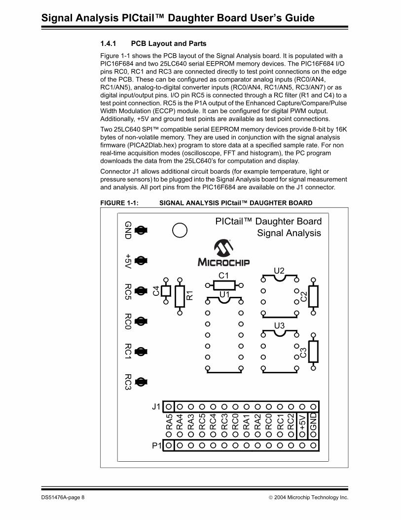
2.6 FFT (FAST FOURIER TRANSFORM)
The FFT displays the Fast Fourier Transformation of the data in the frequency domain.
This display is typically used to analyze AC signals or to help locate the source of AC
noise.
FIGURE 2-11: FFT DISPLAY
The size of the data set of the FFT analysis determines the resolution and accuracy of
the FFT. The accuracy is equal to:
Where:
n = number of converted bits
N = number of data points
In instances where the input signal is not periodic with respect to the sampling fre-
quency of the converter (as is the case with this tool), windowing algorithms are advan-
tageous when looking at FFT results. The windows that are available with the Signal
Analysis Application are the Blackman, Hamming, Hanning and Rectangular. Basically,
an FFT window is multiplied times the measured signal data set taken during the spec-
ified length of time of the conversion. Typically this multiple reduces the magnitude of
the beginning and end of the sample and consequently minimizing discontinuities seen
with the FFT calculation.
Blackman – Window has a bell-shaped characteristic similar to the Blackman-Harris
window. The peak resolution of this window is not as fine as the Hanning, but the
responses flares out less and the rejection of the sidelobes is better.
Hamming – Window has a bell-shaped characteristic. The initial samples from the
conversion data are multiplied by a small number as are the last samples. With this
window, the side lobes adjacent to the main lobes are lower than the results from the
Hanning Window.
Hanning – Window has a bell-shaped characteristic. The initial samples are multiplied
by zero as well a the latest samples. The samples between the beginning and end are
multiplied with the Hanning bell-shape curve. The side lobes of this window are farther
from main lobe as compared to the Hanning Windows. This window is typically used
for harmonic analysis of continuous time signals as well as random noise.
FFT Window Selection
FFT Accuracy = (4/(n√N)dB)
DS51476A-page 18 2004 Microchip Technology Inc.

Using the PICkit™ 1 Signal Analysis PC Application
Rectangular – Window is a rectangular shaped window. Every point of the time scale
is multiplied by a constant. This window provides the best frequency resolution with the
narrowest lobe width. Amplitude accuracy errors occur if frequency of observed signal
has a non-integer number of cycles in the FFT time record. Most typically, this window
is best used when viewing transients, impulses, pseudo-random noise and when the
input signal is correlated with the sampling frequency.
When the FFT windows are implemented there is a certain amount of energy that is
spread across adjacent frequency bins. This spreading is a result of converting
non-coherent signals and the particular window. Consequently, there is not a direct
correlation between the amplitude of the analog input signal to the A/D converter and
the height of the spur in the FFT analysis.
2.6.1 Glossary of Terms
Fundamental Frequency – The lowest frequency component in the Fourier
representation of a periodic quantity.
Noise Floor – The noise level at a referenced location and bandwidth.
SNR (Signal-to-Noise Ratio) – The ratio of relative power of the usable signal to the
noise present, expressed in decibels.
SINAD (Signal to (Noise + Distortion) Ratio) – S/(N+D) is the ratio of the rms value
of the actual input signal to the rms sum of all other spectral components or harmonics
below the Nyquist frequency, excluding DC. This software includes nine harmonics in
the calculation. Decibels is the unit of measure for S/(N+D).
THD (Total Harmonic Distortion) – The ratio in dB of the energy of a fundamental test
frequency to the energy of its harmonics appearing in the band of interest.
SFDR (Spurious Free Dynamic Range) – The difference in decibels between the
input signal and the next largest harmonic.
2004 Microchip Technology Inc. DS51476A-page 19

Signal Analysis PICtail™ Daughter Board User’s Guide
2.7 HISTOGRAM
The Histogram allows the user to observe the data taken from a conversion and deter-
mine the relative variation of the digital codes. The histogram plot shows the digital
codes on the X-Axis and the number of occurrences for each code on the Y-Axis. The
statical values of the data set are shown at the bottom of the window. The Span Control
locks in the number of codes shown on the X-Axis or allows the program to
automatically scale the axis for every conversion.
FIGURE 2-12: HISTOGRAM WINDOW
Forces the X axis to automatically
adjust to show all codes between
the smallest and largest codes in
the data set.
Forces display to show a certain
range of codes, independent on
the actual codes in the data set.
The range is set by the values in
the Max Code and Min Code
boxes.
Y-Axis shows the number of times
a certain code is returned.
DS51476A-page 20 2004 Microchip Technology Inc.

SIGNAL ANALYSIS PICtail™
DAUGHTER BOARD USER’S GUIDE
Chapter 3. Lesson Projects
3.1 INTRODUCTION
The Signal Analysis PICtail Daughter Board can capture a variety of DC and AC signals
from the RC0/AN4 I/O port pin of the PIC16F684 using the internal 10-bit ADC. Ensure
that the applied signal does not exceed 5V peak-to-peak. If the signal is DC, ensure
that the voltage levels do not fall below 0V or exceed +5V. If the signal is AC, DC
decouple the signal using a decoupling capacitor and ensure that the signal level does
not exceed the DC limits stated above. Lesson 1 demonstrates how a DC signal can
be displayed from a thermistor. Lesson 2 demonstrates how an AC signal can be
displayed from a photodiode.
In addition to capturing analog signals, the Signal Analysis PICtail Daughter Board can
generate low frequency sine waves from Pulse Width Modulated (PWM) signal from
the ECCP module. I/O port pin RC5 is connected to a low-pass RC filter (R1 and C4)
and made available as a test point on the edge of the PCB. Lesson 3 demonstrates
how a 125 Hz sine wave can be generated.
3.2 HIGHLIGHTS
The following lessons are discussed in this chapter:
• Lesson 1 – Thermistor
• Lesson 2 – Photodiode
• Lesson 3 – Pulse Width Modulated Generated Sine Wave
3.3 LESSON 1 – THERMISTOR
A thermistor is a resistor that changes resistance in response to temperature changes.
Some have a positive temperature coefficient where the resistance increases with
temperature and others have a negative coefficient. For temperature measurement
purposes, the Negative Temperature Coefficient (NTC) versions are more linear.
The simplest configuration is shown in Figure 3-1. It is a resistor divider network where
the thermistor and a second resistor are connected in series between ground and a
voltage reference. The voltage between the resistors varies with the temperature and
can be measured via an A2D Converter. Also, this configuration has the added benefit
that voltage increases with temperature.
The voltage at the center is given by ADC counts = 1024 * R/(R+Rt). In this example,
the thermistor specified for 10 kΩ at 25C. The bottom resistor is chosen to be 3.3 kΩ.
That means 254 ADC counts correlates to 25C. Since the ADC is referenced to 5V
(nominal) 254 counts * 5/1024 = 1.241V.
Start the PICkit 1 Signal Analysis PC Application. Select the Real Time button, click on
the Strip Chart icon, and then click Go. By changing the temperature of the thermistor,
the response can be observed in real-time on the strip chart display. An example
screen capture is shown in Figure 3-2.
For more information about thermistors, see Microchip Application Notes AN685,
AN689, AN867 and AN897, available on the PICkit 1 CD-ROM and on the Microchip
web site: www.microchip.com.
2004 Microchip Technology Inc. DS51476A-page 21

Signal Analysis PICtail™ Daughter Board User’s Guide
FIGURE 3-1: THERMISTOR SCHEMATIC
FIGURE 3-2: THERMISTOR STRIP CHART DISPLAY
+5V
Thermistor10 kΩ @ 25°C
3.3kΩ
RC0
DS51476A-page 22 2004 Microchip Technology Inc.

Lesson Projects
3.4 LESSON 2 – PHOTODIODE
A simple photodiode circuit can be constructed from the schematic shown in
Figure 3-3. D1 is a Panasonic PNZ334 PIN photodiode. U1 is Microchip Technology
MCP6001U op amp. R1 was chosen to be 64.9 kΩ so that VOUT ≈ 4.5V at the maximum
IS, and VOUT ≈ 0V at the minimum IS. C3 is a 0.1 µF capacitor for good supply bypass
performance. R2 and C2 form a low-pass filter for noise performance. Since the
maximum sample rate of the Signal Analysis PICtail Daughter Board is 5000 samples
per second (sps), the low-pass pole is set near 500 Hz.
R2 = 10.0 kΩ
C2 ≈ 1/(2π(500 Hz)(10.0 kΩ)) = 32 nF
The nearest standard value of 33 nF, giving
fRnCn = 1/(2π(10.0 kΩ)(33 nF)) = 482 kHz
Table 3-1 summarizes the final design values of the components in Figure 3-3.
Figure 3-4 through Figure 3-6 show screen captures from data acquisitions from the
photodiode placed 30 cm under a fluorescent desk lamp. The sample size was 1024
and the sample speed was set at 1000.
FIGURE 3-3: PHOTODIODE PICtail™ SCHEMATIC DIAGRAM
TABLE 3-1: PHOTODIODE PICtail™ COMPONENTS
U1
D1
R1
C1
R2
C2
C3
+5V
VOUT
PNZ334
MCP6001U0.1µ
Component Value/Part No. Size/Package
C1 18 pF SMD 0805
C2 33 nF SMD 0805
C3 0.1 µF SMD 0805
D1 PNZ334
Panasonic
Plastic Through-hole,
100 mil pitch
R1 64.9 kΩ, 1% SMD 0805
R2 10.0 kΩ SMD 0805
U1 MCP6001U SOT-23-5
2004 Microchip Technology Inc. DS51476A-page 23

Signal Analysis PICtail™ Daughter Board User’s Guide
FIGURE 3-4: PHOTODIODE OSCILLOSCOPE SCREEN CAPTURE
FIGURE 3-5: PHOTODIODE FFT SCREEN CAPTURE
DS51476A-page 24 2004 Microchip Technology Inc.

Lesson Projects
FIGURE 3-6: PHOTODIODE HISTOGRAM SCREEN CAPTURE
2004 Microchip Technology Inc. DS51476A-page 25

Signal Analysis PICtail™ Daughter Board User’s Guide
3.5 LESSON 3 – PULSE WIDTH MODULATED GENERATED SINE WAVE
A sine wave can be generated from a low-pass filtered Pulse Width Modulated (PWM)
signal. The duty cycle of the PWM signal is set to the magnitude of a sine wave at a
prescribed sample rate. The sample rate sets the frequency of the sine wave.
Figure 3-7 is an oscilloscope screen capture of the PWM signal. Persistence has been
set on to capture the varying duty cycle. Figure 3-8 is the resulting sine wave after the
PWM signal in Figure 3-7 has been low-pass filtered.
Source code and hex files are available on the CD-ROM.
FIGURE 3-7: MODULATED PWM SIGNAL (BEFORE FILTERING)
FIGURE 3-8: SINE WAVE (AFTER PWM FILTERING)
DS51476A-page 26 2004 Microchip Technology Inc.

SIGNAL ANALYSIS PICtail™
DAUGHTER BOARD USER’S GUIDE
Chapter 4. Troubleshooting
4.1 INTRODUCTION
This chapter describes common problems associated with using the Signal Analysis
PICtail Daughter Board and steps on how to resolve them.
4.2 COMMON PROBLEMS
4.2.1 Programmer Not Found
The PICkit 1 Signal Analysis PC Application was not able to communicate with the
PICkit 1 Flash Starter Kit. Check that the USB cable is connected to the PICkit 1 Flash
Starter Kit and the PC.
FIGURE 4-1: PROGRAMMER NOT FOUND ERROR MESSAGE
4.2.2 Insert Device
The PICkit 1 Signal Analysis PC Application was not able to communicate with the
target PICmicro device. Check that the Signal Analysis PICtail Daughter Board is
plugged into J3 of the PICkit 1 Flash Starter Kit. Check that a PICmicro device is
plugged into socket U1 of the Signal Analysis PICtail Daughter Board. Check and make
sure that the evaluation socket on the PICkit 1 board is empty.
FIGURE 4-2: INSERT DEVICE ERROR MESSAGE
2004 Microchip Technology Inc. DS51476A-page 27

Signal Analysis PICtail™ Daughter Board User’s Guide
4.2.3 End Device Must Have Acquisition Firmware Loaded
The PICkit 1 Signal Analysis PC Application was not able to communicate with the
firmware in the target PICmicro device on the Signal Analysis PICtail Daughter Board.
Ensure that PICA2Dlab.hex has been programmed into the Signal Analysis PICtail
Daughter Board.
FIGURE 4-3: END DEVICE ACQUISITION FIRMWARE LOADED ERROR
MESSAGE
DS51476A-page 28 2004 Microchip Technology Inc.
SIGNAL ANALYSIS PICtail™
DAUGHTER BOARD USER’S GUIDE
Appendix A. Hardware Schematics
A.1 INTRODUCTION
This appendix contains the Signal Analysis PICtail Daughter Board Hardware
Schematic Diagram.
2004 Microchip Technology Inc. DS51476A-page 29
Signal Analysis PICtail™ Daughter Board User’s Guide
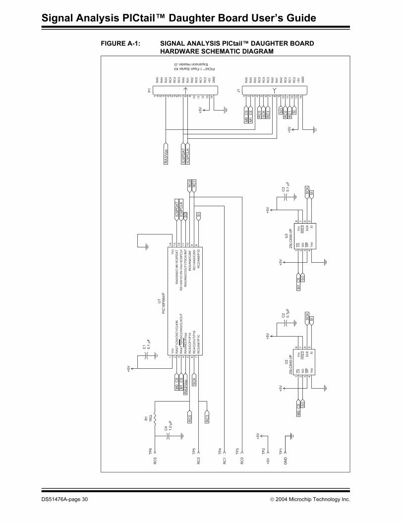
FIGURE A-1: SIGNAL ANALYSIS PICtail™ DAUGHTER BOARD
HARDWARE SCHEMATIC DIAGRAM
14
13
12
11
104321 98765
14
13
12
11
104321 98765
1 2 3 45678
1 2 3 45678
1 2 3 4
8
5 6 7
910
11
12
13
14
CS
WP
Vss
Vcc
HO
LD
SC
K
SO
SI
CS
WP
Vss
Vcc
HO
LD
SC
K
SO
SI
RA
5/T
1C
KI/
OS
C1
/CL
KIN
VS
S
RA
0/A
N0
/C1
IN+/I
CS
PD
AT
RA
1/A
N1
/C1
IN-/
VR
EF/I
CS
PC
LK
RA
2/A
N2
/CO
UT
1/T
0C
KI/
INT
VD
D
RA
4/T
1G
/OS
C2
/AN
3/C
LK
OU
T
RA
3/M
CL
R/V
pp
RC
5/C
CP
1/P
1A
RC
4/C
2O
UT
/P1
B
RC
3/A
N7
/P1
C
RC
0/A
N4
/C2
IN+
RC
1/A
N5
/C2
IN-
RC
2/A
N6
/P1
D
+5V
+5V
+5V
+5V
+5V
+5V
+5V
+5V
M1_C
S
M0_C
S
RC
5
RC
3
SC
K
RC
5
RC
3
RC
1
RC
0
RC
1
RC
0
SI
SO
RA
3/V
pp
RA
3/V
pp
M0_C
S
M0_C
S
SI
M1_C
S
M1_C
S
SC
K
SOIC
SP
DA
T
ICS
PC
LK
ICS
PC
LK
ICS
PD
AT
SC
K
SI
SO
SC
K
SI
SO
C1
0.1
µF
C2
0.1
µFC
3
0.1
µF
C4
1.0
µF
J1
P1
R1
1K
Ω
TP
1
GN
D
TP
2
+5V
TP
3
RC
0
TP
4
RC
1
TP
5
RC
3
TP
6
RC
5
U2
25LC
640-I
/P
U3
25LC
640-I
/P
U1
PIC
16F
684/P
RA
5
RA
4
RA
3
RC
5
RC
4
RC
3
RA
0
RA
1
RA
2
RC
0
RC
1
RC
2
+5
V
GN
D
PICkit™ 1 Flash Starter Kit
Expansion Header J3
RA
5
RA
4
RA
3
RC
5
RC
4
RC
3
RA
0
RA
1
RA
2
RC
0
RC
1
RC
2
+5
V
GN
D
DS51476A-page 30 2004 Microchip Technology Inc.

Hardware Schematics
NOTES:
2004 Microchip Technology Inc. DS51476A-page 31

DS51476A-page 32 2004 Microchip Technology Inc.
AMERICAS
Corporate Office2355 West Chandler Blvd.Chandler, AZ 85224-6199Tel: 480-792-7200 Fax: 480-792-7277Technical Support: 480-792-7627Web Address: www.microchip.com
Atlanta3780 Mansell Road, Suite 130Alpharetta, GA 30022Tel: 770-640-0034 Fax: 770-640-0307
Boston2 Lan Drive, Suite 120Westford, MA 01886Tel: 978-692-3848 Fax: 978-692-3821
Chicago333 Pierce Road, Suite 180Itasca, IL 60143Tel: 630-285-0071 Fax: 630-285-0075
Dallas4570 Westgrove Drive, Suite 160Addison, TX 75001Tel: 972-818-7423 Fax: 972-818-2924
DetroitTri-Atria Office Building 32255 Northwestern Highway, Suite 190Farmington Hills, MI 48334Tel: 248-538-2250Fax: 248-538-2260
Kokomo2767 S. Albright Road Kokomo, IN 46902Tel: 765-864-8360Fax: 765-864-8387
Los Angeles18201 Von Karman, Suite 1090Irvine, CA 92612Tel: 949-263-1888 Fax: 949-263-1338
San Jose1300 Terra Bella AvenueMountain View, CA 94043Tel: 650-215-1444Fax: 650-961-0286
Toronto6285 Northam Drive, Suite 108Mississauga, Ontario L4V 1X5, CanadaTel: 905-673-0699 Fax: 905-673-6509
ASIA/PACIFIC
AustraliaSuite 22, 41 Rawson StreetEpping 2121, NSWAustraliaTel: 61-2-9868-6733 Fax: 61-2-9868-6755
China - BeijingUnit 706BWan Tai Bei Hai Bldg.No. 6 Chaoyangmen Bei Str. Beijing, 100027, ChinaTel: 86-10-85282100 Fax: 86-10-85282104
China - ChengduRm. 2401-2402, 24th Floor, Ming Xing Financial TowerNo. 88 TIDU StreetChengdu 610016, ChinaTel: 86-28-86766200 Fax: 86-28-86766599
China - FuzhouUnit 28F, World Trade PlazaNo. 71 Wusi RoadFuzhou 350001, ChinaTel: 86-591-7503506 Fax: 86-591-7503521
China - Hong Kong SARUnit 901-6, Tower 2, Metroplaza223 Hing Fong RoadKwai Fong, N.T., Hong KongTel: 852-2401-1200 Fax: 852-2401-3431
China - ShanghaiRoom 701, Bldg. BFar East International PlazaNo. 317 Xian Xia RoadShanghai, 200051Tel: 86-21-6275-5700 Fax: 86-21-6275-5060
China - ShenzhenRm. 1812, 18/F, Building A, United PlazaNo. 5022 Binhe Road, Futian DistrictShenzhen 518033, ChinaTel: 86-755-82901380 Fax: 86-755-8295-1393
China - ShundeRoom 401, Hongjian Building, No. 2 Fengxiangnan Road, Ronggui Town, ShundeDistrict, Foshan City, Guangdong 528303, ChinaTel: 86-757-28395507 Fax: 86-757-28395571
China - QingdaoRm. B505A, Fullhope Plaza,No. 12 Hong Kong Central Rd.Qingdao 266071, ChinaTel: 86-532-5027355 Fax: 86-532-5027205
IndiaDivyasree Chambers1 Floor, Wing A (A3/A4)No. 11, O’Shaugnessey RoadBangalore, 560 025, IndiaTel: 91-80-22290061 Fax: 91-80-22290062
JapanBenex S-1 6F3-18-20, ShinyokohamaKohoku-Ku, Yokohama-shiKanagawa, 222-0033, JapanTel: 81-45-471- 6166 Fax: 81-45-471-6122
Korea168-1, Youngbo Bldg. 3 FloorSamsung-Dong, Kangnam-KuSeoul, Korea 135-882Tel: 82-2-554-7200 Fax: 82-2-558-5932 or 82-2-558-5934
Singapore200 Middle Road#07-02 Prime CentreSingapore, 188980Tel: 65-6334-8870 Fax: 65-6334-8850
TaiwanKaohsiung Branch30F - 1 No. 8Min Chuan 2nd RoadKaohsiung 806, TaiwanTel: 886-7-536-4818Fax: 886-7-536-4803
TaiwanTaiwan Branch11F-3, No. 207Tung Hua North RoadTaipei, 105, TaiwanTel: 886-2-2717-7175 Fax: 886-2-2545-0139
EUROPEAustriaDurisolstrasse 2A-4600 WelsAustriaTel: 43-7242-2244-399Fax: 43-7242-2244-393
DenmarkRegus Business CentreLautrup hoj 1-3Ballerup DK-2750 DenmarkTel: 45-4420-9895 Fax: 45-4420-9910
FranceParc d’Activite du Moulin de Massy43 Rue du Saule TrapuBatiment A - ler Etage91300 Massy, FranceTel: 33-1-69-53-63-20 Fax: 33-1-69-30-90-79
GermanySteinheilstrasse 10D-85737 Ismaning, GermanyTel: 49-89-627-144-0 Fax: 49-89-627-144-44
ItalyVia Quasimodo, 1220025 Legnano (MI)Milan, Italy Tel: 39-0331-742611 Fax: 39-0331-466781
NetherlandsWaegenburghtplein 4NL-5152 JR, Drunen, NetherlandsTel: 31-416-690399 Fax: 31-416-690340
United Kingdom505 Eskdale RoadWinnersh TriangleWokingham Berkshire, England RG41 5TUTel: 44-118-921-5869Fax: 44-118-921-5820
05/28/04
WORLDWIDE SALES AND SERVICE