mm7150-pictail user's guide - farnell element14 · no licenses are conveyed, impl ......
TRANSCRIPT
2014 - 2015 Microchip Technology Inc. DS50002322B
MM7150-PICTAILMotion Module PICtail on
Explorer 16 Development BoardUser’s Guide

DS50002322B-page 2 2014 - 2015 Microchip Technology Inc.
Information contained in this publication regarding device applications and the like is provided only for your convenience and may besuperseded by updates. It is your responsibility to ensure that your application meets with your specifications. MICROCHIP MAKES NOREPRESENTATIONS OR WARRANTIES OF ANY KIND WHETHER EXPRESS OR IMPLIED, WRITTEN OR ORAL, STATUTORY OROTHERWISE, RELATED TO THE INFORMATION, INCLUDING BUT NOT LIMITED TO ITS CONDITION, QUALITY, PERFORMANCE,MERCHANTABILITY OR FITNESS FOR PURPOSE. Microchip disclaims all liability arising from this information and its use. Use of Micro-chip devices in life support and/or safety applications is entirely at the buyer’s risk, and the buyer agrees to defend, indemnify and holdharmless Microchip from any and all damages, claims, suits, or expenses resulting from such use. No licenses are conveyed, implicitly orotherwise, under any Microchip intellectual property rights.
Trademarks
The Microchip name and logo, the Microchip logo, dsPIC, FlashFlex, flexPWR, JukeBlox, KEELOQ, KEELOQ logo, Kleer, LANCheck, MediaLB, MOST, MOST logo, MPLAB, OptoLyzer, PIC, PICSTART, PIC32 logo, RightTouch, SpyNIC, SST, SST Logo, SuperFlash and UNI/O are registered trademarks of Microchip Technology Incorporated in the U.S.A. and other countries.
The Embedded Control Solutions Company and mTouch are registered trademarks of Microchip Technology Incorporated in the U.S.A.
Analog-for-the-Digital Age, BodyCom, chipKIT, chipKIT logo, CodeGuard, dsPICDEM, dsPICDEM.net, ECAN, In-Circuit Serial Programming, ICSP, Inter-Chip Connectivity, KleerNet, KleerNet logo, MiWi, MPASM, MPF, MPLAB Certified logo, MPLIB, MPLINK, MultiTRAK, NetDetach, Omniscient Code Generation, PICDEM, PICDEM.net, PICkit, PICtail, RightTouch logo, REAL ICE, SQI, Serial Quad I/O, Total Endurance, TSHARC, USBCheck, VariSense, ViewSpan, WiperLock, Wireless DNA, and ZENA are trademarks of Microchip Technology Incorporated in the U.S.A. and other countries.
SQTP is a service mark of Microchip Technology Incorporated in the U.S.A.
Silicon Storage Technology is a registered trademark of Microchip Technology Inc. in other countries.
GestIC is a registered trademarks of Microchip Technology Germany II GmbH & Co. KG, a subsidiary of Microchip Technology Inc., in other countries.
All other trademarks mentioned herein are property of their respective companies.
© 2014 - 2015, Microchip Technology Incorporated, Printed in the U.S.A., All Rights Reserved.
ISBN: 9781632770783
Note the following details of the code protection feature on Microchip devices:
• Microchip products meet the specification contained in their particular Microchip Data Sheet.
• Microchip believes that its family of products is one of the most secure families of its kind on the market today, when used in the intended manner and under normal conditions.
• There are dishonest and possibly illegal methods used to breach the code protection feature. All of these methods, to our knowledge, require using the Microchip products in a manner outside the operating specifications contained in Microchip’s Data Sheets. Most likely, the person doing so is engaged in theft of intellectual property.
• Microchip is willing to work with the customer who is concerned about the integrity of their code.
• Neither Microchip nor any other semiconductor manufacturer can guarantee the security of their code. Code protection does not mean that we are guaranteeing the product as “unbreakable.”
Code protection is constantly evolving. We at Microchip are committed to continuously improving the code protection features of ourproducts. Attempts to break Microchip’s code protection feature may be a violation of the Digital Millennium Copyright Act. If such actsallow unauthorized access to your software or other copyrighted work, you may have a right to sue for relief under that Act.
Microchip received ISO/TS-16949:2009 certification for its worldwide headquarters, design and wafer fabrication facilities in Chandler and Tempe, Arizona; Gresham, Oregon and design centers in California and India. The Company’s quality system processes and procedures are for its PIC® MCUs and dsPIC® DSCs, KEELOQ® code hopping devices, Serial EEPROMs, microperipherals, nonvolatile memory and analog products. In addition, Microchip’s quality system for the design and manufacture of development systems is ISO 9001:2000 certified.
QUALITY MANAGEMENT SYSTEM CERTIFIED BY DNV
== ISO/TS 16949 ==
2014 - 2015 Microchip Technology Inc. DS50002322B-page 3
Object of Declaration: MM7150-PICTAIL Motion Module PICtail on Explorer 16 Development Board
MM7150-PICTAIL ON EXPLORER 16DEVELOPMENT BOARD USER’S GUIDE
Table of Contents
Preface ........................................................................................................................... 6Introduction............................................................................................................ 6
Document Layout .................................................................................................. 6
Audience ............................................................................................................... 7
Reference Documents........................................................................................... 7
Glossary ................................................................................................................ 7
The Microchip Web Site ........................................................................................ 7
Development Systems Customer Change Notification Service ............................ 8
Customer Support ................................................................................................. 8
Document Revision History ................................................................................... 9
Chapter 1. Hardware Setup1.1 Hardware Requirements .............................................................................. 101.2 Preparing the Explorer 16 Development Board ............................................ 101.3 Hardware Connections for MM7150-PICTAIL to Explorer 16 Development
Board ...................................................................................................... 10
Chapter 2. Software/Firmware Setup2.1 Software/Firmware requirements ................................................................. 122.2 MPLABX Project: .......................................................................................... 12
Chapter 3. Demo Setup3.1 Running the Motion demo ............................................................................ 153.2 Sensor Data Display ..................................................................................... 163.3 Sleep/Wake .................................................................................................. 163.4 Flash Update ................................................................................................ 17
3.4.1 Flash Update command ............................................................................ 18
Chapter 4. Troubleshooting4.1 Failure to Display Welcome Screen ............................................................. 204.2 Error Handling .............................................................................................. 21
4.2.1 General Error Handling for VREG functions .............................................. 214.2.2 I2C Error Handling .................................................................................... 224.2.3 Error Definitions (from source/headers/err.h) ............................................ 23
Appendix A. Code StructureA.1 Directory structure ........................................................................................ 24A.2 Program Flow ............................................................................................... 26
A.3.1 Main.c ....................................................................................................... 26A.3.2 Configuring and Initializing MM7150 Motion Module ................................ 26A.3.3 Enabling Sensors and Reading data ........................................................ 26
2014 - 2015 Microchip Technology Inc. DS50002322B-page 4

Appendix B. Reference Schematic & Bill of MaterialsB.1 MM7150-PICTAIL Daughter card ................................................................ 27
B.1.1 Bill of Materials .......................................................................................... 27B.1.2 Reference Schematic ................................................................................ 27
Worldwide Sales and Service .................................................................................... 29
2014 - 2015 Microchip Technology Inc. DS50002322B-page 5
MM7150-PICTAIL ON EXPLORER 16DEVELOPMENT BOARD USER’S GUIDE
Preface
INTRODUCTION
This chapter contains general information that will be useful to know before using the MM7150 Motion Module & it’s MM7150-PICTAIL PICtail Daughter Card with the Explorer 16 development board (Part #: DM240001) to run the demo and sample code. Items discussed in this chapter include:
• Document Layout
• Audience
• Reference Documents
• Glossary
• The Microchip Web Site
• Development Systems Customer Change Notification Service
• Customer Support
• Document Revision History
DOCUMENT LAYOUT
This document describes how to use the MM7150-PICTAIL Motion Module PICtail with Explorer 16 Development Board to perform the demo and sample code. The manual layout is as follows:
• Chapter 1. “Hardware Setup” – Provides hardware setting information.
• Chapter 2. “Software/Firmware Setup” – Provides software and firmware set-ting and build information.
• Chapter 3. “Demo Setup” – Includes demonstration procedures.
• Chapter 4. “Troubleshooting” – Provides troubleshooting information.
• Appendix A. “Code Structure” – Provides sample code structure information.
NOTICE TO CUSTOMERS
All documentation becomes dated, and this manual is no exception. Microchip tools and documentation are constantly evolving to meet customer needs, so some actual dialogs and/or tool descriptions may differ from those in this document. Please refer to our web site (www.microchip.com) to obtain the latest documentation available.
Documents are identified with a “DS” number. This number is located on the bottom of each page, in front of the page number. The numbering convention for the DS number is “DSXXXXXA”, where “XXXXX” is the document number and “A” is the revision level of the document.
For the most up-to-date information on development tools, see the MPLAB® IDE online help. Select the Help menu, and then Topics to open a list of available online help files.
2014 - 2015 Microchip Technology Inc. DS50002322B-page 6

Preface
• Appendix B. “Reference Schematic & Bill of Materials” – Provides MM7150-PICTAIL PICtail adapter reference schematic & bill of materials informa-tion.
AUDIENCE
This document is written for developers who are familiar with 9-axis motion sensors applications. The purpose of this document is to describe the functions and use of the MM7150-PICTAIL Motion Module PICtail with Explorer 16 Development Board to per-form the demos and sample code functions as described in the Host API Design for MM7150 Application Note.
REFERENCE DOCUMENTS
• DS00001885A - SSC7150 Motion Coprocessor Data Sheet
• DS00001888A - MM7150 Motion Module Data Sheet
• DS00001873A - Host API Design for MM7150 Motion Module Application Note
GLOSSARY
This section describes glossary terms and acronyms used in this document.
THE MICROCHIP WEB SITE
Microchip provides online support via our web site at www.microchip.com. This web site is used as a means to make files and information easily available to customers. Accessible by using your favorite Internet browser, the web site contains the following information:
• Product Support – Data sheets and errata, application notes and sample programs, design resources, user’s guides and hardware support documents, latest software releases and archived software
• General Technical Support – Frequently Asked Questions (FAQs), technical support requests, online discussion groups, Microchip consultant program member listing
• Business of Microchip – Product selector and ordering guides, latest Microchip press releases, listing of seminars and events, listings of Microchip sales offices, distributors and factory representatives
Note: Please contact your Microchip representative for the above documents and availability.
TERM DEFINITION
EVB Evaluation Board
HID Human Interface Device
I2C Inter-Integrated Circuit
USB Universal Serial Bus
EC Embedded Controller
SF Sensor Fusion
2014 - 2015 Microchip Technology Inc. DS50002322B-page 7

MM7150-PICTAIL Motion Module PICtail with Explorer 16 Development Board User’s Guide
DEVELOPMENT SYSTEMS CUSTOMER CHANGE NOTIFICATION SERVICE
Microchip’s customer notification service helps keep customers current on Microchip products. Subscribers will receive e-mail notification whenever there are changes, updates, revisions or errata related to a specified product family or development tool of interest.
To register, access the Microchip web site at www.microchip.com, click on Customer Change Notification and follow the registration instructions.
The Development Systems product group categories are:• Compilers – The latest information on Microchip C compilers, assemblers, linkers
and other language tools. These include all MPLAB C compilers; all MPLAB assemblers (including MPASM assembler); all MPLAB linkers (including MPLINK object linker); and all MPLAB librarians (including MPLIB object librarian).
• Emulators – The latest information on Microchip in-circuit emulators.This includes the MPLAB REAL ICE and MPLAB ICE 2000 in-circuit emulators.
• In-Circuit Debuggers – The latest information on the Microchip in-circuit debuggers. This includes MPLAB ICD 3 in-circuit debuggers and PICkit 3 debug express.
• MPLAB IDE – The latest information on Microchip MPLAB IDE, the Windows Integrated Development Environment for development systems tools. This list is focused on the MPLAB IDE, MPLAB IDE Project Manager, MPLAB Editor and MPLAB SIM simulator, as well as general editing and debugging features.
• Programmers – The latest information on Microchip programmers. These include production programmers such as MPLAB REAL ICE in-circuit emulator, MPLAB ICD 3 in-circuit debugger and MPLAB PM3 device programmers. Also included are nonproduction development programmers such as PICSTART Plus and PIC-kit 2 and 3.
CUSTOMER SUPPORT
Users of Microchip products can receive assistance through several channels:
• Distributor or Representative
• Local Sales Office
• Field Application Engineer (FAE)
• Technical Support
Customers should contact their distributor, representative or field application engineer (FAE) for support. Local sales offices are also available to help customers. A listing of sales offices and locations is included in the back of this document.
Technical support is available through the web site at: http://www.microchip.com/support
DS50002322B-page 8 2014 - 2015 Microchip Technology Inc.

Preface
DOCUMENT REVISION HISTORY
Revision Section/Figure/Entry Correction
DS50002322B (02-18-15) • Added section 3.4 for Sleep/Wake feature
• Added section 3.5 for Flash Update feature, updated corresponding sec-tions
• Changed UART baud rate from custom 125000 to standard 19200
• Updated all the figures to show the v1.3.2 sample code
• Updated the correct Document Numbers in the Reference Section
• Added section 1.1 for hardware requirements
• Added section 2.1 for software/firmware requirements
• Section 3.2 “Calibrating Sensors” removed
DS50002322A (11-07-14) Initial Release
2014 - 2015 Microchip Technology Inc. DS50002322B-page 9
MM7150-PICTAIL ON EXPLORER 16DEVELOPMENT BOARD USER’S GUIDE
Chapter 1. Hardware Setup
1.1 HARDWARE REQUIREMENTS
• Microchip Explorer 16 Development Board
• Microchip MM7150-PICtail Motion Module PICtail Board
• Microchip PICKit3 or ICD3 or RealICE debugger
• Null-Modem Serial Cable
• USB-to-Serial Adapter
1.2 PREPARING THE EXPLORER 16 DEVELOPMENT BOARD
• Insert PIM PIC24FJ128GA010 at Explorer 16 U1A socket
• Insert strap J7 for PIC24
• S2 switch selected for PIM
• Connect MPLAB ICD3 (or REAL ICE) In-Circuit Debugger module from HOST PC to JP1
• Connect USB-to-Serial Adapter capable of 19200 baud rate from HOST USB Port to Explorer 16 P1
- USB-to-Serial Adapter such as: USB-to-Serial Adapter from Staples #18762 http://www.staples.com/Staples-USB-to-Serial-Adapter/product_837560
• Power Supply (+9V) at J12
1.3 HARDWARE CONNECTIONS FOR MM7150-PICTAIL TO EXPLORER 16 DEVELOPMENT BOARD
Note: Configure Terminal Emulation Software (ex. Tera Term) for 19200 baud, 8 bits, No Parity, 1 Stop Bit, No Flow Control.
TABLE-1: CONNECTION SUMMARY BETWEEN MM7150-PICTAIL TO EXP16 BOARD
Signal Name MM7150 Module Pin Exp16 J6 Header Name Exp 16 J6 Header Pin
+3.3V 7 +3.3V 21
GND 8 GND 9
HIDI2C_HOST_INT 4 RE8/INT1 18
HIDI2C_HOST_DAT 16 RG3/SDA1 8
HIDI2C_HOST_CLK 15 RG2/SCL1 6
HOST_TO_SH_WAKE 1 RE9 17
Note: Before attempting to connect the MM7150-PICTAIL with PICtail™ Plus Edge connector module to the Explorer 16 board, it is crucial that the power supply to the Explorer 16 be disconnected. Failure to do so may damage the MM7150 Motion Module.
2014 - 2015 Microchip Technology Inc. DS50002322B-page 10

Hardware Setup
The MM7150-PICTAIL can be installed directly into the Explorer 16 Board. Insert the MM7150-PICTAIL into the PICtail™ header J5 with pin 1 of the module lining up with pin 1 of the header, as seen in Figure 1.
FIGURE-1: DIRECT CONNECTION OF MM7150-PICTAIL TO THE EXPLORER 16 PICTAIL™ HEADER.
2014 - 2015 Microchip Technology Inc. DS50002322B-page 11
MM7150-PICTAIL ON EXPLORER 16DEVELOPMENT BOARD USER’S GUIDE
Chapter 2. Software/Firmware Setup
2.1 SOFTWARE/FIRMWARE REQUIREMENTS
• Microchip MPLABX IDE v2.06 or later
• Microchip XC16 Compiler v1.24 or later
• Explorer 16 Host Sample Code Firmware
- Version v1.3.2 or later (older version may not support some functions like flash update and wake/sleep)
• SSC7150 Motion Coprocessor Firmware
- The firmware can be updated using the flash update feature as described in Section 3.4 “Flash Update”
- The firmware binary object code is encrypted and the update process is secured.
2.2 MPLABX PROJECT:
• Start MPLABX IDE
Note: The latest sample code is available at www.microchip.com/motion or please contact your Microchip representative for more information.
Note: The latest firmware binary file is available at www.microchip.com/motion or please contact your Microchip representative for more information.
2014 - 2015 Microchip Technology Inc. DS50002322B-page 12
Software/Firmware Setup
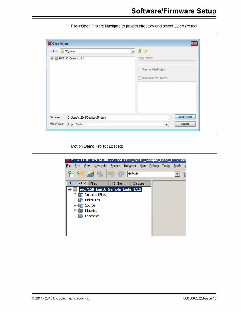
• File->Open Project Navigate to project directory and select Open Project
• Motion Demo Project Loaded:
2014 - 2015 Microchip Technology Inc. DS50002322B-page 13

MM7150-PICTAIL Motion Module PICtail with Explorer 16 Development Board User’s Guide
• With Explorer 16 power applied, to make the project and download to Explorer 16 flash, select:
• Output screen during build process:
DS50002322B-page 14 2014 - 2015 Microchip Technology Inc.

MM7150-PICTAIL ON EXPLORER 16DEVELOPMENT BOARD USER’S GUIDE
Chapter 3. Demo Setup
3.1 RUNNING THE MOTION DEMO
Once the program has been built and downloaded/programmed successfully to Explorer 16 Flash, the user should observe a sequence of LED flashes on the Explorer 16 board’s LED panel.
The user should then observe the following message on the Explorer 16 board’s LCD screen:
SF demo: SSC7150Select sensor:Additionally the following message will appear in the serial terminal window on the con-nected computer:
Microchip Sensor Fusion Demo: SSC7150 + Explorer 16 Board v1.3.2Select Sensor:Once this message has been displayed, the user can begin navigating the user menu using the Explorer 16 push buttons (S3/S6/S5/S4). The buttons are coded as follows:
Note: Using a debugger will necessitate cycling power to the connected MM7150-PICTAIL to reset its onboard EC (embedded controller). The eas-iest way to accomplish this while debugging code is to remove/install power to the Explorer 16 Development board with the MM7150-PICTAIL installed in J5 header. DO NOT attempt to unplug the MM7150-PICTAIL while power is applied to it through its connection to the Explorer 16 Development board. This can cause a power spike to the MM7150-PICTAIL and cause it to become inoperative.
2014 - 2015 Microchip Technology Inc. DS50002322B-page 15

MM7150-PICTAIL Motion Module PICtail with Explorer 16 Development Board User’s Guide
As the UP/DOWN buttons are pressed, the Explorer 16 LCD screen will refresh and change the position of the selection cursor (“>") in a list of available sensor types. The output to the serial monitor will also change to indicate the current sensor type which can be selected by pressing the (S5) SELECT button. Once the user selects a sensor from the menu, the sensor data output will be displayed and updated on both the LCD and serial monitor.
3.2 SENSOR DATA DISPLAY
Once calibrated the active sensors on the MM7150 motion module will send updates to the PIC24 on the Explorer 16 board running the application program via I2C in the form of HID packets including all relevant dimensions of data to be retrieved from the device. These sensor readings will be displayed on the LCD (as well as the COM port in a ‘linear’ formatting):
1D data: 79.0 3D data: X: 50.3 Y: 75.6 Z: -32.94D data: X: 1.021 Y:-.642 Z:-.458 W: .348
Sample output to COM port running Tera Term serial emulator:
The sensor data is updated to the display every time a data register has changed since the previous update.
Note: Significant digits will vary based on resolution of specific sensor. This reso-lution can be determined by the unit exponent scaling factor. Serial data will always be displayed to 3 significant digits.
DS50002322B-page 16 2014 - 2015 Microchip Technology Inc.

Demo Setup
3.3 SLEEP/WAKE
The MM7150 motion module can be set to enter deep sleep to achieve its lowest power consumption. In the Explorer 16 sample code this can be accomplished by selecting the SLEEP command from the main menu. The Explorer 16 host will send a POW-ER_OFF command through the I2C interface. As a result of this SLEEP command the MM7150 motion coprocessor is halted and the I2C interface is stopped.
Select the WAKE command from the Explorer 16 main menu to wake the MM7150 motion module. This command will toggle the HOST_TO_SH_WAKE signal to alert the MM7150 to wake, send the POWER_ON command via I2C interface, and wait the required time to allow the MM7150 to fully wake and allow sensor activity to resume.
The sleep/wake process requires that certain timing constraints must be observed (shown below in Table-2:).
3.4 FLASH UPDATE
The MM7150 motion module firmware can be updated with the appropriate binary image (please refer to Section 2.1 “Software/Firmware requirements” for more information) by selecting Flash Update from the Explorer 16 main menu. The Explorer 16 sample code will reset the MM7150 module into a state able to accept the new binary image, download and CRC-check a valid binary image, program new MM7150 firmware binary via I2C interface, and finally perform image verification.
TABLE-2: SLEEP / WAKE TIMING CONSTRAINTS
Delay period Reason
1 Required delay between sending the SLEEP command & toggling WAKE
70ms This is required for the coefficient write in flash during D3 plus other house-keeping activities to go into D3 state
2 Required delay between toggling (3 µs min) the wake signal and sending power ON command
11ms This is required for clock source switch-ing after coming out of D3 state
3 Required delay between D3 wake and enumera-tion sequence start
30ms This is required for sensor initialization after D3 state
Note: The Explorer 16’s UART connection will be used to download the flash update binary and, as such, must be connected to a HOST PC running a terminal emulator (such as Tera Term as described in Section 1.2 “Preparing the Explorer 16 Development Board”).
2014 - 2015 Microchip Technology Inc. DS50002322B-page 17
MM7150-PICTAIL Motion Module PICtail with Explorer 16 Development Board User’s Guide
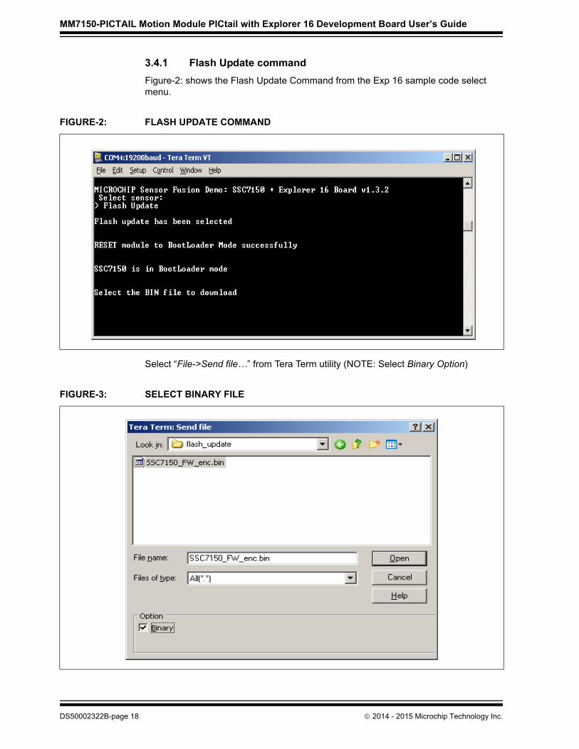
3.4.1 Flash Update command
Figure-2: shows the Flash Update Command from the Exp 16 sample code select menu.
Select “File->Send file…” from Tera Term utility (NOTE: Select Binary Option)
FIGURE-2: FLASH UPDATE COMMAND
FIGURE-3: SELECT BINARY FILE
DS50002322B-page 18 2014 - 2015 Microchip Technology Inc.

Demo Setup
Following successful completion of the flash update procedure (or if any error is encountered), the Explorer 16 must be power cycled.
FIGURE-4: DOWNLOADING BINARY IMAGE
FIGURE-5: FLASH UPDATE SUCCESSFUL COMPLETION
2014 - 2015 Microchip Technology Inc. DS50002322B-page 19

MM7150-PICTAIL ON EXPLORER 16DEVELOPMENT BOARD USER’S GUIDE
Chapter 4. Troubleshooting
This chapter describes troubleshooting potential issues and fixes.
4.1 FAILURE TO DISPLAY WELCOME SCREEN
If the welcome message fails to display on the Explorer 16 LCD screen and error mes-sages depicted below appear in the debugger’s output (using Microchip ICD3 or REAL ICE debugger for instance), the most likely cause is a failure to disconnect and recon-nect power to the MM7150-PICTAIL. This is accomplished by disconnecting and recon-necting power to the Explorer 16 board before restarting the demo. This process serves as a ‘hard reset’ for the SSC7150 on the MM7150-PICTAIL, allowing I2C communica-tion to reinitialize and restart.
FIGURE-6: ERROR MESSAGE IN DEBUGGER’S TAB
Note: If user is running on a different debugger (eg: ICD3, ICD2 etc.) the message would appear in that debugger’s output tab.
2014 - 2015 Microchip Technology Inc. DS50002322B-page 20
Troubleshooting
4.2 ERROR HANDLING
4.2.1 General Error Handling for VREG functions
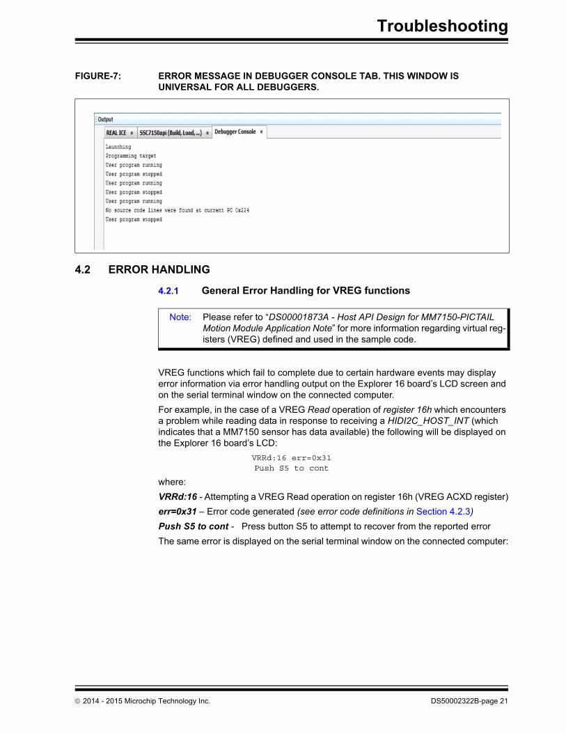
VREG functions which fail to complete due to certain hardware events may display error information via error handling output on the Explorer 16 board’s LCD screen and on the serial terminal window on the connected computer.
For example, in the case of a VREG Read operation of register 16h which encounters a problem while reading data in response to receiving a HIDI2C_HOST_INT (which indicates that a MM7150 sensor has data available) the following will be displayed on the Explorer 16 board’s LCD:
VRRd:16 err=0x31Push S5 to cont
where:
VRRd:16 - Attempting a VREG Read operation on register 16h (VREG ACXD register)
err=0x31 – Error code generated (see error code definitions in Section 4.2.3)
Push S5 to cont - Press button S5 to attempt to recover from the reported error
The same error is displayed on the serial terminal window on the connected computer:
FIGURE-7: ERROR MESSAGE IN DEBUGGER CONSOLE TAB. THIS WINDOW IS UNIVERSAL FOR ALL DEBUGGERS.
Note: Please refer to “DS00001873A - Host API Design for MM7150-PICTAIL Motion Module Application Note” for more information regarding virtual reg-isters (VREG) defined and used in the sample code.
2014 - 2015 Microchip Technology Inc. DS50002322B-page 21

MM7150-PICTAIL Motion Module PICtail with Explorer 16 Development Board User’s Guide
4.2.2 I2C Error Handling
Upper level functions which employ I2C function calls for the Explorer 16 board’s PIC24 to MM7150 interface that fail to complete will display error information. The I2C error handling display is output on the Explorer 16 board’s LCD screen and on the serial ter-minal window on the connected computer.
For example, in the case of an i2cIO operation which encounters an issue, wherein the MM7150 fails to ACK properly, the following will be displayed on the Explorer 16 board’s LCD:
i2c error=0x29POR Exp16 Board
where:
i2c - error occurred in i2cIO() function
error=0x29 – error code generated (see error code definitions in Section 4.2.3)
POR Exp16 Board - Power On Reset Explorer 16 board (and connected MM7150-PICTAIL)
The same error is displayed on the serial terminal window on the connected computer.
FIGURE-8: SERIAL TERMINAL GENERAL ERROR HANDLING DISPLAY
TABLE-3: GENERAL ERROR HANDLER FUNCTION ABBREVIATION
Function Error Handler Output Abbreviation
VREG_init( ) Vini
HOST_SF_LIB_VREG_read( ) VRRd
HOST_SF_LIB_VREG_write ( ) VRWr
I2cIO( ) i2c
Note: Most, if not all, I2C errors are hardware dependent. As this sample code is specific to the PIC24 on the Explorer 16 board, I2C errors are simply flagged as an error to illustrate where the issue was encountered. For this demo, in the rare event that a fully functional I2C interface encounters an error, the error “recovery” method will require resetting the Explorer 16 board and, hence, the connected MM7150-PICTAIL.
DS50002322B-page 22 2014 - 2015 Microchip Technology Inc.

Troubleshooting
4.2.3 Error Definitions (from source/headers/err.h)
FIGURE-9: SERIAL TERMINAL I2C ERROR HANDLING DISPLAY
Error Value Definition Module/Type
0 SUCCESS
10h ID_FAIL sf.c
11h HID_DESC_FAIL sf.c
12h RPT_DESC_FAIL sf.c
14h REP_PARS_FAIL sf.c
15h NO_EOC_FAIL sf.c
16h GET_FEAT_FAIL sf.c
17h SET_FEAT_FAIL sf.c
18h RESET_FAIL sf.c
19h SET_RPT_FAIL sf.c
1Ah POWER_ON_FAIL sf.c
1Bh SLEEP_CMD_FAIL sf.c
1Ch HID_GET_RPT_INPT_FAIL sf.c
1Dh HID_GET_RPT_FEAT_FAIL sf.c
1Eh WAKE_CMD_FAIL sf.c
21h I2C_ERROR i2cIO.c
22h I2C_BUF_OVERFLO i2cIO.c
23h WRITE_COLL i2cIO.c
24h NOT_ACK i2cIO.c
25h BUS_COLL i2cIO.c
26h RX_OVRFLO i2cIO.c
27h HID_DESC_RET i2CIO.c
28h REP_DESC_RET i2cIO.c
29h I2C_TIMEOUT_ERR i2cio.c
31h HID_INT_FAIL vregs.c
32h VREG_ACCESS_ERR vregs.c
33h VREG_OFFSET_ERR vregs.c
41h FLSH_INFO_ERR flash_update.c
42h FLSH_WRITE_ERR flash_update.c
43h FLSH_VERIFY_ERR flash_update.c
44h FLSH_CRC_ERR flash_update.c
2014 - 2015 Microchip Technology Inc. DS50002322B-page 23

MM7150-PICTAIL ON EXPLORER 16DEVELOPMENT BOARD USER’S GUIDE
Appendix A. Code Structure
A.1 DIRECTORY STRUCTURE
2014 - 2015 Microchip Technology Inc. DS50002322B-page 24

Code Structure
TABLE A-1: DIRECTORY STRUCTURE OF THE SENSOR FUSION SAMPLE CODE
Files Description
\source\headers\app.h Include for all other underlying .h files and typedefs
\source\headers\err.h Functions and parameters for error handling
\source\headers\flash_update.h Functions for flash update
\source\headers\i2cIO.h Functions and parameters specific to I2C communica-tion with MM7150 module
\source\headers\interrupts.h Interrupt functions
\source\headers\lcd.h Functions relevant to LCD operation
\source\headers\sf.h Functions relevant to decoding and encoding HID com-mands and packets
\source\headers\system.h Functions relevant to running the demo
\source\headers\vregs.h Functions relevant to the creation of the virtual register layer of the MM7150 API library
\source\src\err.c Error handling functions for I2C and VREG operations
\source\src\flash_update.c Functions for flash update.
\source\src\i2cIO.c Functions to communicate with MM7150 Module via I2C
\source\src\interrupts.c Interrupt initialization and handler for INT1 (from EC-Host-interrupt), T2 (timer2 interrupt), and CN (change notification interrupt from buttons)
\source\src\lcd.c LCD support for Explorer 16 board
\source\src\main.c Functions to setup Explorer 16 board environment, COM port UART2, interrupts, timers, I2C, HID_initialization, start HID handshaking with EC via I2C commands
\source\src\sf.c Functions to get HID tables from MM7150 Module, send power and reset HID commands, get HID report descriptors, parse descriptors, get input from sensor devices
\source\src\system.c Initiates the motion demo by configuring LED’s, LCD, Serial, and buttons
\source\src\vregs.c Mediator between HID-I2C communication and user Commands (interactive layer of API)
2014 - 2015 Microchip Technology Inc. DS50002322B-page 25

MM7150-PICTAIL Motion Module PICtail with Explorer 16 Development Board User’s Guide
A.2 PROGRAM FLOW
A.3.1 Main.c
A.3.2 Configuring and Initializing MM7150 Motion Module
VREG_init (VREGS.c) – procedure for preparing motion module for data reporting
1. hid_i2c_descriptor_handler(GET_HID_DESC)
- Retrieve and parse the HID descriptor table2. hid_i2c_cmd_process (POWER_ON)
- Wake the EC3. hid_i2c_cmd_process (RESET)
- Reset the EC4. hid_i2c_descriptor_handler(GET_REPT_DESC)
- Retrieve and parse report descriptor table5. hid_i2c_cmd_process (HID_GET_RPT_FEAT, rept_ID)
- Get feature reports for sensors
A.3.3 Enabling Sensors and Reading data
1. HOST_SF_LIB_write(0, 0bXXXXXXXXXX0101)
- Enable one or multiple sensors
2. HOST_SF_LIB_write regX, sensitivity value
- Optional - edit sensitivity per sensor
3. HOST_SF_LIB_write regX, data rate value
- Optional - edit data rate per sensor
4. HOST_SF_LIB_write(DATA_REG)
- Read input data from the enabled sensors
FIGURE A-1: PROGRAM FLOW CHART
Enable user’s selected sensor; set its sensitivity and data reporting rate; retrieve the unit exponent factor for the data
Retrieve and display sensor data until the user presses reset button to exit, and disable user’s selected sensor
features
display_menu(): Display menu touser and begin handling buttonpresses until a selection is madefeatures
VREG_init(): Initialize VREGS; Retrieve HID & report descriptors, and all device features
features
sys_init( ): Initialize interrupts, LED’s, LCD screen, buttons, and serial communication (19200 baud)
Note: For a more comprehensive explanation of the API library functions, see the Host API Design for MM7150 Application Note.
DS50002322B-page 26 2014 - 2015 Microchip Technology Inc.
MM7150-PICTAIL ON EXPLORER 16DEVELOPMENT BOARD USER’S GUIDE
Appendix B. Reference Schematic & Bill of Materials
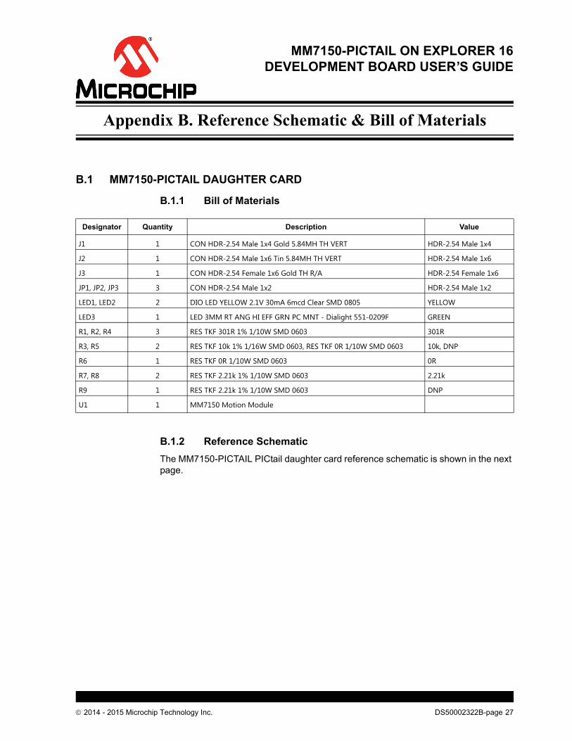
B.1 MM7150-PICTAIL DAUGHTER CARD
B.1.1 Bill of Materials
B.1.2 Reference Schematic
The MM7150-PICTAIL PICtail daughter card reference schematic is shown in the next page.
Designator Quantity Description Value
J1 1 CON HDR-2.54 Male 1x4 Gold 5.84MH TH VERT HDR-2.54 Male 1x4
J2 1 CON HDR-2.54 Male 1x6 Tin 5.84MH TH VERT HDR-2.54 Male 1x6
J3 1 CON HDR-2.54 Female 1x6 Gold TH R/A HDR-2.54 Female 1x6
JP1, JP2, JP3 3 CON HDR-2.54 Male 1x2 HDR-2.54 Male 1x2
LED1, LED2 2 DIO LED YELLOW 2.1V 30mA 6mcd Clear SMD 0805 YELLOW
LED3 1 LED 3MM RT ANG HI EFF GRN PC MNT - Dialight 551-0209F GREEN
R1, R2, R4 3 RES TKF 301R 1% 1/10W SMD 0603 301R
R3, R5 2 RES TKF 10k 1% 1/16W SMD 0603, RES TKF 0R 1/10W SMD 0603 10k, DNP
R6 1 RES TKF 0R 1/10W SMD 0603 0R
R7, R8 2 RES TKF 2.21k 1% 1/10W SMD 0603 2.21k
R9 1 RES TKF 2.21k 1% 1/10W SMD 0603 DNP
U1 1 MM7150 Motion Module
2014 - 2015 Microchip Technology Inc. DS50002322B-page 27

MM
71
50-P
ICT
AIL
Mo
tion
Mo
du
le P
ICta
il with
Ex
plo
rer 16
De
velo
pm
en
t Bo
ard
Us
er’s G
uid
e
DS
50002322B
-page 28
2014 - 2015 M
icrochip Technolo
gy Inc.

DS50002322B-page 29 2014 - 2015 Microchip Technology Inc.
AMERICASCorporate Office2355 West Chandler Blvd.Chandler, AZ 85224-6199Tel: 480-792-7200 Fax: 480-792-7277Technical Support: http://www.microchip.com/supportWeb Address: www.microchip.com
AtlantaDuluth, GA Tel: 678-957-9614 Fax: 678-957-1455
Austin, TXTel: 512-257-3370
BostonWestborough, MA Tel: 774-760-0087 Fax: 774-760-0088
ChicagoItasca, IL Tel: 630-285-0071 Fax: 630-285-0075
ClevelandIndependence, OH Tel: 216-447-0464 Fax: 216-447-0643
DallasAddison, TX Tel: 972-818-7423 Fax: 972-818-2924
DetroitNovi, MI Tel: 248-848-4000
Houston, TX Tel: 281-894-5983
IndianapolisNoblesville, IN Tel: 317-773-8323Fax: 317-773-5453
Los AngelesMission Viejo, CA Tel: 949-462-9523 Fax: 949-462-9608
New York, NY Tel: 631-435-6000
San Jose, CA Tel: 408-735-9110
Canada - TorontoTel: 905-673-0699 Fax: 905-673-6509
ASIA/PACIFICAsia Pacific OfficeSuites 3707-14, 37th FloorTower 6, The GatewayHarbour City, KowloonHong KongTel: 852-2943-5100Fax: 852-2401-3431
Australia - SydneyTel: 61-2-9868-6733Fax: 61-2-9868-6755
China - BeijingTel: 86-10-8569-7000 Fax: 86-10-8528-2104
China - ChengduTel: 86-28-8665-5511Fax: 86-28-8665-7889
China - ChongqingTel: 86-23-8980-9588Fax: 86-23-8980-9500
China - Dongguan
Tel: 86-769-8702-9880
China - HangzhouTel: 86-571-8792-8115 Fax: 86-571-8792-8116
China - Hong Kong SARTel: 852-2943-5100 Fax: 852-2401-3431
China - NanjingTel: 86-25-8473-2460Fax: 86-25-8473-2470
China - QingdaoTel: 86-532-8502-7355Fax: 86-532-8502-7205
China - ShanghaiTel: 86-21-5407-5533 Fax: 86-21-5407-5066
China - ShenyangTel: 86-24-2334-2829Fax: 86-24-2334-2393
China - ShenzhenTel: 86-755-8864-2200 Fax: 86-755-8203-1760
China - WuhanTel: 86-27-5980-5300Fax: 86-27-5980-5118
China - XianTel: 86-29-8833-7252Fax: 86-29-8833-7256
ASIA/PACIFICChina - XiamenTel: 86-592-2388138 Fax: 86-592-2388130
China - ZhuhaiTel: 86-756-3210040 Fax: 86-756-3210049
India - BangaloreTel: 91-80-3090-4444 Fax: 91-80-3090-4123
India - New DelhiTel: 91-11-4160-8631Fax: 91-11-4160-8632
India - PuneTel: 91-20-3019-1500
Japan - OsakaTel: 81-6-6152-7160 Fax: 81-6-6152-9310
Japan - TokyoTel: 81-3-6880- 3770 Fax: 81-3-6880-3771
Korea - DaeguTel: 82-53-744-4301Fax: 82-53-744-4302
Korea - SeoulTel: 82-2-554-7200Fax: 82-2-558-5932 or 82-2-558-5934
Malaysia - Kuala LumpurTel: 60-3-6201-9857Fax: 60-3-6201-9859
Malaysia - PenangTel: 60-4-227-8870Fax: 60-4-227-4068
Philippines - ManilaTel: 63-2-634-9065Fax: 63-2-634-9069
SingaporeTel: 65-6334-8870Fax: 65-6334-8850
Taiwan - Hsin ChuTel: 886-3-5778-366Fax: 886-3-5770-955
Taiwan - KaohsiungTel: 886-7-213-7828
Taiwan - TaipeiTel: 886-2-2508-8600 Fax: 886-2-2508-0102
Thailand - BangkokTel: 66-2-694-1351Fax: 66-2-694-1350
EUROPEAustria - WelsTel: 43-7242-2244-39Fax: 43-7242-2244-393Denmark - CopenhagenTel: 45-4450-2828 Fax: 45-4485-2829
France - ParisTel: 33-1-69-53-63-20 Fax: 33-1-69-30-90-79
Germany - DusseldorfTel: 49-2129-3766400
Germany - MunichTel: 49-89-627-144-0 Fax: 49-89-627-144-44
Germany - PforzheimTel: 49-7231-424750
Italy - Milan Tel: 39-0331-742611 Fax: 39-0331-466781
Italy - VeniceTel: 39-049-7625286
Netherlands - DrunenTel: 31-416-690399 Fax: 31-416-690340
Poland - WarsawTel: 48-22-3325737
Spain - MadridTel: 34-91-708-08-90Fax: 34-91-708-08-91
Sweden - StockholmTel: 46-8-5090-4654
UK - WokinghamTel: 44-118-921-5800Fax: 44-118-921-5820
Worldwide Sales and Service
01/27/15