mcp6sx2 pga thermistor pictail demo board user's...
TRANSCRIPT

© 2006 Microchip Technology Inc. DS51517B
MCP6SX2 PGA ThermistorPICtail™ Demo Board
User’s Guide

Note the following details of the code protection feature on Microchip devices:• Microchip products meet the specification contained in their particular Microchip Data Sheet.
• Microchip believes that its family of products is one of the most secure families of its kind on the market today, when used in the intended manner and under normal conditions.
• There are dishonest and possibly illegal methods used to breach the code protection feature. All of these methods, to our knowledge, require using the Microchip products in a manner outside the operating specifications contained in Microchip’s Data Sheets. Most likely, the person doing so is engaged in theft of intellectual property.
• Microchip is willing to work with the customer who is concerned about the integrity of their code.
• Neither Microchip nor any other semiconductor manufacturer can guarantee the security of their code. Code protection does not mean that we are guaranteeing the product as “unbreakable.”
Code protection is constantly evolving. We at Microchip are committed to continuously improving the code protection features of ourproducts. Attempts to break Microchip’s code protection feature may be a violation of the Digital Millennium Copyright Act. If such actsallow unauthorized access to your software or other copyrighted work, you may have a right to sue for relief under that Act.
Information contained in this publication regarding deviceapplications and the like is provided only for your convenienceand may be superseded by updates. It is your responsibility toensure that your application meets with your specifications.MICROCHIP MAKES NO REPRESENTATIONS ORWARRANTIES OF ANY KIND WHETHER EXPRESS ORIMPLIED, WRITTEN OR ORAL, STATUTORY OROTHERWISE, RELATED TO THE INFORMATION,INCLUDING BUT NOT LIMITED TO ITS CONDITION,QUALITY, PERFORMANCE, MERCHANTABILITY ORFITNESS FOR PURPOSE. Microchip disclaims all liabilityarising from this information and its use. Use of Microchipdevices in life support and/or safety applications is entirely atthe buyer’s risk, and the buyer agrees to defend, indemnify andhold harmless Microchip from any and all damages, claims,suits, or expenses resulting from such use. No licenses areconveyed, implicitly or otherwise, under any Microchipintellectual property rights.
DS51517B-page ii
Trademarks
The Microchip name and logo, the Microchip logo, Accuron, dsPIC, KEELOQ, microID, MPLAB, PIC, PICmicro, PICSTART, PRO MATE, PowerSmart, rfPIC and SmartShunt are registered trademarks of Microchip Technology Incorporated in the U.S.A. and other countries.
AmpLab, FilterLab, Migratable Memory, MXDEV, MXLAB, SEEVAL, SmartSensor and The Embedded Control Solutions Company are registered trademarks of Microchip Technology Incorporated in the U.S.A.
Analog-for-the-Digital Age, Application Maestro, dsPICDEM, dsPICDEM.net, dsPICworks, ECAN, ECONOMONITOR, FanSense, FlexROM, fuzzyLAB, In-Circuit Serial Programming, ICSP, ICEPIC, Linear Active Thermistor, Mindi, MiWi, MPASM, MPLIB, MPLINK, PICkit, PICDEM, PICDEM.net, PICLAB, PICtail, PowerCal, PowerInfo, PowerMate, PowerTool, REAL ICE, rfLAB, rfPICDEM, Select Mode, Smart Serial, SmartTel, Total Endurance, UNI/O, WiperLock and ZENA are trademarks of Microchip Technology Incorporated in the U.S.A. and other countries.
SQTP is a service mark of Microchip Technology Incorporated in the U.S.A.
All other trademarks mentioned herein are property of their respective companies.
© 2006, Microchip Technology Incorporated, Printed in the U.S.A., All Rights Reserved.
Printed on recycled paper.
© 2006 Microchip Technology Inc.
Microchip received ISO/TS-16949:2002 certification for its worldwide headquarters, design and wafer fabrication facilities in Chandler and Tempe, Arizona, Gresham, Oregon and Mountain View, California. The Company’s quality system processes and procedures are for its PICmicro® 8-bit MCUs, KEELOQ® code hopping devices, Serial EEPROMs, microperipherals, nonvolatile memory and analog products. In addition, Microchip’s quality system for the design and manufacture of development systems is ISO 9001:2000 certified.
MCP6SX2 PGA THERMISTOR PICtail™
DEMO BOARD USER’S GUIDETable of Contents
Preface ........................................................................................................................... 1Introduction............................................................................................................ 1Document Layout .................................................................................................. 1Conventions Used in this Guide ............................................................................ 2Recommended Reading........................................................................................ 3The Microchip Web Site ........................................................................................ 3Customer Support ................................................................................................. 4Document Revision History ................................................................................... 4
Chapter 1. Product Overview ....................................................................................... 51.1 Introduction ..................................................................................................... 51.2 What is thE MCP6SX2 PGA Thermistor PICtail™ Demo Board? .................. 51.3 What the MCP6SX2 PGA Thermistor PICtail™ Demo Board Kit Includes .... 51.4 Associated Tools ............................................................................................ 6
Chapter 2. Setup and Installation ................................................................................ 92.1 Introduction ..................................................................................................... 92.2 Required Tools ............................................................................................... 92.3 Connecting The MCP6SX2 PGA Thermistor PICtail™ Demo Board ............. 9
Chapter 3. Using the MCP6SX2 PGA Thermistor PICtail™ Demo Board ............... 113.1 Introduction ................................................................................................... 113.2 Configuring Board ........................................................................................ 11
Appendix A. Schematic and Layouts ........................................................................ 19A.1 Introduction .................................................................................................. 19A.2 Demonstration Board Description ................................................................ 19A.3 Additional Comments ................................................................................... 20A.4 Board Schematic ........................................................................................ 21A.5 Board - Top Silk-Screen And Metal Layers ................................................ 22A.6 Board - Top Metal Layer ............................................................................ 23A.7 Board - Bottom Metal Layer ...................................................................... 24
Appendix B. Bill Of Materials (BOM) ......................................................................... 25B.1 Components Installed on PCB ..................................................................... 25B.2 Separately Packaged Components ............................................................. 26
Worldwide Sales and Service .................................................................................... 28
© 2006 Microchip Technology Inc. DS51517B-page iii

MCP6SX2 PGA Thermistor PICtail™ Demo Board User’s Guide
NOTES:
DS51517B-page iv © 2006 Microchip Technology Inc.

MCP6SX2 PGA THERMISTOR PICtail™
DEMO BOARD USER’S GUIDEPreface
INTRODUCTIONThis chapter contains general information that will be useful to know before using the MCP6SX2 PGA Thermistor PICtail™ Demo Board. Items discussed in this chapter include:• Document Layout• Conventions Used in this Guide• Recommended Reading• The Microchip Web Site• Customer Support• Document Revision History
DOCUMENT LAYOUTThis document describes how to use the MCP6SX2 PGA Thermistor PICtail™ Demo Board as a development tool. The manual layout is as follows:• Chapter 1. “Product Overview” – An introduction to the MCP6SX2 PGA
Thermistor PICtail™ Demo Board. It covers the kit contents, associated tools and how they work together.
• Chapter 2. “Setup and Installation” – Covers the initial set-up of the MCP6SX2 PGA Thermistor PICtail™ Demo Board. It lists the required tools, shows how to connect this board and demonstates how to verify the set-up.
• Chapter 3. “Using the MCP6SX2 PGA Thermistor PICtail™ Demo Board” – Discusses different light sources, using the Signal Analysis PC application and setting up the board as a stand-alone.
• Appendix A. “Schematic and Layouts” – Gives detailed information on the MCP6SX2 PGA Thermistor PICtail™ Demo Board. Includes detailed circuit explanation, schematic and board layouts.
• Appendix B. “Bill Of Materials (BOM)” – List the parts used to build the MCP6SX2 PGA Thermistor PICtail™ Demo Board.
NOTICE TO CUSTOMERS
All documentation becomes dated, and this manual is no exception. Microchip tools and documentation are constantly evolving to meet customer needs, so some actual dialogs and/or tool descriptions may differ from those in this document. Please refer to our web site (www.microchip.com) to obtain the latest documentation available.
Documents are identified with a “DS” number. This number is located on the bottom of each page, in front of the page number. The numbering convention for the DS number is “DSXXXXXA”, where “XXXXX” is the document number and “A” is the revision level of the document.
© 2006 Microchip Technology Inc. DS51517B-page 1

MCP6SX2 PGA Thermistor PICtail™ Demo Board User’s Guide
CONVENTIONS USED IN THIS GUIDEThis manual uses the following documentation conventions:
DOCUMENTATION CONVENTIONSDescription Represents Examples
Arial font:Italic characters Referenced books MPLAB® IDE User’s Guide
Emphasized text ...is the only compiler...Initial caps A window the Output window
A dialog the Settings dialogA menu selection select Enable Programmer
Quotes A field name in a window or dialog
“Save project before build”
Underlined, italic text with right angle bracket
A menu path File>Save
Bold characters A dialog button Click OKA tab Click the Power tab
N‘Rnnnn A number in verilog format, where N is the total number of digits, R is the radix and n is a digit.
4‘b0010, 2‘hF1
Text in angle brackets < > A key on the keyboard Press <Enter>, <F1>Courier New font:Plain Courier New Sample source code #define START
Filenames autoexec.batFile paths c:\mcc18\h
Keywords _asm, _endasm, static
Command-line options -Opa+, -Opa-Bit values 0, 1
Constants 0xFF, ‘A’
Italic Courier New A variable argument file.o, where file can be any valid filename
Square brackets [ ] Optional arguments mcc18 [options] file [options]
Curly brackets and pipe character: { | }
Choice of mutually exclusive arguments; an OR selection
errorlevel {0|1}
Ellipses... Replaces repeated text var_name [, var_name...]
Represents code supplied by user
void main (void){ ...}
DS51517B-page 2 © 2006 Microchip Technology Inc.

Preface
RECOMMENDED READINGThis user's guide describes how to use the MCP6SX2 PGA Thermistor PICtail™ Demo Board. Other useful documents are listed below. The following Microchip documents are available and recommended as supplemental reference resources.PICkit™ 1 Flash Starter Kit User’s Guide (DS40051)Contains instructions on how to use the PICkit 1 Flash Starter Kit hardware and software.Signal Analysis PICtail™ Daughter Board User’s Guide (DS51476)Contains instructions on how to use the Signal Analysis PICtail™ Daughter Board’s hardware and software.AN897, “Thermistor Temperature Sensing with MCP6SX2 PGAs” (DS00897)Explains the functionality and design of this board’s circuit. Contains measurement results.MCP6S21/2/6/8 Data Sheet (DS21117)Gives detailed information on the MCP6S21/2/3/6/8 Programmable Gain Amplifiers (PGA).MCP6S91/2/3 Data Sheet (DS21908)Gives detailed information on the MCP6S91/2/3 PGAs.PIC16F684 Data Sheet (DS41202)Gives detailed information on the PICmicro microcontroller used on the Signal Analysis PICtail Daughter Board.PIC16C745/765 Data Sheet (DS41124)Gives detailed information on the PICmicro® microcontroller used on the PICkit 1 Flash Starter Kit.
THE MICROCHIP WEB SITEMicrochip provides online support via our web site at www.microchip.com. This web site is used as a means to make files and information easily available to customers. Accessible by using your favorite Internet browser, the web site contains the following information:• Product Support – Data sheets and errata, application notes and sample
programs, design resources, user’s guides and hardware support documents, latest software releases and archived software
• General Technical Support – Frequently Asked Questions (FAQs), technical support requests, online discussion groups, Microchip consultant program member listing
• Business of Microchip – Product selector and ordering guides, latest Microchip press releases, listing of seminars and events, listings of Microchip sales offices, distributors and factory representatives
© 2006 Microchip Technology Inc. DS51517B-page 3

MCP6SX2 PGA Thermistor PICtail™ Demo Board User’s Guide
CUSTOMER SUPPORTUsers of Microchip products can receive assistance through several channels:• Distributor or Representative• Local Sales Office• Field Application Engineer (FAE)• Technical Support• Development Systems Information LineCustomers should contact their distributor, representative or field application engineer for support. Local sales offices are also available to help customers. A listing of sales offices and locations is included in the back of this document.Technical support is available through the web site at: http://support.microchip.com
DOCUMENT REVISION HISTORY
Revision B (May 2006)• Updated Bill of Materials (BOM) to show RoHS-compliant part numbers.• Updated title of this document to match web site board name.
Revision A (October 2004)• Initial Release of this Document.
DS51517B-page 4 © 2006 Microchip Technology Inc.

MCP6SX2 PGA THERMISTOR PICtail™
DEMO BOARD USER’S GUIDEChapter 1. Product Overview
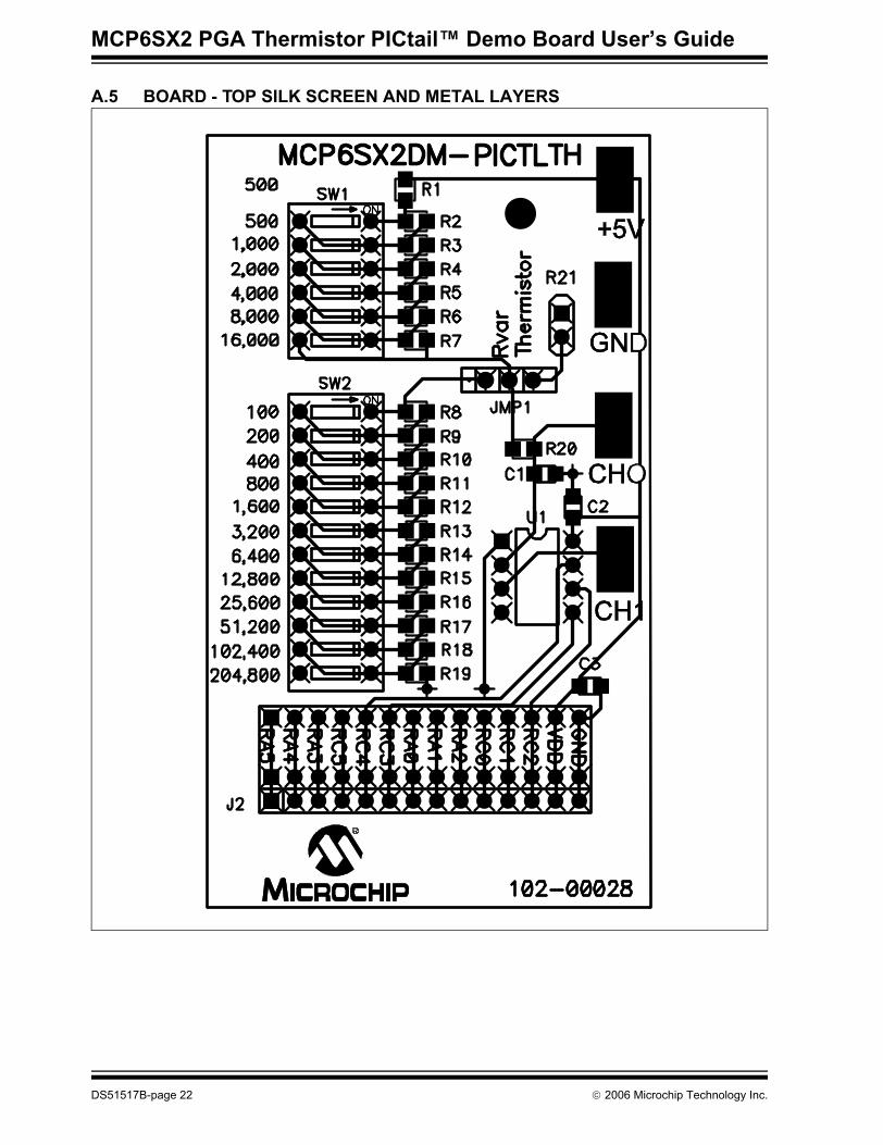
1.1 INTRODUCTIONThe following name and assembly number are found on the MCP6SX2 PGA Ther-mistor PICtail™ Demo Board’s Printed Circuit Board (PCB):• MCP6SX2DM-PICTLTH• 102-00028This PCB goes by the following title:• MCP6SX2 PGA Thermistor PICtail™ Demo BoardThis board is supported by AN897, “Thermistor Temperature-Sensing with MCP6SX2 PGAs”, (DS00897). It uses a BC Components® 2322 640 55103 NTC thermistor to detect temperature. The circuit also includes a voltage divider and a MCP6S22 Programmable Gain Amplifier (PGA).• Kit Contents• MCP6SX2 PGA Thermistor PICtail™ Demo Board• Associated Tools• Initial Set-up
1.2 WHAT IS THE MCP6SX2 PGA THERMISTOR PICTAIL™ DEMO BOARD?The MCP6SX2 PGA Thermistor PICtail™ Demo Board contains the analog circuitry represented in Figure 1-1. It uses BC Components’ 2322 640 55103 NTC thermistor to convert temperature to resistance. The thermistor is placed in a voltage divider which converts resistance to voltage. This voltage is filtered and placed at the MCP6S22 Programmable Gain Amplifier’s (PGA) CH0 input. The PGA gains and buffers this output, which is sent off board (VOUT). Board power is applied at the +5V and GND inputs. The SPI bus makes it possible to control the PGA; its gain and input channel can be set, as desired, from the software.
1.3 WHAT THE MCP6SX2 PGA THERMISTOR PICTAIL™ DEMO BOARD KIT INCLUDES
• MCP6SX2 PGA Thermistor PICtail™ Demo Board – An assembled and tested PCB (102-00028)
• PICkit™ 1 CD-ROM (DS40049) – Contains the files and literature mentioned in this user’s guide
• Stand-off, screw and an additional PGA (MCP6S92) provided in an anti-static bag
© 2006 Microchip Technology Inc. DS51517B-page 5

MCP6SX2 PGA Thermistor PICtail™ Demo Board User’s Guide
FIGURE 1-1: MCP6SX2 PGA Thermistor PICtail™ Demo Board Block Diagram.
The test points make it easier to test key points in the circuit, change the input signals, and to use this as a stand-alone board.• GND Test Point – Connected to the ground plane, it is a convenient ground point
for any lab equipment• +5V Test Point – Allows measurement of the positive supply voltage and provides
a means to power this board with a laboratory power supply• CH0 Test Point – The place to measure the voltage divider’s output (also the
PGA’s CH0 input)• CH1 Test Point – Makes it possible to send any desired signal to the PGAMore details on the circuit and its design can be found in Appendix A. “Schematic and Layouts” and in AN897 (DS00897).
1.4 ASSOCIATED TOOLSFigure 1-2 shows the block diagram of the hardware and software tools that the MCP6SX2 PGA Thermistor PICtail™ Demo Board is designed to work with. More infor-mation on these tools can be found in the “Recommended Reading” section.
FIGURE 1-2: Measurement Set-up Block Diagram.
Thermistor
CH1 Input
Thermistor
VoltageDivider
MCP6S22
MCP6SX2 PGA ThermistorPICtail™ Demo Board
VOUT
SPI™ Bus
4CH0 Input
+5V
GND GND+5V
Temperature
Test Point
Test Point
Test Point
Test Point
PGA
PC
USB
Signal AnalysisPICtail™ Daughter Board
PICkit™ 1Flash Starter Kit
14
MCP6SX2 PGA ThermistorPICtail™ Demo Board
PICkit™ 1 Signal AnalysisPC Program
14
PICkit™ 1Firmware
PICA2Dlab.hexFirmware
Hardware Software
DS51517B-page 6 © 2006 Microchip Technology Inc.

Product Overview
1.4.1 PC PlatformThe Personal Computer (PC) shown in Figure 1-2 needs to run on Windows® 98 SE or later. It provides a convenient interface for the user, communicates with the other boards and provides power through the USB connection.
1.4.2 PICkit™ 1 Signal Analysis PC ProgramThe PICkit™ 1 Signal Analysis PC program configures and programs the PIC16F684 PICmicro® microcontroller on the Signal Analysis PICtail Daughter Board through the USB port on the PICkit 1 Flash Starter Kit. It also imports data through the same connection and displays the data in strip-chart, histogram, FFT plot and oscilloscope plot formats. Data can be output in CSV format for importing into a spreadsheet program.
1.4.3 PICkit 1 Flash Starter KitThe PICkit 1 Flash Starter Kit (DV164101) programs PICmicro microcontrollers. It uses the PIC16C745’s USB port to communicate with the PICkit 1 Signal Analysis PC program. It connects to the Signal Analysis PICtail Daughter Board via a header (see Figure 2-1).This board provides a single +5V supply voltage for the daughter boards. It can drive up to 5 µF on the supply; a larger capacitance may interfere with program timing.
1.4.4 PICkit 1 FirmwareThis software resides on the PICkit 1 Flash Starter Kit’s PIC16C745 microcontroller. Use version 2.0.2 or later.
1.4.5 Signal Analysis PICtail Daughter BoardThis board is Microchip Development Tool AC164120. It connects to the PICkit 1 Flash Starter Kit, which it uses for both power and as a communications link to the PC. The on-board PIC16F684 has a 10-bit ADC which converts the MCP6SX2 PGA Thermistor PICtail™ Demo Board’s output voltage. The results are temporarily stored on the board’s 25LC640 serial EEPROM chips.The +5V single supply voltage from the PICkit 1 Flash Starter Kit board is bypassed with a bulk 1 µF capacitor and local 0.1 µF capacitors for each IC.
1.4.6 Firmware for the Signal Analysis PICtail Daughter BoardPICA2Dlab.hex is the standard file that supports the PICkit™ 1 Signal Analysis PC program. The PGA and 10-bit ADC configuration are selected in the Signal Analysis PC program and written to the PIC16F684. The PIC16F684 then sends the command(s) over the SPI™ bus to the PGA. It displays the ADC code on the strip chart.Therm_PGA1.hex implements the first design in AN897. It supports the PICkit™ 1 Signal Analysis PC program, but with reduced functionality; its output can be viewed on the strip chart only. The results need to be manually converted to commonly-seen temperature (codes 0 to 1023 convert to 0.0°C to 102.3°C).Therm_PGA2.hex implements the second design in AN897. It supports the PICkit™ 1 Signal Analysis PC program, but with reduced functionality; its output can be viewed on the strip chart only. The results need to be manually converted to commonly-seen temperature (codes 0 to 1023 convert to 0.0°C to 102.3°C).
© 2006 Microchip Technology Inc. DS51517B-page 7

MCP6SX2 PGA Thermistor PICtail™ Demo Board User’s Guide
1.4.7 Interface DetailsA more detailed look at how the MCP6SX2 PGA Thermistor PICtail™ Demo Board interfaces with the other boards is shown in Figure 1-3.
FIGURE 1-3: Detailed Interface Diagram.
Thermistor
VoltageDivider
PGAMCP6S22
MCP6SX2 PGA ThermistorPICtail™ Demo Board
VOUT
SPI Bus
4
SerialEEPROM
PIC16F684
ADC
Signal AnalysisPICtail™ Daughter Board
GND+5V
GND+5V
PICkit™ 1Flash Starter Kit
4
SPI™ Bus
CH1 Input
CH0 Input
+5V
GND
Test Point
Test Point
Test Point
Test Point
2PIC16F745
USBto PC
ThermistorTemperature
DS51517B-page 8 © 2006 Microchip Technology Inc.
MCP6SX2 PGA THERMISTOR PICtail™
DEMO BOARD USER’S GUIDEChapter 2. Setup and Installation
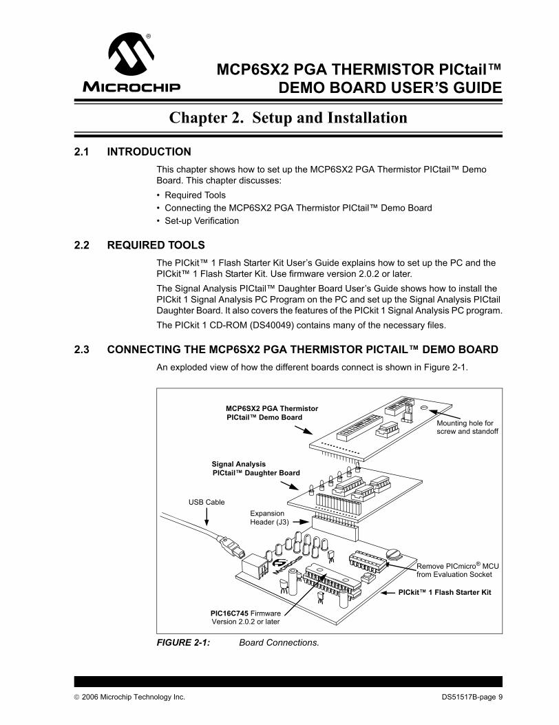
2.1 INTRODUCTIONThis chapter shows how to set up the MCP6SX2 PGA Thermistor PICtail™ Demo Board. This chapter discusses:• Required Tools• Connecting the MCP6SX2 PGA Thermistor PICtail™ Demo Board• Set-up Verification
2.2 REQUIRED TOOLSThe PICkit™ 1 Flash Starter Kit User’s Guide explains how to set up the PC and the PICkit™ 1 Flash Starter Kit. Use firmware version 2.0.2 or later.The Signal Analysis PICtail™ Daughter Board User’s Guide shows how to install the PICkit 1 Signal Analysis PC Program on the PC and set up the Signal Analysis PICtail Daughter Board. It also covers the features of the PICkit 1 Signal Analysis PC program.The PICkit 1 CD-ROM (DS40049) contains many of the necessary files.
2.3 CONNECTING THE MCP6SX2 PGA THERMISTOR PICTAIL™ DEMO BOARDAn exploded view of how the different boards connect is shown in Figure 2-1.
FIGURE 2-1: Board Connections.
Signal Analysis
PICkit™ 1 Flash Starter Kit
USB CableExpansionHeader (J3)
PICtail™ Daughter Board
Remove PICmicro® MCUfrom Evaluation Socket
PIC16C745 FirmwareVersion 2.0.2 or later
MCP6SX2 PGA Thermistor PICtail™ Demo Board
Mounting hole forscrew and standoff
© 2006 Microchip Technology Inc. DS51517B-page 9

MCP6SX2 PGA Thermistor PICtail™ Demo Board User’s Guide
2.3.1 PCB StandoffThe standoff and screw listed in Table B-2 are installed at the mounting hole shown in Figure 2-1. The standoff goes on bottom, and the screw on top.
2.3.2 PICkit 1 Flash Starter Kit1. Remove any PICmicro microcontroller that may be in the evaluation socket.2. Connect the USB cable to the PC and the PICkit 1 Flash Starter Kit board. The
status LEDs (green POWER and yellow BUSY in the LED array) should light up.It is easiest to use this board when it lays directly on a bench top.
2.3.3 Signal Analysis PICtail Daughter BoardThis board plugs into the PICkit 1 Flash Starter Kit’s expansion header J3 and must not cover the LED array. There should be no change in the status LEDs on the PICkit 1 Flash Starter Kit board after it is plugged in.
2.3.4 MCP6SX2 PGA Thermistor PICtail™ Demo BoardIf you would rather use the MCP6S92 PGA, take it out of the anti-static bag and replace the already installed MCP6S22 PGA. 1. Plug this board into, and directly above, the Signal Analysis PICtail Daughter
Board. There should be no change in the status LEDs on the PICkit 1 Flash Starter Kit board after it is plugged in.
2.3.4 Set-up Verification1. Select the Real Time Mode radio button.2. Click on the Strip Chart button.3. Change the sample speed to 20 Sample/Secs.4. Click on the green GO button; the strip chart will show the measured output of
the MCP6SX2 PGA Thermistor PICtail™ Demo Board.5. Change the switch positions (SW1 and SW2) and verify that the strip chart
changes. Figure 2-2 shows the result when RA was set to 10 kΩ and Rvar to 0Ω, then 12.8 kΩ, and then 217.6 kΩ (see Section 3.2 “Configuring Board”).
FIGURE 2-2: Strip Chart.
DS51517B-page 10 © 2006 Microchip Technology Inc.

MCP6SX2 PGA THERMISTOR PICtail™
DEMO BOARD USER’S GUIDEChapter 3. Using the MCP6SX2 PGA Thermistor PICtail™ Demo Board
3.1 INTRODUCTIONThis demonstration board makes it easy to explore the operation of two thermistor applications using the MCP6S22 PGA. Items discussed in this chapter include:• Configuring the Board• Using the Signal Analysis PC Program for This Board• Stand-Alone Board Set-up
3.2 CONFIGURING BOARD
3.2.1 Configuring Jumper JMP1 (select Thermistor or Rvar)Figure 3-1 shows how jumper JMP1 configures the circuit. When the shorting bar is on the right side of jumper JMP1, the thermistor RTH is connected to the circuit. When it is on the left side of jumper JMP1, the thermistor emulator Rvar is connected to the circuit.Refer to Figure A.4 for the complete schematic.
FIGURE 3-1: Simplified Jumper Circuit.
Rva
r
Ther
mis
tor
Rvar RTH
JMP1
VDD = 5.0V
RA
To filter and PGA’s CH0 input
© 2006 Microchip Technology Inc. Draft DS51517B-page 11

MCP6SX2 PGA Thermistor PICtail™ Demo Board User’s Guide
3.2.2 Configuring DIP Switch SW1 (RA)DIP switch SW1 and resistors R1 – R7 in Figure 3-2 emulate the voltage divider resistor (RA in Figure 3-1). R1 is placed in series with the others to prevent shorting the supplies together. These resistors produce a binary sequence of values between 0.5 kΩ and 32.0 kΩ.Refer to Figure A.4 for the complete schematic.
FIGURE 3-2: RA Emulator.
Each resistor with its switch (in SW1) pointing to the right, away from the silk screen resistor values, is not added into the total for RA (it shorts that resistor). Each resistor with its switch (in SW1) pointing to the left, towards the silk screen resistor values, is added into the total for RA. As an example, if the top four switches are to the right, and the bottom two are to the left, then RA is calculated as 500 + 0 + 0 + 0 + 0 + 8,000 + 16,000 = 24,500Ω.
3.2.3 Using the Thermistor (RTH)R21 in Section A.4 “Board Schematic” is the thermistor (RTH in Figure 3-1). The resistance changes depending on temperature; see AN897, “Thermistor Temperature Sensing with MCP6SX2 PGAs” (DS00897).
5001,0002,0004,0008,000
16,000
R1499
+5V
SW1
R2 499ΩR3 1.00 kΩR4 2.00 kΩR5 4.02 kΩR6 8.06 kΩR7 16.0 kΩ
500
DS51517B-page 12 Draft © 2006 Microchip Technology Inc.

Using the MCP6SX2 PGA Thermistor PICtail™ Demo Board
3.2.4 Configuring DIP Switch SW2 (RTH Emulator, Rvar)DIP switch SW2 and resistors R8 – R19 in Figure 3-3 comprise the thermistor emulator (Rvar in Figure 3-1). Rvar produces a binary sequence of resistances between 0Ω and 409.5 kΩ.Refer to Figure A.4 for the complete schematic.
FIGURE 3-3: RTH Emulator (Rvar).
Each resistor with its switch (in SW2) pointing to the right, away from the silk screen resistor values, is not added into the total for RA (it shorts that resistor). Each resistor with its switch (in SW2) pointing to the left, towards the silk screen resistor values, is added into the total for RA. As an example, if the top ten switches are to the right, and the bottom two are to the left, then Rvar is calculated as 0 + 0 + ... + 0 + 102,400 + 204,800 = 307,200Ω.AN897, “Thermistor Temperature Sensing with MCP6SX2 PGAs” (DS00897) contains information on converting this resistance to the equivalent, nominal thermistor temperature, and visa-versa.
3.2.5 Using the Signal Analysis PC Application for This BoardSee “Chapter 2. Using the PICkit™ Signal Analysis PC Application” of the “Signal Analysis PICtail™ Daughter Board User’s Guide” (DS51476) for details on displaying measured results. The possible formats include: oscilloscope, FFT, histogram and strip-chart.The measured results can then be interpreted as temperature; see AN897, “Thermistor Temperature Sensing with MCP6SX2 PGAs” (DS00897).
100200400800
1,6003,2006,400
12,80025,60051,200
102,400204,800
SW2
R8 100ΩR9 200ΩR10 402ΩR11 806ΩR12 1.6 kΩR13 3.24 kΩR14 6.49 kΩR15 12.7 kΩR16 25.5 kΩR17 51.1 kΩR18 102 kΩR19 205 kΩ
© 2006 Microchip Technology Inc. Draft DS51517B-page 13

MCP6SX2 PGA Thermistor PICtail™ Demo Board User’s Guide
3.2.6 Choosing Firmware for the Signal Analysis PICtail Daughter Board
Use the standard PICA2Dlab.hex file to measure and analyze the PGA’s output voltage. This file supports all of the display functionality of the PICkit 1 Signal Analysis PC application program.Use Therm_PGA1.hex to implement the first design shown in AN897, “Thermistor Temperature Sensing with MCP6SX2 PGAs” (DS00897). Its output can only be viewed on the strip chart. The results need to be manually converted to commonly-seen temperatures (codes 0 to 1023 convert to 0.0°C to 102.3°C).Use Therm_PGA2.hex to implement the second design in AN897, “Thermistor Temperature Sensing with MCP6SX2 PGAs” (DS00897). Its output can only be viewed on the strip chart. The results need to be manually converted to commonly-seen temperatures (codes 0 to 1023 convert to 0.0°C to 102.3°C).
DS51517B-page 14 Draft © 2006 Microchip Technology Inc.

Using the MCP6SX2 PGA Thermistor PICtail™ Demo Board
3.2.7 Configure the PGAThe PICkit 1 Signal Analysis PC program can configure the PGA; see Figure 3-4. The MCP6S22 PGA defaults to a gain of 1 and CH0.
1. Open the PGA window by clicking the External Devices button.2. Select the correct PGA from the indicated pull-down list.3. Select the desired PGA input. Usually the selection will be CH0 for the thermistor
output, but it can be CH1 when another input source is provided at the CH1 test point (Figure 1-1).a. Select Write to Register from the indicated pull-down list. (Figure 3-4, #5)b. Set A0 = 1. (Figure 3-4, #6)c. Set C2:C0 to all zeros. (Figure 3-4, #7)d. Execute the command by clicking on the Write to PGA button. (Figure 3-4,
#8)4. Select the desired PGA gain.
a. Select Write to Register from the indicated pull-down list. (Figure 3-4, #5)b. Set A0 = 0. (Figure 3-4, #6)c. Select PGA gain from the pull-down list. (Figure 3-4, #4))d. Execute the command by clicking on the Write to PGA button.
(Figure 3-4, #8)
FIGURE 3-4: PGA Configuration.
Note: The MCP6S92 PGA powers up to a random state; it must have its gain and input written to it before it will operate as expected.
1. Open PGA Window2. Select PGA3. Select Channel
4. Select Gain5. Select Operation 6. Set Register Pointer
7. Set Input Channel
8. Execute
© 2006 Microchip Technology Inc. Draft DS51517B-page 15
MCP6SX2 PGA Thermistor PICtail™ Demo Board User’s Guide
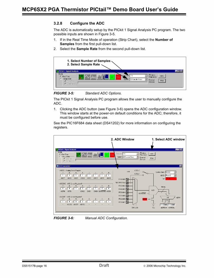
3.2.8 Configure the ADCThe ADC is automatically setup by the PICkit 1 Signal Analysis PC program. The two possible inputs are shown in Figure 3-5.1. If in the Real Time Mode of operation (Strip Chart), select the Number of
Samples from the first pull-down list.2. Select the Sample Rate from the second pull-down list.
FIGURE 3-5: Standard ADC Options.
The PICkit 1 Signal Analysis PC program allows the user to manually configure the ADC.1. Clicking the ADC button (see Figure 3-6) opens the ADC configuration window.
This window starts at the power-on default conditions for the ADC; therefore, it must be configured before use.
See the PIC16F684 data sheet (DS41202) for more information on configuring the registers.
FIGURE 3-6: Manual ADC Configuration.
1. Select Number of Samples2. Select Sample Rate
1. Select ADC window2. ADC Window
DS51517B-page 16 Draft © 2006 Microchip Technology Inc.
Using the MCP6SX2 PGA Thermistor PICtail™ Demo Board
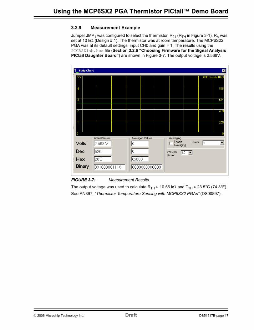
3.2.9 Measurement ExampleJumper JMP1 was configured to select the thermistor, R21 (RTH in Figure 3-1). RA was set at 10 kΩ (Design # 1). The thermistor was at room temperature. The MCP6S22 PGA was at its default settings, input CH0 and gain = 1. The results using the PICA2Dlab.hex file (Section 3.2.6 “Choosing Firmware for the Signal Analysis PICtail Daughter Board”) are shown in Figure 3-7. The output voltage is 2.568V.
FIGURE 3-7: Measurement Results.
The output voltage was used to calculate RTH ≈ 10.56 kΩ and TTH ≈ 23.5°C (74.3°F).See AN897, “Thermistor Temperature Sensing with MCP6SX2 PGAs” (DS00897).
© 2006 Microchip Technology Inc. Draft DS51517B-page 17
MCP6SX2 PGA Thermistor PICtail™ Demo Board User’s Guide
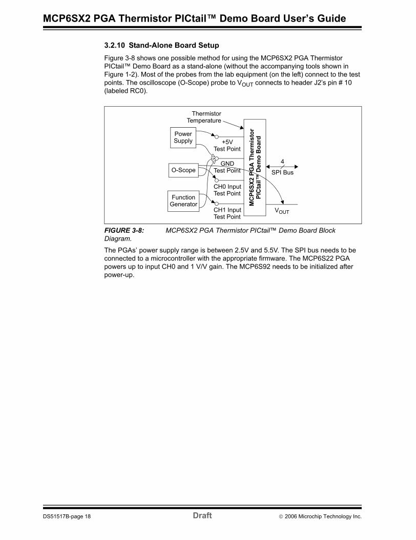
3.2.10 Stand-Alone Board SetupFigure 3-8 shows one possible method for using the MCP6SX2 PGA Thermistor PICtail™ Demo Board as a stand-alone (without the accompanying tools shown in Figure 1-2). Most of the probes from the lab equipment (on the left) connect to the test points. The oscilloscope (O-Scope) probe to VOUT connects to header J2’s pin # 10 (labeled RC0).
FIGURE 3-8: MCP6SX2 PGA Thermistor PICtail™ Demo Board Block Diagram.
The PGAs’ power supply range is between 2.5V and 5.5V. The SPI bus needs to be connected to a microcontroller with the appropriate firmware. The MCP6S22 PGA powers up to input CH0 and 1 V/V gain. The MCP6S92 needs to be initialized after power-up.
CH1 Input
MC
P6SX
2 PG
A T
herm
isto
rPI
Cta
il™ D
emo
Boa
rd
SPI Bus
4
CH0 Input
+5V
GND
Test Point
Test Point
Test Point
Test Point
PowerSupply
FunctionGenerator
O-Scope
VOUT
ThermistorTemperature
DS51517B-page 18 Draft © 2006 Microchip Technology Inc.

MCP6SX2 PGA THERMISTOR PICtail™
DEMO BOARD USER’S GUIDEAppendix A. Schematic and Layouts
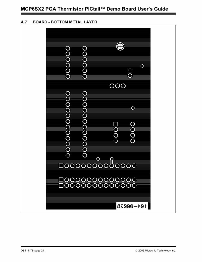
A.1 INTRODUCTIONThis appendix contains the schematics and layouts for the MCP6SX2 PGA Thermistor PICtail™ Demo Board.The MCP6SX2-PICTLTH demonstration board is constructed using a two-layer Printed Circuit Board (PCB). The top layer is for components and traces, while the bottom layer is the ground plane.Information on this board includes:• Board Schematic• Board - Top Silk-Screen And Metal Layers• Board - Top Metal Layer• Board - Bottom Metal Layer
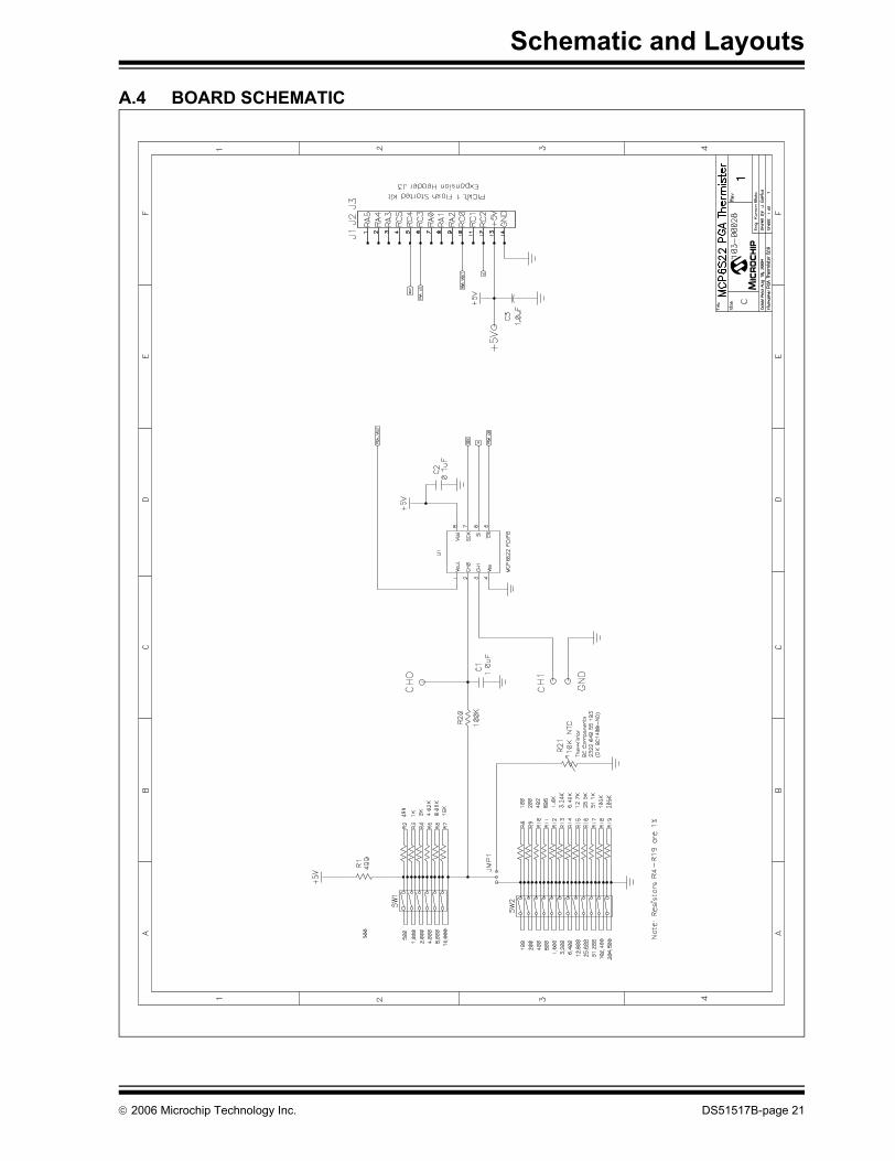
A.2 DEMONSTRATION BOARD DESCRIPTIONA simplified block diagram of this board is shown in Figure 1-1. The detailed schematic is given in Figure A.4. DIP switch SW1 and resistors R1 – R7 emulate the voltage divider’s series resistor (RA in Figure 3-1). R1 is placed in series with the others to prevent shorting the supplies together. Resistors R1 – R7 produce a binary sequence of values between 0.5 kΩ and 32.0 kΩ.R21 is the thermistor (RTH in Figure 3-1). DIP switch SW2 and resistors R8 – R19 (labeled Rvar in top silk screen) emulate the thermistor. Rvar produces a binary sequence between 0Ω and 409.5 kΩ. The jumper JMP1 selects either the thermistor or its emulator Rvar. R20 and C1 are the low-pass analog filters used to minimize noise. They also act as anti-aliasing filters for the ADC.U1 is either the MCP6S22 or the MCP6S92 Programmable Gain Amplifier (PGA). The PGA buffers the transimpedance amplifier output and makes it possible to gain up weak signals before conversion by the ADC. J2 connects this board to the Signal Analysis board. C2 and C3 are bypass capacitors that minimize power supply noise.The demonstration board includes test points for convenience on the bench. The +5V and GND test points connect to the board’s supply voltages. The CH0 test point connects to the PGA’s CH0 input; it is also connected to the voltage divider’s output (with filtering). The CH1 test point allows the user to place any desired signal at the PGA’s CH1 input.
Note: While headers J1, J2, and J3 are shown together in the schematic (see Figure A.4), J2 is installed (see Table B-1), while J1 and J3 are not. J2 and J3 are placeholders only.
© 2006 Microchip Technology Inc. DS51517B-page 19

MCP6SX2 PGA Thermistor PICtail™ Demo Board User’s Guide
A.3 ADDITIONAL COMMENTSThe demonstration board includes test points for convenience on the bench. The +5V and GND test points connect to the board’s supply voltages. The CH0 test point connects to the PGA’s CH0 input; it is also connected to the voltage divider’s output (with filtering). The CH1 test point allows the user to place any desired signal at the PGA’s CH1 input.The PIC16F684 (and 10-bit ADC) are not part of the demo board schematic; see Figure 1-3 instead.The PICkit 1 Flash Starter Kit provides a +5V single supply voltage. It can drive up to 5 µF on the supply; a larger capacitive load causes current loading and timing issues.The PICkit 1 Flash Starter Kit Signal Analysis PICtail Daughter Board uses the +5V single supply voltage. It has 0.1 µF local bypass capacitors for each IC, and a 1 µF bulk bypass capacitor for the entire board.This demonstration board also uses the +5V single supply voltage. It has a 0.1 µF local bypass capacitor for the PGA, and a 1 µF bulk bypass capacitor for the entire board. A solid ground plane provides a good ground for the PGA.High-frequency design practices are used to minimize digital interference:• Solid ground plane• Surface-mount devices• Separate digital and analog lines and sections• Straight and short lines to the PGA
DS51517B-page 20 © 2006 Microchip Technology Inc.
Schematic and Layouts
A.4 BOARD SCHEMATIC
M
© 2006 Microchip Technology Inc. DS51517B-page 21
MCP6SX2 PGA Thermistor PICtail™ Demo Board User’s Guide
A.5 BOARD - TOP SILK SCREEN AND METAL LAYERS
DS51517B-page 22 © 2006 Microchip Technology Inc.

Schematic and Layouts
A.6 BOARD - TOP METAL LAYER
© 2006 Microchip Technology Inc. DS51517B-page 23
MCP6SX2 PGA Thermistor PICtail™ Demo Board User’s Guide
A.7 BOARD - BOTTOM METAL LAYER
DS51517B-page 24 © 2006 Microchip Technology Inc.
MCP6SX2 PGA THERMISTOR PICtail™
DEMO BOARD USER’S GUIDEAppendix B. Bill Of Materials (BOM)
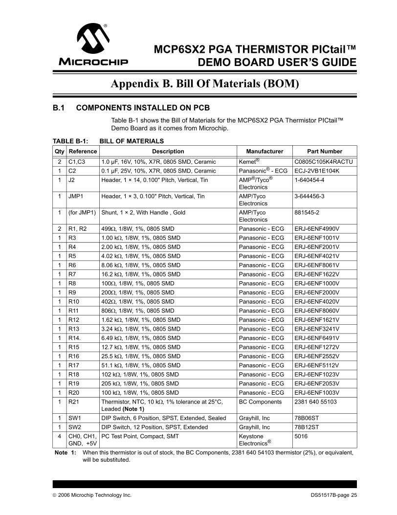
B.1 COMPONENTS INSTALLED ON PCBTable B-1 shows the Bill of Materials for the MCP6SX2 PGA Thermistor PICtail™ Demo Board as it comes from Microchip.
TABLE B-1: BILL OF MATERIALSQty Reference Description Manufacturer Part Number
2 C1,C3 1.0 µF, 16V, 10%, X7R, 0805 SMD, Ceramic Kemet® C0805C105K4RACTU1 C2 0.1 µF, 25V, 10%, X7R, 0805 SMD, Ceramic Panasonic® - ECG ECJ-2VB1E104K1 J2 Header, 1 × 14, 0.100" Pitch, Vertical, Tin AMP®/Tyco®
Electronics1-640454-4
1 JMP1 Header, 1 × 3, 0.100" Pitch, Vertical, Tin AMP/TycoElectronics
3-644456-3
1 (for JMP1) Shunt, 1 × 2, With Handle , Gold AMP/TycoElectronics
881545-2
2 R1, R2 499Ω, 1/8W, 1%, 0805 SMD Panasonic - ECG ERJ-6ENF4990V1 R3 1.00 kΩ, 1/8W, 1%, 0805 SMD Panasonic - ECG ERJ-6ENF1001V1 R4 2.00 kΩ, 1/8W, 1%, 0805 SMD Panasonic - ECG ERJ-6ENF2001V1 R5 4.02 kΩ, 1/8W, 1%, 0805 SMD Panasonic - ECG ERJ-6ENF4021V1 R6 8.06 kΩ, 1/8W, 1%, 0805 SMD Panasonic - ECG ERJ-6ENF8061V1 R7 16.2 kΩ, 1/8W, 1%, 0805 SMD Panasonic - ECG ERJ-6ENF1622V1 R8 100Ω, 1/8W, 1%, 0805 SMD Panasonic - ECG ERJ-6ENF1000V1 R9 200Ω, 1/8W, 1%, 0805 SMD Panasonic - ECG ERJ-6ENF2000V1 R10 402Ω, 1/8W, 1%, 0805 SMD Panasonic - ECG ERJ-6ENF4020V1 R11 806Ω, 1/8W, 1%, 0805 SMD Panasonic - ECG ERJ-6ENF8060V1 R12 1.62 kΩ, 1/8W, 1%, 0805 SMD Panasonic - ECG ERJ-6ENF1621V1 R13 3.24 kΩ, 1/8W, 1%, 0805 SMD Panasonic - ECG ERJ-6ENF3241V1 R14. 6.49 kΩ, 1/8W, 1%, 0805 SMD Panasonic - ECG ERJ-6ENF6491V1 R15 12.7 kΩ, 1/8W, 1%, 0805 SMD Panasonic - ECG ERJ-6ENF1272V1 R16 25.5 kΩ, 1/8W, 1%, 0805 SMD Panasonic - ECG ERJ-6ENF2552V1 R17 51.1 kΩ, 1/8W, 1%, 0805 SMD Panasonic - ECG ERJ-6ENF5112V1 R18 102 kΩ, 1/8W, 1%, 0805 SMD Panasonic - ECG ERJ-6ENF1023V1 R19 205 kΩ, 1/8W, 1%, 0805 SMD Panasonic - ECG ERJ-6ENF2053V1 R20 100 kΩ, 1/8W, 1%, 0805 SMD Panasonic - ECG ERJ-6ENF1003V1 R21 Thermistor, NTC, 10 kΩ, 1% tolerance at 25°C,
Leaded (Note 1)BC Components 2381 640 55103
1 SW1 DIP Switch, 6 Position, SPST, Extended, Sealed Grayhill, Inc 78B06ST1 SW2 DIP Switch, 12 Position, SPST, Extended Grayhill, Inc 78B12ST4 CH0, CH1,
GND, +5VPC Test Point, Compact, SMT Keystone
Electronics®5016
Note 1: When this thermistor is out of stock, the BC Components, 2381 640 54103 thermistor (2%), or equivalent, will be substituted.
© 2006 Microchip Technology Inc. DS51517B-page 25

MCP6SX2 PGA Thermistor PICtail™ Demo Board User’s Guide
B.2 SEPARATELY PACKAGED COMPONENTSTable B-2 lists the components that are packaged separately in an anti-static bag.
1 U1 MCP6S22, PGA, 10 MHz, 2 inputs, PDIP-8 Microchip Technology Inc.
MCP6S22-I/P
1 (for U1) IC Socket, 8-pin DIP, Tin, 0.300" AMP/TycoElectronics
2-641260-1
1 PCB Lead Free RoHS Compliant PCB — 104-000280 J1, J3 Not Populated — —
TABLE B-1: BILL OF MATERIALS (CONTINUED)Qty Reference Description Manufacturer Part Number
Note 1: When this thermistor is out of stock, the BC Components, 2381 640 54103 thermistor (2%), or equivalent, will be substituted.
TABLE B-2: BILL OF MATERIALS – SEPARATELY PACKAGED COMPONENTSQty Reference Description Manufacturer Part Number
1 U1 MCP6S92, PGA, 10 MHz, 2 inputs, PDIP-8 (Note 1) Microchip Technology Inc.
MCP6S92-E/P
1 — Nylon Standoff, Hex, 1.000", 4-40 Thread (Note 2) KeystoneElectronics®
1902E
1 — Phillips Machine Screw, 3/8", 4-40 Thread (Note 2) Building Fasteners
NY PMS 440 0038 PH
Note 1: Section 2.3.4 “MCP6SX2 PGA Thermistor PICtail™ Demo Board” andSection 3.2.7 “Configure the PGA” discuss installing and using this PGA.
2: Section 2.3.1 “PCB Standoff” describes the installation of these parts.
DS51517B-page 26 © 2006 Microchip Technology Inc.

Bill Of Materials (BOM)
NOTES:
© 2006 Microchip Technology Inc. DS51517B-page 27

DS51517B-page 28 © 2006 Microchip Technology Inc.
AMERICASCorporate Office2355 West Chandler Blvd.Chandler, AZ 85224-6199Tel: 480-792-7200 Fax: 480-792-7277Technical Support: http://support.microchip.comWeb Address: www.microchip.comAtlantaAlpharetta, GA Tel: 770-640-0034 Fax: 770-640-0307BostonWestborough, MA Tel: 774-760-0087 Fax: 774-760-0088ChicagoItasca, IL Tel: 630-285-0071 Fax: 630-285-0075DallasAddison, TX Tel: 972-818-7423 Fax: 972-818-2924DetroitFarmington Hills, MI Tel: 248-538-2250Fax: 248-538-2260KokomoKokomo, IN Tel: 765-864-8360Fax: 765-864-8387Los AngelesMission Viejo, CA Tel: 949-462-9523 Fax: 949-462-9608San JoseMountain View, CA Tel: 650-215-1444Fax: 650-961-0286TorontoMississauga, Ontario, CanadaTel: 905-673-0699 Fax: 905-673-6509
ASIA/PACIFICAustralia - SydneyTel: 61-2-9868-6733 Fax: 61-2-9868-6755China - BeijingTel: 86-10-8528-2100 Fax: 86-10-8528-2104China - ChengduTel: 86-28-8676-6200 Fax: 86-28-8676-6599China - FuzhouTel: 86-591-8750-3506 Fax: 86-591-8750-3521China - Hong Kong SARTel: 852-2401-1200 Fax: 852-2401-3431China - QingdaoTel: 86-532-8502-7355Fax: 86-532-8502-7205China - ShanghaiTel: 86-21-5407-5533 Fax: 86-21-5407-5066China - ShenyangTel: 86-24-2334-2829Fax: 86-24-2334-2393China - ShenzhenTel: 86-755-8203-2660 Fax: 86-755-8203-1760China - ShundeTel: 86-757-2839-5507 Fax: 86-757-2839-5571China - WuhanTel: 86-27-5980-5300Fax: 86-27-5980-5118China - XianTel: 86-29-8833-7250Fax: 86-29-8833-7256
ASIA/PACIFICIndia - BangaloreTel: 91-80-4182-8400 Fax: 91-80-4182-8422India - New DelhiTel: 91-11-5160-8631Fax: 91-11-5160-8632India - PuneTel: 91-20-2566-1512Fax: 91-20-2566-1513Japan - YokohamaTel: 81-45-471- 6166 Fax: 81-45-471-6122Korea - GumiTel: 82-54-473-4301Fax: 82-54-473-4302Korea - SeoulTel: 82-2-554-7200Fax: 82-2-558-5932 or 82-2-558-5934Malaysia - PenangTel: 60-4-646-8870Fax: 60-4-646-5086Philippines - ManilaTel: 63-2-634-9065Fax: 63-2-634-9069SingaporeTel: 65-6334-8870Fax: 65-6334-8850Taiwan - Hsin ChuTel: 886-3-572-9526Fax: 886-3-572-6459Taiwan - KaohsiungTel: 886-7-536-4818Fax: 886-7-536-4803Taiwan - TaipeiTel: 886-2-2500-6610 Fax: 886-2-2508-0102Thailand - BangkokTel: 66-2-694-1351Fax: 66-2-694-1350
EUROPEAustria - WelsTel: 43-7242-2244-399Fax: 43-7242-2244-393Denmark - CopenhagenTel: 45-4450-2828 Fax: 45-4485-2829France - ParisTel: 33-1-69-53-63-20 Fax: 33-1-69-30-90-79Germany - MunichTel: 49-89-627-144-0 Fax: 49-89-627-144-44Italy - Milan Tel: 39-0331-742611 Fax: 39-0331-466781Netherlands - DrunenTel: 31-416-690399 Fax: 31-416-690340Spain - MadridTel: 34-91-708-08-90Fax: 34-91-708-08-91UK - WokinghamTel: 44-118-921-5869Fax: 44-118-921-5820
WORLDWIDE SALES AND SERVICE
02/16/06