short report on physical quantities to be measured in laboratory
TRANSCRIPT

Measurement of LuminousCharacteristics of Daylighting
Materials
A Report of IEA SHCP TASK 21 / ECBCS ANNEX29September 1999
International Energy Agency
Energy Conservation inBuildings and Community
Systems Programme
IEA SHC TASK 21 / ECBCS ANNEX 29, Measurement of Luminous Characteristics
I
Distribution Classification: Unrestricted
This report was printed and is available at:
Institut für Elektronik und LichttechnikTechnischen Universität BerlinSekr.: E6Einsteinufer 1910587 Berlin, Germany
Fax: +49-30-314 22161 T21/A4-10/GER/99-11
IEA SHC TASK 21 / ECBCS ANNEX 29, Measurement of Luminous Characteristics
II
Measurement of LuminousCharacteristics of DaylightingMaterials
International Energy Agency (IEA)Solar Heating and Cooling Programme Task 21 /
Energy Conservation in Buildings and CommunitySystems Programme Annex 29:
DAYLIGHT IN BUILDINGS
Sirri Aydinli, Heinrich KaaseInstitute of Electronics and LightingTechnologyTechnical University of BerlinSekr.: E6Einsteinufer 1910587 Berlin
IEA SHC TASK 21 / ECBCS ANNEX 29, Measurement of Luminous Characteristics Preface
III
PREFACE
The main objectives of the IEA Solar Heating and Cooling Programme (SHC) Task 21and the Energy Conservation in Buildings and Community Systems Programme(ECBCS) Annex 29 "Daylight in Buildings" are to advance daylighting technologies andto promote daylight conscious building design. Since Task 21 is finished, it willendeavour to overcome the barriers that are impending the appropriate integration ofdaylighting aspects in building design. The participants in this task are Australia,Austria, Belgium, Canada, Denmark, Finland, France, Germany, Italy, Netherlands,New Zealand, Norway, Sweden, Switzerland, United Kingdom and the United States.Denmark is the Operating Agent.
The main objective of Subtask A “Performance Evaluation of Daylighting Systems” is toprovide a Design Guide for building designer on the selection and appropriateintegration of daylighting systems and strategies in new and renovated buildings. Theresulting Design Guide will document the performance of the system tested, giveinformation on system construction and maintenance, and recommendations onappropriate application of the different daylighting strategies under various climaticconditions. Subtask A is devided into 7 Subgroups:
A1: Survey of SystemsA2: Testing ProceduresA3: Pilot StudiesA4: Measurement of Physical CharacteristicsA5: Test Room StudiesA6: Scale Model StudiesA7: Source Book
This report “Measurement of Physical Characteristics” was initiated and compiled withinSubgroup A4.
IEA SHC TASK 21 / ECBCS ANNEX 29, Measurement of Luminous Characteristics Executive Summary
IV
EXECUTIVE SUMMARY
The document presents work conducted as part of Subtask A “Performance Evaluationof Daylighting Systems”, Subgroup A4, “Measurement of Physical Characteristics”, ofthe IEA SHC Task 21 and the ECBCS Program Annex 29 “Daylighting in Buildings”.
The planned use of daylight in buildings is nowadays a necessary strategy to minimisethe energy for lighting, heating and cooling as well as to improve the comfort and visualperformance in interiors. The use of daylight to replace or supplement electric lighting inbuildings can result in significant energy savings. New innovative daylighting systemsdeveloped over the last fifteen years are used to control the daylighting in interiors, thesolar radiation entering the interior as well as thermal losses and gains. For a gooddaylighting design in different climatic zones, the performance parameters of the useddaylighting system have to be known.
The aim of the project is to measure the luminous quantities of daylighting componentssuch as light transmittance and bi-directional transmittance distribution function (BTDF).The obtained data leads to the assessment of the capability of systems to utilisedaylight. Subtask C will be provided with the necessary data for the development ofalgorithms to predict energy saving in buildings.
For this, the appropriate measuring facilities of the three different institutions areidentified by carrying out the pilot measurements as well as analysing the possible errorsources of the measurements. The measurements for selected daylighting componentsare carried out. The corresponding data stored in the agreed data format is enclosed ona CD that comes with this report.
IEA SHC TASK 21 / ECBCS ANNEX 29, Measurement of Luminous Characteristics Contents
V
CONTENTS
1 INTRODUCTION ..................................................................................................... 1
2 DEFINITIONS OF THE CHARACTERISTICS AND MEASUREMENTPRINCIPLES .......................................................................................................... 3
2.1 Definitions .................................................................................................. 32.1.1 Transmittance .............................................................................................. 32.1.2 Regular Transmittance ................................................................................. 32.1.3 Diffuse Transmittance .................................................................................. 42.1.4 Luminance Factor ........................................................................................ 42.1.5 Luminance Coefficient
2.2 Parameters Affecting the Characteristics ................................................ 42.2.1 Spectral Parameters .................................................................................... 42.2.2 Geometric Conditions ................................................................................... 52.2.3 Other Parameters ......................................................................................... 6
2.3 Measurement Principles ............................................................................ 62.3.1 Absolute and Relative Methods ................................................................... 62.3.2 Spectral and Integral Characteristics ........................................................... 62.3.3 Spatial Evaluation ........................................................................................ 7
2.4 Measuring Facilities ................................................................................... 72.4.1 Goniophotometers ........................................................................................ 72.4.2 Sphere Photometers .................................................................................... 7
2.5 Measurement of Transmittance τ .............................................................. 72.5.1 Measurement with Sphere Photometer ........................................................ 72.5.2 Measurement of τ as a Function of Light Incidence ..................................... 82.5.3 Measurement of τ dif ...................................................................................... 8
2.6 Bi-directional Transmittance Distribution Function (BTDF) ................... 9
2.7 Spectral Measurement ............................................................................... 92.7.1 In Visible Wavelength Range ....................................................................... 92.7.2 In Solar Radiation Wavelength range (300 nm – 2500 nm) ......................... 9
2.8 Radiant and Thermal Properties .............................................................. 9
3 MEASUREMENTS ..................................................................................................10
3.1 Geometrical Description ............................................................................10
IEA SHC TASK 21 / ECBCS ANNEX 29, Measurement of Luminous Characteristics Contents
VI
4 LIGHT TRANSMITTANCE (DIRECTIONAL) MEASUREMENTS ...........................11
4.1 Short Description of the Measuring Facilities .........................................114.1.1 EPFL ............................................................................................................114.1.2 ISE ............................................................................................................... 124.1.3 TUB ..............................................................................................................13
4.2 Pilot Measurements ................................................................................... 154.2.1 Comparison of Measuring Results ...............................................................154.2.2 Analysis of the Error Sources ...................................................................... 17
4.3 Light Transmittance Measurement of Daylighting Systems ................. 184.3.1 Data Format ................................................................................................ 184.3.2 Presentation of Measurement Results ........................................................ 19
Laser Cut PanelPrismatic Film on GlassPrismatic PanelSun-directing GlassPlexiglas
4.3.3 Light transmittance for Hemispherical Light Incidence ................................ 22
5 BI-DIRECTIONAL MEASUREMENTS .................................................................. 23
5.1 Short Description of the Measuring Facilities ........................................ 235.1.1 EPFL ........................................................................................................... 235.1.2 ISE .............................................................................................................. 255.1.3 TUB ............................................................................................................. 26
5.2 Pilot Measurements .................................................................................. 285.2.1 Comparison of Measuring Results .............................................................. 285.2.2 Analysis of the Error Sources ...................................................................... 34
5.3 Bi-directional Measurement of Daylighting Systems ............................. 345.3.1 Light Incidence and Data Format ................................................................ 345.3.2 Presentation of Measurement Results ........................................................ 38
Prismatic Film on GlassSun-Directing GlassPlexiglas
6 REFERENCES .......................................................................................................43
7 LIST OF CONTACT PERSONS .............................................................................44
8 IEA INFORMATION ............................................................................................... 50
IEA SHC TASK 21 / ECBCS ANNEX 29, Measurement of Luminous Characteristics Symbols
VII
SYMBOLS
D 65 CIE standard illuminant to represent daylight
E Illuminance on a medium (lx = lm/m2)
f1 V(λ) match
f2 Cosine response
g Total solar energy transmittance (solar factor)
L Luminance of a surface element (cd/m2)
L(ϕ2, ε2) Luminance of a surface element in the direction of the viewing
(angles ϕ2 and θ2) (cd/m2)
Lw Luminance of a perfect reflecting or transmitting diffuser (cd/m2)
qi Secondary internal heat transfer factor
Ra General color rendering index
Ri Special color rendering indices (i = 1 ......... 14)
S(λ) Spectral power distribution of the radiation
s (λ)rel Relative spectral responsivity of a detector
Tcp Correlated color temperature (K)
U Thermal transmittance coefficient (W.m-2.K-1)
V(λ) Spectral luminous efficiency
φ Incident luminous flux (lm)
φτ Transmitted luminous flux (lm)
φτ r Regularly transmitted luminous flux (lm)
φτ d Diffusely transmitted luminous flux (lm)
β(ϕ2,θ2) Luminance factor in the direction of the viewing (angles ϕ2 and θ2)
q(ϕ2,θ2) Luminance coefficient in the direction of the viewing (angles ϕ2 and θ2)
τ Transmittance
τ (ϕ1,θ1) Transmittance for given light incidence (angles ϕ1 and θ1)
τ r Regular Transmittance
τ d Diffuse Transmittance
IEA SHC TASK 21 / ECBCS ANNEX 29, Measurement of Luminous Characteristics Symbols
VIII
τ dif Transmittance for hemispherical irradiation (diffuse incidence of radiation)
τ (D 65) Transmittance for CIE standard illuminant D 65
τ e Solar transmittance
ϕ1 Azimuth angle for light incidence
θ1 Elevation angle for light incidence, measured from the normal to the surface
ϕ2 Azimuth angle for viewing
θ2 Elevation angle for viewing, measured from the normal to the surface
IEA SHC TASK 21 / ECBCS ANNEX 29, Measurement of Luminous Characteristics Introduction
1
1 INTRODUCTION
The designed daylight utilisation in buildings is today very important to minimise theenergy for lighting, heating and cooling as well as to improve the comfort and visualperformance in buildings. The use of daylight to replace or supplement electric lightingin buildings can result in significant energy savings. New innovative daylighting systemsdeveloped over the last fifteen years are used to control the daylighting in interiors, thesolar radiation entering the interior as well as thermal losses and gains.
Many problems in daylighting design for different climatic zones can nowadays betreated and solved with simulation software. For this, the performance parameters ofthe used daylighting system have to be known sufficiently.
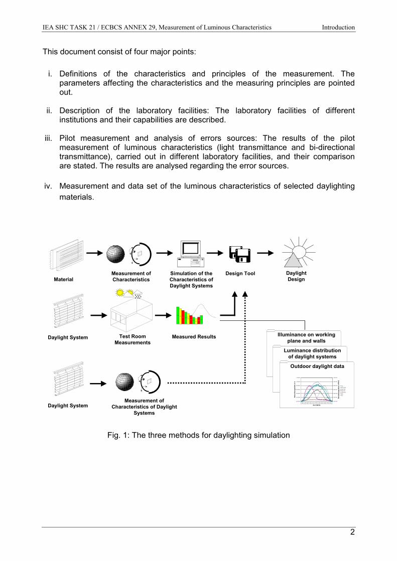
Daylighting design in interiors with design tools can be carried out in three differentways (fig. 1). The methods differ from each other by the availability of the data of thedaylighting system:
• The first possibility is the measurement of the luminous and radiant quantities of thedaylighting material or particular elements of the daylighting system in dependenceof light incidence. From this data, the corresponding quantities of the daylightingsystem can be determined by the computer simulation. The disadvantage of thisway is the urge of a lot of simulation steps and the lack of the availability ofcorresponding data of the daylighting materials.
• The second possibility is the measurement of the radiant and luminous quantities ofthe whole daylighting system. The data can directly be used in design tools. Theadvantage of this way is less simulation steps in comparison with the first method.The disadvantage is the limitation of the measuring facilities especially for themovable daylighting systems.
• The third possibility is to test of the daylighting systems in test rooms under differentsky conditions and in various seasons and at different daytimes. The advantage ofthis method is that the test of the corresponding daylighting system takes placeunder real conditions. The disadvantage is the extension of the test over a longtime.
The aim of the project is to measure the luminous quantities of daylighting materialsand components such as light transmittance and bi-directional transmittance distributionfunction (BTDF). The obtained data leads to the assessment of the capability ofsystems to utilise daylight. Subtask C will be provided with the necessary data for thedevelopment of algorithms to predict energy saving in buildings.
IEA SHC TASK 21 / ECBCS ANNEX 29, Measurement of Luminous Characteristics Introduction
2
This document consist of four major points:
i. Definitions of the characteristics and principles of the measurement. Theparameters affecting the characteristics and the measuring principles are pointedout.
ii. Description of the laboratory facilities: The laboratory facilities of differentinstitutions and their capabilities are described.
iii. Pilot measurement and analysis of errors sources: The results of the pilotmeasurement of luminous characteristics (light transmittance and bi-directionaltransmittance), carried out in different laboratory facilities, and their comparisonare stated. The results are analysed regarding the error sources.
iv. Measurement and data set of the luminous characteristics of selected daylightingmaterials.
Simulation of theCharacteristics ofDaylight Systems
Design Tool DaylightDesign
Measurement ofCharacteristicsMaterial
Test RoomMeasurements
Daylight System
0,00 E+00
2,00 E+04
4,00 E+04
6,00 E+04
8,00 E+04
1,00 E+05
1,20 E+05
03:3
504
:25
05:1
506
:05
06:5
507
:45
08:3
5
09:2
510
:15
11:0
511
:55
12:4
5
13:3
514
:25
15:1
516
:05
16:5
5
17:4
518
:35
19:2
5
20:1
5
Zeit (WOZ)
Bel
euch
tung
sstä
rke
in lx
0,00E+00
2,00E+02
4,00E+02
6,00E+02
8,00E+02
1,00E+03
1,20E+03
Best
rahl
ungs
stär
ke in
W/m
2
EvgEvg_West
Evg_SüdEvg_OstEvg_NordEegEes
Measured Results
100%90%
80%70%
60%50%
30%40% 40%
50%
Illuminance on workingplane and walls
Luminance distributionof daylight systems
Outdoor daylight data
Daylight SystemMeasurement of
Characteristics of DaylightSystems
Fig. 1: The three methods for daylighting simulation
IEA SHC TASK 21 / ECBCS ANNEX 29, Measurement of Luminous Characteristics Definitions
3
2 DEFINITIONS OF THE CHARACTERISTICS AND MEASUREMENTPRINCIPLES
The characteristics of materials are defined with respect to the International LightingVocabulary [1] and the relevant CIE publications : “Radiometric and PhotometricCharacteristics of Materials and their Measurement“ [2], “Absolute Methods forReflection Measurements“ [3], “A Review of Publications on Properties and ReflectionValues of Material Reflection Standards“ [4], and “ Practical Methods for theMeasurement of Reflectance and Transmittance“ [5].
2.1 Definitions
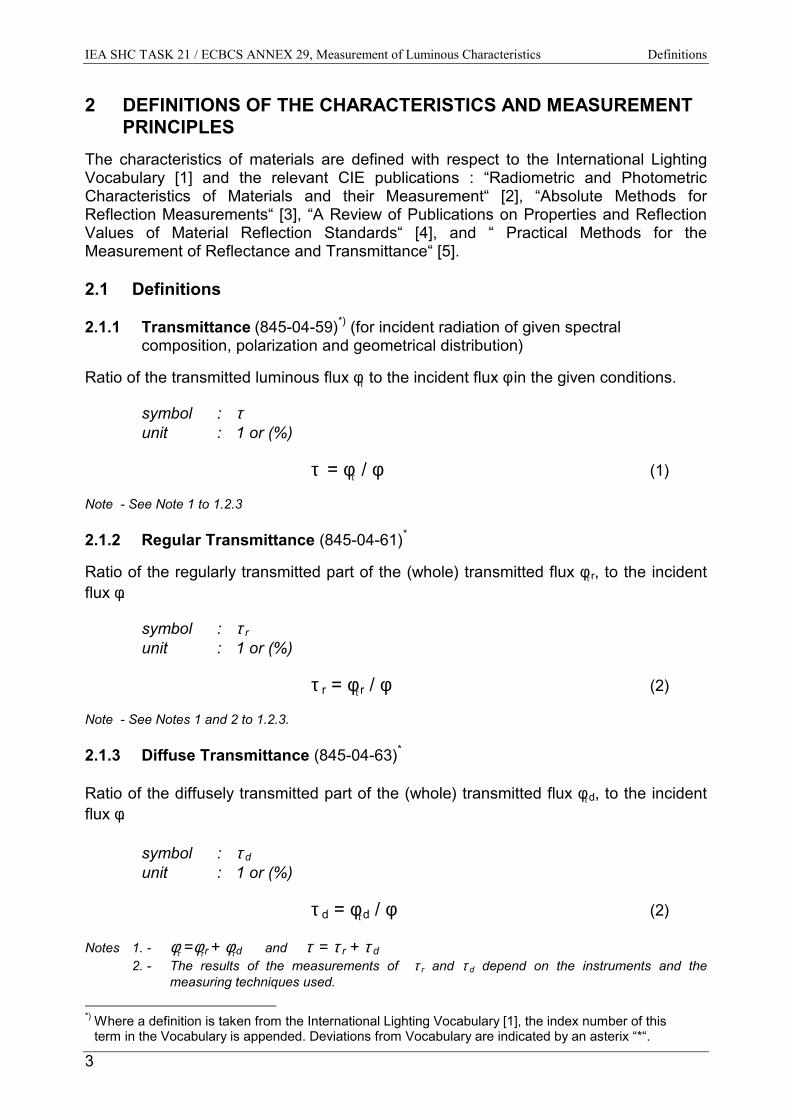
2.1.1 Transmittance (845-04-59)*) (for incident radiation of given spectral composition, polarization and geometrical distribution)
Ratio of the transmitted luminous flux φτ to the incident flux φ in the given conditions.
symbol : τunit : 1 or (%)
τ = φτ / φ (1)
Note - See Note 1 to 1.2.3
2.1.2 Regular Transmittance (845-04-61)*
Ratio of the regularly transmitted part of the (whole) transmitted flux φτ r, to the incidentflux φ.
symbol : τ runit : 1 or (%)
τ r = φτ r / φ (2)
Note - See Notes 1 and 2 to 1.2.3.
2.1.3 Diffuse Transmittance (845-04-63)*
Ratio of the diffusely transmitted part of the (whole) transmitted flux φτ d, to the incidentflux φ.
symbol : τ dunit : 1 or (%)
τ d = φτ d / φ (2)
Notes 1. - φτ =φτ r + φτ d and τ = τ r + τ d 2. - The results of the measurements of τ r and τ d depend on the instruments and the
measuring techniques used.
*) Where a definition is taken from the International Lighting Vocabulary [1], the index number of this
term in the Vocabulary is appended. Deviations from Vocabulary are indicated by an asterix “*“.
IEA SHC TASK 21 / ECBCS ANNEX 29, Measurement of Luminous Characteristics Definitions
4
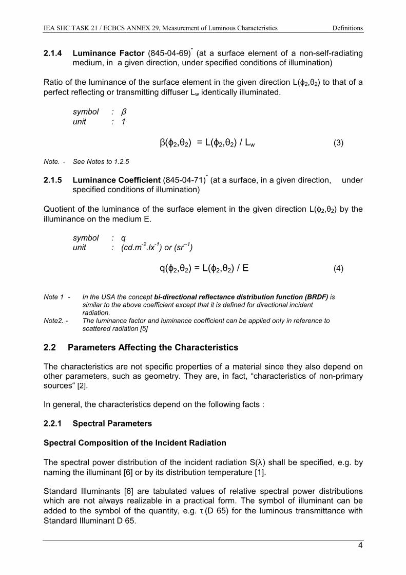
2.1.4 Luminance Factor (845-04-69)* (at a surface element of a non-self-radiatingmedium, in a given direction, under specified conditions of illumination)
Ratio of the luminance of the surface element in the given direction L(ϕ2,θ2) to that of aperfect reflecting or transmitting diffuser Lw identically illuminated.
symbol : βunit : 1
β(ϕ2,θ2) = L(ϕ2,θ2) / Lw (3)
Note. - See Notes to 1.2.5
2.1.5 Luminance Coefficient (845-04-71)* (at a surface, in a given direction, underspecified conditions of illumination)
Quotient of the luminance of the surface element in the given direction L(ϕ2,θ2) by theilluminance on the medium E.
symbol : qunit : (cd.m-2.lx-1) or (sr--1)
q(ϕ2,θ2) = L(ϕ2,θ2) / E (4)
Note 1 - In the USA the concept bi-directional reflectance distribution function (BRDF) is similar to the above coefficient except that it is defined for directional incident radiation.
Note2. - The luminance factor and luminance coefficient can be applied only in reference to scattered radiation [5]
2.2 Parameters Affecting the Characteristics
The characteristics are not specific properties of a material since they also depend onother parameters, such as geometry. They are, in fact, “characteristics of non-primarysources“ [2].
In general, the characteristics depend on the following facts :
2.2.1 Spectral Parameters
Spectral Composition of the Incident Radiation
The spectral power distribution of the incident radiation S(λ) shall be specified, e.g. bynaming the illuminant [6] or by its distribution temperature [1].
Standard Illuminants [6] are tabulated values of relative spectral power distributionswhich are not always realizable in a practical form. The symbol of illuminant can beadded to the symbol of the quantity, e.g. τ (D 65) for the luminous transmittance withStandard Illuminant D 65.
IEA SHC TASK 21 / ECBCS ANNEX 29, Measurement of Luminous Characteristics Definitions
5
Relative Spectral Responsivity of the Detector
The value of the characteristic to be measured depends strongly on the relative spectralresponsivity [7] s(λ)rel of the detector used for the measurement. A photometriccharacteristic could be preceded by the adjective “luminous“, e.g. luminoustransmittance, and obtained by s(λ)rel = V(λ).
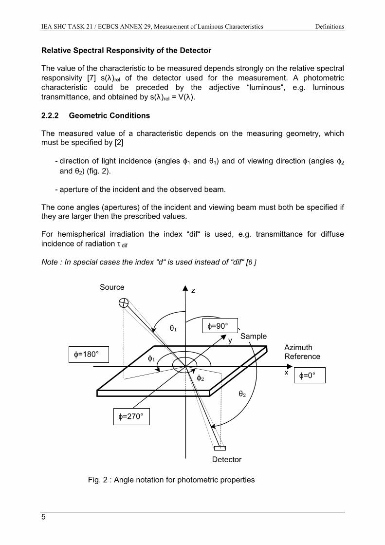
2.2.2 Geometric Conditions
The measured value of a characteristic depends on the measuring geometry, whichmust be specified by [2]
- direction of light incidence (angles ϕ1 and θ1) and of viewing direction (angles ϕ2
and θ2) (fig. 2).
- aperture of the incident and the observed beam.
The cone angles (apertures) of the incident and viewing beam must both be specified ifthey are larger then the prescribed values.
For hemispherical irradiation the index “dif“ is used, e.g. transmittance for diffuseincidence of radiation τ dif
Note : In special cases the index “d“ is used instead of “dif“ [6 ]
Fig. 2 : Angle notation for photometric properties
z
x
y
ϕ2
ϕ1
Source
Detector
AzimuthReference
θ1
θ2
Sample
ϕ=0°
ϕ=90°
ϕ=180°
ϕ=270°

IEA SHC TASK 21 / ECBCS ANNEX 29, Measurement of Luminous Characteristics Definitions
6
2.2.3 Other Parameters
Some other parameters are influencing the measured value of a specified characteristic[2]:
- The state of polarization of the radiation.If a characteristic is not determined with non-polarized radiation, the state ofpolarization and the azimuth of the plane of polarization must be specified. Thereflected or transmitted radiation is usually partly polarized even if the incidentradiation is non-polarized.
- The sample’s thickness.If necessary, the thickness of the sample must be given. For tinted or coatedmaterials the type and thickness of the coating must be given.
- The temperature.Characteristics are normally given for an ambient temperature of 25° C, if no othertemperature is specified.
- State of the surface.Characteristics are normally given for a clean and dry sample, if nothing else isspecified.
2.3 Measurement Principles
2.3.1 Absolute and Relative Methods
Since they are defined as the ratio of two fluxes, reflectance and transmittanceare, in themselves, relative characteristics, but, whenever their values aremeasured directly without the use of another material standard as a reference,the corresponding method is termed “absolute”.
Diffuse reflectance measurements are generally carried out with the help of astandard and are accordingly classified as relative methods. Absolute methodsdo exist [3], but they are normally restricted to standards laboratories, where they areused to make accurate calibrations of standards.
2.3.2 Spectral and Integral Characteristics
Spectral Method
With the spectral method, the relevant spectral characteristic, e.g. τ (λ) is measured asa function of the wavelength using as narrow a bandwidth as possible.
Integral Method
With the integral method the relevant weighted characteristic is measured directly,using a source having the prescribed spectral power distribution S(λ) and a detectorwith the required relative spectral weighting function, e.g. V(λ) for luminouscharacteristics and Standard illuminant A.
IEA SHC TASK 21 / ECBCS ANNEX 29, Measurement of Luminous Characteristics Definitions
7
2.3.3 Spatial Evaluation
Characteristics with hemispherical or conical incidence or collection of radiation can bemeasured using:
- Goniophotometers- Integrating sphere photometers- Directional methods
2.4 Measuring Facilities
Characteristics dependent light incidence and observation of radiation can bemeasured with :
- Goniophotometers
- Integrating sphere photometers
2.4.1 Goniophotometers
With goniophotometric measurements the radiation transmitted by the sample intodifferent directions is measured in these directions. If necessary, the angular data canthen be mathematically integrated (e.g. to yield the transmitted luminous flux).
2.4.2 Sphere Photometers
In sphere photometers the radiation transmitted by the sample into all directions iscollected and spatially integrated by the sphere.
2.5 Measurement of Transmittance τ
Generally these measurements are carried out with integrating sphere photometers.The measurements with a goniophotometer are often time consuming, expensive andmust be made by experienced persons.
2.5.1 Measurement with Sphere Photometer
According to the theory of Ulbricht, the luminous flux, transmitted by a sample is directlyproportional to the indirect illuminance on the inner surface of the integrating sphere.The luminous flux transmitted by a sample as well as the incident luminous flux on thesample can be measured with a photometer equipped with an integrating sphere, bycomparison to the flux of a standard.
The sample is positioned at a special sphere port. The direct irradiation of theacceptance area of the photometer head by transmitted radiation must be avoided by ascreen.
The coating for the inside of the sphere should reflect sufficiently diffuse and non-selective and must be uniform over the sphere’s surface. For the measurement ofluminous characteristics it is recommended to choose a coating with a reflectance ofabout 0.8 [8].
IEA SHC TASK 21 / ECBCS ANNEX 29, Measurement of Luminous Characteristics Definitions
8
For practical reasons, the sphere diameter should be as small as possible, but as largeas necessary. It is recommended to use a sphere with a diameter D ofD ≥ 10 times the sample port diameter.
Measurements with an integrating sphere with a large sample port (compared to thesphere diameter as above) can be made only according to the substitution method.This method tries to eliminate the influence of the changed average sphere reflectance(by different reflectance of sample and standard). It requires the so-called “auxiliaryscreen (lamp) measurement“.
In case of thick transmitting samples (particularly diffusing and with a structuredsurface), the transmitted flux may not entirely enter the sphere due to internalrefractions and scattering. The illuminated sample area must be smaller than thesample port area. Therefore, particularly large sample ports are often required,resorting to the substitution method and large sphere diameters. A sphere diameterD ≥ 0.5 m is recommended especially for the measurement of thick transmittingsamples.
2.5.2 Measurement of τ as a Function of Light Incidence
For the measurements of τ (ϕ1,θ1) as a function of the angles of incidence, theequipment for irradiation must either be turned around the center in the outside plane ofthe sample, or the integrating sphere must be turned around a vertical axis at thesample surface on the sample port (change of θ1 angle). Additionally, the sample mustbe turned around a horizontal (perpendicular to the sample’s surface) axis (change ofϕ1 angle).
2.5.3 Measurement of τ dif
For the measurement of the transmittance (τ dif) of hemispherical irradiation, theirradiation equipment consists of a hemisphere (or a sphere) by which the sample isirradiated by a nearly uniform luminance from the hemisphere.
The transmittance (τ dif) of hemispherical irradiation can be also calculated from themeasured function of τ (ϕ1,θ1).
11
2/
0111
2
0 11
2sin),(21 ϕθθθϕτπ
τπ
θ
π
ϕ
dddif ⋅⋅⋅= ∫∫==
(5)
For samples that are isotropic with respect to the azimuth of the incident radiation, τ isindependent of ϕ1. In this case, the double integral in equal (5) is simplified to the singleintegral:
1
2/
011
1
2sin)( θθθττπ
θ
ddif ⋅⋅= ∫=
(6)
IEA SHC TASK 21 / ECBCS ANNEX 29, Measurement of Luminous Characteristics Definitions
9
2.6 Bi-directional Transmittance Distribution Function (BTDF)
The BTDF is defined as the spatial distribution of luminance L(ϕ2,θ2) (luminance factorβ(ϕ2,θ2) or luminance coefficient q(ϕ2,θ2)) dependent on the angles of viewing angles ϕ2
and θ2 for given light incidence (angles ϕ1, and θ1).
These measurements can only be applied in reference to scattered radiation andcarried out with goniophotometers (described in [9, 10, 11]).
From the measured values of BTDF (luminance coefficient q(ϕ2,θ2)), the lighttransmittance τ (ϕ1,θ1) for given light incidents (ϕ1, and θ1) can be calculated :
22
2/
0222
2
011
22
2sin),(21),( ϕθθθϕθϕτ
π
θ
π
ϕ
ddq ⋅⋅⋅= ∫∫==
(7)
2.7 Spectral Measurements
2.7.1 In Visible Wavelength Range
For a selective transmittance (e.g. sun protecting glazing), this spectral measurementcan be necessary to determine the color and color rendering properties of daylight inthe interior. These are the correlated color temperature Tcp and CIE 1974 general colorrendering index Ra and special color rendering indices Ri of the light transmitted by thedaylight system for illumination by standard illuminant D 65 [6]
2.7.2 In Solar Radiation Wavelength Range (300 nm - 2500 nm)
With these measurements, the total energy transmittance g at a known thermaltransmittance coefficient (U-value) can be determined [12].
2.8 Radiant and Thermal Properties
The radiant and thermal situation in the interior is strongly influenced by the radiant andthermal characteristics of daylighting systems. These are
• Solar (radiant) transmittance τ e • Thermal transmittance coefficient (U-value)• Secondary internal heat transfer factor qi • Total solar energy transmittance (solar factor) g = τ e + qi
For the determination of the properties of these glazings, there are different standardmethods of calorimetric measurements and calculations [12,13]. In principle, thesemethods can also be used for daylighting systems.
IEA SHC TASK 21 / ECBCS ANNEX 29, Measurements of Luminous Characteristics Measurements
10
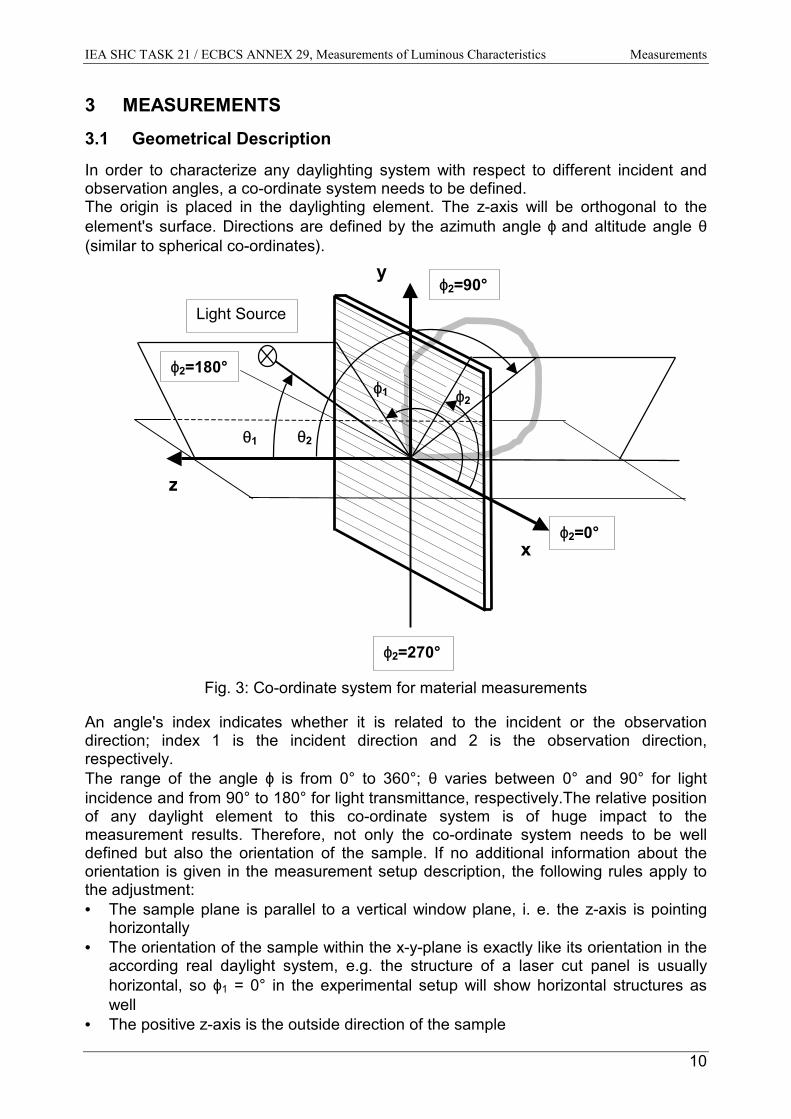
3 MEASUREMENTS3.1 Geometrical Description
In order to characterize any daylighting system with respect to different incident andobservation angles, a co-ordinate system needs to be defined.The origin is placed in the daylighting element. The z-axis will be orthogonal to theelement's surface. Directions are defined by the azimuth angle ϕ and altitude angle θ(similar to spherical co-ordinates).
Fig. 3: Co-ordinate system for material measurements
An angle's index indicates whether it is related to the incident or the observationdirection; index 1 is the incident direction and 2 is the observation direction,respectively.The range of the angle ϕ is from 0° to 360°; θ varies between 0° and 90° for lightincidence and from 90° to 180° for light transmittance, respectively.The relative positionof any daylight element to this co-ordinate system is of huge impact to themeasurement results. Therefore, not only the co-ordinate system needs to be welldefined but also the orientation of the sample. If no additional information about theorientation is given in the measurement setup description, the following rules apply tothe adjustment:• The sample plane is parallel to a vertical window plane, i. e. the z-axis is pointing
horizontally• The orientation of the sample within the x-y-plane is exactly like its orientation in the
according real daylight system, e.g. the structure of a laser cut panel is usuallyhorizontal, so ϕ1 = 0° in the experimental setup will show horizontal structures aswell
• The positive z-axis is the outside direction of the sample
ϕ2
θ2
x
ϕ1
ϕ2=0°
ϕ2=90°
ϕ2=270°
Light Source
z
y
ϕ2=180°
θ1

IEA SHC TASK 21 / ECBCS ANNEX 29, Measurement of Luminous Characteristics Light Transmittance
11
4 LIGHT TRANSMITTANCE (DIRECTIONAL) MEASUREMENTS
For the measurement of selected daylighting systems’ transmittance dependent on thelight incidence, the following measuring facilities of different institutes are available.
4.1 Short Description of the Measuring Facilities
4.1.1 Description of the Ulbricht Integrating Sphere for Measurement ofHemispherical Transmittance of Glazing Systems (EPFL)
LocationSolar Energy and Building Physics Laboratory (LESO-PB)Swiss Federal Institute of Technology (EPFL)
Integrating sphere Diameter : 1.5 m.Swiveling 180° on a horizontal axis (angle ε or θ ),passing through the sphere at the centerPlaced on a movable mechanical support (rolling wheels), allowing the choice ofdifferent azimuth angles (angle ϕ) White diffusive paint inside (ρ = 0,8)
Sample holderMaximal aperture diameter 30 cm, adjustable to 5, 10, 15, 20 and 25 cmMaximal size of glazing samples for holder: 40 cm
PhotometerKrochmann mini sensor, sensitive area: ∅ 6 mmPlaced at 90° angle of opening with an in-between bafflef1' Photopic correction : 2%; f2 cosine response : 1,5%
Transmittance values Light beam incidence : θ - angle from 0 to 90° (5° steps)ϕ – angle from – 180 to + 180° (25° steps)
Light sourceHMI Metallogen light bulb (2.5 kW), placed in a spotlight projector(Fresnel and hyperbolic reflector).Color temperature of 5600 KIlluminance uniformity on a 30 cm diameter sample : better than 2%.
IEA SHC TASK 21 / ECBCS ANNEX 29, Measurement of Luminous Characteristics Light Transmittance
12
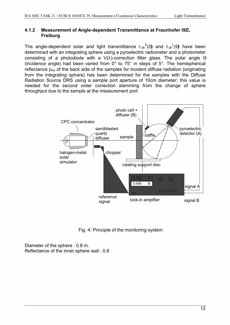
4.1.2 Measurement of Angle-dependent Transmittance at Fraunhofer ISE,Freiburg
The angle-dependent solar and light transmittance τ dhS(Θ) and τ dh
L(Θ) have beendetermined with an integrating sphere using a pyroelectric radiometer and a photometerconsisting of a photodiode with a V(λ)-correction filter glass. The polar angle Θ(incidence angle) had been varied from 0° to 75° in steps of 5°. The hemisphericalreflectance ρhh of the back side of the samples for incident diffuse radiation (originatingfrom the integrating sphere) has been determined for the samples with the DiffuseRadiation Source DRS using a sample port aperture of 10cm diameter; this value isneeded for the second order correction stemming from the change of spherethroughput due to the sample at the measurement port.
halogen-metal solar simulator
photo cell + diffuser (B)
0.123 A 0.456 B
CPC concentratorsandblasted quartz diffuser
chopper
sample baffle
reference signal signal B
signal A
lock-in amplifier
rotating support disc
pyroelectric detector (A)
Fig. 4: Principle of the monitoring system
Diameter of the sphere : 0.8 m.Reflectance of the inner sphere wall : 0.8
IEA SHC TASK 21 / ECBCS ANNEX 29, Measurement of Luminous Characteristics Light Transmittance
13
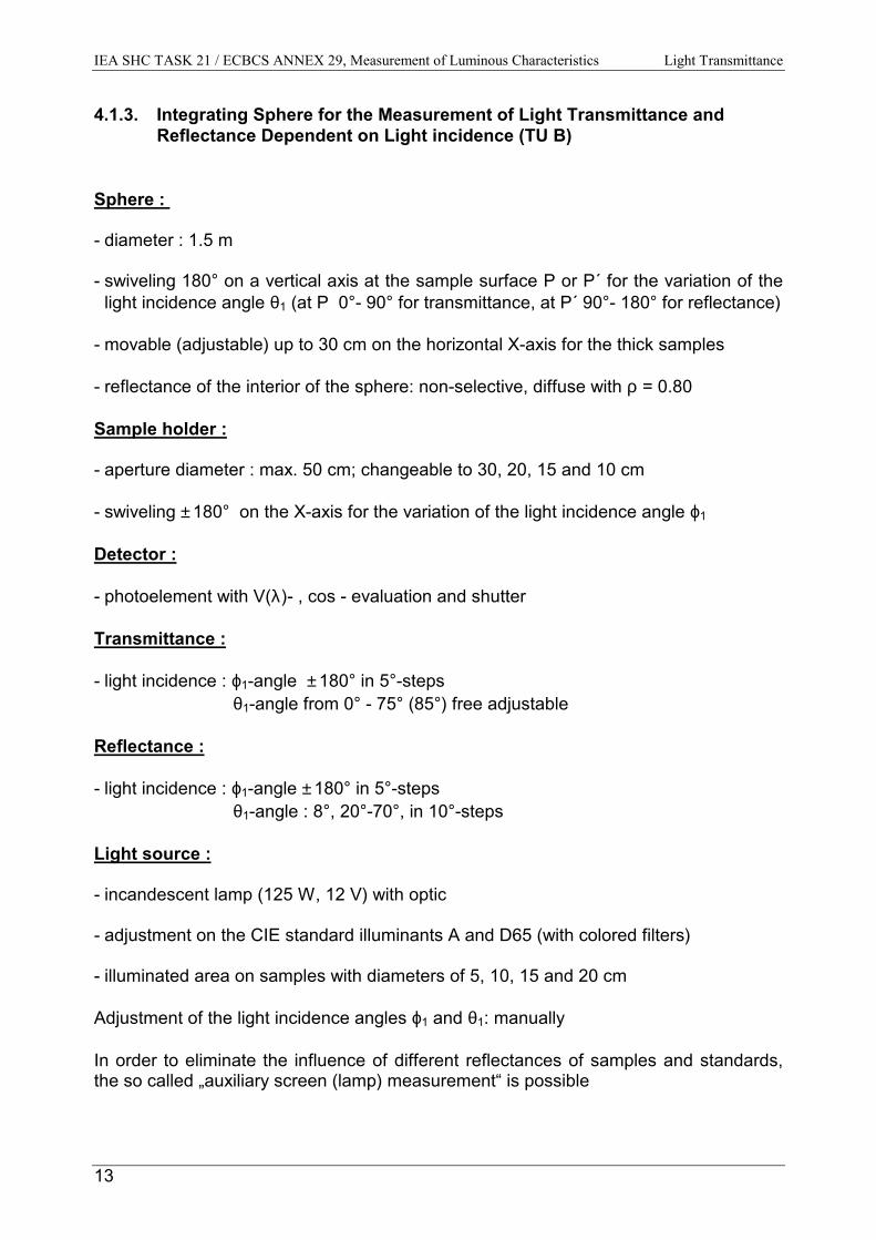
4.1.3. Integrating Sphere for the Measurement of Light Transmittance andReflectance Dependent on Light incidence (TU B)
Sphere :
- diameter : 1.5 m
- swiveling 180° on a vertical axis at the sample surface P or P´ for the variation of thelight incidence angle θ1 (at P 0°- 90° for transmittance, at P´ 90°- 180° for reflectance)
- movable (adjustable) up to 30 cm on the horizontal X-axis for the thick samples
- reflectance of the interior of the sphere: non-selective, diffuse with ρ = 0.80
Sample holder :
- aperture diameter : max. 50 cm; changeable to 30, 20, 15 and 10 cm
- swiveling ± 180° on the X-axis for the variation of the light incidence angle ϕ1
Detector :
- photoelement with V(λ)- , cos - evaluation and shutter
Transmittance :
- light incidence : ϕ1-angle ± 180° in 5°-steps θ1-angle from 0° - 75° (85°) free adjustable
Reflectance :
- light incidence : ϕ1-angle ± 180° in 5°-steps θ1-angle : 8°, 20°-70°, in 10°-steps
Light source :
- incandescent lamp (125 W, 12 V) with optic
- adjustment on the CIE standard illuminants A and D65 (with colored filters)
- illuminated area on samples with diameters of 5, 10, 15 and 20 cm
Adjustment of the light incidence angles ϕ1 and θ1: manually
In order to eliminate the influence of different reflectances of samples and standards,the so called „auxiliary screen (lamp) measurement“ is possible
IEA SHC TASK 21 / ECBCS ANNEX 29, Measurement of Luminous Characteristics Light Transmittance
14
Fig. 5: Top view of the integrating sphere
Vertical axis of swivelingat pointsP for transmittance 0° - 90°P´ for reflectance 90° - 180°
Light incidence
Sample holder
ϕ1-angleLightsource
X
Sample
Baffle
Detector
P
Swiveling of thesphere for ε1 angle0° -180°
∅ 500
30 cm
750
P´
Slots for light incidence of reflectance8°, 20° - 70°, step 10°
Aperture
IEA SHC TASK 21 / ECBCS ANNEX 29, Measurement of Luminous Characteristics Light Transmittance
15
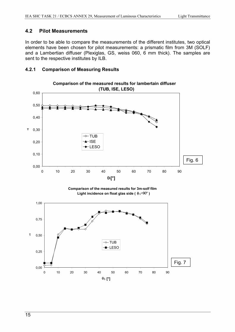
4.2 Pilot Measurements
In order to be able to compare the measurements of the different institutes, two opticalelements have been chosen for pilot measurements: a prismatic film from 3M (SOLF)and a Lambertian diffuser (Plexiglas, GS, weiss 060, 6 mm thick). The samples aresent to the respective institutes by ILB.
4.2.1 Comparison of Measuring Results
Comparison of the measured results for lambertain diffuser(TUB, ISE, LESO)
0,00
0,10
0,20
0,30
0,40
0,50
0,60
0 10 20 30 40 50 60 70 80 90
θ1[°]
τTUBISELESO
Comparison of the measured results for 3m-solf filmLight incidence on float glas side ( ϕ1=90° )
0,00
0,25
0,50
0,75
1,00
0 10 20 30 40 50 60 70 80 90
θ1 [°]
τ
TUBLESO
7
Fig. 6
Fig.

IEA SHC TASK 21 / ECBCS ANNEX 29, Measurement of Luminous Characteristics Light Transmittance
Transmittance of laser cut panel(TUB, LESO)
0,00
0,25
0,50
0,75
1,00
0 15 30 45 60 75 90
θ1 [°]
τ
C0 LESO/ Phi_1=90°LESO / Phi_1=270°TUB / Phi_1=270°TUB /Phi_1=90°
Light Transmittance of prismatic SOLF Film Light incidence on prismatic side (TUB, LESO)
0,00
0,25
0,50
0,75
1,00
0 15 30 45 60 75 90
θ1 [°]
τ
LESO / Phi_1=90°LESO / Phi_1=270°TUB / Phi_1=90°
Considering different parameters affecting the characteristics (see Csources (see Ch. 4.2.2), the achieved results show a relatively good particular values of the light transmittance depending on the light inci5%).
Fig. 8
d
Fig. 9
16
h. 2.2) and erroragreement of theence (generally ≤
IEA SHC TASK 21 / ECBCS ANNEX 29, Measurement of Luminous Characteristics Light Transmittance
17
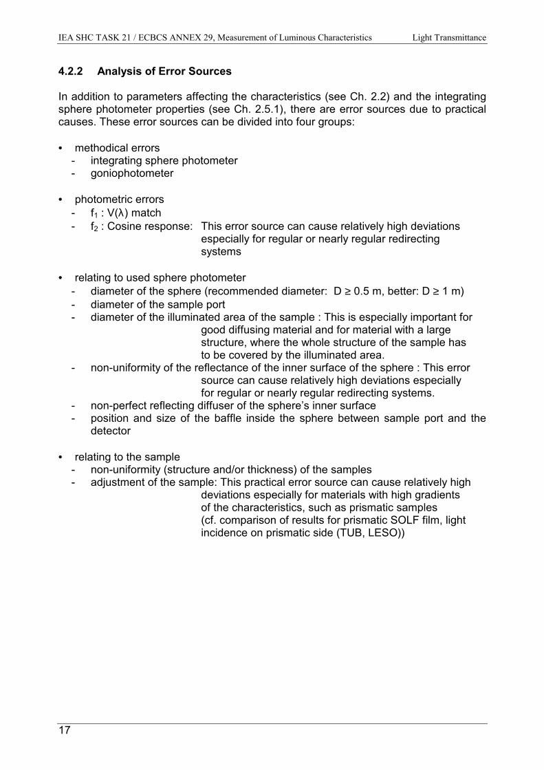
4.2.2 Analysis of Error Sources
In addition to parameters affecting the characteristics (see Ch. 2.2) and the integratingsphere photometer properties (see Ch. 2.5.1), there are error sources due to practicalcauses. These error sources can be divided into four groups:
• methodical errors- integrating sphere photometer- goniophotometer
• photometric errors- f1 : V(λ) match - f2 : Cosine response: This error source can cause relatively high deviations
especially for regular or nearly regular redirectingsystems
• relating to used sphere photometer- diameter of the sphere (recommended diameter: D ≥ 0.5 m, better: D ≥ 1 m)- diameter of the sample port- diameter of the illuminated area of the sample : This is especially important for
good diffusing material and for material with a large structure, where the whole structure of the sample has
to be covered by the illuminated area.- non-uniformity of the reflectance of the inner surface of the sphere : This error
source can cause relatively high deviations especiallyfor regular or nearly regular redirecting systems.
- non-perfect reflecting diffuser of the sphere’s inner surface- position and size of the baffle inside the sphere between sample port and the
detector
• relating to the sample- non-uniformity (structure and/or thickness) of the samples- adjustment of the sample: This practical error source can cause relatively high
deviations especially for materials with high gradients of the characteristics, such as prismatic samples (cf. comparison of results for prismatic SOLF film, light incidence on prismatic side (TUB, LESO))
IEA SHC TASK 21 / ECBCS ANNEX 29, Measurement of Luminous Characteristics Light Transmittance
18
4.3 Light Transmittance Measurement of Daylighting Systems
Light transmittance measurements as a function of light incidence describe the ratio oftransmitted luminous flux to the incident luminous flux. Since the two angles ϕ1 and θ1change over a wide range, a lot of data has to be stored and, in subsequent steps,presented. A detailed description of the data format and the presentation of the resultsis given in the following sections.
4.3.1 Data Format
One of the most important aspects in storing any kind of data that should be accessedby many users is to have a device independent format. Therefore, an ASCII file issuggested for the measurement results of light transmittance measurements. Such filescan easily be read on nearly any operating system.Since the results of the measurements sometimes show very high gradients, it is oftennot sufficient to store the data in a uniform incident angle grid. It makes a lot moresense to scan areas of interest with a smaller grid. To keep the files size quite small,such a grid does not necessarily need to be used for regions where the results do notchange a lot. A uniform grid therefore allows both, a good description of the daylightelement and no waste of disk space.
Note: A uniform grid is just a special case of a non-uniform grid. It is not forbidden to save the data in auniform grid. In some cases (diffuse transmitting elements) it is recommended to have a uniformgrid.
The data format for light transmittance measurements can be divided into two parts:header section and data section. The header contains basic information about theelement and its symmetry (see example for details). Within the data section the rangeof the incident angles are given. After that each line of the file contains three valuesseparated by the so-called tab-character (ASCII code 9). The first two valuescorrespond to the incident angles ϕ1 and θ1. The third value is the light transmittance.
In the following lines the beginning of a typical light transmittance measurement file witha non-uniform grid is given:
Note: The lines in square brackets do not belong to the data file.
[HEADER SECTION]#material: prismatic film#manufacturer: 3M#Isym=4 ! symmetry indicator: 0 no symmetry (phi_1 = 0°...360°)# 1 rotary symmetry (only for one phi_1)# 2 symmetry to phi=0° and phi=180° (phi_1 = 0°...180°)# 3 symmetry to phi=90° and phi=270° (phi_1 = -90°...90°)# 4 symmetry to phi=0° & phi=180° and to phi=90° & phi=270°(phi_1=0°...90°)#measurements done at TU-Berlin Institute of Electronics and LightingTechnology#measurements by Ali Sit, Berit Herrmann and Sirri Aydinli #date of measurements: 3. March 1998#contact [email protected]#light incidence:#phi_1-range: 0°...90° (azimuth)#theta_1-range: 0°...70° (altitude)#light transmittance for hemispherical light incidence : 0.49
IEA SHC TASK 21 / ECBCS ANNEX 29, Measurement of Luminous Characteristics Light Transmittance
19
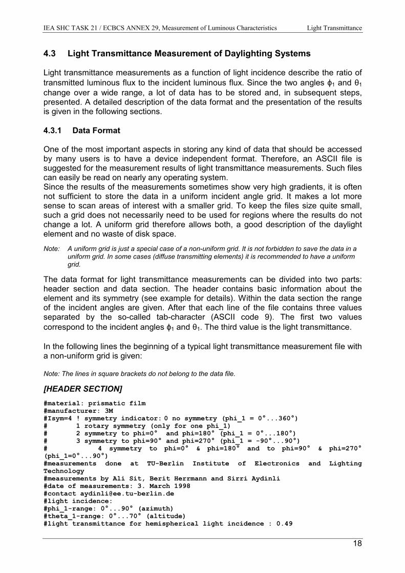
[DATA SECTION]
#data#phi_1 theta_1 tau0.000000e+000 0.000000e+000 2.503987e-0020.000000e+000 2.500000e+000 2.500000e-0020.000000e+000 5.000000e+000 2.500000e-0020.000000e+000 7.500000e+000 2.424242e-0020.000000e+000 1.000000e+001 2.424242e-0020.000000e+000 1.250000e+001 2.272727e-0020.000000e+000 1.500000e+001 2.272727e-0020.000000e+000 2.000000e+001 2.121212e-0020.000000e+000 2.500000e+001 2.045455e-0020.000000e+000 3.000000e+001 1.893939e-0020.000000e+000 3.500000e+001 1.818182e-002[a.s.o.]END
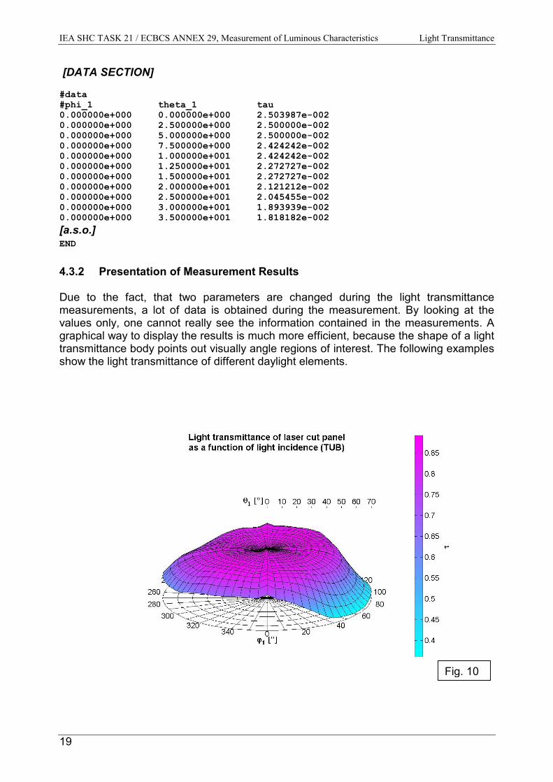
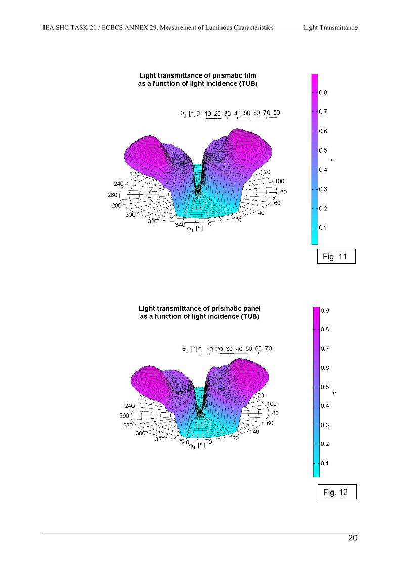
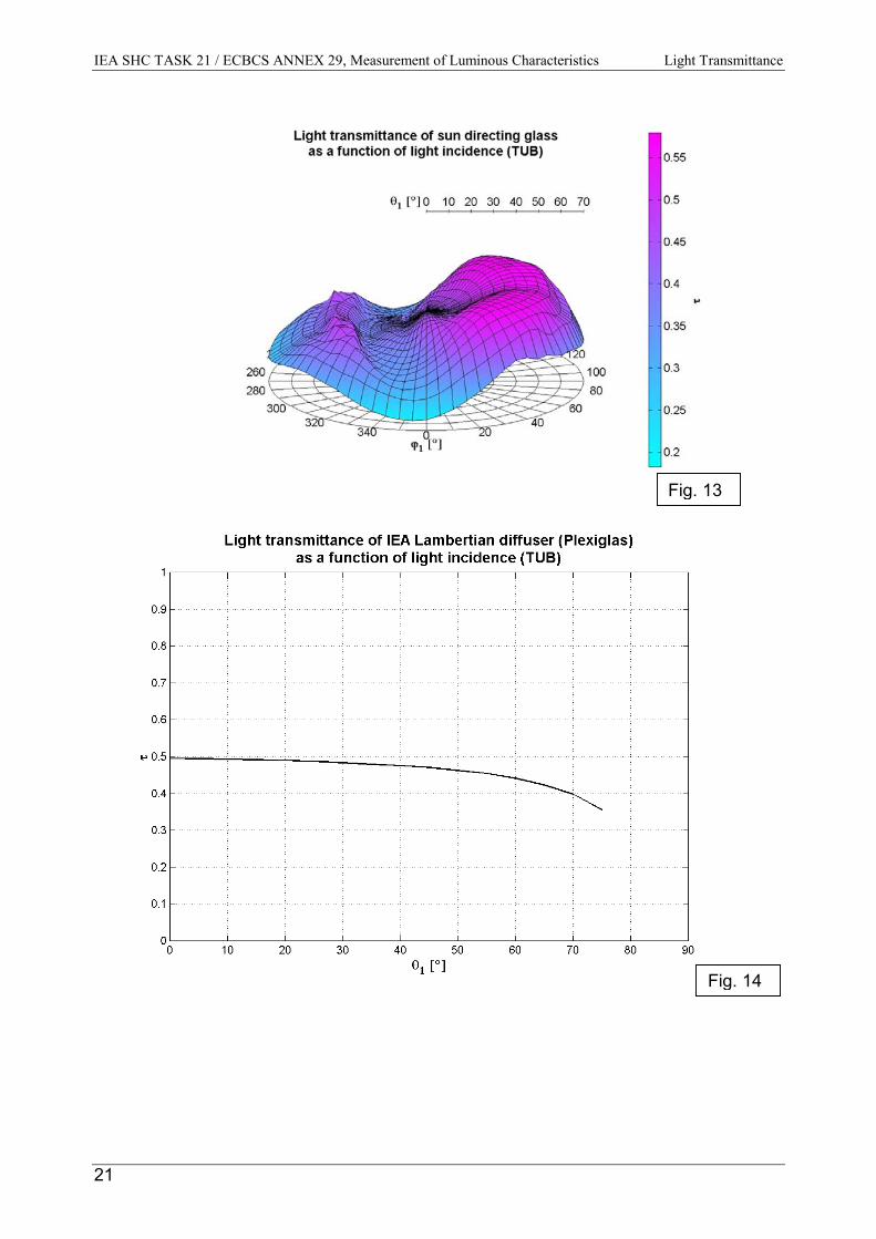
4.3.2 Presentation of Measurement Results
Due to the fact, that two parameters are changed during the light transmittancemeasurements, a lot of data is obtained during the measurement. By looking at thevalues only, one cannot really see the information contained in the measurements. Agraphical way to display the results is much more efficient, because the shape of a lighttransmittance body points out visually angle regions of interest. The following examplesshow the light transmittance of different daylight elements.
Fig. 10
IEA SHC TASK 21 / ECBCS ANNEX 29, Measurement of Luminous Characteristics Light Transmittance
Fig. 11
Fig. 12
20
IEA SHC TASK 21 / ECBCS ANNEX 29, Measurement of Luminous Characteristics Light Transmittance
21
Fig. 13
Fig. 14
IEA SHC TASK 21 / ECBCS ANNEX 29, Measurement of Luminous Characteristics Light Transmittance
22
FilenamesAll the data as well as the presentation of the sample measurements are included onthe CD-ROM to this report. All measurements are put to one compressed file("tub_tau.zip") containing the data files (text files) and one WINWORD document whichincludes the presentation of the measurement results.
4.3.3 Light Transmittance for Hemispherical Light Incidence
The light transmittance for hemispherical light incidence τ dif is defined as the lighttransmission for an illumination with nearly uniform luminance from the hemisphere.This quantity could be measured using a hemisphere (or sphere) to illuminate thesample. It can also be derived from the integration of the light transmittancemeasurements:
( ) ( )∫ ∫π
=ϕ
π
=θ
ϕ⋅θ⋅θ⋅θϕτπ
=τ2
0
2
011111dif
1 1
dd2sin,21 (9)
For a rotation symmetrical light transmittance:
( ) ( )∫=
⋅⋅=2
0111
1
2sin
π
θ
θθθττ ddif (10)
Comparison of values τ dif for hemispherical light incidence
To check the calculated and measured values of light transmittance for hemisphericallight incidence, an example is given for plexiglas:
TUB: calculated value acc. to formula (10) 0.45ISE: measured 0.44
IEA SHC TASK 21 / ECBCS ANNEX 29, Measurement of Luminous Characteristics Bi-directional Measurements
23
5 BI-DIRECTIONAL MEASUREMENTS For the bi-directional measurements of selected daylighting systems dependent on lightincidence, the following measuring facilities of different institutes are available.
5.1 Description of the Measuring Facilities
5.1.1 Bi-directional Goniophotometer for advanced glazing materials based ondigital imaging techniques (EPFL)
Solar Energy and Building Physics Laboratory (LESO-PB)Swiss Federal Institute of Technology (EPFL)
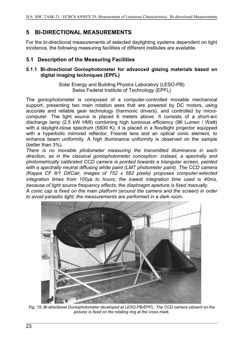
The goniophotometer is composed of a computer-controlled movable mechanicalsupport, presenting two main rotation axes that are powered by DC motors, usingaccurate and reliable gear technology (harmonic drivers), and controlled by micro-computer. The light source is placed 6 meters above. It consists of a short-arcdischarge lamp (2.5 kW HMI) combining high luminous efficiency (96 Lumen / Watt)with a daylight-close spectrum (5600 K); it is placed in a floodlight projector equippedwith a hyperbolic mirrored reflector, Fresnel lens and an optical conic element, toenhance beam uniformity. A high illuminance uniformity is observed on the sample(better than 3%). There is no movable photometer measuring the transmitted illuminance in eachdirection, as in the classical goniophotometer conception: instead, a spectrally andphotometrically calibrated CCD camera is pointed towards a triangular screen, paintedwith a spectrally neutral diffusing white paint (LMT photometer paint). The CCD camera(Kappa CF 8/1 DXCair, images of 752 x 582 pixels) proposes computer-selectedintegration times from 100µs to hours; the lowest integration time used is 40ms,because of light source frequency effects; the diaphragm aperture is fixed manually. A conic cap is fixed on the main platform (around the camera and the screen) in orderto avoid parasitic light; the measurements are performed in a dark room.
Fig. 15: Bi-directional Goniophotometer developed at LESO-PB/EPFL. The CCD camera (absent on thepicture) is fixed on the rotating ring at the cross mark.
IEA SHC TASK 21 / ECBCS ANNEX 29, Measurement of Luminous Characteristics Bi-directional Measurements
24
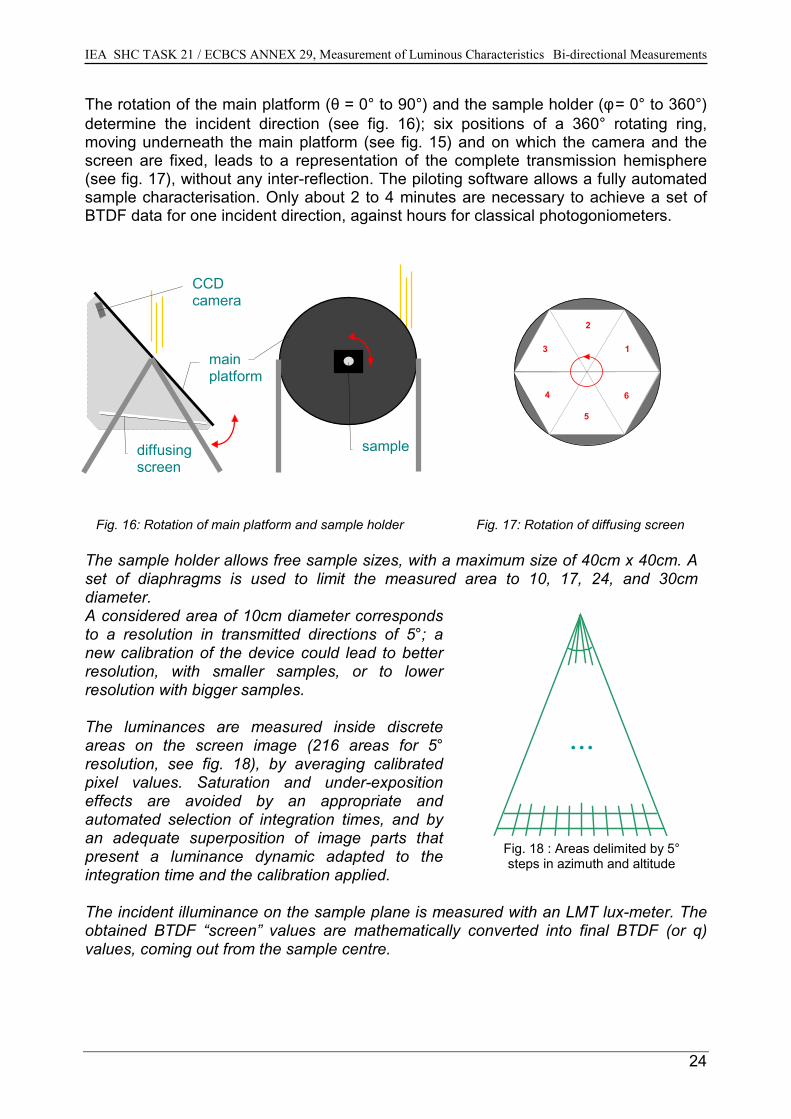
The rotation of the main platform (θ = 0° to 90°) and the sample holder (φ = 0° to 360°)determine the incident direction (see fig. 16); six positions of a 360° rotating ring,moving underneath the main platform (see fig. 15) and on which the camera and thescreen are fixed, leads to a representation of the complete transmission hemisphere(see fig. 17), without any inter-reflection. The piloting software allows a fully automatedsample characterisation. Only about 2 to 4 minutes are necessary to achieve a set ofBTDF data for one incident direction, against hours for classical photogoniometers.
Fig. 16: Rotation of main platform and sample holder Fig. 17: Rotation of diffusing screen
The sample holder allows free sample sizes, with a maximum size of 40cm x 40cm. Aset of diaphragms is used to limit the measured area to 10, 17, 24, and 30cmdiameter. A considered area of 10cm diameter correspondsto a resolution in transmitted directions of 5°; anew calibration of the device could lead to betterresolution, with smaller samples, or to lowerresolution with bigger samples.
The luminances are measured inside discreteareas on the screen image (216 areas for 5°resolution, see fig. 18), by averaging calibratedpixel values. Saturation and under-expositioneffects are avoided by an appropriate andautomated selection of integration times, and byan adequate superposition of image parts thatpresent a luminance dynamic adapted to theintegration time and the calibration applied.
The incident illuminance on the sample plane is measured with an LMT lux-meter. Theobtained BTDF “screen” values are mathematically converted into final BTDF (or q)values, coming out from the sample centre.
CCDcamera
diffusingscreen
mainplatform
sample
1
2
3
4
5
6
...
Fig. 18 : Areas delimited by 5°steps in azimuth and altitude
IEA SHC TASK 21 / ECBCS ANNEX 29, Measurement of Luminous Characteristics Bi-directional Measurements
25
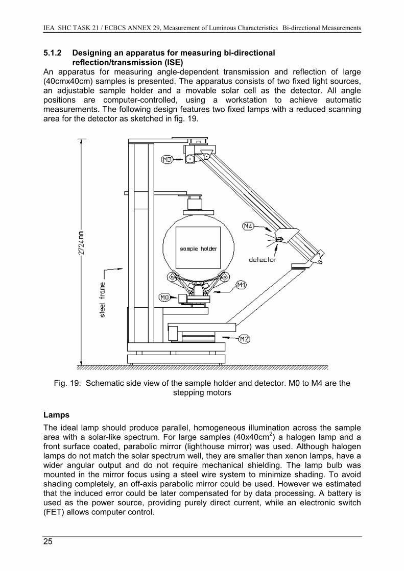
5.1.2 Designing an apparatus for measuring bi-directionalreflection/transmission (ISE)
An apparatus for measuring angle-dependent transmission and reflection of large(40cmx40cm) samples is presented. The apparatus consists of two fixed light sources,an adjustable sample holder and a movable solar cell as the detector. All anglepositions are computer-controlled, using a workstation to achieve automaticmeasurements. The following design features two fixed lamps with a reduced scanningarea for the detector as sketched in fig. 19.
Fig. 19: Schematic side view of the sample holder and detector. M0 to M4 are thestepping motors
LampsThe ideal lamp should produce parallel, homogeneous illumination across the samplearea with a solar-like spectrum. For large samples (40x40cm2) a halogen lamp and afront surface coated, parabolic mirror (lighthouse mirror) was used. Although halogenlamps do not match the solar spectrum well, they are smaller than xenon lamps, have awider angular output and do not require mechanical shielding. The lamp bulb wasmounted in the mirror focus using a steel wire system to minimize shading. To avoidshading completely, an off-axis parabolic mirror could be used. However we estimatedthat the induced error could be later compensated for by data processing. A battery isused as the power source, providing purely direct current, while an electronic switch(FET) allows computer control.
IEA SHC TASK 21 / ECBCS ANNEX 29, Measurement of Luminous Characteristics Bi-directional Measurements
26
For transmission measurements on small samples (4x4cm2) a 1kW Xe-lamp producesan 18mm diameter beam, using a 0.8mm pinhole and a photographic lens (f=125mm)to provide a parallel beam with a Gaussian cross-section. The light intensity is stabilizedby a photodetector and feedback circuits to the power source. A mechanical shutterallows control by the host computer.Sample holderThe sample has to be turned around two orthogonal axes, one perpendicular to theincident beam. In this set-up the first axis is mounted vertically for mechanical reasons.The second axis could either be parallel to the sample surface or perpendicular to it: thelatter avoids shadows cast by the mechanical hinge on the sample. The sample holderconsists of an 800mm diameter aluminium disc, 5mm thick, with a 500x500mm2 hole atthe center. T-shape aluminium mouldings are mounted around the square hole, givingmechanical stiffness and a mounting frame for the inner sample holders. Varioussample sizes and shapes have their own “inner” custom mounting.DetectorThe apparatus uses a 2x2cm2 solar cell as a detector; its short-circuit current ismeasured with a Keithley 485 Picoammeter. Since most measured results are used fordaylighting and photometric simulations, a green V(l) filter adapts the spectral sensitivityto the photopic response. The acceptance angle of the detector is designed for full viewof a 40x40cm2 sample (maximum 39°).
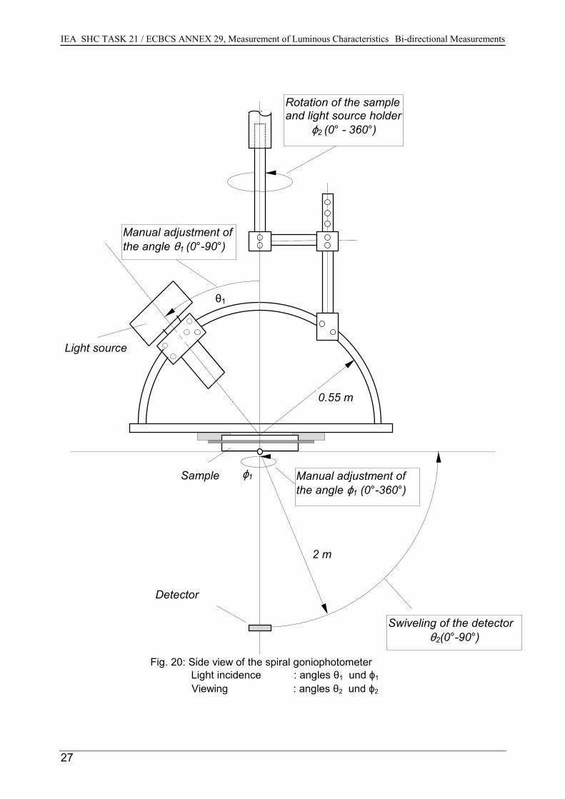
5.1.3 Short Description of the Spiral Goniophotometer for Bi-directional Measurements (TUB)
Principle : An hemispherical surface with a radius of 2 m is scanned in a spiral form by rotating thesample and the light source holder around a vertical axis and simultaneously swivelingthe detector on a horizontal axis (viewing angles ϕ2 and θ2).
Detector :- photoelement with V(λ)- and cos – evaluation
Light source :- incandescent lamp (100 W, 12 V) with optic - illuminated area on samples with a diameter of 7 cmAdjustment of the light incidence angles ϕ1 and θ1 : manually
IEA SHC TASK 21 / ECBCS ANNEX 29, Measurement of Luminous Characteristics Bi-directional Measurements
27
ϕ1
Detector
ε1
Light source
Manual adjustment ofthe angle ϕ1 (0°-360°)
Rotation of the sampleand light source holder
ϕ2 (0° - 360°)
Sample
2 m
Swiveling of the detectorθ2(0°-90°)
Fig. 20: Side view of the spiral goniophotometer Light incidence : angles θ1 und ϕ1
Viewing : angles θ2 und ϕ2
Manual adjustment ofthe angle θ1 (0°-90°)
0.55 m
θ1
IEA SHC TASK 21 / ECBCS ANNEX 29, Measurement of Luminous Characteristics Bi-directional Measurements
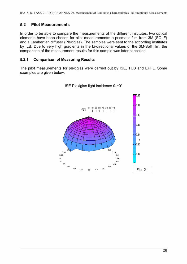
5.2 Pilot Measurements
In order to be able to compare the measurements of the different institutes, two opticalelements have been chosen for pilot measurements: a prismatic film from 3M (SOLF)and a Lambertian diffuser (Plexiglas). The samples were sent to the according institutesby ILB. Due to very high gradients in the bi-directional values of the 3M-Solf film, thecomparison of the measurement results for this sample was later cancelled.
5.2.1 Comparison of Measuring Results
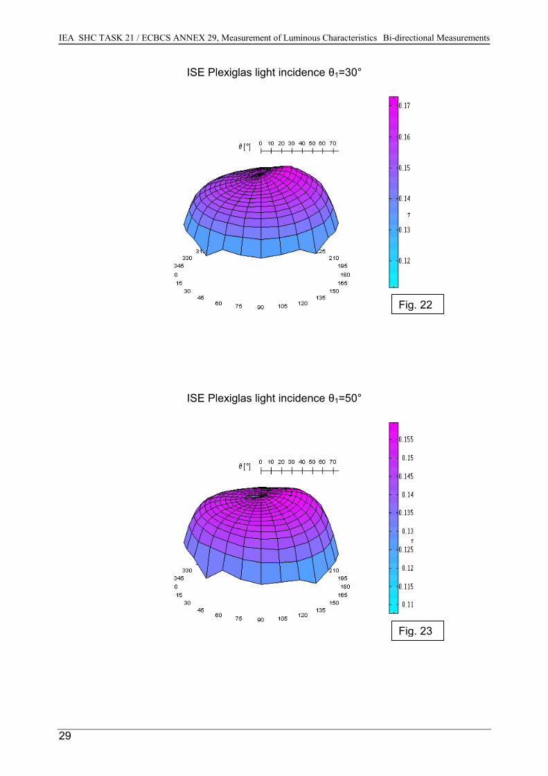
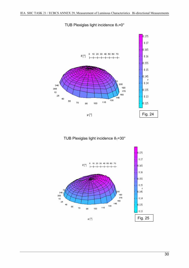
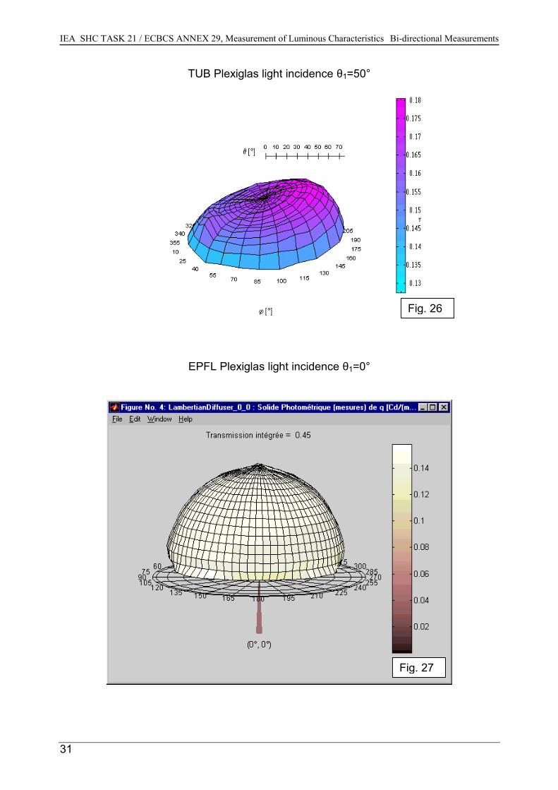
The pilot measurements for plexiglas were carried out by ISE, TUB and EPFL. Someexamples are given below:
ISE Plexiglas light incidence θ1=0°
Fig. 21
28
IEA SHC TASK 21 / ECBCS ANNEX 29, Measurement of Luminous Characteristics Bi-directional Measurements
29
ISE Plexiglas light incidence θ1=30°
ISE Plexiglas light incidence θ1=50°
Fig. 22
Fig. 23
IEA SHC TASK 21 / ECBCS ANNEX 29, Measurement of Luminous Characteristics Bi-directional Measurements
TUB Plexiglas light incidence θ1=0°
TUB Plexiglas light incidence θ1=30°
Fig. 24
Fig. 25
30
IEA SHC TASK 21 / ECBCS ANNEX 29, Measurement of Luminous Characteristics Bi-directional Measurements
31
TUB Plexiglas light incidence θ1=50°
EPFL Plexiglas light incidence θ1=0°
Fig. 26
Fig. 27
IEA SHC TASK 21 / ECBCS ANNEX 29, Measurement of Luminous Characteristics Bi-directional Measurements
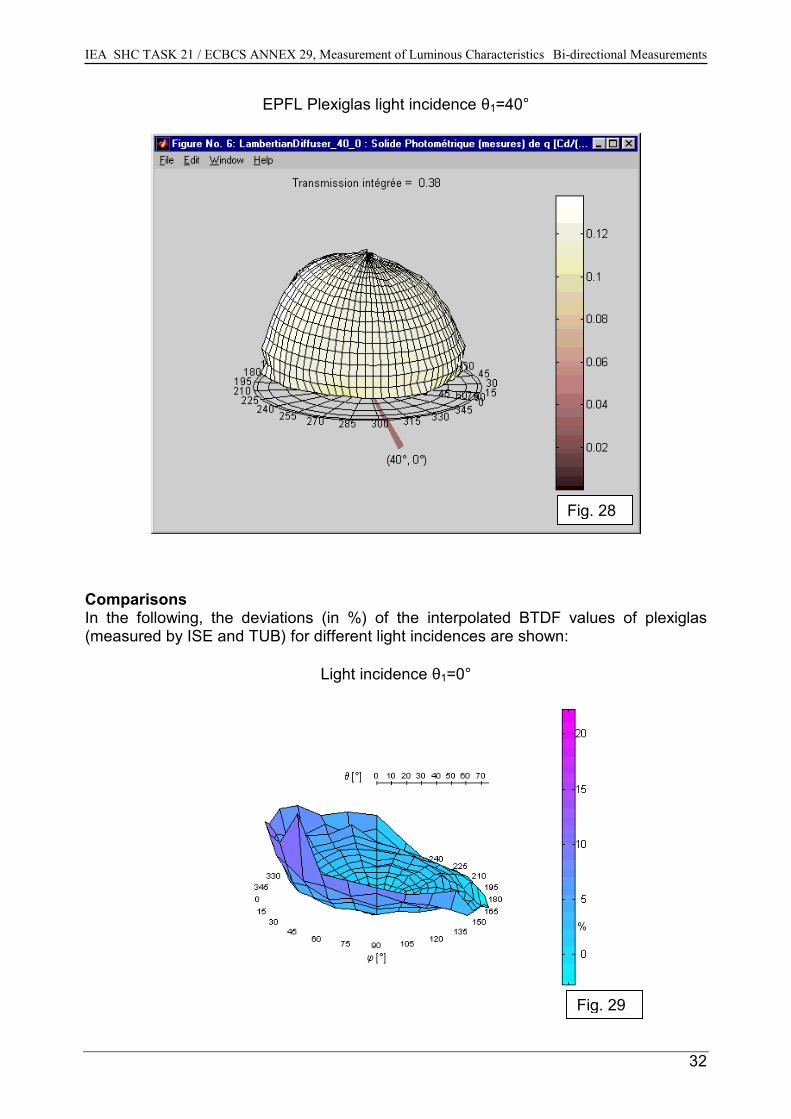
EPFL Plexiglas light incidence θ1=40°
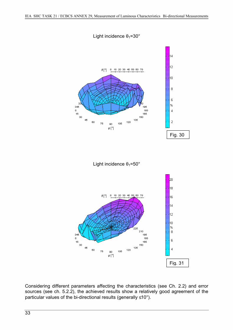
ComparisonsIn the following, the deviations (in %) of the interpolated BTDF(measured by ISE and TUB) for different light incidences are shown
Light incidence θ1=0°
Fig. 28
values of plexiglas:
Fig. 29
32
IEA SHC TASK 21 / ECBCS ANNEX 29, Measurement of Luminous Characteristics Bi-directional Measurements
33
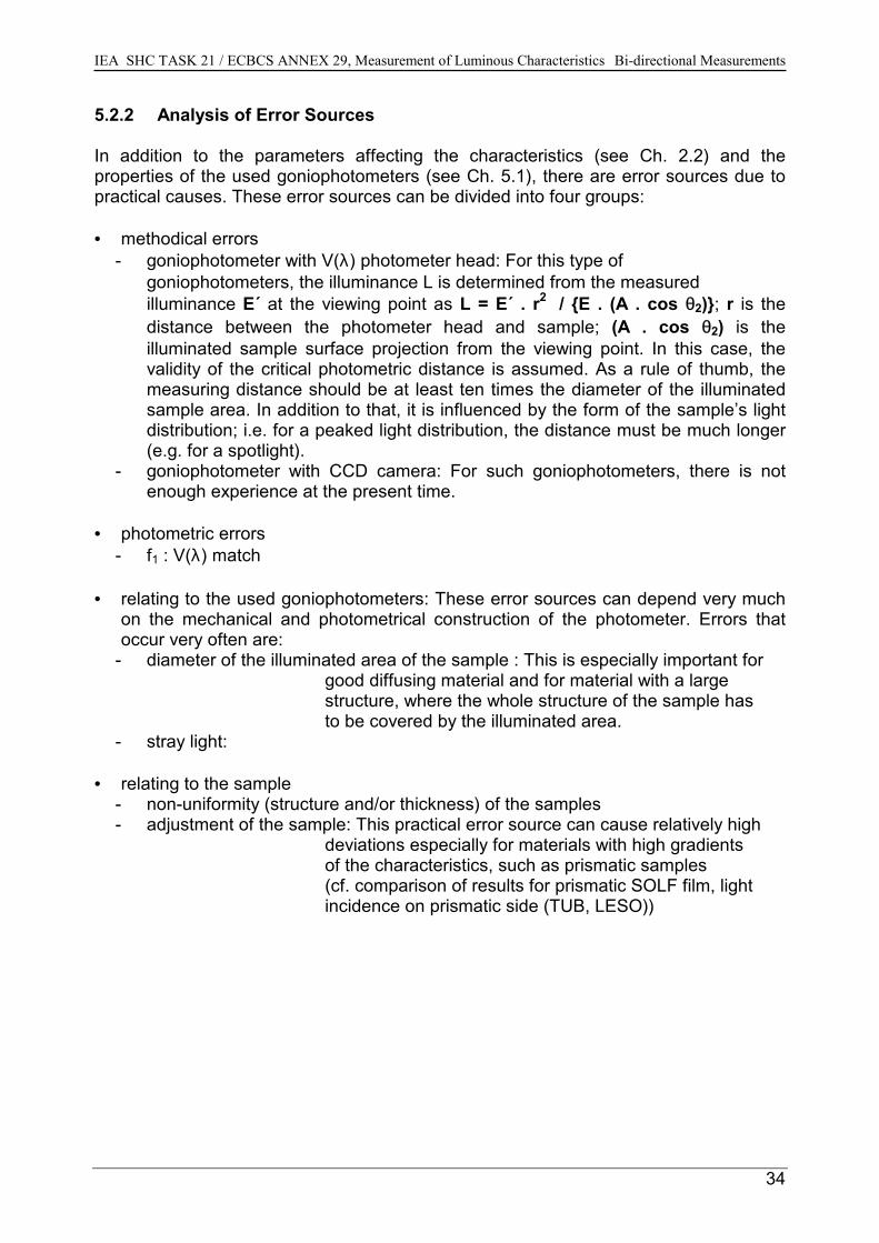
Light incidence θ1=30°
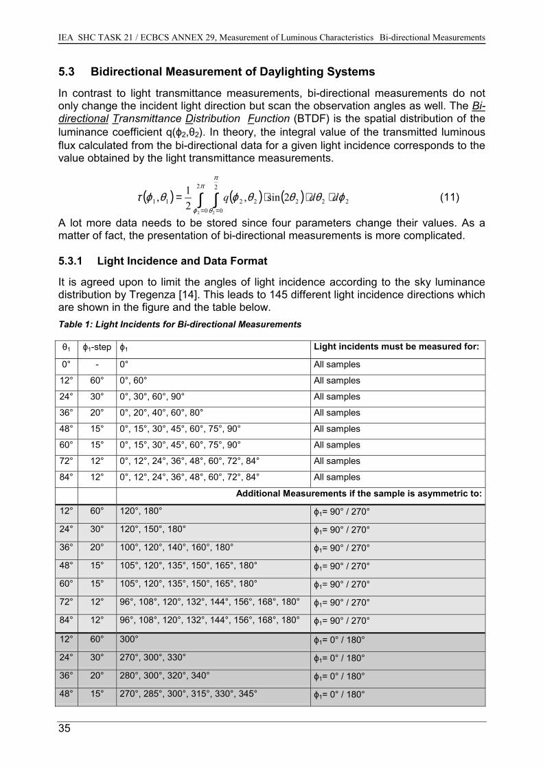
Light incidence θ1=50°
Considering different parameters affecting the characteristics (see sources (see ch. 5.2.2), the achieved results show a relatively goodparticular values of the bi-directional results (generally ≤ 10°).
Fig. 30
Fig. 31
Ch. 2.2) and error agreement of the
IEA SHC TASK 21 / ECBCS ANNEX 29, Measurement of Luminous Characteristics Bi-directional Measurements
34
5.2.2 Analysis of Error Sources
In addition to the parameters affecting the characteristics (see Ch. 2.2) and theproperties of the used goniophotometers (see Ch. 5.1), there are error sources due topractical causes. These error sources can be divided into four groups:
• methodical errors- goniophotometer with V(λ) photometer head: For this type of
goniophotometers, the illuminance L is determined from the measured illuminance E´ at the viewing point as L = E´ . r2 / {E . (A . cos θ2)}; r is thedistance between the photometer head and sample; (A . cos θ2) is theilluminated sample surface projection from the viewing point. In this case, thevalidity of the critical photometric distance is assumed. As a rule of thumb, themeasuring distance should be at least ten times the diameter of the illuminatedsample area. In addition to that, it is influenced by the form of the sample’s lightdistribution; i.e. for a peaked light distribution, the distance must be much longer(e.g. for a spotlight).
- goniophotometer with CCD camera: For such goniophotometers, there is notenough experience at the present time.
• photometric errors- f1 : V(λ) match
• relating to the used goniophotometers: These error sources can depend very muchon the mechanical and photometrical construction of the photometer. Errors thatoccur very often are:
- diameter of the illuminated area of the sample : This is especially important forgood diffusing material and for material with a large structure, where the whole structure of the sample has
to be covered by the illuminated area.- stray light:
• relating to the sample- non-uniformity (structure and/or thickness) of the samples- adjustment of the sample: This practical error source can cause relatively high
deviations especially for materials with high gradients of the characteristics, such as prismatic samples (cf. comparison of results for prismatic SOLF film, light incidence on prismatic side (TUB, LESO))
IEA SHC TASK 21 / ECBCS ANNEX 29, Measurement of Luminous Characteristics Bi-directional Measurements
35
5.3 Bidirectional Measurement of Daylighting Systems
In contrast to light transmittance measurements, bi-directional measurements do notonly change the incident light direction but scan the observation angles as well. The Bi-directional Transmittance Distribution Function (BTDF) is the spatial distribution of theluminance coefficient q(ϕ2,θ2). In theory, the integral value of the transmitted luminousflux calculated from the bi-directional data for a given light incidence corresponds to thevalue obtained by the light transmittance measurements.
( ) ( ) ( )∫ ∫= =
⋅⋅⋅=π
ϕ
π
θ
ϕθθθϕθϕτ2
0
2
02222211
2 2
2sin,21, ddq (11)
A lot more data needs to be stored since four parameters change their values. As amatter of fact, the presentation of bi-directional measurements is more complicated.
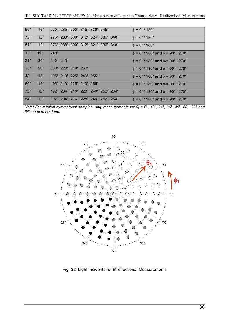
5.3.1 Light Incidence and Data Format
It is agreed upon to limit the angles of light incidence according to the sky luminancedistribution by Tregenza [14]. This leads to 145 different light incidence directions whichare shown in the figure and the table below.Table 1: Light Incidents for Bi-directional Measurements
θ1 ϕ1-step ϕ1 Light incidents must be measured for:
0° - 0° All samples
12° 60° 0°, 60° All samples
24° 30° 0°, 30°, 60°, 90° All samples
36° 20° 0°, 20°, 40°, 60°, 80° All samples
48° 15° 0°, 15°, 30°, 45°, 60°, 75°, 90° All samples
60° 15° 0°, 15°, 30°, 45°, 60°, 75°, 90° All samples
72° 12° 0°, 12°, 24°, 36°, 48°, 60°, 72°, 84° All samples
84° 12° 0°, 12°, 24°, 36°, 48°, 60°, 72°, 84° All samples
Additional Measurements if the sample is asymmetric to:
12° 60° 120°, 180° ϕ1= 90° / 270°
24° 30° 120°, 150°, 180° ϕ1= 90° / 270°
36° 20° 100°, 120°, 140°, 160°, 180° ϕ1= 90° / 270°
48° 15° 105°, 120°, 135°, 150°, 165°, 180° ϕ1= 90° / 270°
60° 15° 105°, 120°, 135°, 150°, 165°, 180° ϕ1= 90° / 270°
72° 12° 96°, 108°, 120°, 132°, 144°, 156°, 168°, 180° ϕ1= 90° / 270°
84° 12° 96°, 108°, 120°, 132°, 144°, 156°, 168°, 180° ϕ1= 90° / 270°
12° 60° 300° ϕ1= 0° / 180°
24° 30° 270°, 300°, 330° ϕ1= 0° / 180°
36° 20° 280°, 300°, 320°, 340° ϕ1= 0° / 180°
48° 15° 270°, 285°, 300°, 315°, 330°, 345° ϕ1= 0° / 180°
IEA SHC TASK 21 / ECBCS ANNEX 29, Measurement of Luminous Characteristics Bi-directional Measurements
36
60° 15° 270°, 285°, 300°, 315°, 330°, 345° ϕ1= 0° / 180°
72° 12° 276°, 288°, 300°, 312°, 324°, 336°, 348° ϕ1= 0° / 180°
84° 12° 276°, 288°, 300°, 312°, 324°, 336°, 348° ϕ1= 0° / 180°
12° 60° 240° ϕ1= 0° / 180° and ϕ1= 90° / 270°
24° 30° 210°, 240° ϕ1= 0° / 180° and ϕ1= 90° / 270°
36° 20° 200°, 220°, 240°, 260°, ϕ1= 0° / 180° and ϕ1= 90° / 270°
48° 15° 195°, 210°, 225°, 240°, 255° ϕ1= 0° / 180° and ϕ1= 90° / 270°
60° 15° 195°, 210°, 225°, 240°, 255° ϕ1= 0° / 180° and ϕ1= 90° / 270°
72° 12° 192°, 204°, 216°, 228°, 240°, 252°, 264° ϕ1= 0° / 180° and ϕ1= 90° / 270°
84° 12° 192°, 204°, 216°, 228°, 240°, 252°, 264° ϕ1= 0° / 180° and ϕ1= 90° / 270°
Note: For rotation symmetrical samples, only measurements for θ1 = 0°, 12°, 24°, 36°, 48°, 60°, 72° and84° need to be done.
Fig. 32: Light Incidents for Bi-directional Measurements
θ1
ϕ1
IEA SHC TASK 21 / ECBCS ANNEX 29, Measurement of Luminous Characteristics Bi-directional Measurements
37
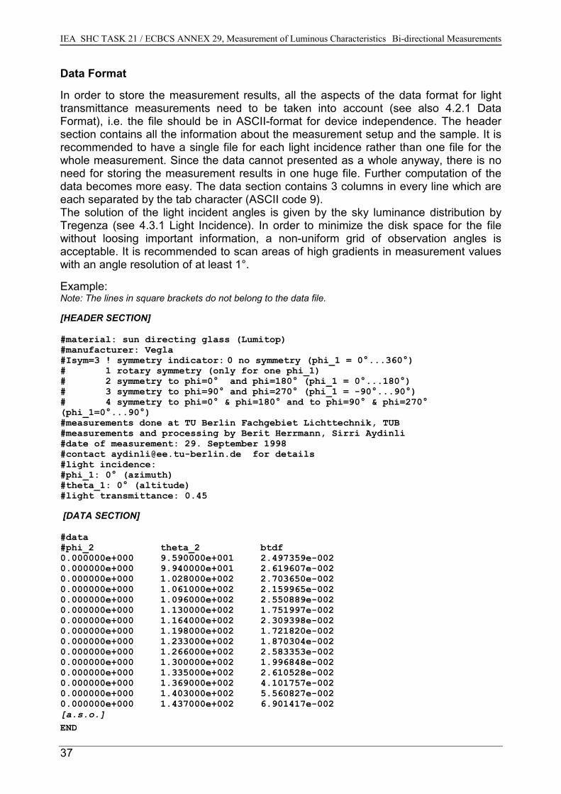
Data Format
In order to store the measurement results, all the aspects of the data format for lighttransmittance measurements need to be taken into account (see also 4.2.1 DataFormat), i.e. the file should be in ASCII-format for device independence. The headersection contains all the information about the measurement setup and the sample. It isrecommended to have a single file for each light incidence rather than one file for thewhole measurement. Since the data cannot presented as a whole anyway, there is noneed for storing the measurement results in one huge file. Further computation of thedata becomes more easy. The data section contains 3 columns in every line which areeach separated by the tab character (ASCII code 9). The solution of the light incident angles is given by the sky luminance distribution byTregenza (see 4.3.1 Light Incidence). In order to minimize the disk space for the filewithout loosing important information, a non-uniform grid of observation angles isacceptable. It is recommended to scan areas of high gradients in measurement valueswith an angle resolution of at least 1°.
Example:Note: The lines in square brackets do not belong to the data file.
[HEADER SECTION]
#material: sun directing glass (Lumitop)#manufacturer: Vegla#Isym=3 ! symmetry indicator: 0 no symmetry (phi_1 = 0°...360°)# 1 rotary symmetry (only for one phi_1)# 2 symmetry to phi=0° and phi=180° (phi_1 = 0°...180°)# 3 symmetry to phi=90° and phi=270° (phi_1 = -90°...90°)# 4 symmetry to phi=0° & phi=180° and to phi=90° & phi=270°(phi_1=0°...90°)#measurements done at TU Berlin Fachgebiet Lichttechnik, TUB#measurements and processing by Berit Herrmann, Sirri Aydinli#date of measurement: 29. September 1998#contact [email protected] for details#light incidence:#phi_1: 0° (azimuth)#theta_1: 0° (altitude)#light transmittance: 0.45
[DATA SECTION]
#data#phi_2 theta_2 btdf0.000000e+000 9.590000e+001 2.497359e-0020.000000e+000 9.940000e+001 2.619607e-0020.000000e+000 1.028000e+002 2.703650e-0020.000000e+000 1.061000e+002 2.159965e-0020.000000e+000 1.096000e+002 2.550889e-0020.000000e+000 1.130000e+002 1.751997e-0020.000000e+000 1.164000e+002 2.309398e-0020.000000e+000 1.198000e+002 1.721820e-0020.000000e+000 1.233000e+002 1.870304e-0020.000000e+000 1.266000e+002 2.583353e-0020.000000e+000 1.300000e+002 1.996848e-0020.000000e+000 1.335000e+002 2.610528e-0020.000000e+000 1.369000e+002 4.101757e-0020.000000e+000 1.403000e+002 5.560827e-0020.000000e+000 1.437000e+002 6.901417e-002[a.s.o.]END
IEA SHC TASK 21 / ECBCS ANNEX 29, Measurement of Luminous Characteristics Bi-directional Measurements
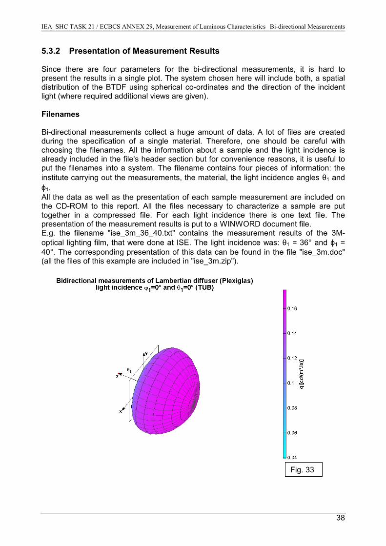
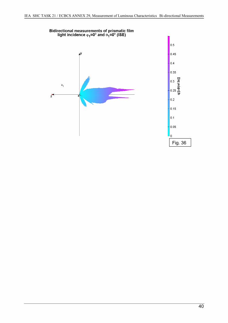
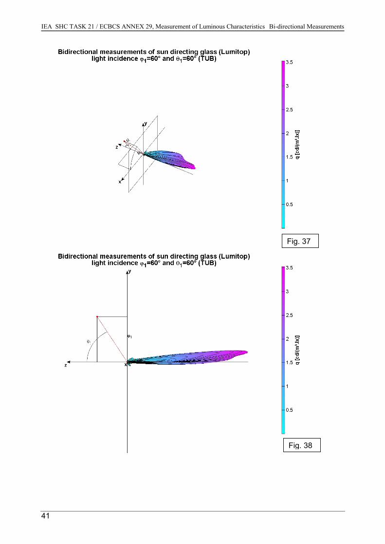
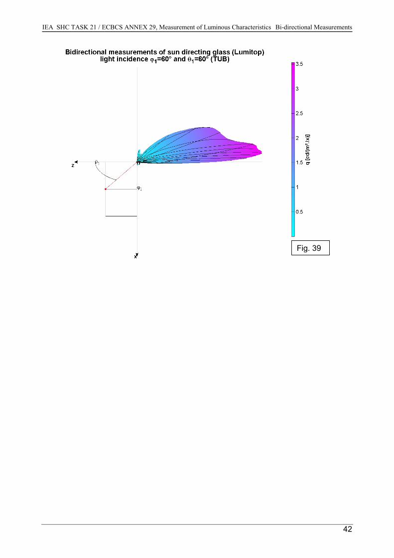
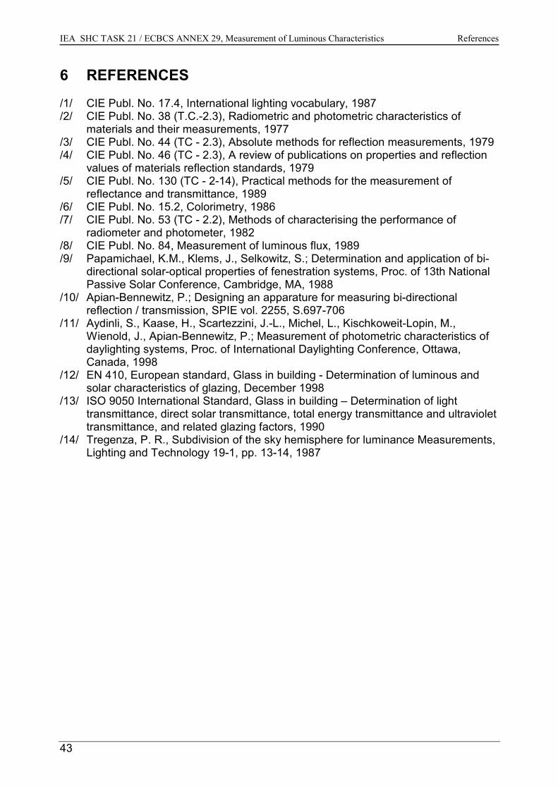
5.3.2 Presentation of Measurement Results
Since there are four parameters for the bi-directional measurements, it is hard topresent the results in a single plot. The system chosen here will include both, a spatialdistribution of the BTDF using spherical co-ordinates and the direction of the incidentlight (where required additional views are given).
Filenames
Bi-directional measurements collect a huge amount of data. A lot of files are createdduring the specification of a single material. Therefore, one should be careful withchoosing the filenames. All the information about a sample and the light incidence isalready included in the file's header section but for convenience reasons, it is useful toput the filenames into a system. The filename contains four pieces of information: theinstitute carrying out the measurements, the material, the light incidence angles θ1 andϕ1.All the data as well as the presentation of each sample measurement are included onthe CD-ROM to this report. All the files necessary to characterize a sample are puttogether in a compressed file. For each light incidence there is one text file. Thepresentation of the measurement results is put to a WINWORD document file.E.g. the filename "ise_3m_36_40.txt" contains the measurement results of the 3M-optical lighting film, that were done at ISE. The light incidence was: θ1 = 36° and ϕ1 =40°. The corresponding presentation of this data can be found in the file "ise_3m.doc"(all the files of this example are included in "ise_3m.zip").
Fig. 33
38

IEA SHC TASK 21 / ECBCS ANNEX 29, Measurement of Luminous Characteristics Bi-directional Measurements
39
Fig. 34
Fig. 35
IEA SHC TASK 21 / ECBCS ANNEX 29, Measurement of Luminous Characteristics Bi-directional Measurements
Fig. 36
40
IEA SHC TASK 21 / ECBCS ANNEX 29, Measurement of Luminous Characteristics Bi-directional Measurements
41
Fig. 37
Fig. 38
IEA SHC TASK 21 / ECBCS ANNEX 29, Measurement of Luminous Characteristics Bi-directional Measurements
Fig. 39
42
IEA SHC TASK 21 / ECBCS ANNEX 29, Measurement of Luminous Characteristics References
43
6 REFERENCES
/1/ CIE Publ. No. 17.4, International lighting vocabulary, 1987/2/ CIE Publ. No. 38 (T.C.-2.3), Radiometric and photometric characteristics of
materials and their measurements, 1977/3/ CIE Publ. No. 44 (TC - 2.3), Absolute methods for reflection measurements, 1979/4/ CIE Publ. No. 46 (TC - 2.3), A review of publications on properties and reflection
values of materials reflection standards, 1979/5/ CIE Publ. No. 130 (TC - 2-14), Practical methods for the measurement of
reflectance and transmittance, 1989/6/ CIE Publ. No. 15.2, Colorimetry, 1986/7/ CIE Publ. No. 53 (TC - 2.2), Methods of characterising the performance of
radiometer and photometer, 1982/8/ CIE Publ. No. 84, Measurement of luminous flux, 1989/9/ Papamichael, K.M., Klems, J., Selkowitz, S.; Determination and application of bi-
directional solar-optical properties of fenestration systems, Proc. of 13th NationalPassive Solar Conference, Cambridge, MA, 1988
/10/ Apian-Bennewitz, P.; Designing an apparature for measuring bi-directionalreflection / transmission, SPIE vol. 2255, S.697-706
/11/ Aydinli, S., Kaase, H., Scartezzini, J.-L., Michel, L., Kischkoweit-Lopin, M.,Wienold, J., Apian-Bennewitz, P.; Measurement of photometric characteristics ofdaylighting systems, Proc. of International Daylighting Conference, Ottawa,Canada, 1998
/12/ EN 410, European standard, Glass in building - Determination of luminous andsolar characteristics of glazing, December 1998
/13/ ISO 9050 International Standard, Glass in building – Determination of lighttransmittance, direct solar transmittance, total energy transmittance and ultraviolettransmittance, and related glazing factors, 1990
/14/ Tregenza, P. R., Subdivision of the sky hemisphere for luminance Measurements,Lighting and Technology 19-1, pp. 13-14, 1987

IEA SHC TASK 21 / ECBCS ANNEX 29, Measurement of Luminous Characteristics List of Contact Persons
44
7 LIST OF CONTACT PERSONS
Task 21 & Annex 29 Operating Agent:
Kjeld JohnsonDanish Building Research InstituteEnergy and Indoor Climate DivisionDr. Neergards Vej 15Postboks 119DK - 2970 Hørsholm, DenmarkTel: +45 45 86 55 33Tel(direkte): +45 45 76 74 33 + 387Fax: +45 45 86 75 35E-mail: [email protected]
Leader Subtask A:Nancy RuckUniversity of SydneyDept. of Architecture & Design Science79 Amaroo Drive, Smiths LakeSydney NSW 2006, AustraliaTel: +61 2 65 544073Fax: +61 2 65 544073E-mail: [email protected]
Leader Subtask B:Laurens ZonnefeldtTNO-TUECentre for Building ResearchP.O.Box 513NL - 5600 MB Eindhoven, The NetherlandsTel: +31 40 247 2814Fax: +31 40 243 8595E-mail: [email protected]
Leader Subtask C:Hans Erhorn Fraunhofer Institute for Building PhysicsNobelstraße 12D - 70569 Stuttgart, GermanyTel: +49 711 970 3380Fax: +49 711 970 3399E-mail: [email protected]
IEA SHC TASK 21 / ECBCS ANNEX 29, Measurement of Luminous Characteristics List of Contact Persons
45
Leader Subtask D:Poul Erik KristensenDanisch Technological InstituteDivision of EnergyGregersensvej, P.O. Box 141DK - 2630 Taastrup, DenmarkTel. +45 43 50 45 84Fax: +45 43 50 72 22E-mail: [email protected]
IEA SHC TASK 21 / ECBCS ANNEX 29, Measurement of Luminous Characteristics List of Contact Persons
46
Members of Subtask A:
Australia:Nancy RuckUniversity of SydneyDept. of Architecture & Design Science79 Amaroo Drive, Smiths LakeSydney NSW 2006, AustraliaTel: +61 2 65 544073Fax: +61 2 65 544073E-mail: [email protected]
Austria:Martin KlinglerIngenieurbüro Martin KlinglerKaplanstrasse 2A-6063 Rum/Innsbruck, AustriaTel: +43 512 20 6057Fax : +43 512 20 6047E-mail: [email protected]
Denmark:Kjeld JohnsonDanish Building Research InstituteEnergy and Indoor Climate DivisionDr. Neergards Vej 15Postboks 119DK - 2970 Hørsholm, DenmarkTel: +45 45 86 55 33Tel(direkte): +45 45 76 74 33 + 387Fax: +45 45 86 75 35E-mail: [email protected]
Jens ChristoffersenDanish Building Research InstituteEnergy and Indoor Climate DivisionDr. Neergards Vej 15Postboks 119DK - 2970 Hørsholm, DenmarkTel: +45 45 86 55 33Tel(direkte): +45 45 76 74 33 + 389Fax: +45 45 86 75 35E-mail: [email protected]
IEA SHC TASK 21 / ECBCS ANNEX 29, Measurement of Luminous Characteristics List of Contact Persons
47
Germany:Sirri AydinliTechnische Universität BerlinFachgebiet LichttechnikSekr.: E6Einsteinufer 19D-10587 Berlin, GermanyTel: +49 30 3142 3489Faxx. +49 30 3142 2161E-mil: [email protected]
Heinrich KaaseTechnische Universität BerlinFachgebiet LichttechnikSekr.: E6Einsteinufer 19D-10587 Berlin, GermanyTel: +49 30 3142 2401Faxx. +49 30 3142 2161E-mil: [email protected]
Roman JakobiakInst. für Bau-, Umwelt- und SolarforschungCaspar Theyss Strasse 14 aD-14193 Berlin, GermanyTel: +49 30 896 9950Fax: +49 30 891 7977E-mail: [email protected]
Jan WienoldFraunhofer Institute for Solar Energy SystemsOltmannsstrasse 5D-79100 Freiburg, GermanyTel: +49 761 4588 133Fax: +49 761 4588 132E-mail: [email protected]
Martin Kischkoweit-LopinFH KölnInstitut für Licht- und BautechnikGremberger Strasse 151 a51105 Köln, GermanyTel: +49 221 83 1096Fax: +49 221 83 5513E-mail: [email protected]
IEA SHC TASK 21 / ECBCS ANNEX 29, Measurement of Luminous Characteristics List of Contact Persons
48
Norway:Heidi ArnesenNorwegian University of Science and TechnologyFaculty of ArchitecturePlanning and Fine Arts7491 Trondheim, NorwayTel: +47 73 59 3346Fax: +47 73 59 5045E-mail: [email protected]
Oyvind AschehougNorwegian University of Science and TechnologyFaculty of ArchitecturePlanning and Fine Arts7491 Trondheim, NorwayTel: +47 73 59 5046Fax: +47 73 59 5045E-mail: [email protected]
Switzerland:Jean-Louis ScartezziniLESO-PB/EPFLEcole Polytechnique federale de LausanneCH - 1015 Lausanne, SwitzerlandTel. +41 21 693 4545Fax: +41 21 693 2722E-mail: [email protected]
Laurent MichelLESO-PB/EPFLEcole Polytechnique Federale de LausanneCH - 1015 Lausanne, SwitzerlandTel. +41 21 693 3394Fax: +41 21 693 2722E-mail: [email protected]
Gilles CourretLESO-PB/EPFLEcole Polytechnique Federale de LausanneCH - 1015 Lausanne, SwitzerlandTel. +41 21 693 5553Fax: +41 21 693 5550E-mail: gilles.courret @leso.da.epfl.ch
IEA SHC TASK 21 / ECBCS ANNEX 29, Measurement of Luminous Characteristics List of Contact Persons
49
Marilyne AndersenLESO-PB/EPFLEcole Polytechnique Federale de LausanneCH - 1015 Lausanne, SwitzerlandTel. +41 21 693 4551Fax: +41 21 693 2722E-mail: Marilyne.Andersen @ epfl.ch
United Kingdom:Paul LittlefairBuilding Research EstablishmentGarstonWatford, Herts. WD2 7JR, United KingdomTel. +44 1923 664 874Fax: +44 1923 664 781E-mail. [email protected]
United States:Eleanor LeeLawrence Berkeley National LaboratoryBuilding 90 – Room 311194720 Berkeley, CA, USATel: + 1 510 486 49 97Fax: +1-510 486 4089E-mail: [email protected]
Steve SelkowitzLawrence Berkeley National LaboratoryBuilding 90 – Room 311194720 Berkeley, CA, USATel: + 1 510 486 5064Fax: +1 510 486 4089E-mail: [email protected]
IEA SHC TASK 21 / ECBCS ANNEX 29, Measurement of Luminous Characteristics IEA Information
50
8 IEA INFORMATION
INTERNATIONAL ENERGY AGENCY
The International Energy Agency (IEA) was established in 1974 as an autonomousagency within the framework of the Economic Cooperation and Development (OECD)to carry out a comprehensive program of energy cooperation among its 25 membercountries and the Commission of the European Communities.
An important part of the Agency’s program involves collaboration in the research,development and demonstration of new energy technologies to reduce excessivereliance on imported oil, increase long-term energy security and reduce greenhousegas emissions. The IEA’s R&D activities are headed by the Committee on EnergyResearch and Technology (CERT) and supported by a small Secretariat staff,headquartered in Paris. In addition, three Working Parties are charged with monitoringthe various collaborative energy agreements, identifying new areas for cooperation andadvising the CERT on policy matters.
Collaborative programs in the various energy technology areas are conducted underImplementing Agreements, which are signed by contracting parties (governmentagencies or entities designated by them). There are currently 40 ImplementingAgreements covering fossil fuel technologies, renewable energy technologies, efficientenergy end-use technologies, nuclear fusion science and technology, and energytechnology information centers.
IEA SOLAR HEATING AND COOLING PROGRAMME
The Solar Heating and Cooling Programme was one of the first IEA ImplementingAgreements to be established. Since 1977, its 21 members have been collaborating toadvance active solar, passive solar and photovoltaic technologies and their applicationin buildings.
Australia Finland NorwayAustria France PortugalBelgium Italy SpainCanada Japan SwedenDenmark Mexico SwitzerlandEuropean Commission Netherlands United KingdomGermany New Zealand United States
A total of 30 Tasks have been initiated, 20 of which have been completed. Each Taskis managed by an Operating Agent from one of the participating countries. Overallcontrol of the program rests with an Executive Committee comprised of onerepresentative from each contracting party to the Implementing Agreement. In addition,a number of special ad hoc activities--working groups, conferences and workshops--have been organized.
IEA SHC TASK 21 / ECBCS ANNEX 29, Measurement of Luminous Characteristics IEA Information
51
The Tasks of the IEA Solar Heating and Cooling Programme, both completed and current, areas follows:
Completed Tasks: Task 1 Investigation of the Performance of Solar Heating and Cooling SystemsTask 2 Coordination of Solar Heating and Cooling R&DTask 3 Performance Testing of Solar CollectorsTask 4 Development of an Insolation Handbook and Instrument PackageTask 5 Use of Existing Meteorological Information for Solar Energy ApplicationTask 6 Performance of Solar Systems Using Evacuated CollectorsTask 7 Central Solar Heating Plants with Seasonal StorageTask 8 Passive and Hybrid Solar Low Energy BuildingsTask 9 Solar Radiation and Pyranometry StudiesTask 10 Solar Materials R&DTask 11 Passive and Hybrid Solar Commercial BuildingsTask 12 Building Energy Analysis and Design Tools for Solar ApplicationsTask 13 Advance Solar Low Energy BuildingsTask 14 Advance Active Solar Energy SystemsTask 16 Photovoltaics in BuildingsTask 17 Measuring and Modeling Spectral RadiationTask 18 Advanced Glazing and Associated Materials for Solar and Building ApplicationsTask 19 Solar Air SystemsTask 20 Solar Energy in Building RenovationTask 21 Daylight in Buildings
Completed Working Groups:CSHPSSISOLDE Materials in Solar Thermal CollectorsEvaluation of Task 13 Houses
Current Tasks:Task 22 Building Energy Analysis ToolsTask 23 Optimization of Solar Energy Use in Large BuildingsTask 24 Solar ProcurementTask 25 Solar Assisted Air Conditioning of BuildingsTask 26 Solar CombisystemsTask 27 Performance of Solar Facade ComponentsTask 28 Solar Sustainable HousingTask 29 Solar Crop DryingTask 30 Solar City (Task Definition Phase)Task 31 Daylighting Buildings in the 21st Century
Current Working Groups:PV/Thermal Systems (Definition Phase)
To receive a publications catalogue or learn more about the IEA Solar Heating and Cooling Programmevisit our Internet site at http://www.iea-shc.org or contact the SHC Executive Secretary, Pamela Murphy,Morse Associates Inc., 1808 Corcoran Street, NW, Washington, DC 20009, USA, Tel: +1/202/483-2393,Fax: +1/202/265-2248, E-mail: [email protected].