shear connector design software
TRANSCRIPT

SHEAR CONNECTOR DESIGN SOFTWARE Technical specifications

2 Shear Connector Design software
Content according to : HILTI SHEAR CONNECTOR DESIGN - CALCULATION MODULE_TECHNICAL SPECIFICATIONS_DRV/HVB/MT/009-B Courtesy of : CTICM - Centre Technique Industriel de la Construction Métallique Espace Technologique - L’Orme des Merisiers - Immeuble Apollo - 91193 Saint-Aubin (France) Tél : +33 (0)1 60 13 83 00 Fax : 33 (0)1 60 13 13 03

Technical specifications
Shear Connector Design software 3
CONTENT
1. Introduction ....................................................................................................................... 5
2. References ........................................................................................................................ 5 2.1. Technical references .................................................................................................. 5 2.2. Standards .................................................................................................................. 5
3. Basic Data ......................................................................................................................... 6 3.1. Symbols ..................................................................................................................... 6 3.2. Units .......................................................................................................................... 6 3.3. Type of design ........................................................................................................... 6 3.4. Geometrical description of the beam .......................................................................... 7 3.5. Steel section .............................................................................................................. 8 3.6. Concrete slab ............................................................................................................12 3.7. Profiled steel sheeting ...............................................................................................14 3.8. Steel reinforcement ...................................................................................................16 3.9. Shear connection ......................................................................................................17 3.10. Spacing and positioning of connectors along the beam...........................................21 3.11. Spacing and positioning of connectors perpendicularly to the beam axis ................21 3.12. Loads ......................................................................................................................31
4. Combinations of loads ......................................................................................................34 4.1. Ultimate Limit States (ULS) .......................................................................................34 4.2. Serviceability Limit States (SLS) ...............................................................................34
5. Global analysis .................................................................................................................35 5.1. Design points ............................................................................................................35 5.2. Critical sections .........................................................................................................35 5.3. Calculation of internal forces, moments and deflections for basic loads ....................35 5.4. Precamber ................................................................................................................37 5.5. Influence of the connectors slip .................................................................................37
6. Verifications at the construction stage ..............................................................................38 6.1. General .....................................................................................................................38 6.2. Strength verifications ................................................................................................38
7. Verification at Final stage .................................................................................................43 7.1. Effective width of the concrete slab ...........................................................................43 7.2. Capacity factors ........................................................................................................44 7.3. Design resistance of the connector ...........................................................................44 7.4. Participating depth of the concrete slab ....................................................................46 7.5. Connection in plastic design......................................................................................46 7.6. ULS verifications principles .......................................................................................50 7.7. Strength verifications ................................................................................................52 7.8. SLS verifications .......................................................................................................53 7.9. Longitudinal shear resistance....................................................................................57
: Properties of the steel section ...........................................................................62
: Elastic properties of a composite beam ............................................................63
: Plastic flexural strength of the composite cross-section ....................................65
Flexural rigidity of slab ........................................................................................67

4 Shear Connector Design software
: Error codes management .................................................................................68
Technical specifications
Shear Connector Design software 5
1. INTRODUCTION
The calculation module of the HVB software allows the user to perform the design of composite beams using HILTI X-HVB connectors according to the rules of the Australasian (Australia and New-Zealand) standards. This document gives the technical specifications for the assumptions, the methods and the calculations carried out by the design module. The scope of application of the module for Australasian standards is defined as follows: The beam is assumed to be simply supported; The beam is a structural element of a building; The cross-section of the steel profile is a doubly symmetric I-section; The cross-section is uniform along the beam; The connection between the concrete slab and the steel beam is achieved through
HILTI X-HVB connectors; The design of the beam is carried out at Ultimate Limit States (ULS) and at
Serviceability Limit States (SLS); For the checks at SLS, the elastic deflection and the vibrations of the beam due to
walking activities or crowd synchronized movement are calculated; The calculations and design checks are carried out according to the Australasian
Standards and European Technical Assessment ETA-15/0876 (see references in §2).
2. REFERENCES
2.1. Technical references
[1] European Technical Assessment ETA-15/0876 of 3 June 2016, Deutsches Institut für Bautechnik, 2016.
[2] HERA report No SSTR-066 – Design rules for Hilti nailed shear connectors X-HVB – HERA – 12/12/2018
[3] DRV/HVB/MT/003-F – Hilti Shear Connector Design – Calculation Module – Technical Manual – CTICM 11/06/2019
[4] CTICM report DRV/HVB/MT/001/Rev Q – HVB Software – Description of DLL and parameters – 04/2020
[5] Feldmann M. et al. – Design of floor structures for human induced vibrations – JRC Scientific and Technical Reports – 2009
[6] Smith A.L. et al. – Design of Floor for Vibrations: A New Approach – SCI Publication P354 – February 2009.
All the requirements regarding the XHVB connectors considered in this Report are based upon the European Technical Agreement [1].
2.2. Standards
[7] AS/NZS 2327:2017 – Composite structures – Composite steel-concrete construction in buildings – Australian/New Zealand Standards – published on 20 December 2017.
[8] AS/NZS 1170.1:2002 – Structural design actions – Part 1: Permanent, imposed and other actions - Australian/New Zealand Standards – published on 4 June 2002 + amendment n°1
[9] AS/NZS 1170.0:2002 – Structural design actions – Part 0: General principles - Australian/New Zealand Standards – published on 4 June 2002 + amendments no 1, 2 and 4.

6 Shear Connector Design software
[10] AS/NZS 1554.1:2014 – Structural steel welding – Part 1: Welding of steel structures - Australian/New Zealand Standards – published on 2 December 2014.
[11] AS 4100:1998 – Steel structures – Australian Standards – published on 5 June 1998 – Reconfirmed in 2005 – Including amendment no 1.
[12] AS 3600:2018 – Concrete structures – Australian Standards – published on 29 June 2018. [13] NZS 3404: Part 1: 1997 – Steel structures standard – New Zealand Standard – Including
Amendments no 1 (2001) and 2 (2007) [14] NZS 3101: Part 1: 2006 – Concrete structures standard - New Zealand Standard –
Including Amendments no 1, 2 and 3
Standards for loads, combinations and composite structures are common for Australia and New-Zealand. They differ for steel and concrete structures. When relevant, this document highlights the differences between the national standards.
For the use of the software, the User chooses the country where his project is built. This report gives the specific rules applied for each country, when relevant.
3. BASIC DATA
3.1. Symbols
As far as possible, symbols and terminology of the Australasian standards ae used in this document.
3.2. Units
All calculations are carried out considering the metric unit system.
3.3. Type of design
According to Australasian standards, a plastic design is applied for both compact and non-compact cross-sections. Slender cross-sections are not covered by the software.

Technical specifications
Shear Connector Design software 7
3.4. Geometrical description of the beam
A beam has to be defined either as an interior beam or as an edge beam.
Figure 1 : Edge beam and interior beam
The geometry of the beam is defined by (see Figure 1): For interior beam: 𝐿𝐿 is the beam length 𝑏𝑏1 is the spacing of the beam to the left beam 𝑏𝑏2 is the spacing of the beam to the right beam
For edge beam: 𝐿𝐿 is the beam length 𝑏𝑏1 is the spacing of the beam to the slab edge 𝑏𝑏2 is the spacing of the beam to the adjacent beam
Error Code (see Annex E): Error code 5 is returned if the following condition is not met:
• 2m ≤ L ≤ 20m Error code 6 is returned if the following conditions are not met:
• b1,min ≤ b1 ≤ 20m where b1,min = 0,5 m for interior beams and b1,min = 0,15 m for edge beams; • 0,5m ≤ b2 ≤ 20m
It is also possible to define the presence of slab opening on one side or on both sides of the beam. A slab opening is defined by the distance of its edge to the beam axis. The position of the slab openings is defined by:
𝑑𝑑1 is the distance of the left hand-side slab opening (if any) to the beam axis 𝑑𝑑2 is the distance of the right hand-side slab opening (if any) to the beam axis

8 Shear Connector Design software
Figure 2 : Definition of slab openings
3.5. Steel section
Geometry
By default, the steel profile is defined as a hot-rolled profile to be selected in the profiles database of the software. The User can nevertheless directly define a welded steel section by its geometrical parameters, as follows (Figure 3):
ℎt is the total height 𝑏𝑏f is the width of the flanges 𝑡𝑡f is the thickness of the flanges 𝑡𝑡w is the thickness of the web 𝑟𝑟1 is the root radius (only for hot rolled sections) 𝑟𝑟2 is the toe radius (only for hot rolled sections) 𝑎𝑎 is the throat of the fillet weld (only for custom sections)
Error Code (see Annex E): Error code 8 is returned if the following conditions are not met:
• tw >3 mm • tf > 0 • r1 ≥ 0 • r2 ≥ 0 • bf > 2 r1 + 2 r2 + tw • ht > 2 r1 + 2 tf • a ≥ amin

Technical specifications
Shear Connector Design software 9
For custom profiles, minimum values of the throat of the fillet weld are given in Table 1:
Thickness of thickest part t (mm)
Minimum size of fillet weld
𝑎𝑎min (mm)
𝑡𝑡f ≤ 3 2t/3
3 < 𝑡𝑡f ≤ 7 3
7 < 𝑡𝑡 ≤ 10 4
10 < 𝑡𝑡 ≤ 15 5
15 ≤ 𝑡𝑡 6
Table 1: Minimum size of fillet welds (Table 3.3.5 [10]).
When the user selects a hot rolled section, all values are automatically read in the database except a = 0. For a custom section, assumed to be a welded section, all parameters are to be defined by the user, except r1 and r2 which are assumed equal to 0. Section properties are obtained using the analytical formulas given in Annex A. The thickness of the base material (i.e. the flange of the section) must fulfil the following conditions (according to ETA [1] Annex B3): For solid slabs, the minimum thickness of flanges is 6 mm, i.e 𝑡𝑡f ≥ 6 𝑚𝑚𝑚𝑚. Two
European profiles IPE100 and IPN100 which have the flanges thickness smaller than 6 mm are also covered;
For slabs with profiled steel sheeting, the minimum thickness of flanges is 8 mm, i.e 𝑡𝑡f ≥ 8 𝑚𝑚𝑚𝑚. The minimum thickness of flanges can be reduced to 6 mm when the relevant software option is activated (see 3.9.5). This option extended the scope of the ETA report [1]. The scope extension applies for all Standards available in the XHVB software, including the Australasian standards.
Error Code (see Annex E): Error code 22 is returned when this condition is not met.
For solid slabs, all profiles with 𝑡𝑡f < 6 𝑚𝑚𝑚𝑚 are out of the scope of ETA and are excluded from the software, except the 2 European profiles IPE 100 and IPN 100.

10 Shear Connector Design software
Hot rolled profile
with r2 = 0 Hot rolled profile
with r2 > 0 Custom profile
(welded section)
Figure 3: Steel profiles
Steel grade
References: AS 4100 [11]: Section 2 NZS 3404 [13]: Section 2
According to the Australian standard for steel structures [11], the steel grades for hot-rolled profiles should comply with the Australasian standards AS/NZS 3679.1. According to Table 2.1 [11], the steel grade for the profile should be selected by the user among the list given in Table 2. This Table also gives the value of the yield strength 𝑓𝑓y.
Australasian steel grades given in Table 2 comply with the scope of application for X-HVB connectors given in the European Technical Agreement [1].
Steel grade Thickness Yield strength
𝑓𝑓y (MPa)
350 𝑡𝑡f ≤ 11 mm 360
11 < 𝑡𝑡f < 40 mm 340
40 mm ≤ 𝑡𝑡f 330
300 𝑡𝑡f ≤ 11 mm 320
11 < 𝑡𝑡f < 17 mm 300
17 mm ≤ 𝑡𝑡f 280
Table 2: Australasian steel grades
In the New-Zealand standard for steel structures [13] (see § 2.2.1 of the standard), the steel grades for hot-rolled profiles should comply with the requirements of one of the following standards:

Technical specifications
Shear Connector Design software 11
Australasian standard: AS/NZS 3679 Part 1 (see Table 2); British standard, which is actually the European standard EN 10025 (see Table 3); Japanese standard JIS G 3101
In the software, when the project is located in New Zealand, only the two first options are available and Japanese standard is not covered.
Steel grade S235 S275 S355
tf ≤ 16 mm 235 275 355
16 < tf ≤ 40 mm 225 265 345
40 < tf ≤ 63 mm 215 255 335
63 < tf ≤ 80 mm 215 245 325
80 < tf ≤ 100 mm 215 235 315
100 < tf ≤ 150 mm 195 225 295
150 < tf ≤ 200 mm 185 215 285
Table 3: European steel grades according to the British standard
Whatever the selected country, the custom steel grade is also available: the yield strength, defined by the user, should verify:
170 MPa ≤ 𝑓𝑓𝑦𝑦 ≤ 355 MPa By default, the steel grade is 350 according to the Australasian standard AS/NZS 3779.
Error Code (see Annex D): Error code 9 is returned when the hereunder condition is not met. Error code 10 is returned when the steel grade is not among the authorised list.
The other steel properties are obtained as follows:
𝐸𝐸s is the elastic modulus: 𝐸𝐸s = 200 000 MPa (see § 1.1.7 of [7]); 𝐺𝐺s is the shear modulus: 𝐺𝐺 = 80 000 MPa (see §1.4 of [11]); 𝜌𝜌s is the steel density: 𝜌𝜌s = 7850 kg/m3

12 Shear Connector Design software
3.6. Concrete slab
Geometry
Two types of slabs are covered by the application. The user has to choose one of them: Solid slab; Slab with profiled steel sheeting (default).
For both types of slabs, the concrete slab is defined by the following parameter: ℎsl is the overall slab thickness. The minimum slab thickness, depending on the
connector type and the effect of corrosion, is given in Table 4, according to the ETA-15/0876 [1].
According to AS/NZS 2327 § 2.2.1, the overall slab thickness should verify 300 ≥ ℎsl ≥ 90 mm (1)
Error Codes (see Annex D): Error code 24 is returned when the condition on the slab thickness is not met. Error code 13 is returned when the condition on the slab is not met.
X-HVB
Minimum slab thickness h [mm] Concrete coverage
not required Concrete coverage
required(1) 40 50 (*) 60 (*)
50 60 (*) 70 (*)
80 80 (*) 100
95 95 115
110 110 130
125 125 145
140 140 160
Table 4: Minimum slab thickness from ETA document
(1): Values given in Table 4 when concrete coverage is required correspond to the exposure classification A1 of both standards AS and NZ. There are consistent with the scope of use of X-HVB connectors.
Requirements for the slab thickness given in Table 4 depend on the presence or not of a concrete coverage of the connector, according to the ETA-15/0876 [1]. The absence of concrete coverage is nevertheless not consistent with the requirements of the Australasian standards. The possibility to use X-HVB connectors without concrete coverage is still available but with a warning message (“The use of X-HVB connectors without concrete coverage does not fulfil the requirements of AS and NZ standards”) given both in the interface and the calculation report. Additionally, the requirements of ETA-15/0876 [1] for the smaller connectors are less restrictive than the condition given in the Australasian standards (see Formula (1)). It is possible to define a slab that does not fulfill the latter. In this case, a warning message is given in the interface and in the calculation report (“The slab thickness is in the scope of application of X-HVB connectors but does not fulfil the requirement of AS/NZS 2327 § 2.2.1”).

Technical specifications
Shear Connector Design software 13
For solid slabs, it is also possible for the User to define a concrete haunch. Its width will be equal to the top flange width whereas its depth hh is defined by the user. In the calculations (see § 7.3.1), concrete haunches are assumed to fulfil the requirements of § 3.6.2.7.2 of AS/NZS 2737:
• the side of the haunch should lie outside a line drawn at 45° from the outside edge of the connector;
• the nominal concrete cover from the side of the haunch to the connector should be not less than 50 mm;
• transverse reinforcing bars sufficient to transfer the longitudinal shear are provided in the haunch at not less than 40 mm clear below the surface of the connector that resists uplift.
Concrete
References: AS 3600 [12]: § 3.1 NZS 3101 [14]: § 5.1
When the project is located in Australia, the software proposes the concrete strength grades of Table 5, according to the Australian standard for concrete structures [12]. These standards strength grades and their main properties are given below in Table 5 (acc. to Table 3.1.2 of [12]). The properties of concrete are defined by the following parameters:
𝜌𝜌c is the density (default value 2400 kg/m3 for normal concrete and 1800 kg/m3 for light-weight concrete). Range value is [1750 kg/m3 – 2000 kg/m3] for light-weight concrete and [2100 kg/m3 – 2800 kg/m3] for light weight concrete In the software, the range of value for concrete density will be [1750 kg/m3 – 2800 kg/m3]. If the value entered by the user is lower than 2000 kg/m3, a lightweight concrete is assumed and a message “light weight concrete” is displayed on the interface.
𝐸𝐸c is the mean value of the modulus of elasticity at 28 days;
𝑓𝑓𝑐𝑐′ is the characteristic compressive (cylinder) strength at 28 days;
𝑓𝑓cm is the mean value of the cylinder strength.
Label 𝑓𝑓c′ (MPa) 𝑓𝑓cm (MPa) 𝑓𝑓cmi (MPa) 𝐸𝐸c (MPa)
20 MPa 20 25 22 24 000
25 MPa 25 31 28 26 700
32 MPa 32 39 35 30 100
40 MPa 40 48 43 32 800
50 MPa 50 59 53 34 800
Table 5: Concrete strength grades
The list of concrete strength grades has been selected in order to comply with the requirements of ETA for X-HVBs [1]. Australasian Standard [7] for composite structures has a larger scope of application.
Table 5 is identical to Table 3.1.2 of [12]. Values given in this Table are relevant only for 𝜌𝜌𝑐𝑐 = 2400 𝑘𝑘𝑘𝑘/𝑚𝑚3. These values are not directly used by the DLL. Only the formulas given in this report are used for the assessment of 𝑓𝑓cmi and 𝐸𝐸𝑐𝑐.
14 Shear Connector Design software
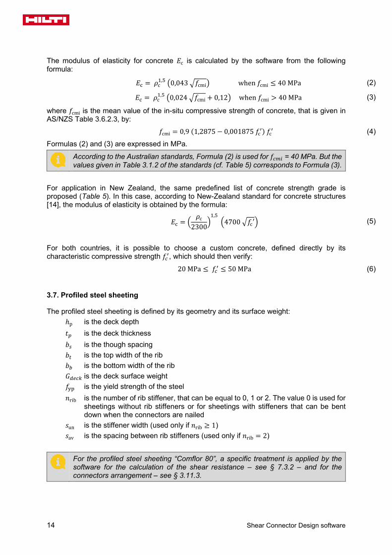
The modulus of elasticity for concrete 𝐸𝐸c is calculated by the software from the following formula:
𝐸𝐸c = 𝜌𝜌c1,5 �0,043 �𝑓𝑓cmi� when 𝑓𝑓cmi ≤ 40 MPa (2)
𝐸𝐸c = 𝜌𝜌c1,5 �0,024 �𝑓𝑓cmi + 0,12� when 𝑓𝑓cmi > 40 MPa (3)
where 𝑓𝑓cmi is the mean value of the in-situ compressive strength of concrete, that is given in AS/NZS Table 3.6.2.3, by:
𝑓𝑓cmi = 0,9 (1,2875 − 0,001875 𝑓𝑓c′) 𝑓𝑓c′ (4)
Formulas (2) and (3) are expressed in MPa.
According to the Australian standards, Formula (2) is used for 𝑓𝑓𝑐𝑐𝑐𝑐𝑐𝑐 = 40 MPa. But the values given in Table 3.1.2 of the standards (cf. Table 5) corresponds to Formula (3).
For application in New Zealand, the same predefined list of concrete strength grade is proposed (Table 5). In this case, according to New-Zealand standard for concrete structures [14], the modulus of elasticity is obtained by the formula:
𝐸𝐸c = �𝜌𝜌c
2300�1,5
�4700 �𝑓𝑓c′� (5)
For both countries, it is possible to choose a custom concrete, defined directly by its characteristic compressive strength 𝑓𝑓𝑐𝑐′, which should then verify:
20 MPa ≤ 𝑓𝑓𝑐𝑐′ ≤ 50 MPa (6)
3.7. Profiled steel sheeting
The profiled steel sheeting is defined by its geometry and its surface weight: ℎp is the deck depth 𝑡𝑡𝑝𝑝 is the deck thickness 𝑏𝑏𝑠𝑠 is the though spacing 𝑏𝑏𝑡𝑡 is the top width of the rib 𝑏𝑏𝑏𝑏 is the bottom width of the rib 𝐺𝐺𝑑𝑑𝑑𝑑𝑐𝑐𝑑𝑑 is the deck surface weight 𝑓𝑓yp is the yield strength of the steel 𝑛𝑛rib is the number of rib stiffener, that can be equal to 0, 1 or 2. The value 0 is used for
sheetings without rib stiffeners or for sheetings with stiffeners that can be bent down when the connectors are nailed
𝑠𝑠un is the stiffener width (used only if 𝑛𝑛rib ≥ 1) 𝑠𝑠av is the spacing between rib stiffeners (used only if 𝑛𝑛rib = 2)
For the profiled steel sheeting “Comflor 80”, a specific treatment is applied by the software for the calculation of the shear resistance – see § 7.3.2 – and for the connectors arrangement – see § 3.11.3.

Technical specifications
Shear Connector Design software 15
According to the requirements of AS/NZS § 3.6.2.7.3, the minimum width of troughs filled with concrete should fulfil the following condition:
min(𝑏𝑏b;𝑏𝑏t) ≥ 50 mm (7)
Following assumptions are considered for rib stiffeners – see Figure 5: The distribution of the stiffeners is assumed to be symmetrical with respect to the
vertical through axis; Stiffeners are assumed to identical and the stiffener arrangement is identical for every
through; The shape of the stiffener is displayed as triangular or trapezoidal according to the
dimensions of the through.
Figure 4: Dimensions of a profiled steel sheeting
a) Rib with one stiffener b) Rib with two stiffeners
Figure 5: Geometry of a rib with one or two stiffeners
The orientation of ribs can be chosen between: Perpendicular to the beam axis. In this case, the decking may be: continuous or not
continuous on the beam; Parallel to the beam axis.
According to AS/NZS 2327 § 2.2.1, the total height above the ribs should fulfil the following conditions:
ℎc = ℎsl − ℎp ≥ ℎc,min (8)
ℎsl ≤ 4 ℎc (9)
where ℎc,min is the minimal thickness of concrete above the main flat surface of the top of the ribs of the sheeting, as defined in Table 6.
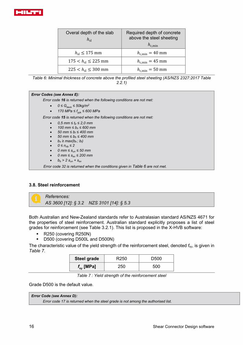
16 Shear Connector Design software
Overal depth of the slab ℎsl
Required depth of concrete above the steel sheeting
ℎc,min
ℎsl ≤ 175 mm ℎc,min = 40 mm
175 < ℎsl ≤ 225 mm ℎc,min = 45 mm
225 < ℎsl ≤ 300 mm ℎc,min = 50 mm
Table 6: Minimal thickness of concrete above the profiled steel sheeting (AS/NZS 2327:2017 Table 2.2.1)
Error Codes (see Annex E): Error code 16 is returned when the following conditions are not met:
• 0 ≤ Gdeck ≤ 50kg/m2 • 170 MPa ≤ fypk ≤ 600 MPa
Error code 15 is returned when the following conditions are not met: • 0,5 mm ≤ tp ≤ 2,0 mm • 100 mm ≤ bs ≤ 600 mm • 50 mm ≤ bt ≤ 400 mm • 50 mm ≤ bb ≤ 400 mm • bs ≥ max(bb ; bt) • 0 ≤ nrib ≤ 2 • 0 mm ≤ sun ≤ 50 mm • 0 mm ≤ sav ≤ 200 mm • bb > 2 sun + sav
Error code 32 is returned when the conditions given in Table 6 are not met.
3.8. Steel reinforcement
References: AS 3600 [12]: § 3.2 NZS 3101 [14]: § 5.3
Both Australian and New-Zealand standards refer to Australasian standard AS/NZS 4671 for the properties of steel reinforcement. Australian standard explicitly proposes a list of steel grades for reinforcement (see Table 3.2.1). This list is proposed in the X-HVB software: R250 (covering R250N) D500 (covering D500L and D500N)
The characteristic value of the yield strength of the reinforcement steel, denoted fsy, is given in Table 7.
Steel grade R250 D500
fsy [MPa] 250 500
Table 7 : Yield strength of the reinforcement steel
Grade D500 is the default value.
Error Code (see Annex D): Error code 17 is returned when the steel grade is not among the authorised list.

Technical specifications
Shear Connector Design software 17
3.9. Shear connection
General parameters
The user can chose the connector type from the following list: X-HVB 40 (used only for solid slabs) X-HVB 50 (used only for solid slabs) X-HVB 80 X-HVB 95 X-HVB 110 X-HVB 125 X-HVB 140
For slabs with profiled steel sheeting, connectors X-HVB 40 and X-HVB 50 are not applicable. Dimensions used in calculations and for drawings of connectors are (see Table 8 for values):
ℎsc is the total height 𝑤𝑤b is the bottom length 𝑤𝑤 is the transverse width
The shear resistance of the connection is defined by: 𝑃𝑃Rk is the characteristic resistance of a single connector 𝑃𝑃Rd is the design resistance of the connector
The values of 𝑃𝑃Rk and 𝑃𝑃Rd are given in Table 8 (according to Table 3 of ETA 15-0876):
X-HVB Characteristic
resistance 𝑃𝑃Rk [kN]
Design resistance 𝑃𝑃Rd [kN]
𝒉𝒉sc mm
𝒘𝒘 mm
𝒘𝒘b mm
40 29 23,2 43 24,3 51
50 29 23,2 52 24,3 50
80 32,5 26 80 24,3 50
95 35 28 95 24,3 50
110 35 28 112,5 24,3 51
125 37,5 30 127,5 25,3 51
140 37,5 30 142,5 25,3 51
Table 8 : Properties of connectors – According to ETA [1]
The values of 𝑃𝑃𝑅𝑅𝑑𝑑 and 𝑃𝑃𝑅𝑅𝑑𝑑 in Table 8 verify the equation: 𝑃𝑃Rd = 𝜙𝜙sc 𝑃𝑃Rk, where 𝜙𝜙sc is defined in § 7.2.
For Comflor 80 steel deck transverse with beam, only X-HVB 140 connectors are possible. Specific values of design resistance are then used (see § 7.3.2).
18 Shear Connector Design software
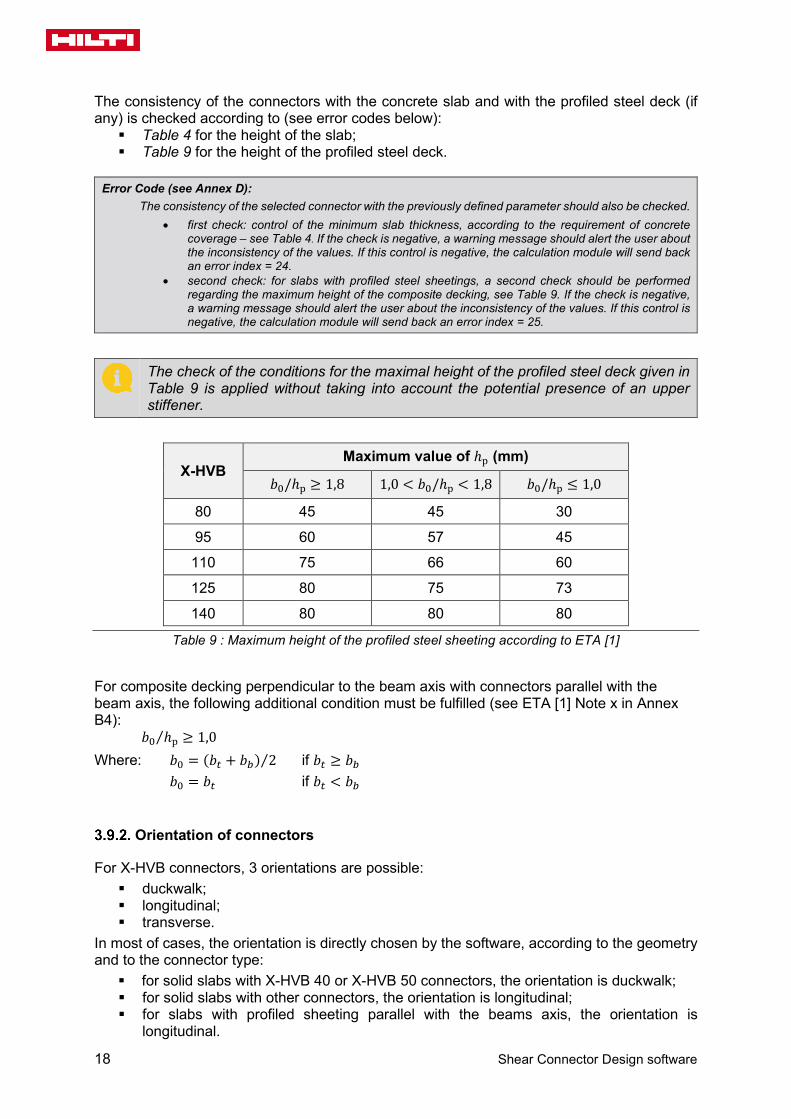
The consistency of the connectors with the concrete slab and with the profiled steel deck (if any) is checked according to (see error codes below): Table 4 for the height of the slab; Table 9 for the height of the profiled steel deck.
Error Code (see Annex D):
The consistency of the selected connector with the previously defined parameter should also be checked. • first check: control of the minimum slab thickness, according to the requirement of concrete
coverage – see Table 4. If the check is negative, a warning message should alert the user about the inconsistency of the values. If this control is negative, the calculation module will send back an error index = 24.
• second check: for slabs with profiled steel sheetings, a second check should be performed regarding the maximum height of the composite decking, see Table 9. If the check is negative, a warning message should alert the user about the inconsistency of the values. If this control is negative, the calculation module will send back an error index = 25.
The check of the conditions for the maximal height of the profiled steel deck given in Table 9 is applied without taking into account the potential presence of an upper stiffener.
X-HVB Maximum value of ℎp (mm)
𝑏𝑏0/ℎp ≥ 1,8 1,0 < 𝑏𝑏0/ℎp < 1,8 𝑏𝑏0/ℎp ≤ 1,0
80 45 45 30
95 60 57 45
110 75 66 60
125 80 75 73
140 80 80 80
Table 9 : Maximum height of the profiled steel sheeting according to ETA [1]
For composite decking perpendicular to the beam axis with connectors parallel with the beam axis, the following additional condition must be fulfilled (see ETA [1] Note x in Annex B4):
𝑏𝑏0 ℎp⁄ ≥ 1,0 Where: 𝑏𝑏0 = (𝑏𝑏𝑡𝑡 + 𝑏𝑏𝑏𝑏) 2⁄ if 𝑏𝑏𝑡𝑡 ≥ 𝑏𝑏𝑏𝑏
𝑏𝑏0 = 𝑏𝑏𝑡𝑡 if 𝑏𝑏𝑡𝑡 < 𝑏𝑏𝑏𝑏
Orientation of connectors
For X-HVB connectors, 3 orientations are possible: duckwalk; longitudinal; transverse.
In most of cases, the orientation is directly chosen by the software, according to the geometry and to the connector type: for solid slabs with X-HVB 40 or X-HVB 50 connectors, the orientation is duckwalk; for solid slabs with other connectors, the orientation is longitudinal; for slabs with profiled sheeting parallel with the beams axis, the orientation is
longitudinal.

Technical specifications
Shear Connector Design software 19
For slabs with profiled steel sheeting transverse to the beam axis, the orientation of connectors must be chosen between: longitudinal with the beam axis; transverse with the beam axis.
Degree of connection
As a plastic design is performed by the software (see § 3.3), the user has to choose the type of connection for the design and the calculation. The three possible choices are: full connection; partial connection; partial connection with a user-defined degree of connection.
When the full connection is chosen, the software calculates the number of connectors in order to be at least equal to the minimum plastic resistance of the slab in compression or the steel profile in tension, so that the full plastic bending resistance of the beam can be obtained. The partial connection choice involves a reduced number of connectors, also assessed by the software, and consequently a reduced bending resistance. The partial connection also implies a greater deformation of the loaded composite beam. For partial connection, the minimum degree of shear connection as given in § 7.5.4 applies. For a partial connection, the user has the possibility (release May 2019) to impose directly a degree of connection (third choice). In this case, it is not necessary to fulfil the minimum requirement on the degree of connection. The relevant warning message is then given in the calculation sheet.
Connection arrangement along the beam
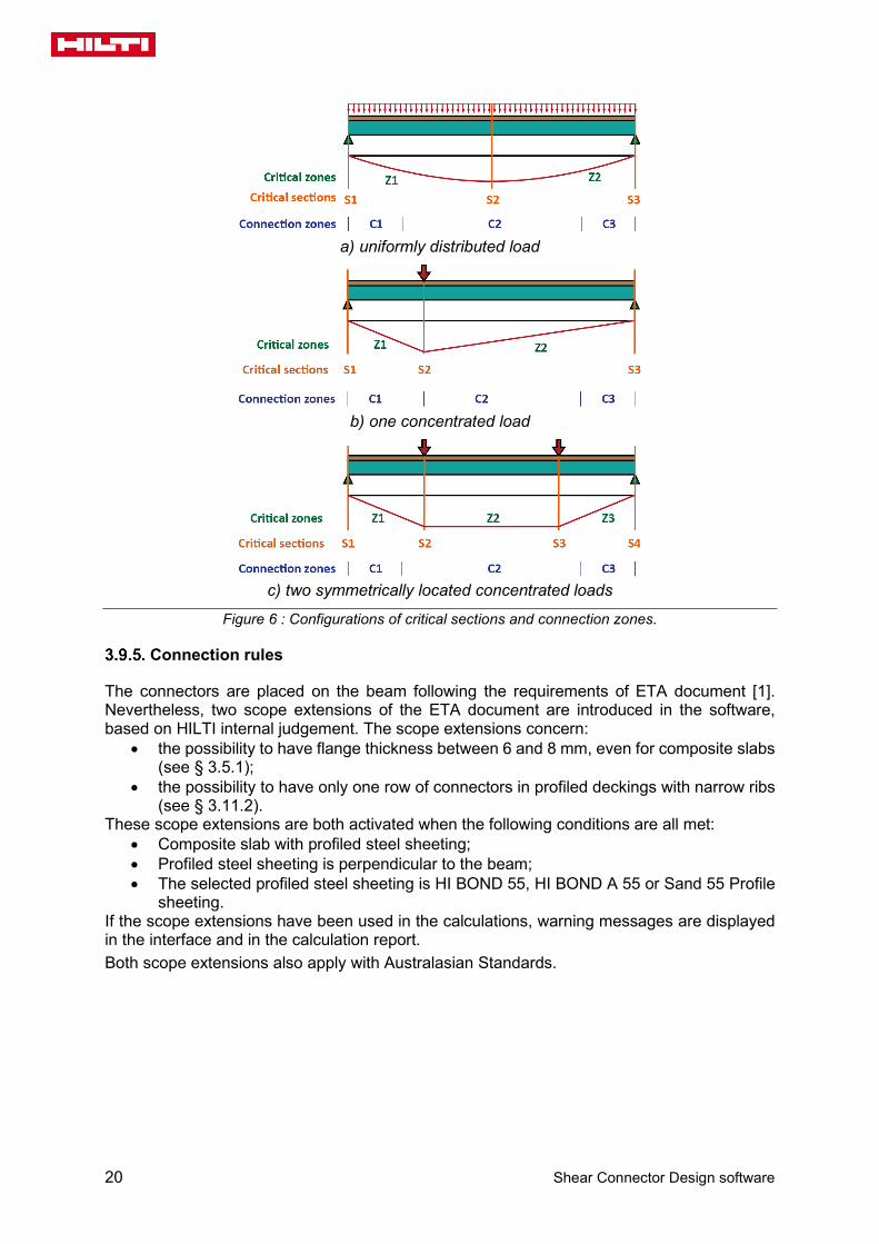
The connection between the slab and the steel profile is automatically designed by the software. Two separate approaches are available according to the type of slabs. For plain slabs or for composite slabs with parallel profiled steel decking, the connection is always assumed to be uniform along the beam. These types of slabs are thus optimised by giving the minimum number of connectors required to fulfil all the design code requirements. For composite slabs with transverse sheetings, the software tries by default to optimise the connection. In order to minimise the number of connectors that are necessary to fulfil all the design code requirements, it might in this case lead to the definition of one to three connection zones with separate connectors arrangement. The following principles are observed for the definition of connection zones: connectors arrangement along a connection zone is always assumed to be uniform; the length of a connection zone is at least equal the one fifth of the beam length; the limit between two adjacent connection zones is always located between a beam
end and the first critical section. Critical sections are defined as follows: cross-sections where the bending moment is maximal; cross-sections where concentrated loads are introduced.
Figure 6 below shows examples of load configuration, critical sections and connections zones. Alternatively, for composite slabs with transverse profiled steel sheeting, the user can impose a uniform arrangement of connectors along the beam (i.e. one single connection zone without optimisation). In this case, the total number of connectors proposed by the software might not be the most economical one.
20 Shear Connector Design software
a) uniformly distributed load
b) one concentrated load
c) two symmetrically located concentrated loads
Figure 6 : Configurations of critical sections and connection zones.
Connection rules
The connectors are placed on the beam following the requirements of ETA document [1]. Nevertheless, two scope extensions of the ETA document are introduced in the software, based on HILTI internal judgement. The scope extensions concern:
• the possibility to have flange thickness between 6 and 8 mm, even for composite slabs (see § 3.5.1);
• the possibility to have only one row of connectors in profiled deckings with narrow ribs (see § 3.11.2).
These scope extensions are both activated when the following conditions are all met: • Composite slab with profiled steel sheeting; • Profiled steel sheeting is perpendicular to the beam; • The selected profiled steel sheeting is HI BOND 55, HI BOND A 55 or Sand 55 Profile
sheeting. If the scope extensions have been used in the calculations, warning messages are displayed in the interface and in the calculation report. Both scope extensions also apply with Australasian Standards.

Technical specifications
Shear Connector Design software 21
3.10. Spacing and positioning of connectors along the beam
According to ETA [1], the maximum centre-to-centre spacing of connectors along the beam shall not exceed four times the total slab thickness or 600 mm:
𝑑𝑑 ≤ min{4 ℎ; 600 mm} (10)
Clause 3.6.4.1 (b) of [7] gives the same requirement.
3.11. Spacing and positioning of connectors perpendicularly to the beam axis
Solid slab with multiple rows of connectors
Two rows Three rows
Figure 7 : Spacing of connectors for solid slabs
The flange width, denoted b, of the steel section must fulfil the following condition: 𝑏𝑏 ≥ 50 (𝑛𝑛𝑟𝑟 − 1) +𝑤𝑤 (11)
Where: 𝑤𝑤 is the transverse width of the connector. This condition may limit the maximum number of connectors in a row – see § 7.5.1.

22 Shear Connector Design software
Slabs with transverse steel decking and connectors parallel to the beam axis
Single row, without rib stiffeners
Figure 8 : Spacing of connectors for slabs with transverse decking and connectors parallel with the
beam (single row).
For the rib width smaller than 𝑏𝑏b < 105 mm, the width at mid-height of the rib must fulfil the following condition:
𝑏𝑏0 ≥ max{𝑤𝑤b + 40 mm; 90 mm} (12)
Where: 𝑤𝑤𝑏𝑏 is the bottom width of the connector. Error Code (see Annex E):
Error code 26 is returned when this condition is not met.
Single row, with rib stiffeners
For sheetings with one rib stiffener (see Figure 9), the following additional condition must be fulfilled:
min{𝑏𝑏𝑏𝑏 ,𝑏𝑏𝑡𝑡} ≥ 2𝑤𝑤𝑏𝑏 + 𝑠𝑠𝑢𝑢𝑢𝑢 (13)
Error Code (see Annex E):
Error code 28 is returned when this condition is not met.
Figure 9 : Transverse sheeting with one rib stiffener and parallel connectors.

Technical specifications
Shear Connector Design software 23
For sheetings with two rib stiffeners, two different configurations are possible: • if the spacing of stiffeners greater or equal to the connector width (𝑠𝑠𝑎𝑎𝑎𝑎 ≥ 𝑤𝑤𝑏𝑏,
see Figure 10), the connectors are located between the stiffeners. • if the spacing of stiffeners is smaller than the connector width (𝑠𝑠𝑎𝑎𝑎𝑎 < 𝑤𝑤𝑏𝑏, see
Figure 11), the connectors are located outside the stiffeners, if the following additional condition is fulfilled:
min{𝑏𝑏𝑏𝑏 ,𝑏𝑏𝑡𝑡} ≥ 2𝑤𝑤𝑏𝑏 + 2𝑠𝑠𝑢𝑢𝑢𝑢 + 𝑠𝑠𝑎𝑎𝑎𝑎 (14)
Error Code (see Annex E): Error code 28 is returned when the two locations of the connectors shown on Figures 8 and 9 are not possible.
Figure 10 : Transverse sheeting with two rib stiffeners and parallel connectors.
Figure 11 : Transverse sheeting with two rib stiffeners and parallel connectors.
Multiple rows, without rib stiffener
Two rows Three rows
Figure 12 : Spacing of connectors for slabs with transverse decking and connectors parallel with the
beam.
24 Shear Connector Design software
The following conditions must be fulfilled:
o For the flange width of the steel section:
𝑏𝑏f ≥ (𝑛𝑛𝑟𝑟 − 1)𝑎𝑎𝑡𝑡 + 𝑤𝑤 (15)
Where: 𝑎𝑎t ≥ 50 mm for profiled decking with 𝑏𝑏0 ℎp⁄ ≥ 1,8 𝑎𝑎t ≥ 100 mm for other decking
This condition may limit the maximum number of connectors in a row – see § 7.5.1.
o For the bottom width of the rib: 𝑏𝑏b ≥ 60 mm (16)
Error Code (see Annex E): Error code 26 is returned when this condition is not met.
Multiple rows, with rib stiffeners
For sheetings with one or two rib stiffeners, the same conditions as the previous case (case of single row) are applied for the case of multiple rows.
Slabs with transverse steel decking and connectors transverse to the beam axis
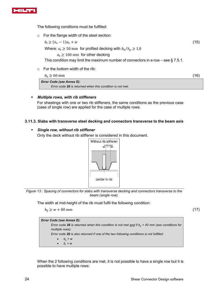
Single row, without rib stiffener Only the deck without rib stiffener is considered in this document.
Figure 13 : Spacing of connectors for slabs with transverse decking and connectors transverse to the
beam (single row).
The width at mid-height of the rib must fulfil the following condition: 𝑏𝑏0 ≥ 𝑤𝑤 + 80 mm (17)
Error Code (see Annex E):
Error code 26 is returned when this condition is not met and if bb < 40 mm (see conditions for multiple rows). Error code 26 is also returned if one of the two following conditions is not fulfilled:
• bb > w • br > w
When the 2 following conditions are met, it is not possible to have a single row but it is possible to have multiple rows:

Technical specifications
Shear Connector Design software 25
𝑏𝑏0 < 𝑤𝑤 + 80 mm 𝑏𝑏b ≥ 40 mm
(18)
In this case, the calculation module starts the design process by considering 2 connectors in a row (see § 7.5.1). The minimum width of ribs for one connector can be reduced when the relevant software option is activated (see § 3.9.5). This option extended the scope of the ETA report [1]. In this case, following conditions are checked:
𝑏𝑏t ≥ 30 mm 𝑏𝑏b ≥ 30 mm
(19)
Single row, with rib stiffeners For sheetings with one rib stiffener (see Figure 14), according to ETA report [1] case b, only the following condition must be fulfilled:
min{𝑏𝑏𝑏𝑏 ,𝑏𝑏𝑡𝑡} ≥ 2𝑤𝑤 + 𝑠𝑠𝑢𝑢𝑢𝑢 (20)
Error Code (see Annex E):
Error code 28 is returned when this condition is not met.
Figure 14 : Transverse sheeting with one rib stiffener and transverse connectors.
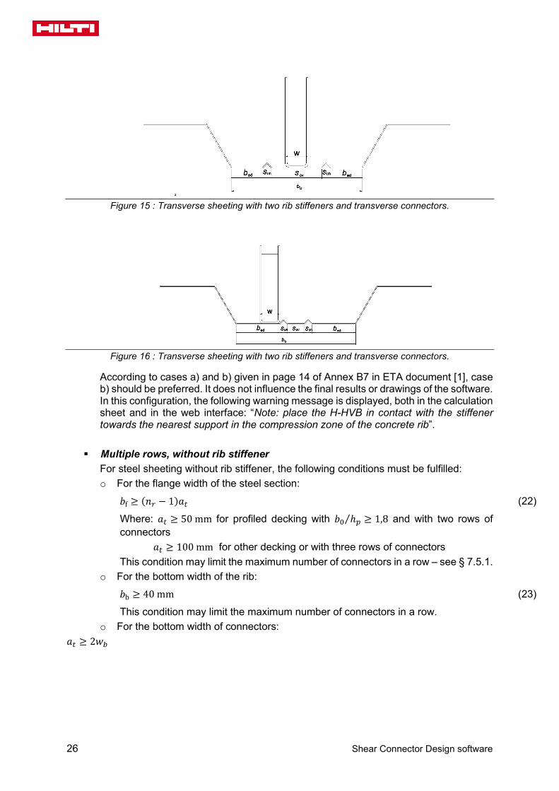
According to cases a) and b) given in page 14 of Annex B7 in ETA report [1], case b) should be preferred. It does not influence the final results or drawings of the software. In this configuration, the following warning message is displayed, both in the calculation sheet and in the web interface: “Note: place the H-HVB in contact with the stiffener towards the nearest support in the compression zone of the concrete rib”. For sheetings with two rib stiffeners, two different locations are possible, according to the spacing between stiffeners:
• if 𝑠𝑠𝑎𝑎𝑎𝑎 ≥ 𝑤𝑤 (see Figure 15), the connector is placed in the rib axis. • if 𝑠𝑠𝑎𝑎𝑎𝑎 < 𝑤𝑤 (see Figure 16), the connector is placed outside the two ribs, if the
following condition is fulfilled:
min{𝑏𝑏𝑏𝑏,𝑏𝑏𝑡𝑡} ≥ 2𝑤𝑤 + 2𝑠𝑠𝑢𝑢𝑢𝑢 + 𝑠𝑠𝑎𝑎𝑎𝑎 (21)
Error Code (see Annex E): Error code 28 is returned when the previous conditions are not met.
26 Shear Connector Design software
Figure 15 : Transverse sheeting with two rib stiffeners and transverse connectors.
Figure 16 : Transverse sheeting with two rib stiffeners and transverse connectors.
According to cases a) and b) given in page 14 of Annex B7 in ETA document [1], case b) should be preferred. It does not influence the final results or drawings of the software. In this configuration, the following warning message is displayed, both in the calculation sheet and in the web interface: “Note: place the H-HVB in contact with the stiffener towards the nearest support in the compression zone of the concrete rib”.
Multiple rows, without rib stiffener For steel sheeting without rib stiffener, the following conditions must be fulfilled: o For the flange width of the steel section:
𝑏𝑏f ≥ (𝑛𝑛𝑟𝑟 − 1)𝑎𝑎𝑡𝑡 (22)
Where: 𝑎𝑎𝑡𝑡 ≥ 50 mm for profiled decking with 𝑏𝑏0 ℎ𝑝𝑝⁄ ≥ 1,8 and with two rows of connectors
𝑎𝑎𝑡𝑡 ≥ 100 mm for other decking or with three rows of connectors This condition may limit the maximum number of connectors in a row – see § 7.5.1.
o For the bottom width of the rib: 𝑏𝑏b ≥ 40 mm (23)
This condition may limit the maximum number of connectors in a row. o For the bottom width of connectors:
𝑎𝑎𝑡𝑡 ≥ 2𝑤𝑤𝑏𝑏

Technical specifications
Shear Connector Design software 27
Figure 17 : Spacing of connectors for slabs with transverse decking and connectors transverse to the
beam (multiple rows).
Multiple rows, with rib stiffeners
For decks with rib stiffeners, the same conditions as the previous case (single row) are applied for the case of multiple rows. For Comflor 80 deck, when 𝑛𝑛𝑟𝑟 = 3 or 4, the condition (23) is used with 𝑎𝑎𝑡𝑡 = 65 𝑚𝑚𝑚𝑚 (according to [2]).
Figure 18 : Specific positioning of 4 transverse connectors with Comflor 80 deck
28 Shear Connector Design software
Slabs with parallel steel decking and connectors parallel to the beam axis
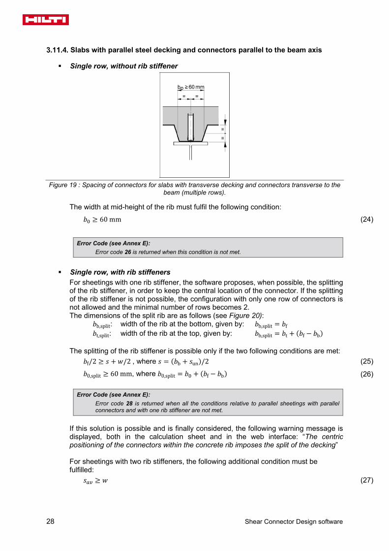
Single row, without rib stiffener
Figure 19 : Spacing of connectors for slabs with transverse decking and connectors transverse to the
beam (multiple rows).
The width at mid-height of the rib must fulfil the following condition:
𝑏𝑏0 ≥ 60 mm (24)
Error Code (see Annex E): Error code 26 is returned when this condition is not met.
Single row, with rib stiffeners
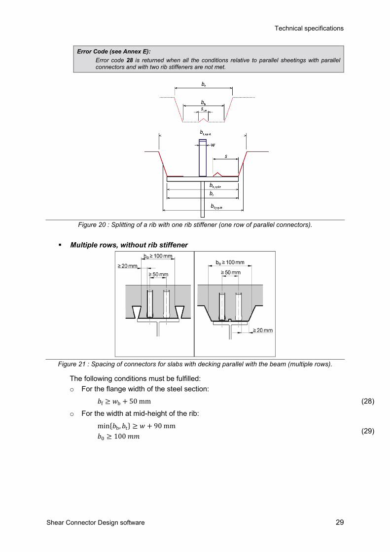
For sheetings with one rib stiffener, the software proposes, when possible, the splitting of the rib stiffener, in order to keep the central location of the connector. If the splitting of the rib stiffener is not possible, the configuration with only one row of connectors is not allowed and the minimal number of rows becomes 2. The dimensions of the split rib are as follows (see Figure 20):
𝑏𝑏b,split: width of the rib at the bottom, given by: 𝑏𝑏b,split = 𝑏𝑏f 𝑏𝑏t,split: width of the rib at the top, given by: 𝑏𝑏b,split = 𝑏𝑏t + (𝑏𝑏f − 𝑏𝑏b)
The splitting of the rib stiffener is possible only if the two following conditions are met:
𝑏𝑏f/2 ≥ 𝑠𝑠 + 𝑤𝑤/2 , where 𝑠𝑠 = (𝑏𝑏b + 𝑠𝑠un)/2 (25)
𝑏𝑏0,split ≥ 60 mm, where 𝑏𝑏0,split = 𝑏𝑏0 + (𝑏𝑏f − 𝑏𝑏b) (26)
Error Code (see Annex E): Error code 28 is returned when all the conditions relative to parallel sheetings with parallel connectors and with one rib stiffener are not met.
If this solution is possible and is finally considered, the following warning message is displayed, both in the calculation sheet and in the web interface: “The centric positioning of the connectors within the concrete rib imposes the split of the decking” For sheetings with two rib stiffeners, the following additional condition must be fulfilled:
𝑠𝑠𝑎𝑎𝑎𝑎 ≥ 𝑤𝑤 (27)
Technical specifications
Shear Connector Design software 29
Error Code (see Annex E): Error code 28 is returned when all the conditions relative to parallel sheetings with parallel connectors and with two rib stiffeners are not met.
Figure 20 : Splitting of a rib with one rib stiffener (one row of parallel connectors).
Multiple rows, without rib stiffener
Figure 21 : Spacing of connectors for slabs with decking parallel with the beam (multiple rows).
The following conditions must be fulfilled: o For the flange width of the steel section:
𝑏𝑏f ≥ 𝑤𝑤b + 50 mm (28) o For the width at mid-height of the rib:
min{𝑏𝑏b,𝑏𝑏t} ≥ 𝑤𝑤 + 90 mm 𝑏𝑏0 ≥ 100 𝑚𝑚𝑚𝑚
(29)

30 Shear Connector Design software
Multiple row, with rib stiffeners For sheetings with one rib stiffener, the following conditions must be fulfilled: o For the flange width of the steel section:
𝑏𝑏f ≥ 𝑤𝑤 + max{50 mm, 𝑠𝑠un + 𝑤𝑤} (30)
o For the width of the rib: min{𝑏𝑏b,𝑏𝑏t} ≥ 𝑤𝑤 + 40 mm + max{50 mm, 𝑠𝑠un + 𝑤𝑤} (31)
𝑏𝑏0 ≥ 100 mm (32)
Error Code (see Annex E): Error code 28 is returned when all the conditions relative to parallel sheetings with parallel connectors and with one rib stiffener are not met.
For sheetings with two rib stiffeners, two configurations are possible:
• if 𝑠𝑠av ≥ 𝑤𝑤 + 50 mm (see Figure 22), the connectors are located between the stiffeners. The same conditions as the case of sheetings without rib stiffener must be fulfilled.
Figure 22 : Sheeting with two rib stiffeners and connectors parallel with the beam (multiple rows).
• if 𝑠𝑠av < 𝑤𝑤 + 50 mm, the connectors are located outside the stiffeners, if the following conditions are fulfilled:
• For the flange width of the steel section: 𝑏𝑏f ≥ 𝑤𝑤 + max{50 mm −𝑤𝑤, 𝑠𝑠av + 2 𝑠𝑠un} (33)
• For the width of the rib: min{𝑏𝑏b,𝑏𝑏t} ≥ 2 𝑤𝑤 + 40 mm + max{50 mm −𝑤𝑤, 𝑠𝑠av + 2 𝑠𝑠un} (34)
𝑏𝑏0 ≥ 100 mm (35)
Error Code (see Annex E):
Error code 28 is returned when all the conditions relatives to parallel sheetings with parallel connectors and with two rib stiffeners are not met.
Figure 23 : Sheeting with two rib stiffeners and connectors parallel with the beam (multiple rows).

Technical specifications
Shear Connector Design software 31
Slabs with duckwalk positioning (X-HVB-40 and 50) – single row only
The minimum spacing between 2 connectors is 100 mm. This condition may limit the maximum number of connection rows – see § 7.5.1.
3.12. Loads
General definitions
The calculation module allows the user to define elementary variable load cases (according to AS/NZS 1170.1) that are used in the combinations of actions for ULS or SLS (according to AS/NZS 1170.0). Only gravity loads are considered (downwards). Up to four elementary load cases are considered within these specifications:
o One permanent load case, denoted G o One live load during construction stage, denoted Qc o Up to two live load cases during the final stage, Q1 and Q2
The dead weight of the steel profile and concrete slab is automatically calculated and added in the permanent load case. It can be overwritten by the user. For each load case, it is possible to define: One uniformly distributed surface load, denoted qsurf Up to ten point loads along the beam, denoted Pi Up to three patch loads along the beam, denoted qi
For the permanent load case G, 2 surface loads could be defined: the first one associated to the dead loads of the beam and acting during the
construction phase; qsurf,d is by default automatically calculated by the program but may be modified by the user;
the second one qsurf,u associated to additional permanent loads, acting only during the composite stage.
For live load construction stage live loads case, only the uniformly distributed surface load can be defined in the UI. For the final stage live load Q1, only the uniformly distributed surface load can be defined in the UI.
Specific treatment of surface loads
For the check of the beam, and especially the calculation of internal forces, the surface load of each load case is derived either as uniformly distributed loads or as a set of point loads. For a “secondary interior beam”, a linear uniformly distributed load along the beam is derived:
𝑞𝑞𝑙𝑙𝑐𝑐𝑢𝑢 = 𝑞𝑞𝑠𝑠𝑢𝑢𝑟𝑟𝑠𝑠 (𝑏𝑏1 + 𝑏𝑏2) 2⁄ (36)
For a “secondary edge beam”, this relation is replaced by:
𝑞𝑞𝑙𝑙𝑐𝑐𝑢𝑢 = 𝑞𝑞𝑠𝑠𝑢𝑢𝑟𝑟𝑠𝑠 (𝑏𝑏1 + 𝑏𝑏2/2) (37)
For a “primary beam” defined without secondary beams, the same 2 previous equations are applied, considering the option intermediate or edge beam.

32 Shear Connector Design software
For a “primary beam” defined with one or several secondary beams, the surface load applied on the concrete slab (𝑞𝑞𝑠𝑠𝑢𝑢𝑟𝑟𝑠𝑠) is transferred by secondary beams to the primary beam. Considering a “primary intermediate beam”, a point load is derived at the location of the i-th secondary beam (note: no secondary beams in the first version of the HVB software):
𝑃𝑃𝑠𝑠,𝑐𝑐 = �𝑞𝑞𝑠𝑠𝑢𝑢𝑟𝑟𝑠𝑠 (𝐿𝐿𝑐𝑐+1 − 𝐿𝐿𝑐𝑐−1) 2⁄ � (𝑏𝑏1 + 𝑏𝑏2) 2⁄ (38)
Where: 𝐿𝐿0 = 0 and 𝐿𝐿𝑢𝑢𝑠𝑠+1 = 𝐿𝐿 For the global equilibrium of the applied forces, point loads are also applied at both supports:
𝑃𝑃𝑠𝑠,0 = �𝑞𝑞𝑠𝑠𝑢𝑢𝑟𝑟𝑠𝑠 𝐿𝐿 (2(𝑛𝑛𝑠𝑠 + 1))⁄ � (𝑏𝑏1 + 𝑏𝑏2) 2⁄ (39)
For a “primary edge beam”, these 2 equations are replaced respectively by the 2 following ones:
𝑃𝑃𝑠𝑠,𝑐𝑐 = �𝑞𝑞𝑠𝑠𝑢𝑢𝑟𝑟𝑠𝑠 (𝐿𝐿𝑐𝑐+1 − 𝐿𝐿𝑐𝑐−1) 2⁄ �(𝑏𝑏1 + 𝑏𝑏2/2) (40)
𝑃𝑃𝑠𝑠,0 = �𝑞𝑞𝑠𝑠𝑢𝑢𝑟𝑟𝑠𝑠 𝐿𝐿 (2(𝑛𝑛𝑠𝑠 + 1))⁄ �(𝑏𝑏1 + 𝑏𝑏2/2) (41)
Automatic dead load assessment
The dead loads of the beam, of the potential secondary beams, of the slab and of the potential steel profiled sheetings are automatically included in the permanent load case G. The dead load of the beam is treated as an uniformly surface load defined by:
for interior beams : 𝑞𝑞𝑠𝑠𝑢𝑢𝑟𝑟𝑠𝑠,d = 2𝑘𝑘 𝜌𝜌s 𝐴𝐴𝑏𝑏1 + 𝑏𝑏2
(42)
for edge beams : 𝑞𝑞𝑠𝑠𝑢𝑢𝑟𝑟f,d = 2𝑘𝑘 𝜌𝜌s 𝐴𝐴
2 𝑏𝑏1 + 𝑏𝑏2 (43)
where: 𝑘𝑘 is the gravity constant: g = 9,81 m/s2 𝜌𝜌s: see § 3.5.2 𝐴𝐴 is the area of the beam profile (see Annex A)
Technical specifications
Shear Connector Design software 33
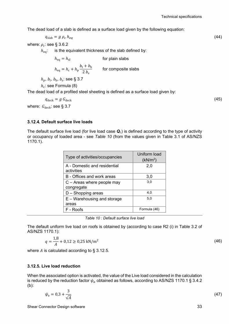
The dead load of a slab is defined as a surface load given by the following equation:
𝑞𝑞slab = 𝑘𝑘 𝜌𝜌𝑐𝑐 ℎ𝑑𝑑𝑒𝑒 (44)
where: 𝜌𝜌c: see § 3.6.2 ℎeq: is the equivalent thickness of the slab defined by:
ℎeq = ℎsl for plain slabs
ℎeq = ℎc + ℎp𝑏𝑏t + 𝑏𝑏b
2 𝑏𝑏s for composite slabs
ℎp, 𝑏𝑏t, 𝑏𝑏b, 𝑏𝑏s: see § 3.7 ℎc: see Formula (8)
The dead load of a profiled steel sheeting is defined as a surface load given by:
𝑞𝑞deck = 𝑘𝑘 𝐺𝐺deck (45)
where: 𝐺𝐺deck: see § 3.7
Default surface live loads
The default surface live load (for live load case Q1) is defined according to the type of activity or occupancy of loaded area - see Table 10 (from the values given in Table 3.1 of AS/NZS 1170.1).
Type of activities/occupancies Uniform load
(kN/m2) A - Domestic and residential activities
2,0
B - Offices and work areas 3,0 C – Areas where people may congregate
3,0
D – Shopping areas 4,0
E – Warehousing and storage areas
5,0
F - Roofs Formula (46)
Table 10 : Default surface live load
The default uniform live load on roofs is obtained by (according to case R2 (i) in Table 3.2 of AS/NZS 1170.1):
𝑞𝑞 =1,8𝐴𝐴
+ 0,12 ≥ 0,25 kN/m2 (46)
where 𝐴𝐴 is calculated according to § 3.12.5.
Live load reduction
When the associated option is activated, the value of the Live load considered in the calculation is reduced by the reduction factor 𝜓𝜓𝑎𝑎 obtained as follows, according to AS/NZS 1170.1 § 3.4.2 (b):
𝜓𝜓a = 0,3 +3√𝐴𝐴
(47)

34 Shear Connector Design software
but : 0,5 ≤ 𝜓𝜓𝑎𝑎 ≤ 1,0 where: A is the sum of the areas supported by the composite beam (in m2), given by:
for interior beams: A = L (b1 + b2)/2 for edge beams: A = L (b1 + b2/2)
4. COMBINATIONS OF LOADS
4.1. Ultimate Limit States (ULS)
The ULS combinations are automatically generated according to AS/NZS 1170.0 §4.2.2 as follows:
• when only one live load is defined
1,35 𝐺𝐺 1,2 𝐺𝐺 + 1,5 𝑄𝑄
(48)
• when two live loads are defined (second interpretation of the standard [7])
1,35 𝐺𝐺 1,2 𝐺𝐺 + 1,5 𝑄𝑄1 + 1,5 𝑄𝑄2
(49)
It is possible for the User to modify the combinations factors.
For the construction stage, if the load case 𝑄𝑄c has been defined, following ULS combinations is considered:
1,35 𝐺𝐺 1,2 𝐺𝐺 + 1,5 𝑄𝑄c
(50)
4.2. Serviceability Limit States (SLS)
The SLS combinations for the verification of deflections are automatically generated as follows, when only one live loads case is defined:
total deflection: 𝐺𝐺 + 𝑄𝑄1 incremental deflection: 𝑝𝑝𝐺𝐺 𝐺𝐺 + 1,0 𝑄𝑄1
(51)
When two live loads cases are defined:
total deflection: 𝐺𝐺 + 𝑄𝑄1 + 𝑄𝑄2 incremental deflection: 𝑝𝑝𝐺𝐺 𝐺𝐺 + 1,0 (𝑄𝑄1 + 𝑄𝑄2)
(52)
By default, the fraction of permanent loads is: 𝑝𝑝𝐺𝐺 = 0. The combinations for the calculation of the fundamental natural frequency are automatically generated as follows:

Technical specifications
Shear Connector Design software 35
One live loads case: 𝐺𝐺 + 𝑝𝑝𝑄𝑄𝑄𝑄1 Two live loads cases: 𝐺𝐺 + 𝑝𝑝𝑄𝑄 (𝑄𝑄1 + 𝑄𝑄2)
(53)
By default, the fraction of live loads is: 𝑝𝑝𝑄𝑄 = 0,20.
It is possible for the User to modify the fraction of the permanent load used for the incremental deflection check and the fraction of live loads used for the calculation of the fundamental natural frequency.
5. GLOBAL ANALYSIS
5.1. Design points
Shear forces, bending moments and deflections are calculated at design points along the beam. Initially, design points are regularly spaced along the beam with the spacing of 𝐿𝐿 50⁄ between two consecutive design points. An additional design point may be added at each point load if the last one is not located at existing design points.
5.2. Critical sections
ULS verifications are carried out at critical sections (AS/NZS § 3.5.3) where: The bending moment is maximum; At supports; At point load locations.
5.3. Calculation of internal forces, moments and deflections for basic loads
The calculation of internal forces and moments is described hereafter for each individual point load and patch load. Any surface load will be considered with these two methods according to § 3.12.2.
Point load
P
xP
x
L
Figure 24 : Point load.
The reactions at supports are calculated by: 𝑅𝑅𝐿𝐿 = −𝑃𝑃 (𝐿𝐿 − 𝑥𝑥𝑃𝑃) / 𝐿𝐿 at the Left support 𝑅𝑅𝑅𝑅 = −𝑃𝑃 𝑥𝑥𝑃𝑃 / 𝐿𝐿 at the Right support where: P is the applied point load;
36 Shear Connector Design software
xP is the abscissa of the point load from the left support The shear force in a section located at the abscissa x is calculated by: 𝑉𝑉(𝑥𝑥) = 𝑅𝑅𝐿𝐿 if 𝑥𝑥 < 𝑥𝑥𝑃𝑃 𝑉𝑉(𝑥𝑥) = −𝑅𝑅𝑅𝑅 if 𝑥𝑥 > 𝑥𝑥𝑃𝑃 The bending moment in a section located at the abscissa x is calculated by: 𝑀𝑀(𝑥𝑥) = −𝑅𝑅𝐿𝐿𝑥𝑥 if 𝑥𝑥 < 𝑥𝑥𝑃𝑃 𝑀𝑀(𝑥𝑥) = −𝑅𝑅𝑅𝑅(𝐿𝐿 − 𝑥𝑥) if 𝑥𝑥 > 𝑥𝑥𝑃𝑃 The deflection in a section located at the abscissa x is calculated by: 𝑤𝑤(𝑥𝑥) = 𝐹𝐹
6𝐸𝐸𝐸𝐸𝐿𝐿[𝐿𝐿2 − (𝐿𝐿 − 𝑥𝑥𝑃𝑃)2 − 𝑥𝑥2](𝐿𝐿 − 𝑥𝑥𝑃𝑃)𝑥𝑥 if 𝑥𝑥 < 𝑥𝑥𝑃𝑃
𝑤𝑤(𝑥𝑥) = 𝐹𝐹6𝐸𝐸𝐸𝐸𝐿𝐿
[𝐿𝐿2 − (𝐿𝐿 − 𝑥𝑥)2 − 𝑥𝑥𝑃𝑃2](𝐿𝐿 − 𝑥𝑥)𝑥𝑥𝑃𝑃 if 𝑥𝑥 > 𝑥𝑥𝑃𝑃
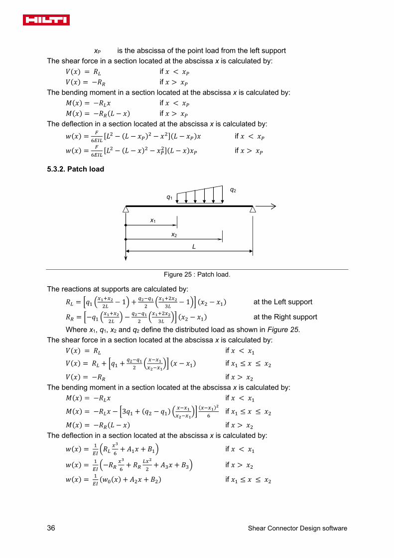
Patch load
x1
q1 q2
x2
L
Figure 25 : Patch load.
The reactions at supports are calculated by:
𝑅𝑅𝐿𝐿 = �𝑞𝑞1 �𝑥𝑥1+𝑥𝑥22𝐿𝐿
− 1� + 𝑒𝑒2−𝑒𝑒12
�𝑥𝑥1+2𝑥𝑥23𝐿𝐿
− 1�� (𝑥𝑥2 − 𝑥𝑥1) at the Left support
𝑅𝑅𝑅𝑅 = �−𝑞𝑞1 �𝑥𝑥1+𝑥𝑥22𝐿𝐿
� − 𝑒𝑒2−𝑒𝑒12
�𝑥𝑥1+2𝑥𝑥23𝐿𝐿
�� (𝑥𝑥2 − 𝑥𝑥1) at the Right support
Where x1, q1, x2 and q2 define the distributed load as shown in Figure 25. The shear force in a section located at the abscissa x is calculated by: 𝑉𝑉(𝑥𝑥) = 𝑅𝑅𝐿𝐿 if 𝑥𝑥 < 𝑥𝑥1
𝑉𝑉(𝑥𝑥) = 𝑅𝑅𝐿𝐿 + �𝑞𝑞1 + 𝑒𝑒2−𝑒𝑒12
� 𝑥𝑥−𝑥𝑥1𝑥𝑥2−𝑥𝑥1
�� (𝑥𝑥 − 𝑥𝑥1) if 𝑥𝑥1 ≤ 𝑥𝑥 ≤ 𝑥𝑥2
𝑉𝑉(𝑥𝑥) = −𝑅𝑅𝑅𝑅 if 𝑥𝑥 > 𝑥𝑥2 The bending moment in a section located at the abscissa x is calculated by: 𝑀𝑀(𝑥𝑥) = −𝑅𝑅𝐿𝐿𝑥𝑥 if 𝑥𝑥 < 𝑥𝑥1
𝑀𝑀(𝑥𝑥) = −𝑅𝑅𝐿𝐿𝑥𝑥 − �3𝑞𝑞1 + (𝑞𝑞2 − 𝑞𝑞1) � 𝑥𝑥−𝑥𝑥1𝑥𝑥2−𝑥𝑥1
�� (𝑥𝑥−𝑥𝑥1)2
6 if 𝑥𝑥1 ≤ 𝑥𝑥 ≤ 𝑥𝑥2
𝑀𝑀(𝑥𝑥) = −𝑅𝑅𝑅𝑅(𝐿𝐿 − 𝑥𝑥) if 𝑥𝑥 > 𝑥𝑥2 The deflection in a section located at the abscissa x is calculated by:
𝑤𝑤(𝑥𝑥) = 1𝐸𝐸𝐸𝐸�𝑅𝑅𝐿𝐿
𝑥𝑥3
6+ 𝐴𝐴1𝑥𝑥 + 𝐵𝐵1� if 𝑥𝑥 < 𝑥𝑥1
𝑤𝑤(𝑥𝑥) = 1𝐸𝐸𝐸𝐸�−𝑅𝑅𝑅𝑅
𝑥𝑥3
6+ 𝑅𝑅𝑅𝑅
𝐿𝐿𝑥𝑥2
2+ 𝐴𝐴3𝑥𝑥 + 𝐵𝐵3� if 𝑥𝑥 > 𝑥𝑥2
𝑤𝑤(𝑥𝑥) = 1𝐸𝐸𝐸𝐸
(𝑤𝑤0(𝑥𝑥) + 𝐴𝐴2𝑥𝑥 + 𝐵𝐵2) if 𝑥𝑥1 ≤ 𝑥𝑥 ≤ 𝑥𝑥2

Technical specifications
Shear Connector Design software 37
Where: 𝑝𝑝 = (𝑞𝑞2 − 𝑞𝑞1)/(𝑥𝑥2 − 𝑥𝑥1)
𝑤𝑤0(𝑥𝑥) = 𝑅𝑅𝐿𝐿𝑥𝑥3
6− 1
120(𝑥𝑥 − 𝑥𝑥1)4[5𝑞𝑞1 + 𝑝𝑝(𝑥𝑥 − 𝑥𝑥1)]
𝐵𝐵1 = 0
𝐵𝐵2 = 𝑅𝑅𝐿𝐿𝑥𝑥13
3+𝑤𝑤0′(𝑥𝑥1)𝑥𝑥1 − 𝑤𝑤0(𝑥𝑥1)
𝐵𝐵3 = 𝑤𝑤0(𝑥𝑥2) + 𝐵𝐵2 − �−𝑅𝑅𝑅𝑅𝑥𝑥23
3+ 𝑅𝑅𝑅𝑅𝐿𝐿
𝑥𝑥22
2+𝑤𝑤0′(𝑥𝑥2)𝑥𝑥2�
𝐴𝐴3 = 1𝐿𝐿�𝑅𝑅𝑅𝑅
𝐿𝐿3
3− 𝐵𝐵3�
𝐴𝐴2 = 𝐴𝐴3 − �𝑤𝑤0′(𝑥𝑥2) − 𝑅𝑅𝑅𝑅𝑥𝑥22
2+ 𝑅𝑅𝑅𝑅𝐿𝐿𝑥𝑥2�
𝐴𝐴1 = 𝑤𝑤0′(𝑥𝑥1) + 𝐴𝐴2 + 𝑅𝑅𝐿𝐿𝑥𝑥12
2
5.4. Precamber
In the previous formulas for the calculation of the deflection at each design cross-section, the second moment of area will be calculated for the composite stage considering the following assumptions: When a precambering has been defined by the user, the following deflection is added in each cross-section:
𝑤𝑤0,𝑥𝑥 = −4 𝑤𝑤0𝑥𝑥𝐿𝐿
�1 −𝑥𝑥𝐿𝐿� (54)
Where: w0 is the precambering. The precambering deflection is not considered when assessing the deflections used for the natural frequency.
5.5. Influence of the connectors slip
References: AS/NZS 2327 § 3.5.5
The influence of the connector slip on the beam deflection is dealt with according to the simplified method provided by Formulas 3.10.3.2 (1) and (2) of AS/NZS 2327. For beams with partial connection, all deflections are increased by one of the following factor:
for propped beams during construction : 𝑘𝑘pc = 1 + 0,5 (1 − 𝛽𝛽cr 𝛽𝛽) �𝛿𝛿s
𝛿𝛿c− 1� (55)
for unpropped beams during construction : 𝑘𝑘pc = 1 + 0,3 (1 − 𝛽𝛽cr 𝛽𝛽) �𝛿𝛿s
𝛿𝛿c− 1� (56)
where: 𝛽𝛽 is the degree of connection of the beam (see § 7.5.6); 𝛽𝛽cr is the creep deflection coefficient: 𝛽𝛽cr = 1; 𝛿𝛿s is the maximum deflection of the beam considering only the steel beam flexural stiffness; 𝛿𝛿c is the maximum deflection of the beam considering the composite action with a full connection.

38 Shear Connector Design software
6. VERIFICATIONS AT THE CONSTRUCTION STAGE
6.1. General
Verifications at the construction stage are carried out only when the beam is unpropped. The beam is checked for Ultimate State of Strength, which include the following verifications: Section bending moment capacity Member capacity (resistance to lateral torsional buckling) Web resistance to vertical shear Interaction of vertical shear and bending
All verification criteria (except for LTB resistance) are calculated at each design point along the beam. In the calculation report, the maximum value of each criterion will be displayed. No SLS checks apply at construction stage. The software will nevertheless provide the deflection under SLS combination.
6.2. Strength verifications
Capacity factors
References: AS 4100 [11]: Table 3.4 NZS 3404 [13]: Table 3.3
Design capacity for § Capacity factor
Bending moment capacity 6.2.3 𝜙𝜙M = 0,9
Member capacity 6.2.4 𝜙𝜙Mb = 0,9
Shear resistance of the web 6.2.5 𝜙𝜙v = 0,9
Shear and bending interaction 6.2.6 𝜙𝜙vm = 0,9
Table 11: Capacity factors
These values are predefined and it is possible to modify them in the settings of the project.

Technical specifications
Shear Connector Design software 39
Section slenderness
References: AS 4100 [11]: § 5.2.2 NZS 3404 [13]: § 5.2.2
The slenderness of the upper flange (in uniform compression) is obtained by:
𝜆𝜆ef =(𝑏𝑏f − 𝑡𝑡w)/2
𝑡𝑡f �
𝑓𝑓𝑦𝑦250
(57)
The section plasticity and yield slenderness limits (𝜆𝜆efp and 𝜆𝜆efy respectively) of the flange are given in Table 12 (from Table 5.2 of [11] for Australia and from Table 5.2 of [13] for New Zealand).
Type of profile Plasticity limit 𝜆𝜆efp Yield limit 𝜆𝜆efy
Profiles from the database (hot-rolled) 9 16
Custom profiles (built-up heavily welded) 8 14
Table 12: Slenderness limits for flanges acc. to Australian and New Zealand standards
Differently from Eurocodes, the slenderness is assessed by taking into account the clear width of the panel from the face of the supporting plate. It thus includes the fillets.
The slenderness of the web (bending, with compression at one edge and tension at the other) is defined by:
𝜆𝜆ew =ℎt − 2 𝑡𝑡f
𝑡𝑡w �
𝑓𝑓𝑦𝑦250
(58)
The section plasticity and yield slenderness limits (𝜆𝜆ewp and 𝜆𝜆ewy respectively) of the web are given in Table 13.
Type of profile Plasticity limit 𝜆𝜆ewp
Yield limit 𝜆𝜆ewy
from Table 5.2 of [11] for Australia
all sections 82 115
from Table 5.2 of [13] for New Zealand
all section 82 180 (*) (*) acc. to note (5) in Table 5.2 of [13] for doubly symmetric I section
Table 13: Slenderness limits for flanges acc. to Australian and New Zealand standards
The section slenderness 𝜆𝜆s and the slenderness limits 𝜆𝜆sp and 𝜆𝜆sy are defined as follows:
if 𝜆𝜆ew
𝜆𝜆ewy≥
𝜆𝜆ef
𝜆𝜆efy
𝜆𝜆s = 𝜆𝜆ew 𝜆𝜆sp = 𝜆𝜆ewp

40 Shear Connector Design software
𝜆𝜆sy = 𝜆𝜆ewy
if 𝜆𝜆ew
𝜆𝜆ewy<
𝜆𝜆ef
𝜆𝜆efy
𝜆𝜆s = 𝜆𝜆ef 𝜆𝜆sp = 𝜆𝜆efp 𝜆𝜆sy = 𝜆𝜆efy
The section is classified as follows: the section is compact if: 𝜆𝜆s ≤ 𝜆𝜆sp the section is non-compact if: 𝜆𝜆sp < 𝜆𝜆s ≤ 𝜆𝜆sy the section is slender if: 𝜆𝜆s > 𝜆𝜆sy
Slender cross-sections are excluded from the scope of the X-HVB software (similarly as Class 4 cross-sections with Eurocodes and slender section with US standards).
Error code (see Annex D): If a cross-section is classified as slender, other calculations is not performed and an error message is displayed in the UI (error code = 11).
Section bending moment capacity
References: AS 4100 [11]: § 5.2.1 NZS 3404 [13]: § 5.2.1
The criterion for the verification of section to the bending moment about the principal axis is:
ΓMs = 𝑀𝑀∗ (𝜙𝜙M 𝑀𝑀s)⁄ ≤ 1.0 (59)
where 𝑀𝑀∗ is the design bending moment; 𝜙𝜙M is the capacity factor (strength reduction factor) for bending resistance – see Table 11; 𝑀𝑀s is the nominal section moment capacity, obtained by:
𝑀𝑀s = 𝑍𝑍e 𝑓𝑓y (60)
𝑍𝑍e is the effective section modulus, calculated according to the section slenderness. For compact section, 𝑍𝑍e = 𝑆𝑆 where 𝑆𝑆 is the plastic section modulus. For a non-compact section, 𝑍𝑍e is given by:
𝑍𝑍e = 𝑍𝑍 + (𝑆𝑆 − 𝑍𝑍)𝜆𝜆sy − 𝜆𝜆s
𝜆𝜆sy − 𝜆𝜆sp (61)
where 𝑆𝑆 and 𝑍𝑍 are the plastic and elastic section moduli respectively.
It is assumed here that for all profiles of the database, the plastic section modulus 𝑆𝑆 is always lower that 1,5 times the elastic modulus 𝑍𝑍.

Technical specifications
Shear Connector Design software 41
Member capacity (resistance to lateral torsional buckling)
References: AS 4100 [11]: § 5.6.1.1 NZS 3404 [13]: § 5.6.1.1 (considering an open section with equal flanges)
The criterion for the verification of the steel beam to lateral torsional buckling is:
ΓLT = 𝑀𝑀𝑐𝑐∗ (𝜙𝜙Mb 𝑀𝑀b)⁄ ≤ 1.0 (62)
where 𝜙𝜙Mb is the capacity factor for LTB resistance – see Table 11; 𝑀𝑀b is the nominal member moment capacity, obtained by:
𝑀𝑀b = 𝛼𝛼m 𝛼𝛼s 𝑀𝑀s ≤ 𝑀𝑀s (63)
𝛼𝛼m is a moment modification factor, given by:
𝛼𝛼m =1,7 𝑀𝑀𝑐𝑐
∗
�(𝑀𝑀2∗)2 + (𝑀𝑀3
∗)2 + (𝑀𝑀4∗)2
≤ 2,5 (64)
𝑀𝑀𝑐𝑐∗ is the maximum bending moment in the segment;
𝑀𝑀2∗, 𝑀𝑀4
∗ are the design bending moments at the quarter point of the segment (i.e. the beam); 𝑀𝑀3∗ is the design bending moment at the midpoint of the segment (i.e. the beam);
𝛼𝛼s is a slenderness reduction factor, given by:
𝛼𝛼s = 0,6 ���𝑀𝑀s
𝑀𝑀o�2
+ 3 −𝑀𝑀s
𝑀𝑀o� (65)
𝑀𝑀s is the nominal section moment capacity as obtained in 6.2.3; 𝑀𝑀o is the reference buckling moment given by:
𝑀𝑀o = �𝜋𝜋2𝐸𝐸s𝐼𝐼y𝐿𝐿e2 �𝐺𝐺s 𝐽𝐽 +
𝜋𝜋2𝐸𝐸s𝐼𝐼w𝐿𝐿e2 � (66)
𝐸𝐸s, 𝐺𝐺s : elastic moduli (see § 3.5.2) 𝐼𝐼y is the second moment of area of the steel cross-section about the minor principal axis; 𝐼𝐼w is the warping constant, see Annex A; 𝐽𝐽 is the torsion constant, see Annex A; 𝐿𝐿e is the effective length, given by:
𝐿𝐿e = 𝑘𝑘t 𝑘𝑘l 𝑘𝑘r 𝐿𝐿 (67)
𝐿𝐿 is the beam length 𝑘𝑘t is the twist restraint factor: 𝑘𝑘t = 1 𝑘𝑘l is the load height factor: 𝑘𝑘l = 1 𝑘𝑘r is a lateral rotation restraint factor: 𝑘𝑘r = 1
For the values of 𝑘𝑘t , 𝑘𝑘l and 𝑘𝑘r, the beam is assumed to be laterally restrained at both ends.

42 Shear Connector Design software
Shear capacity of webs
References: AS 4100 [11]: § 5.11 NZS 3404 [13]: § 5.11
The shear force is resisted by the profile web. The verification criterion is:
Γvs = 𝑉𝑉∗ (𝜙𝜙v 𝑉𝑉v)⁄ ≤ 1.0 (68)
where 𝑉𝑉∗ is the design shear force in the web; 𝜙𝜙v is the capacity factor (strength reduction factor) for shear resistance – see Table 11; 𝑉𝑉v is the nominal shear capacity of the web.
As the steel profiles are bi-symmetrical, a uniform shear stress distribution may be assumed and the nominal shear capacity is obtained from the geometrical slenderness of the web as follows. Compact webs:
The web of the profile is compact when the following condition is fulfilled:
𝑑𝑑p
𝑡𝑡w≤
82
� 𝑓𝑓y250
(69)
where: 𝑑𝑑p is the clear transverse dimension of the web panel, given by: 𝑑𝑑p = ℎt − 2 (𝑡𝑡f + 𝑟𝑟1) for hot-rolled profiles 𝑑𝑑p = ℎt − 2 𝑡𝑡f for built-up sections
𝑡𝑡w is the thickness of the web. For compact webs, the nominal shear capacity is obtained by the following formula:
𝑉𝑉v = 𝑉𝑉w = 0,6 𝐴𝐴w 𝑓𝑓y (70)
where: 𝐴𝐴w is the gross sectional area of the web, given by: 𝐴𝐴w = (ℎt − 2 𝑡𝑡f) 𝑡𝑡w
Non-compact webs: The web of the profile is non-compact when the condition (69) is not fulfilled. In this case, the nominal shear capacity is given by (shear buckling resistance, assuming unstiffened webs):
𝑉𝑉v = 𝑉𝑉b = 𝛼𝛼V 𝑉𝑉w ≤ 𝑉𝑉w (71)
where: 𝛼𝛼V is a reduction factor calculated by:
𝛼𝛼V = 822 250𝑓𝑓y
�𝑡𝑡w
𝑑𝑑p�2
(72)

Technical specifications
Shear Connector Design software 43
Interaction of shear and bending
References: AS 4100 [11]: § 5.12 NZS 3404 [13]: § 5.12
The shear and bending interaction is verified through the following criterion:
Γvms = 𝑉𝑉∗ (𝜙𝜙vm 𝑉𝑉vm)⁄ ≤ 1.0 (73)
where 𝑉𝑉∗ is the design shear force in the web; 𝜙𝜙vm is the capacity factor (strength reduction factor) for shear resistance – see Table 11; 𝑉𝑉vm is obtained by:
𝑉𝑉vm = 𝑉𝑉v for 𝑀𝑀∗ ≤ 0,75 𝜙𝜙vm 𝑀𝑀s (74)
𝑉𝑉vm = 𝑉𝑉v �2,2−1,6 𝑀𝑀∗
𝜙𝜙vm 𝑀𝑀s� for 0,75 𝜙𝜙vm 𝑀𝑀s ≤ 𝑀𝑀∗ ≤ 𝜙𝜙vm 𝑀𝑀s (75)
𝑉𝑉v is the nominal shear capacity of the web – see § 6.2.5; 𝑀𝑀s is the nominal section moment capacity – see § 6.2.3; 𝑀𝑀∗ is the design bending moment in the cross-section.
The second method of §5.12 of the standard is applied. It is a more general rule.
7. VERIFICATION AT FINAL STAGE
The ULS verifications for the composite beam include: Bending resistance of sections Shear resistance of sections Resistance of sections to M-V interaction
The SLS verifications include: Total deflection Incremental deflexion Control of the vibration comfort
All verification criteria are calculated at each design point along the beam. In the calculation report, the maximum value of each criterion is displayed.
7.1. Effective width of the concrete slab
The effective width of the concrete slab is determined according to AS/NZS 2327 [7] § 3.4.2.1:
for 𝑥𝑥 ≤ 𝐿𝐿 4⁄ 𝑏𝑏eff(𝑥𝑥) = 𝑏𝑏e[𝛽𝛽 + 4(1 − 𝛽𝛽) 𝑥𝑥 𝐿𝐿⁄ ] + 𝑏𝑏0
for 𝑥𝑥 ≤ 3𝐿𝐿 4⁄ 𝑏𝑏eff(𝑥𝑥) = 𝑏𝑏e[𝛽𝛽 + 4(1 − 𝛽𝛽) (𝐿𝐿 − 𝑥𝑥) 𝐿𝐿⁄ ] + 𝑏𝑏0 (76)
othewise 𝑏𝑏eff(𝑥𝑥) = 𝑏𝑏e + 𝑏𝑏0
where 𝑏𝑏e is given by:

44 Shear Connector Design software
for an interior beam 𝑏𝑏e = min �𝐿𝐿8
;𝑏𝑏12 �
+ min �𝐿𝐿8
;𝑏𝑏22 �
for an edge beam 𝑏𝑏𝑑𝑑 = min �𝐿𝐿8
;𝑏𝑏1� + min �𝐿𝐿8
;𝑏𝑏22 �
𝛽𝛽 = 0,55 + 0,025𝐿𝐿 𝑏𝑏e⁄ ≤ 1,0 𝑏𝑏0 = 0.
When slab openings are defined by the user (see § 3.6.1), following formulas are used:
for an interior beam 𝑏𝑏e = min �𝐿𝐿8
;𝑏𝑏12
;𝑑𝑑so,1� + min �𝐿𝐿8
;𝑏𝑏22
;𝑑𝑑so,2�
for an edge beam 𝑏𝑏𝑑𝑑 = min �𝐿𝐿8
;𝑏𝑏1;𝑑𝑑so,1� + min �𝐿𝐿8
;𝑏𝑏22
;𝑑𝑑so,2�
7.2. Capacity factors
References: AS/NZS 2137 [7]: Table 1.4.3
Design capacity for § Capacity factor
Steel in tension or compression Annex C 𝜙𝜙s = 0,9
Concrete in compression Annex C 𝜙𝜙c = 0,8
Shear of the cross-section 7.7.2 and 7.7.3 𝜙𝜙v = 0,9
Shear connectors 7.3 𝜙𝜙sc = 0,8
Longitudinal shear in concrete slab 7.9.3 𝜙𝜙sr = 0,63
Table 14: Capacity factors acc. to AS/NZS 2327
These values are predefined but it is possible to modify them in the settings of the project.
7.3. Design resistance of the connector
General rule
The design and characteristic horizontal shear resistances of a connector are obtained as follows: For solid slabs with or without concrete haunches (see § 3.6.1): the design
resistance 𝑃𝑃Rk and 𝑃𝑃Rd are directly obtained from the Table 8. For slabs with decking transverse to the beam axis:
o Connector longitudinal with the beam: the characteristic resistance 𝑃𝑃Rk,t and the design resistance 𝑃𝑃Rd,t are obtained from the formulae given in Table 4 of ETA-15/0876:
𝑃𝑃Rd,t = 𝑘𝑘t,l 𝑃𝑃Rd
𝑃𝑃Rk,t = 𝑘𝑘t,l 𝑃𝑃Rk (77)

Technical specifications
Shear Connector Design software 45
where: 𝑘𝑘t,l =0,66√𝑛𝑛𝑟𝑟
𝑏𝑏0ℎ𝑝𝑝′�ℎ𝑠𝑠𝑐𝑐ℎp′ − 1� ≤ 1
o Connector transverse with the beam: the characteristic resistance 𝑃𝑃Rk,t and
the design resistance 𝑃𝑃Rd,t are obtained from the formulae given in Table 4 of ETA-15/0876:
𝑃𝑃𝑅𝑅𝑑𝑑,𝑡𝑡 = 0,89 𝑘𝑘𝑡𝑡,t 𝑃𝑃𝑅𝑅𝑑𝑑
𝑃𝑃𝑅𝑅𝑑𝑑,𝑡𝑡 = 𝑘𝑘𝑡𝑡,t 𝑃𝑃𝑅𝑅𝑑𝑑 (78)
where: 𝑘𝑘t,t =1,18√𝑛𝑛𝑟𝑟
𝑏𝑏0ℎp′ �ℎ𝑠𝑠𝑐𝑐ℎp′ − 1� ≤ 1
For slabs with decking parallel to the beam axis: the characteristic resistance 𝑃𝑃Rk,l and the design resistance 𝑃𝑃Rd,l are obtained from the formulae given in Table 5 of ETA-15/0876:
𝑃𝑃𝑅𝑅𝑑𝑑,l = 𝑘𝑘𝑡𝑡,l 𝑃𝑃𝑅𝑅𝑑𝑑
𝑃𝑃𝑅𝑅𝑑𝑑,l = 𝑘𝑘𝑡𝑡,l 𝑃𝑃𝑅𝑅𝑑𝑑 (79)
where: 𝑘𝑘l = 0,6𝑏𝑏0ℎp′ �ℎsc
ℎp′ − 1� ≤ 1
In Formulas (77) to (79): 𝑃𝑃Rk and 𝑃𝑃Rd are given in Table 8; ℎp
′ is the height of the profiled steel deck, obtained by: ℎp′ = ℎp
𝑏𝑏0 is given by: 𝑏𝑏0 = (𝑏𝑏t + 𝑏𝑏b)/2 if 𝑏𝑏t > 𝑏𝑏b 𝑏𝑏0 = 𝑏𝑏t if 𝑏𝑏t ≤ 𝑏𝑏b
𝑏𝑏b, 𝑏𝑏t: see § 3.7; ℎsc: see Table 8 𝑛𝑛r is the number of X-HVB connector in a row (without limitation).
The capacity design factor in AS/NZS 2327 for connectors is set to 𝜙𝜙sc = 0,8 (see Table 14). It this thus consistent with the values of 𝑃𝑃Rk and 𝑃𝑃Rd given in Table 8.
For connectors X-HVB 80 to 140, a reduction factor is applied to both characteristic and design resistances of the connector if the flange thickness 𝑡𝑡f is less than 8 mm:
𝑃𝑃Rd,red =
𝑡𝑡f
8𝑃𝑃Rd ≥ 23 kN
𝑃𝑃Rk,red =𝑡𝑡f
8𝑃𝑃Rk ≥
23 kN𝜙𝜙sc
(80)
This reduction is applied for plain slabs as covered by the ETA report [1] but also for slabs with profiled steel sheeting when relevant (see § 3.5.1). In the latter case, which is outside the scope of [1], a notification is given in the calculation report.

46 Shear Connector Design software
For custom steel (see § 3.5.2) with lower yield strengths (see condition (82)), an additional reduction factor is applied to both characteristic and design resistances of the connector:
αBM,red = 0,95 (81)
The reduction factor αBM,red is applied when the following condition is fulfilled:
𝑓𝑓y < 235 MPa (82)
Condition (82) is consistent with the lower steel grades available with Australian and New Zealand standards for steel structures.
Specific rules for Comflor 80 deck
When used with Comflor 80 profiled steel deck, a specific calculation rule is used, based on experimental evidences as described in [2]. Comflor 80 can be used only with X-HVB 140 connectors. When the deck is perpendicular to the beam axis, the values of PRk and PRd given in Table 15 is directly considered for the calculations. Specific reductions of Formulas (80) and (81) are used when relevant.
Number of rows
nr
Characteristic resistance 𝑃𝑃Rk [kN]
Design resistance 𝑃𝑃Rd [kN]
1 26,52 21,22
2 26,52 21,22
3 24,00 19,20
4 22,00 17,60
Table 15 : Resistance of X-HVB 140 connectors used with Comflor 80 decks – According to [2]
7.4. Participating depth of the concrete slab
The participating depth of the concrete slab considered in the calculation of plastic resistance is given by:
for plain slabs: 𝑒𝑒part = 𝛽𝛽 ℎ (83)
for composite slabs: 𝑒𝑒part = 𝛽𝛽 �ℎ − ℎp�
Where: 𝛽𝛽 is the degree of connection (see § 3.9.3); 𝛽𝛽 = 1 for full connection. See following chapters for the calculation of the degree of connection for partial connection.
7.5. Connection in plastic design
Principles
For plastic design, the connection between the slab and the steel profile is automatically designed by the software (see §3.9.3 and §3.9.4).
Technical specifications
Shear Connector Design software 47
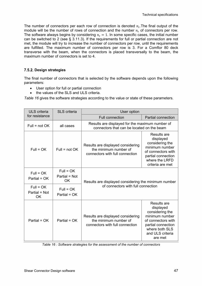
The number of connectors per each row of connection is denoted 𝑛𝑛r.The final output of the module will be the number of rows of connection and the number 𝑛𝑛r of connectors per row. The software always begins by considering 𝑛𝑛r = 1. In some specific cases, the initial number can be switched to 2 (see § 3.11.3). If the requirements for full or partial connection are not met, the module will try to increase the number of connectors per row, until the requirements are fulfilled. The maximum number of connectors per row is 3. For a Comflor 80 deck transverse with the beam, when the connectors is placed transversally to the beam, the maximum number of connectors is set to 4.
Design strategies
The final number of connectors that is selected by the software depends upon the following parameters:
• User option for full or partial connection • the values of the SLS and ULS criteria.
Table 16 gives the software strategies according to the value or state of these parameters.
ULS criteria for resistance
SLS criteria User option Full connection Partial connection
Full = not OK all cases Results are displayed for the maximum number of connectors that can be located on the beam
Full = OK Full = not OK Results are displayed considering
the minimum number of connectors with full connection
Results are displayed
considering the minimum number of connectors with partial connection where the LRFD criteria are met
Full = OK Partial = OK
Full = OK Partial = Not
OK Results are displayed considering the minimum number of connectors with full connection Full = OK
Partial = Not OK
Full = OK Partial = OK
Partial = OK Partial = OK Results are displayed considering
the minimum number of connectors with full connection
Results are displayed
considering the minimum number of connectors with partial connection where both SLS and ULS criteria
are met
Table 16 : Software strategies for the assessment of the number of connectors

48 Shear Connector Design software
Number of connectors for full connection
For a critical cross-section (see § 5.2), the number of connectors is obtained when the resistance of all the connectors between the critical cross section and the closest support is equal to the minimum plastic resistance of the slab and of the profile. The process is detailed hereafter taking into account the type of slab. The location of the i-th critical cross-section is denoted 𝑥𝑥c. a) Slab with decking transverse to the beam axis The number of ribs between the critical cross-section and the closest support is obtained by:
𝑛𝑛ribs =min {𝑥𝑥c ; 𝐿𝐿 − 𝑥𝑥c}
𝑏𝑏𝑠𝑠 (84)
where: 𝑏𝑏𝑠𝑠: see § 3.7 At the first trial, the degree of connection is then calculated by:
𝛽𝛽 =𝑛𝑛ribs�𝑛𝑛𝑟𝑟 𝑃𝑃Rd,t�min �𝑁𝑁a,n;𝑁𝑁c,n�
Where: 𝑁𝑁a,n is the nominal compressive strength of the steel profile, calculated by: 𝑁𝑁a,n = 𝜑𝜑s 𝐴𝐴 𝑓𝑓y
𝑁𝑁c,n is the nominal compressive strength of the concrete slab, calculated by: 𝑁𝑁c,n = 0,85 𝜑𝜑c 𝑓𝑓′c �ℎ − ℎ𝑝𝑝� 𝑏𝑏eff
The number of connectors, denoted 𝑛𝑛f, is then determined according to the value of 𝛽𝛽:
If 𝛽𝛽 < 1, the full connection is not possible. The module will switch to the partial connection option
If 1 ≤ 𝛽𝛽 < 2: 𝑛𝑛f = 𝑛𝑛ribs If 2 ≤ 𝛽𝛽 < 3: 𝑛𝑛f = 𝑛𝑛ribs 2⁄ (A connector is placed at every two ribs) etc…
b) Slab with decking parallel with the beam axis
𝑛𝑛f =min �𝑁𝑁a,n;𝑁𝑁c,n�
𝑛𝑛r 𝑃𝑃Rd,l
c) Solid slab
𝑛𝑛f =min �𝑁𝑁a,n;𝑁𝑁cs,n�
𝑛𝑛r 𝑃𝑃Rd
Where: 𝑁𝑁cs,n = 0,85 𝜑𝜑c 𝑓𝑓′c ℎ 𝑏𝑏eff(𝑥𝑥c) The number of connectors 𝑛𝑛f must fulfil the requirements of connectors positioning as defined in § 3.10 and 3.11. If this control is negative, an error code will be sent back to the interface.
Minimum number of connectors for partial connection
a) Minimum degree of connection The minimum degree of connection, denoted 𝛽𝛽min, is calculated according to AS/NZS 2327 § 3.5.8.3:

Technical specifications
Shear Connector Design software 49
If 𝐿𝐿 ≤ 25 𝑚𝑚: 𝛽𝛽min = 1 − �355 𝑓𝑓y⁄ �(0,75− 0,03𝐿𝐿) ≥ 0,4 (85)
otherwise: 𝛽𝛽min = 1 b) Slab with decking transverse to the beam axis At the first trial, the number of connectors is calculated by assuming the degree of connection equal to ηmin:
𝑛𝑛0 = 𝛽𝛽min 𝑛𝑛f The minimum number of connectors, denoted 𝑛𝑛min, is then determined as follows: If 𝑛𝑛ribs < 𝑛𝑛0, the partial connection is not possible. An error code will be provided. If 𝑛𝑛0 ≤ 𝑛𝑛ribs < 2𝑛𝑛0: 𝑛𝑛min = 𝑛𝑛ribs (A connector is placed at each rib) If 2𝑛𝑛0 ≤ 𝑛𝑛ribs < 3𝑛𝑛0: 𝑛𝑛min = 𝑛𝑛ribs 2⁄ (A connector is placed at every two ribs) etc…
Error code (see Annex E):
If the partial connection is not possible, other calculations will not be performed and an error message will be sent back to the UI (error code = 27).
c) Other slabs The minimum number of connectors is calculated by:
𝑛𝑛min = 𝛽𝛽min 𝑛𝑛f
Determination of the number of connectors for partial connection
Step 1: ULS and SLS verifications with the full connection. If the resistance and deformation criteria are not checked, they will neither be with the partial connection. Otherwise, continue Step 2. Step 2: ULS and SLS verifications with the partial connection. If the resistance and deformation criteria are checked, the number of connectors for partial connection is equal to:
𝑛𝑛 = 𝑛𝑛min Otherwise, continue Step 3. Step 3: Increase the number of connectors until the resistance and deformation criteria are checked.
Degree of shear connection
The degree of shear connection of the composite beams is actually defined by:
𝛽𝛽 =𝑛𝑛rs 𝑃𝑃Rd,t
min �𝑁𝑁a,n;𝑁𝑁c,n� (86)
where 𝑛𝑛rs is the total number of connectors between the critical section and the support.

50 Shear Connector Design software
7.6. ULS verifications principles
Cross-section slenderness
References: AS/NZS 2327 § 3.4.3 and Table 3.4.3.3
For a design in partial connection, a part of steel profile is in compression. The slenderness of the portion of the cross-section in compression is assessed by the software as follows. The location of the plastic neutral axis (PNA) of the composite cross-section is calculated first (see Annex C). The portion of the cross-section in compression is then assessed. If the PNA is located in or below the upper flange, the latter is assumed in uniform compression. Its slenderness 𝜆𝜆ef is obtained by Formula (57). The section plasticity and yield slenderness limits (𝜆𝜆efp and 𝜆𝜆efy respectively) of the flange in uniform compression are given in Table 17 (from Table 3.4.3.3 of AS/NZS 2327 [7]).
Type of profile Plasticity limit 𝜆𝜆efp Yield limit 𝜆𝜆efy
Profiles from the database (hot-rolled) 9 16
Custom profiles (built-up heavily welded) 8 14
Table 17: Slenderness limits for flanges acc. to Australasian standard
The upper flange is classified as follows: compact if: 𝜆𝜆ef ≤ 𝜆𝜆efp non-compact if: 𝜆𝜆efp < 𝜆𝜆ef ≤ 𝜆𝜆efy slender if: 𝜆𝜆ef > 𝜆𝜆efy
According to the notes of Table 3.4.3.3 in AS/NZ 2327, the web is classified without consideration of the presence of the slab. The web slenderness 𝜆𝜆ew is obtained by Formula (58). The section plasticity and yield slenderness limits (𝜆𝜆ewp and 𝜆𝜆ewy respectively) of the web are calculated as follows (from Table 3.4.3.3 of AS/NZS 2327 [7]).
𝜆𝜆ewp =
1114,7 𝑟𝑟p − 1
for 0,5 ≤ 𝑟𝑟p ≤ 1,0
𝜆𝜆ewp =41𝑟𝑟p
for 𝑟𝑟p < 0,5 (87)
𝜆𝜆ewy =60𝑟𝑟e
for 0 ≤ 𝑟𝑟e ≤ 1,0 (88)
In Formula (87), 𝑟𝑟p is the ratio of the distance from the PNA to the compression edge of the web to the depth of the web. In Formula (88), 𝑟𝑟e is the ratio of the distance from the elastic neutral axis (ENA) to the compression edge of the web to the depth of the web. Both rp and re are assessed considering the composite gross cross-section. In partly in compression, the web is classified as follows: compact if: 𝜆𝜆ew ≤ 𝜆𝜆ewp non-compact if: 𝜆𝜆ewp < 𝜆𝜆ew ≤ 𝜆𝜆ewy slender if: 𝜆𝜆ew > 𝜆𝜆ewy
AS/NZS 2327 does not allow to have slender elements. So that if either the upper flange or the web is slender, an error code is sent back to the interface and the calculations are stopped.

Technical specifications
Shear Connector Design software 51
Non-compact cross-sections are not allowed for partial connection as mentioned in AS/NZS 2327 §3.6.1.1.
Error code (see Annex D): For partial connection, if a cross-section is classified as non-compact, other calculations are not performed and an error message is displayed in the UI (error code = 33).
ULS plastic design and effective portion of the steel beam
References: AS/NZS 2327 § 3.4.3 and Table 3.4.3.3
According to AS/NZS standards, a plastic design of the beams is always carried out, considering an effective cross-section. The effective portion of the steel beam is assessed as follows: all elements of the section in tension are fully effective; all compact elements (upper flange and web) in compression are fully effective; if the upper flange (in compression) is classified as non-compact, its effective width is
obtained as follows:
𝑏𝑏f,eff = 𝑡𝑡w + 2 𝜆𝜆efp𝑡𝑡f (89)
if a part of the web is in compression and is classified as non-compact, its effective portion is obtained by removing the ineffective part at the centre of the portion in compression (see Figure 26). Both remaining effective parts have a width of 15 𝑡𝑡w 𝜀𝜀, where 𝜀𝜀 is defined by:
𝜀𝜀 = �250𝑓𝑓y
(90)
PNA = plastic neutral axis of the gross composite steel cross-section
Figure 26 : Effective portion of a non-compact steel section for plastic design of composite beams
52 Shear Connector Design software
7.7. Strength verifications
Section bending moment capacity
References: AS/NZS 2327 § 3.5.2 and 3.5.4
The criterion for the verification of section to the bending moment about the principal axis is: ΓMc = 𝑀𝑀∗ 𝑀𝑀R⁄ ≤ 1.0 (91)
where 𝑀𝑀∗ is the design bending moment; 𝑀𝑀R is the design moment capacity, obtained according to Annex C
Shear capacity
References: AS/NZS 2327 § 3.5.5
The same criterion as in § 6.2.5 is applied, using the capacity factor 𝜙𝜙v of Table 14. The contribution of the slab is ignored. The resistance to shear buckling is also applied to composite sections. For a partial connection (𝛽𝛽 < 1), the nominal shear capacity is calculated by:
𝑉𝑉V,β = 𝛼𝛼𝑉𝑉V (92)
Where: 𝛼𝛼 = (1 − 𝛽𝛽) (0.76 λsd + 0.92)⁄ + 𝛽𝛽 λsd = ℎsl �ℎsl + ℎp�⁄
Interaction of shear and bending moment
References: AS/NZS 2327 § 3.5.6
The shear and bending interaction is verified through the following criterion:
Γvmc = �𝑀𝑀∗
𝑀𝑀R�3
+ �𝑉𝑉∗
𝑉𝑉R�6
≤ 1.0 (93)
where 𝑉𝑉∗ is the design shear force; 𝑀𝑀∗ is the design bending moment; 𝑀𝑀R is the design moment capacity of the section, see § 7.7.1; 𝑉𝑉R is the shear capacity of the section, given by 𝑉𝑉R = 𝜙𝜙v 𝑉𝑉v of the section; 𝑉𝑉v is the design shear capacity of the section, see § 6.2.5; 𝜙𝜙v is the capacity factor (strength reduction factor) for shear resistance – see Table 14;
Technical specifications
Shear Connector Design software 53
7.8. SLS verifications
General
For unpropped beams, the deflection under the dead loads (in permanent load case) is obtained considering the steel part only (without composite effect). If the user has defined additional loads in the permanent load lase, their effect on deflection is calculated considering the composite effect with the long term modular ratio. For fully propped beams, the deflection under permanent load case is obtained considering the composite effect with the long term modular ratio. For the composite stage live loads, the deflections are calculated considering the composite effect with the short term modular ratio. The vibrations check needs to calculate the fundamental natural frequency of the composite beam. The later is evaluated by using the Rayleigh method in which all deflections are calculated considering the composite effect with the short term modular ratio. According to AS/NZS 2327 § 3.10.3.2 and § 3.10.3.3, the modular ratio used for the calculations of composite stage deflections are defined as follows:
short term actions : 𝑛𝑛eq =𝐸𝐸s
𝐸𝐸c (94)
long term actions (*) : 𝑛𝑛eq = 3𝐸𝐸s
𝐸𝐸c (95)
(*): modular ratio for long term actions includes the effect of creep; where: 𝐸𝐸s,𝐸𝐸c : see § 3.5.2 and § 3.6.2 respectively.
Formula (94) is a simplified approach based on engineering judgement. It is also adopted for Eurocodes and North American standards.
Deflection limits
According to AS/NZS 2327, the deflection of the beam should be checked for: total deflection, under short term and long term loading effects; incremental deflection, which occurs after a chosen stage in the life of the structure.
See § 4.2 for the definition of SLS combination of loads for the calculation of deflections. AS/NZS 2327 provides informative deflection limits in Annex B of the Standards. The total deflection is always checked with a common limit of 1/250 of the span length. According to the type of finishes, a check of the incremental deflection is also recommended, with a typical limit of 1/500 of the span length. In the software: the total check is always checked, with a default limit of L/250; the check of the incremental deflection is optional, with a default limit of L/500.
Vibrations
References: AS/NZS 2327 § 6.4.2.2

54 Shear Connector Design software
The floor vibration check is carried out according to AS/NZS 2327 [7] § 6.4.2 and [6]. At first, the fundamental natural frequency (𝑓𝑓𝑢𝑢) is calculated using the Rayleigh method. Then, specific criterion is applied for two types of excitation (when relevant, according to the options selected by the User): Walking activities; Synchronised crowd movement.
Vibrations checks for walking activities
The checking method applied by the software depends on the value of the fundamental natural frequency: Low frequency floors: 𝑓𝑓𝑢𝑢 ≤ 10 Hz High frequency floors: 𝑓𝑓𝑢𝑢 > 10 Hz
Low frequency floors The total weighted root-mean-squared (rms) acceleration is calculated assuming a resonant response to one of the harmonics of walking frequency as follows:
𝑎𝑎𝑤𝑤,𝑟𝑟𝑐𝑐𝑠𝑠 = 𝜇𝜇𝑑𝑑 𝜇𝜇𝑟𝑟0,1𝑄𝑄
2√2𝑀𝑀 ξ𝑊𝑊𝜌𝜌 ≤ 𝑎𝑎0 (96)
Where: 𝜇𝜇𝑑𝑑 mode shape factor at the point of excitation; 𝜇𝜇𝑑𝑑 = 1,0 𝜇𝜇𝑟𝑟 mode shape factor at the point of response; 𝜇𝜇𝑟𝑟 = 1,0 ξ critical damping ratio 𝑄𝑄 weight of a person; 𝑄𝑄 = 746 𝑁𝑁 (76 kg x 9,81 m/s2) 𝑊𝑊 frequency weighting factor, given in §7.6 of [6] or in Figure 27
Figure 27 : Frequency weighting factor (Figure 7.5 of [6])
𝑀𝑀 modal mass, calculated by: 𝑀𝑀 = 𝑚𝑚𝐿𝐿eff𝑆𝑆
𝑚𝑚 floor mass per unit area including dead load and variable load (expressed in kg/m2), calculated by: 𝑚𝑚 = (𝐺𝐺 + 0,2𝑄𝑄) 𝑘𝑘⁄
𝐿𝐿eff effective floor length, calculated by:
𝐿𝐿eff = 1,09(1,10)𝑢𝑢𝑦𝑦−1 �𝐸𝐸𝐼𝐼b𝑚𝑚𝑏𝑏𝑓𝑓𝑢𝑢2
�1 4⁄
≤ 𝑛𝑛𝑦𝑦𝐿𝐿
𝑛𝑛y number of bays in the direction of the beam; 𝑛𝑛y = 1

Technical specifications
Shear Connector Design software 55
𝐸𝐸𝐼𝐼b dynamic flexural rigidity of the composite beam (expressed in N.m2) 𝐿𝐿 length of the beam 𝑏𝑏 beam spacing, taken as: 𝑏𝑏 = max{𝑏𝑏L ; 𝑏𝑏R} 𝑓𝑓𝑢𝑢 fundamental frequency 𝑆𝑆 effective floor width, calculated by:
𝑆𝑆 = η(1,15)𝑢𝑢𝑥𝑥−1 �𝐸𝐸𝐼𝐼𝑠𝑠𝑚𝑚𝑓𝑓𝑢𝑢2
�1 4⁄
≤ 𝑛𝑛𝑥𝑥𝐿𝐿𝑥𝑥
𝐿𝐿x span of the primary beam (beam in the other direction), taken as: 𝐿𝐿x = 𝑏𝑏L + 𝑏𝑏R 𝑛𝑛x number of bays in the direction of the primary beam; 𝑛𝑛x = 1 η factor that accounts for the influence of floor frequency of the response of the
slab, calculated by: η = 0,5 when 𝑓𝑓𝑢𝑢 < 5𝐻𝐻𝐻𝐻 η = 0,21𝑓𝑓𝑢𝑢 − 0,55 when 5 𝐻𝐻𝐻𝐻 ≤ 𝑓𝑓𝑢𝑢 ≤ 6 𝐻𝐻𝐻𝐻 η = 0,71 when 𝑓𝑓𝑢𝑢 > 6𝐻𝐻𝐻𝐻
𝐸𝐸𝐼𝐼s dynamic flexural rigidity of the slab (expressed in N.m2) 𝑎𝑎0 the acceleration limit; given in Table 18, according to in ISO 2631:
Activity Acceleration limit
𝑎𝑎0 𝑘𝑘⁄ (%)
1 Hz 4-8Hz 40 Hz
Offices, Residences 1.0 0.5 2.5
Shopping Malls, Dining and Dancing 3.0 1.5 7.0
Rythmic activities 10.0 5.0 25.0
For frequency ranges 1-4 Hz and 8-40 Hz, acceleration limits is obtained by linear interpolation
Table 18 : Recommended peak acceleration for human comfort for vibrations due to human activities.
High frequency floors If the fundamental frequency is greater than 10 Hz, the rms acceleration should be calculated by:
𝑎𝑎𝑤𝑤,𝑟𝑟𝑐𝑐𝑠𝑠 = 2𝜋𝜋𝜇𝜇𝑑𝑑 𝜇𝜇𝑟𝑟186𝑀𝑀𝑓𝑓𝑢𝑢
0,3𝑄𝑄
7001√2
𝑊𝑊 ≤ 𝑎𝑎0 (97)

56 Shear Connector Design software
Vibration check for synchronised crowd movement
When floors are subject to dancing and jumping activities characterized by synchronized crowd movement (as defined in option by the User), the simplified approach of § 6.4.3.1.2 of AS/NZ 2327 is considered in the calculation module (“design to avoid resonance”). The check criterion is:
𝑓𝑓1 > 8,4 𝐻𝐻𝐻𝐻 (98)
The far more complex approach “to withstand the anticipated dynamic loads” of the standard is not considered in the module.
Calculation of the fundamental natural frequency
The fundamental natural frequency of the composite beam, expressed in Hz, is assessed by the Rayleigh method, expressed by the following general formula:
𝑓𝑓 =1
2 𝜋𝜋 �𝑘𝑘
∑𝑃𝑃𝑐𝑐 |𝑤𝑤𝑐𝑐|∑𝑃𝑃𝑐𝑐 𝑤𝑤𝑐𝑐2
(99)
where: 𝑃𝑃𝑐𝑐 is the applied load at design point no i 𝑤𝑤𝑐𝑐 is the deflection of the beam at design point no I under the applied loads Pi. 𝑘𝑘 = 9,81 m/s2
The dynamic modulus of elasticity of concrete is taken as: 𝐸𝐸c,dyn = 1,1 𝐸𝐸c

Technical specifications
Shear Connector Design software 57
7.9. Longitudinal shear resistance
Introduction
The calculation module will assess the transverse reinforcement required to carry the longitudinal from the concrete to the connectors. Following assumptions will be considered: For beams, with plain slabs, two layers of reinforcement are assumed. The connectors
go through the bottom layer but not trough the top one. Calculations are performed for 2 shear areas (a-a and b-b). See Figure 28 a).
For slabs with profiled steel sheeting, either longitudinal or perpendicular, only one layer is assumed (Figure 28 b) to d). Calculations are performed for one shear area (a-a).
For perpendicular profiled sheeting, the contribution of the sheeting to the longitudinal shear resistance is taken into account when the sheeting is continuous over the beam flange (See Figure 28 c).
a) plain slab b) slab with longitudinal profiled sheeting
c) slab with continuous
perpendicular profiled sheeting d) slab with not-continuous
perpendicular profiled sheeting
Figure 28: Transverse reinforcement configurations and shear areas
Minimum transverse reinforcement ratio
References: AS/NZS 2327 § 3.8.6
The minimum area of transverse reinforcement required by AS/NZS 2327 (see § 3.8.6 of the standard) is given by:
𝜌𝜌min = 0,08�𝑓𝑓c
′
𝑓𝑓sy (100)
where : 𝑓𝑓c′ see § 3.6.2 𝑓𝑓sy see § 3.8
The cross-sectional area of transverse reinforcement per unit length of beam should also fulfil the following condition:

58 Shear Connector Design software
𝐴𝐴ts ≥ 0,8𝑑𝑑s 𝜎𝜎1𝑓𝑓sy
(101)
where : 𝑑𝑑s see definition after Formula (105) 𝜎𝜎1 = 1 MPa
When two layers of transverse reinforcement are used, the lower layer should represent at least 50% (𝐴𝐴b ≥ 0,5 𝐴𝐴ts).
Design of transverse reinforcement
References: AS/NZS 2327 § 3.8.4
Figure 29 : Transverse reinforcement
The calculation is carried out for a segment between each critical section (see § 5.2) and the closest support. For plain slabs, it is performed for the 2 shear areas, where the most unfavourable results are kept. Following steps are applied: Calculation of the longitudinal shear to be transferred by the reinforcement through the shear area
The longitudinal shear Δ𝐹𝐹d between the critical section and the closest support that should be transferred by the reinforcement through the shear area is given by:
Shear area a-a: Δ𝐹𝐹d =𝑁𝑁c,d
𝑏𝑏eff(𝑥𝑥c) max�𝑏𝑏eff,left(𝑥𝑥c); 𝑏𝑏eff,right(𝑥𝑥c)� (102)
Shear area b-b: Δ𝐹𝐹d = 𝑁𝑁c,d (103)

Technical specifications
Shear Connector Design software 59
where: 𝑥𝑥c is the location of the critical section; 𝑁𝑁c,d resulting compression force in the concrete slab at the critical section, given by:
𝑁𝑁c,d = 0,85 𝜙𝜙c 𝑓𝑓c′ 𝑒𝑒part(𝑥𝑥c) 𝑏𝑏eff(𝑥𝑥c) (104)
𝑏𝑏eff(𝑥𝑥c) is the effective width of concrete slab at the critical section (see § 7.1); 𝑏𝑏eff,left(𝑥𝑥c) and 𝑏𝑏eff,right(𝑥𝑥c) are the part of this effective width on the LHS and RHS respectively, with:
𝑏𝑏eff(𝑥𝑥c) = 𝑏𝑏eff,left(𝑥𝑥c) + 𝑏𝑏eff,right(𝑥𝑥c) 𝑒𝑒part(𝑥𝑥c) see § 7.4 𝜙𝜙c see Table 14 𝑓𝑓c′ see § 3.6.2
Calculation of the longitudinal shear force per unit length through the shear area
The design longitudinal shear force per unit length of the beam on the particular shear plane is determined by (see § 3.8.2 of AS/NZS 2327):
𝜈𝜈Lp∗ =
Δ𝐹𝐹d
𝑛𝑛sp 𝑠𝑠 (105)
where: 𝑛𝑛sp is the number of shear plane through which the shear force is transferred; 𝑛𝑛sp = 2 for the shear area b-b of an intermediate beam with plain slab, and 𝑛𝑛sp = 1 for any other case; 𝑠𝑠 is the shear length, which is obtained as follows: for a critical section associated to a concentrated load, the shear length is
the distance to the closest support, for a critical section associated to the maximum bending of the ULS
combination, the shear length is the shortest distance between a support and the cross-section where the compression force in the slab is obtained. For partial connection, this distance is equal to the distance to the closest support. But in full connection, the shear length is lower than the distance to the relevant support (see Figure 30).
Check of the concrete strut under compression and calculation of the orientation of the strut
According to § 3.8.3 of AS/NZS 2327, the resistance of the concrete compression strut is checked by the following formula:
𝜈𝜈Lp∗
𝑑𝑑s≤ 𝜙𝜙c 𝑓𝑓c
′ 𝜈𝜈 sin𝜃𝜃f cos𝜃𝜃f (106)
where: 𝑑𝑑s is the height of the concrete slab (𝑑𝑑s = ℎsl for plain slabs and 𝑑𝑑s = ℎsl − ℎp for slabs with profiled steel sheeting).
𝜙𝜙c see Table 14 𝑓𝑓c′ see § 3.6.2
ν is a strength reduction factor given by:
𝜈𝜈 = 0,6 �1 −𝑓𝑓c′
250� (107)

60 Shear Connector Design software
𝜃𝜃f is the orientation of the concrete strut under compression, which is calculated by the following equation:
𝜃𝜃f =12
arcsin�2 𝜈𝜈Lp
∗
𝜈𝜈 𝑑𝑑s 𝜙𝜙c 𝑓𝑓c′� but 1 ≤ cotg𝜃𝜃f ≤ 2 (108)
Formula (105) is coming from Equation 3.8.4 (2) of AS/NZS 2327. The latter is obviously false and following corrections have been made: introduction of 𝜈𝜈 factor which is missing in AS/NZS 2327; unit consistent formula: the left part is divided by 𝑑𝑑s and not the right
one.
The criterion for the resistance of the concrete strut under compression is finally assessed, with the last orientation obtained with the previous process:
Γc,strut = 𝜈𝜈Lp∗ /𝑑𝑑s
𝜙𝜙c 𝑓𝑓c′ 𝜈𝜈 sin𝜃𝜃f cos𝜃𝜃f
≤ 1 (109)
in the figure: Δ𝑥𝑥 = 𝑠𝑠
Figure 30 : Shear length

Technical specifications
Shear Connector Design software 61
Assessment of the transverse reinforcement For each shear area, the transverse reinforcement required is obtained by:
𝐴𝐴ts ≥𝜈𝜈Lp∗
𝜙𝜙sr 𝑓𝑓sy cot𝜃𝜃f (110)
where: 𝑓𝑓sy see § 3.8 𝜙𝜙sr see Table 14 𝜃𝜃f is the orientation of the strut obtained at the previous step for the resistance of concrete; 𝐴𝐴ts is the cross-sectional area of transverse reinforcement per unit length of beam
For slabs with profiled steel sheeting, with only one layer of transverse reinforcement, this previous equation directly gives the transverse reinforcement required for the slab. For plain slabs, the calculation performed for the shear area b-b gives directly the design of the bottom layer of reinforcement 𝐴𝐴b. The calculation performed for the shear area a-a gives 𝐴𝐴ts = 𝐴𝐴t + 𝐴𝐴b.
Influence of continuous perpendicular profiled steel sheeting For slabs with continuous perpendicular profiled steel sheeting, the previous equation (109) is replaced by:
𝐴𝐴ts ≥ max�0;𝜈𝜈Lp∗
𝜙𝜙sr 𝑓𝑓sy cot𝜃𝜃f− 𝐴𝐴pe
𝜙𝜙s 𝑓𝑓yp
𝜙𝜙sr 𝑓𝑓sy� (111)
where: fyp see § 3.7 𝐴𝐴pe is the area of the profiled sheeting per length unit, calculated by:
𝐴𝐴pe =𝑡𝑡p
𝑏𝑏s�𝑏𝑏s + 𝑏𝑏b − 𝑏𝑏t + �(𝑏𝑏b − 𝑏𝑏t)2 + 4 ℎ𝑝𝑝2� (112)
𝑡𝑡p, ℎp, 𝑏𝑏s, 𝑏𝑏b, 𝑏𝑏t: see § 3.7
Formula (110) is not provided directly by AS/NZS but is an adaptation of the equation proposed by EN 1994-1-1 and already used in the X-HVB software in Eurocode version. For continuous perpendicular profiled steel sheetings, AS/NZS proposes an equation 2.7.2. (5) which comprises the same terms than in Eurocode but is also limited by a term that depends on the parameters of studs welded through the deck, which is obviously not applicable for XHVB.
Control of the minimum reinforcement criterion
At the end of the process, it is checked that the transverse reinforcement obtained by calculation are greater than the minimal requirement according to § 7.9.2, i.e.
plain slabs: 𝐴𝐴b ≥12𝜌𝜌min 𝑑𝑑s ; 𝐴𝐴t ≥
12𝜌𝜌min 𝑑𝑑s ; 𝐴𝐴b ≥ 0,5 𝐴𝐴ts (113)
composite slabs: 𝐴𝐴ts ≥ 𝜌𝜌min 𝑑𝑑s (114)

62 Shear Connector Design software
: PROPERTIES OF THE STEEL SECTION The following section properties are calculated using analytical formulae:
𝐴𝐴 Section area 𝐴𝐴 = 2𝑏𝑏𝑠𝑠𝑡𝑡𝑠𝑠 + �ℎ − 2𝑡𝑡𝑠𝑠�𝑡𝑡𝑤𝑤 + (4 − 𝜋𝜋)𝑟𝑟𝑐𝑐2
𝐼𝐼x Second moment of area about the strong axis
𝐼𝐼x =1
12 �𝑏𝑏𝑠𝑠ℎ3 + �𝑏𝑏𝑠𝑠 − 𝑡𝑡𝑤𝑤��ℎ − 2𝑡𝑡𝑠𝑠�
3� + 4𝑘𝑘𝑟𝑟𝑐𝑐4 + (4 − 𝜋𝜋)𝑟𝑟𝑐𝑐2 �ℎ2− 𝑡𝑡𝑠𝑠 − 𝑟𝑟𝑐𝑐 +
2𝑟𝑟𝑐𝑐3(4 − 𝜋𝜋)�
2
with:
𝑘𝑘 =13−𝜋𝜋
16−
19(4 − 𝜋𝜋)
𝐼𝐼y Second moment of area about the weak axis
𝐼𝐼y =1
12 �2𝑡𝑡𝑠𝑠𝑏𝑏𝑠𝑠3 + �ℎ − 2𝑡𝑡𝑠𝑠�𝑡𝑡𝑤𝑤3 �+ 4𝑘𝑘𝑟𝑟𝑐𝑐4 + (4 − 𝜋𝜋)𝑟𝑟𝑐𝑐2 �
𝑡𝑡𝑤𝑤2
+ 𝑟𝑟𝑐𝑐 −2𝑟𝑟𝑐𝑐
3(4 − 𝜋𝜋)�2
𝑊𝑊pl,x Plastic modulus for bending about the strong axis
𝑊𝑊pl,x =𝑡𝑡𝑤𝑤ℎ2
4+ 𝑡𝑡𝑠𝑠�𝑏𝑏𝑠𝑠 − 𝑡𝑡𝑤𝑤��ℎ − 𝑡𝑡𝑠𝑠� + (4 − 𝜋𝜋)𝑟𝑟𝑐𝑐2 �
ℎ2− 𝑡𝑡𝑠𝑠� +
(3𝜋𝜋 − 10)𝑟𝑟𝑐𝑐3
3
𝑊𝑊pl,y Plastic modulus for bending about the weak axis
𝑊𝑊pl,y =𝑡𝑡𝑠𝑠𝑏𝑏𝑠𝑠2
2+𝑡𝑡𝑤𝑤2
4 �ℎ − 2𝑡𝑡𝑠𝑠� + (4 − 𝜋𝜋)𝑟𝑟𝑐𝑐2 �𝑡𝑡𝑤𝑤2
+ 𝑡𝑡𝑠𝑠� −2𝑟𝑟𝑐𝑐3
3
𝑊𝑊el,x Elastic modulus for bending about the strong axis
𝑊𝑊el,x =2𝐼𝐼𝑦𝑦ℎ
𝑊𝑊el,y Elastic modulus for bending about the weak axis
𝑊𝑊el,y =2𝐼𝐼𝑧𝑧𝑏𝑏𝑠𝑠
𝐴𝐴v,x Shear area for a shear force perpendicular to the web 𝐴𝐴v,x = 2𝑏𝑏𝑠𝑠 𝑡𝑡𝑠𝑠
𝐴𝐴v,y Shear area for a shear force parallel to the web 𝐴𝐴v,x = 𝐴𝐴 − 2𝑏𝑏𝑠𝑠𝑡𝑡𝑠𝑠 + 𝑡𝑡𝑠𝑠(𝑡𝑡𝑤𝑤 + 2𝑟𝑟𝑐𝑐)
𝐽𝐽 Torsional constant 𝐽𝐽
=23𝑏𝑏𝑠𝑠𝑡𝑡𝑠𝑠3 �1 − 0,63
𝑡𝑡𝑠𝑠𝑏𝑏𝑠𝑠�1 −
𝑡𝑡𝑠𝑠4
12𝑏𝑏𝑠𝑠4��+
13𝑡𝑡𝑤𝑤3 �ℎ − 2𝑡𝑡𝑠𝑠�
+ 2𝑡𝑡𝑤𝑤𝑡𝑡𝑠𝑠�0,1
𝑟𝑟𝑐𝑐𝑡𝑡𝑠𝑠
+ 0,15� ��𝑡𝑡𝑠𝑠 + 𝑟𝑟𝑐𝑐�
2 + 𝑡𝑡𝑤𝑤(𝑟𝑟𝑐𝑐 + 𝑡𝑡𝑤𝑤 4⁄ )𝑡𝑡𝑠𝑠 + 2𝑟𝑟𝑐𝑐
�
4
𝐼𝐼𝑤𝑤 Warping constant
𝐼𝐼𝑤𝑤 = 0,25 𝐼𝐼𝑧𝑧 �ℎ − 𝑡𝑡𝑠𝑠�2
Technical specifications
Shear Connector Design software 63
: ELASTIC PROPERTIES OF A COMPOSITE BEAM Considering a load case under composite stage, with a modular ratio equal to neq,j, the location of the elastic neutral axis (𝑦𝑦ENA,j, measured from the lower fiber of the bottom flange) and the second moment of area of the composite cross-section about the major axis (𝐼𝐼x,j) are obtained as follows. Composite section with steel profiled sheeting, ENA located in the steel profile:
Location of the elastic neutral axis:
𝑦𝑦ENA,j =𝐴𝐴ℎ𝑡𝑡 2⁄ + 𝑏𝑏eff�ℎ − ℎ𝑝𝑝��ℎ𝑡𝑡 + �ℎ + ℎp� 2⁄ � 𝑛𝑛eq,j�
𝐴𝐴 + 𝑏𝑏eff�ℎ − ℎ𝑝𝑝� 𝑛𝑛eq,j�
Criterion to check the assumption: 𝑦𝑦ENA,j ≤ ℎt + ℎp Second moment of area:
𝐼𝐼x,j
= 𝐼𝐼x,a + 𝐴𝐴�ℎ𝑡𝑡 2⁄ − 𝑦𝑦ENA,j�2 +
𝑏𝑏eff�ℎ − ℎ𝑝𝑝�3
12 𝑛𝑛eq,j
+𝑏𝑏eff�ℎ − ℎ𝑝𝑝�
𝑛𝑛eq,j�ℎ𝑡𝑡 + �ℎ + ℎp� 2⁄ − 𝑦𝑦ENA,j�
2
Where: 𝐼𝐼x,a and A are the second moment of area and the section area of the steel profile, given in Annex A;
j is the index for the type of actions: j = l for long-term actions; j = s for short-term actions;
𝑛𝑛eq,j is the modular ratio, for short-term or long-terms actions. Composite section with steel profiled sheeting, ENA located in the concrete slab:
Location of the elastic neutral axis:
𝑦𝑦ENA,j = 𝑑𝑑n,j − �𝑑𝑑n,j2 −
𝑛𝑛eq,j𝐴𝐴𝑏𝑏eff
ℎt − (ℎ + ℎt)2
Where: 𝑑𝑑n,j = 𝑛𝑛eq,j 𝐴𝐴 𝑏𝑏eff⁄ + (ℎ + ℎt) Criterion to check the assumption: 𝑦𝑦ENA,j > ℎt + ℎp Second moment of area: 𝐼𝐼x,j
= 𝐼𝐼x,a + 𝐴𝐴 �ℎt2− 𝑦𝑦ENA,j�
2
+𝑏𝑏eff�ℎ + ℎt − 𝑦𝑦ENA,j�
3
12 𝑛𝑛eq,j
+𝑏𝑏eff�ℎ + ℎt − 𝑦𝑦ENA,j�
4 𝑛𝑛eq,j�ℎ + ℎt − 𝑦𝑦ENA,j�
2

64 Shear Connector Design software
Composite section with a plain slab, ENA located in the steel profile: Location of the elastic neutral axis:
𝑦𝑦ENA,j =𝐴𝐴ℎ𝑡𝑡 2⁄ + 𝑏𝑏effℎ(ℎt + ℎh + ℎ 2⁄ ) 𝑛𝑛eq,j⁄ + 𝑏𝑏fℎh(ℎt + ℎh 2⁄ ) 𝑛𝑛eq,j⁄
𝐴𝐴 + 𝑏𝑏effℎ 𝑛𝑛eq,j⁄ + 𝑏𝑏fℎh 𝑛𝑛eq,j⁄
Criterion to check the assumption: 𝑦𝑦ENA,j ≤ ℎt Second moment of area:
𝐼𝐼x,j
= 𝐼𝐼x,a + 𝐴𝐴 �ℎt2− 𝑦𝑦ENA,j�
2
+𝑏𝑏effℎ3
12𝑛𝑛eq,j+𝑏𝑏effℎ𝑛𝑛eq,j
�ℎ𝑡𝑡 + ℎh +ℎ2− 𝑦𝑦ENA,j�
2
+𝑏𝑏fℎh3
12𝑛𝑛eq,j
+𝑏𝑏fℎh𝑛𝑛eq,j
�ℎ𝑡𝑡 + ℎh 2⁄ − 𝑦𝑦ENA,j�2
Composite section with a plain slab, ENA located in the concrete haunch, if any:
Location of the elastic neutral axis:
𝑦𝑦ENA,j = 𝑑𝑑n,j − �𝑑𝑑n,j2 −
𝑛𝑛eq,j 𝐴𝐴𝑏𝑏f
ℎt −𝑏𝑏eff ℎ𝑏𝑏f
(2ℎh + 2ℎt + ℎ) − (ℎh + ℎt)2
Where: 𝑑𝑑n,j = 𝑛𝑛eq,j𝐴𝐴 𝑏𝑏eff⁄ + 𝑏𝑏effℎ 𝑏𝑏f⁄ + (ℎh + ℎt) Criterion to check the assumption: 𝑦𝑦ENA,j ≤ ℎt + ℎh Second moment of area:
𝐼𝐼x,j
= 𝐼𝐼x,a + 𝐴𝐴 �ℎt2− 𝑦𝑦ENA,j�
2
+𝑏𝑏eff ℎ3
12 𝑛𝑛eq,j+𝑏𝑏eff ℎ𝑛𝑛eq,j
�ℎ𝑡𝑡 + ℎh +ℎ2− 𝑦𝑦ENA,j�
2
+𝑏𝑏f�ℎh + ℎt − 𝑦𝑦ENA,j�
3
12 𝑛𝑛eq,j+𝑏𝑏f �ℎh + ℎt − 𝑦𝑦ENA,j�
4 𝑛𝑛eq,j�ℎh + ℎt − 𝑦𝑦ENA,j�
2
Composite section with a plain slab, ENA located in the concrete slab:
Location of the elastic neutral axis:
𝑦𝑦ENA,j = 𝑑𝑑n,j − �𝑑𝑑n,j2 −
𝑛𝑛eq,j𝐴𝐴𝑏𝑏eff
ℎt − (ℎh + ℎt + ℎ)2 > ℎt + ℎh
Where: 𝑑𝑑n,j = 𝑛𝑛eq,j𝐴𝐴 𝑏𝑏eff⁄ + (ℎh + ℎt + ℎ) Criterion to check the assumption: 𝑦𝑦ENA,j > ℎt + ℎh Second moment of area:
𝐼𝐼x,j
= 𝐼𝐼x,a + 𝐴𝐴 �ℎt2− 𝑦𝑦ENA,j�
2
+𝑏𝑏eff �ℎh + ℎt + ℎ − 𝑦𝑦ENA,j�
3
12 𝑛𝑛eq,j
+𝑏𝑏eff �ℎh + ℎt + ℎ − 𝑦𝑦ENA,j�
4 𝑛𝑛eq,j�ℎh + ℎt + ℎ − 𝑦𝑦ENA,j�
2

Technical specifications
Shear Connector Design software 65
: PLASTIC FLEXURAL STRENGTH OF THE COMPOSITE CROSS-SECTION The plastic flexural strength of a cross section is assessed considering the participating depth of the slab (see § 7.4). Capacity factors Following capacity factors are used for the calculation of the plastic moment capacity of the composite cross-section:
𝜙𝜙s capacity factor for steel under axial force – see Table 14 𝜙𝜙c capacity factor for concrete in compression – see Table 14
Plastic Neutral Axis in the concrete slab
Figure 31: Plastic stresses at limit state of yielding
The position of the plastic neutral axis (PNA) in the concrete slab is calculated by (see Figure 31):
𝑦𝑦PNA,c =𝑁𝑁y,d
0,85 𝜙𝜙c 𝑓𝑓c′ 𝑏𝑏eff(𝑥𝑥) ≤ ℎ − ℎp
where: 𝑏𝑏eff(𝑥𝑥) is the effective width of the concrete slab at the abscissa x ℎp = 0 for solid slabs 𝑁𝑁y,d is the design axial force resisted by the steel section at yield:
𝑁𝑁y,d = 𝐴𝐴 𝜙𝜙s 𝑓𝑓y The moment capacity of the composite section is calculated by:
𝑀𝑀R = 𝑁𝑁c,d �ℎ +ℎt − 𝑦𝑦PNA,c
2�
Where: 𝑁𝑁c,d is the resulting compression force in the concrete slab, determined by: 𝑁𝑁c,d = 0,85 𝜙𝜙c 𝑓𝑓′c 𝑦𝑦PNA,c 𝑏𝑏eff(𝑥𝑥)

66 Shear Connector Design software
Plastic Neutral Axis in the steel section 1) If 𝑁𝑁y,d ≥ 𝑁𝑁c,d ≥ 𝑁𝑁y,f, PNA is located in the top flange:
𝑦𝑦PNA,a = ℎt −𝑁𝑁y,d − 𝑁𝑁c,d
2 𝑏𝑏 𝜙𝜙s 𝑓𝑓y
Where: 𝑁𝑁y,f = (𝐴𝐴 − 2 𝑏𝑏 𝑡𝑡f) 𝑓𝑓y The plastic moment capacity of the section is calculated by:
𝑀𝑀R = �ℎt − 𝑦𝑦PNA,a� 𝑏𝑏 𝑦𝑦PNA,a 𝜙𝜙s 𝑓𝑓y + 𝑀𝑀c
2) If 𝑁𝑁y,w ≥ 𝑁𝑁c,d, PNA is located in the web:
𝑦𝑦PNA,a =ℎt2
+𝑁𝑁c,d
2 𝑡𝑡w 𝜙𝜙s 𝑓𝑓y
Where: 𝑁𝑁y,w = (ℎt − 2𝑡𝑡f − 2𝑟𝑟1) 𝑡𝑡w 𝜙𝜙s 𝑓𝑓y The moment capacity of the composite section of the section is calculated by:
𝑀𝑀R = �𝑊𝑊pl,x −14𝑡𝑡w �
𝑁𝑁c,d
𝑡𝑡w 𝜙𝜙s 𝑓𝑓y�2
�𝜙𝜙s 𝑓𝑓y +𝑀𝑀c
3) If 𝑁𝑁y,f > 𝑁𝑁c,d > 𝑁𝑁y,w, PNA is located in the fillets. The position of the PNA and the associated
nominal flexural strength are calculated by using an iterative procedure.

Technical specifications
Shear Connector Design software 67
FLEXURAL RIGIDITY OF SLAB The Elastic Neutral Axis of the slab is calculated by:
𝑦𝑦slab =
𝐴𝐴𝑐𝑐𝑛𝑛eq,dyn
𝑦𝑦𝑐𝑐 + 𝐴𝐴𝑑𝑑𝑦𝑦𝑑𝑑𝑏𝑏𝐴𝐴𝑐𝑐
𝑛𝑛eq,dyn+ 𝐴𝐴𝑑𝑑
Where:
𝐴𝐴𝑐𝑐 concrete area per unit width of slab (𝑚𝑚2 𝑚𝑚⁄ ), determined by: 𝐴𝐴𝑐𝑐 = ℎ𝑐𝑐 × 1𝑚𝑚
ℎ𝑐𝑐 effective thickness of concrete slab that accounts for concrete in deck troughs, determined by:
ℎ𝑐𝑐 = ℎ𝑠𝑠 − ℎ𝑝𝑝 + ℎ𝑝𝑝𝑏𝑏𝑡𝑡 + 𝑏𝑏𝑏𝑏
2𝑏𝑏𝑠𝑠
𝑦𝑦𝑐𝑐 position of ENA of the concrete part below the top of slab, calculated by: 𝑦𝑦𝑐𝑐 =ℎ𝑐𝑐 2⁄
𝑛𝑛eq,dyn dynamic modular ratio, determined by: 𝑛𝑛eq,dyn = 𝐸𝐸𝑠𝑠 𝐸𝐸𝑐𝑐,𝑑𝑑𝑦𝑦𝑢𝑢⁄
𝐴𝐴d decking area per unit width, calculated by:
𝐴𝐴d =𝑡𝑡p𝑏𝑏s
[𝑏𝑏s − 𝑏𝑏t + 𝑏𝑏b + 2𝑙𝑙r]
𝑡𝑡p deck thickness
𝑙𝑙r = ��𝑏𝑏t − 𝑏𝑏b
2�2
+ ℎp2
𝑦𝑦d position of ENA of the deck below the top of slab, calculated by: 𝑦𝑦db = ℎs −ℎp + 𝑦𝑦d
𝑦𝑦d = ℎp𝑏𝑏b + 𝑙𝑙r
𝑏𝑏s − 𝑏𝑏t + 𝑏𝑏b + 2𝑙𝑙r
The second moment of area of the slab is calculated by:
𝐼𝐼slab =𝐼𝐼c + 𝐴𝐴c(𝑦𝑦c − 𝑦𝑦slab)2
𝑛𝑛eq,dyn+ 𝐼𝐼d + 𝐴𝐴d(𝑦𝑦db − 𝑦𝑦slab)2
Where:
𝐼𝐼c second moment of area per unit width of concrete, determined by: 𝐼𝐼𝑐𝑐 =ℎ𝑐𝑐3 12⁄
𝐼𝐼d second moment of area per unit width of deck, determined by:
𝐼𝐼d
= 𝑏𝑏b𝑡𝑡p3
12+ 𝑏𝑏b𝑡𝑡p�ℎp − 𝑦𝑦d�
2 + (𝑏𝑏s − 𝑏𝑏t)𝑡𝑡p3
12+ (𝑏𝑏s − 𝑏𝑏t)𝑡𝑡p𝑦𝑦d2 + �𝑙𝑙r
𝑡𝑡p3
12+ 𝑡𝑡p
𝑙𝑙r3
12�
− �𝑙𝑙r𝑡𝑡p3
12− 𝑡𝑡p
𝑙𝑙r3
12��2 �
𝑏𝑏t − 𝑏𝑏b2𝑙𝑙r
�2
− 1� + 2�ℎp2− 𝑦𝑦db�
2
𝑙𝑙r𝑡𝑡p

68 Shear Connector Design software
: ERROR CODES MANAGEMENT
Error Code Description Reference
2 The value of Loaded Categories is not correct. [error code: 2]
3 Partial factor values should be between 1 and 2. Please modify the values of partial factors in the project settings. [error code: 3]
4 Combination factor value should be between 0 and 1. Please modify the value of the combination factor in the "General" tab. [error code: 4]"
5 Beam Length must be between 2 and 20 meters. Please modify the value of the beam length in the "Geometry" tab. [error code: 5]
§ 3.4
6 Left spacing and right spacing must be between 0.5 and 20 meters. Please modify the value of the beam spacings in the "Geometry" tab. [error code: 6]
§ 3.4
7 Beam Location should be Intermediate or Edge Beam and Slab Type should be Solid or with Profiled Sheeting. [error code: 7]
8 Dimension of the steel section are not correct. Please check and modify the dimensions of the steel profile in the "Materials" tab: - tw ≥ 3 mm - tf > 6 mm - r1 ≥ 0 - r2 ≥ 0 - b > 2r1 + 2r2 + tw - ht > 2r1 + 2tf [error code: 8]
§ 3.5.1
9 Value of Steel Strength not correct. (170 ≤ fy ≤ 355 MPa). Please modify the value of the yield strength in the "Materials" tab. [error code: 9]"
§ 3.5.2
10 Value of Steel Grade not correct. [error code: 10] § 3.5.2 11 The class of section is out of scope (Slender class when checking LRFD
of the steel beam). Please reduce the slenderness of the profile plate or reduce the steel grade in the "Materials" tab. [error code: 11]
§ 6.2.1

Technical specifications
Shear Connector Design software 69
Error Code
Description Reference
12 The value of Slab Thickness is not correct or Concrete Type is not correct or Concrete Class is not correct. Please increase the slab thickness (≥ 2 in. or 50 mm) in the "Slab" tab. [error code: 12]
13 The value of concrete density should be between 1750 and 5000 kg/m3. Please modify the concrete density in the "Materials" tab. [error code: 13]"
§ 0
14 Haunch height is only valid for Solid slab and hh ≥ 0. [error code: 14] 15 § 3.7 16 Sheeting orientation is not correct or Deck weight is not correct or Yield
Strength is not correct. Please check and correct the weight and yield strength of the profiled sheeting in the "Slab" tab: - 0 ≤ Gdeck ≤ 50 kg/m2 - 170 ≤ fypk ≤ 355 Mpa [error code: 16]"
§ 3.7
17 The Value of Steel Grade for reinforcement steel bars is not correct. [error code: 17]
18 Connector Orientation, or connector type or connection degree is not correct. [error code: 18]
19 At least one load case is required. [error code: 19] 20 Construction type, precamber or deflection limits not correct. Deflection
limits should be > 0. Please check the value of the precamber in the "Deformations" tab. [error code: 20]
21 Percentage Live load should be between 0-50. [error code: 21] 22 The flange thickness of the steel section is smaller than the value given in
Annex B3 of ETA 15/0876. Please increase the flange thickness in the "Materials" tab. [error code: 22]
§ 3.5.1
Error Code
Description Reference
23 The thickness of the steel profiled sheeting is greater than the value given in Annex B4 of ETA 15/0876. Please reduce the thickness of the profiled sheeting in the "Slab" tab: - t ≤ 2.0 mm for X-HVB 80, X-HVB 95 and X-HVB 110 - t ≤ 1.5 mm for XHVB 125 and X-HVB 140 [error code: 23]

70 Shear Connector Design software
24 The slab thickness is smaller than the value given in Annex B4 of ETA 15/0876 (minimum slab thickness). Please increase the slab thickness in the "Slab" tab or choose a smaller connector in the "Shear Connection" tab. [error code: 24]
§ 3.6 § 3.9.1
25 The decking height is greater than the value given in Annex B4 of ETA 15/0876. Please reduce the height of the profiled sheeting in the ""Slab"" tab or increase the size of the connector in the "Shear connection" tab. [error code: 25]
§ 3.9.1
26 The dimensions of the ribs are not satisfied according to Annexes B5-B8 of ETA 15/0876. Please change the dimensions of the profiled sheeting ribs in the "Slab" tab or the size of the connector in the "Shear connection" tab. [error code: 26]
§ 3.11.2
27 The partial connection is not possible. The user should choose other connectors, steel section or concrete slab. First increase the size of the connector in the "Shear connector" tab. Nevertheless it may be necessary to review the global design of the beam. [error code: 27]
§ 7.5.4
28 The presence of rib stiffeners is not compatible with the nailing of connectors. Change the profiled steel sheeting or the orientation of the connectors. [error code: 28]
§ 3.11.2
29 The connection between the concrete and the steel profile is not possible. Increase the connector and slab strength. [error code: 29]
30 The concrete coverage of connectors does not fulfill the requirement of AISC 360-16 I3. 2c.1. Increase the depth of the slab. [error code 30]
§ 3.9.1
Error Code
Description Reference
31 The height of connectors above the profiled deck (at least 1 ½ in. or 38 mm) does not fulfill the requirement of AISC 360-16 I3. 2c.1. Increase the height of the connector or reduce the height of the profiled deck. [error code 31]

Technical specifications
Shear Connector Design software 71
32 The total depth of the slab does not fulfil requirements of AS/NZS. Reduce the height of the slab. [error code 32]
§ 3.6.1 § 3.7
33 Non-compact section is not allowed for partial connection. [error code 33]
§7.6.1