design and experimental analysis of a new shear connector for
TRANSCRIPT

1 INTRODUCTION Throughout the last decades, steel-concrete composite structures have been increasingly used
in construction. The advantages of composite systems are well known and result from the fact that, in these systems, steel and concrete elements can work submitted to compressive and tensile stresses, respectively, situation in which their best behaviour is accomplished.
The connection between steel and concrete provides the composite behaviour, making the two elements work as a unique piece. The use of shear connectors enhances the development of longitudinal shear forces at the steel-concrete interface. In composite beams, shear connectors are also subjected to tensile forces that act transversely to the concrete slab plane. These forces result from the tendency of separation between the steel beam and the concrete slab (uplift effect).
Several shear connectors have been recently proposed and used in composite structures (Leonhardt et al. 1987, Zellner 1987, Studnicka et al. 2000, Hegger et al. 2001, Galjaard et al. 2001, Veríssimo 2004, Hauke 2005). However, most of them present important restrictions with respect to fabrication, installation and structural behaviour.
The most well-known and used connector is the stud bolt, developed during the 40’s by Nelson Stud Welding Company (Figure 1a). Its high productivity makes the stud connector worldwide used. It presents some important limitations regarding fatigue problems and also the need for special welding equipment, which includes a 225 kVA generator on site.
In the late 80´s, the German company Leonhardt, Andrå and Partners developed a new shear connector, called Perfobond, for the construction of the 3rd Bridge over Caroni River, in Venezuela (Zellner 1987). Perfobond consists on a plane perforated steel plate that is welded to
Design and experimental analysis of a new shear connector for steel and concrete composite structures
G.S. Veríssimo & J.L.R. Paes Federal University of Viçosa, Viçosa, Minas Gerais, Brazil
I. Valente & P.J.S. Cruz University of Minho, Guimarães, Portugal
R.H. Fakury Federal University of Minas Gerais, Belo Horizonte, Minas Gerais, Brazil
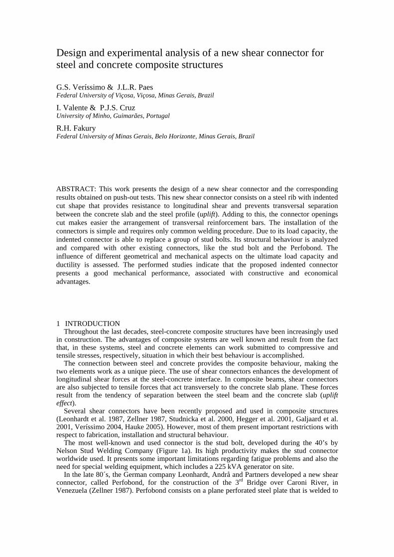
ABSTRACT: This work presents the design of a new shear connector and the corresponding results obtained on push-out tests. This new shear connector consists on a steel rib with indented cut shape that provides resistance to longitudinal shear and prevents transversal separation between the concrete slab and the steel profile (uplift). Adding to this, the connector openings cut makes easier the arrangement of transversal reinforcement bars. The installation of the connectors is simple and requires only common welding procedure. Due to its load capacity, the indented connector is able to replace a group of stud bolts. Its structural behaviour is analyzed and compared with other existing connectors, like the stud bolt and the Perfobond. The influence of different geometrical and mechanical aspects on the ultimate load capacity and ductility is assessed. The performed studies indicate that the proposed indented connector presents a good mechanical performance, associated with constructive and economical advantages.

the steel beam upper flange (Figure 1b). This connector was designed to fulfil the need of a connector that could only mobilize elastic deformations for service loads. The main disadvantage of Perfobond connector is the difficulty to position the slab lower reinforcement, when the steel bars have to cross the connector openings.
Figure 1– (a) stud connector; (b) Perfobond connector; (c) CR connector.
This work summarizes the design and tests results for the proposed shear connector, called
CR (Figure 1c). CR connector has an indented cut form that constitutes a good alternative to Perfobond connector, because it provides an easier disposition of reinforcement bars. It presents a symmetric cut, with trapezoidal saliencies and re-entrant angles, which provide resistance to longitudinal shear forces and prevent the transversal separation between the steel profile and the concrete slab (uplift). The concrete positioned inside the connector’s apertures works as concrete dowels, with a similar behaviour to the one obtained with Perfobond connectors. The experimental tests results obtained for CR connector are critically analysed and compared to the ones obtained for Perfobond and stud, regarding the maximum load capacity and the connection ductility.
Like Perfobond, CR connectors present the following advantages when compared to stud connectors: they can be large scale produced, they can assume particular forms and shapes, they are easily welded to the steel profile with no need of special equipment, and the welding task can be performed either at site or at an industrial unit. In terms of load capacity, CR connector provides equivalent resistance to a group of studs.
Several tests performed with CR connectors by the authors of this work and with Perfobond connectors by other investigators showed that both the connection load capacity and ductility are influenced by the concrete strength and the slab transversal reinforcement (Leonhardt et al. 1987, Oguejiofor et al. 1994). Therefore, it is possible to control CR connection load capacity properly choosing concrete strength and reinforcement rate. On the other hand, when stud connector failure is governed by shearing, an increase on concrete strength has only a small influence on the connection load capacity.
2 EXPERIMENTAL TESTING 2.1 Push-out tests
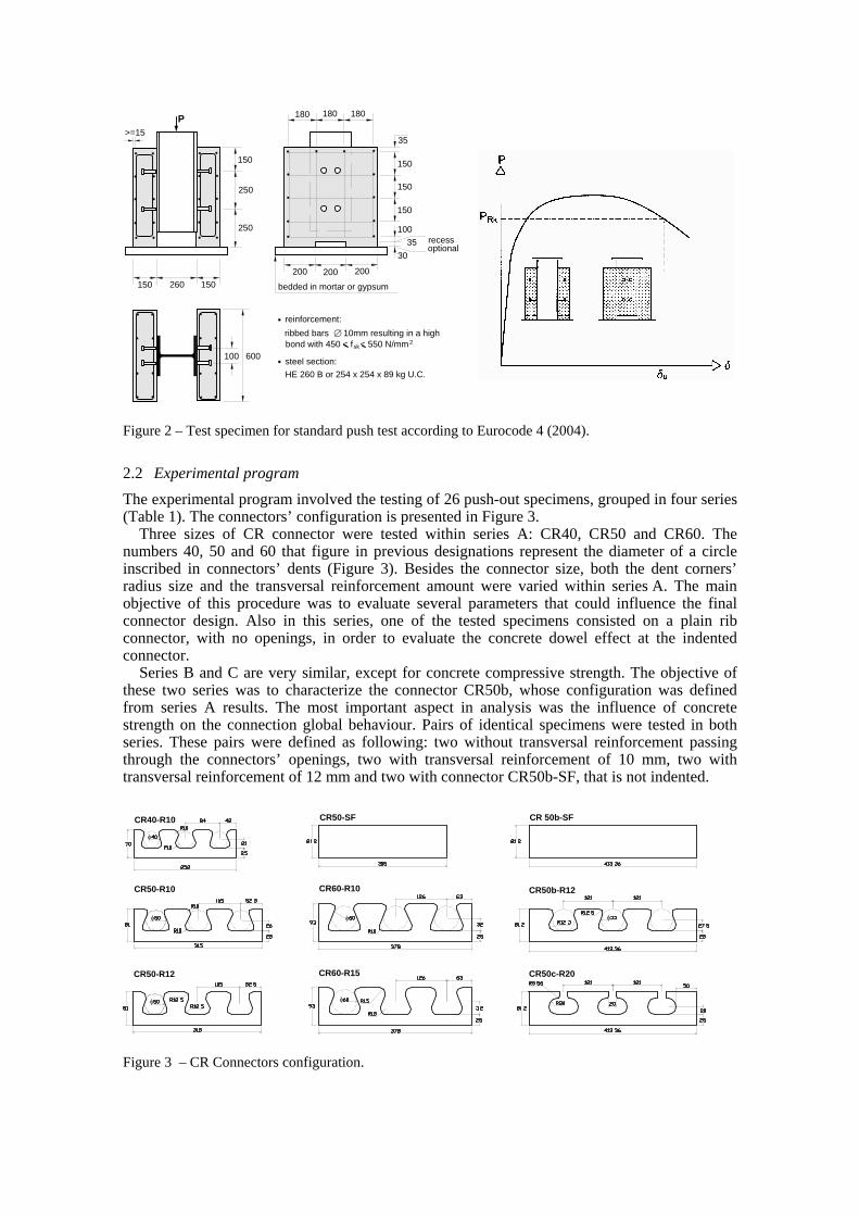
Push-out tests were used to study CR connector behaviour, in order to establish the load-slip relation. According to Eurocode 4 (2004), the push-out specimen consists on a steel beam section held in vertical position by two identical concrete slabs, as showed in Figure 2. Beside the specimen geometry, Eurocode 4 (2004) also defines the test procedure. The initial phase of the test is characterized by 25 cycles of loading and unloading, between load values of 5% and 40% of the predicted ultimate load. Following this, the test is controlled by deformation, with measurements of slip between the steel profile and the concrete slab at a constant rate. Lateral displacement between slabs is also measured. The test proceeds until failure, and slip is measured until the load value is at least 80% of the ultimate load.
The slip capacity δu, measured in a push-out specimen, should be considered as the maximum slip correspondent to the characteristic load PRk, as shown in Figure 2. The characteristic load PRk is taken as the smaller failure load divided by the number of shear connectors and reduced of 10%. The characteristic slip capacity δuk is considered equal to 0,9δu.
(a) (b) (c)
250
150 260 150
250
150
P
200200 200
100
150
3035
150
150
35
180180 180
recessoptional
bedded in mortar or gypsum
HE 260 B or 254 x 254 x 89 kg U.C.steel section:
reinforcement: ribbed bars 10mm resulting in a high∅bond with 450 < f < 550 N/mmsk
2
100 600
>=15
φ
CR40-R10
CR50-R10 CR60-R10
CR60-R15CR50-R12
CR50-SF CR 50b-SF
CR50b-R12
CR50c-R20
φφ
φ
φ φ
Figure 2 – Test specimen for standard push test according to Eurocode 4 (2004).
2.2 Experimental program The experimental program involved the testing of 26 push-out specimens, grouped in four series (Table 1). The connectors’ configuration is presented in Figure 3.
Three sizes of CR connector were tested within series A: CR40, CR50 and CR60. The numbers 40, 50 and 60 that figure in previous designations represent the diameter of a circle inscribed in connectors’ dents (Figure 3). Besides the connector size, both the dent corners’ radius size and the transversal reinforcement amount were varied within series A. The main objective of this procedure was to evaluate several parameters that could influence the final connector design. Also in this series, one of the tested specimens consisted on a plain rib connector, with no openings, in order to evaluate the concrete dowel effect at the indented connector.
Series B and C are very similar, except for concrete compressive strength. The objective of these two series was to characterize the connector CR50b, whose configuration was defined from series A results. The most important aspect in analysis was the influence of concrete strength on the connection global behaviour. Pairs of identical specimens were tested in both series. These pairs were defined as following: two without transversal reinforcement passing through the connectors’ openings, two with transversal reinforcement of 10 mm, two with transversal reinforcement of 12 mm and two with connector CR50b-SF, that is not indented.
Figure 3 – CR Connectors configuration.

HE 260N1
N2
Series X, with just two specimens, was done with the objective of evaluating the difference between the connector s’ versions CR50, CR50b and CR50c.
2.3 Specimens fabrication Push-out test specimens were built according to Eurocode 4 (2004) specifications (Figure 2). Shear connectors were welded to the steel profile by qualified welders (Figure 4a). Formwork was made out of water-resistant MDF (Figure 4c). The specimens were concreted and cured at a concrete plant and afterwards transported to the laboratory facilities. Crushed aggregate with grading in the range of 5 mm to 12 mm and a water reducing agent were used to guarantee a good concrete compaction.
Figure 5 presents the configuration of one specimen with connector CR50b and reinforcement bars passing through the connectors’ openings. These particular reinforcement bars are suppressed for some of the tested specimens.
2.4 Material properties The CR connectors used in series A were fabricated in Brazil, using 12.5 mm thick plates of USI-CIVIL 300 steel (minimum yielding strength of 359 MPa). The CR connectors used in series X, B and C were fabricated in Portugal, using 12.0 mm thick plates of S275JR steel (minimum yielding strength of 302 MPa). Reinforcement bars used steel S500 (minimum yielding strength of 500 MPa).
(a) (b) (c)
Figure 4 – Details on the specimens’ fabrication.
Figure 5 - Specimen with CR50b connector and transverse reinforcement.

0
10
20
30
40
50
60
0 7 14 21 28 35 42
age in days
fc,c
il [M
Pa]
series A series X
series B series C
All series were made with normal density concrete. In series A and X concretes C25/30 and C15/20 were used, respectively. In series B and C concretes C20/25 and C35/45 were used, respectively. Figure 6 presents the concrete compressive strength evolution in time for all the concretes used within this work. Figure 6 - Evolution of concrete strength with time.
2.5 Tests setup and measuring The experimental tests were performed at the Civil Engineering Structural Laboratory, in University of Minho, Portugal.
A vertical monotonic load was applied to the specimens using a hydraulic test machine with 5000 kN capacity. The vertical slip at the steel-concrete interface was measured in two points at a regular period of time, as well as the lateral displacement of the slabs. The test setup is illustrated in Figure 7.
3 EXPERIMENTAL RESULTS The tests results are presented in Table 1. Figure 8 presents results for connectors with dents referred to a 50 mm hole.
Figure 7 - Push-out test setup.

R2 = 0,91
R2 = 0,99
0
100
200
300
400
500
600
15 20 25 30 35 40 45 50 55
fc (MPa)
load
per
con
nect
or (k
N)
w ith reinforcementw ithout dents
C6
X1B6
B3
B4 B5A4A6
C4
C5
C3
A2B7B8
C8C7
R2 = 0,89
0
100
200
300
400
500
600
15 20 25 30 35 40 45 50 55fc (MPa)
load
per
con
nect
or (k
N)
w ithout reinforcement
B1
B2A3
A5
C1
C2
Table 1 - Tests results. ________________________________________________________________________________________________________ Specimen Connector* Concrete age fc,cil R** Transverse PRk δu _____________ _______ _______ ______ ______ days MPa mm reinforcement kN mm ________________________________________________________________________________________________________ A1 CR40-R10 34 31.9 10 - 284.6 9.10 A2 CR50-SF 49 33.0 - - 174.2 10.90 A3 CR50-R10 50 33.1 10 - 304.5 12.70 A4 CR50-R10 42 32.5 10 φ 10 mm 335.0 9.00 A5 CR50-R12 47 32.9 12.5 - 276.0 11.50 A6 CR50-R12 44 32.6 12.5 φ 10 mm 332.7 7.60 A7 CR60-R10 49 33.0 10 φ 10 mm 378.9 11.10 A8 CR60-R15 47 32.9 15 φ 10 mm 389.7 9.70 X1 CR50b-R12 17 19.5 12.5 φ 10 mm 323.3 6.60 X2 CR50c-R20 15 18.0 20 φ 10 mm 305.9 6.25 B1 CR50b-R12 13 26.6 12.5 - 266.6 9.22 B2 CR50b-R12 13 26.6 12.5 - 275.8 9.30 B3 CR50b-R12 15 27.2 12.5 φ 10 mm 313.9 4.71 B4 CR50b-R12 14 26.9 12.5 φ 10 mm 338.3 6.58 B5 CR50b-R12 21 28.5 12.5 φ 12 mm 340.3 7.20 B6 CR50b-R12 9 24.8 12.5 φ 12 mm 334.6 6.15 B7 CR50b-SF 20 28.3 12.5 - 165.3 7.80 B8 CR50b-SF 9 24.8 12.5 - 159.8 11.90 C1 CR50b-R12 17 46.9 12.5 - 325.2 10.74 C2 CR50b-R12 20 48.1 12.5 - 339.8 12.32 C3 CR50b-R12 24 49.1 12.5 φ 10 mm 444.3 5.73 C4 CR50b-R12 22 48.7 12.5 φ 10 mm 456.0 7.78 C5 CR50b-R12 22 48.7 12.5 φ 12 mm 418.5 7.91 C6 CR50b-R12 15 45.9 12.5 φ 12 mm 447.2 6.77 C7 CR50b-SF 29 49.7 12.5 - 193.9 10.00 C8 CR50b-SF 26 49.4 12.5 - 195.8 9.23 ________________________________________________________________________________________________________ * CRxx-Ryy = connector with dents referred to an inscribed circle with xx mm diameter and corner radius
of dents equal to yy mm. * CR50b-SF = connector CR50b without dents. ** R = corner radius of dents
Figure 8. Results for connectors with dents referred to a 50 mm hole.
4 RESULTS ANALYSIS AND CONCLUSIONS
Figure 9 shows results of tests with CR connector carried out at Universidade do Minho, and results of tests with stud and Perfobond, executed at the University of Saskatchewan (Oguejiofor et al. 1994, Veldanda et al. 1992). It can be seen that the CR connector, like Perfobond, presents good load bearing capacity after the load peak, which does not happen with the stud connector. One CR connector presents load capacity that is equivalent to four 19 mm

0,0
50,0
100,0
150,0
200,0
250,0
300,0
350,0
400,0
450,0
500,0
550,0
0 5 10 15 20 25 30slip (mm)
load
per
con
nect
or (k
N)
X1 - CR50b-R12-As10 fc = 19.5 MPa B4 - CR50b-R12-As10 fc = 26.9 MPa
C4 - CR50b-R12-As10 fc = 48.7 MPa
0
100
200
300
400
500
600
0 5 10 15 20 25 30slip (mm)
load
(kN
)
4 studs 19mm @ 125mm fc=26.4 MPa (Veldanda, 1992)1 B4 - CR50b-R12-As10 fc=26.9 MPa 1 C4 - CR50b-R12-As10 fc=48.7 MPa 1 PB50-As10 fc=20.91 MPa (Oguejiofor, 1994)
0,0
50,0
100,0
150,0
200,0
250,0
300,0
350,0
400,0
450,0
500,0
550,0
0 5 10 15 20 25 30slip (mm)
load
per
con
nect
or (k
N)
B1 ( CR50b w ithout reinforcement ) fc=26.6 MPa
B5 ( CR50b w ith reinforcement ) fc=28.5 MPa
B7 ( CR50b w ithout dents ) fc = 28.3 MPa
0,0
50,0
100,0
150,0
200,0
250,0
300,0
350,0
400,0
450,0
500,0
550,0
0 5 10 15 20 25 30slip (mm)
load
per
con
nect
or (k
N)
C1 ( CR50b w ithout reinforcement ) fc=46.9 MPa C4 ( CR50b w ith reinforcement ) fc=48.7 MPa
C8 ( CR50b w ithout dents ) fc = 49.7 MPa
studs, for concretes in the same range of strength. For an increase of 81% in the concrete strength there is a gain of 35% in the load bearing capacity of the CR connector.
Figure 10 shows the results of identical specimens with CR50b connector, except for the concrete strength. It can be observed that the increase on the connection load capacity is proportional to 3/4 of the concrete strength increase. The variation in concrete strength has small influence in connection ductility when there are rebars passing through the connector.
Figure 11 shows the tests results with CR50b connector, using concretes C20/25 and C35/45. It can be observed that the concrete dowel effect is very significant and it is related to an increase of 66% in the connection load capacity, in despite of concrete strength. The presence of reinforcement has also an important influence on the connection load capacity, producing a 29% gain in specimens with concrete C20/25 and a 40% gain in those with concrete C35/45. This demonstrates that the increase of concrete strength leads to better exploitation of the reinforcement.
Tests done with CR connector showed that the average characteristic slip capacity was greater than the 6 mm limit specified by Eurocode 4 (2004), which confirms its sufficient ductility. It was verified that the connection ductility grows up with increasing concrete strength when there is no transversal reinforcement.
The experimental results presented in the bibliography and those obtained during this experimental program put in evidence several important differences between the indented connector, the stud and the Perfobond. These aspects are related to failure mode, maximum load applied during the test and connection deformation capacity.
Figure 9. CR connector typical behaviour in comparison with stud and Perfobond.
Figure 10. Influence of concrete strength in CR connector behaviour.
a) connection with CR50b in C20 concrete b) connection with CR50b in C35 concrete
Figure 11. Influence of dowels, concrete strength and reinforcement in connection with CR50b.

In relation to the behaviour identified for each connector type failure mode, it has been observed that studs tend to suffer shank shear failure, immediately above the weld. On the other hand, Perfobond connector does not undergo failure itself, but it tends to cause intense cracking in the concrete slabs. The CR connector presents an intermediate behaviour, since it produces concrete slab cracking associated to some visible deformation of the dents. The CR connector exhibits lower load capacity than a Perfobond connector of similar dimensions. Both Perfobond and CR connectors make it possible to improve the connection load capacity by increasing the transversal reinforcement.
Usually, CR steel rib connectors show higher stiffness for service loads than studs, in the same way that it is observed for Perfobond (Valente 2004). The difference between these connectors stiffness is considerable and it is important to emphasize that the elastic range for steel rib connectors is greater than the one observed for studs. In the same way, the slip correspondent to ultimate load in tests performed with steel rib connectors is lower than for studs. The post peak behaviour is characterized by a slower load loss. As the failure does not occur by connector shearing, the final deformation is very large.
The results obtained have shown that the choice of connector type must take into account the differences in structural behaviour and an evaluation on advantages and disadvantages of its use. These aspects will have direct influence over the structural element response for which the connector is designed and also on the type of loading imposed to the connector along its service life.
5 ACKNOWLEDGEMENTS
The authors wish to thank University of Minho, CAPES, CNPq and FAPEMIG, for supporting this work.
REFERENCES
Eurocode 4. 2004. EN 1994-1-1:2004: Design of composite steel and concrete structures. European Committee for Standardisation (CEN).
Galjaard, H.; Walraven, J.C. 2001. Static tests on various types of shear connectors for composite structures, In: International Symposium on Connections between Steel and Concrete, University of Stuttgart, Vol.2, pp. 1313-1322.
Hauke, B. 2005. Shear connectors for composite members of high strength materials. EUROSTEEL 2005 - 4th European Conference on Steel and Composite Structures, Maastricht, Vol.B, pp. 4.2-57 – 4.2-64.
Hegger, J.; et al. 2001. Studies on the ductility of shear connectors when using high-strength concrete, In: International Symposium on Connections between Steel and Concrete, University of Stuttgart, Vol.2, pp. 1024-1045.
Leonhardt, F.; et al. 1987. Neues vorteilhaftes verbundmittel für stahlverbund-tragwerk mit höher dauerfestigkeit (New advantageous shear connection for composite structures with high fatigue strength). Beton und Stahlbetonbau, Berlim, No. 12, pp. 325-331.
Oguejiofor, E. C. & Hosain, M. U. 1994. A parametric study of perfobond rib shear connectors, Canadian Journal of Civil Engineering, 21, pp. 614-625.
Studnicka, J.; et al. 2000. Perforated shear connector for composite steel and concrete beams. In: Conference Composite Construction in Steel and Concrete IV, Proceedings of the Conference Composite Construction in Steel and Concrete IV, Banff, Alberta, Canada, pp. 367-378.
Valente, I. & Cruz, P. 2004. Experimental studies on shear connection between steel and lightweight concrete, Second International Conference on Bridge Maintenance, Safety and Management, Kyoto, Japan.
Veldanda, M. R. & Hosain, M. U. 1992. Behaviour of perfobond rib shear connectors: push-out tests. Canadian Journal of Civil Engineering, n.19, p.1-10.
Veríssimo, G. S. 2004. Development of an indented steel rib shear connector for composite steel-concrete structures and study of its structural behaviour. Belo Horizonte: Universidade Federal de Minas Gerais – Structural Engineering Graduate Program. PhD Thesis Project (text in Portuguese).
Zellner, W. 1987. Recent designs of composite bridges and a new type of shear connectors. Proceedings of the IABSE/ASCE Engineering Foundation Conference on Composite Construction, Henniker, N.H., pp.240-252.