session; nuclear energy
TRANSCRIPT

fflD 710
Session;
Nuclear Energy
Wednesday, May 20,1970
1330-1800 hrs
International Power System Fairand
SYMPOSIUM
Oslo May, 19 - 24, 197O

NOR-POWER '70International power system fair
Norges VareniessePostboks 130Skoyen — Oslo 2Pnono 55 37 90
Secretariat of the Fair:Konsulentfirmaet Knut B. AndersenTorggt 10Oslo 1Phone 33 33 32 — 33 16 37
CONTENTS:
Session I I I .
Nuclear Energy.
Wednesday, May 20: 1330-1800,
1. Nuclear Power in Norway
2. The Nuclear Power Industry ofthe United Kingdom . . . . . . . . . . .
3, Swedish Nuclear ManufacturingIndustr ies - Today and Tomorrow . . .
4. Technology and Economics of NuclearPower Plants Constructed by Kraft-werk Union in Germany and Abroad . . .
Mr. Henrik Ager-Hansseu-Institute tor Aton-.energi ,Norway.
Mr. S.A. Ghalib,The Nuclear Power GroupUnited Kingdom.
Mr. Lars Halle,Asea-Atom, Sweden.
Dr. Hans Frewer,Kraf twer-k Union , B • R. D.
Oslo ISth May—24th of May 1970

Session:
Nuclear Energy
N U C L E A R P O W E R I N N O R W A Y
b y
M r . H e n r i k A G E R - H A N S S E N ,
Institutt for Atomenergi,.
Norway.
International Power System Fairand
SYMPOSIUM
Oslo May, 19 - 24, 1970

NUCLEAR POWER IN NORWAY.
Based on energy balance studies recently performed for the Nor-wegian power grid it can be concluded that introduction of nuclearpower might be economically justified around 198 0. The exacttiming is dependent on the following factors:
(1) The development of the electric energy demand
(2) The development of the capital cost differentialbetween hydro power and nuclear power
(3) The "return on capital" reauirements (interest rate) forinvestments in the power sector, and
(4) The possible future restrictions which will be put on thedifferent electric energy generation svstems due to3nvironmental renuirements
Experience abroad indicates that it takes from 8 to 9 vears toplan and construct a nuclear power station. Thus if < : shouldbe economically justified to have a first nuclear pow..' stationin operation by 1978/79, it would be necessary to stfiL theplanning work already this vear. A final decision on construc-tion, however, could wait until 1972/73. In order ^o secure thatsuch a timeschedule could be kept, one has decided to proceedwith the plans for a first nuclear power station on the basis ofcommercial operation by 1978/79.
This paper briefly describes some of the problems and perspectivesconnected with the introduction of commercial nuclear power inNorway and what is being done to deal with these challenges.
1. PLANNING, LICENSING, CONSTRUCTION AND OPERATION OF NUCLEARPOWER STATIONS IN NORWAY.
The problems in connection with the introduction of r.uclear powerin Norway are in many ways enhanced by the fact that «)e do not ha^'eany tradition in conventional thermal power. On the ether hand,the late introduction of nuclear power makes it possible to benefitfrom the experience of other countries in the planning, licensing,construction and operation of nuclear power stations. .'It is con-sidered a very important task to collect, systematize and adaptto Norwegian conditions the information from such experience.
1.1. Choice between Reactor Technologies.
The choice of reactor type for the first nuclear power station isa more complicated matter in a small than in a large country. Thelimited engineering capacity which is available in a small countrymakes it difficult to build up the necessary expertice for intro-ducing of widely different reactcr technologies, making the firstchoice much more of a commitment to be given technology than is thecase for a country with more extensive resources.
The economic merits of different reactor types, as they are exposedin a given tender evaluation, must be expected mere to reflect theeagerness of the different reactor suppliers to bid in a particularcircumstance than the real economic potentials of the different types.
HAH/1

Thus it becomes very difficult to make the reactor choice on astrictly economic comparison and other factors such as develop-ment potential, future siting flexibility, environmental implica-tions and "introduction" effort must also be considered. Thechoice of a reactor type for the first nuclear power stationshould be looked upon from the point of view of starting anuclear power construction programme and an attempt should bemade to compare the cost and benefits of the different reactortypes in respect to that programme.
For the Norwegian situation, with a nuclear power programme start-ing around 1980, the following reactor families must be considered:
- Light water reactors
- Gas cooled reactors
- Heavy water reactors
- Fast breeder reactors
The light water reactors can be considered as belonging to the samereactor technology and the development of gas cooled reactors seemto indicate that we by 198 0 probably shall have to consider onlythe high temperature type,
Heavy water moderated reactors with different coolants are beingdeveloped. Each of these represents from an engineering point ofview a different technology. There are strong indications that thespreading of the global development effort on too many heavy waterreactor versions has reaped the possibility for the heavy waterreactors ever becoming economically viable. There has, however,over the last years been a reduction in the types that seriouslyneed to be considered. It is an interesting observation that theseare the types that show a strong technological inheritance fromthe light water reactors, namely the light and heavy water cooledversions of the pressure tube types and the pressure vessel heavywater moderated and cooled type.
Although both sodium cooled and gas cooled versions of the fastbreeders are being developed, the size of the development effortstrongly favours the sodium cooled type. The target start-updates for the first commercial breeder reactors vary from around1980 to late in the 80-ties in the countries leading the develop-ment work. It is fair to assume that some positive operatingexperience will have to be demonstrated before major commitmentsto this reactor type can be expected in other countries. Suchexperience should start to become available from prototypes fromthe early 70-ties.
1 •2. Project Studies for Nuclear Power Plants in Norway
The study of the technical and economical problems related to theintroduction of nuclear power in Norway has since 1966 been thesubject of a cooperative effort between the Norwegian HydrologicalResources and Electricity Board (NVE), Norsk Hydro A.S. andInstitutt for Atomenergi. The purpose of the project is toassess capital, fuel and generating costs of nuclear power plantsunder Norwegian conditions, to consider the siting problems andto start the building up of a competance in architect engineering
HAH/2 HAH/3

and construction management for future nuclear power stations.
t-•ed:
same3 emT
5fthe:er
lese
/y
e
al
.s
g
The first part of the study, involving a detailed assessment of thelight water boiling reactor (BRW) and the advanced gas-cooled reactor(AGR), has recently been completed. The two reactor types wereselected only as representatives of their respective technologiesand should not be looked upon as reflecting a preference. The workis now being continued with different reactor types.
Two alternative sites have been considered for the study. Bothsites are located at the coast, but while standard plant lay-outsare feasible for one of the sites (the open site), the othernecessitates an underground construction in rock (the cave site).Because of the particular topology of Norway, this latter possibili-ty of future nuclear plant siting is very interesting. Moreoverthere is a considerable experience in Norway in locating hydro powerstations in rock caves.
Plant assessments for the BWR and the AGR have been worked out forboth the open site and the cave site. Thus altogether four projectshave been carried out. The necessary information on component andsystem specifications have for the BWR been obtained from the reactormanufacturers and for the AGR through an agreement with tha UnitedKingdom Atomic Energy tAiithority.
In addition to the detailed plant lay-outs, the project studies in-cluded assessments of plant and site safety and of the fuel manage-ment and operation under the conditions imposed by the Norwegianpov/ar grid.
Figures 1 and 2 illustrate the cave site plant arrangements visualizedfor the BWR. As can be seen from the figures, the reactor and theturbine generator are placed in one large cave with the control andinstrumentation and service section placed in a smaller separate andparallel cave.
As will be apparent from figure 2, the safety of the plant does notin any way rely on the rock/cave structure in that a conventionalBWR pressure suppression system has been applied. Although thissolution was adopted for the reference design, we are now studyingplant arrangements which take more advantage of the rock/cavestructure than in the reference case. The study has been broadenedto include an assessment of the PWR located in a rock cave.
The difference in the generating cost for a BWR and an AGR underNorwegian conditions has been found to be small, and it is assumedthat it lies within the tolerances that one must accept in the costdata upon which the study was based. Only firm quotations will makea choice between these reactor types possible.
The results of the economic evaluations are indicated in the followingtable and refer to a 522 MWe BWR with a startup in 1978, The approxi-mate costs are given for a day site and a cave site. The costs arebased on a 7% interest rate, 25 years amortization, a purchase taxof 13.64% and using the 1969 monetary value.
HAH/3

Day Site Cave Site
Total capital cost(including first fuel Mkrcnarge)
882
Total fixed cost
Variable cost
kr/kW year
0re/kWh
172
0.75
Generating cost
908
177
0.75
LoadLoadLoadLoad
5,6,7,8,
000000000000
h/yearh/yearh/yearh/year
0re/kWh0re/kWh0re/kWh0re/kWh
4.23 = 63.22.9
4.33.73.33. 0
The studies so far indicate that underground siting in rock is afully realistic technical proposition and that with such sitingit should be possible to further improve the safety of nuclearplants and in particular with respect to civil defence requirements.
An assessment of the possible role of the fast breeder reactor in anuclear power programme in the 80's has also been started under acooperation agreement recently entered into between the United King-dom Atomic Energy Authority (UKAEA) and IFA. Under this agreementUKAEA supplies all the. necessary information on the predictedperformance of the sodium cooled fast breeder to make it possibleto evaluate the economical merits of alternative reactor strategies,involving different combinations of thermal and fast reactors. Acooperative small scale research effort in. fast reactor instrumenta-tion is also being considered.
1-3. Licensing of Nuclear Power Stations
The absence of a demand for nuclear power has made it unnecessary toestablish firm licensing criteria for nuclear rower plants up to thepresent time. This has made it possible to gain from the experienceobtained in other countries without prematurely establishing a rigidlicensing system.
Meanwhile a nuclear power law providing a reference frame for establish-ing the licensing system and requirements has been drafted by a com-mittee set up as early as in 1957. A nuclear power low proposal is nowbeing prepared by the Department of Industry and it is expected to besubmitted for approval by the Parliament late this year. "
On the basis of the hypothesis that it should be feasible to start upthe first nuclear power station by 1978/7 9 it will be necessary tonave established a firm licensing procedure by 1971/72.
Up to the present time the licensing of nuclear research installa-th°s\aS T ! h a ^ . b ? e n considered on a case by case basis. AlthoughS™<= t V7o"kfd satisfactorily, for the different research installa-tions (e.g. three research reactors, a power test reactor, a reprocess-
1.5.
HAH/4 HAH/5

ing facility) of Institutt for Atomenergi, a commercial nuclearprogramme will require a much more elaborate procedure for securinga proper balance between safety and economics.
1.4. Engineering and Production
Development and marketing of complete nuclear power stations hasproven to be a task only for the most technically developedcountries and in these countries only extremely large firms orgroups of firms have shown the capability to survive. Engineering,components and subsystems for nuclear power stations do, however,represent a very interesting industrial involvement and where alsothe smaller countries and the smaller firms can take part.
The experience in Norway in engineering and construction manage-ment of hydro power stations and chemical and electro metallurgicalfactories coupled with the reactor technological experience atInstitutt for Atomenergi, should provide a broad basis for theindustrial involvement in the engineering and construction .manage-ment of nuclear power stations. The tendency to move away fromturn-key contracts for nuclear power stations makes it necessaryto either develop this capability for overall project, managementin Norway or to cooperate with a foreign engineering firm.
Based on the research and development in fuel reactor technologyat Institutt for Atomenergi, a background exists for industrialinvolvement in fuel fabrication. Although it will take some timebefore a Norwegian nuclear fuel market can support a viable domesticfuel production line, fuel fabrications is an interesting possibilityfor industrial involvement which is being studied. One Norwegianfirm, A/S Raufoss, has recently established a product line forzirconium tubing. The development work in this connection is carriedout in cooperation with Institutt for Atomenergi.
An assessment of which components of a nuclear power station can bemade in Norway has recently been performed as a cooperation betweenNoratom-Norcontrol A/S, Institutt for Atomenergi, and a number ofNorwegian firms. This assessment concluded that it is technicallyfeasible to produce between 50 and 60% without expansion of presentproduction facilities. The study has been instrumental in identifyingthe areas where the quality control requirements and procedures differfrom what is normally applied for conventional equipment.
ilish-i -
i nowbe
up
>ugh
:ess-
1.5. Fuel Management Problems
The operating time of the first nuclear power plants in Norway willmost likely vary considerably from year to year because of theirincorporation in a grid system dominated by hydro-electric power.This is illustrated in Figure 3 which shows'from computer studiesthe variation in yearly use time which can be expected because ofthe variations in the yearly precipitation. The requirement ofeconomic optimal use of fuel will thus, especially in the case ofthe water reactors, demand other fuel management schemes than thosewhich are normally worked out by the reactor supplier. The changingof fuel must always be adjusted to the prevailing conditions and itis necessary to consider the operating history of the reactor andthe demand of the power grid system.
HAH/5

In the case of the BWR a method has been developed at IFA fordoing this which may be applied throughout the l ife of the entireplant. Calculations have shown that this can result in savingsfor the order of 4 - 7 Mkr per year in fuel costs for a 500 MWeunit in relation to a direct application of the reactor manufactu-rer ' s standard procedure for fuel changing
2 . REACTOR TECHNOLOGICAL WORK AT INSTITUTT FOR ATOMEKERGI
The work at Institutt for Atomenergi is divided in tha following7 main sectors:
- Power reactor technology
- Fuel technology
- Process control and instrumentation
- Safety and education.
- Isotop technology
- Process chemistry
- Basic physics research
The first three of these sectors, power reactor technology, fueltechnology and process control and instrumentation account forapproximately 65% of the Institute's budget. The yearly budgetwithin these sectors at Kjeller and in Halden is approximately3 0 Mkr of which approximately 2 0 M.kr is financed by govern-mental funds a;.d approximately 10 Mkr. is financed by inter-national participation in the Institute's research and develop-ment projects. In the following a brief account cf the workbeing performed within these sectors is given.
2.1. Power Reactor Technology
The main research and development projects in this sector are:
(1) Reactor core calculational models and fuel managementprocedures
(2) Reactor shielding
(3) Reactor auxiliary systems engineering
(4) Operation and maintenance of the Halden Heavy WaterBoiling Reac'..or
(5) Various cooperative Nordic projects
Institutt for Atomenergi is developing a complete core analysiscapability to deal with the future safety, operational and econo-mical problems associated with the licensing, economic assessmentand operation of nuclear power stations. This work is directed atuhe future interests of both the owners/operators of nuclear powerstations as well as the licensing authorities. It is a recognizedfact that to deal with these interests it is necessary to build upan expertice in core analysis which comes close to that of thereactor supplier.
The woriry systethe reacconstruestudiedinstrume
The Halean excelclose tcand dev«since l£agreemexvides fcto 1972.tion, oroperaticimposedreview ithe assctunity cinvolved
Norway ;investiccooled iSweden.vessel 1anotherin USA.workingof read
2.2. Fj
The maildevelopifuturereactorpurpose
- A sma
- The H
- A hot
The tesJuly 19year prDenmarkKingdomgreat frriateriairradia
- Test
- Demon
HAH/6 HAH/7
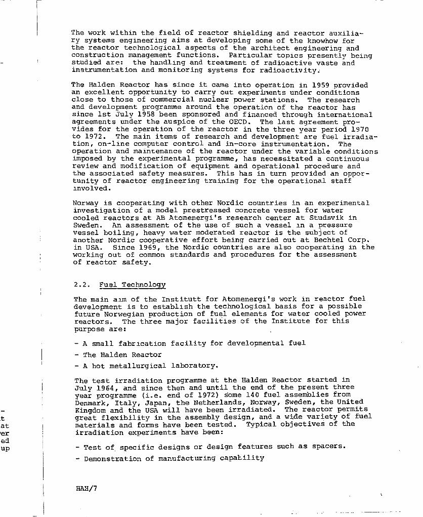
The work within the field of reactor shielding and reactor auxilia-ry systems engineering aims at developing some of the knowhow forthe reactor technological aspects of the architect engineering andconstruction management functions. Particular topics presently beingstudied are: the handling and treatment of radioactive vaste andinstrumentation and monitoring systems for radioactivity.
The Halden Reactor has since it came into operation in 1959 providedan excellent opportunity to carry out experiments under conditionsclose to those of commercial nuclear power stations. The researchand development programme around the operation of the reactor hassince 1st July 1958 been sponsored and financed through internationalagreements under the auspice of the OECD. The last agreement pro-vides for the operation of the reactor in the three year period 1970to 1972. The main items of research and development are fuel irradia-tion, on-line computer control and in-core instrumentation. Theoperation and maintenance of the reactor under the variable conditionsimposed by the experimental programme, has necessitated a continuousreview and modification of equipment and operational procedure andthe associated safety measures. This has in turn provided an oppor-tunity of reactor engineering training for the operational staffinvolved.
Norway is cooperating with other Nordic countries in an experimentalinvestigation of a model prestressed concrete vessel for watercooled reactors at AB Atomenergi's research center at Studsvik inSweden. An assessment of the use of such a vessel in a pressurevessel boiling, heavy water moderated reactor is the subject ofanother Nordic cooperative effort being carried out at Bechtel Corp.in USA. Since 1969, the Nordic countries are also cooperating in theworking out of common standards and procedures for the assessmentof reactor safety.
2.2. Fuel Technology
The main aim of the Institutt for Atomenergi's work in reactor fueldevelopment is to establish the technological basis for a possiblefuture Norwegian production of fuel elements for water cooled powerreactors. The three major facilities of the Institute for thispurpose are:
- A small fabrication facility for developmental fuel
- The Halden Reactor
- A hot metallurgical laboratory.
The test irradiation programme at the Halden Reactor started inJuly 1964, and since then and until the end of the present threeyear programme (i.e. end of 1972) some 140 fuel assemblies fromDenmark, Italy, Japan, the Netherlands, Norway, Sweden, the UnitedKingdom and the USA will have been irradiated. The reactor permitsgreat flexibility in the assembly design, and a wide variety of fuelmaterials and forms have been tested. Typical objectives of theirradiation experiments have been:
- Test of specific designs or design features such as spacers.
- Demonstration of manufacturing capability
HAH/7

- Determination of effects of varying parameters such aspower density and fuel canning gaps.
The assemblies are usually heavily instrumented, with as many as46 signals per assembly. Most of the necessary instrumentationhas been developed at the project.
The Institute's part of the work in connection with the cooperationwith Raufoss A/S on zirconium tubing is concerned with the study ofthe influence of the production variables on the metal structure andproperties and the development of procedures for quality control.Irradiation of samples in the Halden Reactor is an integral partof the programme.
2.3. Process Control and Instrumentation
The complexity in optimising the operation of a nuclear power stationensures that future stations will utilise digital computers for somedegree of operator advice or direct control. Such systems are al-ready in operation at reactors around the world. To obtain themaximum benefit from computer systems, however, research is necessaryto define the potential and limitations of such systems, and todevelop the appropriate computer techniques. The Halden Reactorprovides an excellent facility for a programme in this field, sincethe plant has the complex systems characteristic of commercial powerreactors and has no load commitment.
Research in computer control was initiated in 1967, with the purchaseand installation of an IBM 1800 process computer system. The systemwas delivered with the software necessary for the basic operation ofthe computer, but all problem-oriented software is prepared by theProject staff.
Data logging and monitoring functions were the first functions deve-loped, in order to gain experience with the computer. The computermonitors and logs the principal plant signals every few minutes,and prints summaries at 8-hour and 24-hour intervals. It also moni-tors the critical signals from test fuel assemblies every 5 minutesand logs all signals every hour.
The implementation of direct digital control functions on the computerdemonstrated the need for expanding the computer facilities and a newprocess computer, NORD-1, manufactured by the Norwegian firm NORDATAhas been installed.
The main development work on instrumentation at the Institute hasbeen directed towards instruments with the following functions:
- Experimental determination of the real limits on corepower to eliminate undue conservatism
- Continuous monitoring during operation, so that the limitscan be approached closely but not exceeded.
Most of this development effort has been carried out at the HaldenReactor and a basic set of instrumentation has been developed todetermine the operating characteristic of the natural circulationfuel channels. Turbine flow meters are used to measure the inlet
HAH/8

water velocity and the exit water/steam flow rate. Channel power-LS determined by gamma thermometers, or alternately by neutronsensitive detectors such as beta-current detectors or neutrontherr.omet er s,
Examples ot other instruments which have been developed and appliedm-core are
- Pressure transducers to measure the building of fission gaspressure inside the fuel cladding
- Differential transformers to measure the elongation of thefuel canning
- Burn-out detectors to detect, cladding overheating if thecri t ical heat transfer conditions are exceeded
- Impedance void gauges for the measurement of transient voidtract ions
The development of the above instruments has been quite essential tothe fuel irradiation and the on-line computer control programmes.Where chere has been a demand for large series of any of the instru-ments, the manufacturing has been taken over by Norwegian firms.In particular Noratorn - Morcontrol A/S and Kongsberg Vapenfabrikkh^e been involved in their development and production.
HAH/9

1 REACTOR SECTION
2 CONTROL AND ELECTRICAL SECTION
3 TURBO GENERATOR SECTION
4 OUTDOOR BUILDING, TECHNICAL SECTION
5 OUTDOOR BUILDING, ADMINISTRATION AND WELFARE
6 STACK
7 SWITCHYARD
STATION LAYOUTBWR CAVE SITE FIG.t

123U56789
101112
REACTORPS - POOL
CONTAINMENTSPENT FUEL POOLFEED WATER PUMPTURBINE
GENERATOR
MAIN CONDENSER
MAIN COOLING WATER PUMP
CONDENSATE POLISHING PLANT
WASTE TREATMENT PLANTWASTE STORAGE
. ' I ' •'
REACTOR AND TURBINE HALLBWR CAVE SITE
'FIG. 2

8760
o
o7008
5
6390
5256
3504
100
£
ud
70
50
I
Productionsystem
HYDRO
NUCLEARThermal
Fast breeder
OIL
GAS-TURBINES
Installedcapucity
6 8 % •
5 V.
—
6 V.
IV.
Variable costore/kWn
0.65
—
2.7
A
10 15 20Years
25
30
20
10
30
TYPICAL LOAD DEMAND VARIATIONS FOR A THIRTY YEAR
SEQUENCE FOR THE FIRST NUCLEAR POWER STATION.
HAH/03
I
The : - i - ' -."
reck cavr r .
used as r rc
HAH/Oil
:••.•: \-:l; f a c t - :

•1)9
Session:
Nuclear Energy
T H E N U C L E A R P O W E R I N D U S T R Y
O F T H E U N I T E D K I N G D O M
by
Mr. S.A. G H A L I B ,
The Nuclear Power Group,
United Kingdom.
International Power System Fairand
SYMPOSIUM
Oslo May, 19-24, 1970

THE 1 JCLEAR POWER INDUSTRY IN THE UNITED KINGDOM
1. INTRODUCTION
In the early days of nuclear power in the U.K. research and developmentwas concentrated through the Atomic Energy Author icy or. a narrow front, inorder to apply the new technology as rapidly as possible to meet thenational needs for economic generation of electricity. This policy wascrowned wirh the early construction of gas cooled reactors. As a result,today we are generating 57% of the world's nuclear powe-, with availa-bility figures of 7Q%-80%.
Later, the research and development front was broadened, with growingindustrial participation, to cover advanced and higher temperature gascooled reactors, the Steam Generating Heavy VJater Reactor, and theSodium Cooled Fast Reactor. An experimental Past Reactor has beenoperating for eight years. A 100 MW SGHWR has been operating for overtwo years. A 25 3 MW prototype Fast Reactor is under construction andis due to be completed in 1972.
2. STRUCTURE OF THE NUCLEAR POWER INDUSTRY
2.1. Reactor Design and Coi struction teans
In every country where nuclear reactors have been developed a very largepart of the cost has been paid out of public funds. The extent of colla-boration between governmental bodies concerned with atomic energy and theindustry, and the degree of control exercised by governments, vary widely.In U.K., the Atomic Energy Authority was set up with the responsibilityfor de/eloping reactor systems and demonstrating their feasibility, safetyand economics. For this purpose extensive research establishments and testfacilities were built up, including research and test reactors, and "hot"laboratories. The AEA's own staff designed the complete reactor systems,and employing contractors, built prototypes. Although the responsibilitywas theirs, the AEA encouraged the involvement of industry in the concep-tual design of reactors. In this way, the industrial groups that wereset up for the commercial exploitation of nuclear power became familiarwith every aspect of the new technology at an e.arly stage.
The involvement of industry led to very close collaboration between theASA, the Generating Boards, and the industrial nuclear design teams. Thedegree of collaboration is probably unique in any country.
The formal collaboration between the parties starts with a ReactorPolicy Committee, a consultative body, on which the parties cire representedby senior staff. Ail matters of common interest, particularly the broadline? of development policy, are discussed. The Committee is supportedby many working parties, which discuss the details of the research anddevelopment programmes in their own areas of interest AJ&J receive progressreports from the various laboratories. All irradiation work is carriedout by the AEA, but metallurgical and engineering work is placed where itcan be carried out most expeditiously. Irrespective of where the workis carried out, or who initiates it, the AEA pay the cost of developmentnecessary to prove the feasibility and safety of new reactor systems.The cost of generic work to improve the breed is shared by the AEA andthe industrial groups.
wl-isft
SAG/1

This extensive and close collaboration covers the basic problems of reactorsystems but not engineering designs, on which there is keen competition bet-ween the industrial teams who have their own development programmes insupport of their particular designs. This work is carried out privatelyand paid for by the Groups ard not disclosed to each other. In this way,on the one hand, it has been possible to make rapid progress with reactortechnology by concentrating the country's resources on common problems,and on the other, the Generating Boards have had the benefit of technicaland economic competition between the contractors.
Up to now the AEA's reactor designs team has been fully occupied designingand constructing a series of test and prototype reactors. We are nowapproaching the end of what might be called the prototype reactor era.In the foreseeable future, there does not appear to be a completely newreactor system with sufficient economic incentive to justify the develop-ment and construction of a prototype. The relatively small number ofexperienced engineers of high calibre involved could, of course, be em-ployed on entirely different projects, but their skills and know-how wouldbe lost to the nuclear power industry. The government, after giving care-ful consideration to this and other related problems, decided on a newstructure for the industry. Briefly this is as follows:-
The nomber of industrial Design and Construction Companies licensed toexploit power reactors commercially has been reduced to two. At varioustimes there have been four, five, then four again, and more recentlythree industrial organisations with such licences.The volume of businesswas not sufficient to keep so many teams viable. There were suggestionsfrom some quarters for reduciNg the teams to one. This would have madecompetition in design impossible and was not accepted by the government.
In parallel with the reorganisation of the reactor Design and Constructioncompanies, the power plant manufacturing industry has been undergoingchanges. In the U.K. there are now only two turbine generator companies,each one associated with a Design and Construction company. There arethree boiler companies in the nuclear field. One of them is associatedwith one of the Design and Construction Companies, and two of them, incollaboration, with the other.
The AEA have a 20% shareholding in each of the Design and ConstructionCompanies, Also, for the time being, the government through the IndustrialReorganisation Corporation, have 10% holding in one Company and 26% inthe other. The shareholders in the two companies are shown in Table 1.
An AEA team, numbering approximately 140, engaged in the design and con-struction of the Prototype Fast Reactor at Dounreay, has been transferredto one of the industrial Companies. This company now has a contractfrom the AEA to complete the design and construction of the PFR. To putthe extent of the transfers from the AEA into the right perspective, itshould be noted that the total number of professional staff in the AEA isapproximately 4,500. The large body of scientific and research workersstill remain in their own establishments. However, the transfer of thefunctions of the relatively small design team to industry is very signi-ficant and has far-reaching effects. Up to now 'it was the AEA's reactordesign team that largely determined, after consultation with the Designand Construction Companies, the broad lines of advanced designs and theresearch and development programmes necessary to substantiate new designs.But the responsibility for producing commercial designs and exploitingreactors was not theirs. There was thus a split responsibility. In thefuture the Design and Construction Companies will be responsible for deter-mining the research and development programmes, as well as for the commer-cial exploitation of reactors. Most of the research and development workwould still be carried out in the AEA's establishments. If the work is paid
for by aa normalIf publicstructioiposal byfrom thethe AEA,advise ti
As a resihave beeito the cipractical
0 9 pi
So far a.and repnthe Atoman indusInitiall;but evencompanietunity tDesign aNuclearBoard.supplier
2,3 Nu
After thductionsional smind to1,450 prto formnuclearnuclearAtomic E
3. BRI1
It is pageneratdThe exp]which irand in tGenerateprovideda numbeimedicalcontribiIn 1965presentBritishreactormeans o:these c(
As a meiin sett:
SAG/2 SAG/3

reactorion bet-
: initely.s way,:actor.ems,mical
signing>W
sra.newrelop-jfem-
; wouldj care-new
torious
inessstionsmade
inent.
ruction-ngjanies,i are.atedan, in
:ionldus t r i a l>% in.e 1.
1 con-sferredictPo put2, i t2 AEA issrkersjf thesigni-sactor)esignid thelesigns.iingIn the
3r deter-commer-it workc is paid
for by a Design and Construction Company, then it will be handled asa normal commercial contract by the AEA and treated as confidential.If public funds are involved, however, then both the Design and Con-struction Companies will have access to the results. There is a pro-posal by the government to set up an Atomic Energy Board with membersfrom the Design and Construction Companies, the Generating Boards, andthe AEA, to decide the joint research and development programmes and toadvise the government on their size and shape.
As a result of the reorganisation, the Design and Construction Companieshave been streamlined and made more effective to take prototype designsto the commercial stage and to continue to improve such designs based onpractical experience.
2.2 Fuel Services
So far all the processes involved in nuclear fuels, including enrichmentand reprocessing, have been the responsibility of the Production Group ofthe Atonic Energy Authority. The government are now proposing to set upan industrial company to take over the functions of the Production Group.Initially, all the shares in the Company will be hexd by the government,but eventually the Design and Construction Companies and other industrialcompanies with interest in reactor plant and fuel, will be given an oppor-tunity to purchase minority shares. The 20% shareholding by the AEA inDesign and Construction Companies v/ill eventually be transferred to theNuclear Fuel Company, which will also have a member or. the Atomic EnergyBoard. In this way, the ties between the reactor designers and the fuelsuppliers will be further strengthened.
2,3 Nuclear Research and Development Laboratories.
After the formation of the Nuclear Fuel Company, by hiving off the Pro-duction Group from the AEA, there will still be left about 3,200 profes-sional staff, with exellent research facilities. The government have inmind to combine these resources and manpower in the AEA with approximately1,450 professional staff in other national research establishments andto form a British Research and Development Corporation, to undertakenuclear and non-nuclear work for the government and for industry. Thenuclear research and development programmes would be decided by theAtomic Energy Board
3. BRITISH NUCLEAR FORUM
It is paradoxical that a country which has the largest nuclear powergeneration has one of the youngest and smallest industrial nuclear forums.The explanation xies in the constitution of the industrial consortia,which included the majority of the companies interested in nuclear plant,and in the close collaboration between the consortia, the AEA, and theGenerating Boards. The many working parties set up by these organisationsprovided a forum for discussion of all subjects of mutual interest. However,a number of industrial, professional, financial, legal, insurance, andmedical organisations interested in nuclear matters and able to make acontribution to the general progress of the industry were not represented.In 1965 there was sufficient suppwt to form a national Nuclear Forum i«-r&-present all the interested parties. During the last few years theBritish Nuclear Forum has been successful in bringing together overseasreactor designers and British equipment and component manufacturers bymeans of inward and outward missions, conferences and exhibitions. Throughthese contacts mutually beneficial business has resulted.
As a member of Foratom, the British Nuclear Forum played a leading partin setting up a European industrial team in Brussels to study the Gas
SAG/3

Cooled Fast Reactor. This is perhaps the first time such an organisationhas been set up, albeit small, supported entirely by private companies. Ifthe results of the study now being carried out are promising it is hopedto persuade some of the European governments to support financially theconstruction of a fuel test bed reactor.
4 . THE CURRENT NUCLEAR POWER PROGRAMME
A.G.R.
Following the successful construction and operating of the gas cooled reactorusing natural uranium/magnox fuel elements, a higher temperature version ofthis reactor, using enriched uranium oxide/stainless steel fuel elements,that is J_he A.G.R. , has been adopted as the basis of the second nuclear powerprogramme by the Generating Boards. See Table 2. Four twin-reactor stationsare now under construction. Each reactor is coupled to a single conventionalturbine generator set of 660 MW gross output. Three of these stations,Dungeness "B1, Hinkley Point "B'; and Hunterston 'B' are in an advancedstage of construction. It is reassuring that neither the developmentof the designs in detail nor the construction of the reactors has shownup any serious nuclear problems and difficulties to delay the programmeas a whole. There is some delay at Dungeness 'B' due to unfortunate mis-haps with the steel work., not connected with the reactor core, but theHinkley and Huntarston stations are on schedule.
The Central Electricity Generating Board have plans ro construct tv.o moreAGR stations, at Heysham and Sizewell. Work on these is expected to commencethis year and next year respectively. They have also announced plans tobuild nuclear power stations at Connah's Quay, Stourport, Portskewett, andOldbury 'B'. All these, with the possible exception of Oldbury "B1 'asexplained later, will be AGR' s. The current programme, with Heysham and jSizewell, represents an investment by the Generating Boards of about !£650 million and demonstrates their condidence in A.G.R.
It is interesting to reflect on this, as the majority of the world's utili-ties are installing light water reactors. This is largely because the firstcost of these reactors" is less than that of the A.G.R. It is a fairlysimple matter to evaluate the generation cost of a reactor system usingquoted prices for the plant and fuel; but this is an elementary approach.A more sophisticated evaluation involves detailed assessment and engineeringjudgement of the reliability of each component and hence the availability ofthe plant year by year during its lifetime and the cost of maintenance toachieve these levels of availability. The Generating Boards in the U.K. .with highly qualified staffs experienced in reactor technology have made suchassessments and have come to the conclusion that in 600 MW units theA.G.R. will gener.'.te electricity, over its lifetime, as economically asany reactor system available commercially today. Furthermore, the operatorslike the on-loarf refuelling feature of the A.G.R., which makes its operationmore flexible and avoids the problems of having to plan the shut-downperiods accurately a long time ahead, which is necessary with light waterreactors. With batch refuelling, the enrichment of the replacement fuelhas to be decided a year or mere in advance, and the number of MW hoursoperation of the reactor subsequently has to match the enrichment chosen.
S.G.H.W.R.
In the early 1960s it was decided to develop water reactor technology in theU.K. as an insurance policy in the event of serious unforeseen difficultieswith the A.G.R. Making use of the information and experience availableat the time on light and heavy water reactors, the Steam Generating HeavyWater Reactor was evolved. A 100 MW prototype was built, using precisely thesame parameters for the critical components, such as the pressure tubes
SAG/4
and fuel <has been ojto operatebuilt usiniproven des.
Refuellingis direct .much quickfuelling,such a perto refuel :
The CEGB cstations igenerationof their cthat a morbe availabchange ove
The abovenuclear postalled athe S.G.H.
The econoitisizes. Itunits of 1
H.T.R.
A logicalsearch arover threecoated fueare tentaiabout thestudies dc
Sodium Co(
As mentioiresponsib!is expect*experienciconstructof this t;in converearly assider buibased on
SAG/5

If>ed
reactorIon ofits,ar powerstationsentionals,ed
wnmmemis-
morecommences toand
sand
utili-le firstLi''Lngroach.jineeringLlity of;e toJ.K. .aade such
Ly asperatorsoperation
«iwaterfuel
Durs3sen.
{ in the
DieHeavy
sely thejbes
and fuel elements, as would be used in a large reactor. The prototypehas been operating satisfactorily and has proved to be particularly easyto operate, and able to follow load changes. Any size reactor can now bebuilt using the right number of pressure tubes and fuel elements of theproven design.
Refuelling is carried out with the reactor shut down. But because thereis direct access to each tube and fuel element assembly, the operation ismuch quicker than with light water reactors. With six-monthly batch re-fuelling, the reactor need not be shut down for more than 50 hours. Wheresuch a period of shut down cannot be accepted, it would be possibleto refuel more frequently during weekends.
The CEGB carried out an economic comparison of A.G.R. and S.G.H.W.R.stations in 2 x 600 MW sizes. They came to the conclusion that thegeneration cost of the S.G.H.W.R. would be about 5% cheaper but becauseof their considerable experience with gas cooled reactors, and the factthat a more economic version of this type of reactor - the HTR - mightbe available in a year or two, it would not be desirable for them tochange over to the S.G.H.W.R.
The above argument does not apply to an electric utility contemplating anuclear power station for the first time, or to one that has already in-stalled a light or heavy water reactor, as the technologies of these andthe S.G.H.W.R. are similar.
The economics of the S.G.H.W.R. improve relative to the A.G.R. in smallersizes. It is therefore attractive to any electric utility consideringunits of less than 600 MW.
H.T.R.
A logical development of the A.G.R. is the H.l.R. There is a large re-search and development programme in the U.K. of about £12 million spreadover three years in support of this system. The work is largely oncoated fuel particles and the preferred fuel element geometries. Thereare tentative plans to build an H.T.R. station at Oldbury,commencingabout the end of 1971, if the current R. & D. programme and engineeringstudies do not show up unforeseen and serious problems.
Sodium Cooled Fast Reactor
As mentioned earlier, one of the Design and Construction Companies is nowresponsible for the completion of the 250 MW Fast Reactor at Dounreay. Thisis expected to be commissioned in 1972. Until there is some operationalexperience with this reactor, it would not be realistic to embark on theconstruction of a commercial station. However, in view of the importanceof this type of reactor to utilise efficiently plutonium being producedin converter reactors, any country interested in obtaining experience asearly as possible in the operation of a sodium cooled reactor could con-sider building a demonstration unit, as distinct from a commercial station,based on the Dounreay reactor.
SAG/5

en
I T A B L E 1
SHAREHOLDING IN TWO UNITED KINGDOM DESIGN AND CONSTRUCTION COMPANIES
TNPG
United Kingdom Atomic Energy Authority
Reyrolle Parsons Ltd.
Sir Robert Me Alpine & Sons Ltd.
Clarke Chapman & Co. Ltd.
John Thompson Ltd.
Industrial Reorganisation Corporation
Head Wrightson & Co. Ltd.
Strachan & Henshaw Ltd.
Whessoe Ltd.
%
20
20
15
10
10
10
5
5
5
BNDC
Babcock & Wilcox Ltd.
General Electric and English Electric
Taylor Woodrow Construction Ltd.
Industrial Reorganisation Corporation
United Kingdom Atomic Energy Authority
%
25
25
4
26
20

Ill^f^p'l^ L:';vi'->^r:<;:-i'-.^T1f'':r
I T A B L E 2
INDUSTRIAL DEVELOPMENT OF NUCLEAR POWER IN THE UNITED KINGDOM
Station
Berkeley
Bradwsll
Hunteroton *A(
Htnkley Point 'A*
Tvawsfynydd
Bungeness 'A'
Sizewell
Oldbury
Wylfa
Dungeness 'B'
Hinkley Point <B'
Hunterston 'B'
Hartlepool
Onpower
1962
1962
1964
1965
1965
1965
1966
1967/8
1970
-
-
-
Type
GCR Mk 1t» ii
ii II
II II
II it
II »i
« II •
if II
II II
GCR Mk2
tt it
ii it
II II
NetStationOutputMWe
276
300
320
500
500
550
580
600
1180
1200
1250
1250
1250
ThermalEfficiency
22.4
28.1
28.6
24.9
25.9
32.3
25.1
33.6
31.4
41.f
41.7
41.7
41.7
Average loadFactor sincedate ofcommissioning
71.8
80.7
81.0
78.9
46.6
73.6
47.1
Commissioning
Under constructionti tt
" tr
tt tt
Plutoniumarising fromreject fueltonnes /year(approximate)
0.174
0.190
0.200
0.315
0.315
0.345
0,365
0.380
0.740
0.265
0.275
0.275
0.275
Constructor
TNPG
TNPG
GEC
BNDC
APC
TNPG
BNDC
TNPG
BNDC
APC
TNPG
TNPG
BNDC

• uud
Session:
Nuclear Energy
S W E D I S H N U C L E A R M A N U F A C T U R I N G
I N D U S T R I E S - T O D A Y A N D T O M O R R O W
b y
M r , L a r s H A L L E ,
A s e a - A t o m ,
S w e d e n .
International Power System Fairand
SYMPOSIUM
Oslo May, 19 - 24, 1970

THE TOMORROW
- '.',' cr .- . r '. .
-•- "- e t h r s c conr orient svsteir.;er wi l l ~ -c-ur.t f c r the 1-rgestext decide . v F i - . l ) .
--1 L L I'c S — .. " 1 _ -
e _e r ~ r i ; i t .• '_-.:.7,000-3,000 ;:\:e
c jrar.itir.er.". of nuclei '- Dover re r- i \j - L =
ower nave De-e:i
mainly on the grr. _:.c:s •;The first pro:oi\pe o:produces 10 KV." ele_"ii.been in a sjc_-ssrul c:the last year Leer, ir.c;size the reactor ii .s.ihas just been t^ke: ' _since valuable experie:prototype with r.,i::ng
ence "nas , nowevei , leda heavy water re^-^to:.= I-• ph.T warer r--- - r •" •
-.he ±950's by the go-.ernmfcr: •_ .independent fuel supply.
Agesta, whi;hfor district heating, has
The total power has insea :;:n 6 5 to 60 MWt. Due to its smallncn:.- C; I to run. Nevertheless a decision
ng tr.e operation for three race years- s continuously gained. A very advancedr.\_. ".-.ater in a direct cycle, Mdrvikenbe in opeiation this year. Recent experi-a :_r.ai termination ot this project as
i tys being studied.
_he possibility to transfer the reactor to
In any event a concentration will now be made on the second devel-opment line, the boiling light water reactor, which from the early1960 's was followed tj t:.e industry, at the time represented byASEA. This reactor type was expected to be well accepted on themarket, to have the be=t ce eiopment potential and to fit well intothe experience and resources available in Sweden.
Time has shown ch-: the .heice w^s a good one. The BWR reactor iswell estabiishsG ~ : :.= w : r'. z market with 55 commercial plantsordered in 11 count r'e-. ^nd a total capacity of-iiO.OOO MWe. Fourof the five units or:.^reo in Sweden are" of the ASEA-ATOM BVJR design.The first two unirs . C-'ikarsha::̂ . i =.r.d Ringhals I with outputs 440resp 750 MWe. will at their respective start of operation in 1970r-esp- 197 i be tn- digest light v.ater reactors in Europe.
Sweden is by tr^citi;r. a ires marKet e.nd the position of ASEA-ATOMhas been obtained i. .. n.ret - : i .:. v;it:. foreign manufacturers andother reactor tvoes "One orders nave been given by three differentutilities or groups, two representing privately owned and one stateowned- As a further evidence or tne free .market one BWR of theeWestinghouse design has also been ordered in Sweden, Ringhals IIwith output 80 0 Kwe for oDeration in 19 74.
LH/1

The Johnson Group and Monitor, the latter comprising severalindependent manufacturers , are examples of companies whichmanuiacture various mechanical components, like pipings, heatexchangers and vessels,
3, The ASEA-ATOM BWR
The design is based on general BWR principles and experience fromearlier reactors of this type as well as further developments.
In the following some of the features will be outlined:
- The direct cycle means elimination of large and complicatedcomponents, like heat exchangers and pressurizers. (Fig.2).
Steam separation takes place directly in the reactor pressurevessel,The low operating pressure means less requirements on materialsand components, particularly on the fuel cladding.
- The use of internal pumps with canned motors means simplificationin the safety arrangements, elimination of main coolant piping,considerable reduction in building height and volume and increasedplant efficiency by lower pumping capacity.
- The core is arranged in a modular system with four fuel assembliesand a control rod, independent of reactor unit size. (Fig.3a).This means standardization of components and increased reliability.
The dimensioning of the core and the fuel is relatively conser-vative. Both surface heat flux and the fuel temperature are com-paratively low through the use of a small fuel rod diameter. Thefuel assembly is contained in a box, (Fig.3b), which is also usedas containment for fuel handling. This eliminates damage atrefuelling.
- At refuelling the vessel head, the steam and moisture separatorsare dismounted, (Fig.4a), but the control rods remain in the core.All internal parts like core grid, control rod guide tubes, feedwater spargers and circulation pumps can easily be dismounted forinspection or repair. (Fig.4b).At replacement the core is accessible for direct supervision andthe handling equipment and procedure is simplified. (Fig.5).
- The control rod consists of a cruciform absorber part, driven bya conventional electrical motor by means of a stainless steelscrew and graphite nut. (Fig.6). For fast scram action an inde-pendent hydraulic system is used. (Fig.7).By using two completely separate systems for driving the absorbersinto the core, the reliability of the shut-down system is improvedappreciably.
- The fuel cycle is flexible with possibility to accept large changesin the annual energy production. This is of particular importancefor power systems based to a large extent on hydro power, withe.g. risk of exceptionally dry years. The advantage is obtainedby replacing a relatively low.fraction of fuel annually and byusing a large number of control rods. Both these factors mean moreflexibility to meet power variation in the core. The nuclear coreis furthermore well instrumented which facilitates optimum use offuel. An on-power computer gives relevant data for the implemen-tation hereof.
LH/3

r- The safety containment has a steel liner imbedded, which is
cast in the concrete and is thus shielded against missiles.(Fig.8). The integrity of the containment is thus maintainedeven in accidents producing missiles. A simple and compactcontainment design is achieved through the pressure suppressionsystem used and through the internal main circulation pumps.(Fig.9). Advanced and fast concreting methods can be appliedduring construction. Intermediate heat exchangers are used forthe primary cooling systems to eliminate any direct contact withexternal water.
- An improved reactor water clean-up system comprising both magne-tite filters and ion-exchangers are included in the plant. Thedesign is based on extensive water chemistry studies both in-pileand out-of-pile conducted during a number of years. A separatefull flow ion-exchanger may be added to the condensate cleaningsystem to take care of possible inleaks of cooling water in thecondenser. (Fig.10).
- Radioactive gases that may be released in the steam are ventedthrough the condenser, where the pressure and temperature arelow. (Fig.11). The fact that radioactive fission products leavethe high pressure part of the reactor system is advantageous withrespect to component accessibility in case leakage arises. Theexhaust air with radioactive gases is taken through delay tanksand filters before emitted to the atmosphere.
- A convenient power control is obtained within a wide range withvariation of the pump speed. (Fig.12). Daily and weekend powerchanges can be met.
An excellent stability of the reactor exists due to the negativevoid coefficient, which e.g. reduces the xenon oscillation.
The first unit Oskarshamn I is now almost completed. It is sche-duled for criticality in the summer 1970 and for power at the endof this year (Fig.13).
.U. Future development
The BWR design offered today by ASEA-ATOM is well established andwill remain essentially unchanged for a long period of time.•Considerable improvements have been obtained in core and cycleperformance from the first unit up to the present designs. Forexample the fuel power density has been increased from 17 kW/kgin Oskarsi.amn I to 20 kW/kg for Oskarshamn II and Barsebeck.
However, some conservatism in the present design of the reactorrepresents in itself a potential of future improvements in coreand component designs. Improvements in the. fuel- element designmay easily be incorporated due to the flexible core design.Advanced features taking advantage of the present design marginsare being investigated and may influence the design of latergenerations of BWRs,
Two areas of development may result in more pronounced changesin the design, namely pre-stressed concrete pressure vessels andunder-ground siting of reactors.
A joistresThe efar awerevesse
»UnderASEA-heartdistz
As restudireactand /is beinterbelieable
Shou]convere-irnavieconci
LHM LH/5

on
rith
ne-epileenghe
Lvewithteiks
.thir
A joint Scandinavian project of a model in scale 1:3 for a pre-stressed concrete vessel is being performed at Studsvik. (Fig.14).The experiment has been commissioned and the results obtained sofar are very promising. The design principles of the model vesselwere based upon actual BWR design. Full scale representation ofvessel bottom penetration is thus included.
Under-ground location is of particular interest for urban siting.ASEA-ATOM has proposed a design for a power station, right in theheart of Stockholm for the combined production of electricity anddistrict heating. (Fig. 15).
As regards reactor types for the future, fast reactors are beingstudied in Sweden, but on a very moderate scale. For sodium cooledreactors both the governmental research organisation AB Atomenergiand ASEA-ATOM will seek international cooperation. Although sodiumis believed to be the main line, ASEA-ATOM also participates in aninternational study on gas cooled fast breeders. It is, however,believed that none of these types will be fully commercially avail-able within this decade.
Should, the work on the fast reactor be further delayed an advancedconverter may enter the picture, In Sweden it is natural then tore-investigate the heavy water reactor potential. In a joint Scandi-navian project, a boiling heavy water reactor, based on prestressedconcrete vessel, is being studied' at the present time.
:ive
2nd
and
g
ns
uid
LH/5

Fig. 1
ELECTRIC ENERGY DISTRIBUTION
TWh/year150
1970-1980
125 -
100-
^ ^ ^ M
1970 1975 1980

Moisture separator
Low pressureturbine
High pressure turbine
Low pressurepreheaterHigh pressure Feed
preheater waterpump
Low pressure Conden-preheater sate ion
exchaner
Cooling water pumps
CoolingCirculating pumps water chan-
nels
Generator
>
m
0
os
Conc'?nsatepump
PRINCIPLE DIAGRAMZ)cp'ro

ASEA-ATOM BWR Fig.3
Fuel assembly
Control rod
TFuei box
A) CORE MODULE 8) FUEL ASSEMBLY AND BOX
LH/03

ASEA-ATOM BWR Fig. 4
A) DISMOUNTING AT REFUELLING
Vessel head
Moisture separator
Steam separators
Fuel assemblies
LH/04
B) DISMOUNTING AT LARGER REVISIONS
T
V
Core grid
Control rodguide tube
Feed watersparger
Circulatingpump, impeller
INTERNAL PARTS
Circulatingpump, motor

ASEA-ATOM BWR Fig. 5
uu
REFUELLING
LH/05

A S E A - A T O M B W R Fig. 6
4-
r
\ Positionindication
r"
I Revolutioncounter
l = = 3
\ _ _ r _ y #
:ontrbl rod i
Rawerwater — I
The contrbl rod inbottom position
Normal manoeuvringwith electric motor
Fast insertion withpower water
LH/06CONTROL ROD DRIVE

ASK/

i
Reactor
i
N2" Storage
5Fss
HYDRAULIC DRIVE SYSTEM FOR CONTROL RODSs

ASEA-ATOM BWR Fig. 8
Embeddedsteel liner
Containment
Rector buildingwall
REACTOR CONTAINMENT
LH/08

as
Shut-down cooling system
Secondarycoolingsystem
lowofrstem
Containmentcoolingsystem
CoreI ) spray
systemFeed-water system
Condensationpool
Auxiliary feed-water system
Demineralisedwater
Auxiliary coolingwater system
>0
i
3o0
CD
HEAT SINKS

.ii^^/^i^^^^'
o
o
COOLANT CLEAN-UP CONDENSATE CLEAN-UP
Magnetitefilter
m•
0
9
COOLANT CLEAN-UP o

SfeWliSMIil̂ ^ .'.•-.•'-;.,'.;.",'.-..-:-?-',;. _=..,;;{c"!!.';-;;'.''-ilr ' 'J^':t^l:^M£hsinst^^^y:;iAisJt:^ssSi
Fan
Activity monitor
Sandvolume
>in>
0
Hold-up volume
Off - gas system

ASEA-ATOM BWR Fig.12
i P. POWER CONTROL WITH CIRCULATING PUMPS
35IPower
CO (2)
Time
Pump speed
Power
LH/012
/ Control range
Pump speed

ASEA-ATOM BWR Fig. 13
OSKARSHAMN I 440 MWe nuclear power station
LH/013

:w. 14
Sca le model of a p r e s t r e s s e d concre te p r e s s u r e vesse l lo r water
r e i c t o r s . Built at Studsvik, Swf-der,.
LH/01U

EGoi-1
U1
VARTAN UNDERGROUND POWER STATIONSection through reactor and turbine parts <p

Session:
Nuclear Energy
T E C H N O L O G Y A N D E C O N O M I C S
O F N U C L E A R P O W E R P L A N T S
C O N S T R U C T E D B Y K R A F T W E R K
U N I O N I N G E R M A N Y A N D A B R O A D
by
Dr. Hans F R E W E R,
Kraftwerk Union,
B.R.D.
International Power System Fair
and
SYMPOSIUM
Oslo May, 19 - 24, 1970

TECHNOLOGY AND ECONOMICS OF KRAFTWERK UNION SUPPLIEDNUCLEAR POWER STATIONS UNDER CONSTRUCTION OR IN OPERATIONIN GERMANY AND ABROAD
Th£ early seventies are particularly appropriate to make apparentthe structural change in the electricity supply industry causedby the use of nuclear power stations. For after about 10 yearsof research and development in the nuclear field, we have nowentered the commercial phase of the peaceful use of nuclear energyin Europe, too. The past few years were characterized by a greatmany tentative approaches to the technical utilization of thediscovery of nuclear fission. It was believed that this goal couldbe reached by the development of a great number of reactor types.
As with any technical development, the time for a selection processin the direction of the economical.'.y optimum reactor types wasbound to come here, too. A signpost for this is in the FederalRepublic of Germany the establishment of Kraftwerk Union, forthis is the organizational consequence of the selection processbecoming manifest. The extremely cost-intensive and long-termreactor development does not permit a great number of enterprisesbeing active in this field in the long term.
This is expressed most clearly by the development in the UnitedStates of America. Here, General Electric and Westinghouse domij-nate the nuclear market, and it is only the two companies Babcock& Wilcox and Combustion Engineering that have managed to catchup with the commercial phase, too.
In Great Britain, France, Switzerland and Sweden, too, analogusconcentration development have taken place in the nuclear powerstation field.
In Germany, BBC, Krupp, GHH and MAN have combined their reactordevelopment activities on the basis of the gas-cooled high-temperature reactor. Likewise, Kraftwerk Union constitutes theentrepreneurial framework for a multitude of activities in thenuclear field. I would explain this to you by means of Fig. 1.In this context the establishment of Kraftwerk Union was based onthese essential considerations:
1. The concentration of fabrication necessitated by ever largerunit ratings in the turbine and generator field for conventionalas well as for nuclear power stations;
2. The combination of the engineer and fabrication potentialof Siemens and AEG to achieve as optimum a deployment aspossible in the development, design and handling of powerstation contracts;
3. Adaptation to the structural change in the international powerstation and nuclear equipment industry, towards large groupsof companies.
Besides the conventional power stations, Kraftwerk Union offersthe commercially proven nuclear power stations with boiling waterreactors and pressurized water reactors. It will generally be
HF/1

known that the development of the boiling water reactor concept hasbeen pursued by AEG, whereas the pressurized-water reactor wasdeveloped by Siemens for natural as well as enriched uranium fuel.
On the basis of the still existing licence ties with CE or Westing-house, respectively, the nuclear steam supply systems continue tobe the responsibilities of either AEG :>r Siemens. The technicaland commercial responsibility for the overall nuclear power station,however, will be the task of Kraftwerk Union.
The fuel assemblies necessary for these nuclear power stationshave been purchased from each of two affiliated companies; onthe one hand, Siemens, together with NUKEM has founded theso-called Reaktor-Brennelemente GmbH (RBG) at Wolfgang nearHanau, on the other hand, AEG has been operating with GE alreadyfor some time the Kernreaktorteile-Gesellschaft (KRT) at Gross-welzheim.
For long-term development, only the sodium-cooled fast breeder willprimarily be eligible, with its commercial use being expected duringthe eighties. This task is fulfilled in Germany by Interatom,in which company both Siemens and AEG have a stake. At the sametime, the development of ship propulsion reactors is continued byInteratom with the integral advanced pressurized water type.
Let us now consider in Fig. 2 on which base of experience Kraft-werk Union will offer its nuclear power stations in the future.Here again we can differentiate between the commercially provenreactor types, the light-water reactors, as well as the reactorsleaving the prototype stage, the heavy-water reactors, and thelong-term developments, the sodium-coded reactors.
It was already at a relatively early phase that Rheinisch-West-falisches Elektrizitatswerk (RWE)took the decision to build a15 megawatt boiling water reactor at Kahl, which went into operationafter an astonishingly brief construction period in 1961. Sincethen, Kahl proved itself not only as an unusually safe reactorwith a high availability but was also an extremely valuable plantfor proof-testing new fuel assembly types, particularly for thenuclear superheat reactor (HDR) .
The next step was the construction of the 250 MW boiling waterreactcr at Gundremmingen. The essential improvement over Kahl isa "dual cycle" with forced circulation. The steam is passeddirectly to the turbine without the interposition of a heatexchanger and a higher efficiency thereby obtained. To increasethe power density and controllability, hot water is simultaneouslywithdrawn from the reactor and cooled down in a secondary steamgenerator. The steam arising in this process is also supplied tothe turbine.
This plant has been operating since 1966 and in spite of someshortcomings on the turbine side, has clearly proved the technicalfunctionability of the reactor system.
In boiling-water reactor development, this was followed by theLingen nuclear power station possessing a fossil-fired superheatsystem as its specific feature. The plant has now been operating
HF/2

for more than twelve months and has proved its full ability tofunction, too. At Lingen, which is one of the so-called demonstrationpower stations, the German reactor industry succeeded for the firsttime in designing and constructing a boiling-water reactor plantunder its full own responsibility without assistance by the USlicencors.
The commercial phase proper, however, commenced with the decisionto build the 670 MW Wiirgassen nuclear power station. This modernboiling water reactor is being constructed as a so-called single-cycle reactor where the saturated steam generated in the reactorflows directly to the turbine, as you may recognize in Pig. 3.A combination of external forced-circulation pumps and internalwater jet pumps brings about the coolant flov; rate necessary foradjusting the steam void fraction. By changing the speed of theforced-circulation pumps, the power can be controlled over adefinite range. With boiling water reactors, too, the configu-ration of the steam turbo-generator plant corresponds in principleto that of conventional power stations. However, the direct cyclenecessitates here the partial use of austenitic materials to avoidan excessive carry-over of corrosion products to the reactor withthe feedwater flow.
The next picture (Fig, 4) shows the containment vessel of a modernBWR with the reactor pressure vessel and its most important inter-nals. The water enters from the bottom in a slightly sub-cooledcondition. It flows upwards in fuel assembly channels, heats upto saturated steam temperature, evaporates in part and flows as asteam/water mixture into the space above the reactor core. Here,the steam is separated from the moisture in separators and steamdryers. The steam is extracted in the upward direction, whereasthe water flows downwards into the space between cere shroud andvessel wall. The control rods are inserted into the core from thebottom.
The reactor core is built up of 444 fuel assemblies in each ofwhich are located 7 x 7 fuel rods in a square array and encasedby a removable Zircaloy-4 channel. The fuel rods are Zircaloy-2tubes of 14.3 mm diameter sealed gas-tight, into which the uraniumhas been filled in the form of sintered UO- pellets. In all, thecore contains 86.0 tons of uranium of an average enrichment of2.6 weight per cent of the fissionable isotope U-235.
The containment vessel consists of two steel shells with a leak-off system and incorporates a pressure suppression system tocondense the vapour released in the event of an accident.
The status of the work on site may be seen from the followingpicLure (fig. 5). All civil engineering structures could beconstructed to schedule, so that the erection of the individualplant components and systems can be performed efficiently. Thus,there are performed at present above all the pipework erectionin the nuclear area and the erection of the turbine condensers.Commissioning of the plant will start next year, Handover to thepurchaser after successful trial operation is scheduled for 1972. .
For two other BWR power stations, the order or the letter of intentrespectively has already been issued: namely the order for the800 MW Brunsbuttelkoog plant in March 1970 and the letter of intentfor the 900 MW Badenwerk plant in February 1970. Handover is
HF/3

scheduled for 1974 or 1975, respectively. A special feature ofthe£.e plants is that here will be employed for the first time theinternal axial circulating pumps developed by AEG themselves. Thedirect installation of these pumps in the reactor pressure vesseldispenses with the external recirculation loops.
The solution entails substantial advantages:
- Savings in plant costs as a consequence of the eliminationof the costly and space-consuming recirculation loops.
- Increase in net station capacity by 0.8 % due to the loweringin auxiliary power requirements for recirculation amounting fromapprox. 1.3 %"to approximately 0.5 % of a station output.
- Higher availability of the recirculation system as a conse-quence of rugged pump construction, improved accessibility ofthe pumps for maintenance and repairs, as v/ell as above allvery slight impact OP the attainable reactor output in theevent of individual pumps having to be cut out.
- An easing of the safety philosophy due to the elimination ofpossibility of a pipe rupture in the recirculation loops.
The pumps are so arranged that the impeller is fitted below thereactor core in the annular space between the vessel wall andthe core shroud, in the so-called downcomer. The stationary andmoving blades are surrounded by an inlet pipe. These inlet pipesrest in a horizontal plate fitted in the backflow space. Thisforces the water not evaporated in passing through the core topass the pump impeller in the backflow space after mixing withthe added feedwater. Then the water is pumped via a diffusorthrough holes in the core shroud into the reactor core.
Worthy of note are the rates of load change achievable with aboiling-'..ater reactor plant. Related to the rated output, theseare
from 10from 40from 70from 40
rated output 10 %/minrated output upwards more than 0.5 %/secrated output upwards 1.0 %/secrated output upwards step load changes of 10 %.
Figure 6 shows you a conceptual perspective view of theBrunsbuttelkoog overall plant. The right-hand part representsessentially the reactor plant, and the left-hand part the steamturbo-generator plant.
In parallel with this boiling-water reactor development,activities at AEG centred on the so-called nuclear superheatreactor (HDR) which is to permit the transition to higher temper-atures in order to improve" thereby the thermal efficiency con-siderably, A prototype of 100 MW thermal output went critical atKahl in October, 1969 and will start its experimental operationin the foreseeable future. Here, the central development problemresides in the fuel assemblies. The future will show whichsuccess will Le achieved in making this concept economic in thelong term in comparison with the boiling and pressurized waterreactors.
HF/4

If we consider now the development of pressurized water reactorscarried on by Siemens, we can discern the following steps:
The first demonstration power station incorporating a Siemenspressurized water reactor was the 300 MW obrigheim nuclear powerstation commissioned in 1968. After a construction period ofTour years, it could be proved that here the German reactorindustry has been able to construct a nuclear plant to scheduleunder its full own responsibility. Meanwhile, this power stationhas been operating for more than 12 months, establishing like theLingen nuclear power station a record of high availability, asshown in Fig. 7.
This plant featuring two reactor coolant loops was then followed -as an analogy to Wiirgassen - also in 1967 by the order for a four-loop plant: the 66 0 MW Stade nuclear power station.
The stage of construction reached at present may be seen in thefollowing Fig. 8. The steel liner of the reactor building - a fullsphere of 48 m diameter - has been closed, the pressure and leaktests have been successfully completed. The concrete internalsin the reactor building are complete, the polar crane for theerection of the heavy components is erected. The reactor pressurevessel is ready for site installation. In the annulus betweensteel sphere and concrete shield, the erection work on nuclearauxiliary systems is in full swing. The reactor auxiliary buildinghas been completed and the erection of systems was already startedin September, 1969. In the switchgear and control room annexes,the erection of electrical equipment such as switchgear, auxiliarytransformers, cable laying etc., is under way. The circulating-water intake structure was completed as a caisson type design.The work has been up to schedule, so that so far nothing is toprevent the 1972 handover date from being adhered to.
Kraftwerk Union had a lucky start insofar as the company couldbe awarded the first European nuclear power station contract inHolland as early as a few days after its foundation in April,1969. With its 450 MW capacity this is a further development ofthe Obrigheim nuclear power station. This nuclear power stationincorporating two reactor coolant loops is under constructionat Borssele on the Schelde river and will go into operation in1973.
Of at least equal importance was the decision taken by RWE toconstruct a 1200 MW nuclear power station at Biblis on the Rhine.This is a rating size enabling Kraftwerk Union to prove that itis capable of building the largest European unit ratings so thereis no more unit rating difference between the US order of Westing-house and General Electric. Accordingly, this plant representsa milestone for German reactor development, and will attain highimportance as a reference plant in the seventies.
Taking this plant as an example. Fig. 9 shows the mode of operationof a PVJR power station. Featured is the closed primary systemarranged in a spherical full-pressure steel containment shell.The containment structure serves to protect the environment inthe event of a release of coolant and consequently of activityfrom the reactor coolant system. The primary plant consists of
EF/5

the reactor pressure vessel (1)/ four identical reactor coolantloops and the pressurizer system (4). Each reactor coolant loopcomprises one reactor coolant pump (2), one steam generator (3)and the interconnecting piping. On the saturated steam generatedin the steam generators (3) is operated a turbine-generator (5-8).The entire turbo-generator plant consists in principle of plantcomponents known from the construction of large conventionalthermal power stations.
The next figure (10) shows the typical structure of the mostessential components of the reactor plant, the reactor pressurevessel with its internals. The path of the coolant fluid - normaldemineralized water - leads via the inlet nozzles with an inlettemperature of 285°C and a pressure of 158 atm abs through thegap between pressure-vessel wall and core barrel, sweeps aroundthe fuel assemblies from tho bottom upwards, where the fluid isheated up, and finally leaves the reactor pressure vessel at approx.316°C through the outlet nozzles. .Above the reactor core islocated the upper core structure with the control-rod guide inserts.The control or shutdown rods are introduced into the fuel assembliesfrom the top. The control rod drive mechanisms are located on thetop closure head of the pressure vessel. In the event of accidentor malfunctions, the control rods drop into the reactor core bygravity.
As with the preceding plants, canless fuel assemblies of squarecross-section will be used, which contain each 236 fuel rods withcladding tubes of Zry-4. Of the lattice positions of the fuelassembly, 20 are occupied instead of UO fuel rods by guidethimbles serving partly to guide the rod cluster control assemblies,partly to house the in core instrumentation. The reactor core iscomposed of 193 fuel assemblies. The equilibrium enrichment is3 % of U-235, the weight of the uranium inventory 99.2 ta.
The overall concept of a pressurized-water reactor may be recognizedin the next figure (11) from the example of the Biblis nuclear powerstation. With its 1200 MW, Biblis is presently the largest Europeannuclear power station. Work on site started in January, 1970. Theplant will go in operation by mid-1974. You see on the picture thespherical structure at whose centre is located the reactor pressurevessel. A cylindrical reinforced-concrete shield houses the entirereactor coolant system. Adjacent to it is located the turbine houseaccommodating the 1200 MW tandem-compound turbo-generator unit.With its 3 double-flow LP cylinders, the unit has an overall lengthof approx. 64 m and an overall weight of nearly 5000 te. In the nextfigure (12) you see a sectional view of the steam turbine. The last-stage blade length of the 6 last stages is 1365 mm, at a speed of1500 r.p.m. The stator as well as the rotor of the 1500 MVA gene-rator will be water-cooled. For the fabrication of this turbo-generator unit a new large hall is under construction on our workspremises at Mulheim, which is designed for the weights carried bythe crane of up to 600 te as well as for the unusual dimensionsof turbines of up to 2000 MW. At the same time there will be directaccess to the river port to enable the turbo-generators to betransported to site by barge.
HF/6

antLoop(3)rated(5-8).ant
arenormalLettieandisapprox.
inserts.semblieson thecidentby
arewithel
emblies,re isis
cognizedar powerEuropean0. Theare theres.sureentiree houseit.lengththe nextChe last-ed ofgene-3O-worksed byms3 direct
A particularly noteworthy feature of these two reactor types ofthe Iight-v7ater lines is the enormous increase in plant and ratingsizes within a relatively brief period of time. This was possibleonly by technological improvements - partly based on the utilizationof testing and operating experience - and scale-up of theindividual plant components.
In the case of the boiling v/ater reactor, the switchover fromnatural circulation at Kehl to forced circulation at Gundremmingenyielded an increase in core power density from 24 kW/1 to 41 kW/1.By the utilization of the operating results of the already operatingnuclear power stations, the power density could be increased evenfurther to 51 kW/1 at Wiirgassen.
With the pressurized-water reactors, too, the results of tests andoperation yielded a better knowledge of the power density distri-bution pattern and the influence of the control-rod operatingprograriines - By utilizing these results and adapting the control-rodoperating programme, the power density of the Biblis nuclear powerstation could be increased to 90 kW/1 as against 65 kW/1 at theObrigheira plant. In addition, the operating pressure of 145 atm abscould be raised to 158 atm abs and with it the level by a morefavourable design of the pressure control system.
The sub-contracting industries, too, adapted themselves to therising demands in the course of time, which made itself felt parti-cularly in an increase in the weights of castings and forgings oflarge reactor components.
As an example may be cited the pressure vessels of the ObrigheimStade and Biblis power plants:
Obrigheim
Stade
Biblis
Height
9600 mm
10,100 mm
12,950 mm
Wallthickness
167
199
239
mm
mm
mm
Innerdiameter
3270
4080
5000
mm
mm
mm
Reactor vesselshipping weight
145 Mp
205 Mp
430 Mp
Another remarkable example is the development of turbo-generatorunits for these large plants. Whereas at Obrigheim a 3000 r.p.m.turbine was still used, the speed was determined to be 1500 r.p.m.for Wiirgassen, Stade and Biblis. This enabled the number of LPcasings and flows to be reduced to one-half and the length of theturbo-generator appreciably. Thus, for instance, the length of theObrigheim turbine is 29 m, that of the Stade turbine of doublethe output only 30 m, and that of the Biblis machine with fourtimes the output of Obrigheim 42 m.
Simultaneously with the output, the safety of the plants wasincreased, too. Examples of such engineering safeguards are:
- redundant design of all systems and plant components vital- forsafety on the mechanical and electrical side, i.e. multi-traindesign of the cooling circuits and laying of cables as separateruns
HF/7
J"
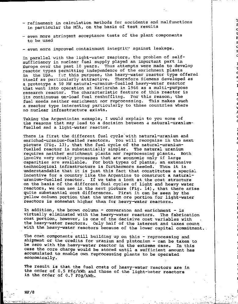
- refinement in calculation methods for accidents and malfunctionsin particular the MCA, on the basis of test results
- even more stringent acceptance tests of the plant componentsto be used
- even more improved containment integrity against leakage.
In parallel v/ith the light-water reactors, the problem of self-sufficiency in nuclear fuel supply played an important part inEurope over the past 10 years. Thus attempts were made to developreactor types permitting independence of the enrichment plantsin the USA. Far this purpose, the heavy-water reactor type offereditself as particularly attractive. Therefore Siemens developed asa prototype a 50 MW natural-uranium-fuelled heavy-water reactorthat went into operation at Karlsruhe in 1966 as a multi-purposeresearch reactor. The characteristic feature of this reactor isits continuous on-load fuel reshuffling. For this reason, thefuel needs neither enrichment nor reprocessing. This makes sucha reactor type interesting particularly to those countries whereno nuclear infrastructure exists.
Taking the Argentinian example, I would explain to you some ofthe reasons that may lead to a decision between a natural-uranium-fuelled and a light-water reactor.
There is first the different fuel cycle with natural-uranium andenriched-uranium-fuelled reactors. You will recognize in the nextpicture (Fig. 13), that the fuel cycle of the natural-uranium-fuelled reactor is substantially simpler. The natural uraniumrequires neither enrichment plants nor reprocessing plants. Bothinvolve very costly processes that are economic only if largecapacities are available. For both types of plants, an extensivetechnological infrastructure is furthermore needed. Thus it isunderstandable that it is just this fact that constitutes a specialincentive for a country like the Argentine to construct a natural-uranium-fuelled reactor. If we take a look at the cost structureon the basis of the different fuel cycles of light and heavy waterreactors, we can see in the next picture (Fig. 14) , that there arisequite substantial cost differences. First it can be seen by theyellow column portion that the uranium ore portion for light-waterreactors is somewhat higher than for heavy-water reactors.
In addition, the brown column - conversion and enrichment - isvirtually eliminated with the heavy-water reactors. The fabricationcost portion, however, is one of the decisive cost variables withthe heavy-water reactors. Only half of the interest and taxes countwith the heavy-water reactors because of the lower capital commitment.
The cost components still building up on this - reprocessing andshipment or the credits for uranium and piutonium - can be taken tobe zero with the heavy-water reactor in the extreme case. In thiscase the core charge would be stored until a sufficient amount hasaccumulated to enable own reprocessing plants to be operatedeconomically.
The result is that the fuel costs of heavy-water reactors are inthe order of 0.5 Pfg/kWh and those of the light-water reactorsin the order of 0.7 Pfg/kWh.
HF/8

nctions
n t s
elf-in
develop.ntsie offeredoped asctorirpose:or isthei suchwhere
i ofiranium-
un and:he nextLum-lium, Both:ge:ensiveLt isi speciallatural-ructurery waterlere arisejy theit-water
- isabricationas withixes countcommitment.
ig andtaken toIn this
aunt hassd
are intors
The importance of the cost influence of reprocessing may be seenfrom the next figure 15 in particular with due allowance for theconditions differing between Europe and countries like the Argen-tine that have not available an analogous nuclear infrastructure.Here are represented the fuel costs for light and heavy-waterreactors as a function of the reprocessing costs. The reprocessingcosts depend on the one hand on the shipping distance from the~reactor to the reprocessing plant, and on the other hand on thecapacity of the reprocessing plant concerned. -~
If we assume the extreme case, as it actually exists in the Argen-tine, that the fuel assemblies for the Atucha nuclear power stationcannot be reprocessed domestically, there results between lightand heavy-water reactors the cost difference shown of 0.2 Pfg/kWh- that is, of approx. 0.6 Pfg/kWh - for D_0 reactors and for thelight-water reactors the cost limit of 0.8 Pfg/kW.
In between, the influence of the shipping distance has been madeclear once more in the oblique curve by assuming that the fuelassemblies are reprocessed in Europe or the United States. Thiswould, for a distance of 10.000 km and with a relatively largeAmerican reprocessing plant, result in costs of approx. 20.- $/kgof uranium for reprocessing, which would correspond to a costdifferential of approximately 1/10 Pfg/kWh.
If for comparison is assumed a high cost portion for reprocessing -that is, if relatively small plants could be made available in therange between 500 and 1000 km - there results yet a cost differentialof 1-2/10 Pfg/kWh.
In other words: With a non-existing infrastructure for the fuelcycle, the fuel costs assume another weight than e.g. in Europeor in the United States, where reprocessing plants in economicunit sizes exist at relatively short distances. For if these2/10 Pfg/kWh are capitalized over the service life of the Atuchanuclear power station, that is, an order of magnitude of 30 years,there results a cost addition of 50 million DM. From this aspect,it is understandable why the natural-uranium reactor has an impor-tance in Latin America different from that in Europe.
The view would be incomplete if the possibilities of furtherlowering of the fuel costs wi£h natural-uranium-fuelled reactorswould not be considered, too. This fael cost reduction is attainableby raising the burn-up, and the burn-up in turn by the so-calledminimum enrichment. The term "minimum enrichment" implies3- *,hat. thenatural uranium is enriched up to the order of 1.2 % of U-235 byinserting the uranium accumulated from light-water reactors afterreprocessing or using available plutonium to increase the degreeof enrichment. From this aspect, the burn-up may be increased fromapprox. 7000. MWd/te to 18,000 MWd/te.
This increase in burn-up would reduce the fuel costs further fromapprox. 0.5 Pfg/kWh to 0.4 Pfg/kWh. This cost saving of JUi wouldin turn amount to 25 million DM over the lifetime of the nuclearpower station.
The conclusion to be drawn is that for the long-term fuel strategythe natural-uranium^fuelled heavy-water reactor still offers bythe use of minimum-enrichment U-! ̂ 35 or plutoriium a flexibilitymaking possible a cost saving of 25-50 million DM over the life-.
HF/9
' .,, v_ .-,'_ _ , __ \ 2. i

time of the nuclear power station.
If a switch is now made from the economic cost calculations tothe. analysis of necessary investments from the aspect of thenational economy and to the resulting foreign-cucrency require-ments for the various reactor types, this afforas an interestinginsight into . the most important influencing factors. In the nextfigure (16) have been plotted the costs and the foreign-currencyrequirements for five 600 MW nuclear power stations, that is fora development programme as it would be provided over a decadefor a country like the Argentine. This has been based on adomestic production of uranium, heavy water and zirconium.
In the case of the light-water reactors, it would have to bsexpected that this capacity of 3000 MW would require a capitalof approximately 1.6 billion DM over a decade. To this wouldstill be added 16 % interest and taxes, that is, about 260 mil-lion DM. For the fuel inventory of enriched uranium, anotherapproximately 400 million DM would have to be expended, so thatthe overall investment cost would be near to 2.3 billion DM.
For a 2 0-year period of operation, another 1.5 billion DM ofcosts would have to be expected for refuelling, maintenanceand personnel, so that taken as a whole over a period of 20 yearsthese five nuclear power stations would cause costs in the orderof 3.8 billion DM in the case of light-water reactors. If these3.3 billion DM are then broken down into the foreign currencyportions necessary, there result for each plant approximately900 million DM and for uranium enrichment over the whole periodincluding conversion at a price of 26.- $/kg another 600 millionDM. The overall requirement in foreign currency would thereforebe approximately 1.5 billion DM with the light-water reactorsor 40 % of the overall cost of these five nuclear power stations.
The analogouefigures in the case of the heavy-water reactorshow that here is added first the heavy-water inventory, onthe assumption that the heavy water is produced domestically atan average unit cost of 200.- DM/kg. The overall investmentcosts lie in the range of 4.2 billion DM, that is, they areabout 350 million DM higher than with the light-water reactors.The foreign-currency requirement, however, amounts to only2/3 of that of the light-water reactors or to 25 % of the over-all cost over a period of 20 years.
The conclusion is that the decision for the natural-uranium-fuelled reactor enabling a major portion of the processing andfinishing work to be performed domestically becomes understand-able also from the ^spect of lower foreign-currency requirements.
The soundness of this reasoning became apparent by the firstgreat export success of the German reactor industry in theArgentine. In the face of fierce competition from the nuclearcountries, it was achieved for the first time in 1968 to obtainan order for a German nuclear power station. This is the 340 MWAtucha nuclear power station based on the natural-uranium-fuelled heavy-water concept of the multi-purpose researchreactor (MZFR), The plant will go into operation in 1972; thepresent situation on site may be seen in Fig. 17. The dominatingfeature is construction of the reactor building; as with the
As
HF/10

other pressurized-water reactors, this is here, too, a sphericalcontainment in which all high-pressure-'containing primary loopsare enclosed. The concreting work for the steel liner has beencompleted. At present the last plate sections of the steellinerare being welded, so that the pressure test can be started inJuly of this year. Of special interest is the large crane. Thisis the largest crane in Latin America enabling unloading of heavylifts, such as the 400 te reactor pressure vessel, to be performeddirectly from ocean-goingships. The crane has a span of 60 m andalso covers the entire reactor-building erection area.
At this juncture I should mention briefly that above all inconnection with the nuclear power station projects in the Argentineand in Holland a large number of employees from these countriesare being employed in our various departments. From a number ofother countries, too, employees of private companies and govern-ment agencies are staying with our company for co-operation ortraining purposes.
This fact is of great importance also with a view to enabling thedomestic industries of the country concerned to perform suppliesand services in connection with the construction of a nuclearpower station, since this way ensures best that the requiredexpertise and special know-how is gained by the domestic industryconcerned. Thus, for instance, we have undertaken to purchase inthe case of Atucha nuclear power station about 30 % of the suppliesin the Argentine, and in the case of the Borssele nuclear powerstation, about 70% of the supplies in Holland.
Reverting now to our representation of reactor types in Fig. 2:It will most strongly depend on the technical development of enrich-ment processes how far the natural-uranium-fuelled heavy-watertype of reactor will succeed in gaining an important share of themarket particularly in the developing countries. As you willcertainly know, the Federal Republic of Germany together withGreat Britain ar.d Holland is engaged in work on the ultra gascentrifuge process. If efforts are successful to develop for thispurpose an enrichment technique economically -jompetitive even forsmall capacities, the potential market of the natural-uranium-fuelled heavy-water reactor will be considerably reduced at leastin Europe. However, at present, nobody is able to formulate aclear answer to this question.
As another heavy-water development must still be mentioned theDpO moderated, C02-cooled pressure-tube reactor of which a 100 MW
prototype is presently under construction at Niederaichbach. Theconsiderations leading then to the decision to build this reactortype started from the facts that high-temperature gas coolingpermits higher efficiencies and that the pressure-tube conceptin comparison with the steel-vessel-enclosed reactor did notresult in a capacity limitation in the range above 600 MW. In themeantime, however, difficulties have arisen with the berylliumcladding material necessary for natural-uranium operation, sothat either a switchover must be made to steel canning, whichleads automatically to an enrichment of natural uranium to 1:15%of U-235, or a .zirconiumcopper alloy must be used. The first coreinventory is steel-clad; in the long term, however, it is envisagedto employ a zirconiumcopper alloy, which unfortuhately reducesf^thepermissible coolant temperature,; thereby reducing the efficiencyadvantage over water reactors. In addition, larger pressure vessels
HF/11

can be constructed today. Therefore, it cannot yet be foreseen today jwhether this reactor type will still have a genuine economic advantage jover the water reactor in the future. i
The picture would not be complete if we disregarded the future develop- jment of fast breeders, where development is primarily concentrated on |the sodium technology. First experience can be gained with the 18 MW !KNK reactor (Fig. 18), to go into operation in 1970; this is pri-marily a thermal reactor, but will receive as second core a so-calledfast core, thus permitting first irradiation experience with fast-breeder type fuel assemblies. The next development step will be theconstruction of a 300 MW fast-breeder prototype (SNR) , for which thedecision to build is expected in 1970. In all probability it will bepossible to start constructing a 600 to 1000 MW demonstration plant in1975. Further development stages are the study of a fuel assembly testbed and the development of carbide fuel assemblies. A scale model ofthe 300 MW prototypeplant is depicted in Fig. 19.
May I summarize my previous statements in saying that after 10 yearsof development we can recognize today a multitude of reactor types,but that only few types have survived this selection process. In thisprocess, the light-water reactors have taken an outstanding lead incomparison with all other types. The future of the natural-uranium-fuelled heavy-water reactors depends most strongly on whether effortswill be successful to produce enriched material economically even forsmall capacities. Accordingly, the heavy-water reactor type willbe an alternative to the light-water reactor primarily in developingcountries.
This leads me to the problem of how the selection process between con-ventional and nuclear power station will develop in the future. Here,too, the interrelated lines of development can be foreseen muchmore clearly than it was still possible not so many years ago.
It would be an illusion to assume that nuclear power stations wouldwholly displace fossil-fired stations in the future. In contrary,there will evolve compounding concept between fossilfired and nuclearpower stations together with pumped-storage, hydro stations. Thisresults simply from the differing cost structure of these powerstation types. Whereas nuclear power stations have high plant costs,but low fuel costs, it is exactly the other way around with fossil-fired power stations, from which fact result differing generating costsas a function of the mode of operation - that is, of the time ofutilization - for the individual power station types.
Fig. 20 shows that from an utilization of 5000 hours upwards nuclearenergy has virtually the lowest generating costs with unit ratings of600 MW and above. Below 5000 hours of utilization, howeverrthe use ofnatural-gas- or oil-fired power stations is more economical. In thiscontext, the great importance of hydro power must be taken into con-sideration, too. It is only in interconnection with the developedhydro resources and those still worthy of development that nuclearenergy has a chance of being used at . its economic optimum. In thisset-up, the combination with pumped-storage hydro plants particularly wellsuited to--peaking plays a special part. Whereas the nuclear powerstations will take over the base load in the future (Fig. 21) , that is,depending on the unit size, and level of fuel costs, the pumped-storageplants can be used especially for peaking in cyclic day/night operation.The. medium-load range will continue to be held by the fossii-firedor hydro power stations. Of course, the existing hydro resourcescannot be ousted^f-rbm the base load.
HF/12 "- » . ;
* —t~-r--~- . - c _-,.

todaydvantage
develop-.rated onLe 18 MW»ri-•called:ast-be theLich therill be>lant inibly testlodel of
yearsrpes,In this
id ininium-jffortsren for
sloping
sen con-2. Here,
ary,luclearrhisecosts,ssil-ing costsof
uclearings ofe use ofIn thiso con-lopedlearIn thiscularly wellpowerthat is,-storageoperation.-firedrces
Another interesting application of nuclear energy results with thechemical industry. The high process steam consumption makes the useof nuclear power stations particularly ..ttractive, for the low fuelcosts permit a low process-steam price. For process steam gene-ration (Fig.22) part of the steam generated in the steam generatorsof the reactor plant-is expanded in, a, backpressure turbo-generatorunit to the required process steam conditions and passed from there tothe loads in the works area. Another portion of the generated steamis used for straight power generation in a condensing turbo-generatorunit. This combination of process steam and power generation enablesa cost breakdown to be obtained which is to the benefit of both pro-ducts. You may recognize this from the cost comparison of Fig. 23,where power and steam costs for a nuclear or oilfired power stationare depicted as a combined product.If, for instance, the power generating cost is assumed to be 2 Pfg/kWh,this results in a steam cost with the nuclear power station of approx.2.70 DM/te, whereas this cost is approximately 7DM/te in the case of anoil-fired station.
Today, the large chemical companies have drawn the conclusions fromthis finding. As already mentioned, BASF intend to construct anuclear power station for power and process steam generation. Similarplans are in hand for a decision at Farbwerke Hoechst, and at Huls andLeverkusen, too, the chemical indust-y is studying intensely theeconomic advantages of nuclear process steam generation.
Another possibility for the application of nuclear energy lies inthe field of potable water production from sea or brackish water.However, to obtain the benefit of the cheap nuclear energy, large dual-purpose plants must be installed in each case, where beside the heatfor potable-water production appreciable amounts of electric powerwill be generated. In Fig. 24 are shown schematically the two dis-tillation processes eligible today for large-scale potable-waterproduction, by means of low-temperature heat. These are the so-calledmulti-stage evaporation (top) or the multi-stage flash distillationprocess (bottom). As may be seen in Fig. 22, the mode of operationof a large dual-purpose plant is in principle the same as above inthe ease of the process steam generation plant. Part of the steamgenerated in the reactor is passed into the sea water desalinationplant after having been expanded to the required working pressure inbackpressure steam turbo-generator units; " The other partial flow isused for power generation in condensing turbo-generator units. Bythis combination, interesting costs for both products - potable waterand electric power - may be obtained. In Fig. 25 are represented thelimiting potable water and electric power costs for 3 different nu-clear power station sizes with a constant size of the potable-waterproduction plant. If 2 Pfg/kWh is used again as the power 3ost figure,there will result potable-water costs between 0.50 - 0.75 DM/m .
The use of nuclear energy for ship propulsion purposes, too, hasnot yet achieved its breakthrough. It is true that there existdemonstration ships having proven their ability to function, yet sofar efforts have been unsuccessful to achieve substantial economicadvantages over conventional types of ship propulsion. In the FederalRepublic of Germany, the reactor of the "Otto Hahn" became critical forthe first time in August, 1968. This is an experimental ship of 11,000SHP, which to date has covered a distance of approx. 50,000 nauticalmiles without incidents. _.The reactor shown in Fig. 26, an advancedpressurized-water reactor (FDR) of Babock/Interatom, has been operatingfor an overall period of 70ti0 hours. -
HF/13;

This leads me to the close of my talk. It was intended to giveyou a picture of the variegated nuclear activities of the asso-ciation of companies working with KWU. It was just during thepast year that in the Federal Republic of Germany nuclear energywas adopted by a great number of electric utilities. You may re-cognize from the last slide how the nuclear power stations underconstruction or in operation are distributed over the Federal Re-public of Germany. The plants in operation are coloured red andthose presently under construction green. This shows that thereis no marked preference for certain regions r but the power stationsare distributed over the various energy supply areas from the northto the south of Germany. The right-hand presentation gives an ideaof the nuclear power stations being planned, which are centredespecially on the Rhine with the power-intensive chemical industry.
Accordingly it may be stated that nuclear energy has reached thecommercial phase in the Federal Republic of Germany, and that con-struction and operating experience is accumulating on a broadbasis.
(1)
(2)
(3)
(4)
(5)
(6)
(7)
(8)
(9)
(17)
(18)
(19)
(20)
(21)
(22)
(23)
(24)
(25)
(26)
(27)
(ID :(12) i
(13) ](14) (
(15) 3
(16) (
HF/14

iveo-ergyre-derRe-anderetationsnorthn ideadustry.
thecon-ad
(1)(2)
(3)
(4)
(5)
(6)
(7)
(8)
(9)
(H
(11)
(12)
(13)
(14)
(15)
(16)
(17)
(18)
(19)
(20)
(21)
(22)
(23)
(24)
(25)
(26)
(27)
List of Illustration
Co-operation of reactor design groups with Kraftwerk Union
KWU's reactor types
Mode of operation of the Wiirgassen nuclear power station
Nuclear steam supply system with containment structure
670 MW Wiirgassen nuclear power station Stage of constructionin July, 1969.
Conceptual perspective view of the Brunsbuttelkoog plant
Availabilities of the Lingen and Cbrigheim nuclear power stations
Construction site of the Stade nuclear power station
Mode of operation of the Biblis nuclear power station
Siemens pressurized-water reactor for a 660 MW nuclear power
station.
1200 MW Biblis nuclear power station
1200 MW steam turbine for Biblis nuclear power station
Fuel cycle of H-O reactors and DJD reactors
Comparison of fuel replacement, costs of PWR (H_O)
Fuel costs for H_O and D?0 reactors as a function of reprocess-
ing costs and distance from the reproscessing plant
Costs and foreign-currency requirements for 5x600 MW nuclearpower stations with domestic uranium, D-O, and zirconium pro-duction in million DM
340 MW Atucha nuclear power station
Structure and time schedule of fast breeder development in theFederal Republic of Germany
300 MW SkA fast breeder, scale model
Average generating costs as a function of load factor (withoutreserve, during the seventies)
Permanent weekly load characteristic and load distribution,in 1989.
Arrangement of a nuclear power station installation for totalenery
Steam and power costs for a nuclear and an oil-fired power station
Processes for scawater desalination using low-grade heat
Power and potable water costs for light-water nuclear powerstations
Advanced pressurized water reactor for nuclear energy researchship
Nuclear power stations in the Federal Republic of Germany
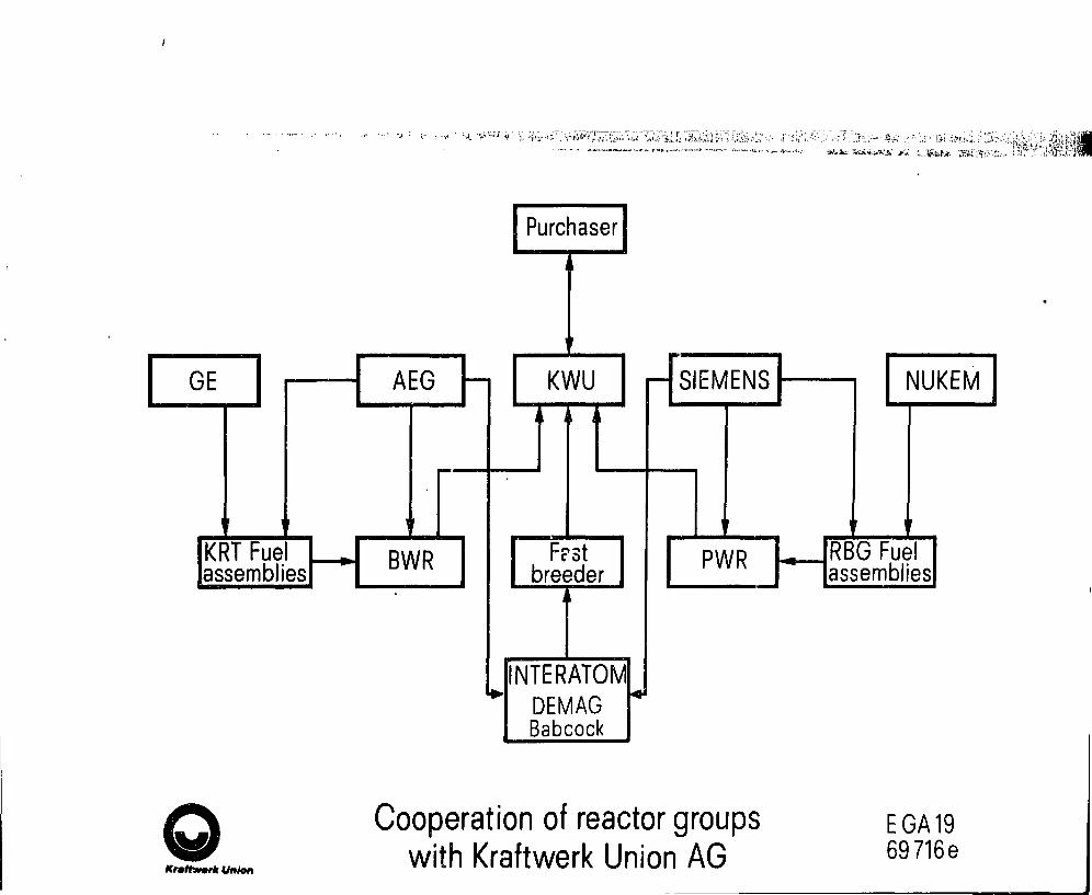
•••• - • - - " - • ; « - > • * ' --A • • f "
GE
KRT Fuelassemblies
AEG
BWR
Purchaser
KWU
F?stbreeder
NTERATOMDEMAGBabcock
SIEMENS
PWR
NUKEM
RBG Fuelassemblies
Krmttmrk Union
Cooperation of reactor groupswith Kraftwerk Union AG
EGA 1969 716e

Kraftwerk Union
Light water Heavy water
CharacteristicModerator, coolant fuel
Power stationsin operationGross output
Designation
Commissioning year
Power stationsunder constructionGross outputDesignationCommission:^] vear
boiling H2O
2.5/ U235
16 MW
Kahl
1961
250 MW
Gundremmmgen
1966
250 MW.Lingen
1968
670 MWWurgassen
1972
810 MW
Brunsbuttel
1975
900 MWEichau
1975
^ ^
r~ —«H 2 0 steam 13 A U235
I25 MW jnuclear superheat
[reactor 1969
2x480MW+2x1000 t/hBASF1975
^ \
pressurized H2O3> U235
300 MW
Obrigheim
1968
660 MWStade1972
450 MW
Borssele
1973
1200 MWBiblis
1974
Pressurized D2O
Unat
57MWMZFR1966
340 MWAtucha1972
I D2O/COZ
! 1.15- U235
fiOOMW ~Niederaichbach
Reactor types offered by Kraftwerk UnionUlS

Kraftwerk Union
2
-HHBI
1 Reactor2 External recirculation pump3 High-pressure turbine cylinder4 Intermediate-pressure turbine cylinder
5 Low-pressureturbine element
6 Generator7 Condensers
8 Weser river water9 Condensate pump10 Feed-heating plant11 Feedwater pump
Wiirgassen Nuclear Power StationMode of operation
ro

Kraftw&rk Union
SattdampfWasser

Conceptual perspectiTe view of the Brunetiittelkoog plant

Kraftwerk Union
1':1100
80
60
40
20
mum II!
10 11 121968
1 2 3 4 5 6 7 8 9 10 11 121969
100
80
60
40
20
10 11 121968
1 2 3 4 5 6 7 8 9 10 11121969
V=
Lingen nucl.pwr. station
A(MWh)-100To(h>PNet(MWe)
1 21970
V=
Obrigheim nucl.pwr. station
A(MWh)100To(h)-PN.f (MWe)'
2970
1969
the output of the power stationwas increased by about 10
Availability of the Lingen and Obrigheim nuclear power stations 0)5
F


A *
JtLLi

§
i i I
1 1 I

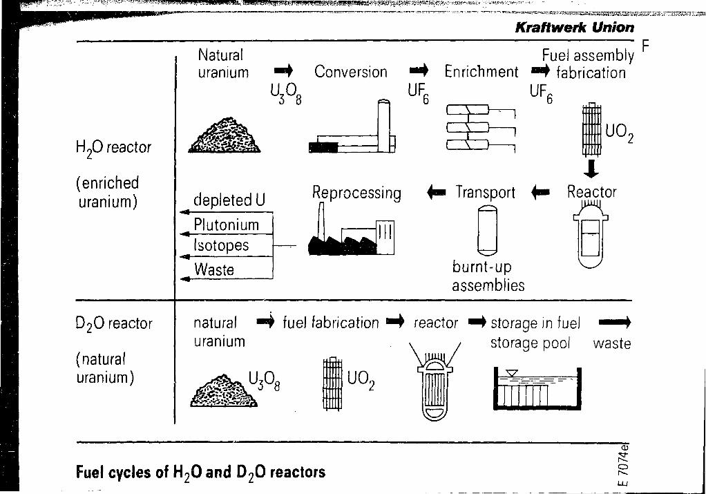
!̂ ^
H20 reactor
(enricheduranium)
D2O reactor
(naturaluranium)
Naturaluranium
Kraftwerk UnionF
ConversionU3°8
Fuel assemblyEnrichment • • fabrication
UR, UF,I V
( \ UO,
depleted U Reprocessing 4 - Transport
PlutoniumIsotopes
Waste
xReactor
burnt-upassemblies
natural " 4 fuel fabricationuranium
reactor
ua
storage in fuelstorage pool waste
Fuel cycles of H20 and D20 reactors
CD
O
r

Kraftwerk UnionF
Rate of interest: 8/o p.a. Operating period: 7000 rva
Dpf/kWhQ g
Fuel costs
0.7
0.6
320 MW reactor without reprocessing
million DMr6
-5
5000-10000 500-1000km distance
short^ 5 0 0 - 1 0 0 0
short longUS$/kgU20 20 60 WA- costs
low low high320 MW D2O reactor without
4
-3
-2
Difference in fuel costs.
Time: 25years
(according
to the present
worth method)
reprocessing0
10 20 50 40 50 60 70 80 90 100 US$/kgU•Costs of transport and reprocessing
Fuel costs for H2O and D2O reactors as a function of reprocessing costsand distance from the reprocessing plant (RP)
CDCD
or--

Kraftwerk UnionF
Argentina
Plant costs and owner s additional expenditureinterest and taxes during construction (16%)
D2O inventory (0.7 te/MW,200 DM/kg)
Fuel inventory (7 $/lb of U3O8)
Investment costs
Operating costs over 20 years (present worth)
(Fuel,personnel, maintenance, D2O losses etc.)
Overall cost over 20 years
of which foreign currency for: plant,
uranium enrichment incl. conversion (USAEC price 26$/kg)
Total foreign-currency requirements for above items
Proportion of overall costs
H2O-reactor
1.625'260'
390'
2.275'1.555'
3.830'
900'610'
1.510'40%
D2O- reactor
1850'295'
460'
110'
2.715'1.465'
4.180'
1.025'
1.025'25%
Costs and foreign-currency requirementsfor 5x600 MW nuclear power stations
CD
O(

k
1:'

Kraftwerk Union
Base program
KNK II20 MW
Prototype reactor300MW
Demonstration plant600/1000 MW
Fuel assemblytest bed study
Carbide fuelassemblies
Initial phasePreliminary investigations
O
Basicinvestigations
first core
Advanced
projecting work construction
I-—O
1960
studies
operation
development construction
O
second core
Toperation
F
O
development
O
construction
operation
fobjective
development construction operation
Odevelopment
• Oirradiation
1965 1970 1975 1980
Structural and time schedule of fast-breeder
devefopment in the Federal Republic of Germany
tO

f^ig^3jg^^ ..... ........
Kraftwerk Union
Pf/KWhao
generating cost 4000 h/a 6500 h/a
domestic bituminous coalimported bituminous coalfuel oilnatural gas
nuclear power
2000 4000 6000 8000 h/a• load factor
Average generating costs as a function of the load factor(without reservejn the seventies)
CM
• • • o i

Kraftwerk Union
MW7000H6500
• 60001 pumped storagehydro power station
pumped storagehydro power station
system load
1. nuclear power station(300MW)
2. nuclear power station (600MW)
3. nuclear power station (600MW)
. nuclear power station (600MW)
5. nuclear power station (1200MW)
12 2*f 36 US 60 72 84 96 108 120 132 144 156 168 ht -
continuous weekly load characteristic and load distribution in 1989Ul

Kraftwerk UnionCondensing turbo-generator unit Backpressure turbo-generator unit
Sea-water evaporation plant(process steam user)
Q
L-fi
Arrangement of a nuclear power station installationfor a total-energy scheme
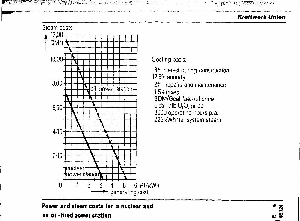
* > ; " - . ' ' • ! ' •
Kraftwerk Union
Steam costs12,00DM/t
10,00^
\ lo i l power station -
2.00
-nuclearpower station^
i i t i i
0 1 2 3
Costing basis:
8% interest during construction12.5% annuity2% repairs and maintenance1.5% taxes8DM/Gcal fuel-oil price6.55 /lbU3O8 price8000 operating hours p. a.225kWh/te system steam
4 5 6 Pf/kWhgenerating cost
Power and steam costs for a nuclear and
an oil-fired power station ui S

7 ; -.'V:.
KranwerK unionMultiple-effect distillation
Sea-water inlet
feed heater
Multi-stage flash evaporation
heat exchanger
evaporator
condenser
1 brinefresh water
condensers
flash chambers
sea-water inlet
I fresh water
brine
Sea-water desalination process using low-grade heat

Kraftwerk Union^
DM/m3
1.50
1.00
0.50
•** IIIvariaiii m
Variai
V vlvariar
\ \
\
It II
It 1
V920 920
Main data of the variants
Thermal reactor output MWth 1.370 2.000 2.690Overall steam flow te h 2.610 3.810 5.130Net overall output MWel 310 510 740Fresh-water flow m'5 d 250.000 250000 250000Heating-steam atm abs 3 3 3pressureHeating-steam flow te h 920
Costing basis8 •' p a interest during construction
10.2 ' p a annuity1.5' p.a. repairs and maintenance
7500 ha fresh-water and backpressure generatedpower production
6000h/a condensing turbo-generatorpower generation
1.0 2.0 3.0 4.0 5.0 Dpf/KWh
Power and fresh-water costs for light-water nuclear power stationsor-.

KraHwerk Union
Under construction or in operation: In the planning stage:
OttoHahni l
*
In operatinUnder constructionPlannedConstruction orders
Electrical output in MW
SalzgitterVeltheimftk300 A1300
600*1 M600arl-Hiils Schmehausen
600^1 Leverkusen•1300Weisweiler
•1900Frankfurt-Hochst
1200A4Ludwigshafen600*iBruchsal
Alomforum
Nuclear power station in the Federal Republic of Germany CO
CTJ