servicing &technology april 1985/$2
TRANSCRIPT
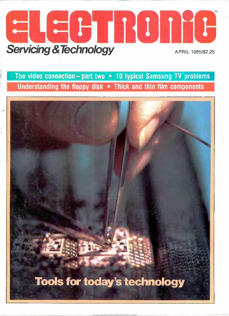
Servicing &Technology APRIL 1985/$2.25
The video connection - part two 10 typical Samsung TV problems
Understanding the floppy disk Thick and thin film components
www.americanradiohistory.com
.N-1 I:ar,
.usiTl<I_
r;
AL
PU1.1
GUM)
CH -2 INV
8 -Trace Capability Alternate Triggering 2 Time Bases
3 -Channel Input
Manufacturer's Suggested List Price
L3O-516 OSC11 OSCOPE tOcao Hz
r\,- T\AAAJ i I 1 t` 1
ILIUM ROTATION
i Vó ONPOWER
--°..11.
Clear, Bright Trace 800,645-5104
H 1 OUTPUT
LwCAL
BITEN LB TIME/DIV AND
BY B A DELAY TIME
ALT
ms
TRIG D
8 TV -H IAalTV.VI
EEP MOD-
AUT(1
AC
DC
TV -V
TV -H
A VARIABLE -- TRAG PULL .10 MAO SEP
PU.I mew' HOLD ` LAVE!. OFF 01
A MG . ,.., . . "Ace
ie 0+5 mV Sensitivity 2 -Year Warranty Coast -to -Coast Service
For immediate delivery or more information call toll -free
In New York State
516-231-6900 Forprofessionals
who know
the difference.
380 Oser Ave., Hauppauge, NY 11788
LEADER Instruments Corporation
For Information Circle (1) on Reply Card For Demonstraticn Circle (2) on Reply Card
www.americanradiohistory.com

Pass up this ad if you don't want to save money
Now call toll free anywhere in Canada Alaska, Hawaii, and Puerto Rico!
ù?t: Yo ., i .,.7 Cur
Complete Electronic El W works p'' sorel
cl around the the loto
bring prices
ro all year urd.
.Hh Your completel^'rcl semiconductor
actor sourcel
i-8004431568 ,gpp 5 u 43-35 TM.
w.a 1-800-762-3472 N.TV
+. ima. ,p, :dfeeWel" n,,.
IMMEDIATE DELIVERY
OPEN EVENINGS AND SATURDAYS
High quality, name brand semiconductors, plus all of the other electronic parts you'll ever need, all under one roof. Give CEI a call today, toll free, and discover why Consolidated Elect- ronics truly is your complete electronic parts sourcel
1-800-543-35G8 7-800-762-3472 NATIONAL WATS OHIO WATS
TELEX NO. 288-229 IN DAYTON:(513) 252-5662
THE CEI PRICE V Check it out!
CEI Consolidated Electronics. Incorporated Your Complete Electronic Parts Source!
705 VVATERVLIET AVE, DAYTON OHIO. 45420-2599 Circle (6) on Reply Card
www.americanradiohistory.com
The how-to magazine of electronics...
GIGOTRONiO s Volume 5, No. 4 April 1985
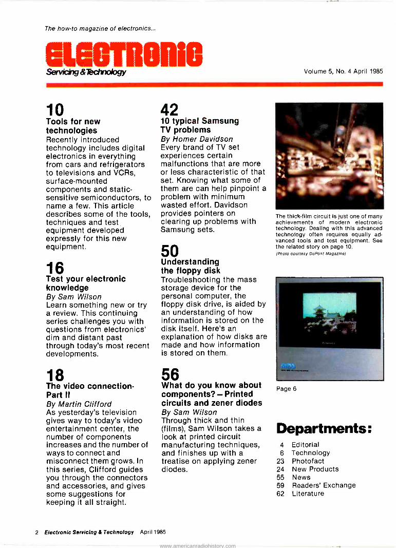
10 Tools for new technologies Recently introduced technology includes digital electronics in everything from cars and refrigerators to televisions and VCRs, surface -mounted components and static - sensitive semiconductors, to name a few. This article describes some of the tools, techniques and test equipment developed expressly for this new equipment.
16 Test your electronic knowledge By Sam Wilson Learn something new or try a review. This continuing series challenges you with questions from electronics' dim and distant past through today's most recent developments.
18 The video connection - Part ii By Martin Clifford As yesterday's television gives way to today's video entertainment center, the number of components increases and the number of ways to connect and misconnect them grows. In this series, Clifford guides you through the connectors and accessories, and gives some suggestions for keeping it all straight.
42 10 typical Samsung TV problems By Homer Davidson Every brand of TV set experiences certain malfunctions that are more or less characteristic of that set. Knowing what some of them are can help pinpoint a problem with minimum wasted effort. Davidson provides pointers on clearing up problems with Samsung sets.
50 Understanding the floppy disk Troubleshooting the mass storage device for the personal computer, the floppy disk drive, is aided by an understanding of how information is stored on the disk itself. Here's an explanation of how disks are made and how information is stored on them.
56 What do you know about components? - Printed circuits and zener diodes By Sam Wilson Through thick and thin (films), Sam Wilson takes a look at printed circuit manufacturing techniques, and finishes up with a treatise on applying zener diodes.
The thick -film circuit is just one of many achievements of modern electronic technology. Dealing with this advanced technology often requires equally ad- vanced tools and test equipment. See the related story on page 10. (Photo courtesy DuPont Magazine)
,.. .,
Page 6
Departments: 4 Editorial 6 Technology
23 Photofact 24 New Products 55 News 59 Readers' Exchange 62 Literature
2 Electronic Servicing & Technology April 1985
www.americanradiohistory.com

The technology is advanced. The
temperature stays put. 5rr
E
g
EC 1000 Dial controlled with EC1201P iron.
WTR,ppllKa
EC 2000 Three digit LED readout with EC1201P iron.
.110.111.7
O,m1R M* [0,b, *O DI000
EC3000 Dial controlled with lightweight EC1301 soldering pencil.
EC 4000 Three digit LED readout with light- weight EC1301 soldering pencil.
All EC Series stations meet Mil -spec DOD - STD -2000-1
When you need controlled output soldering for sensitive components, you don't need uncontrolled temperature fluctuations at the work station. In the Weller EC Series, the tip temperature is maintained throughout the range of 350°F -850°F to within 10°E In addition, an electronic system utilizes thyristor power control with zero voltage thyristor drive. This
ensures that no high voltage spikes or magnetic fields will be present on the soldering tip. These technologically advanced stations are capable of handling all the delicate
soldering operations necessary, in even the most sophisticated applications. They offer the ultimate in soldering flexibility with a choice of controls and readouts to suit your needs precisely.
Weller® EC series Check with your Electronics Distributor.
Coo erTools) The difference between work and workmanship.
BOKER®CRESCENT®LUFKIN®NICHOLSON®PLUMB° WELLERC WISS®XCELITE® The Cooper Group PO Box 728 Apex NC, 27502 USA Tel (919) 362-7510 Telex 579497
Circle (7) on Reply Card
www.americanradiohistory.com
Editorial Wv
Computer as test equipment Since their introduction sometime in the early
seventies, personal computers have evolved from systems that were, for the most part, little more than toys or hobby equipment into real computers that can be used in the home or place of business to store and retrieve information, to process words, to solve mathematical problems or to perform a host of other tasks; not to mention playing games.
This evolution, or perhaps revolution, has been fueled by a number of advancements that occurred more or less simultaneously: The hardware became more sophisticated and easy to use, while the soft- ware also became more sophisticated and easy to use. Because of the avalanche of interest of people in computers, they began to be produced in quantity, and so the price came down. No doubt there are many other reasons that could be cited. As more and more applications of personal computers were developed, it became more and more obvious that the computer is indeed a general purpose device.
One development that has become evident recent- ly, and that should be of great interest to just about anyone who is involved in electronics, is the use of the personal computer as test equipment.
One such example is the oscilloscope peripheral mentioned in this issue in the article "Tools and test equipment for new technology." This unit consists of hardware that picks up the signal to be analyzed and converts the analog signal into a digital signal. The software allows the computer to process the signal information and display it on the face on the com- puter monitor. Because one of the computer's in- herent features is memory, this information about
the waveform may not only be captured and dis- played, but it may be stored for analysis later.
Another computer peripheral that turns the com- puter into a piece of test equipment is the Video Tune -Up for the Commodore 64. In the same article, you'll also find a description of this unit, which con- verts the computer into a full -function video analyzer.
Everywhere you look there are products that con- tain microprocessors. In some cases, the microproc- essor merely adds convenience features; as in a microwave oven where it allows you to thaw the food, then automatically switches into a cooking mode. In other cases, the microprocessors improve energy efficiency, or provide a degree of control not possible by the mechanical systems they're incor- porated into; as in automotive engines. In still other cases, some products we take for granted today wouldn't exist at all, or at least not in the form we're familiar with, were it not for the microprocessor: the videocassette recorder and the digital compact disc player to name two. Now these new peripher- als, in turn, add extra features to an already useful piece of equipment, the personal computer.
It's anybody's guess where microcomputers will show up next, or what new use will be found for the personal computer. There's no question though that the microcomputer will continue to grow in impor- tance, and will have to be well understood by anyone who wants to remain in the forefront of electronics.
cruz. enwgi em_%41_er,
aerewc Editorial, advertising and circulation cor- respondence should be addressed to: P.O. Box 12901, Overland Park, KS 88212-9981 (a suburb of Kansas City, MO); (913)888-4664.
EDITORIAL Nils Conrad Persson, Editor Carl Babcoke, Consumer Servicing Consultant Rhonda Wickham, Managing Editor Joy Culver, Associate Editor
ART Kevin Callahan, Art Director Joni Harding, Graphic Designer
CIRCULATION John C. Arnst, Director Evelyn Rogers, Manager Dee Manies, Reader Correspondent
ADMINISTRATION R. J. Hancock, President Cameron Bishop, Publisher Eric Jacobson, Associate Publisher
ADVERTISING Greg Garrison, National Sales Manager Julie Roberts, Production Manager Stephanie Fagan, Marketing Coordinator Kelly Hawthorne, Marketing Assistant
MP
Member, Audit Bureau of Circulation
Member, American Business Press
ELECTRONIC SERVICING & TECHNOLOGY (USPS 462-050) (with which is combined Electronic Technician/Dealef) is published monthly by Intertec Publishing Corp., 9221 guivira Road, P.O. Box 12901, Overland Park, KS 66212-9981. Second Class Postage paid at Shawnee Mis- sion, KS 66201. Send Form 3579 to P.O. Box 12952, Overland Park, KS 66212.9981.
ELECTRONIC SERVICING & TECHNOLOGY Is the "how-to" magazine of electronics. It is edited for electronic profes- sionals and enthusiasts who are Interested in buying, building, Installing and repairing home -entertainment elec- tronic equipment (audio, video, microcomputers, electronic games, etc.).
SUBSCRIPTION PRICES: one year $18, two years $30, three years $38 in the USA and its possessions. Foreign countries: one year $22, two years $34, three years $44. Single copy price $2.25; back copies $3.00. Adjustment necessitated by subscription termination to single copy rate. Allow 6 to 8 weeks delivery for change of address. Allow 6 to 8 weeks for new subscriptions.
PHOTOCOPY RIGHTS: Permission to photocopy for internal or personal use is granted by Intertec Publishing Corp. for libraries and others registered with Copyright Clearance Center (CCC), provided the base fee of $2 per copy of arti- cle Is paid directly to CCC, 21 Congress St., Salem, MA
01970. Special requests should be addressed to Cameron
Bishop, publisher. ISSN 0278-9922 $2.00 + 0.00
INTERTEC PUBLISHING CORPORATION
°1985 All rights reserved
4 Electronic Servicing & Technology April 1985
www.americanradiohistory.com

Take home a world
champion. 85*
gets you a technical knockout.
The Fluke 70 Series. Winners of the digital vs. analog battle. Since their debut, they've become
the worldwide champions of the industry.
Never before have such tough, American -
made meters offered so many professional
features at such unbeatable prices.
Each comes with a 3 -year warranty, 2,000+ hour battery life, and instant autoranging.
You also get the extra resolution of a 3200 -
count LCD display, plus a responsive analog
bar graph for quick visual checks of continuity,
peaking, nulling and trends.
Choose from the Fluke 73, the ultimate in
simplicity. The feature -packed Fluke 75. Or the
deluxe Fluke 77, with its own protective holster
and unique "Touch Hold" function** that
captures and holds readings, then beeps to
alert you.
So don't settle for just a contender. Take
home a world champion. For your nearest distributor or a free
brochure, call toll -free anytime
1-800-227-3800, Ext. 229. From outside the
U.S., call 1-402-496-1350, Ext. 229.
FROM THE WORLD LEADER IN DIGITAL MULTIMETERS.
FLUKE 73 FLUKE 75 FLUKE 77 $85' $99' $129"
Analog/digital display Analog/digital display Analog/digital display
Volts, ohms, IOA, diode Volts, ohms, 10A, mA. Volts, ohms, 10A, mA
test diode test diode test
Autorange Audible continuity Audible continuity
0.7% basic dc accuracy Autorange/range hold "Touch Hold" function
2000+ hour battery life 0.5% basic dc accuracy Autorange/range hold
3 -year warranty 2100+ hour battery life 03% basic dc accuracy
3 -year warranty 2000+ hour battery life
3 -year warranty
Multipurpose holster
Suggested U S. list price, effective July 1,1984. ' Patent pending.
FLUKE Copyright © 1984, John Fluke Mfg. Co., Inc. All rights reverved. Ad No. 4701-70 For technical data circle number 8 o
www.americanradiohistory.com
Flat color television is on the way
A newly developed color display may soon replace standard CRTs with flat screens in TV/video equipment. The flat panel, de- veloped by Matsushita Electric In- dustrial Company, has been incor- porated in a prototype of a flat col- or television featuring a 10 -inch diagonal screen and a depth of less than four inches.
The color flat panel features a square, completely flat screen which reproduces distortion -free images throughout the entire dis- play area. These features make the screen suitable for new media and office automation display applica- tions where space efficiency is crucial. New media consist of several new services, including teletext, direct broadcast satellite, high definition TV and cable/pay TV.
The color flat panel was de- veloped using Matsushita's matrix drive and deflection system. The panel's screen consists of 3000 pic- ture cells arranged in a matrix: 200 units horizontally and 15 ver- tically. Each picture cell is scanned by one electron beam which ex- cites phosphor stripes.
The matrix drive and deflection system produces a color flat panel that has the flatness of LCD (liquid crystal displays) and EL (electro - luminescent) displays, as well as the high color reproducibility, high resolution and brightness of ex- isting color picture tubes.
Matsushita's flat color TV pro- totype provides a resolution of 270 TV lines, a contrast ratio of more than 50, and a brightness of more than 70 -foot -Lamberts (fL).
Matrix drive and deflection system
The matrix drive and deflection system produces 3000 controlled beams by forming a matrix of 15 filament cathodes and 200 elec- tron -beam control electrodes which cross cathodes at right angles.
Each beam is horizontally deflected in six steps (two sets of RGB) and vertically deflected in 32 steps (including the interlace) to form images consisting of 192,000 elements on the display panel. A complete picture is formed through the line -at -a -time method.
This deflection method also reduces the number of electrode terminals required to approx- imately 1/7 of the number used in the conventional matrix driving method.
MATRIX DRIVE AND DEFLECTION SYSTEM
Rear wall
Filament cathode
Electron beam
Phosphor stripe
Face plate
Vertical deflection electrode
Electron beam control electrode
Horizontal deflection electrode
Unit screen
Screen size: Dimensions:
Weight: Power consumption: Brightness: Resolution:
Contrast:
SPECIFICATIONS
Color Flat Panel
200mm x 150mm 282(W) x 222(H)
x 65(D)mm 7.5kg 7W 70f L
picture element pitch of 0.5mm More than 50
Flat Color Television
10 -inch diagonal 370(W) x 355(H)
x 99(D)mm 14kg 70W 70f L
270 TV lines
Gray scale: 64
6 Electronic Servicing & Technology April 1985
www.americanradiohistory.com
Sams makes it simple! ES &T makes it economical!
ES & T Book Club offers a 20% discount on these Sams books:
To Mai
ArdServe Srtm1 ÇMe'
SEMICONDUCTOR GENERAL PURPOSE REPLACEMENTS (5th Edition) includes almost 225,000 bipolar and field-effect transistors, diodes, rectifiers, ICs and more. No. 22418, List price $9.95, Your price $7.95.
VIDEO CAMERAS: THEORY AND SERVICING introduces you to all aspects of video cameras from image tubes to the final interface. Includes a helpful troubleshooting section. No. 22382, List price $14.95, Your price $11.95.
HOW TO MAINTAIN AND SERVICE YOUR SMALL COMPUTER provides simple maintenance procedures you can use on all small computers to reduce problems and downtime. No. 22016, List price $17.95, Your price $14.35.
MICROPROCESSOR BASED ROBOTICS teaches you the mechanics of robotic arms and legs, tactile sensing, motion and attitude sensing, vision systems and voice command systems. No. 22050, List price $16.95, Your price $13.55.
PNEUMAETNICTS INSTRUM
EucTRONIC f5 INS
The .r
IIMN¡w
HOWARD W. SAMS CRASH COURSE IN DIGITAL TECHNOLOGY quickly provides you with a solid foundation in digital fundamentals, state-of-the-art components, circuits and techniques. No. 21845, List price $19.95, Your price $15.95.
INSTRUMENTATION TRAINING COURSE- PNEUMATIC AND ELECTRONIC INSTRUMENTS (Vol. 1
and 2) is a two -book set that presents theory, construction, alignment, installation and operation of a variety of pneumatic and electronic instruments. No.21581, List price $27.95, Your price $22.35.
INTRODUCTION TO THE ANALYSIS AND PROCESSING OF SIGNALS (2nd Edition) covers periodic, aperio- dic, sampled -data, random signals, signal comparisons, filters, signal recovery and more. No. 22253, List price $19.95, Your price $15.95.
UNDERSTANDING DIGITAL LOGIC CIRCUITS is written for radio, TV or audio techni- cians interested in digital logic. It covers adders and subtractors, flip- flops, registers, encoders and decoders. No. 21867, List price $18.95, Your price $15.15.
ANALOG ELECTRONICS AND MICRO- COMPUTER SYSTEMS covers power supply design, analog signal conditioning, data acquisition principles, data communication links, implementation of PID
control and more. No. 21821, List price $19.95, Your price $15.95.
ANALOG INSTRUMENTATION FUNDAMENTALS provides excellent coverage of ammeters, voltmeters, ohmmeters, bridges, filters and attenuators. Includes many hands-on examples. No. 21835, List price $19.95, Your price $15.95.
DESIGN OF OP -AMP CIRCUITS WITH EXPERIMENTS illustrates the design and operation of linear amplifiers, differentiators and convertors voltage and current converters, and active filters. No. 21537, List price $11.95, Your price $9.55.
ELECTRONIC PROTOTYPE CONSTRUCTION discusses IC -based and microcomputer -related schematics and ideas for evaluation and testing. No. 21895, List price $17.95, Your price $14.35.
r Order as many Sams books as you want!
QUANTITY BOOK NO. PRICE AMOUNT
Amount of Order $
GIECTRORiC Add Shipping & Handling 2.00
Servici,y.Tech y Total Amount of Order $
- PAYMENT ENCLOSED - MONEY ORDER - MASTERCARD Interbank No
Account No Expiration Date
Name (print)
Signature
Address
City State Zip
Mail to: Electronic Servicing and Technology Book Club P.O. Box 12901 Overland Park, KS 66212
CHECK
VISA
L Circle (9) on Reply Card
d
April 1985 Electronic Servicing & Technology 7
www.americanradiohistory.com

Focusing technology of electron beam
This system's lack of a shadow mask, found in conventional color picture tubes, necessitates a fine electron beam of the same width as a phosphor stripe. Matsushita found the optimum electrode structure using the 3 -dimensional simulation technology previously developed by the company.
Separation of the horizontal and vertical lens systems to provide in- dividual control of their focusings resulted in improved resolution and color reproducibility.
Precision processing and assembly technology
Uniform electronic character-
istics, to assure uniformity in brightness and purity in color, were provided by the development of a processing technology for precision structural components and a relevant technology for precision assembly of these com- ponents. Of special importance to uniform display was the develop- ment of a cementing process that evenly and alternately adheres 0.1mm grid electrodes with in- sulating plates.
Digital technology Signal processing and driving
are performed digitally. Picture brightness is controlled by varying the pulse width that drives elec- tron beams, thereby generating 64
steps in gray scale. Color reproduction is performed
by digitizing the picture signal and alternately driving red, green and blue signals. Resolution is marked- ly improved by giving time differ- ences in sampling each.
Using a microcomputer for fine adjustment of the diameter and position of electron beams on the phosphor screen results in uniform brightness and high color repro- ducibility.
Through the development of these new technologies, the flat color television is said by the manufacturer to offer crisp, high - quality pictures that cannot be pro- duced by conventional flat color displays.
Register temperature in one minute Digital thermometer
SPECIFICATIONS
Range 32.0-43.0°C
90.0-110.0°F
Accuracy ±0.1 °C
± 0.2°F
Display 3 -digit LCD
Response Time Oral -1 min. Armpit -2 min.
Peak Hold Device Incorporated
Indicator 4mm-high LCD
Switching Push-button
Battery Silver oxide (SR -41W type)
Power Consumption 0.3mW; up to 2050 measurements
Automatic Power -Off After 10 min.
Dimensions 120 x 12.9 x 10.5mm (47 x 5.0 x 4.1 inch)
Weight 9g (3 ounces)
An electronic clinical ther- mometer that features a read -at -a - glance 3 -digit LCD has been de- veloped by Toshiba Glass Com- pany, a subsidiary of Toshiba Cor- poration. This electronic unit is as precise as a glass tube mercury thermometer - accurate within 0.2°F (0.1°C)-yet takes only one minute under the tongue to reg- ister the body's temperature.
Other features of the ther- mometer include: a wide measure- ment range - 90° to 100°F (32° to 43°C); a visible display that makes it possible to see rather than to read the temperature; and an on/off switch making it un- necessary to shake down mercury after each reading as in conven- tional thermometers.
For this device, a low power con- sumption CMOS LSI chip was developed. This chip calculates temperatures by measuring the small variations in electric fre- quency, as emitted from a heat sensor or thermistor, to match changes in temperature.
The thermometer is offered in either Fahrenheit or Celsius readings and includes a slip-on, plastic protective case. It is available in the United States for about $14. OW,
3 Electronic Servicing & Technology April 1985
www.americanradiohistory.com

ATTENTION TV TECHNICIANS Diehl Engineering, the same people who conceived, designed and now manufacture Super Tech diagnostic computers for analyzing start up, shut down, flyback and flyback related circuits, now has something else that will make your job faster, easier and much more profitable.
A NEW PUBLICATION
You might say that our monthly Technician / Shopowner newsletter is an all out training program for those who are already working in the TV service industry, as well as for those who soon plan to be doing so.
Each month we take at least one concept, circuit or function and totally disect it. We then explain every conceivable aspect in plain and simple English. When we are finished, you not only understand the operation, you also understand how the operation, "inter -reacts" with all of the other circuits that it is related to.
Once every aspect of operation has been explained, we show you how to break the subject down into sections. Then, show you how to troubleshoot each section on an individual basis.
Because of the manner in which our pulication is written, the subject knowledge that is gained in each monthly issue is so broad, that it "spills over" into your every day troubleshooting routine.
Our Technician/Shop owner monthly newsletter is 100% devoted to the TV technician. It contains nothing but pertinant information on TV repair. We do not sell advertising space. Those who subscribe, do so because of its technical content, which we pledge to be far superior to anything else that you can obtain.
Each monthly issue (manual) contains up to 68 pages filled with schematics, diagrams and illustrations that relate to the very circuits that you are seeing today. We do not teach this year's chassis, we realize that you are seeing sets that are five, ten or even fifteen years old.
Our newsletter is not a collection of part numbers that cause specific problems in specific chassis when they fail. Instead, we explain what each indivival component in a given circuit does, what purpose it serves, and what effect it will have if and when it fails.
Our subscribers can look at any resistor, any capacitor, any diode, any transformer, etc., in any circuit, and know exactly what purpose it serves. They will know what turns the circuit on, what turns it off, why and when such action occurs, and what happens if a specific action does not occur.
Our subscribers will no longer have to be content to know that R421 causes a particular chassis to shut down if it becomes open, they will know why it does.
Our subscribers will no longer run around in circles hoping to stumble over a "bad" component, they will know exactly what they are looking for, and - - - how to find it!
When it comes to troubleshooting color TV sets, we have introduced more, innovative techniques than any other firm in the world (including manufacturers).
In case that amuses you, consider this: Everyone else in the industry is telling you to probe here and there in this chassis, there and somewhere else in another chassis, in hopes of isolating the actual circuit that has failed. Conventionally, one specific technique that works for one chassis may do nothing but smoke com- ponents in the next.
Yet, while others have been teaching "conventional" techniques (usually a different one for each chassis), we at Diehl Engineering
designed a computer that will isolate the defective stage in any hi - voltage circuit that employs a horiz output transistor (including Sony). With our Super Tech computer, you push the same four buttons no matter which set you are working on. Any brand, any age any chassis, Super Tech will give you an accurate answer. (see our ad on pg. 13)
We are not implying that those who teach "conventional" techniques are technically incompetant. Far from it, some of them are brilliant! We simply have a new and much easier way of looking at things. Ours is easier to understand and far more versatile. Because of the manner in which we present it, the retention level is also higher (according to those who are now using our literature).
Any staff that can design a computer that can analyze any hi -voltage circuit (except for those which use a trace and retrace SCR i.e. RCA CTC 40-81) must surely have a thorough knowledge of all circuits. Soon we will release similiar computers for vertical and audio circuits, another for tuner, IF, AGC, video, blanking, ABL, Chroma, matrix and CRT, and still another for troubleshooting VCR!
The point is, we at Diehl engineering understand circuitry. We also know how to explian circuitry in such a way that it is easily understood.
Each month's issue is printed in the form of a manual. Each manual is pre -drilled so that it can be filed in a 3 ring binder for instant reference (the 3 ring binder is not provided).
The First Issue covers resistors, capacitors, diodes, inductors, tran- sistors, IC chips and time constant circuitry. It explains how each com- ponent works, why it works, why it fails, and how each component relates to the overall circuit, all in plain and simple, down to earth, everyday English, without the use of mathmatical formulas. After reading this issue, you can look at any component in any circuit and truly understand what it does, why it does it and what will happen if it doesn't do it; right down to each individual resistor, capacitor, and diode.
The Second Issue covers SCR driven hi -voltage circuits such as those used in RCA CTC 40-81, Philco, Coronado, Bradford, etc. After reading this issue, this circuit will become no more complex than simple amplifier. Over 30 illustrated schematics are used to teach this circuit in absolute detail. Such things as HV regulator functions, shut down features, etc. are thoroughly explained.
The Third Issue covers RCA LV regulator circuits (CTC 85 and up). It explains how each individual component operates, what it does, when it does it and, how to effectively troubleshoot the overall circuit.
Our no paid advertising policy makes our newsletter a little more ex- pensive, but it also gives us "cover to cover" space for nothing but per- tinant technical information on N service. At $9.95 per issue, a twelve month subscription costs only $119.40. Very economical, considering that its technical conterit is equal to a "full blown" study course on TV repair. If you wish, you may try the first three issues for only $21.00 (just seven dollars per issue, a savings of $8.85 off the regular price).
For immediate service on C.O.D., Visa, or Master Charge orders: Phone (806) 359-1824 or (806) 359-0329.
If you are looking for help - - - we have it! Diehl Engineering, 6004 Estacado Lane, Amarillo, Texas 79109.
Circle ( 12 ) on Reader Service Card.
www.americanradiohistory.com

Tools for
In just the past few years, we have been inundated by new elec- tronic products as well as new ICs, components and circuits to en- hance the operation of existing products. Just take a look around: VCRs, audio compact disc players, pocket size televisions (in color, no less), home computers with all their peripherals and telephones with advanced features are just a few of the products that have be- come available recently.
The tools and test equipment de- signed for an earlier generation of consumer electronic products will no doubt be adequate to diagnose and repair many of the failures these products will experience. On the other hand, many of the new circuits, components and products will not yield to the tools, test equipment and techniques de- signed to service an earlier gen- eration of home electronic prod- ucts.
New soldering/desoldering tools Take a look, for example, at
some of the new surface -mounted circuit components being used more and more extensively, especially in the tightly -packed in- nards of tiny, lightweight products like hand-held televisions, ear- phone radios and video camera/re- corders. (For a detailed intro- duction to surface -mounted com- ponents, see the article "Are you ready for surface -mount com- ponents" in the February 1985 ES&T.)
When you're trying to extricate one of these tiny IC packages from a PC board, even a 25W soldering pencil looks huge. To complicate matters, once you do manage to get all the solder removed from every lead, you may find that the IC shows no inclination whatever for being separated from the cir- cuit board.
The secret in this case, is in knowing that the manufacturer may have used a tiny drop of ad- hesive to hold the component in
place until the leads were soldered. If the solder has been completely removed, all you need to do is grip the IC with a pair of pliers and twist. The adhesive bond is for- mulated so it will shatter when this kind of force is applied.
Now the challenge becomes how to solder in a replacement IC without: 1) applying so much heat that a foil lifts; 2) applying so much heat that a junction within the package gets too much heat; or 3) causing solder bridges between leads.
Manufacturers of soldering/ desoldering equipment and ac- cessories have responded to these innovations in component and cir- cuit construction with a selection of equipment designed to make the task of soldering/desoldering these tiny devices possible, although not necessarily easy.
For example, there's the 200W self-contained digital electronic temperature controlled IC re- moval/replacement station called a Heat -A -Dip station, manufactured by Micro Electronic Systems of Brookfield, CT. It accommodates
Desoldering equipment such as the Heat -A -Dip can simplify the removal of an IC from the PC board by heating all the leads at one time.
all ICs, 6 through 64 pin, on single or multilayer boards and is also capable of special applications such as rapid removal of connec- tors, relays, switches, etc.
The system, according to the manufacturer, is accurate to within 10 degrees Fahrenheit and
includes a Pull -A -Dip IC extraction tool, Dip -A -Dip IC insertion tool and Wipe -A -Dip dross remover.
The standard system is for 14/16 pin ICs, while the balance of the rework heads and tools are available as options.
The unit features Teflon PCB protection designed to eliminate, measling, burning, lifting of pads and land areas because everything is in the molten state when remov- ing the old IC and replacing it with a new one, all in one operation. It also features a stainless steel top for easy removal of excess solder.
Anyone who has done any soldering knows there are times when it would be nice to have a third hand. A soldering iron from Gardner Precision Engineering, Woking, Surrey, England, does the next best thing; it allows you to control both soldering iron and solder with one hand.
The iron houses 13 feet of coiled flux -cored solder in a transparent polycarbonate handle and incor- porates an operator -controlled self -feeding mechanism that sup- plies soldering wire to the tip. You can apply the tip and solder simultaneously with only one hand to the joint being soldered, leaving your other hand free to hold to- gether the parts being soldered.
Simultaneous application of tip, solder and flux to the workpiece reduces the risk of cold solder join- ing that can result from coating the tip with solder and applying the tip to the joint in a second operation.
The combination of lightness, small size and 1 -handed operation makes the tool suitable for a wide variety of applications, according to the manufacturer, particularly for soldering small, difficult -to - reach components. Applications range from production and repair work with electrical, electronic, radio and TV equipment to jewelry and model making.
To feed the joint with solder, you turn a serrated hardened steel
10 Electronic Servicing & Technology April 1985
www.americanradiohistory.com

Self -feeding soldering Iron allows the operator to feed solder with the same hand that holds the Iron, freeing the other hand to hold the board.
wheel with the index finger of the hand holding the tool. The wheel engages with the soldering wire stored in the handle, draws it out and feeds it to the tip via a stainless steel tube. This tube pro- jects out of the handle and curves upwards at its delivery end to bring the solder into direct contact with the tip.
The solder reservoir is trans- parent so you can see when it must be refilled. The company supplies disposable refill tubes containing 13 feet of coiled flux -cored solder- ing wire. To refill the reser- voir - which occupies about half the space within the handle -a cap at the rear of the handle is un- clipped. Next, a short section of soldering wire from the refill tube is fed into a nylon tube in the reservoir until it engages with the feed wheel. As the wheel is turned to feed the wire into the stainless steel delivery tube, the refill tube is inserted into the rear of the han- dle and then removed, leaving its contents coiled in the reservoir.
Because printed circuit boards have become so crowded and in- tricate, soldering and desoldering
in many cases require the skills of a fine craftsman. This has been recognized by the industry, and a wealth of educational material has been produced. Several TV set manufacturers have produced educational brochures or videotapes describing how to solder/desolder tiny components from fine foil traces on circuit boards.
The Electronic Industries Asso- ciation Consumer Electronics Group (EIA/CEG) in Washington, DC, has prepared two videotapes on soldering/desoldering: one for supervisors and one for techni- cians. These are available at nominal cost from EIA.
Manufacturers of soldering/ desoldering equipment also have been busy, putting together educa- tional materials on soldering/de- soldering. One such company is Pace of Laurel, MD. They have prepared a complete educational program with curricula and equip- ment for the implementation of repair skills for schools dealing with careers in electronics.
According to Pace, the program may be used for vocational train- ing or to meet specific core re- quirements (for PCB rework and repair/advanced photocopying) that are found in most electronics curricula. This program includes: videotape programs accompanied by textbooks and instructor's guide, plus station setups to pro- vide hands-on training.
There are eight individual les- sons: Repair concepts; Elements of construction; Component removal; Solder extraction with continuous vacuum; Removing conformal coatings; Damage repair; Replating edge connectors; and Preventing electrical damage. Normal duration of the course is 60 hours, depending upon the skill level of the student.
The personal computer as test equipment
As anyone who has investigated
computers is aware, one of the greatest obstacles to understand- ing computers is their general- purpose nature. Because a com- puter manipulates information in its most fundamental form, the binary digit, it is capable of per- forming an extremely broad range of tasks. You can use a microcom- puter as an electronic filing cabinet, a word processor, a graphic arts design board, a video game machine, a musical instru- ment or a textbook...to name a few of its applications. All you have to do is get the required software and possibly a piece of peripheral hard- ware to provide an interface.
A company named Rapid Sys- tems, in Bellevue, WA has developed software and a peri- pheral that, they claim, will turn your IBM, Apple or Commodore personal computer into an oscilloscope.
The peripheral provides a power- ful digital oscilloscope; the person- al computer provides intelligent control and analysis. The unit is a 4 -channel digital oscilloscope, with a 2MHz sampling rate, 500kHz analog bandwidth and diode pro-
Soldering/desoldering has become such a critical skill that many agencies offer comprehensive courses on it, such as the one shown here.
April 1985 Electronic Servicing & Technology 11
www.americanradiohistory.com

IIIIIIIIIIIIilili
A digital oscilloscope peripheral, along with the requisite software can turn your personal computer into a digital -storage oscilloscope.
tection on all inputs. Graphics display is color enhanced, using up to 138 x 288 pixels for data display (up to four traces) and four lines of text for initial (default) values of the scope's parameters.
A fast, informative menu driven operation provides keyboard con- trol of gain parameters for chan- nels A, B, C and D, time base values, number of channels and trigger mode. Plus, all the post processing capabilities of the per- sonal computer are available - to store and retrieve wave forms from disk, to analyze and process the information, and to compute and word process.
Another software package that turns a personal computer into a test instrument is the Video Tune - Up for the Commodore 64/SX-64 by Solas Products of Spring House, PA. This software, according to the manufacturer, converts the computer into a low cost full - function video analyzer.
It is useful for aligning, setting up, evaluating, testing or servicing a color or monochrome video mon- itor/TV receiver. The program generates all standard video test patterns (crosshatch, purity field, color bars, gray scale, etc.) and also provides a fully animated video performance test which is not available on even the most ex- pensive video analyzers.
The package is menu driven for easy push-button operation. This feature saves time because paging through a large, bulky reference manual is not required. Video Tune -Up is part of the company's Tech Series of C.A.S. (Computer Aided Service) programs. The product is being actively marketed to computer group, home, lab, field, shop, college, broadcast, video pro- duction and technical school users of Commodore computers.
Tools for servicing those computers
Wonderful they are, and wonderful things they do, but com- puters are electronic beasts with electronic and electromechanical peripherals that wear out, break down and otherwise fail and need fixing.
People who are primarily in- volved in television, video and
audio frequently are unfamiliar with computers and just a little reluctant to attempt to diagnose and repair one. In many cases, someone who has spent a little time studying computer circuitry will find that troubleshooting a computer is more straightforward than troubleshooting a TV set.
Test equipment manufacturers offer all manner of test devices for troubleshooting the computer sys- tem down to whatever level you'd choose. And one of the convenient features of servicing components is that, depending on the nature of the problem, frequently the com- puter's logic itself can help the ser- vicer determine the nature of the problem. It's kind of like a doctor asking "Where does it hurt?"
One example of getting a com- puter to diagnose itself is the Test Drive diagnostic disk by Dymek Corporation of San Jose, CA. This
Noise Tolerance
One -Half Amplitude Remaining Signal
Signai Erased
Track
Disk Clamping (Eccentricity)
Multiple disk insertions
- Eccentricity
Erase Crosstalk
HeadiVJnte
Erase
i Positioner Backlash
(Hysteresis) l
1 DdveHead
\
Inside Track Track A_002,
Drive Speed x 2% based on 20 revolutions
Diagnostic software can help pinpoint the cause of problems in personal computers A disk called TestDrive checks these seven disk interchange factors.
12 Electronic Servicing & Technology April 1985
www.americanradiohistory.com

SUPER TECH'S
$10,000" RCA CHALLENGE
JUST ONE SUPER TECH MARK IV - AGAINST - ANY FIFTEEN RCA FACTORY ENGINEERS
Who understands RCA TV sets better than the engineering team that designed them? The answer is no one. Who has the finest, most qualified engineer- ing staff in the TV industry? We think RCA does. If we thought otherwise, we would have selected someone else to challenge!
Yet the fact is, we are thoroughly convinced that just one "average" technician using a Super Tech computer can diagnose nine RCA color TV sets (CTC 85 thru CTC 118) down to circuit level, before any fifteen RCA factory design engineers can do likewise to just three.
SUPER TECH WILL GIVE THE RCA ENGINEERS THREE TO ONE ODDS AND STILL WIN
We're willing to start out with twelve RCA color sets. Let RCA "install" two major flyback, start up, shut down related problems of any type in each, so as to make each set as difficult to diagnose as possible, without mis -wiring the set. Let Diehl Engineering do likewise, so that each set will now have four major problems.
By drawing straws, Diehl Engineering will "select" nine sets and, RCA will inherit the other three to diagnose.
All four problems in a given set must be accurately diagnosed before the next set can be looked at. All sets may be "modified" to employ a "bolted in" horiz output transistor prior to the contest, which will be held at Diehl's facilities in Amarillo, Texas. RCA may use any amount of "other" test equipment that is presently available to any independent TV shop. Diehl Engineering agrees to use nothing more than a Mark IV Super Tech, an / HV probe and an RCA senior volt ohmist (what else)!
If we fail to accurately diagnose all NINE of our sets before RCA can diagnose their THREE
We will hand the RCA team $10,000 in cash. Diehl Engineering reserves the right to publicize the results.
With Super Tech, all we have to do is remove the horiz output transistor, plug in Super Tech's interface plug, make one ground connection then, push four buttons. Within sixty seconds (per set), including hook up time, we will accurately diagnose all four problems down to circuit level. Sixty seconds x nine sets = nine minutes! Lord only knows what fifteen RCA engineers can do!
Shouldn't you be using a Super Tech Computer? At only $99500 can you afford NOT to be using one!
(Also notice our ad on service literature. See our ad on page 9.)
Nothing Can Compete With A Super Tech No Matter How Good It Is - - - No Matter Who Is Using It!
Visa, Master Charge and C.O.D. orders welcome. Phone (806) 359-1824 or (806) 359-0329
DIEHL ENGINEERING 6004 Estacado Lane Amarillo, TX 79109 Or circle ( 13 ) on Reader Service Card.
April 1985 Electronic Servicing & Technology 13
www.americanradiohistory.com

Resolving communications problems between computers can be frustrating. A test device Ilke the Smart Data Meter can eliminate a lot of guess work.
disk, formerly called RID (for Recording Interchange Diag- nostic) is available for a number of personal computer disk drives in- cluding IBM PC and XT, Apple II System Family, Radio Shack TRS-80 and Commodore 64. Other formats will be available, or may already be available. The disk per- forms seven tests that, if passed, ensure that a disk recorded on one disk drive will be capable of being read by another disk drive.
To operate this diagnostic tool, it is only necessary to place the disk into the drive, type a simple com- mand into the keyboard and wait. The disk then exercises the drive automatically; and after about a minute, it prints on the monitor screen whether the disk passed the following seven tests:
Disk speed Noise tolerance Write/read Track alignment Positioner backlash (Hysteresis) Erase crosstalk
When two computers are con- nected together in order to com- municate with one another, but fail to communicate, the number of possible causes for the problem is staggering. It could be that single piece of hardware associated with either computer. It might be a software problem. Sometimes it's
an error in terminating the cable. It might possibly be that the data transfer settings are incompatible. Sorting out such a problem can be an exercise in frustration.
A device called the Smart Data Meter allows the user to find out what the problem is much faster than random guesswork, accord- ing to the manufacturer, IQ Technologies of Bellevue, WA. This hand-held, battery -powered unit reads the data transmission parameter settings of computers and peripherals.
Connected to the RS232 port of the computer, the Smart Data Meter's liquid crystal display will indicate the computer's present baud rate (300 to 38,400), word length, and parity setting. It will also determine the preset values of peripheral devices, for example, printers, plotters, modems, etc.
As circuits, components and products become smaller and lighter, some servicing devices must follow suit. The Mini -Vac is, according to the manufacturer, a lightweight, quality constructed vacuum cleaner that is designed to remove minute particles of dust and debris from hidden or hard -to - reach areas. Unlike compressed air, which disperses the pollutants, this minuscule vacuum cleaner vacuums them permanently away.
The unit is equipped with two in- terchangeable wands, two fine - bristle brushes, a cloth vacuum bag and it can be do or ac powered. It is useful for cleaning delicate areas including computers, stereo and video equipment, art/crafts, hobbies, typewriters, electronics and more.
Antistatic products Solid-state electronics equip-
ment has proved to be extremely reliable. Transistors and ICs, if they're operated within their design parameters, rarely fail. Un- fortunately, from time to time these devices are subjected to con- ditions they were not designed for. One of the worst enemies of metal - oxide semiconductor (MOS) de- vices is static electricity. A few thousand volts of static electricity applied to a MOS device and zap - it ceases to work.
This problem is being met in a number of ways by manufacturers. There are grounding wrist straps used to continuously drain static electricity from the body as it builds up. There are antistatic laminates for bench tops, an- tistatic mats to place on bench tops or floors. Antistatic and conduc- tive foams and wraps protect static sensitive devices while they are in transit or storage. You can even find conductive materials to spray on carpeting to eliminate the static buildup that stings your finger when you touch a light switch or faucet, and can even send an IC into oblivion.
Miniaturization of circuits and devices has resulted In tiny spaces and hard -to - reach places where dust can collect. A miniature vacuum cleaner may be the solution.
14 Electronic Servicing & Technology April 1985
www.americanradiohistory.com

Antistatic kits are available from a number of manufacturers. One kit from RCA Distributor and Special Products Division, Dept- ford, NJ, consists of a static - dissipative workbench mat, a wrist strap and coil cord for the worker and a grounding cable that drains static electricity to ground.
A few thousand volts of static electricity can destroy delicate MOS devices in a flash. When handling such devices, you should take precautions to ensure that static buildup is continuously drained away.
A field service kit from Charles - water Products of West Newton, MA, contains a choice of nylon and vinyl work surfaces, two different size wristbands, and cords to con- nect from wriststrap to work and from work surface to ground.
Don't get left behind Through the ages, humanity has
been defined by the materials and tools used: the stone age, the bronze age, the iron age. A com- mon observation of historians is that people who stubbornly stick with the tools and materials of a passing age, while the rest of civilization is changing, inevitably get left behind.
Anyone planning to do diagnosis and repair of the new crop of sophisticated electronics devices should at least take a look at the new tools, test equipment and materials available. It might keep them from being a stone -age tech- nician in a space-age society. IS
EIGHT HICK TECH SOLUTIONS
FROM PHILIPS ECG.
tom. l ePeee CÉ1 tee x,
1«" dw.
'. éëm "ie"i5 PhilipsECG
: . 0, m °w; ä iikapeowd
oinomseistiew asetstaa +.w.a..,.aw.a
PH800-16 e or-e <ONEaEa . la Plrl¡psECG
401011inaer..=.. emo_....._. tent! r
New high -purity chemicals for your high-tech repairs. Circuit refrigerants, flux removers, restorers and cleaners. They're going to extend the life and improve the performance of your electronic components and electronic repairs.
Today, no matter what your repair job, no matter how large or small, a world leader in electronics has your solution. High-tech chemicals from Philips ECG.
High-tech chemicals are available from your Philips ECG distributor. For the name of the distributor near- est you, call 1-800-225-8326.
PhilipsECG A North American Philips Company
gee/Um/mile gmea aee.
Circle (11) on Reply Card
April 1985 Electronic Servicing & Technology 15
www.americanradiohistory.com
Test your electronic
knowledge 1. Refer to the circuit of
Figure 1. The internal resistance of the battery is so small that it can be disregarded. If the ammeter (I) and battery (V) are interchanged, the ammeter will indicate: (A) a higher current. (B) the same value of current. (C) a lower value of current. (D) (This question cannot be answered without additional infor- mation.)
2. Which of the op amps in Figure 2 has a higher gain? (A) the one in Figure 2A. (B) the one in Figure 2B. (C) Both amplifiers have the same gain. (D) (This question cannot be answered without additional infor- mation.)
ALL RESISTORS ARE 60º BATTERY VOLTAGE IS 3V
Figure 1
By Sam Wilson
71( Figure 3
A B L
0 0
0 1
1 0
1 1
Figure 4
3. Using three toggled flip flops, the highest number that can be counted is: (A) 3 (B) 7 (C) 8 (D) 9
4. Which of the following best describes the device in Figure 3? (A) slope detector. (B) bead ledge. (C) constant resistance. (D) constant current.
5. Complete the truth table in Figure 4 to indicate the following Boolean expression:
A + + AB = L
6. To increase the bandwidth of the circuit in Figure 5, move the arm of the variable resistor: (A) toward a. (B) toward b.
(C) to a point that is exactly half- way between points a and b.
7. The output of the inverter in Figure 6 should be: (A) A + B (B) (C) A B (D) (None of the above is correct)
8. Which of the following would most likely have a snubber? (A) an SCR circuit with a resistive load. (B) an SCR circuit with an induc- tive load. (C) an SCR crowbar circuit. (D) an SCR bridge regulator.
9. Connect a single resistor in- to the circuit of Figure 7 that will make it possible to connect the two lamps in series as shown.
10. What is the resistance of the resistor that you used in your answer to question 9?
A+B
Figure 8
6V 0.3A
6V 0.15A
Flgu e 7
16 Electronic Servicing & Technology April 1985
Answers on page 63
www.americanradiohistory.com

Exclusive Offer for Microprocessor Based
Equipment Servicing MANAGERS ...and key technical personnel
If you manage a facility which services computers, word processors, health care equip- ment or any other equipment which is microprocessor based, you can receive FREE a new magazine written exclusively with your management interests in mind.
Introducing...
icroservice Management
With MSM, you receive in-depth, useable management information to help you run your business for maximum profit and efficiency. And updates on the newest equipment and technologies presented with a management perspective, to help you determine which products will work best for you and your technical staff.
Typical articles and topics covered in MSM include:
Business/Service Management Marketing Strategy & Techniques Personnel Management/Employee Training
Pricing Strategy Successful Business Case Studies Technology Updates for Managers
New Products New Literature Association/Industry News
MSM is the only international magazine which directly serves management in the microprocessor based equipment servicing industry. And it's absolutely FREE to all qualified microservicing facility managers and key technical personnel.
To receive your free subscription to Microservice Management, simply complete and return the coupon .
We'll promptly mail you a subscription order form.
r YES! Send my free subscription form for Microservice Management
Mail to: Jane Powell, Subscription Department MSM P.O. Box 12901, Overland Park, KS 66212
Name Title Company Address
City State Zip Equipment Serviced
April 1985 Electronic Servicing & Technology 17
www.americanradiohistory.com

VIDEO COMM ECT1OM
By Martin Clifford
In the first installment to this series, connectors, baluns, trans- mission lines, signal separators and cables were discussed in ac- cordance with video system con- nections. With an understanding of those components, we can begin to examine simple hookups and also what connection considerations are necessary when making them.
The basic video connection con- sists of a TV receiver, an outdoor antenna and a transmission -line downlead. With this arrangement, the signal source is network televi- sion. The setup is simple, but it is subject to connection faults.
There are two points in this system where impedance match- ing is important: at the antenna and at the antenna terminal block of the television. Mismatching at either of these points can cause a drop in signal strength and pro- duce multiple images on the screen.
Television antennas are avail- able in two impedances - 750 and 3002 - regardless of the number of parasitic elements (directors and reflectors) and whether they are VHF/UHF/FM, or are solely VHF or UHF. The impedance has nothing to do with antenna gain or directivity, and it does not follow that a 3002 antenna is four times as good as one rated at 752.
As indicated in Figure 1, folded dipoles are 3000; open dipoles are 752, with the impedance measured at the connecting points of the transmission line.
For TV work, the transmission line, the connecting link between the antenna and the input to the TV set also can have two possi-
ble impedances: 752 or 3002, while the TV set can be 752 for VHF and UHF, or 3002 for VHF and UHF, or 3002 for one of these and 750 for the other.
Impedance matching can be handled by a resistive network, as indicated in Figure 1C, by a match- ing stub, or by a balun. The balun is preferable because it has a smaller insertion loss and may be easier to connect, and is readily available.
A typical arrangement consists of a folded dipole antenna, con- nected to a 3002 2 -wire trans- misison line leading to the 3002 in- put of a TV set. This video connec- tion has its limitations.
In electrically noisy locations, 752 coaxial cable is preferable to 2 -wire line. Further, the transmis- sion line, without a band sep- arator, usually delivers the VHF signal only. In a hookup of this kind, the TV set generally picks up UHF via a circular type of built-in antenna, often supplied with the TV set.
The antenna connection Two factors determine the type
of connection to use at the anten- na: the antenna impedance and the impedance of the transmission line downlead to the TV receiver. If there is a difference in impedance, a 750 antenna and a 3000 transmission line or a 3002 anten- na and a 750 downlead, then a balun must be used at the antenna. This is a balun only, not a com- bined balun/band separator.
Even with a balun, impedances must be matched because the balun has a characteristic input im-
pedance and output impedance. The easiest arrangement, but not always the most desirable, is when impedance matching at the anten- na is automatic, with the antenna impedance matching that of the downlead, without the need for a balun.
Connecting two antennas Most antennas today are VHF/
UHF/FM types and are capable of supplying these three signals. However, some installations use three separate antennas. The disadvantage is the greater cost of the separate antennas and the need for individual downleads, but such antennas can be individually adjusted for best signal reception for each of the signal sources. Another advantage is that no band separators are required.
The single downlead Most antennas today are de-
signed for VHF/UHF/FM signal pickup, therefore just a single downlead is required. Figure 2 shows a 3002 antenna connected to a 2 -wire line that is also 3000. At the receiver, a combined balun/- band separator is used to do two jobs; separate the VHF and UHF signals and to match impedances at the antenna terminal block on the TV set. Although not shown in the drawing, the balun possibly could have a 3002 output for con- nection to an FM set. The antenna is a folded dipole, although not shown as such.
The same antenna can be used with coaxial cable (Figure 3) as the downlead, but because the antenna is a 3002 type, a matching trans- former (balun) must be used at the antenna connection points. Near the antenna block on the TV set, a balun/band separator must be used.
Note that this balun is not the same as the one used earlier in Figure 2. In that drawing, the in- put impedance of the balun is 3002; in Figure 3, its input im- pedance is 752. However, the out- put impedances in both drawings, Figures 2 and 3, are identical.
The antenna matching trans- former in Figure 3 is a balun but it is not a band separator. Its only
18 Electronic Servicing & Technology April 1985
www.americanradiohistory.com

function is that of impedance matching between the 30012 anten- na and the 751] downlead coaxial cable. Thus, in Figure 3 we have two baluns: one for impedance matching only; another for both impedance matching and bad separation.
The antenna terminal block on the TV set
No standardization exists for signal input to TV sets so any com- bination can be used. The VHF/ UHF input both can be 7512, or 30012, or one can be 7512 and the other 30012. Figure 4 illustrates a TV set in which both inputs, VHF and UHF, are 30012. This is an ar- rangement in which separate antennas are used for VHF and UHF. If a 30012 antenna is used, no baluns are needed, and because this is a system with separate transmission lines, no band separator is required.
Figure 5 shows the antenna ter- minal block of another TV set with the VHF having a 7512 input and the UHF a 30012 input. Again, because separate downleads are used, no band separation is re- quired. The coax cable automat- ically matches the VHF input, and the 30012 twin lead automatically matches the 30012 UHF input. No balun is needed at the antennas if a 7512 type is used for VHF and, a 30012 type is used for UHF.
Installing new cable Sometimes, in an electrically
noisy area, it may be necessary to substitute coaxial cable for ex- isting 2 -wire transmission line. Figure 6A shows the existing ar- rangement with twin lead con- nected to a 30012 antenna. No
Figure 1. Drawings A, B and C show matched impedances; D, E and F are mismatched impedances. Impedance mismatch can occur at the antenna; at the TV receiver or both.
Figure 2. 300Q line connected to 300Q antenna. A balun/band separator is used to separate VHF from UHF and also to match the different input impedances of the TV set.
Figure 3. This is the same arrangement as that in Figure 2, except that a coaxial line is used as the downlead.
FOLDED DINeLE ANTENNA
OPOLE V'1NTEMM
TEA
Figure 1.
DIPOLE ANTENNA
RECEIVER
T A
LINE Z. TSA
DIPOLE ANTENNA
7
e
:I MISMATCN NERE
D
PROLE NATE NN A
F
RECEIVER
TWO -WIRE LINE
Figure 2. (ALUNN AND
BAND SEPARATOR
VHF/UHF/FM ANTENNA TERMINAL ON ANSENN)*
MATCHING TRANSFORMER
COAXIAL CA3LE
Figure 3. BALUN AND
BAND SEPARATOR
VHF/UHF/FM ANTENNA TERMINAL ON ANTENNA
INPUT
VHF 75 -OHM
c
UHF 300 -OHM
0 ,0
April 1985 Electronic Servicing & Technology 19
www.americanradiohistory.com

VHF- N 300 -OHM
UHF -'N 300 -OHM
SI
Figure 4.
momp-rre
REAR OF TV SET
300 -OHM TWIN LEAD
300 -OHM TWIN LEAD
VHF- N 75 -OHM
0 UHF -IN
300-0-1M
Figure 5.
F -TYPE CONNECTOR 75 -OHM
COAXIAL CABLE
300 -OHM TWIN LEAD rwra».y
.
REAR OF TV SET
TWIN LEAD
BAND SEPARATOR
COAXIAL CABLE
Figure 6.
BALUN AND BAND SEPARATOR
INPUT
0 0 VHF 300 -OHM
UFF 300 -OHM
REAR OF TV SET
(A) With twin lead from antenna.
INPUT
0 0 VHF 0-CHM
REAR OF TV SET
0 UHF 300 -OHM
(B) With coaxial cable from antenna.
balun is needed anywhere in this installation because the two in- puts, VHF and UHF, are also 300(2. However, a band separator is needed in Figure 6A, while a combined balun/band separator is required in Figure 6B. No balun is used in Figure 6A inasmuch as the impedance of the twin lead auto- matically matches the input im- pedances at the TV set. Note in Figure 6B that a balun must be used to match the downlead to the antenna inputs.
Driving two TV sets using 75f] downlead
Today, homes usually have two TV sets. Both can be color or one can be color and the other black and white. The fact that sets are color or monochrome does not af- fect the input impedance at the antenna terminals.
One of the problems is that a consumer sometimes will buy a second TV set without considering the possible problems. Often the second set will not work as well in the home as it did in the showroom because: a) in the showroom de- monstration, a videotape is used, providing a quality, high -signal - level source; b) the consumer is unaware of the need for im- pedance matching and band separation; or c) the consumer may not know that an RF pre- amplifier may be needed when two TV sets are used.
Figures 7A and 7B show two possible video connection arrange- ments with both using the same type of antenna. The antenna is a 30012 type so, in drawing 7A, a 30012 to 7512 outdoor matching transformer balun (T2) is used.
Matching transformers can be indoor or outdoor types, with the outdoor type weatherproofed. The
Figure 4. TV receiver antenna terminal block with 30052 inputs for VHF and UHF. (Courtesy GC Electronics.)
Figure 5. TV receiver antenna terminal block with 75Q input for VHF; 300Q input for UHF. (Courtesy GC Electronics.)
Figure 6. Substitution of coaxial cable for twin lead will require a balun at the antenna and a balun/band separator at the TV set.
20 Electronic Servicing & Technology April 1985
www.americanradiohistory.com

downlead identified as C32 or C33 is a measured length of raw coax- ial cable fitted with suitable con- nectors.
Raw cable is used because the length of downleads must be tailored for individual installa- tions. Suitable coaxial connectors must be attached after lengths are determined because raw cable is not supplied with fittings.
In the home, near the TV set, is a 2 -way signal splitter, Si. A signal splitter is required at this point because the signal must follow two paths to the TV re- ceivers. Although the terms band separator and signal splitter are sometimes used interchangeably, they are different.
A band separator is exactly what the name implies, a device for separating the VHF and UHF bands, and sometimes the FM band as well. A signal splitter is a device for dividing the existing signal into equal parts. If two TV sets are to be driven, half the signal consisting of VHF- and UHF -signal energy will be for one of the TV sets; the other half, for the second set.
Signal splitters are needed when more than one TV set is to be operated from a single antenna. Splitters are 2 -way, 3 -way and 4 -way types, depending on the number of TV sets to be operated. Signal splitters also are sometimes known as 2 -set couplers, 3 -set couplers, etc. Note, in Figure 7, that the splitter precedes the band separator.
The antenna inputs on the two TV sets in drawing 7A are iden- tical, with 750 for VHF and 30012 for UHF. For each of these re- ceivers, a balun/band separator must be used with the balun hav- ing a 75G input and both 7512 and 3002 outputs.
The arrangement shown in Figure 7B is almost the same. Because the same antenna is used, a 300á2 to 7512 matching transformer, T2, is needed at the antenna. The coaxial cable leads into a 2 -way hybrid splitter, Si, to feed signals to both TV sets. In this case, the two TV sets have 30012 input impedances for both VHF and UHF. Consequently, the
balun B1 has an input of 7512 and a pair of outputs, each 30012.
Each of the drawings shows how the 2 -way hybrid splitter S1 is con- nected to baluns B7 or B1 with a length of coaxial cable, Cl, C2 or C3, usually 3-, 6- or 12 -feet long, supplied with F -type plugs at both ends. The length to be used is de- termined by how close the 2 -way hybrid splitter S1 is to baluns B1 or B7.
It is pointless to have the con- necting coaxial cable any longer than necessary. Cl, C2 or C3 can be a pre -prepared coaxial cable. A crimping tool and scrap lengths of coaxial cable are all that is necessary to make a connecting cable any desired length.
The preamplifier When two TV sets are connected
to a single antenna, the signal is
The Professionals' Choice PTS
Coast to coast more professionals
choose PTS.
Professional service dealers have made PTS the world's largest independent electronics rebuilder.
Servicemen depend on more PTS rebuilt tuners, modules, remotes, converters, and line amps than all other rebuilt brands combined.
PTS CORPORATION P.O. Box 272 Bloomington, IN 47402 (812) 824-9331 Send for your free PTS Products Guide today!
With 15 PTS Servicenters, over 1,500 distributors, and 50,000 satisfied service dealers and technicians nationwide it's no wonder PTS is #1.
Choose PTS for service, quality and availability. PTS is The Professionals' Choice.
Depend on PTS Servicenters
nationwide.
Circle (15) on Reply Card
April 1985 Electronic Servicing & Technology 21
www.americanradiohistory.com

divided fairly equally between them with a signal splitter. This is no problem if the signal is ade- quate for driving both TV sets, but if the signal is marginal, viewing on each of the sets may be poor. In
that case, an RF pre -amp (radio - frequency pre -amplifier) should be
Figure 7. Method for driving two TV sets from a single antenna using 7552
downlead. (Courtesy GC Electronics.)
Figure 7.
T2
-12 0R HJ
SI
TV HOOKUP TYPE A
VNr76OHM UHP 100 -OHM
QUANTITY CODE
"í71,H
INPUT VHF
75 -OHM
UHF 300 -OHM
-- C32 OR C33
VHF/UHF/FM ANTENNA TERMINAL ON ANTENNA
INPUT VHF
75 -OHM
UHF 300 -OHM
- B7
CI .C2 OR C3
C1,C2 OR C3
COMPONENTS REQUIRED
2 B7 75- TO 75/300 -OHM TRANSFORMER IBALUN) AND VHF/UHF BAND SEPARATOR
1 C32 OR C33 23 -ft, OR 50.fí, BULK. 75 -OHM COAXIAL DOWN -LEAD CABLE (WITHOUT CON +IE^TORS)
2 H2 F TYPE CRIMP -ON CONNECTORS OR 2 H3 F TYPE TWISTON CONNECTORS
2 C1,C2 OR C3 3 -ft, 6 -It, OR 1211 7E -OHM COAXIAL CABLES WITH F TYPE PLUGS AT BOTH EI4DS
T2 30D TO 75 -OHM OUTDOOR MATCHING TRANSFORMER
SI 2 -WAY HYBRID SPUTTER WITH BUILT-IN GROUNDING BLOCK
TV HOOKUP TYPE A
TV HOOKUP TYPE E
ANTENNA HOOKUP 75OHM
COAXIA. CABLE DOWN CABLE
TV ,HOOKU TYPE I
VHF 300.OHM UHF 100 -OHM
OUAATITY CODE
2 Bl
1 C32 OR C33
2 N2 OR
2 133
2 C1,C2 OR C3
1 72
Si
ANTENNA HOOKUP 760HM
COAXIAL. CABLE DOWN LEAD
COMPONENTS REQUIRED
5- TO 300 -OHM TRANSFORMER (BALUN) ANO VHF/UHF BAND SPLITTER
15 -ft, OR 50 -It, BULK 75 -OHM COAXIAL DOWN -LEAD CABLE (WITHOUT CONNECTORS)
F TYPE CRIMP -ON CONNECTORS
F TYPE TWIST -ON CONNECTORS
let, 6 -ft, OR 12 -ft 75 -OHM COAXIAL CABLES WITH F TYPE PLUGS ON BOTH ENDS
JOD TO 75 -OHM OUTDOOR MATCHING TRANSFORMER
2 -WAY HYBRID SPUTTER WITH BUILT-IN GROUNDING BLOCK
inserted in the line between the antenna and the TV receivers.
The preferable location for the pre -amplifier, a wideband, solid- state unit, is as close to the anten- na connections as possible. The pre -amplifier is often mounted on the antenna mast, and generally has a built-in low -voltage power supply with operating power from an outlet in the home.
The pre -amp is not equipped with an on -off switch and remains permanently powered, but the drain on the ac line is quite small. The pre -amp has no operating con- trols, and has a fixed amount of gain, with the amount of amplifica- tion varying, depending on the model and the manufacturer.
The pre -amp precedes signal splitters and balun/band separators. Impedance matching is still essential. Some of these units are made to accommodate either 7512 or 30052 input and can supply an output of 30052 or 7512, or both. Pre -amps also can be used in fringe areas even if just one TV set is to be connected.
While it is more convenient to connect the pre -amp at some place in the home, mounting it on the antenna is preferable because this improves the signal-to-noise ratio. The transmission line, if 30012 twin lead, can act as an antenna, pick- ing up electrical noise. The pre - amp, placed in the home, will amplify the noise picked up by the line, in addition to the signal.
Making a sketch For every installation, whether
simple or complex, it is a good idea to make a simple sketch, indicating the types of baluns, signal split- ters, connecting cables, antenna impedance, type of downlead used, plus some data about the pre -amp, if any. At some point, the TV set owner may want to add another TV receiver, change TV sets or may want a better picture display.
Whatever the reason, having the information on file will help deter- mine feasibility and cost. Further, if servicing or modifications are re- quired, having the video connec- tion data will save considerable time by eliminating the need for tracing cables.
22 Electronic Servicing & Technology April 1985
www.americanradiohistory.com

REPLACING FIVE BELTS AT ONCE IS SMARTER THAN
ONE ATATIME. It makes sense for your customers. And dollars for you. Sooner or later, every VCR belt needs replacing. And when one goes, the others aren't far behind. So make the most of it with RCA's VCR Belt Kits (stock numbers
199094 and 199095) for RCA, Magnavox, Panasonic, Quasar,
Sylvania, and other VCRs. You'll save customers the expense of extra repair trips and make extra profit for yourself replacing all the belts at once.
The smart money's on RCA, for a whole line of VCR replacement parts and accessories. See your RCA VCR Parts Distributor or for more information, write: RCA Distributor and Special Products Division, Deptford, N.J. 08096- VCR 2088. Attn: Sales Parts Promotion Services.
Photofact
RCA Chassis CTC123A
SEARS
2318-3 These Photofact folders for TV receivers and other equipment have been released by Howard W. Sams & Co. since the last report in ES&T.
DUMONT 564.49071450/9100450 2316-1 DL1940W 2318-1 564.43240450/3340450/3440450/3540450 2317-1
564.41490450 2319-2
JC PENNEY SHARP 685-2087K,-00 2314-1 13J11/15 2313-2 685 -2042K, -40/094K,-00 2315-1
SONY Chassis SCC-486N-A,A,O-A 2313-3
KMC Chassis SCC-486L-A,M-A 2314-2 1333 RG 2318-2
SYLVANIA
MAGNAVOX CZD102SLO1 2319-3
C E3925S L01 2315-2 WARDS GN B 17216A, B/7226A, B/7236A, B/7316A, B 2316-2
MIDLAND G N B12905A, B 2317-2 15-049 (24-3306-8) 2313-1 INTELLIVISION II
15-048 (24-3322-5) 2319-1 5872 2317-3
April 1985 Electronic Servicing & Technology 23
www.americanradiohistory.com

Field service kit Gregory Thomas, Inc., has in-
troduced a field service kit for technicians performing repair/ maintenance functions on static - sensitive PCBs in the field. The static control kit is fully equipped for protection against electrostatic discharge (E SD) from service per- sonnel.
The kit contains a conductive elastic wristband with 6 -foot coil cord; a 24" x 24" conductive mat with pockets for storage; and a 10 -foot coil ground cord for at- tachment of the mat to a ground reference. Optional accessories in- clude conductive bags for PCB storage in transit and conductive shunts for shorting the contacts on PCBs.
Circle (75) on Reply Card
Soldering station The 925 soldering station, from
Edsyn, Van Nuys, CA, is designed for production line soldering and is safe on static -sensitive compo- nents. The soldering instrument
contains the proportional solid- state circuitry that regulates temperature to ± 6°F (3°C). Temperature range is 400°F to 800°F (205°C to 425°C). The temperature set screw is under the collar to deter unauthorized temperature adjustment.
While not in use, the soldering instrument is placed in its remov-
able, closed pod atop the power supply. Its closed design minimizes heat loss, thus conserving energy. It also extends tip life, and isolates the hot element and tip from ob- jects that could pass through an open spring -type holder. The holder also catches solder splashes in a solder debris collector.
Circle (76) on Reply Card
41/2 -digit DMM The model KT5005 DMM availa-
ble from Theall Engineering, Ox- ford, PA, is a low-cost, accurate 41/2 -digit hand-held multimeter. The meter can resolve 100µV on the 200mV range and provides ac- curacy of 0.05 percent on the dc ranges up to 200Vdc. The 1000Vdc range provides resolution of 1Vdc
with an accuracy of 0.1 percent. There are six resistance ranges from 2000 to 20M52. The meter is able to resolve 100mO on the 2000 range with an accuracy of 0.2 per- cent.
Model KT5005 also is provided with five ac voltage ranges, six do current ranges, six ac current ranges as well as diode test and hFE test capability. The meter features auto polarity, overload in- dication, 150 -hour battery life with a low battery indicator and comes with a tilt stand, test leads and carrying case.
Circle (77) on Reply Card
SAVE TIME Attach
your peel -off address label to the Reader Service Card
when inquiring about products in ES&T issues.
Abrasive cords to remove solder A complete line of abrasive cords
and tapes for deburring, polishing and removing solder in electronics applications is available from E.C. Mitchell Company, Middleton, MA. These abrasive cords and tapes are suitable for reaching around components or leads and through holes to remove solder from PC boards. Cords come in 0.012 -inch to 0.0150 -inch diam- eters and tapes in widths from 1/16 inch to 1/4 inch.
Saturated with aluminum oxide, silicone carbide or crocus for ultra - fine polishing, the abrasive cords and tapes are packaged on 25 -yard adhesive tape -like spools in 18 dif- ferent sizes.
Circle (78) on Reply Card
Standby power supply A 250W standby power supply
that provides transient -free switching and 14 minutes of uninterrupted power at full load, has been introduced by Dynatech Computer Power, Scotts Valley, CA. The Powerhouse 250 is designed for consumer and in- dustrial applications including use with a wide range of computer, video and audio products as well as scientific instruments.
In the event of a power dip or outage, the Powerhouse system transfers from commercial power to its own power in 1 to 4ms of pulse width modulated output. Typical transfer time of the Powerhouse is 2ms. The unit also will remain on for several seconds following a return to power to in- sure a smooth transition. The
Continued on page 41
24 Electronic Servicing & Technology April 1985
www.americanradiohistory.com

Continued from page 24
Powerhouse can accommodate up to 300W; however the run time will be slightly less than 14 minutes.
Circle (79) on Reply Card
Function generator Beckman Industrial Corpora-
tion, Instrumentation Products Division, Brea, CA, has introduced a new function generator to its Circuitmate product line that of- fers high feature content instru- mentation at low cost. The Cir- cuitmate FG2, an ac operated in- strument, is capable of producing clean, high -quality signals in the 0.2 to 2.0MHz range. Features of the FG2 include: push-button selection for output frequency and function; duty cycle control, allow- ing the user to change the nominal 50 percent duty cycle of the signal to any desired value; and do offset control that adds a variable do off- set voltage to the offset set signal.
Circle (80) on Reply Card
Solder extractor Model EX 550 solder extractor,
from Automated Production Equipment, Medford, NY, delivers close control of heat with 15-65W and 2-3cfm vacuum airflow through the same desoldering tip. A footswitch operates vacuum and the desoldering handpiece tip pro- vides both heat and vacuum. This solder extractor is suitable for ap- plications requiring removal of electronic components in the pro- duction line or design laboratory. Model EX 550 has a 300W temp- erature control vacuum flow - control valve and tube filtering transducer.
Circle (81) on Reply Card
Cable ties Flexloc reusable cable ties from
Visual Departures, New York, are suitable for bunching cables at- tached to computers and periph- erals, home entertainment sys- tems, A -V, electronic and elec- trical hardware. The quick -release lock enables you to use the cable ties time after time.
Made from tough, flexible nylon (Type 66), Flexloc has a tensile strength of 50 pounds. Each 10 - inch fastening strap is self-locking with a ribbed backing that permits
diameter adjustments up to 23/4
inches and secures the bundle until release.
Circle (82) on Reply Card
Resistance box The TE 1065 decade resistance
box from Zi-Tech, Palo Alto, CA, is an adjustable resistive load capable of dissipating up to 10W per resistor and is designed for load simulation purposes. Rotary
switches allow precise setting of resistance values in the range of 0.151 to 120k2. Each resistor is rated at 10W and the set value can be clearly discerned. Mid -scale ac- curacy is 1 percent.
With its high power per resistor rating, the TE 1065 can be used for many types of load simulation. It is of particular value to persons testing amplifiers and similar types of equipment.
Circle (83) on Reply Card
ISM,, For Quality 31/2 or 41/2 Digit Hand -Held DMMs
ask for
\,:au -_ 41/2 Digit 474TM .03% Basic DC Accuracy $219
31/2 Digit 470TM .15% Basic DC Accuracy $139
FULL FUNCTION DMMS WITH THESE MOST WANTED FEATURES .. .
Full Measurement Capability 6 kV Transient Protection Double Fusing System Audible Continuity Indication Diode Test Function User Engineered Range/Function
Selector Knobs
Large, Easy -to -Read LCD Display High Impact ABS Case 2 -Way Tilt Stand Extended Battery Life UL Recognized Test Leads Full Line of Optional Accessories Full Simpson Warranty
AT LEADING ELECTRICAL/ELECTRONICS DISTRIBUTORS
Fsl COMPANY A Katy Industries, Inc. Subsidiary
853 Dundee Avenue, Elgin, Illinois 60120-3090 (312) 697-2260 Telex 72-2416 Cable SIMELCO
Circle (14) on Reply Card
April 1985 Electronic Servicing & Technology 41
www.americanradiohistory.com

typical
problems TV
Servicing foreign -built color TV receivers has become easier during the past few years because critical components are usually available, and service data can be obtained for most models. Exact replace- ments for transistors and ICs are often advertised in electronic magazines. And the Howard W. Sams Company is offering Photo - facts for more foreign -built models. For example, one Sam- sung color receiver is featured in this article, and seven Photofacts are listed for various Samsung models.
Samsung model CT-331AZ 13 - inch color TV receiver is the sub- ject of this article; it is covered in Photofact 2064-1. The following 10 typical service problems for the Samsung CT-331AZ will help tech- nicians repair that model, while giving examples of trouble- shooting that can be applied to similar models.
1- No sound or picture Check first for an open F801
3A fuse or S801 on/off switch. If these are normal, measure the do
Figure 1. When the model CT-331AZ Samsung color receiver is completely dead, without sound or raster, test for 120Vac first at F801, then at S801, ter- minal 22 of the remote board, remote - board terminal 21, current -limiter re- sistor R801, current -limiting choke L801, and finally at the D801 anode. D801 is an SCR that provides some regulation by variation of the time during each vertical cycle that D801 is gated Into conduction. Longer conduction times increase the regulated voltage at the + 123V output, while shorter conduction times decrease the + 123V regulated voltage. This regulator is followed by a dc -voltage regulator.
By Homer Davidson
voltage at the collector (case) of the Q402 horizontal -output tran- sistor. A zero reading might indi- cate a loss of ac -line voltage to the low -voltage power supply, or a defect in the low -voltage supply. Check for 120Vac at the anode of rectifier D801 (the SCR which also performs the major regulation).
If no ac voltage is at the D801 anode, the remote -receiver system might be failing to provide normal continuity through the wiring and the relay contacts (Figure 1). Listen for a click of the relay each time the receiver is turned on. If the relay clicks, but no ac voltage reaches the D801 anode, suspect burned or corroded relay contacts or bad soldered connections on the remote circuit board. Check for ac voltage at terminal 22 first and then at terminal 21. A 120Vac reading at terminal 22 and zero at terminal 21 indicates an open in the remote wiring. If normal ac
voltage is found at terminal 21, follow it to R801, L801 and the D801 anode. An open anywhere stops the low -voltage operation.
A quick test of the remote -con- trol relay is to connect a jumper temporarily between remote ter- minals 22 and 21. If the power is restored and the receiver operates, the defect definitely is in the remote wiring, and probably the relay.
Of course, if nearly 120Vac is measured at the D801 anode but no voltage is at the + 112V regulated source, the defect is in one of the two regulators. Remem- ber, the conduction time of D801 is varied by a sawtooth signal applied to the D801 gate. (The sawtooth signal is produced from a sample of the same 120Vac voltage that is applied to the Q801 anode.)
Longer conduction time of D801 increases the dc voltage at its cathode. Loss of gate sawtooth
RELAY
+15V
FE01
120 YAC
SEO'
3A ON
VOLUME
CONTROL
TO T802 REMOTE
POWER
TRANS
SAMSUNG POWER
REMOTE
RECEIVER
Lí01
R-z-1M 2.4n 15W
CHECK FOR
120 VAC
Dí01
SCR
+123V
42 Electronic Servicing & Technology April 1985
www.americanradiohistory.com

stops all Q801 conduction and re- moves the + 123V that should be at its cathode. If Q801 conducts as though it is a normal diode, the cathode voltage would rise to about + 140V.
Evidently, the D801 SCR regula- tion is not sufficient by itself, because a second dc -voltage -drop regulator (Q801) reduces the + 123V to + 112V with better regulation. If Q801 shorts between emitter and collector (the most common defect), the + 112V source would rise to about + 120V, which should activate the safety circuit.
These tips should enable you to find most power -supply defects.
2-Incorrect low voltage Low B + voltage can be caused
either by excessive current drain in the horizontal -output transistor or a weakness of the low -voltage circuit. Remove the horizontal -out- put transistor and notice if the + 112V source is slightly high. If so, check the horizontal -deflection circuit.
A complete loss of low voltage must be caused by the low -voltage circuit itself or by a loss of ac to D801, as explained previously. If the R851 control does not change the + 112V source when rotated, the Q801 second regulator stage must have a defect, or the do voltage from D801 is too high or too low. Remember to readjust R851 accurately after the defects are found and corrected.
A leaky or open Q801 voltage - regulator transistor and a defec- tive D806 zener diode are responsi- ble for most low -voltage problems (Figure 2). Sometimes the Q801 voltage -regulator transistor tests okay but breaks down under load. If there is question about the tran- sistor, replace it with an ECG173 or a GE -246.
SCRs seldom fail, and they can be checked quickly with adequate accuracy by using the resistance ranges of a VTVM or a DMM with high -power ohms functions, as shown in Figure 3.
When voltage measurements and scope waveforms do not iden- tify the problem, parallel each small electrolytic capacitor in turn with another of the same value.
Figure 2. The second regulation is ac- complished by 0801, located on the metal chassis (using the metal as a heat radiator or sink). A defective Q801 is common. Accurate testing of 0801 might require its removal from the chassis.
SCR A 1 ABODE
ABOVE 3 Mn 5 Mn
+ - 50n TO 100 n
++
TESTING SCRs
Figure 3. After D801 SCR is removed, test it for opens or leakage according to these figures. Be sure the VTVM or DMM has resistance tests of the high -power type, where the voltage across the probes Is sufficiently high that it causes con- duction in a normal diode or transistor )unction.
3 -No high voltage and no raster As described in No. 1, measure-
ment of the dc voltage at the hori- zontal -output transistor's collector usually indicates whether the loss of high voltage is caused by the low -voltage supply or the horizontal -deflection system. When the voltage is higher than usual (perhaps + 130V), the low - voltage supply probably is normal but the horizontal -output tran- sistor is non -conducting, either from a transistor defect or because of insufficient drive signal at the base.
Scope the Q402 base, expecting 18VPP (Figure 4). When this signal is zero or insufficient, go back to the Q401 horizontal -driver transistor and scope the base and collector for horizontal square waves. If they are missing, scope IC301 pin 10, expecting to find
1VPP horizontal pulses from the horizontal oscillator, which is powered from the + 112V reg- ulated source., Therefore, the oscillator should operate anytime the regulated source has almost the rated voltage.
If IC301 becomes leaky, R407 (Figure 4) will overheat. Check for leakage by unsoldering pin 8 of IC301 from the board wiring and measuring the resistance to ground. A resistance reading of less than about 60011 indicates a shorted or leaky IC301, which can be replaced by an SK9015.
Remember that excessive cur- rent through the Q401 horizontal - driver transistor will burn up R411 (120011) shown in Figure 5, and stop the driver operation. Also, ex- cessive current through 111 R441 (which feeds + 112V to pin 5 of the T461 flyback transformer) will de- stroy the resistor and remove all B + from the horizontal -output transistor. A shorted Q402 hori- zontal -output transistor or a shorted C417 (the yoke coupling capacitor) are the components most likely to produce such a heavy overload.
4-High-voltage shutdown Shutdown in the Samsung CT-
331AZ can be produced by three general things: (1) excessive pulse amplitudes from T461 flyback; (2) excessive current to the picture tube or inside the flyback with its integrated HV diodes signal to IC301 pin 9); or a defect in the shut -down circuit itself (Figure 6).
Excessive do voltage from the + 112V regulated source or an open 0.01µF C413 can produce ex- cessive flyback pulses, and the in- creased amplitude triggers the latching -type shut -down circuit (in- side IC301) that eliminates the base signal for the Q401 hori- zontal -driver transistor.
Photofact 2064-1 refers to TP -42 and TP -43 used to test the shut- down circuit. However, the Photo - fact drawing does not show those testpoints. Try to find the test - points visually before you test or repair the shut -down circuit. The complete method is shown later in step-by-step form. R417 is the ad- justment control for the + 112V regulated source. It might require
April 1985 Electronic Servicing & Technology 43
www.americanradiohistory.com
IC301
VERT-HORIZ
8
C407
= lOµF
R407
10
+10.7V
R405
18002
68002 3W
+112 V
SCOPE
VERTICAL
DRIVE
+0.75V
17 1.3 VPP
VERT +0.5 V
1 VPP
HORIZ
PULSES
Q302
VERT OUT
R305
1002
D302
R309
220052
R312 2.752
Q401
HORIZ DRIVE
0.8 VPP R409 +0.41V
SCOPE? HORIZ
DRIVE
562
C409 8200pF
C360 220 pF T
SAMSUNG HORIZ DRIVE AND VERT SWEEP
R311
l Ost
D301
+87 V
C308
!
10µF
R308 22002
C310
TO
100µF YOKE
Q301
VERT
OUT
R310 C309 10 µF
332
+112V +112V
\R411 -1/M--
120052
C430 0.01 µF
+112V
T401
DRIVER
3
TO Q402
OUTPUT BASE
Figure 4. The Samsung CT-331AZ has no special start-up circuit. Instead, the horizontal oscillator (in IC301), the Q401 horizontal - driver transistor, Q402 horizontal -output transistor, the vertical oscillator (in IC301), and the two vertical -output transistors (0301 and 0302) operate from the regulated + 112V source. Therefore, they will operate as long as the power is switched on. This schematic shows the horizontal -drive pulses exiting IC301 at pin 10, and the vertical -drive waveform exiting at pin 17. One im- portant signal not shown is the vertical yoke -current waveform that is applied to IC301 in 14. Use your scope to follow these hori- zontal and vertical signals from the IC301 pin to the output stage. Components often found burned or open include R407, R411, R312, R310 and R311. Check them carefully.
adjustment (or replacement, if it is factory -sealed).
If excessive high pulse voltage is suspected as the cause of shut- down, connect a variable -voltage ac transformer to supply the ac in- put power. Begin with about 60Vac, and measure the high volt- age at the picture -tube anode as the input voltage is increased slow- ly. If the required + 23kV to + 25kV is obtained with an input voltage lower than 120Vac, the high voltage is excessive. And it is likely also that all flyback pulse amplitudes are excessive. Find the cause of the excessive high voltage and correct it.
If the receiver goes into an ap- parent shut -down mode long
before the input voltage reaches 120Vac, but the high voltage is normal for the input Voltage, the protective circuit is defective.
In one case, IC301 required re- placement before the problem of incorrect shutdown was solved.
5-Insufficient height Loss of all height or intermittent
height can occur almost anywhere in the vertical circuit, such as the IC301 vertical oscillator or the two vertical output transistors. Insuffi- cient height with poor linearity most often comes from defects in the vertical -output circuit that in- cludes the two output transistors.
Scoping the vertical circuit can locate where the signal stops, but
analysis of the waveforms is dif- ficult because a sample of the yoke current is brought back to IC301 pin 14. This is negative feedback that reduces distortion, adds stability and makes a linearity con- trol unnecessary. But a loss of ver- tical signal (say in the output stage) removes the yoke -current feedback signal, and the missing signal changes the waveform of the vertical drive at IC301 pin 17. And insufficient height accom- panied with serious nonlinearity produces a distorted feedback waveform at IC301 pin 14. There- fore, waveform analysis is not very helpful.
Experience has shown most problems can be corrected by
44 Electronic Servicing & Technology April 1985
www.americanradiohistory.com
TREE ADVICE
FOR EVERY ELECTRONICS TECHNICIAN! Get the valuable information you need to keep up to date in today's rapidly changing
electronics business with three new and expanded handbooks prepared as a service to the industry by the Consumer Electronics Group of the Electronic
Industries Association. See the coupon below for complete ordering information on this "must" reading for electronics technicians.
TELEVISION INTERFERENCE HANDBOOK Designed by professionals to help technicians identify the source of common television interference. Describes the latest procedures and remedies, includ- ing the design of frequency traps, to eliminate these problems.
Send this coupon with your order to:
EIA/CONSUMER ELECTRONICS GROUP Dept. PS, Box 19100 Washington, D.C. 20036
PART
CEMENT R CEMENT
CONSUMER ELECT/UNITS SYSTEMS TECHNICIAN
INTERFERENCE HANDBOOK
CEO
CONSUMER E{ECIRGNNS
SERVICE IfCHNI(IRN
INTERFERENCE HANDBOOK
REPLACEMENT PARTS SOURCEBOOK
The definitive guide for ordering replacement parts from over 60 consumer
electronics companies across the country...ranging from the relatively small
company to industry giants. Ordering procedures are described, with exact
names, addresses and phone numbers. Also includes suggested procedures for
inventory control of service parts.
INTERFERENCE HANDBOOK FOR AUDIO SYSTEMS Written to assist today's
technician identify common audio rectification interference.
Outlines the proper methods for installation of circuit traps and
modification techniques to eliminate these annoying
conditions.
* There is a $1.00 charge to cover postage and handling.
Enclosed is $1.00 to cover postage and handling for Name the EIA/CONSUMER ELECTRONICS HANDBOOKS) checked below. ElReplacement Parts Handbook Company
Television Inteference Handbook Interference Handbook for Audio Systems Street
Make check or money order payable to Consumer Electronics Group. City State Zip
Circle (35) on Reply Card
April 1985 Electronic Servicing & Technology 45
www.americanradiohistory.com

Figure 5. Arrows show locations of 0401 (at left), driver transformer T401 (center) and B+ resistor R411 (at right). Ex- cessive forward bias at the 0401 base produces excessive collector current which burns up R411. Examine R411 visually, and replace it if it shows any sign of having been hot.
replacement of Q301, Q302, R312 (2.70), R311 (100) and R310 (330). These power output transistors sometimes break down under load, while testing normal out -of -circuit. Resistances of the resistors are critical and should be checked carefully (Figure 4).
6-Intermittent height Connect the probes of a dual -
trace scope to IC301 pin 17 and the negative terminal of C310 output capacitor. If both traces lose their waveforms at the same time the height collapses, the problem is with IC301. Use an ECG1417 as replacement when one is needed.
When the pin 17 waveform is steady but the height collapses, move the probe down the vertical signal path until a point is found where the waveform disappears in synchronism with the vertical col- lapse. The problem is between that point and the one for the previous test where the waveform did not disappear.
7-Vertical flutter Erratic vertical height that
might appear as a vertical flutter can be caused by certain defective components in the low -voltage regulator circuit. Zener diode D806 has a bad reputation for shorting erratically or becoming leaky. When D806 leaks sufficient- ly, it burns open resistor R813
8417
PROTECTOR 8418 C422
,/ 10K0 10Kí1
// 0402
SEALED T461 R418 FLYBACK \ 270
1BVPP POS
2.2µF
SAMSUNG PROTECTIVE CIRCUIT
Figure 6. All transistors of the Samsung latching -type protective circuit are in- side IC301. D402 rectifies the pulse amplitude of one flyback winding. The resulting dc voltage is filtered and stored in C422 before it is applied to R418 and control R417. Adjustable out- put of R417 is applied to IC301 pin 12. If the pin -12 voltage becomes excessive, the internal circuit latches, thus remov- ing the horizontal -drive signal from pin 10, and this stops the horizontal -de- flection operation and with it all sound, high voltage and raster. One connection is not shown on this schematic. A dc voltage representing the picture -tube current is brought to pin 9. Therefore, ex- cessive CRT current also triggers shut- down.
(Figures 7 and 8). Both components should be re-
placed at the same time. Also, R813 should be replaced after the Q801 regulator transistor has been found shorted.
When a new regulator transistor is needed, replace Q801 with an ECG -57 or an RCA SK3913.
Misadjustment of regulator con- trol R851 can produce vertical flut- ter. In some models, this control is sealed. When a sealed control needs adjustment, it must be re- moved and replaced with a 20005E screwdriver -adjustment type. Ad- just the sealed control for + 112V at the Q801 collector.
8 -Excessive brightness with retrace lines
Symptoms of white retrace lines
Figure 7. Additional regulation in the Samsung is provided by 0801 which is connected to produce automatic varia- tion of its collector -to -emitter resistance that changes the CIE voltage drop so the emitter -to -ground voltage remains re- latively constant. Zener diode D806 stabilizes the base voltage about 8V lower than the collector voltage. There- fore, any variation of the emitter -to - ground voltage (from changes of load current, for example) is a change of base -to -emitter bias which in turn changes the collector -to -emitter voltage in the direction that maintains the out- put voltage (from the emitter) at a re- latively stable point. Arrows point to components often known to cause trou- ble. Although it seems unlikely that a 47º resistor (R813) could become burned (because higher resistances are at both ends of it), the overload probably comes from surge currents through C802B.
in the raster, little response to ad- justments of the brightness con- trol and perhaps a faint picture usually point to a defect in the video circuit, the video -output transistors or the picture tube.
First, measure do voltages at all picture -tube -socket pins (except focus and screen or G2) and com- pare them against the schematic voltages. Any radical differences between meter and schematic values will indicate an area with a problem.
Secondly, measure the do volt- ages at the three color -output power -transistor collectors (Q901, Q902 and Q903). Normally, these do voltages should be almost iden- tical with the do voltages at the corresponding CRT cathodes tested previously. Low voltages of about the same value at the three collectors indicate a loss of the + 145V source (Figure 9). These reduced voltages at transistor col -
46 Electronic Servicing & Technology April 1985
www.americanradiohistory.com

DM -3010 DIGITAL
3vo
SJA-870
f
(
JAW ADAPTOR
(3 HFE-840 TEST ADAPTER HVP-860 HIGH VOLT PROBE
9
gee Us Electro18 3 Booth 35
199 _L. Moo[t oMaui
®
. .
m
, TR.NSö,p1.600[. / TEST AWVTER
m -m oq0f .(i. CMYI
OKO[
®Bi E C
e
The new AWS DM -3010. It's not just another DMM. It's a complete electrical/electronic testing system.
Today's electrical and electronic testing requirements call for equipment that can handle a wide range of applications. That's why now more than ever you need the new AWS DM -3010 Testing System.
To start off with, the DM -3010 Digital Multimeter has an unbelievable $80 price tag. It offers 34 ranges with push- button control plus features usually found in much more expensive models such as: 10 Amp AC/DC range; UL1244 type test leads; overload protection on all ranges; Hi and Low power ohms in all resistance ranges and more.
Complete the system by simply adding the following accessories as you need them... SJA-870 Snap -Around Jaw Adaptor. Reads 0-1200 Amps AC. Its large jaws fit easily around any conductor up to 2-15/16" in diameter. HFE-840 Test Adapter. If your work requires transistor and diode testing, this pocket-size adapter is a must. HVP-860 High Voltage Probe. Provides safe, easy and reliable readings of 0- 50KVDC on low power high impedance circuits.
So compare the DM -3010 Testing System for yourself. You'll find that no other company offers a comparable system at these low prices.
For more information on the AWS DM -3010 Testing System, see your local distributor today or contact A.W. Sperry Instruments Inc., P.O. Box 9300, Smithtown, N.Y. 11787. Call Toll -Free 800-645-5398 (N.Y., Hawaii, Alaska call collect 516-231-7050).
A.W. SPERRY INSTRUMENTS INC.
Circle (16) on Reply Card
Figure 8. Defects in 47Q resistor R813 and zener diode D806 can produce a cyclical variation of the + 112V regulated -source voltage that appears as a vertical flutter. Location of R813 is shown by the left arrow, while the arrow at the right indicates the above -board location of D806.
lectors and CRT cathodes increase the brightness of all three colors, causing white retrace lines and reducing the apparent range of the brightness control.
High collector (and CRT cath- ode) voltages for all three colors reduce the brightness. Collector voltages equal to the + 145V source eliminate the raster and picture.
A low voltage at just one color - output -transistor collector in- creases that color in the picture, and sometimes produces retrace lines of that color. A higher volt- age at just one color -output - transistor collector decreases that color in the raster and picture. Use these statements to help in your diagnosis.
Notice from the Photof act schematic that model CT-331AZ uses only one IC (IC501) for all video and chroma stages (except for the three color -output tran- sistors previously discussed). Therefore, scope tracing of all stages is not possible.
Instead, the video signal enters IC501 at pin 5, the chroma signal enters at pin 13, and horiz/vert
April 1985 Electronic Servicing & Technology 47
www.americanradiohistory.com

blanking enters at pin 24. Red drive signal exits at pin 26, green drive exits at pin 27, and blue drive exits at pin 28. These are the ma- jor testpoints, although a few pins have 3.58MHz and other signals that can be scoped for additional tests when desired.
If the input signals are normal, but there are no three color drive signals, do not automatically assume the IC is defective. Test first for + 11.64V at pin 1. No voltage or low voltage at this source might indicate a leaky or shorted zener diode D504, or R533 with its normal 1800 value in- creased by the heat of overload from a bad D504.
Alternately, low do voltages at pin 1, pin 10 and pin 3 might in- dicate a leaky IC501. Check the resistance between pin 1 and ground when the ac power is off. A reading of 10000 or lower always indicates a leaky IC. When a new IC is required, use an original part number or a universal SK9016.
9 -Distorted sound Sound distortion is most often
found in the two audio -output transistors and the audio -output stage. Although, a defective IC601 IF/detector/audio-driver IC (Figure 10) has been known to
1461
FLYBACK
7
R420 10 D404
DEFECTIVE
1901
C418
14.7/LF
SAMSUNG VIDEO PROBLEMS
+145 V
SOURCE
Figure 9. Horizontal -deflection pulses are rectified by D404, filtered by C418 and the resulting dc voltage is the collector -supply voltage for the three color -output tran- sistors that drive the picture -tube cathodes. A shorted 0404 and an open R420 are common. A loose joint at one or both leads of L901 can cause excessive brightness without video when the joint opens. A partially open C418 can cause one side of the picture to be brighter than the other.
cause distortion or erratic sound. Scoping the audio path usually is
the best and fastest way of finding the point where intermittent operation or audible distortion begins. The audio exits from IC601 at pin 12. Begin there, and scope the negative side of C612 (or the Q602 base), the Q602 collector, the Q601 collector and the positive terminal of C613 that feeds the
output transformer and the speaker. A large change of wave- form between one point and the next indicates trouble between the two points.
In one case, the sound was nor- mal at pin 12 of IC601 and at the base of Q602. But distortion was obvious at the Q602 collector. Transistor Q602 was tested in - circuit, where it appeared to be
IC601
SOUND -AUDIO
13
C611
22000
0.001µF
+6 V C612
12 1 F
R607 R608
100052
R609
1/vN, 91K0
Q602
AUDIO OUTPUT
+0.6V /
R611
75Kí2
D601 +45.4 V
C613
+46V
R612 36K
Q601
AUDIO
OUTPUT
C615 O.001µF
2.2µF
+109V II,
R614 51KO
DISTORTED SOUND
a
J
TO
SPEAKER
Figure 10. First suspects for a symptom of distorted sound are 0601 and 0602 power -output transistors. In one case, an ex- cessive dc voltage at the 0601 emitter was caused by a leaky 0601. The origin of moderate audio distortion can be found easily by scope waveforms.
48 Electronic Servicing & Technology April 1985
www.americanradiohistory.com

Your customer just paid good money for a service call.
Don't let him blow it!
All your hard work and your customer's hard-earned money are wasted when a voltage surge hits. All it takes is a nearby lightning strike or the switching of a load within a building. RCA's Voltage Surge Suppressor can prevent this damage to sensitive electronic equipment, and assure you of extra profit on every service job you do
Available in a 3 -way version, SK403, and a
socket version, SK401, the suppressor plugs 15 -amp, 125 -volt grounding receptacle or cord connector. If constantly overloaded, the suppressor will cut off power to equip- ment connected to it, guarding against unprotected operation and signalling the
single - into any
R SK Replacement Solid State
1
CUBA 8K403
TRANSMIT VOTRGE
SURGE SUPPRESSOR
9®
l RCA CORP. A
need for a replacement suppressor. Once they realize how much damage it
can prevent, your customers will want to buy RCA's Voltage Surge Suppressor to pro- tect their TVs, computers, sound systems,
microwave ovens and other electronic equipment. Every SK403 and SK401 has been
tested before leaving the factory. So why blow a per- fect opportunity to protect a satisfied customer? Stock
up on RCA's profitable Voltage Surge Suppressors today. Call your RCA SK Distributor or write: RCA
Distributor and Special Products Division, 2000 Clements Bridge Road, Deptford, NJ 08096, Attn: Sales Promotion Services.
normal. Transistor Q601 tested leaky between all three terminals when in -circuit. Because diode D601 paralleled the base and emit- ter junction in -circuit, Q601 was removed for tests, showing leak- age only between collector and emitter. An ECG -399 transistor was installed in the Q601 position, and the sound became normal without distortion.
10-Last-minute adjustments immediately before you replace
the receiver's back, check the high voltage (should not exceed 26kV) and the low -voltage + 112V source. Make certain the protection circuit is functioning correctly. Remem- ber that R851 is the only adjust- ment for the amount of high voltage, although it actually changes the voltage of the + 112V regulated source.
Use the following check list: Tune in a TV program, adjust-
ing brightness and contrast for a normal picture without blooming or excessive brightness. Supply 120Vac to the receiver.
Connect a VTVM or DMM to the + 112V source at terminal TP91. If
Figure 11. Adjustment of R851 (at tip of arrow) varies the + 112V source voltage which in turn changes the high voltage. As shown here, the control has been sealed at the factory in some receivers.
TP91 is not visible, measure the dc voltage at the Q801 emitter ter- minal or the end of R803 that con- nects to the emitter.
Adjust control R851 (Figure 11) for a reading of + 112V on the meter. If R851 is sealed, go on to the next step.
Measure with an HV probe the high voltage at the picture -tube anode. Rotate the brightness and contrast controls to minimum (dark raster) and notice the high
voltage. If it does not rise above 26kV, the + 112V source voltage is no more than 1V too high or too low, and the picture has full width, there's no need to replace R851 in order to adjust the + 112V source. Failure to satisfy all three condi- tions requires R851 to be adjusted. A new one must be installed if the original is sealed too tightly to allow removal of the sealing material.
Again, adjust contrast, brightness and station selector for a normal picture. Temporarily, short TP -42 to TP -43 on the main board using a test lead. The receiver should become dead, with no sound, picture or raster.
Turn off the ac power, remove the test lead and wait for a minute or two.
Turn on the ac power. Normal operation should be obtained.
Failure to lose sound and pic- ture when the testpoints are shorted together, or failure to ob- tain normal operation after the short is removed and the receiver switched on again requires repairs to the protection circuit.
April 1985 Electronic Servicing & Technology 49
www.americanradiohistory.com

Understanding the
disk
Personal computers are becom- ing a consumer item. With inten- sified competition, prices are com- ing down. New computers with en- hanced capabilities are being in- troduced. More good, easy to use software is being produced all the time, and people are beginning to learn the value of software such as data base, word processing and spread sheet programs.
As a result, computers are being used in large numbers of homes throughout the country. Sooner or later, many of these personal com- puter systems will need some kind of servicing. And because of its electromechanical nature and con- stant use, the component of those systems that is most likely to need servicing is the disk drive.
For anyone who is not familiar with these devices, the thought of taking a disk drive apart and diag- nosing and repairing the problem is intimidating. That's probably just as well, because they are high - precision devices that might suffer greatly from attacks by unenlight- ened would-be fixers.
On the other hand, if their opera- tion is understood and the proper precautions are observed, many problems can be resolved without a detailed knowledge of their con- struction and operation. And servic- ing of minor problems frequently results in enhanced knowledge and confidence that may lead to an abili- ty to resolve more involved prob- lems in the future.
This article is an adaptation of a paper, "The ABCs of Floppy Disk Formatting," produced by Applied Data Communications (ADC), of Tustin, CA, a company that manufactures computer peripheral support equipment, including test equipment for floppy and Win- chester disk drives.
In the hope that a better under- standing of the construction of the disks themselves and the method by which they store information should enhance the readers' understanding of the drive itself, the article is presented here.
We are currently in the research phase for future computer servicing articles, and plan to publish specific floppy -disk troubleshooting/servic- ing articles in the near future.
A floppy disk consists of three main parts. These are: the jacket, the jacket liner and the rotating portion, the floppy disk. (See Figure 1.) The jacket protects the disk from dirt and scratches and the liner protects the disk from be- ing scratched by the jacket. More importantly, the liner also cleans the disk. Cleaning the disk signifi- cantly contributes to the technical success of the floppy disk.
The rotating portion, the actual disk, stores digital data. It is made by coating a plastic (mylar) film on both sides of the disk with mag- netic material. Iron oxide is the most common magnetic material used; but newer disks soon will be using other magnetic materials.
The coating consists of acicular (needlelike) iron oxide, very finely ground, mixed with binders and lubricants. The small size of these iron oxide particles is a contribu- ting factor to the linear bit density (number of bits per inch) of the material. The tiny iron oxide par- ticles are permanent magnets. When exposed to an external mag- netic field, they assume a magnetic orientation imposed by the field, which can be in one of two direc- tions at right angles to the head gap.
In the read/write system of a floppy disk drive, the read/write head and the floppy disk form a magnetic system. (See Figure 2.) When writing on the disk, the read/write head supplies the exter- nal magnetic field that orients the magnetic particles on the flop- py disk.
During the write process, the read/write head is supplied cur- rent, in one of two directions, of sufficient magnitude to completely orient the magnetic particles on the disk in one of the two possible directions.
When the direction of the cur- rent supplied to the head changes, the direction of the particles' mag- netization changes. This direction change is called a flux reversal, and it is used to store digital infor- mation. More than 80,000 flux reversals can be written on one track of a standard 8 -inch disk.
Encoding Encoding has rules for writing
50 Electronic Servicing & Technology April 1985
www.americanradiohistory.com

flux reversals so that they repre- sent digital data. In this discus- sion, we will refer to bit cells. A bit cell is a small physical area on the disk occupied by one binary digit, or bit. The encoding rules will define how flux reversals will be written in bit cells to represent digital data, i.e. ones and zeros.
FM encoding FM, applied to encoding of infor-
mation on a disk, stands for fre- quency modulation, just as in radio. The reason for naming this type of encoding FM is because two frequencies are involved. One frequency is at the bit rate, when a series of binary zeros are written. The other frequency is at twice the bit rate, when a series of binary ones is written. The encoding rules for FM are: 1. A flux reversal is written in the
Figure 1. A floppy disk is a circular piece of Mylar film, coated with an iron oxide coating that is free to rotate within a pro- tective jacket. Information is stored on the disk by applying a magnetic flux to small areas of the disk called bit cells.
/JACKET
!PPIPPOPPY
DISK
HUB ACCESS HOLE
INDEX/ SECTOR
/SENSE d HOLE
READ/WRITE HEAD ACCESS HOLE
FLOPPY DISK
WRITE ENABLE NOTCH
SPRING SPECIALS! Jerrold Cordless Cable T.V. Converter MODEL LCC58 (Special)
AL S
ANY QUANTITY
jSYLVAN/3A3041 RCA Tripiers ECG -500 /SK ECG-523
ECG -526 /S K3306 $1099 EA.
SANYO 2SC1308K
$1 4 9EAJ100 LOT
$1.69 EA. 30-99
$1.99 EA. 10-29
RG -59/U 75 OHM Co -Axial Cable
Bare copper Copper Braided conductor
Shield Braided bare I White or Black copper shield
fir} S445011000 ft.
F-59 CONNECTOR SEPARATED FERRULE
3 6c/5000 LOT
7C/1000 LOT
11 C/10o LOT
MATCHING TRANSFORMER
44-7
29c/500 LOT
44C/100 LOT
59C EA.
2 WAY -75 OHM
U/V SPLITTER
59c/100 LOT
89C/50 LOT
$1.49 EA.
ftLtLP1]LLLL' ELECTRONICS 770 Amsterdam Ave . New York. NY 10025
Write for FREE 136 page Catalog
SHIPPING CHARGES Por OrOer. ADD $25 100
$100 $500 S6 50
58 50 $500 $750 $1050 $750 and up $1500 Parcel Post $20 00
MASTER CARD VISA
Send Purchase Order. Check. Money Order or C.O.D.
or Call Toll Free 800-223-0826 in N.Y. State (212) 865 5580
Circle (17) on Reply Card
April 1985 Electronic Servicing & Technology 51
www.americanradiohistory.com

middle of each bit cell which con- tains a binary one. 2. A flux reversal is written at the beginning of every bit cell.
FM is called self -clocking be- cause each bit cell has a flux re- versal at the beginning. These flux reversals are commonly called clock flux reversals or clocks. Flux reversals in the middle of the bit cells are called data flux reversals.
(See Figure 3A.) Clock flux re- versals at the beginning of every bit cell make FM easy to decode. By definition, one bit cell can con- tain two flux reversals.
MFM encoding MFM stands for modified fre-
quency modulation. This is because it was derived from FM and the high and low frequency do not
HEAD WINDING
READ/WRITE GAP
Figure 2.
MAGNETIC READ/WRITE HEAD
CORE
RECORDING SURFACE
DATA A
CLOCK F
1° FM INJ
DATA
CLOCK
7
F
0 I 1 II I DATA F E
CLOCK F F
11 11 11 11
11 11 10
I_ IJI I DATA F
CLOCK C
FM 1 1 1 1 11 I I
ADD. MARK JI -_ r ¡-
Figure 3.
_r_ E
7
1 11 11 10 1
MFM
Figure 4.
DATA A
CLOCK 0
I1 I
I1 I
i r
DATA
7
8
CLOCK
change. Thus the system band- width requirements do not change. The encoding rules for MFM are: 1. A flux reversal is written in the middle of each bit cell which con- tains a binary one. (The same as FM rule 1). 2. A flux reversal is written at the beginning of a bit cell if there will be no flux reversal in the middle of that bit cell (the cell contains a logical zero) and there was no flux reversal in the middle of the previ- ous bit cell.
A study of the encoding rules for MFM will prove that no bit cell can contain more than one flux re- versal. (See Figure 4A.) This means that with the same linear flux reversal density as in FM, MFM can use twice the number of bit cells, meaning twice the number of bits. Thus MFM is com- monly called double density. MFM is not self clocking and as a conse- quence is more difficult to decode.
There's another system, called modified modified FM (MMFM), but it is not used much in floppy disk systems today.
GCR GCR stands for group encoding,
which means that a group (more than one) of binary bits is trans- lated to flux reversals to be re- corded. Typical examples are four- bit to five -flux reversal and five- or six -bit to eight -flux reversal con- versions. These forms of encoding can have very good decoding mar- gins but usually require more sys- tem bandwidth.
Figure 2. The read/write head supplies the magnetic field that applies the magnetic flux to the magnetic particles on the disk, much like the manner in which audio is recorded on an audio tape or video on a video tape.
Figure 3. A train of pulses illustrates how flux reversals are recorded on the disk in FM coding. 3B shows the inclu- sion of address marks as required in soft -sectored disks. (See text for de- tailed explanation).
Figure 4. In modified FM (MFM) no bit cell will have more than one flux rever- sal, so more information can be stored on the disk. This is "double density".
52 Electronic Servicing & Technology April 1985
www.americanradiohistory.com
INDEX
GAP 4A
SOFT SECTORED TRACK FORMAT LAYOUT
REPEAT NO. SECS/TRACK TIMES
SYNC INDEX AM
GAP 1
SYNC ID AM
TRK SIDE SEC SIZE CRC GAPI SYNC 2
DAT AM
DATA CRC J
WRITE UPDATE
GAP GAP 3 4
INDEX
Sectorization The entire track of an 8 -inch
floppy disk can hold 5200 bytes in single density and 10416 bytes in double density. A full track of a 51/4 -inch floppy disk can contain 3125 bytes in single density and 6250 bytes in double density.
These numbers are too large to be handled conveniently by most systems. To make the record sizes more manageable, the disk is di- vided into pie shaped areas called sectors. The two common methods
used to divide the disk into sectors are called hard and soft sectoring.
Hard sectoring Hard sectoring is a physical
process that places markers evenly spaced around the disk, such that an electronic signal is generated which defines the beginning of each sector. In floppy disks, the markers are holes, punched in the disk, which are detected by a light emitting diode/photo transistor pair.
Figure 5. Soft -sectored track format layout.
This system is logically simple to handle but is inflexible and re- quires precise alignment of the hole sensors with respect to the read/write head to guarantee drive -to-drive compatibility.
Soft sectoring Soft sectoring is done all -elec-
tronically by writing two records per sector. The first record in the
20-512 COAXIAL SWITCH 2 for
$5.00
20-005 GOLD "F to F" 3ft 10 for $10.00 12-373 SPST SWITCH 10 for
$5.00 ete
19-817 MIC CABLE 5 WIRES 1 SHIELD 6ft
10 for $8.00 19-827 3 PIN DC COR 10 for
$5.00 20-067 NICKEL "F to F" 3ft 10 for
CI." $5.00 MINIMUM ORDER $10.00 SHIPPING CHARGE UP TO $100- $3.25 C.O.D. FEE-$2.00
19-845 CB MIC 5 for
51 5.00 ASK FOR OUR 32 -PAGE FREE CATALOG
800-421-2841 213-538-8333
21-919 N -CONNECTOR DOUBLE FEMALE 10 for
$15.00 s
60-182 DUAL ADAPTOR 10 for
$9.00
50-410 4 for
$10.00
06-251 1 KV 2.5A DIODE 200 for
$15.00
J kRisTF3-1
Equivalent to 1R-250, Mallory M2.5, HEP 170, 1N1565A, 1N1568A, 1N490 sertes.
3AG FUSE ASST 100 ea, 2A, 3A, 5A 300 for
$9.00 0 FL)) I-SVEA P.O. BOX 3375 TORRANCE, CA 90510
Circle (18) on Reply Card
April 1985 Electronic Servicing & Technology 53
www.americanradiohistory.com
Small size. Small price.
2-
C
pcA
r _- V-n /r
200'^P i 1í0v., MA
MA' CO" _--- CIACUITMATE
DM10
DM10. . . $39.95* Don't settle for an analog multites-
ter. Now, for the same low price you can have a reliable digital multimeter that's easier to use, easier to read, and is three times more accurate.
DCV accuracy 0.8% of reading 1/2" LCD digits 5 Functions (ohms, DCA, ACV, DCV,
Diode check) Overload protection (250V in ohms) 250 Hour battery life.
This is the ideal carry -one -anywhere meter. Tool box, glove box, shirt pocket. Whenever you need to make
a measurement, you're ready.
Also available, featuring a continuity beeper, is the DM1OB for only $49.95 *
Both models include a 9V battery, safety test leads, and operator's man- ual.
Get one now at your local Beckman Industrial distributor. 'Suggested list price.
Beckman Industrial A subsidiary of Emerson Electric Co.
630 Puente Blvd. Brea, Calif. 92621
Bv` /_ rT rn fir?Ar%içtri
sector is called ID and contains the track and sector address of the following data record.
The major problem in soft sec- toring is getting into read synchro- nization and detecting the begin- ning of records. As in hard sector- ing read, sync can be achieved by writing known sync patterns. Byte sync at the beginning of a data rec- ord is established by writing a special byte called an Address Mark.
To summarize, soft sectoring re- quires two records per sector. Each record must be preceded by a sync pattern and an address mark. An additional refinement is the ad- dition of a two byte CRC (cyclical redundancy check characters) at the end of records to assure the records have been read correctly.
Soft sectored track formats In soft sectored operation, the
disk must be formatted or initial- ized by writing every track with ID and empty data records before the disk is ready for general system use. After the IDs have been writ- ten during initialization, they are never overwritten unless the disk is reformatted.
In general system use, an ID is read, the head is moved if necessary to the correct track, then more IDs are read until the ID for the correct data sector is read. The system then reads or writes the data record immediate- ly following this ID record.
There are gaps filled by gap bytes between all the records and at the start and the end of the track. The track begins at the leading edge of the index pulse that is generated by detecting one hole in the disk as sector pulses are generated for hard sec- tored disks.
Some of these gaps have signifi- cant physical functions. The gap between the end of the ID record and the beginning of the data record provides clearance so that the erase head is past the end of the ID record when write current is turned on to update the data record. This gap is called gap 2.
The gap between the end of a data record and the beginning of the next ID record (called gap 3) is a buffer for speed variations. Gap 3 is created with a minimum size
such that if the data record is up- dated at the fastest possible in- stant on the fastest possible drive (still within tolerance) that the data record will end just before the beginning of the next ID record.
In this case, gap 3 will have disappeared. The required length for gap 3, when formatting, can be calculated based on the drive speed tolerance and the data rec- ord size.
Address marks Address marks are a key factor
in the success of soft sectored for- mats. To define address marks, both the data content and clock flux reversals must be defined. The data and clock flux reversals are defined by specifying their hexadecimal values.
For example, the ID address mark in IBM FM has an FE hexa- decimal data value and a C7 hexa- decimal clock value. (See Figure 3B.) This clock value, according to the encoding rules, should be FF hexadecimal. FF hexadecimal is all ones which means a clock flux reversal should be in every bit cell.
There are four address marks defined for IBM FM. These are: in- dex, ID, data and deleted data. The deleted data address mark has not been mentioned before. It also could be called a special data address mark. A data record pre- ceded by a deleted data address mark has some sort of unique status in the system. It is marked in a special manner with the deleted data address mark.
A key to servicing The floppy disk is the permanent
storage medium for most personal computers. The disk drive is, therefore, a key component in any personal computer system. Fur- thermore, because of the very nature of computers, a disk prepared with the correct diag- nostic routines can help to pinpoint problems not only in the disk drive, but in any part of the system.
An understanding of what a flop- py disk is and how information is stored on the disk will be very helpful to anyone who, sooner or later, becomes involved in per- sonal computer servicing. OWL -
Circle (19) on Reply Card
54 Electronic Servicing & Technology April 1985
www.americanradiohistory.com

Cable amendment action proposed
An amendment to the Cable Legislation Act of 1984 that would preserve free market competitive- ness among retailers may be realized due to the efforts of the National Electronics Sales and Service Dealers Association's (NESDA) legislative committee and George Jackson, a NESDA member from Florida.
The Cable H.R. 4103 Law does not prohibit cable firms from becoming involved in the selling, leasing and maintenance of home electronics devices. The com- parative strength of cable com- panies and their direct access to consumers presents a threat to small, independent business shops.
Rep. Bill McCollum (FL), joining with NESDA's legislative commit- tee in advocating an amendment to H.R. 4103, says, "It is uncon- scionable for the government to allow these small independent businesses that have served so well in the past to be overrun by anti- competitive practices from large cable companies."
In a letter to Timothy Wirth (D-00), chairman of the U.S. sub- committee on communications and author of H.R. 4103, McCollum says, "The future of an industry controlled by the monopoly of the cable companies in retail and maintenance, as well as the actual cable access, will not prove to be in the best interest of the public."
Cliff Shaw, chairman of NESDA's legislative committee, is urging manufacturers, distribu- tors, members of the association and non-members to contact their state representatives and ask their support for Congressman Mc- Collum's amendment to the H.R. 4103 Law.
For more information, contact Wallace Harrison, director of com- munications, NESDA, 2708 West Berry Street, Fort Worth, TX 76109; 817-921-9061.
MODULAR PROBES FOR SALE For All Oscilloscopes
To 300MHz
X1 to X100 Attenuation
INSTAN REPAIR Probe tip, Head, BNC and Cable all screw into place easily and qu ckly.
TEST PRaBES, INC.
Your Probe
TP'
Pictured Accessories
Included
COMPARE PRICE - COMPARE PERFORMANCE
Model Attenuation Bandwidth Price
M12SW X1 -X10 Switchable X1-10MHz
X10-250MHz $69.00
M12X10 X10 250MHz 59.00 M12X10AP X10 with Readout 250MHz 65.00 M15X100 X100 250MHz 89.00 M15X1OHF X10 300MHz 75.00 M12X1 X1 30MHz 36.00
Specialists Coline U.S. Sales 8 Stocking Source P.C. Box 2113, La Jolla, CA 92038 (619) 459-4197
Circle (20) on Reply Card
Miniature Hand Tools Slotted Screwdrivers
O Cross Recess Drivers
O English Hex Drivers
O Metric Hex Drivers
O Open End Wrenches
Socket/Nut Drivers
O Spline Drivers
Industry
Instruments
Assembly
.4L;
re
ku-Min® Precision Miniature Tools for Industry
Used World-wide by Professionals
Aerospace
Test Labs
Re -work
4 G2bee TOOLS INC. (401) 885-0911
Ordnance
Audio Visual
Field Repairs
42-60 Crompton Avenue, P.O. Box 230, East Greenwich, .R.I. 02818
When Accurate Miniature tool are required, specify Acu-Min by Moody
Circle (21) on Reply Card
April 1985 Electronic Servicing & Technology 55
www.americanradiohistory.com
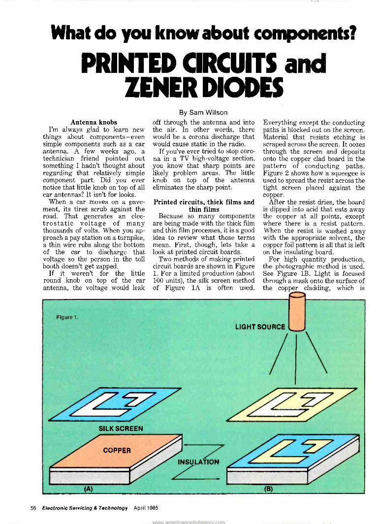
What do you know about components?
PRINTED CIRCUITS and ZENER DIODES
Antenna knobs I'm always glad to learn new
things about components - even simple components such as a car antenna. A few weeks ago, a technician friend pointed out something I hadn't thought about regarding that relatively simple component part. Did you ever notice that little knob on top of all car antennas? It isn't for looks.
When a car moves on a pave- ment, its tires scrub against the road. That generates an elec- trostatic voltage of many thousands of volts. When you ap- proach a pay station on a turnpike, a thin wire rubs along the bottom of the car to discharge that voltage so the person in the toll booth doesn't get zapped.
If it weren't for the little round knob on top of the car antenna, the voltage would leak
By Sam Wilson off through the antenna and into the air. In other words, there would be a corona discharge that would cause static in the radio.
If you've ever tried to stop coro- na in a TV high -voltage section, you know that sharp points are likely problem areas. The little knob on top of the antenna eliminates the sharp point.
Printed circuits, thick films and thin films
Because so many components are being made with the thick film and thin film processes, it is a good idea to review what those terms mean. First, though, lets take a look at printed circuit boards.
Two methods of making printed circuit boards are shown in Figure 1. For a limited production (about 100 units), the silk screen method of Figure lA is often used.
Everything except the conducting paths is blocked out on the screen. Material that resists etching is scraped across the screen. It oozes through the screen and deposits onto the copper clad board in the pattern of conducting paths. Figure 2 shows how a squeegee is used to spread the resist across the tight screen placed against the copper.
After the resist dries, the board is dipped into acid that eats away the copper at all points, except where there is a resist pattern. When the resist is washed away with the appropriate solvent, the copper foil pattern is all that is left on the insulating board.
For high quantity production, the photographic method is used. See Figure 1B. Light is focused through a mask onto the surface of the copper cladding, which is
Figure 1.
(A)
SILK SCREEN
INSULATION
LIGHT SOURCE
(B)
56 Electronic Servicing & Technology April 1985
www.americanradiohistory.com

covered with a photosensitive material. After this exposure, the board is developed with chemicals in a process similar to making photographic prints. All of the photosensitive material is removed except where it has been exposed. Exposed material acts like the resist in the silk screen process.
The next step is to spray the board with acid. The acid eats away all of the unwanted copper, leaving only the conducting paths. In a final step, the exposed photographic material is washed away.
The copper pattern on the printed circuit board may be up to 0.03 -inch thick (3x10⁻² in.). The procedures described for making printed circuits are similar to the procedures used for making thick film and thin film circuits.
If you look at a thick film circuit under a strong magnifier, you will notice it is similar in appearance to a printed circuit board. Tiny components are mounted on the surface, and the conducting paths make it look like a miniature printed circuit board. Thick film circuits are made small enough to be mounted in integrated circuit packages.
The procedure illustrated in
MASK
INSULATING BASE
Figure 2.
Figure 2 is used. However, in this case, a conducting material is deposited upon the substrate (which is the insulating base). The substrate and deposited material are heated to a temperature of higher than 750°C to fuse the con- ducting material onto the substrate.
An important difference here is that the process may be repeated several times using different pat- terns. Some parts of the overall pattern are made with resistive materials. So, the thick film pat- tern consists of both conductors and resistors.
Because thick film conducting paths are only about 0.0005 -inch (5x10⁻⁴ inch) thick, the name is misleading.
In thin film production, a mask is placed over a substrate material. And, in a vacuum, conducting material is passed over the mask in the form of a vapor or fog. It passes through the openings onto the substrate to form the conduct- ing paths. The thin film conducting paths are only a few angstroms thick. A typical value would be 0.000000015 inch (15x10-9 inch).
Using the zener diode The zener diode has been
discussed before, but this time it will be viewed from the standpoint of application. With a calculator and a little patience, you can design a zener-regulated power supply. Figure 3 shows the basic circuit.
The idea behind this circuit is that a small change in voltage across the zener diode causes a large change in the current through it. Suppose, for example
New Telephone Test Instruments
from B&K-PRECISION
Easy -to -use ... Fast ... Dependable Complete Telephone Product Analyzer-Model 1050 $1695 The only complete system for analysis and servicing of corded, cordless phones, auto dialers and answering machines.
--= - ....: 4
urrr0 , ? ur ttrnu . ®l ai le ®,. ti ' ..-.._`-----=G4 ®
Cordless Telephone Tester Model 1047 $895 All you need for full -frequency testing and alignment of base and portable units.
Telephone Product Tester Model 1045 $395 An in-store or in -field tester. Customer can check corded or cordless phone and auto dialers operation for all basic functions. Minimizes return of non - defective phones!
gi oo.
Air / 0 M
I,
Telephone Line Analyzer Model 1042 $19.95 Tells if problem is in the phone or externally in the line, ringing circuit or line cord. Ideal for personal, business and field service. Merchandising blister pack.
Available for immediate delivery at your local B&K-PRECISION distributor.
AKPREC/S/ON
DYNASCAN CORPORATION
6460 West Cortland Street Chicago, Illinois 60635.3121889-9087
International Sala. 6480 W. Cortland St.. Chicago, II. 60635 Canadian Sales: Atlas Electronics. Ontario
South and Central American Sales. Ema.re E.onrters, Plainview. NY 11803
Circle (36) on Reply Card
April 1985 Electronic Servicing & Technology 57
www.americanradiohistory.com

that the input voltage increases. Normally that would increase the voltage across the load resistance (RL). However, the increase in cur- rent through the zener diode causes a greater voltage drop across the series resistor (RS), and lowers the voltage across RL. The overall result is that the voltage across RL is nearly constant.
It is possible the input voltage is steady, but that there is a change in the output voltage due to a change in the load current. That change, in turn, increases the cur- rent through the zener. The resulting increase in voltage drop across the series resistor reduces the output voltage to the desired value.
If the input or output voltage decreases, there is a reduction in zener current. The voltage across R5 is reduced, and the output voltage is raised to the desired value. So, the zener circuit will regulate against changes in either the input or the output.
There are three possible condi- tions, and the design of the circuit is slightly different for each.
1. The input voltage may change, but the load is relatively constant.
2. The input voltage may be relatively constant, but the output current (and voltage) may change from time to time.
3. Both the input and output voltages are likely to change.
The following symbols are used in the simple equations.
R5 -the series resistance in ohms
VL -the desired output voltage. This is also the rated voltage of the zener diode.
Vin -the input voltage Iz -the current through the
zener diode IL -the load current Pz - the power dissipated by the
zener diode
Important! Double the value of Pz to get the power rating of the zener diode. Here are the equations -
For good regulation, the zener current must be at least 10 percent of the current through RS. These
OPTIMA ELECTRONICS TO ORDER CALL TOLL FREE 1.800.327-0224
POPULAR CAPACITOR ASSORTMENT BAGS (PC Mount)
mfd (1x2.2),(3.3),(4.7),(10),(22),(33),(47), (100),(220),(330),(470) -12 pca.
mfd (.47),(1),(2.2),(3.3),(4.7),(10),(22),(33),(47) 9 pcs. mfd (1),(2.2),(3.3),(4.7),(10),(22),(33),(47) 8 pca. mfd (1),(2.2),(3.3),(4.7),(10),(22),(33) 7 pcs. mfd (1),(2.2),(3.3),(4.7),(10) 5 pca.
Call and ask for our current flyer.
HORIZONTAL OUTPUT TRANSISTORS MONTHLY SPECIALS $2.50 ea. Mln. 10, 1 yr. Warranty BU208 (185) 1308K Sanyo TA7230P 2SD1341P Sanyo LA4445 $2.95
TRANSISTORS & I.C: s...MIN. 10, CAN MIX
2SC1118 ..$3.95 2SC1114 ..$3.75 MN8303...$3.95 2SC1124 ..$ .95 2SD871 ...$4.25 CX101G ..$10.50 CX103 ...$10.50 CX143A ..$10.50
D UPC1368H2$3.95 C UPC1387C.$3.75
(Subs CX557A)
C 221.103....$7.25 221.132.... $3.40 221.140... $10.95
C 221-158-01 .$4.75 221.175...$10.95 221-178....$7.00 221-179-01 $10.95 221.190... $10.95 221-193....$7.95 185-9-01 (trlac) $1.50
o
o o
o o
® 50V $3.25 @160V $3.30 @250V $3.95 @350V $3.75 @450V $2.95
$1.85 mIn. 10 $1.95
STEREO If's DM133 $5.95 DA101 $5.75 HA1388 $5.25 HA1398 $5.50 HA1398 $4.95 UPC1181 $1.00 UPC1182 $1.00 UPC1185H $3.50 2SC2580 $2.95 2SA1105 $2.95
GENERAL HI-DIV 3 $3.99 min 10
O Tun -O -Wash (24 oz.) $3.65 FreezIt (8 oz.) $2.25 F59A-59U Connector Crimp -on 300 for $30.00 Beta Video Heads $53.20
D VHS Video Heads $48.10 Panasonic Dual Antenna -Packaged (AT -19) min. 5 $2.99 TV/Game Switch (8AB21) min. 10 $ .89
Quantity Prices Available Letters of credit and all checks placed on deposit with Bank of Hallendate, FL. VISA & Master Charge accepted. Min. order $75. FOB Dania, FL.
Catalog $3, refundable upon order. SEND CHECK OR MONEY ORDER TO:
OPTIMA ELECTRONICS 2022 Tigertail Blvd., Dania, FL 33004
Phone (305) 920-3550 TOLL FREE: 1.800.327-0224
equations have taken that require- ment into consideration. 1. Regulation against input voltage changes with the load relatively constant RS = [V;n(Min)- VL] /1.1IL
Pz = {[Vin(Max)-VL] /RS -IL} VL
2. Regulation when the input voltage is relatively constant but the load current (and output voltage) tries to change. R5 = (Vin -VL)/1.1IL(Max)
PZ = { [(V.- VL)/RS - IL(Min)] }
VL
3. Regulation when either the in- put or output voltage is likely to change. RS = [Vin(Min)- VL)] /1.1IL(Max)
Pz = { [Vin(Max) - VJ /R5- IL
/R5- IL(Min) } VL
In all cases, the power dissipated by RS is: Ps = (V;n - VL) (1.1IL)
Double this value for the power rating.
NEW! NEW! NEW! NEW! NEW! NEW! NEW!
flew Product s Most Popular
ANTENNAS FOR: * PORTABLE TV's " AM/FM CASSETTE STEREO (boom boxes)
* WIRELESS TELEPHONES " SCANNERS ALSO- EASY TO READ
CROSS REFERENCE
Replacement VCR Belts ALL POPULAR KITS and INDIVIDUAL BELTS
36 KITS and 112 INDIVIDUAL BELTS
* REPLACEMENTS FOR CASSETTE
*REPLACEMENTS FOR 8 TRACK PLAYERS and RECORD CHANGERS
ALSO- EASY TO READ CROSS REFERENCE
WORKMAN ELECTRONIC PRODUCTS. INC. 75 Packinghouse Roach/ P.O. Box 3828
Sarasota, Florida 33578. Phone (8131 371 4242
TWX 810 864 0401 Workman Sara
z m
z m
z m
z m
z m
z m
z Cm
z m
Z Cm
NEW! NEW! NEW! NEW! NEW! NEW! NEW! Circle (22) on Reply Card
58 Electronic Servicing & Technology April 1985
Circle (23) on Reply Card
www.americanradiohistory.com

For Sale: Approximately 400 Sams Photofact folders from 53-1460. Make offer for one or all. Donald Lewis, Route 1, Central City, NE 68826; 308-548-2616
For Sale: More than $1400 worth of tools, test equipment, books and unused parts. Plus latest 24 issues of ES&T. Best offer over $250. Send large s.a.s.e. for information. Otmer Basham, 214 S. Craig Ave., Covington, VA 24426
For Sale: Out of production and difficult to find tubes; Sylvania SS -501 and R4410, Argon discharge tubes used in old models of big ship echo sounders, 6C6, 6D6, Sylvania 632-B, and many others. Write for requirements. Ed Pitsinger, Unitronix, P.O. Box 247, Galveston, TX 77553; 409-763-2207
Wanted: Flyback transformer for RCA CTC 38A color TV, part No. 62-21759. James Knutson, Box 373, Waterville, Quebec, Canada, JOB 8H0.
For Sale: Sams Photofact folders 399 to 2066 in six steel filing cabinets (four drawers). Also, Sams eight volumes 101 to 180. And RCA, Zenith, etc. manuals and volumes. Test equipment, tubes, tools. Send s.a.s.e. for complete price lists. Mack Kunzman, Jamke TV/Radio, 1051 Bale Lane, Calistoga, CA 94515
Needed: Schematics and service information for Brentwood 9009 printing calculator and for Texas Instruments TI -5050M printing calculator. Glen Spidal, 1325 SE Oak, #11, Hillsboro, OR 97123
For Sale: EICO 955 vacuum tube operated capacitor checker, 1 to 50 MFO range, excellent condition with manual, $45; RCA RF sine wave signal generator, type WR -50B, vacuum tube operated, 85kHz to 40MHz, ex- cellent condition with manual, $45. Knight vacuum tube operated volt/ohm meter by Allied Radio, good condition with manual, 1953 model, $30. Jerome Stanisz, 163 Richard Ave., Elmhurst, IL 60126; 312-832-7831.
-PREPARE- For The Future
1985 National
Professional Electronics Convention
INFORMATIVE SPEAKERS MANAGEMENT SEMINARS TECHNICAL TRAINING NAT'L. SERVICE CONFERENCE NEW PRODUCT DISPLAYS SPONSORED MEALS TENNIS/GOLF OUTINGS
Sponsored by the National Electronics Sales & Service Dealers Association and the International
Society of Certified Electronics Technicians
Hartford CT PHiltonW August 5-10 Send for more information ana an application to
NPEC, 2708 W. Berry St.. Ft. Worth, TX 76109: Ph (817) 921-9061
Name
Address
State Zip
For Sale: Sencore TC 28 tube -and transistor tester, $100. Mark IV tuner subber ac/dc, $50. EICO 944 yoke and flyback tester, $30. Sencore BE156 dc bias supply (new), $25. VIZ WP25A isolation transformer, $50. V. Granzella Jr., Box 190, Wheatland, MO 65779; 417-282-6506
For Sale: Tekfax 105-13-14-15. Tekfax/Profax 1978 -Dec. 1984. More than 600 schematics, $24. TAB color TV service manuals, 18 volumes, Admiral - Zenith, $14. Sams AR -30-35-67-81, $3 for all four. Retired. Bob Begun, 1056 Fraser St., Aurora, CO 80011; 303-366-3980
For Sale: Sencore VA48 analyzer, like new, only used once, includes TR219 horizontal attenuator, manuals leads and probes, $1000 (includes shipping). G. Jones, 3312 Werber St., Orlando, FL 32806; 305-859-6573.
Needed: Dual volume control and switch (new or used) for Panasonic AM/FM stereo tuner amplifier, model No. 7671, (Sams 960-7). William J. Maida, 341 Isabella Drive, Longwood, FL 32750.
For Sale: RCA CRT test jig model 10-J-106 with 38 assorted chassis adapters, $300 plus shipping. Linda Rollins, 2991 Clay, Mora -Mi Apt. 45, Paducah, KY 42001.
Needed: Schematic/service manual for CB transceiver, 40 channel, model Pony 410, Mfg. Far East Filtron Co. Heath SM -2420 or SM -4130 frequen- cy counter and Microcraft CSIF code reader. Caswell Davis Jr., 601 Delmar, Apt. 2, San Antonio, TX 78210.
For Sale: B&K Precision model 1077B, $359 plus shipping. M.E. Andrews Jr., Box 91, Exeter, RI 02822.
Needed: Answering machine service information and schematics. Will pay for copying, will buy or will exchange for cordless telephone or TV informa- tion. Please send list. TV Shop, 22 Central Ave., Mechanicville, NY 12118; 518-664-8631.
For Sale: Heathkit IM distortion analyzer model IM -5248, $125 plus UPS. Also, Sprague model TO -6A capacitor analyzer, like new $150 plus UPS. A.J. Lemke, Al's Service Center, 10004 206th Ave. NE, Redmond, WA 98053.
Needed: Schematic or service manuals for 30 track tape recorder type FA -5394/1 through 5, made by Sound Scriber Corp. for the FAA under contract No. FA -2270. Will pay for manuals. Mark Reeder, Michris Elec- tronics, 288C, Route 73, Berlin, NJ 08009; 609-768-9383.
Warranty on
es a tWEa \oest-cost there's p, P st\y
Depe11d8bE.X 525 mayob f features.. a PumP \s for use
tes Putg1P 1he but \t,s
t1\ en PC boards Mode\ 5505in0
and the der eXents from
mfÓ(tigU et
oPeeae\ s non c\o99
ComP°on,tao\.tEis-1000by panel
Ccn shop.
Gaff °rite97, vlbran Equipment With eraP
ne-re9°\ E E..)(-52.5 in yated Production .
5165g_1
temperature -regulated
Pneed the detai\s. Automated N Y. 1
today for a1PeConiC Pve., M
CorX,y10 228.2120
TW DEPEND S
ON Circle (24) on Reply Card
April 1985 Electronic Servicing & Technology 59
www.americanradiohistory.com

Wanted: Schematic and parts list for commercial trades institute of Chicago, vacuum tube VOM model VT -20. John Marsh, 55963 Onaga Trail, Yucca Valley, CA 92284.
Wanted: TV/VCR equipment for new shop, Sams and manufacturers manuals, Sencore VA62-SC61 and other Sencore and B&K equipment. Howard Hitzeman, 123 Crestwood Lane, Largo, FL 33540; 813-581-3250.
For Sale: Winegard SC70355 satellite receiver with 36 -power supply and actuator, new, $810. Robert Piper Jr., Rural Route 3, Benton, IL 62812; 618-724-9050.
Wanted: Sams Photofact folders from 1200 to near present. Complete un- broken series only. Will inspect and pick up within 300 miles of my location. No file cabinets needed. C. Hugh Harrell, P.O. Box 6691, Newport News, VA 23606.
For Sale: Hewlett-Packard 334A distortion analyzer, excellent condition, $1500 or best offer. Brian Findlay, 4 Barnesdale Road, Nashua, NH 03062; 603-882-9812.
For Sale: B&K Precision 415 generator, $75 plus $5 for shipping. Joe Larsen, Joe's Repair Service, 60835 N. Highway 50, Montrose, CO 81401.
For Sale: Hewlett-Packard RF power meter with 8478B thermistor mount, $95. Heath IM -2202 DMM, $60. Both like new with cables and manuals. B&K color generator, very good condition with cables, no manual, $50. D.G. Piacentini, 12 Joyce Road, Plainview, Long Island, NY 11803; 516-935-8096.
For Sale: Sencore SG165 stereo AM/FM analyer, new (still in carton), retiring, $995. Al Nikora Sr., 5298 Argyle Court, Sterling Heights, MI 48078; 313-268-6938.
Wanted: Adapter to play 45RPM 7 -inch records on a Garrard model 60MK II record player. Paul Capito, 637 W. 21st St., Erie, PA 16502.
Wanted: Schematic for Panasonic 25 -inch color television model CT 5221/CH#62HMN. Howard Waldren, 3 Vincent Place, Oakdale, NY 11769.
For Sale or Trade: QST 1971 -Aug. -Dec., 1972 -Jan. -Aug., Nov., Dec., 1973 -Feb., April, June, July. Make offer. William J. Maida, 341 Isabella Drive, Longwood, FL 32750.
QUALITY PARTS AT DISCOUNT PRICES! SUB -MINIATURE
D TYPE CONNECTOR
',Iet4itllni SOLDER TYPE SUB -MINIATURE
CONNECTORS USED FOR COMPUTER HOOK UPS
DB -15 PLUG $2.75 D8-15 SOCKET $4.00 DB -15 HOOD $1.50 DB -25 PLUG $2.75 DB -25 SOCKET $3.50 DB -25 HOOD $1.25
"PARALLEL" PRINTER CONNECTOR
SOLDER STYLE 36 PIN MALE USED ON "PARALLEL"
50 EACH DATA CABLES
SEND FORS
MINIATURE TOGGLE SWITCHES
ALL ARE RATED 5 AMPS @ 125
S.P.D.T. VA
(on -on) SOLDER LUG TERMINALS $1.90 EACH 10 FOR $9.00 100 FOR $00.
S.P.D.T. (on -on)
P C. LUGS. THREADED BUSHING $1.00 EACH 10 FOR $9.00 100 FOR $90.00
L. E. D: S STANDARD JUMBO
DIFFUSED RED 10 FOR $1.50
GREEN 10 FOR $2.00 YELLOW 10 FOR $2.00
P11 FLASHER LED 5 VOLT OPERATION illiRED JUMBO SIZE
$1.00 EACH
BI POLAR LED 2 FOR $1.70
2 AMP SOLID STATE RELAY
SIZE 1,2..
T4" HIGH
CONTROL: 36-6 ROC
TTL compatible LOAD: 120 Vac @ 2 amp
$2.50 each 10 for $23 DO
CASE STYLE HC33/U CRYSTAL
2 MHZ COLORBURSTI 3579.545 KC
$3.50 EA $1.00 EACH
NE 1985
S.P.D.T. (on -on)
P C STYLE. NON -THREADED BUSHING. 754 EACH IO FOR $7.00
S.P.D.T. (on -off -on) NON -THREADED PUSHING. P C STYLE 75e EACH TA FOR $7.00
1 BON S. VERMONT P.O. BOX 20406 LOS ANGELES, CA 90006
Lr
ii _ 13 VDC RELAY
\ CONTACT: S. P.N.0
I1 lI10AMP@120VAC .'FI' ENERGIZE COIL TO
' OPEN CONTACT COIL 13 VDC 650 OHMS
SPECIAL $1.00 EACH
X48 PAGE CATALOG FREE!
SOLID STATE BUZZER
STAR RSMB-06L 6 VDC. TTL
COMPATIBLE.
$1.00 EACH
10 FOR $9 00
120V INDICATOR
NEON INDICATOR RATED 120 V 1/3 W
MOUNTS IN 5/16" HOLE 754 EACH RED LENS
10 FOR $7.00 100 FOR $65.00
L ELECT OAICS CORP TOLL FREE ORDERS 1-800-826-5432
(IN CALIFORNIA: 1-800-258-6666) AK, HI, OR INFORMATION (213) 380-8000
QUANTITIES LIMITED FOREIGN ORDERS MINIMUM ORDER 51000 INCLUDE SUFFICIENT USA 5300 SHIPPING SHIPPING
NO C O 0' CALIF RES ADO 61 2
Circle (25) on Reply Card
EDGE no/
CONNECTORS
22/44 22/44 GOLD PLATED CONTACTS
156 CONTACT SPACING
$2.00 EACH 10 FOR SIR'Il
SWITCHING POWER SUPPLY
INPUT: 14 Vac -25.5 Vac
OUTPUT: +12 Vdc @350 ma + 5 Vdc @1.2 amp - 5 Vdc @ 200 ma
SIZE: 414" x 414" x 144" high
$5.00 each
Wanted: Schematic and information for a J.C. Penney MHF stereo model 1802A. M. W. Smith, 400 Brandon Road, Richmond, VA 23224.
For Sale: Complete Video servicing package: Sencore models SC61, VA48, CR70, PR57, LC53 and TF46, all in mint condition. Includes accessories, manuals and scope cart. Also, 360 Sams Photofact folders, filing cabinet and other miscellaneous service literature. Leaving service business, must sell as a package. Asking $5500. Frank Ward, Route 2, Box 575, Woodville, MS 39669; 601-888-4687.
Wanted: Ryder radio manuals 17, 19, 21 and 23. Also 1920s radio tubes 199s, WDIIs 200Ás, 201As, and Atwater -Kent radios any condition. Charlie Alford, 222 N. San Jacinto Ave., San Jacinto, CA 92383.
Needed: Schematic for Magnavox model 355B, style C101-219, chassis No. CR202A. Also, one audio circuit part for Admiral 5R36N, chassis No. 5R3, original part No. 63-B6-14. Lew Wollaston Radio & TV, 1504 Big Horn, Alliance, NE 69301; 308-762-3003.
For Sale: B&K 501A curve tracer, $130, B&K 2040 CB RF signal generator, $250. B&K 1040 CB service master, $150. Everything complete and in first-class condition. Rolla H. Long, Long's TV, 720 Goshen St., Salt Lake City, UT 84104; 801-533-8093.
For Sale: FC45 frequency counter, $250. Sencore PS163 scope, $300. Sen - core VA48 (updated and calibrated), $800. EICO 633 CRT tester with adapters, $80. UPS included. Bill Bechtold, 7429 Frederick, Omaha, NE 68124; 402-397-2461.
For Sale: Century CRT -2 tester rejuvenator, $35. Heathkit color bar generator model TG -62, $40. TECH signal generator model TE -20, 220V, $35. Gad Barzily, 84-39 120th St., Kew Gardens, NY 11415.
For Sale: Sencore DVM 36 pocket portable DMM, like new, complete with manual, probes, ac adapter and instruction cassette, $65 plus$2 shipping. Please send a U.S. postal money order. Norman Palus, 303 E. Lutton St., New Castle, PA 16101.
For Sale: Video Tune -Up program disk for Commodore computer (64-SX-64). Program generates video test patterns and runs an automatic alignment test. Used but is 100 percent operational, $15. Made by Solas Products. Mark Kruse, Videonics Inc., 911 Township Line Road, Nor- ristown, PA 19401; 215-362-5028.
Business Opportunity
It's plenty tough being an electronics sales and service dealer these days.
That's why we're working so hard to make it easier for you to operate a cost-effective business.
NESDA offers business contacts, technical and management certifi- cation, substantial savings on bank - card and insurance rates - and that's just the beginning!
NE SDA members are kept informed about industry develop- ments and are offered the most comprehensive managerial and technical training programs available. Besides, NESDA is your representative at the national level - including your voice to manufacturers and the agencies of the federal government.
Opportunity knocks . NoIIDnDIElcclranlcs solesE
Answer it! NESDA Service Dealers Associolion
For more information -and an application, write to: NESDA, 2708 W. Berry St., Ft. Worth, TX 76109; Ph (817) 921-9061
Name
Bus. Name
Address
State Zip Phone
Member of State ; Local Assn
60 Electronic Servicing & Technology April 1985
www.americanradiohistory.com

For Sale: Dual trace model 422 Tektronix scope, $400. Angelo Alessi, 29 Cross St., New Windsor, NY 12550; 914-562-9152.
For Sale: B&K model 1077B analyst. Also, B&K 415 alignment generator. Both in excellent condition, $200 each. Bob Evans, 2318 Big Horn Ave., Cody, WY 82414; 807-587-5251.
Needed: Schematic and/or a replacement for the IC on GM theft deterrent module No. D2 666. R.C. Chatfield, 363 S. Bluefield Place, Tucson, AZ 85710.
For Sale: B&K 1077B analyst, $350. B&K multimeter 290, $125. B&K transformer checker 520, $75. Stan Hayman, 19707 Turnberry Way, N. Miami Beach, FL 83180.
For Sale: Soar 50MHz dual trace scope, $750. Sencore VA48 video analyzer, $800. Sencore CR70 CRT analyzer/restorer, $700. Other items for sale, too. All equipment in like -new condition with accessories and manuals. Shipping included. Mike Powers, 312 E. Chestnut, Clarinda, IA 51632; 712-542-5847 or 712-542-2161.
For Sale: Heathkit IT -2250 auto ranging capacitance meter, $40. Subber Mark IV-CUV UHF/VHF tuner sub, ac battery, $45. Covar color bar generator, $25. B&K Precision scope, 10MHz model 1466, $400 firm. R.E. Carron, 3503 Hudson Circle, Manahattan, KS 66502; 913-776-4100.
Needed: Service manual/schematic for Thomas Electronic Organ. Will buy or copy and return. Stanley Kowalski, 220 E. Frederick St., Ironwood, MI 49938; 906-932-1410.
Pot -luck Sale: Mixed radio and TV tubes, new and used, $1 each plus ship- ping, minimum quantity, 50. Jerry Stanisz, 163 Richard Ave., Elmhurst, IL 60126; 312-832-7831.
For Sale: Sencore CA55, like new, $375. Sencore DVM 38, used less than one hour, $400. Wanted: Two EAF 801 tubes for old Grundig stereo. Dick Lopez, 10212 New Hampshire Ave., Silver Spring, MD 20903; 301-439-5333.
Wanted: Factory operation manuals for Hickok model 610A television, FM alignment signal generator and Paco model Z-80 audio signal generator. For sale or trade: B&K model 1460 triggered sweep scope and Heathkit IG -18 sine -square generator. Please send price, cost and/or offer. Archer/Brighton TV Electronics, do Stuart Koniarski, 7816 S. Kolmar, Chicago, IL 60652.
CA28 UNIVERSAL PICTURE TUBE ADAPTER NOW YOU CAN USE YOUR CRT/RESTORER/
REJUVENATOR/CLEANER ON ANY COLOR CRT YOU DO NOT NEED TO BUY A NEW CRT TESTER.
SAVE HUNDREDS OF DOLLARS "THIS IS THE ONLY ADAPTER YOU WILL NEED" -USE ON NEW IN -LINE & ONE -GUN TUBES -
If your tester is the CLEANER/RESTORER type or the REJUVENATE type, you can use the function on your present machine or any Color Tube listed from a 9" to a 26," Including foreign types. Checks Quintrex, Japanese Miniature Base, Japanese In -Line, Sylvania, and GE 90 Degree Infine, New Sony Trinitron, Zenith Special In - line, European 110 degree in -line, Sylvania 100 degree Color Tri -Potential, RCA 90 degree In -line, 110 degree Color, 90 degree Button Base, Large Trinitron, Small Trinitron.
Use with CRT Tester/Restorer/Rejuvenator. CHECKS: QUINTREXINLINE-TRINITRON-TRI
POTENTIAL - PINLESS - JAPANESE - EUROPEAN 90°; 100°, 110° ALL CRTs
VIDEO GAMES -COMPUTER TERMINALS, COLOR T.V. SIZES 9" thru 28" SCREENS. MONEY BACK GUARANTEED
to solve all your CRT Testing problems, Obsolescence Proof Perpetual Set -Up Manual, CA28 Adapter Klt with Sockets.
**CHECKS OVER 2500 COLOR TYPES' REPLACES OVER 85 ADAPTERS
B&K, BELTRON, SENCORE, CONAR, HEATHKIT
REM, EICO, RCA, ALL OTHERS
Call Toll Free 1-800-331.8688
Comes with complete EASY -to -follow Instruction Manual and Picture Tube Index.
A MUST FOR THE TV TECHNICIAN CALL US OR WRITE
COD. Send Check or Money Order. CA -28 Kit $61.95. add $2.00 shipping and handling. Visa & Mastercard accepted.
DANDY MANUFACTURING CO. 2323 Gibson, Muskogee, Oklahoma 74403
918-682-4286
Wanted: Knight 83YX123 sweep generator with manual, and manuals for Knight 83Y125 VTVM and 83Y135 signal tracer. Tekfax volumes 100, 102-105 and 115 to end. C. T. Huth, 130 Hunter St., Tiffin, OH 44883.
For Sale: Sencore harmonic generator, $15; B&K 820 digital capacitance meter (works intermittently), $40; B&K 1827 frequency counter, new, $75; Sencore RC substitutor, $25, B&K 1471B dual trace scope (one channel in- operative), $200. V. Granzella, Jr., Box 190, Wheatland, MO 65779; 417-282-6506.
Wanted: Sams Photofact folders. Will pay postage and 75¢ each for sets 1200-1499, $1 each for 1800-2100. Will consider buying complete set, and other service data. Willy's Electronics, P.O. Box 56595, North Pole, AK 99705; 907-488-1307.
For Sale: B&K CRT tester model 456, never used. Included are operating manual, two set-up charts (old and new) and six adapter sockets. $75 plus shipping. Send s.a.s.e. for information. Also, high impedance, low capacitance scope probe for precision scope. New from B&K, model SP -5A, original carton. $10 plus postage. Jag's Radio & TV, Jos. A. Gontarz, 14 Rudolph Rd., Forestville, CT 06010.
For Sale: Sencore VA48 Video analyzer, $800; Sencore Super Mack CRT tester/restorer CR31A, $400. Both excellent. Larry R. Bell, 5506 Mesa Ridge Lane, Columbus, OH 43229; 614-882-8055.
For Sale: Heathkit AJ32 tuner with amp -both, $150. National NC 173 all - band radio, needs power transformer, $50; Lectrotech V7 Vectorscope, $100; Heathkit IG14 post marker generator, $100; Army lab signal generator and audio oscillator, $100 each. William Timm, 2400 Progress, Eureka, CA 95501; 707-445-8345.
Need: Schematics, manuals and parts information for Advent projection - type large screen televisions, models VB125 and 710. Will pay copy/ship- ping expenses, or will copy and return. Bill Hamilton, 13 Overbrook Drive., Kirksville, MO 63501; 816-665-1427.
Need: Schematic for Masterworks stereo cassette player/recorder, model M-400. Solenoid dS-10B, DC 100V, 8000. Schematic and owner's manual for Masterworks SQ AM/FM 8 -track, serial No. H340-03374, model not known. Desire name and address of anyone knowing where to get parts, schematic or repair. For these and other items needed, contact M.J. Stan- ton, 1725 Rear Lafayette St., Scranton, PA 18504.
Over 27 solc!erîn options right at your fingertips. With Sterling® you can combine 15 miniature soldering irons with 23 different tips to match your exact soldering need.
Irons range from 575° to 850°F;5to 25 watts; and 4.5 to 24 volts. Send for the name of your nearest distributor and get a free mini -catalog on the mini -irons that are mighty on performance.
WAHL CLIPPER CORPORATION Sterling, Illinois 61081 (815) 625-6525
Circle (26) on Reply Card Circle (27) on Reply Card
April 1985 Electronic Servicing & Technology 61
www.americanradiohistory.com

PRB... OFFERS THE PROFITABLE SYSTEM FOR SELLING VIDEO RECORDER BELTS
The PRB stock number describes the required belt. You just size the belt on our handy MEASURE-ABELT gauge and you'll have all the info needed to find your belt. The PRB System is fast, easy and profitable! For details on our profitable belt system and the complete line of PRB electronic com- ponents just call toll free ...
National In Wisconsin 1.800.558.9572 1.900.242.9553
Business Number TLX 1.414.473-2151 4994411 PRB USA In Canada call collect: 1.813.225.5003
PRB FL-GU PROJECTOR RECORDER BELT
200 Clay Street, Whitewater, WI 53190
Circle (28) on Reply Card
ATTENTION
TECHNICIANS
* JOB OPENINGS
* MONTHLY TECHNICAL
TRAINING PROGRAM
* BUSINESS MANAGEMENT
TRAINING
* LOW COST INSURANCE
* CERTIFICATION
* TECHNICAL SEMINARS
All of this in a nonprofit international association for technicians
FIND OUT MORE:
i/ \ / K\\
ETA /Ì R.R. 3 Box 564 Greencastle, IN 46135
-
Literature
A 6 -page folder from Ballantine Laboratories, Boonton, NJ, catalogs and details an extended new family of rugged, modular probes for oscilloscopes and meters. Ballantine has adapted many of the military design parameters required for such devices to its commercial line.
Charts and photographs detail specifications for the full line of Ballantine probes. The catalog also details specifications and applica- tions for a high voltage RF detec- tor probe, model 10851A.
Circle (100) on Reply Card
AEMC, Boston, MA, has re- leased the 1985 edition of their catalog, Testing and Measuring In- struments for the Professional. The catalog covers the AEMC pro- duct line of electrical test and measurement instruments and re- lated products, including light - meters, temperature probes, and environmental recorders. Product features and applications, com- plete specifications, photographs, sizes and weights, ordering infor- mation and available accessories for each product are included.
Educational materials are in- cluded on easily located, color - coded pages. Background informa- tion is incorporated to help the user understand general operating principles and to aid in assessing test results for validity and ac- curacy. Topics include insulation resistance testing, ground resis- tance testing, power factor measurement and correction, clamp -on current probe selection, and ground fault detection.
Circle (101) on Reply Card
RCA Distributor and Special Products Division, Deptford, NJ, has issued an updated catalog on RCA remote controls for video in- struments. This catalog encom- passes current RCA remote con- trols and superseded types. Photos for visual identification and cross- references by type number and by instrument number are included. The catalog is available from RCA
Parts Distributors or through RCA Distributor and Special Prod- ucts Division.
Circle (102) on Reply Card
M.M. Newman Corporation, Marblehead, MA, offers a wall chart featuring standard slide -on tips available for Antex model C, G, and CTC miniature soldering irons. The Antex Tip Chart fea- tures more than 35 standard styles and sizes of slide -on tips made from a special copper alloy and plated with iron, nickel and gold.
Complete with actual size il-
lustrations, the 81/2" x 11" Antex Tip Chart provides the diameter; tip shapes, including spade, chisel, needle and reshapeable blanks, plating material and correspond- ing part numbers for ordering.
Circle (103) on Reply Card
A free booklet on how to take care of a computer to prevent data loss and downtime is available from Read/Right Products, a part of The Texwipe Company, Upper Saddle River, NJ. Entitled The Care and Feeding of Your Computer, the 16 page, illustrated booklet points out that computers require care because the mechani- cal components, such as the disk drive, printers and most key- boards, may fail unless they are kept clean. Static electricity is another serious problem that can lead to data loss.
The types of contaminants that cause problems in disk drives, CRT screens, keyboards, printers and computer housings are discussed. The booklet also explains cleaning procedures and briefly mentions that Read/Right Products offers a full line of cleaning kits and in- dividual products for office equip- ment and computers.
Circle (104) on Reply Card
BBC-Metrawatt/Goerz, Broom- field, CO, has published three booklets designed to help buyers evaluate and compare low-cost analog and digital multimeters. The three booklets point out many of the factors to consider when buying a multimeter, and include a handy checklist of features to use when shopping for low-cost hand- held DMMs.
Circle (105) on Reply Card
62 Electronic Servicing & Technology April 1985
www.americanradiohistory.com

Answers to quiz Continued from page 16.
1. B. This is an example of the reciprocity theorem. The amount of voltage, circuit layout and resistance values are not a concern in this case. 2. C. In both cases, the gain is 1.
3. B
4. D. It is the symbol for a constant -current diode.
5
A B L
o o 1
0 1 0
1 0 0
1 1 1
6. A
7.C.AB A + B
is the same as
8. B. A snubber is a series R -C circuit connected across the SCR. It prevents an in- ductive kickback from turn- ing on the SCR even though its gate is not in a conduction mode.
Ille 9. and 10. Figure a shows the circuit. The voltage across R is 6V and the current through it must be 0.15A. By Ohm's law: R = V/I = 6/0.15 = 400
Advertising rates -..ied Section are 75 cents per word, each insertion, and must be accom- panied by payment to Insure publications.
Each initial or abbreviation counts a full word.
Minimum classified charge is $15.00.
For ads on which replies are sent to us for forwarding (blind ads), there Is an additional charge of $25.00 per insertion to cover department number, processing of replies, and mailing costs.
Classified columns are not open to advertising of any products regularly produced by manufacturers unless used and no longer owned by the manufacturer or distributor.
FOR SALE
SUBSCRIPTION TV MANUAL, covers all three major scrambling systems, only $12.95. Includes theory, cir- cuits, waveforms and trouble shooting hints. Save your VIDEO GAME CARTRIDGES on EPROM with out EPROM duplicator. Plans $9.95. Catalogue $2.00, refundable. RANDOM ACCESS, Box 41770A, Phoenix, AZ 85080. 1-85-tfn
AUTOMOBILE RADIO and tape replacement parts. Delco, Chrysler, Philco-Ford, Motorola, Panasonic and many others. Large inventory. Laran Electronics, Inc., 3768 Boston Road, Bronx, NY 10469. (212) 881-9600. National (800) 223-8314, NY State (800) 446-4430.
1-85-tf n
WE LOCATE hard to find TV schematics. Immediate reply. Send $13.50 with make and model to WB ELEC- TRONICS, P.O. Box 1314, Falls Church, VA 22041.
4-85-1t
BOOTLEGGERS BIBLE for CB Modification $12.95, CB Radio Repair $10.95. Linear Amplifier Planbook $14.95, kits, etc. Catalog $1.00 refundable - APS, POB 263 Newport, R.I.02840 401-846-5627. 12-84-tf n
COLOR PICTURE TUBE Rebuilding Equipment. In ex- cellent condition, everything to build good tube. Train- ing available. John Smith, Box 34, Fountain, CO 80817.
4-85-2t
INDIVIDUAL PHOTOFACT FOLDERS (Not sets) #1 to #1400 $3.00 first-class postpaid. Loeb, 414 Chestnut Lane, East Meadow, NY 11554. 4-85-3t
SAVE BIG BUCKS ON INTEGRATED CIRCUITS AND TRANSISTORS. WHOLESALE PRICES. LARGE IN- VENTORY. WRITE: JILCO INTERNATIONAL, 439 MAIN ST., SUITE 2B, EAST ORANGE, NJ 07017.
2.85-4t
SCRAMBLED TELEVISION, encoding/decoding. New boók. Theory/circuits, $9.95 plus $1 shipping. Work- shop, Box 393ES, Dept. E, Bethpage, NY 11714.
1-85-tf n
RCA WV87B VTVM $35.00, Triplett 3433 AM/FM signal generator $50.00. Eico 377 sine/square wave generator $45.00. You pay shipping. PH702-456-9048. 4-85-1t
BELDEN RO8/U Coaxial Cable, #9058. This Is the best. Duobond II/Braid/Duobond Plus. Normally available in 1000 ft. rolls only. Three Incredible shields. Foil over foam core gives 100% shielding. 77% aluminum braid. Foil wrapped over the two inner shields (Duo - bond Plus). 100 ft. $24.00, 200 ft. or more 10% dis- count. Crimp Connectors for RG6/U cable with at- tached '/z" crimp ring, (with purchase of cable only). 10 for $3.00, 50 for $9.00, 100 for $15.00, check or money order. Postpaid. (609) 877-7480. DANIELSON ELECTRONICS, 6 Garnet Lane, Willingboro, NJ 08046.
3-85-2t
SONY - PANASONIC - RCA - ZENITH EXACT RE- PLACEMENT PARTS -SONY PARTS AND TRINI- TRON SPECIALISTS. LARGE INVENTORIES. CALL 516-678-1700 OR WRITE WITH PART NEEDED. GREEN -TELE -RADIO, 172 SUNRISE HIGHWAY, ROCKVILLE CENTER, NY 11570. 1-85-tfn
SINCE 1950
LEADING SPOKESMAN
TRADE INFORMATION DISPENSER
WATCHDOG
NATESA SCOPE STANDARDS YARDSTICK
CONSUMER RELATIONS
PROBLEM SOLVER
CONCISE PRACTICAL BUSINESS OPERATIONS MANUAL
SERVICE CONTRACT MANUAL
CUSTOMER PLEASING PROFIT PRODUCING ORDER FORMS
PARTS PROCUREMENT EXPEDITOR
SERVICE BUSINESS
DIVERSIFICATION PLANS
TECHNICIAN DEVELOPER
VIDEO HOOK-UP DIAGRAM MANUAL -Shows how to hook-up TV, VCR, Satellite, Stereos, Multi -sets. $6.00. NorthStar Video Services, Dept. E, P.O. Box 1992, Hollywood, FL 33020. 3-85-3t
FULL LINE of TV converters. Wireless and manual compatible to Jerrold and Oak Systems. This month's special the Technica 140CHL stereo and video com- patible out -put wireless converter. The only unit with a wireless volume control adjustment only $159; cable 15dB Amp In -line type only $20. RED COAT ELEC- TRONICS, new address and phone: 104.20 -88th Dr., Forest Hills, NY 11374, Tele: (212)459-5088. Catalogue $3 for specials. 10.84 -tin
TUBES -Receiving, Industrial and Semi -conductors, factory boxed. Free price list. Low; low prices. TRANSLETERONIC INC., 1365 -39th St., Brooklyn, NY 11218E, 800-221-5802, 212-633-2800. 1-85-tfn
TV TROUBLE ANALYSIS TIPS. Over 300 symptoms/ remedies by circuit area; tough ones over the years. Save time and money. Send $12.50 to CHAN TV, 8151 Grandview Rd., Chanhassen, MN 55317. 1-85-tf n
MAKE TELEPHONE answering machine servicing simple & professional. Without tying up your phone lines, our ring simulator will activate any machine on the market. You can haar the outgoing message, give your message, and also have the availability to check machines that have remote capability. Send your check for $85.00 made payable to PSI, INC, to cover cost of machine shipping and handling or call (201) 845-6669. PSI, Inc. Is located at: 34, Route 17 North, Paramus, New Jersey 07652. 4-84-tf n
TUBES FOR TV AND RADIO -350 ea. Washington TV Service, 1330 E. Florence Ave., Los Angeles, CA 90001.
11-84-12t
SAVE TIME ON COLOR TV REPAIRS. Over 3,000 tips on 31 brands. 116 page manual, $21.00 PP. Send check or M.O. to: A.F. FERNANDEZ, P.O. Box 546110, Surf - side, Florida 33154. 4-85-2t
SINE WAVE QUESTIONS? Trouble shooting, align- ment manual; $6.00 S/W Pay TV patent secrets; $10.00. Both; $14.00. STV Authorization/control infor- mation; $2.00. Signal, Box 2512-E, Culver City, CA 90231. 4-85-1t
April 1985 Electronic Servicing & Technology 63
www.americanradiohistory.com

FOR SALE (CONT.)
HOW TO LOAD AND UNLOAD a console TV of 200 pounds in a van or truck. This can be done easily by a 70 -year old man alone. For information, write to FAMI- LY N, 5802 N. Armenia, Tampa, Florida 33603. 3-85-3t
MOTOROLA MX -350 including Nicad and rubber duck antenna. Needs repair. $150.00 PH702-456.9048.4-85-1t
COMPLETE video servicing package, SENCORE models: SC61, VA48, LC53, CR70, TF46, PR57. All ex- cellent condition. All available asscs. 400 SAMS with cabinet and other service literature. Must sell. $5200.00 neg. Phone 1-601-888-4687. Write Frank Ward, Rt.2, Box 575, Woodville, MS 39669. 4-85-1t
HELP WANTED
AUDIO/T.V. TECHNICIAN NEEDED: Top pay for ex- perienced Audio and/or TV repair technician in sunny California. Write or call The Audio/Video Clinic, 3623 State St., Santa Barbara, Calif. 93105 (805) 682-6822.
4-85-1t
SITUATION WANTED
AUDIONIDEO TECH Desiring position. All locations considered. Write PO Box 294, Philadelphia, MS 39350. Knowledgable in Car Stereos, Stereos, N's, VCR's. 3-85-2t
EDUC.-INSTRUCTION UNIVERSITY DEGREES! Economical home study for Bachelor's, Master's, Doctorate. Prestigious faculty counsels for independent study and life experience credits. Free information-Richard Crews, M.D. (Har- vard), President, Columbia Pacific University, 1415 Third St., Sept. 2884, San Rafael, CA 94901; Toll Free: 800/227-0119; California: 800/552-5522; or 415/459-1650. 4-85-15
HELP NEEDED: Need help with C.I.E. Course 16 com- pensation will be paid. Please write to P.O. Box 504. North East, MD 21901. 4-85-1t
WANTED
PICTURE TUBE REBUILDING EQUIPMENT, working or not, write or call: Chicago Television, 633 North Semoran Blvd., Orlando, Florida 32807. Ph. 275-9543.
11-84-9f
WOULD LIKE TO BUY one or more of the following '66- '69 Sylvania color television sets: Model Nos. CF460, 461, 462, 463, or 464 also. Model Nos. CF503-1, 504, or 505K. Need not be in working order. Call collect (312) 876-1900 Rosemary Groenwald. 4-85-1t
BUSINESS OPPORTUNITIES
THIS IS PARADISE! In mountains of Northern Califor- nia, 4 hours from San Francisco. Electronic repair business, selling for health reasons. Building/Business/Living Quarters/Equipment $165,000. (916) 872-1962. 3-85-21
AUDIO REPAIR SHOP-Going out of business. Soundtechnology, B&K, Fluke test equipment; 4500 service manuals; Many OEM and replacement parts and supplies; Best offer over $7500. Call 301-744-1544 for details or write B&B Electronics, 5310 Edmondson Ave., Catonsville, MD 21229. 4-85-1t
PICTURE TUBE REBUILDING EQUIPMENT, one man operation, full training and technical assistance. Buy with confidence from experts in the field. Call or write: Chicago Television, 633 N. Semoran Blvd., Orlando, Florida 32807, Ph. 305-275-9543. 11-84-9t
TV SALES & SERVICE BUSINESS: Sunny San Diego, same beach location for 13 years. Price $66,000 plus stock, down $22,000. Call Lauer, Lauer, Penn & Associates, (619) 296-5000. 4-85-1t
FOR SALE: TV sales and Electronics Service Business -2100 square feet. Located in northeastern Wisconsin. Buildings, parts Inventory, test equipment, and service manuals included in price. Two rented apartments upstairs for extra income. Owner retir- ing -Call 414-834-2135. Firm at $47,000.00. 4-85-1t
ATTENTION ELECTRONIC TECHNICIANS
Highly Effective Home Study BSEE Degree Pro- gram for Experienced Electronic Technicians Our New Advanced Placement Program grants Credit for previous Schooling & Professional Ex- perience. Advance Rapidly! Our 40th Year!
FREE DESCRIPTIVE LITERATURE!
Cook's Institute of Electronics Engineering P.O. BOX 20345, JACKSON, MS 39209
Circle (29) on Reply Card
VCR ALIGNMENT TAPES
$79.95 Specify VHS or BETA
Allow 4 to 6 Weeks Delivery
Send Check or Money Order To:
CREATION VIDEO LABS P.O. BOX 7072 ELGIN, IL 60121
Circle (30) on Reply Card
ELECTRONIC SYSTEMS NEWSLETTER
.Monthly publication written especially for the Hobbyist/Experimenter. Projects, Sources, New Ideas. FREE DETAILS.
cf AF Publishing Co.
Dept STl P.O. Box 524
So. Hadley, Mass. 01075
Circle (31) on Reply Card
POSITIVE TO 120
NEGATIVE
7805 .c 0
78M05 7806 7808 7812 78M12 7815 7824 78M24
VOLTAGE REGULATORS
7902 7905
each' 7906 7912
16tw.87 7915 7918
-lrrICHIO.I rrlll CT-Mr OCII CO. : Loan mug. new
. r .rr ..:..,.:,..
0 220
L u J
20
Circle (32) on Reply Card
tvsradio tech's guide to pricing
Everyone benefits... pricing by "The Book"
1-800-228-4338 MON. TNRU FRI.8.5 / C.S.T.
Circle (33) on Reply Card
7 MILLION TUBES FREE CATALOG
Includes ai Current, Obsolete, An-
tique, Hard -To -Find Receiving, Broadcast, Industrial, Radio/TV types. LOWEST PRICES, Major Brands, In Stock. UNITY Electronics Dept. E
P.O. Box 213, Elizabeth, NJ 07206
Circle (34) on Reply Card
ELECTBOiiiC Sarvrcrg & Technology
Advertising Seise Offices
NATIONAL SALES MANAGER Greg Garrison P.O. Box 12901 Overland Park, KS 66212 Phone: (913) 888-4664
LONDON, ENGLAND Nicholas McGeachin Suite 460, Southbank House Black Prince Rd., London SE1 7SJ England Telephones: Central Line (01) 582.7522 Direct Line (01) 587-1578 Telex: 295555 LSPG
Reader Service Number
31
25 24
36
19
6
Page Number
A.F. Publishing Co 64 All Electronics Corp. 60 Automated Production Equipment Corp 59 B&K Precision
Dynascan Corp. 57 Beckman Instruments 54 Chemtronics, Inc. 25-26 Consolidated Electronics
Inc. 1
Contact East 25-26 29 Cooks Inst. Elec. Engrg...64
7 Cooper Group 3
30 Creation Video Labs 64 26 Dandy Mfg. Co. 61
12,13 Diehl Engineering 9,13 ETA 62
8 John Fluke Mfg. Co., Inc. 5
18 Fuji-Svea 53 Gregory Thomas, Inc. .37-38 Jensen Tools Inc 37-38
1,2 Leader Instrument Corp. I FC,27-28
3 MCM Electronics IBC 21 Moody Tools 55
NATESA 63 NESDA 59,60 NRI Schools -Electronics
Division 25-26 17 Omnitron Electronics ....51 22 Optima Electronics 58
PACE, Inc 27-28 11 Philips ECG 15
32 Precision Electronics 64 28 Projector Recorder
Belt Corp 62 15 PTS Corp 21
RCA Distributor and Special Products 23,49
RCA Distributor and Special Products 37-38
4,5 Sencore, Inc. BC 14 Simpson Electric Co. ....41 16 A.W. Sperry Instruments
Inc. 47 33 Sperry Tech, Inc. . . . 39-40,64
TAB Books 39-40 Tentel 27-28
20 Test Probes, Inc 55 34 Unity Electronics ..39-40,64 27 Wahl Clipper Corp. 61
23 Workman Electronic Products, Inc. 58
64 Electronic Servicing & Technology April 1985
www.americanradiohistory.com

ZINC ELECTRONIC PARTS
P.39 C.V.. Ya.k tk.. cMb.,yh. OU,U 4X59
"FAST DELIVERY... YOU CAN COUNT ON US!" At MCM we know when you need electronic parts, you need them FAST That's why we have EXPRESS DELIVERY SERVICE. Our NEW Computer Aided Ordering System moves your order through FAST and ACCURATE!
You can count on our EXPRESS DELIVERY SERVICE for dependable delivery to your business, on time, every time.
So the next time you need the Right Parts at the Right Price, Shipped Right Away...call us at MCM! You can count on us!
CALL OR WRITE TODAY FOR YOUR FREE 128 PAGE CATALOG! OVER 4800 ITEMS! CALL TOLL FREE 1-800-543-4330 On Ohio .1-800-762-4316
mcm ELECTRONICS
858 E. Congress Park Drive, Centerville, Ohio 45459 Circle (3) on Reply Card
SOURCE NO. ES -3
www.americanradiohistory.com

The people who gave you the -Video Service Standard of the 70's. Now Introduce the all new standard
--for the 80's-MODEL VA62.
PF -IF SIGNALa ,
CTOW TFM RR
.4 4.3.41
ESGN NE
101;11/41.1.V FDvßFORMpS
AI S1 1v AN
RF CHANNEL OR 3550 MHz
PROGRAMMABLE
OC OUTPUT
RF IF SIGNAL .5 75
-pO0aRaM 3STR5 AP P
O[oi
»;:Ar STO TV
CR>- STD CATE '.
CNz-' PROD C:.
VIDEO PATTERN COLOR
DOTS BARS
FNRSWEEP
HAoss N,qswu4sT
CN EFP CROSS $ AIRCASE
TERNAL ODUL AMR
BNCOF=1E INTERLACE VIA
ADDER ADDER
MULTIBURST BAR SWEEP INTERRUPT
0 REF .5 1.0 1.5 2.0 2.5 3.0 3.5 4.0 +.5 MHz
DIGITAL METER SRIVE 3.58 MRT
ANAL DOM DC PWR SUPPLY 8N18EPV0
VOLTS DRIVE
DC Pea SUPPLY PPV CURRENT 2AV MAX
ña vmÁvwo©
9.5R MHz DRIV E
VOLTA
DRIVE SIT NAL
ell VJ RIZRISTOR
VBNCOAP 4 SYNC
AUDIO 1
PATTERN
SCR
Y PULSE
R5 ()DEL VAR2 UNIVERSAL VIDEO ANALYZER
RF OUT POMRR 30 TL SERVO DRIVE YCBTAONDaRRO
An %1
RINGING E X T PPV A DCV 3.SIMNT DRIVE DRIVE OUTPUT TEST IN
Cut your video service time in half The Sencore VA48 TV Analyzer,
introduced in 1976, quickly became the industry standard for video ser- vice. It is now used by more than 22,000 technicians nationwide who have averaged an overall 54% reduction in service time, according to a recent survey of VA48 owners.
But Times Change: Today's video circuits include projection TV, 4 -head VCRs, SAW filters, comb filters, inte- grated flybacks, cable -ready tuners,
Please send complete VA62 details:
Name Address City State Zip Phone
(Mail to Sencore, 3200 Sencore Drive, Sioux Falls, SD 57107)
and many more circuits you just can't service effectively with the VA48. That's why we now have the VA62-the only video analyzer that equips you for all of these new video circuits-and then some.
In a Nutshell: Here's what makes the VA62 unique:
It's a TV analyzer-Fully updated for the latest circuits. It's a VCR analyzer-Makes VCR analyzing a snap (using two inex- pensive accessories) ... and it meets all manufacturers' requirements. It's cable-ready-Test all the latest digital tuners. It has unique patterns-Special test patterns, plus standard pat-
terns simplify troubleshooting. It's obsolete proof-It can be updated as needed for new circuits or formats ... quickly and inexpensively. Guaranteed Results: The VA62
can cut your service time in half on alLvideo circuits-new and old. We guarantee it or we'll refund your money at the end of 30 days.
Update Today: If you're ready to update your bench to service the new circuits of the 80's, write or call toll - free today for a complete color brochure.
TOLL -FREE 1-800-843-3338 In Canada Toll -Free 1-800-665-4871 South Dakota, Alaska, and Hawaii call collect at 605-339-0100.
SNCO1=1 For Information Circle (4) on Reply Card
For Demonstration Circle (5) on Reply Card
www.americanradiohistory.com