servicebulletin trucks - national highway traffic safety
TRANSCRIPT

Service BulletinMack Trucks, Inc. TrucksGreensboro, NC USA
Date Group No. Release Page3.2013 237 60 01 1(28)
Unit Injector and Sleeve, Replacement(Conical)
MP7, MP8, MP10
Unit Injector and Sleeve, Replacement (Conical)
CAUTION
This bulletin describes important tools and procedure for injector and injector sleevereplacement. These tools and procedure replace all existing tools and procedures forconical sleeve replacement. If the procedure in this bulletin is not followed exactly, damageto the engine may result.
Failure to follow the procedure in this bulletin exactly may result in warranty claim denial.
Contents• “Sleeve Identification”, page 2
• “Conical Unit Injector and Sleeve Replacement”, page 4
Note: Information is subject to change without notice.Illustrations are used for reference only, and may differ slightly from the actual engineversion. However, key components addressed in this information are represented asaccurately as possible.
PV776-89096684 USA58354

Mack Trucks, Inc. Date Group No. Release PageService Bulletin 3.2013 237 60 01 2(28)
Service Procedures2379-03-02-01
Unit Injector and Sleeve, Replacement (Conical)You must read and understand the precautions and guide-lines in Service Information, Function Group 20, “EngineSafety Practices” before performing this procedure. If youare not properly trained and certified in this procedure, askyour supervisor for training before you perform it.
Special tools: 9990006, 9990013, 9990649,9998252, 9998253, 85112740, 88800014,88800283, 88800285, 88800288, 88800289,88880010, 88880056, J42885, PT2900,DBT2V700
Sleeve IdentificationNote: There are two types of injector sleeves used inMack engines, conical and flat copper. The conicalsleeves are made of stainless steel. A washer is usedwith the flat copper sleeves. You must determinewhichtype of sleeve is in the engine to know the proper toolsto use for the replacement procedure.
W2056876
A. Flat InjectorB. Conical Injector

Mack Trucks, Inc. Date Group No. Release PageService Bulletin 3.2013 237 60 01 3(28)
CAUTION
Conical and copper sleeves should not be mixed in thesame engine. The same type of sleeve must be used in allsix cylinders. Mixing sleeves can result in damage to theengine.
W2043908
Note:Whenever a new conical injector is installed, a new in-jector sleeve must also be installed.

Mack Trucks, Inc. Date Group No. Release PageService Bulletin 3.2013 237 60 01 4(28)
Conical Unit Injector and Sleeve Replacement1Apply the parking brake and place the shift lever in neutral.
2Disconnect all cables from the negative (ground) battery ter-minals to prevent personal injury from electrical shock andprevent damage to electrical components.
3Drain the coolant from the radiator and engine using the cool-ant extractor.
Note: An alternate method is to connect the drain hose to thedrain fitting and drain the coolant.
2815–2V700, 9990649 , 85112740
4Clean around the fuel supply line fitting on the filter housing.Loosen the fuel line at the filter housing to allow fuel to drainfrom the cylinder head. Allow the fuel to drain into a suitablecontainer.
5Remove the valve cover from the engine. Refer to Group 211for service procedure.
Note:Rotate the valve cover as needed, to clear the cam-shaft gear and damper.
Note:Dependent upon chassis, engine cover may need tobe removed for clearance to remove valve cover.
6Remove the rocker arm shaft. Refer to Function Group 214for service procedures.
CAUTION
The order of the rocker arm assembly must be maintained.Make certain the sets of four are kept together. Make cer-tain the rocker arms are identified so they can be returnedto their original positions on the shaft. Failure to heed thiscaution may result in severe engine damage.
Mack Trucks, Inc. Date Group No. Release PageService Bulletin 3.2013 237 60 01 5(28)
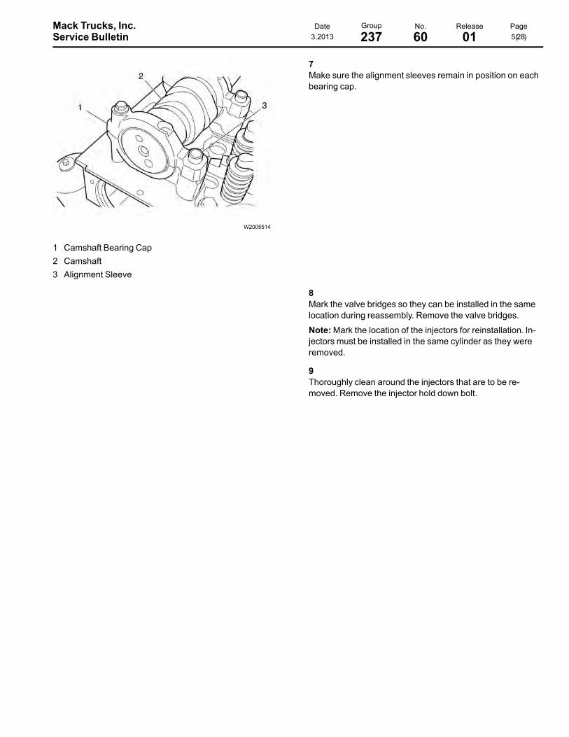
W2005514
1 Camshaft Bearing Cap2 Camshaft3 Alignment Sleeve
7Make sure the alignment sleeves remain in position on eachbearing cap.
8Mark the valve bridges so they can be installed in the samelocation during reassembly. Remove the valve bridges.
Note:Mark the location of the injectors for reinstallation. In-jectors must be installed in the same cylinder as they wereremoved.
9Thoroughly clean around the injectors that are to be re-moved. Remove the injector hold down bolt.
Mack Trucks, Inc. Date Group No. Release PageService Bulletin 3.2013 237 60 01 6(28)
W2005170
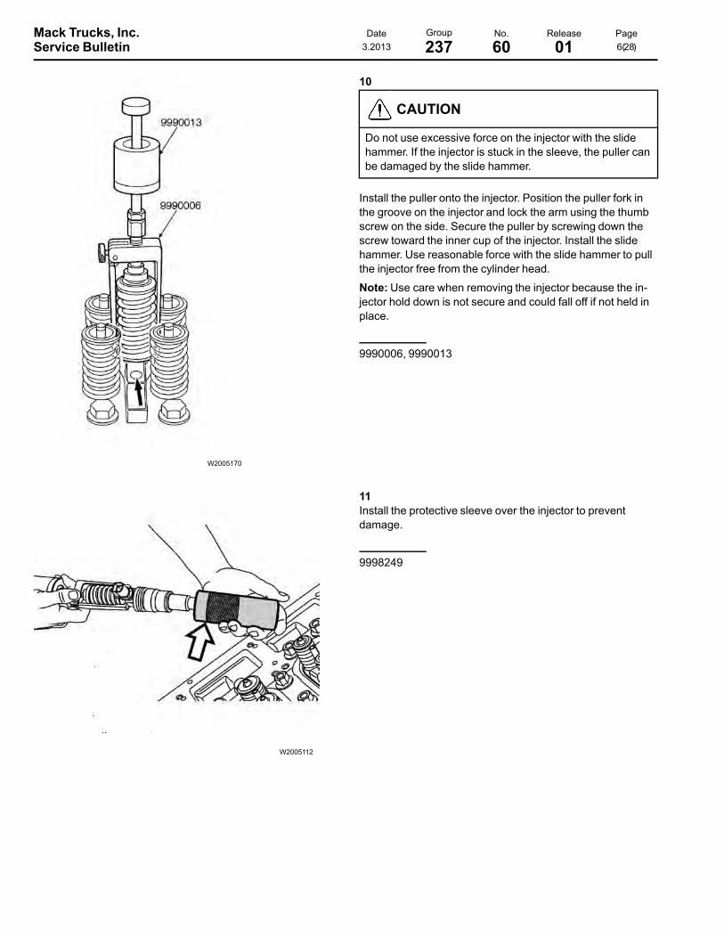
10
CAUTION
Do not use excessive force on the injector with the slidehammer. If the injector is stuck in the sleeve, the puller canbe damaged by the slide hammer.
Install the puller onto the injector. Position the puller fork inthe groove on the injector and lock the arm using the thumbscrew on the side. Secure the puller by screwing down thescrew toward the inner cup of the injector. Install the slidehammer. Use reasonable force with the slide hammer to pullthe injector free from the cylinder head.
Note:Use care when removing the injector because the in-jector hold down is not secure and could fall off if not held inplace.
9990006, 9990013
W2005112
11Install the protective sleeve over the injector to preventdamage.
9998249
Mack Trucks, Inc. Date Group No. Release PageService Bulletin 3.2013 237 60 01 7(28)
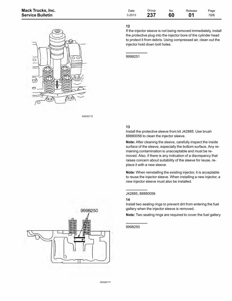
W2005172
12If the injector sleeve is not being removed immediately, installthe protective plug into the injector bore of the cylinder headto protect it from debris. Using compressed air, clean out theinjector hold down bolt holes.
9998251
13Install the protective sleeve from kit J42885. Use brush88880056 to clean the injector sleeve.
Note: After cleaning the sleeve, carefully inspect the insidesurface of the sleeve, especially the bottom surface. Any re-maining contamination is unacceptable and must be re-moved. Also, if there is any indication of a discrepancy thatraises concern about suitability of the sleeve for reuse, re-place it with a new sleeve.
Note:When reinstalling the existing injector, it is acceptableto reuse the injector sleeve. When installing a new injector, anew injector sleeve must also be installed.
J42885, 88880056
W2005171
14Install two sealing rings to prevent dirt from entering the fuelgallery when the injector sleeve is removed.
Note: Two sealing rings are required to cover the fuel gallery.
9998250

Mack Trucks, Inc. Date Group No. Release PageService Bulletin 3.2013 237 60 01 8(28)
15Install the flywheel turning tool. Turn the flywheel until the pis-ton is at its lowest position in the cylinder. Confirm the pistonis at the lowest position in the cylinder by using a 40 cm (16inch) piece of straight stiff wire in the injector hole of thecylinder.
Note: This is to ensure that the injector sleeve tapping tooldoes not damage the piston due to tool length.
Note: Ensure the turning tool is well greased before attempt-ing to turn the flywheel.
Note: If it is necessary to replace other injector sleeves, con-tinue the procedure on pairs of companion cylinders (1 and6, 2 and 5, 3 and 4). It is necessary to rotate the crankshaftand place each pair of companion cylinders at the lowest po-sition in the cylinder.
88800014, or 9996956
W2038611
16Insert the 8.3 mm forming tap into the tap handle until itstops. Make sure a flat on the tap is aligned with the upperset screw. Tighten upper set screw first, then tighten lowerset screw. Completely coat the forming tap with fresh, ex-treme pressure NLGI #2 grease or equivalent.
Note: Forming taps require extreme pressure grease due tothe cold working process used to form threads.
CAUTION
If the injector sleeve is not completely tapped through tothe opening of the tip, an end piece of the tip can break offand fall into the cylinder during removal. These types offailures are not covered by warranty.
88800289, 9998252
Mack Trucks, Inc. Date Group No. Release PageService Bulletin 3.2013 237 60 01 9(28)
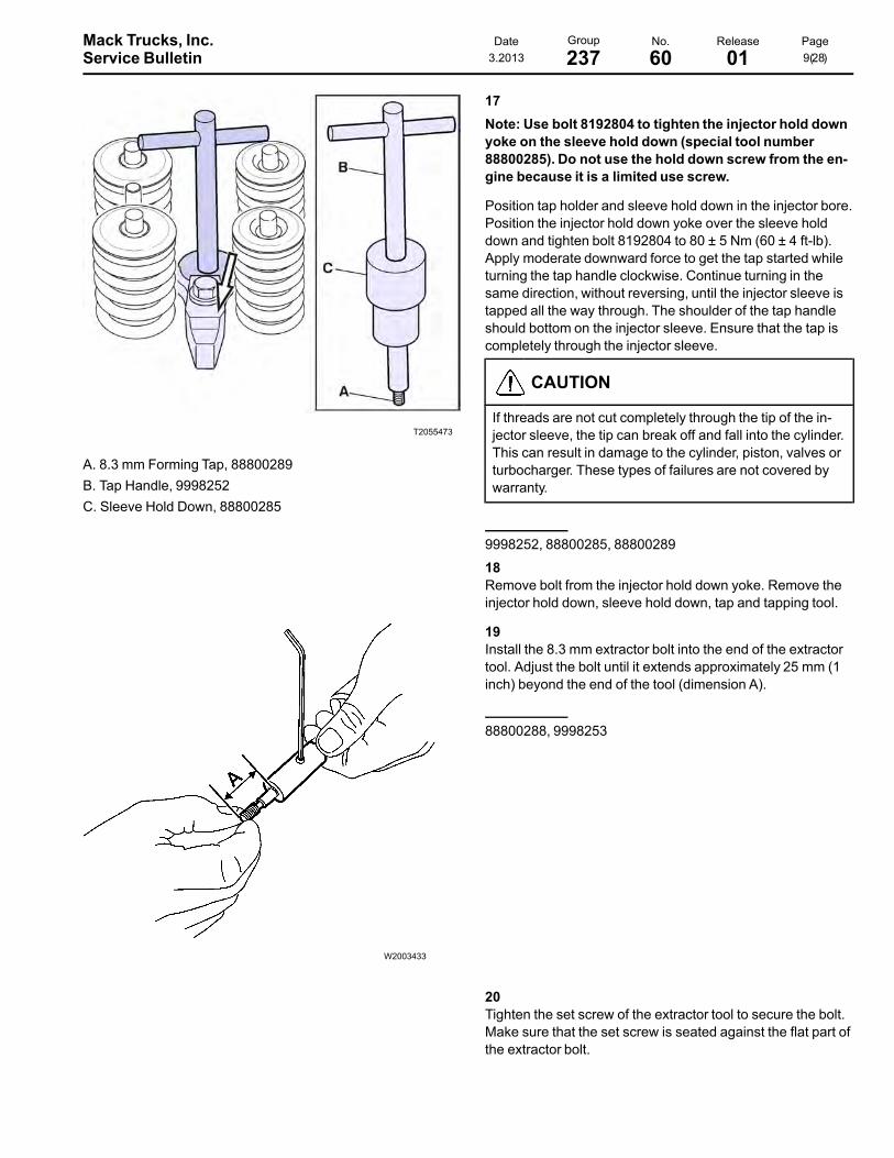
T2055473
A. 8.3 mm Forming Tap, 88800289B. Tap Handle, 9998252C. Sleeve Hold Down, 88800285
17Note: Use bolt 8192804 to tighten the injector hold downyoke on the sleeve hold down (special tool number88800285). Do not use the hold down screw from the en-gine because it is a limited use screw.
Position tap holder and sleeve hold down in the injector bore.Position the injector hold down yoke over the sleeve holddown and tighten bolt 8192804 to 80 ± 5 Nm (60 ± 4 ft-lb).Apply moderate downward force to get the tap started whileturning the tap handle clockwise. Continue turning in thesame direction, without reversing, until the injector sleeve istapped all the way through. The shoulder of the tap handleshould bottom on the injector sleeve. Ensure that the tap iscompletely through the injector sleeve.
CAUTION
If threads are not cut completely through the tip of the in-jector sleeve, the tip can break off and fall into the cylinder.This can result in damage to the cylinder, piston, valves orturbocharger. These types of failures are not covered bywarranty.
9998252, 88800285, 88800289
18Remove bolt from the injector hold down yoke. Remove theinjector hold down, sleeve hold down, tap and tapping tool.
W2003433
19Install the 8.3 mm extractor bolt into the end of the extractortool. Adjust the bolt until it extends approximately 25 mm (1inch) beyond the end of the tool (dimension A).
88800288, 9998253
20Tighten the set screw of the extractor tool to secure the bolt.Make sure that the set screw is seated against the flat part ofthe extractor bolt.

Mack Trucks, Inc. Date Group No. Release PageService Bulletin 3.2013 237 60 01 10(28)
W2005079
21
CAUTION
Make sure the extractor bolt is threaded completely intothe injector sleeve before attempting to remove it or the tipof the sleeve may break off as it is removed. This brokensleeve tip can seriously damage the piston, valves or tur-bocharger. These types of failures are not covered bywarranty.
Lubricate the threads of the pulling screw on the puller. Lubri-cate under the face of the nut. Place the extractor tool withthe bolt into the injector bore. Make sure the nut on the spin-dle is backed off so that the threaded end can be completelyinstalled through the injector sleeve tip. Hand tighten until thebolt bottoms out in the sleeve.
Note: If it is necessary to replace other injector sleeves, con-tinue the procedure on pairs of companion cylinders (1 and6, 2 and 5, 3 and 4). It is necessary to rotate the crankshaftand place each pair of companion cylinders at the lowest po-sition in the cylinder.
W2005442
22While holding the top of the tool stationary, turn the large nutclockwise to extract the injector sleeve.
Note:When the injector sleeve is removed, make sure thatthe extractor bolt is extended at least one thread beyond theinjector sleeve. If not, make sure that no part of the injectorsleeve has broken off and fallen into the cylinder.
CAUTION
Do not use air tools to remove injector sleeves, or damageto the injector bore can result.
9998253

Mack Trucks, Inc. Date Group No. Release PageService Bulletin 3.2013 237 60 01 11(28)
W2005171
23Remove the two sealing rings from the fuel passage. Usingthe chip vacuum, remove any remaining debris from the in-jector bore.
9998250, PT2900
24Install the injector bore sealing tool, J-42885-25, to protectthe fuel passage area and prevent debris from entering.
J-42885-25
W2006260
25Using the cleaning kit, J42885, clean the injector sleeve seatof the cylinder head.
Note: The injector bore sealing tool must be used to preventdirt from entering the fuel passage.
J42885-1, J42885-2, J42885-3, J42885-4, J-42885-25

Mack Trucks, Inc. Date Group No. Release PageService Bulletin 3.2013 237 60 01 12(28)
W2005616
26Using the brush, clean the cylinder head injector bore wallsfor the injector sleeve.
Note: The injector bore sealing tool must be used to preventdebris from entering the fuel passage.
J42885-6, J42885-25
W2005617
27Using the brush, clean the injector sleeve opening in the cyl-inder head.
Note: The injector bore sealing tool must be used to preventdebris from entering the fuel passage.
Note:When replacing the injector sleeves, it is important tocheck that the sleeve bore in the cylinder head is free fromany carbon deposits or other residue (i.e., pieces of O-ring,etc.) before installing a new injector sleeve. Repeat cleaningif necessary.
J42885-5, J-42885-25
28
WARNING
Do not attempt to blow away debris using compressed air.Doing so can result in eye injury.
Using the chip vacuum, remove all debris from the injectorsleeve bore.
PT2900
29Remove the injector bore sealing tool from the cylinder head.Using the chip vacuum, remove any remaining debris.
PT2900, J-42885-25
Mack Trucks, Inc. Date Group No. Release PageService Bulletin 3.2013 237 60 01 13(28)
30Ensure the piston is at the lowest position in the cylinder. Ifnot, use the flywheel turning tool to place the piston at its low-est position.
Note: This is to ensure that the sleeve installation tool doesnot damage the piston due to tool length.
88800014, 9996956
T2048540
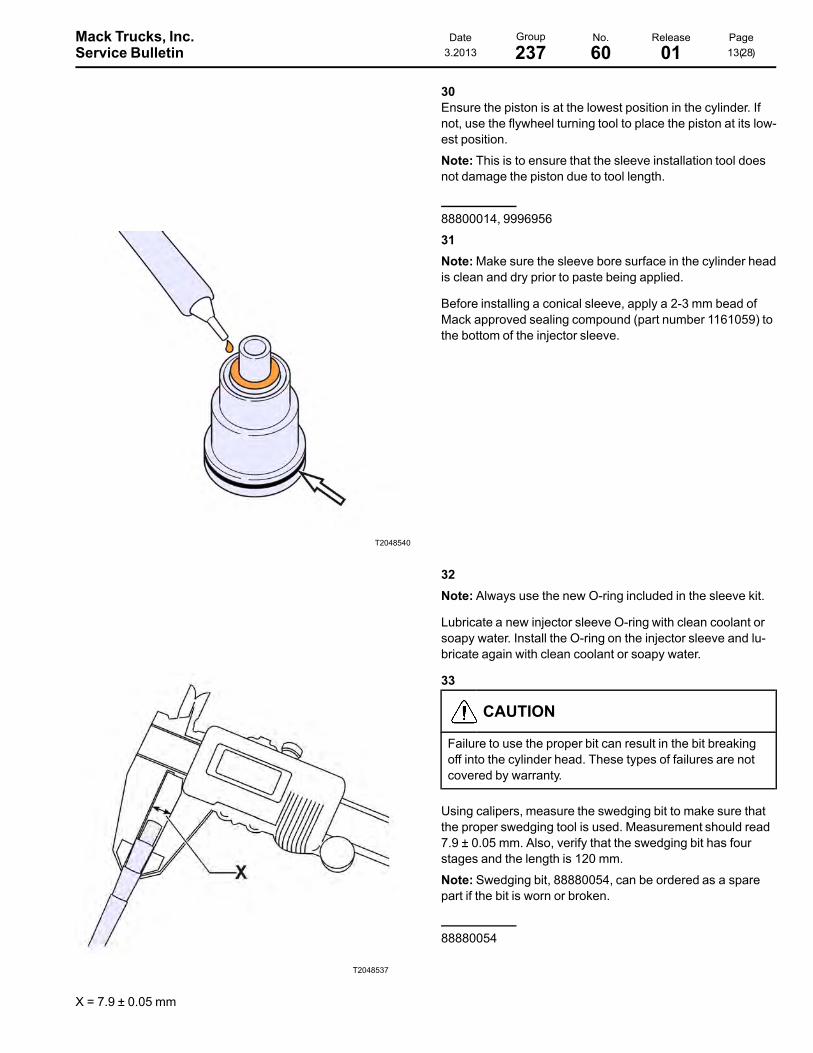
31Note:Make sure the sleeve bore surface in the cylinder headis clean and dry prior to paste being applied.
Before installing a conical sleeve, apply a 2-3 mm bead ofMack approved sealing compound (part number 1161059) tothe bottom of the injector sleeve.
32Note: Always use the new O-ring included in the sleeve kit.
Lubricate a new injector sleeve O-ring with clean coolant orsoapy water. Install the O-ring on the injector sleeve and lu-bricate again with clean coolant or soapy water.
T2048537
X = 7.9 ± 0.05 mm
33
CAUTION
Failure to use the proper bit can result in the bit breakingoff into the cylinder head. These types of failures are notcovered by warranty.
Using calipers, measure the swedging bit to make sure thatthe proper swedging tool is used. Measurement should read7.9 ± 0.05 mm. Also, verify that the swedging bit has fourstages and the length is 120 mm.
Note: Swedging bit, 88880054, can be ordered as a sparepart if the bit is worn or broken.
88880054
Mack Trucks, Inc. Date Group No. Release PageService Bulletin 3.2013 237 60 01 14(28)
W2080611
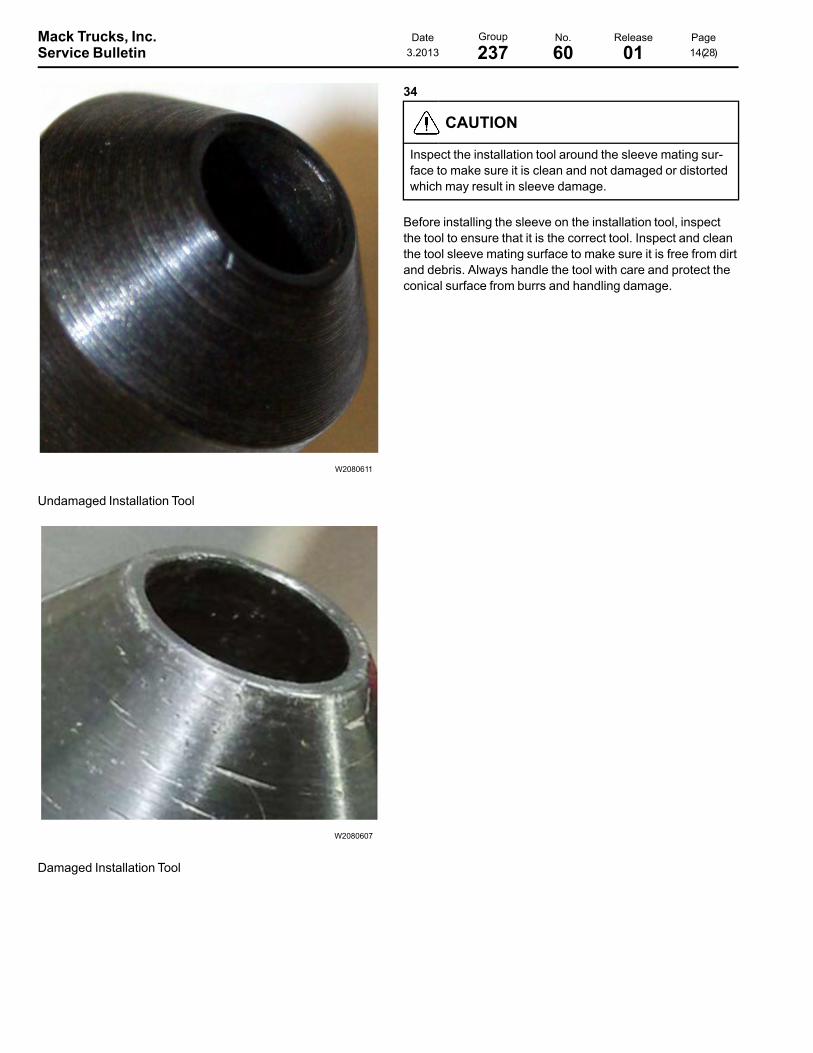
Undamaged Installation Tool
W2080607
Damaged Installation Tool
34
CAUTION
Inspect the installation tool around the sleeve mating sur-face to make sure it is clean and not damaged or distortedwhich may result in sleeve damage.
Before installing the sleeve on the installation tool, inspectthe tool to ensure that it is the correct tool. Inspect and cleanthe tool sleeve mating surface to make sure it is free from dirtand debris. Always handle the tool with care and protect theconical surface from burrs and handling damage.
Mack Trucks, Inc. Date Group No. Release PageService Bulletin 3.2013 237 60 01 15(28)
W2038612
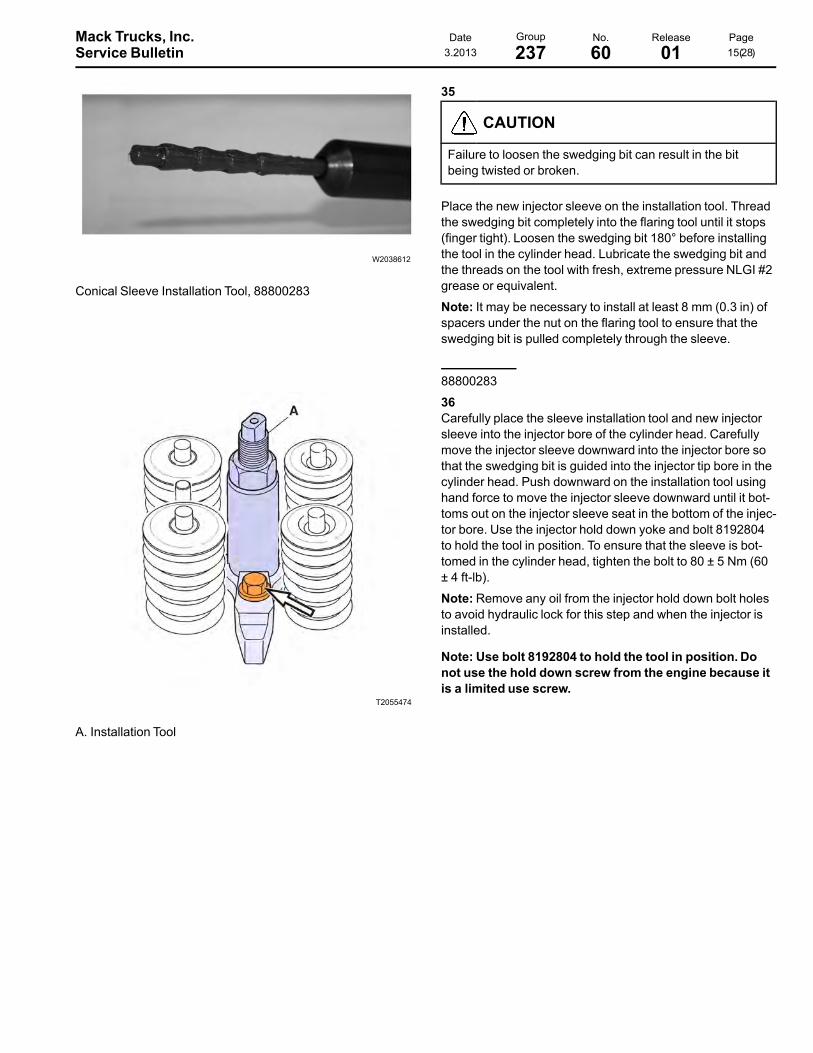
Conical Sleeve Installation Tool, 88800283
35
CAUTION
Failure to loosen the swedging bit can result in the bitbeing twisted or broken.
Place the new injector sleeve on the installation tool. Threadthe swedging bit completely into the flaring tool until it stops(finger tight). Loosen the swedging bit 180° before installingthe tool in the cylinder head. Lubricate the swedging bit andthe threads on the tool with fresh, extreme pressure NLGI #2grease or equivalent.
Note: It may be necessary to install at least 8 mm (0.3 in) ofspacers under the nut on the flaring tool to ensure that theswedging bit is pulled completely through the sleeve.
88800283
T2055474
A. Installation Tool
36Carefully place the sleeve installation tool and new injectorsleeve into the injector bore of the cylinder head. Carefullymove the injector sleeve downward into the injector bore sothat the swedging bit is guided into the injector tip bore in thecylinder head. Push downward on the installation tool usinghand force to move the injector sleeve downward until it bot-toms out on the injector sleeve seat in the bottom of the injec-tor bore. Use the injector hold down yoke and bolt 8192804to hold the tool in position. To ensure that the sleeve is bot-tomed in the cylinder head, tighten the bolt to 80 ± 5 Nm (60± 4 ft-lb).
Note:Remove any oil from the injector hold down bolt holesto avoid hydraulic lock for this step and when the injector isinstalled.
Note: Use bolt 8192804 to hold the tool in position. Donot use the hold down screw from the engine because itis a limited use screw.
Mack Trucks, Inc. Date Group No. Release PageService Bulletin 3.2013 237 60 01 16(28)
T2055477
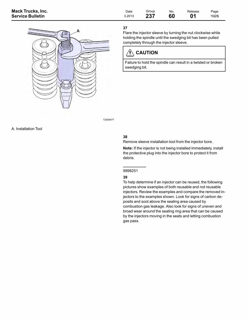
A. Installation Tool
37Flare the injector sleeve by turning the nut clockwise whileholding the spindle until the swedging bit has been pulledcompletely through the injector sleeve.
CAUTION
Failure to hold the spindle can result in a twisted or brokenswedging bit.
38Remove sleeve installation tool from the injector bore.
Note: If the injector is not being installed immediately, installthe protective plug into the injector bore to protect it fromdebris.
9998251
39To help determine if an injector can be reused, the followingpictures show examples of both reusable and not reusableinjectors. Review the examples and compare the removed in-jectors to the examples shown. Look for signs of carbon de-posits and soot above the sealing area caused bycombustion gas leakage. Also look for signs of uneven andbroad wear around the sealing ring area that can be causedby the injectors moving in the seats and letting combustiongas pass.
Mack Trucks, Inc. Date Group No. Release PageService Bulletin 3.2013 237 60 01 17(28)
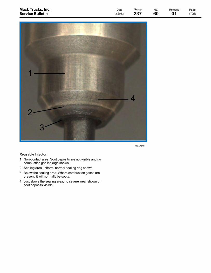
W2078381
Reusable Injector1 Non-contact area. Soot deposits are not visible and no
combustion gas leakage shown.2 Sealing area uniform, normal sealing ring shown.3 Below the sealing area. Where combustion gases are
present, it will normally be sooty.4 Just above the sealing area, no severe wear shown or
soot deposits visible.
Mack Trucks, Inc. Date Group No. Release PageService Bulletin 3.2013 237 60 01 18(28)
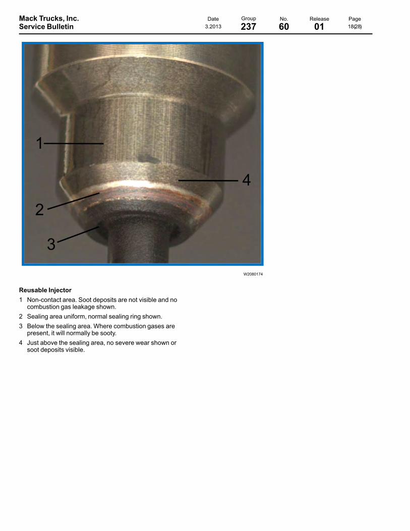
W2080174
Reusable Injector1 Non-contact area. Soot deposits are not visible and no
combustion gas leakage shown.2 Sealing area uniform, normal sealing ring shown.3 Below the sealing area. Where combustion gases are
present, it will normally be sooty.4 Just above the sealing area, no severe wear shown or
soot deposits visible.
Mack Trucks, Inc. Date Group No. Release PageService Bulletin 3.2013 237 60 01 19(28)
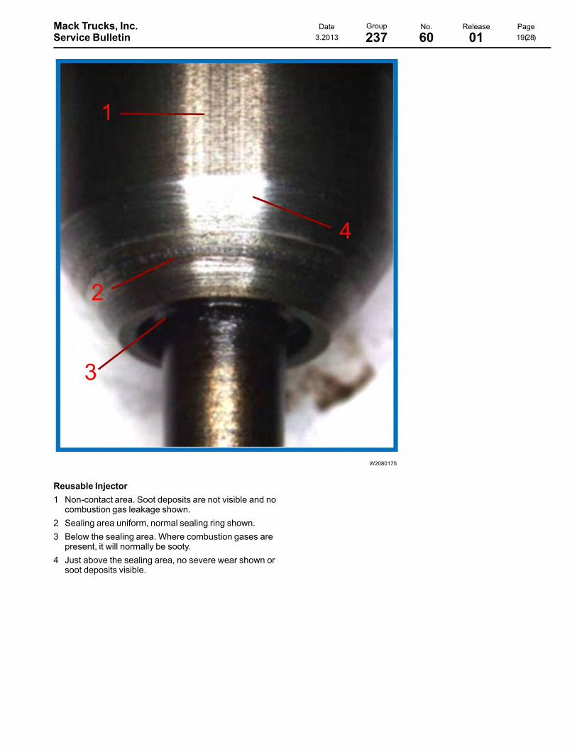
W2080175
Reusable Injector1 Non-contact area. Soot deposits are not visible and no
combustion gas leakage shown.2 Sealing area uniform, normal sealing ring shown.3 Below the sealing area. Where combustion gases are
present, it will normally be sooty.4 Just above the sealing area, no severe wear shown or
soot deposits visible.
Mack Trucks, Inc. Date Group No. Release PageService Bulletin 3.2013 237 60 01 20(28)
W2078380
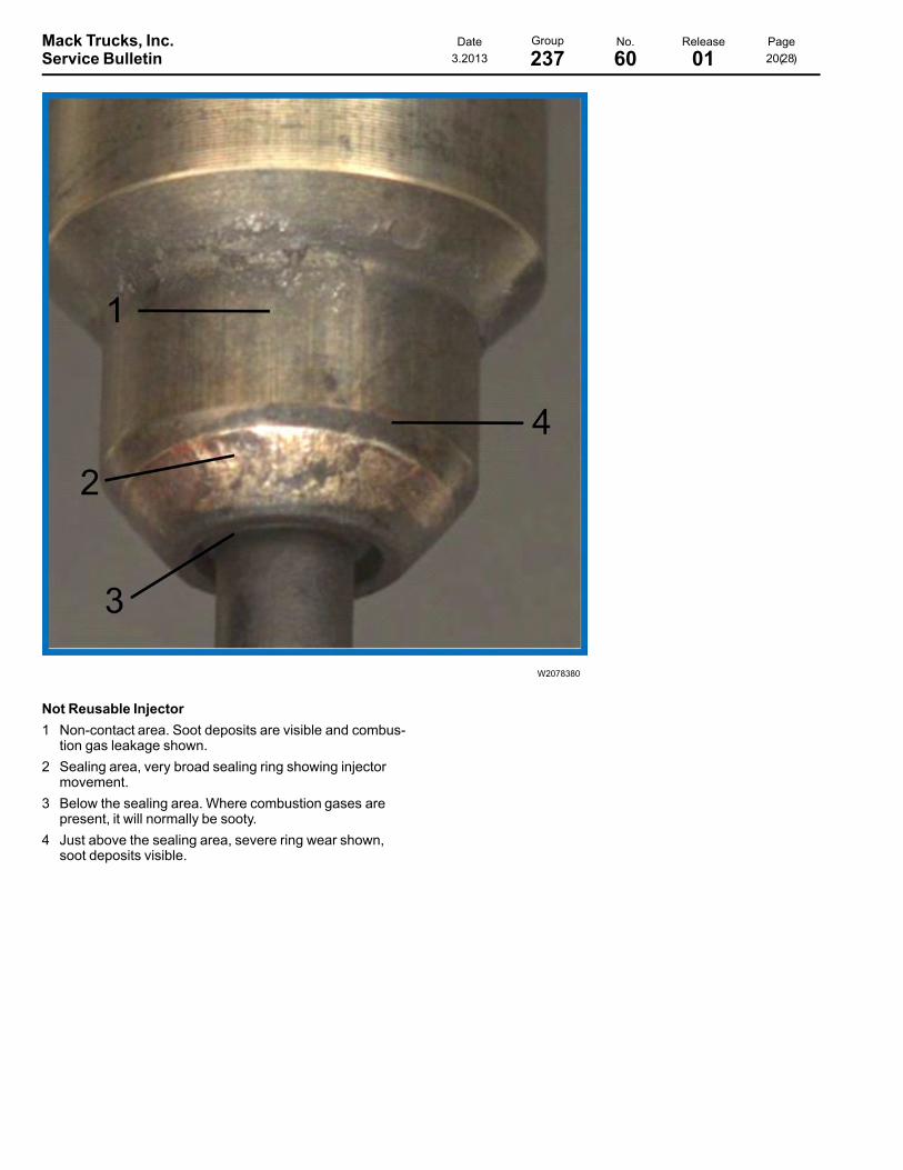
Not Reusable Injector1 Non-contact area. Soot deposits are visible and combus-
tion gas leakage shown.2 Sealing area, very broad sealing ring showing injector
movement.3 Below the sealing area. Where combustion gases are
present, it will normally be sooty.4 Just above the sealing area, severe ring wear shown,
soot deposits visible.

Mack Trucks, Inc. Date Group No. Release PageService Bulletin 3.2013 237 60 01 21(28)
W2080177
Not Reusable Injector1 Non-contact area. Soot deposits are visible and combus-
tion gas leakage shown.2 Sealing area, very broad sealing ring showing injector
movement.3 Below the sealing area. Where combustion gases are
present, it will normally be sooty.4 Just above the sealing area, severe ring wear shown,
soot deposits visible.

Mack Trucks, Inc. Date Group No. Release PageService Bulletin 3.2013 237 60 01 22(28)
W2080181
Not Reusable Injector1 Non-contact area. Soot deposits are visible and combus-
tion gas leakage shown.2 Sealing area, very broad sealing ring showing injector
movement.3 Below the sealing area. Where combustion gases are
present, it will normally be sooty.4 Just above the sealing area, severe ring wear shown,
soot deposits visible.

Mack Trucks, Inc. Date Group No. Release PageService Bulletin 3.2013 237 60 01 23(28)
W2080182
Not Reusable Injector1 Non-contact area. Soot deposits are visible and combus-
tion gas leakage shown.2 Sealing area, very broad sealing ring showing injector
movement.3 Below the sealing area. Where combustion gases are
present, it will normally be sooty.4 Just above the sealing area, severe ring wear shown,
soot deposits visible.
Mack Trucks, Inc. Date Group No. Release PageService Bulletin 3.2013 237 60 01 24(28)
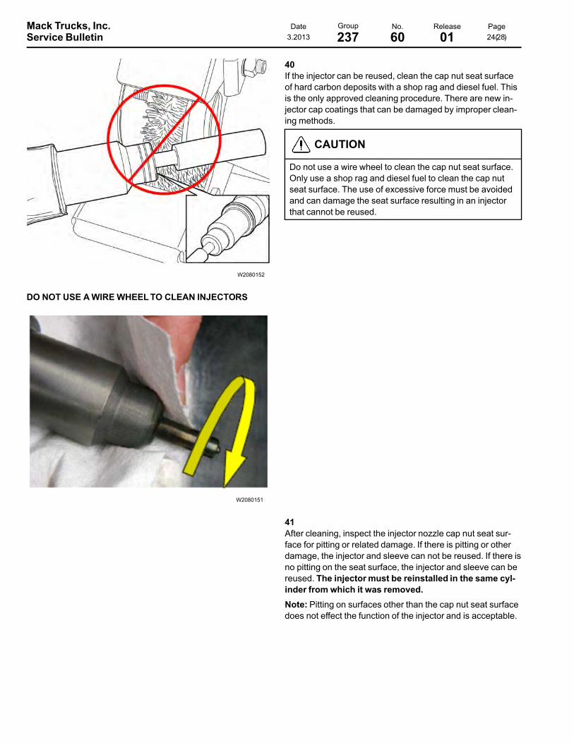
W2080152
DO NOT USE AWIREWHEELTO CLEAN INJECTORS
W2080151
40If the injector can be reused, clean the cap nut seat surfaceof hard carbon deposits with a shop rag and diesel fuel. Thisis the only approved cleaning procedure. There are new in-jector cap coatings that can be damaged by improper clean-ing methods.
CAUTION
Do not use a wire wheel to clean the cap nut seat surface.Only use a shop rag and diesel fuel to clean the cap nutseat surface. The use of excessive force must be avoidedand can damage the seat surface resulting in an injectorthat cannot be reused.
41After cleaning, inspect the injector nozzle cap nut seat sur-face for pitting or related damage. If there is pitting or otherdamage, the injector and sleeve can not be reused. If there isno pitting on the seat surface, the injector and sleeve can bereused. The injectormust be reinstalled in the same cyl-inder from which it was removed.Note: Pitting on surfaces other than the cap nut seat surfacedoes not effect the function of the injector and is acceptable.

Mack Trucks, Inc. Date Group No. Release PageService Bulletin 3.2013 237 60 01 25(28)
W2080149
1 Replace upper O-ring2 Remove and discard lower O-ring
42Before installing the new or reused injector, install a newupper O-ring (large diameter, violet) on the top injectorgroove only. If new injectors have O-rings installed on bothtop and bottom locations of the injector, remove the lower O-ring.
CAUTION
Do NOT replace the lower O-ring (small diameter, violet). Ithas been determined that the lower O-ring is not requiredfor conical injectors. The lower O-ringMUST be installedon flat injectors or damage to the engine may result.
43Lubricate the O-ring with clean engine oil.
44
CAUTION
Any oil which may have pooled in the bottom of the injectoryoke screw hole must be cleaned from the hole to avoidhydraulic lock when the screw is installed and tightened.Hydraulic lock would result in a lack of clamp load and/or acylinder head cracked at the screw hole.
When reusing a hold down screw, clean the screw before in-stallation. Apply a light coat of oil to the threads on the screwand to the underside of the screw head. Slip the injector holddown and screw onto the injector.

Mack Trucks, Inc. Date Group No. Release PageService Bulletin 3.2013 237 60 01 26(28)
W2075816
1 Use finger to apply paste to injector2 Graphite Paste
45
CAUTION
Do not get any hard particles on the injector sealing surfa-ces. Hard particles will prevent a good seal and damage toengine can result.
Note: Always wear gloves when applying graphite sealantpaste.
Use a finger tip to apply a thin layer of graphite sealant paste(part number 85134750) all around the injector cap nut cone.
46Center the injector between the valve springs and then pushdown on the injector using hand pressure to seat the O-ring.Clamp the injector in position with the injector hold down bytightening the injector hold down bolt. Tighten the injectorhold down bolt using the following five step procedure:1 Tighten 20 +5-0 Nm (15 +4-0 ft-lb).2 Tighten 180 ±5 degrees angle of tightening.3 Loosen the hold down bolt until torque is 10 to 15 Nm (7.0
to 11.0 ft-lb).
Note: This should be achieved by loosening with an angle of100-110 degrees. Do not completely loosen the bolt to pre-vent components from moving after the previous seatingprocess.
4 Tighten 20 +5-0 Nm (15 +4-0 ft-lb).5 Tighten 90 ±5 degrees angle of tightening.
Note: The injector hold down bolt can be used only five (5)times. After the initial installation, every additional applicationof the five step injector hold down bolt tightening process re-quires that a punch mark be applied to the head of the bolt.After four (4) punch marks have been accumulated, the boltcannot be reused again and must be replaced.

Mack Trucks, Inc. Date Group No. Release PageService Bulletin 3.2013 237 60 01 27(28)
W2080146
47When replacing injectors, the engine control module (ECM)must be programmedwith the new injector’s trim codes. Thecode is printed on top of the injector electrical connector. Theprogramming is performed using Tech Tool and is necessaryto ensure that engine timing and emission levels are correct.
Note:Due to the ECM self learning capability, it is necessaryto reset learned ECM parameters after servicing some en-gine related components. This allows the ECMU to learn thenew components behavior. After servicing is complete, per-form the “Learned Data Reset” using Tech Tool. This is lo-cated in the Function Group 1 menu.
Note: If reinstalling an injector into the same location, reprog-ramming is not required.
48Install the valve bridges onto the same cylinders as markedat disassembly. Lubricate the valve bridges and camshaftlobes with engine oil.
49Install the rocker shaft. Refer to Group 214 for serviceprocedures.
50Adjust all of the valves and injectors. Refer to Group 214 forservice procedures.
51Install the valve cover on the cylinder head. Refer to Group211 for procedure.
52Secure the fuel supply line fitting at the fuel filter housing(loosened earlier to drain fuel from the cylinder head). Cleanany fuel that remains around the fitting.
53Install all previously removed cables to the ground (negative)battery terminals.

Mack Trucks, Inc. Date Group No. Release PageService Bulletin 3.2013 237 60 01 28(28)
W2004191
54Use coolant extractor to fill the system with approved coolantper specifications.
2815–2V700, 85112740
T2021565
55Prime the fuel system by pumping the hand priming pump onthe fuel filter housing until resistance is felt indicating that thesystem is full of fuel.
56Start the engine and run until the engine clears and runswithout stumbling. This procedure may need to be repeatedonce or twice to get the fuel system completely free of air.
Note: If the engine does not start on the first attempt, primethe fuel system again, and refer to the previous step. Enginepriming may need to occur several times in order to get theengine to start.
57Allow the engine to run at low idle for about 5 minutes. Checkfor any fuel leaks and correct if necessary.
Note: The engine speed should not be increased as any airpockets can be forced into the cylinder head which can resultin the engine stopping.