revisiontransmittal caravan servicebulletin
TRANSCRIPT

Caravan SERVICE BULLETINCAB-34-03
REVISION TRANSMITTAL
This sheet transmits Revision 1 to CAB-34-03, which:A. Changes the serial effectivity of the bulletin.
B. Changes the software version upgrade from 767.23 to 767.25 throughout the document.
C. Adds the SAR and Heading Split fixes to the REASON statement.
D. Changes the part number of the data loader card from 010-00681-16 to 010-00681-18 throughout thedocument'
E. Changes the number of the data file from 006-B0767-23 to 006-B0767-25 in Table 3.
NOTE: This revision replaces the original issue of CAB-34-03 in its entirety.
REVISION COMPLIANCERECOMMENDED. Group A airplanes that have not incorporated the original issue of CAB-34-03 or have asoftware version earlier than 767.23 must complete this service bulletin in its entirety. Group A airplanes thathave incorporated the original issue of CAB-34-03 or have software version 767.23 or 767.24 must incorporateStep 2 of this service bulletin. Group B airplanes must incorporate Step 2 of this service bulletin.
LOG OF REVISIONS
Original Issue November 1, 2016
Revision 1 January 8, 2019
Original Issue - November 1, 2016 CAB-34-03Revision 1 - January 8, 2019 Page 1 of 1
Textron Aviation Customer Service, P.O. Box 7706, Wichita, KS 67277, U.S.A. 1-316-517-5800
COPYRIGHT © 2016


Caravan SERVICE BULLETINCAB-34-03
TITLENAVIGATION - GARMIN G1000 SYSTEM SOFTWARE UPGRADE TO VERSION 0767.25
EFFECTIVITYGroup A Airplanes
MODEL SERIAL NUMBERS208B 208B5000 thru 208B5366
Group B Airplanes
MODEL SERIAL NUMBERS208 20800416, 20800500 thru 20800594
208B 208B1190, 208B1216, 208B2000 thru 208B4999
REASONThis version 0767.25 software service bulletin provides an upgrade from version 0767.13 (or later)that includes the following changes:
• GPS/WAAS Updates: GPS/WAAS software has been updated to satisfy new requirements associatedwith RTCA/DO-229D.
• User Defined Holding Patterns: This new feature is designed to allow the pilot to define his ownholding patterns in the flight plan. This feature does not remove the system's capability to fly existingpre-defined holding patterns.
• Geo-Reference Garmin Flight Charts: This update will allow the default electronic departure chartprovided by Garmin (FliteCharts) to also provide a GPS derived aircraft ownership overlay above thecurrently selected chart similar to Chartview. This feature only applies to Approach Charts that are to scale.
• Localizer Performance (LP) Approach Support: This update adds software support to display andfly Localizer Performance (LP) approaches on the G1000 system.
• Radius to Fix (RF) leg Support: An RF or Radius to Fix leg defines a circle of specified radius enablingan aircraft to fly a precise curved flight path relative to the surface of the earth. Phase 14 software updateadds software support for Radius to Fix legs (RF legs) functionality.
• LNAV/VNAV and LNAV+V Approaches: Previously, CDI (Course Deviation Indicator)/HSI (HorizontalSituation Indicator) scaling was incorrect on a limited number of LNAV/VNAV and LNAV+V approaches.As a result Garmin removed the capability of selecting these affected approaches starting Databasecycles 1013 and 1103. Phase 14 restores these approaches that were suppressed in compliance withService Advisory 1047.
• ADS-B Out Support: Supports ADS-B Out functionality when installed by Caravan service bulletinCAB-34-04.
• Prist Free Capability: Hardware, wiring and software to support the ability not to use Prist anti-icingadditive in the fuel when operating in temperatures of 5 degrees Celsius or lower.
• Heading Split: Fixes an issue where heading splits during flight cause sensor miscompares betweenheadings displayed from the AHRS 1 and AHRS 2.
• SAR: Fixes an issues with circular SAR patterns where the Direct-To that the system creates to enterthe SAR pattern starts at the wrong location. This causes an undesired turn onto the pattern and anincomplete orbit.
DESCRIPTIONThis service bulletin provides parts and instructions to upgrade the G1000 software to version 0767.25from version 0767.13 (or later). Group A airplanes that have not incorporated the original issue of
Original Issue - November 1, 2016 CAB-34-03Revision 1 - January 8, 2019 Page 1 of 14
Textron Aviation Customer Service, P.O. Box 7706, Wichita, KS 67277, U.S.A. 1-316-517-5800This document contains technical data and is subject to U.S. export regulations. This information has been exported from the United States
in accordance with export administration regulations. Diversion contrary to U.S. law is prohibited. ECCN: 9E991
COPYRIGHT © 2016

CAB-34-03Page 2 Revision 1 - January 8, 2019
Caravan SERVICE BULLETINCAB-34-03
CAB-34-03 or have a software version earlier than 767.23 must complete this service bulletin in itsentirety. Group A airplanes that have incorporated the original issue of CAB-34-03 or have softwareversion 767.23 or 767.24 must incorporate Step 2 of this service bulletin. Group B airplanes mustincorporate Step 2 of this service bulletin.
COMPLIANCERECOMMENDED. This service bulletin should be accomplished within the next 1200 flight hours or 24months, whichever occurs first.
A service document published by Textron Aviation may be recorded as completed in an aircraft logonly when the following requirements are satisfied:
1) The mechanic must complete all of the instructions in the service document, including the intenttherein.
2) The mechanic must correctly use and install all applicable parts supplied with the servicedocument kit. Only with written authorization from Textron Aviation can substitute parts or rebuiltparts be used to replace new parts.
3) The mechanic or airplane owner must use the technical data in the service document only asapproved and published.
4) The mechanic or airplane owner must apply the information in the service document only toaircraft serial numbers identified in the Effectivity section of the document.
5) The mechanic or airplane owner must use maintenance practices that are identified as acceptablestandard practices in the aviation industry and governmental regulations.
No individual or corporate organization other than Textron Aviation is authorized to make or apply anychanges to a Textron Aviation-issued service document or flight manual supplement without prior writtenconsent from Textron Aviation.
Textron Aviation is not responsible for the quality of maintenance performed to comply with this document,unless the maintenance is accomplished at a Textron Aviation-owned Service Center.
APPROVALCessna received FAA approval for the technical data in this publication that changes the airplane typedesign.
FLIGHT CREW OPERATIONSRefer to the attached Flight Crew Operations Summary.
CONSUMABLE MATERIALYou must use the consumable materials that follow, or their equivalent, to complete this service bulletin.
NAME NUMBER MANUFACTURER USESealant U000117 Textron Aviation
Textron Aviation Parts Distribution5800 East Pawnee, PO Box 1521Wichita, KS 67218
To refill conduit
TOOLINGDMC AFM8 Crimping Tool (or equivalent);
K42 Adapter or equivalent for 22 gauge wire.
WEIGHT AND BALANCE INFORMATIONNegligible

Caravan SERVICE BULLETINCAB-34-03
REFERENCESCessna Model 208 Maintenance Manual.
The following document is available for download from www.txtavsupport.com and Cessna AuthorizedService Facilities can view it at www.garmin.com:
Garmin G1000 Caravan Line Maintenance Manual, Part Number 190-00869-00, Rev. G or later.
NOTE: Make sure all publications used are complete and current. Refer to www.txtavsupport.com.
PUBLICATIONS AFFECTEDCessna Model 208 Illustrated Parts Catalog;
Pilot's Operating Handbook and FAA approved Airplane Flight Manual.
ACCOMPLISHMENT INSTRUCTIONSNOTE: Obtain the applicable POH supplements listed in the Flight Crew Operations Summary of this service
bulletin before starting the modification.
NOTE: PT6A-140 Engines that are before and include Serial No. PCE-VA0084 accomplish Pratt & Whitneyservice bulletin 1724 prior to wiring modification.
NOTE: PT6A-140 Engines that are before and include Serial No. PCE-VA0210 accomplish Pratt & Whitneyservice bulletin 1736 prior to wiring modification.
NOTE: Addition of wiring is recommended to be accomplished by an avionics facility or technician withexperience in fabricating 22 gauge wiring harnesses.
1. Group A airplanes with FAST ETM installed that have not incorporated the original issueof CAB-34-03 or have a software version earlier than 767.23: Contact DPHM support [email protected] to request the FAST ETM Rev. C config file. Provide airframe, engine, and FASTETM serial numbers. Allow 48 hours for response. Do not install these files before step 3.
A. Prepare the airplane for maintenance.
(1) Make sure that the airplane is electrically grounded.
(2) Make sure that all switches are in the OFF/NORM position.
(3) Place a "Maintenance in Progress" warning tag in the cockpit of the aircraft.
B. Accomplish Pratt & Whitney service bulletins 1736 and 1724, as applicable.
C. (Refer to Figure 1, Sheet 1 and 2.) Add wiring from GEA71 to Fuel Temp Probe as follows:
(1) Remove pilot seat. (Refer to Cessna Model 208 Maintenance Manual, Chapter 25, FlightCompartment - Maintenance Practices.)
(2) Remove PFD1, MFD, and GEA71.
(3) (Refer to Figure 1, Sheet 1.) Remove GEA rack backplate from rack, remove GEA matingconnectors from the backplate and do the wiring modification on Connector ReferenceDesignator PI001 (Garmin Reference Designator 1P701).
(4) Route a wire to the left side of the bulkhead.
(5) Remove left hand engine side cowling.
(6) (Refer to Figure 1, Sheet 2.) Remove the firewall fuselage conduit, which is next to the standbyalternator box.
(7) Remove tie straps and sealer from inside of the conduit feed-through.
(8) Route wiring from left hand side of the bulkhead through the conduit to the left hand engineusing the existing wire bundle. Remove cap from fuel temp probe.
CAB-34-03Revision 1 - January 8, 2019 Page 3

CAB-34-03Page 4 Revision 1 - January 8, 2019
Caravan SERVICE BULLETINCAB-34-03
(9) Terminate the wires and connect to the fuel temp probe.
(10) Refill U000117 sealant in the conduit and reinstall the conduit. Replace any tie straps onthe conduit.
NOTE: Allow sealant appropriate time to cure.
(11) Reinstall PFD1, MFD and GEA71.
(12) Reinstall pilot seat. (Refer to Cessna Model 208 Maintenance Manual, Chapter 25, FlightCompartment - Maintenance Practices.)
2. Group A and Group B airplanes accomplish the following:
NOTE: If the system software or configuration fails to upload correctly during accomplishment ofthis service bulletin, do the upload again. Do not try to upload more than five times. If thesystem does not upload after the fifth attempt, refer to the Garmin Line Maintenance Manual,190-00869-00 Revision G or later, Appendix B.10 Software / Configuration Troubleshooting. If thesystem still does not upload, contact Cessna Customer Care: Telephone 316-517-5800 or FAX316-517-7271. Do not cancel a software or configuration upload that is in progress. Letthe system either successfully load or fail.
NOTE: If the alert chime comes on at any time during the accomplishment of this service bulletin, you cango to the Alert Configuration page in the GDU page group, push the soft key directly below theACK, and this should make the chime stop. You can also accomplish this on the MFD screen ifyou need to make the chime stop during a software load.
NOTE: Group A airplanes prepared for maintenance in step 1.A. These airplanes should go tostep 2.B.
A. Prepare the airplane for maintenance.
(1) Make sure that the airplane is electrically grounded.
(2) Make sure that all switches are in the OFF/NORM position.
(3) Place a "Maintenance in Progress" warning tag in the cockpit of the aircraft.
B. Do the pre-loading procedure as follows:
(1) Make sure that all of the necessary circuit breakers are pushed in for normal mode startup ofthe G1000 System.
(2) Make sure that the EXTERNAL POWER switch is set to BUS and the AVIONICS 1 and2 switches are set to ON.
(3) Let the system Power on in normal mode.
(4) Disengage the PFD1 circuit breaker.
(5) Push and hold the ENT key on the PFD1 and engage the PFD1 circuit breaker.
(6) Release the ENT key when the message INITIALIZING SYSTEM shows on the PFD1.
(7) Turn the large FMS knob on the PFD1 to go to the GDU group.
(8) Turn the small FMS knob to go to the AIRFRAME CONFIGURATION page.
(9) Push the small FMS knob on the PFD1 to start the cursor and then turn the large FMS knob toscroll to the AIRFRAME box.
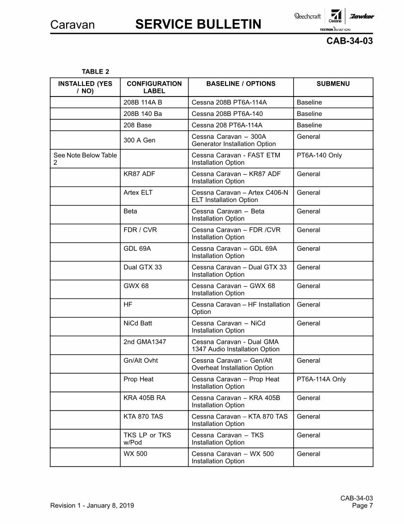
(10) Turn the small FMS knob on the PFD1 to scroll through the list of options shown and useTable 2 to make a list of the options installed on the airplane. This list is necessary to do theconfiguration procedures in Step 2.E.
(11) Disengage the PFD1, PFD2, and MFD circuit breakers.
(12) Make sure that you have TERRAIN DATA CARD to re-load the TAWS configuration.

Caravan SERVICE BULLETINCAB-34-03
C. Load the GDU (PFD1, PFD2, and MFD) Software as follows:
(1) Remove the GDU Supplemental Database (SD) Cards from the bottom slot of the PFD1,PFD2, and MFD displays and identify each as PFD1, PFD2, or MFD.
(2) Keep the cards in a safe place for later installation.
(3) Install the 010-00681-18 G1000 Software Loader Card into the upper slot of the PFD2 display.
(4) Push and hold the ENT key on the PFD2 while you engage the PFD2 circuit breaker.
(5) Release the ENT key when the message INITIALIZING SYSTEM shows on the PFD2.
(6) Push the YES soft key to upload GDU system files when the message DO YOU WANT TOUPDATE SYSTEM FILES?shows.
(7) Push any key when the prompt PRESS ANY KEY TO CONTINUE shows on the PFD2.
(8) The software installation to the PFD2 is done when the screen goes into the configurationmode.
(9) Remove the software loader card from the PFD2 slot but do not remove power from the display.
(10) Put the software loader card into the MFD upper SD Card slot.
(11) Push and hold the ENT key on the MFD and engage the MFD circuit breaker.
(12) Release the ENT key when the message INITIALIZING SYSTEM shows on the MFD.
(13) Do steps 2.C.6 thru 2.C.9 again for the MFD.
(14) After the loading is complete, remove the SD Card from the MFD slot but do not removepower from the display.
(15) Put the software loader card into the PFD1 upper SD Card slot.
(16) Push and hold the ENT key on the PFD1 and engage the PFD1 circuit breaker.
(17) Release the ENT key when the message INITIALIZING SYSTEM shows on the PFD1.
(18) Do steps 2.C.6 thru 2.C.9 again for the PFD1.
(19) The PFD1 will start in the configuration mode when you complete the update. Do not removepower from the PFD1. Keep the software loader card in the upper slot of the PFD1.
D. Do the initial G1000 software and configuration upload:
(1) Turn the large FMS knob on the PFD1 to go to the SYSTEM group and then turn the smallFMS knob to go to the SYSTEM UPLOAD page.
(2) Push the small FMS knob on the PFD1 to start the cursor.
(3) In the "Group" field, select "Caravan Baseline Loads." In the "Item" field, select the baselineload from the table below that matches what was recorded in Table 2.
Table 1
ItemCessna 208B PT6A-114A - Baseline Configuration
Cessna 208B PT6A-140 - Baseline Configuration
Cessna 208 PT6A-114A - Baseline Configuration
(4) Push the LOAD soft key to install the software and configuration settings.
NOTE: The software included in the 010-00681-18 SD Card will automatically determine allother files that must be loaded.
CAB-34-03Revision 1 - January 8, 2019 Page 5

CAB-34-03Page 6 Revision 1 - January 8, 2019
Caravan SERVICE BULLETINCAB-34-03
(5) Monitor the upload status. When the Upload Complete message is shown, push the ENTkey to select OK.
NOTE: This can take up to 60 minutes.
(6) If a software or configuration upload shows a failure, the software upload process will stop,and you must do the software upload procedure again. Do steps 2.D.4 thru 2.D.6 again asnecessary up to a total of five times until you successfully complete the configuration upload. Ifafter five times the software configuration fails, do an inspection of and correct the hardwarefailures and start the configuration upload again. (Refer to Garmin Line Maintenance Manual,190-00869-00 Revision G or latest revision.)
(7) It is safe to cycle the airplane power if the upload has stopped.
E. Use the list of options you made in TABLE 2 and load the applicable options installed on the airplaneas follows:
NOTE: This can take several minutes for each option.
WARNING: Do not configure an option that is not installed on the airplane.
(1) Turn the large FMS knob counterclockwise to go to the GROUP file menu.
(2) Turn the small FMS knob clockwise to expand the GROUP file and pull down menu andhighlight INSTALLATION OPTIONS - SUBMENU group as defined by the related SUBMENUColumn entry for each installation option listed in Table 2.
(3) Push the ENT key.
(4) Turn the large FMS knob clockwise to go to the ITEM menu (if you are not already at theITEM menu).
(5) Turn the small FMS knob to expand the ITEM pull down menu field and highlight one of theCessna Caravan options from TABLE 2 that is applicable to your airplane. Highlight only thoseoptions from Table 2 that are installed on your airplane.
NOTE: Options found in the ITEM pull down menu that are not listed in Table 2 are notapplicable to current field airplanes.
(6) Push the ENT key.
(7) Push the LOAD soft key to install the software.
(8) Monitor the upload status. When the Upload Complete message is shown, push the ENTkey to select OK.
(9) If a software option upload shows a failure, the software upload process will stop, and you mustdo the software upload procedure again. Do Steps 2.E.7 thru 2.E.9 again as necessary for thatoption up to a total of five times until you successfully complete the configuration upload. Ifafter five times the software configuration fails, do an inspection of and correct the hardwarefaults and start the software option upload again. (Refer to Garmin Line Maintenance Manual,190-00869-00 Revision G or latest revision.)
(10) Do Steps 2.E.1 thru 2.E.9 again until all applicable software option uploads are complete.
(11) Push the small FMS knob to stop the cursor.
(12) Push the UPDT CFG and then the ENT keys to select YES to update the PFD1 configurationmodule.
(13) Push the ENT key to select OK after you see the UPDATE CONFIG COMPLETE message.
Caravan SERVICE BULLETINCAB-34-03
TABLE 2
INSTALLED (YES/ NO)
CONFIGURATIONLABEL
BASELINE / OPTIONS SUBMENU
208B 114A B Cessna 208B PT6A-114A Baseline
208B 140 Ba Cessna 208B PT6A-140 Baseline
208 Base Cessna 208 PT6A-114A Baseline
300 A Gen Cessna Caravan – 300AGenerator Installation Option
General
See Note Below Table2
Cessna Caravan - FAST ETMInstallation Option
PT6A-140 Only
KR87 ADF Cessna Caravan – KR87 ADFInstallation Option
General
Artex ELT Cessna Caravan – Artex C406-NELT Installation Option
General
Beta Cessna Caravan – BetaInstallation Option
General
FDR / CVR Cessna Caravan – FDR /CVRInstallation Option
General
GDL 69A Cessna Caravan – GDL 69AInstallation Option
General
Dual GTX 33 Cessna Caravan – Dual GTX 33Installation Option
General
GWX 68 Cessna Caravan – GWX 68Installation Option
General
HF Cessna Caravan – HF InstallationOption
General
NiCd Batt Cessna Caravan – NiCdInstallation Option
General
2nd GMA1347 Cessna Caravan - Dual GMA1347 Audio Installation Option
Gn/Alt Ovht Cessna Caravan – Gen/AltOverheat Installation Option
General
Prop Heat Cessna Caravan – Prop HeatInstallation Option
PT6A-114A Only
KRA 405B RA Cessna Caravan – KRA 405BInstallation Option
General
KTA 870 TAS Cessna Caravan – KTA 870 TASInstallation Option
General
TKS LP or TKSw/Pod
Cessna Caravan – TKSInstallation Option
General
WX 500 Cessna Caravan – WX 500Installation Option
General
CAB-34-03Revision 1 - January 8, 2019 Page 7

CAB-34-03Page 8 Revision 1 - January 8, 2019
Caravan SERVICE BULLETINCAB-34-03
INSTALLED (YES/ NO)
CONFIGURATIONLABEL
BASELINE / OPTIONS SUBMENU
Com3 w/GMA2 Cessna Caravan - Com3 w/2ndAudio Installation Option
General
ADF w/GMA2 Cessna Caravan - KR87 ADFw/2nd Audio Installation Option
General
NOTE: FAST ETM option is loaded for aircraft serials 208B5000 through 208B5120 that havecomplied with CAB-77-01. In addition, FAST ETM option is loaded for serials 208B5121through 208B5366.
F. Do the transponder configuration as follows:
(1) Using the FMS knobs, go the "Aircraft Configuration" page in the "System" group.
(2) Configure the aircraft registration number and the VFR code in the "Aircraft Configuration"window if they are not already present. Enter the ICAO address if this field has notautomatically populated.
(3) Press the "SET GTX1" softkey and select "OK." The box after GTX1 should now have agreen check.
(4) (Airplanes equipped with dual transponders) Press the "SET GTX2" softkey and select "OK."The box after GTX2 should now have a green check.
G. Do the manifest configuration verification as follows:
(1) On the PFD1, turn the large FMS knob to go to the SYSTEM group. Turn the small FMS knobto go to the MANIFEST CONFIGURATION page.
(2) (Refer to TABLE 3.) Make sure that the data file and file version shown in TABLE 3 are shownin the SYSTEM field window.
TABLE 3
DATA FILE FILE VERSION006-B0767-25 0767.25
(3) Put the AVIONICS 1 and 2 switches to the OFF position and remove the software SD loadercard from the top slot of the PFD1 to PFD2.
(4) Install the three GDU Supplement Database SD Cards into the bottom slots of the PFD1,PFD2, and MFD from which you removed them.
(5) Pull PFD1 and MFD circuit breakers. Set avionics switches to the ON position.
(6) Put the AVIONICS 1 and 2 switches to the ON position and let the system power on in normalmode.
(7) On PFD2, when "DO YOU WANT TO UPDATE SYSTEM FILES" appears, select "NO."
(8) When "DO YOU WANT TO UPDATE SPLASH SCREEN FILES" appears, select "YES."
(9) When the splashscreen file has completed, PFD2 will advance to the normal PFD screen.Remove SD card from PFD2 and insert into top slot of MFD. Push in MFD breaker.
(10) On the MFD. when "DO YOU WANT TO UPDATE SYSTEM FILES" appears, select "NO."
(11) On the MFD, "DO YOU WANT TO UPDATE SPLASH SCREEN FILES" appears, select "YES."
(12) When the splashscreen file update has completed, the MFD will advance to the normal MFDsplashscreen page. Remove SD card from MFD and insert into top slot of PFD1. Push inPFD1 breaker.

Caravan SERVICE BULLETINCAB-34-03
(13) Repeat steps 2.G.7 and 2.G.8 for PFD1.
(14) When the splashscreen file update has completed, PFD1 will advance to the normal PFDscreen. Make sure that no unexpected G1000 system messages, alerts, annunciations, or RedX's are shown on PFD1, PFD2, or the MFD on the AUX-SYSTEM STATUS page.
(15) Remove the SD loader card and stow the software SD loader card in the blue airplane sleevefound in the airplane POH.
(16) Look at TABLE 4.
(a) If one or more options shown in TABLE 4 were ordered at the factory or installed byservice bulletin, go to Step 2.H.
(b) If no options shown in TABLE 4 were previously installed at the factory, go to Step 2.I.
H. Do the procedure that follows to re-enable the options from TABLE 4 that the owner had previouslyordered.
TABLE 4: OPTIONS TO ENABLE
TAWS Configuration (010-00330-51 TAWS Unlock Card)
Jepp Chartview Configuration (010-00330-50 Chartview Unlock Card)
Enhanced SAR Configuration (010-00330-59 Enhanced SAR Unlock Card)
Synthetic Vision Technology (SVT) Configuration (010-00330-55 SVS Unlock Card)
NOTE: An SD unlock card for each of the options shown in this table was delivered with the airplane asloose equipment or purchased from Cessna Service Parts and Programs and is necessary to enablethe option.
(1) Disengage the PFD1, PFD2, and MFD circuit breakers.
(2) Remove the GDU Supplemental Database SD Cards from the bottom slot of the PFD1, PFD2,and MFD displays as applicable.
(3) Push and hold the ENT key on the PFD2 while you engage the PFD2 circuit breaker.
(4) Release the ENT key when the message INITIALIZING SYSTEM shows on the PFD2.
(5) Push and hold the ENT key on the MFD and engage the MFD circuit breaker.
(6) Release the ENT key when the message INITIALIZING SYSTEM shows on the MFD.
(7) Put the 010-00330-51 TAWS Unlock Card (010-00330-50 Chartview Unlock Card,010-00330-55 SVS Unlock Card), and 010-00330-59 Enhanced SAR Unlock Card, into theupper slot of the PFD1 display.
(8) Push and hold the ENT key on the PFD1 and engage the PFD1 circuit breaker.
(9) Release the ENT key when the message INITIALIZING SYSTEM shows on the PFD1.
(10) On the PFD1, turn the large FMS knob to go to the SYSTEM group and turn the small FMSknob to go to the SYSTEM UPLOAD page.
(11) Push the small FMS knob to activate the cursor.
(12) Turn the small FMS knob to expand the drop down menu and highlight CONFIGURATIONFILES.
(13) Push the ENT key.
(14) Turn the small FMS knob to expand the drop down menu. Highlight ENABLE TAWS (ENABLECHARTVIEW or ENABLE SVS DUAL PFD) and Enhanced SAR Configuration.
(15) Push the ENT key.
CAB-34-03Revision 1 - January 8, 2019 Page 9
CAB-34-03Page 10 Revision 1 - January 8, 2019
Caravan SERVICE BULLETINCAB-34-03
(16) Push the LOAD soft key to start the upload.
(17) Push the ENT key after you see the UPLOAD COMPLETE message.
(18) Push the UPDT CFG and then the ENT keys to select YES to update the PFD1 configurationmodule.
(19) Push the ENT key to select OK after you see the UPDATE CONFIG COMPLETE message.
(20) If you will enable more options from TABLE 4, disengage the PFD1 circuit breaker and doSteps 2.H.7 thru 2.H.20 for each of the remaining options as necessary.
(21) If a software option upload shows a failure, the software upload process will stop, and you mustdo the software upload procedure again. Do Steps 2.H.7 thru 2.H.20 again as necessary forthat option up to a total of five times until you successfully complete the configuration upload. Ifafter five times the software configuration fails, do an inspection of and correct the hardwarefaults and start the software option upload again. (Refer to Garmin Line Maintenance Manual,190-00869-00 Revision G or latest revision.)
(22) Put the AVIONICS 1 and 2 switches to the OFF position and remove the SD unlock cardfrom the upper slot of the PFD1.
(23) Keep all SD unlock cards with the airplane in the blue aircraft software sleeve in the airplane'sPOH.
(24) Install the three GDU Supplement Database SD Cards into the bottom slots of the PFD1,PFD2, and MFD from which you removed them.
(25) Put the AVIONICS 1 and 2 switches to the ON position and let the system power on in normalmode.
(26) Make sure that no unexpected G1000 system messages, alerts, annunciations, or Red X's areshown on PFD1, PFD2, or the MFD on the AUX-SYSTEM STATUS page.
I. Change the date/time format as follows:
(1) With the displays in normal mode, go to the AUX SYSTEM SETUP page on the MFD.
(2) Push the small FMS knob to activate the cursor.
(3) Turn the small FMS knob to expand the drop down menu and highlight UTC.
(4) Push the ENT key.
3. Group A airplanes with FAST ETM installed that have not incorporated the original issue ofCAB-34-03 or have a software version earlier than 767.23: Update the FAST ETM to configurationRevision C and verify.
A. Follow the instructions included in the e-mail from DPHM to install the new config files.
B. Click the Live Data button on the left side of the MonitorTM main program view.
C. Select all of the parameters and click 'Retrieve Selected.' Ensure fuel temperature is includedon the list.
D. Ensure that valid data is being displayed for all parameters (none are red).
E. Shutdown MonitorTM and disconnect the laptop from the FAST ETM.
F. Remove the cabin rear wall. (Refer to Cessna Model 208 Maintenance Manual, Chapter 25, RearCompartment Wall - Maintenance Practices.)
G. Update the 'CFG' line of the FAST ETM dataplate to reflect the config rev. C installation.
H. Reinstall the cabin rear wall. (Refer to Cessna Model 208 Maintenance Manual, Chapter 25, RearCompartment Wall - Maintenance Practices.)
4. (For European registered airplanes only.) With the G1000 system powered on in normal mode (AvionicsBus 1 and Bus 2 switches engaged and all avionics circuit breakers closed), on the MFD visit the
Caravan SERVICE BULLETINCAB-34-03
AUX-SYSTEM SETUP page. Turn the large FMS knob to highlight CHANNEL SPACING in the COMCONFIG field and turn the small FMS knob to expand the drop down menu and highlight 8.33KHz.Push the ENT key.
5. Remove power from the airplane and remove the external power source.
6. Do the software and the paper documentation as follows:
A. Replace the Garmin G1000 Integrated Flight Deck Cockpit Reference Guide part number190-00748-00 (or later) with part number 190-00748-06.
B. If desired, replace the Garmin G1000 Pilot's Guide part number 190-00749-00 (or later) with theoptional part number 190-00749-06.
C. Remove, destroy, and discard the old Garmin G1000 Software SD Loader Card from the airplane toeliminate the possibility of reloading the incorrect software at a later date.
7. Remove the maintenance warning tag.
8. Make an entry in the airplane logbook that states compliance and method of compliance with thisservice bulletin.
CAB-34-03Revision 1 - January 8, 2019 Page 11

CAB-34-03Page 12 Revision 1 - January 8, 2019
Caravan SERVICE BULLETINCAB-34-03
Figure 1. Garmin G1000 System Software Upgrade to Version 0767.25 (Sheet 1)

Caravan SERVICE BULLETINCAB-34-03
Figure 1. Garmin G1000 System Software Upgrade to Version 0767.25 (Sheet 2)
CAB-34-03Revision 1 - January 8, 2019 Page 13
CAB-34-03Page 14 Revision 1 - January 8, 2019
Caravan SERVICE BULLETINCAB-34-03
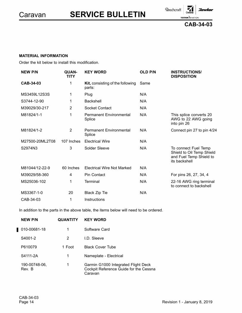
MATERIAL INFORMATIONOrder the kit below to install this modification.
NEW P/N QUAN-TITY
KEY WORD OLD P/N INSTRUCTIONS/DISPOSITION
CAB-34-03 1 Kit, consisting of the followingparts:
Same
MS3459L12S3S 1 Plug N/A
S3744-12-90 1 Backshell N/A
M39029/30-217 2 Socket Contact N/A
M81824/1-1 1 Permanent EnvironmentalSplice
N/A This splice converts 20AWG to 22 AWG goinginto pin 26
M81824/1-2 2 Permanent EnvironmentalSplice
N/A Connect pin 27 to pin 4/24
M27500-20ML2T08 107 Inches Electrical Wire N/A
S2974N3 3 Solder Sleeve N/A To connect Fuel TempShield to Oil Temp Shieldand Fuel Temp Shield toits backshell
M81044/12-22-9 60 Inches Electrical Wire Not Marked N/A
M39029/58-360 4 Pin Contact N/A For pins 26, 27, 34, 4
MS25036-102 1 Terminal N/A 22-16 AWG ring terminalto connect to backshell
MS3367-1-0 20 Black Zip Tie N/A
CAB-34-03 1 Instructions
In addition to the parts in the above table, the items below will need to be ordered.
NEW P/N QUANTITY KEY WORD
010-00681-18 1 Software Card
S4001-2 2 I.D. Sleeve
P610079 1 Foot Black Cover Tube
S4111-2A 1 Nameplate - Electrical
190-00748-06,Rev. B
1 Garmin G1000 Integrated Flight DeckCockpit Reference Guide for the CessnaCaravan
Caravan ATTACHMENTCAB-34-03
FLIGHT CREW OPERATIONS SUMMARY
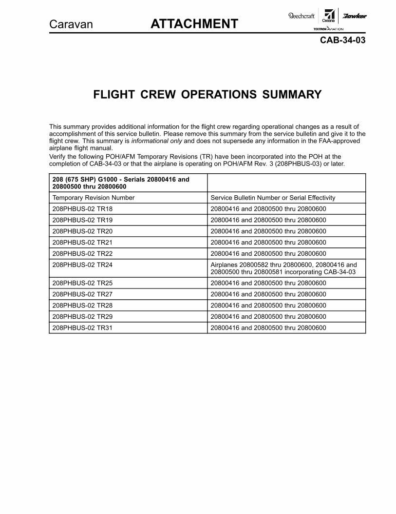
This summary provides additional information for the flight crew regarding operational changes as a result ofaccomplishment of this service bulletin. Please remove this summary from the service bulletin and give it to theflight crew. This summary is informational only and does not supersede any information in the FAA-approvedairplane flight manual.Verify the following POH/AFM Temporary Revisions (TR) have been incorporated into the POH at thecompletion of CAB-34-03 or that the airplane is operating on POH/AFM Rev. 3 (208PHBUS-03) or later.
208 (675 SHP) G1000 - Serials 20800416 and20800500 thru 20800600Temporary Revision Number Service Bulletin Number or Serial Effectivity
208PHBUS-02 TR18 20800416 and 20800500 thru 20800600
208PHBUS-02 TR19 20800416 and 20800500 thru 20800600
208PHBUS-02 TR20 20800416 and 20800500 thru 20800600
208PHBUS-02 TR21 20800416 and 20800500 thru 20800600
208PHBUS-02 TR22 20800416 and 20800500 thru 20800600
208PHBUS-02 TR24 Airplanes 20800582 thru 20800600, 20800416 and20800500 thru 20800581 incorporating CAB-34-03
208PHBUS-02 TR25 20800416 and 20800500 thru 20800600
208PHBUS-02 TR27 20800416 and 20800500 thru 20800600
208PHBUS-02 TR28 20800416 and 20800500 thru 20800600
208PHBUS-02 TR29 20800416 and 20800500 thru 20800600
208PHBUS-02 TR31 20800416 and 20800500 thru 20800600

Caravan ATTACHMENTCAB-34-03
Verify the following POH/AFM Temporary Revisions (TR) have been incorporated into the POH at thecompletion of CAB-34-03 or that the airplane is operating on POH/AFM Rev. 3 (208BPHBUS-03) or later.
208B (675 SHP) G1000 - Serials 208B1190,208B1216, 208B2000 thru 208B2196 and208B2198 thru 208B4999Temporary Revision Number Service Bulletin Number or Serial Effectivity
208BPHBUS-02 TR07 208B1190, 208B1216, 208B2000 thru 208B2196,and 208B2198 thru 208B4999
208BPHBUS-02 TR08 208B1190, 208B1216, 208B2000 thru 208B2196,and 208B2198 thru 208B4999
208BPHBUS-02 TR09 208B1190, 208B1216, 208B2000 thru 208B2196,and 208B2198 thru 208B4999
208BPHBUS-02 TR10 208B1190, 208B1216, 208B2000 thru 208B2196,and 208B2198 thru 208B4999
208BPHBUS-02 TR11 208B1190, 208B1216, 208B2000 thru 208B2196,and 208B2198 thru 208B4999
208BPHBUS-02 TR12 208B1190, 208B1216, 208B2000 thru 208B2196,and 208B2198 thru 208B4999
208BPHBUS-02 TR14 208B1190, 208B1216, 208B2000 thru 208B2196, and208B2198 thru 208B4999 incorporating CAB-34-03
208BPHBUS-02 TR15 208B1190, 208B1216, 208B2000 thru 208B2196,and 208B2198 thru 208B4999
208BPHBUS-02 TR17 208B1190, 208B1216, 208B2000 thru 208B2196,and 208B2198 thru 208B4999
208BPHBUS-02 TR18 208B1190, 208B1216, 208B2000 thru 208B2196,and 208B2198 thru 208B4999
208BPHBUS-02 TR19 208B1190, 208B1216, 208B2000 thru 208B2196,and 208B2198 thru 208B4999
Caravan ATTACHMENTCAB-34-03
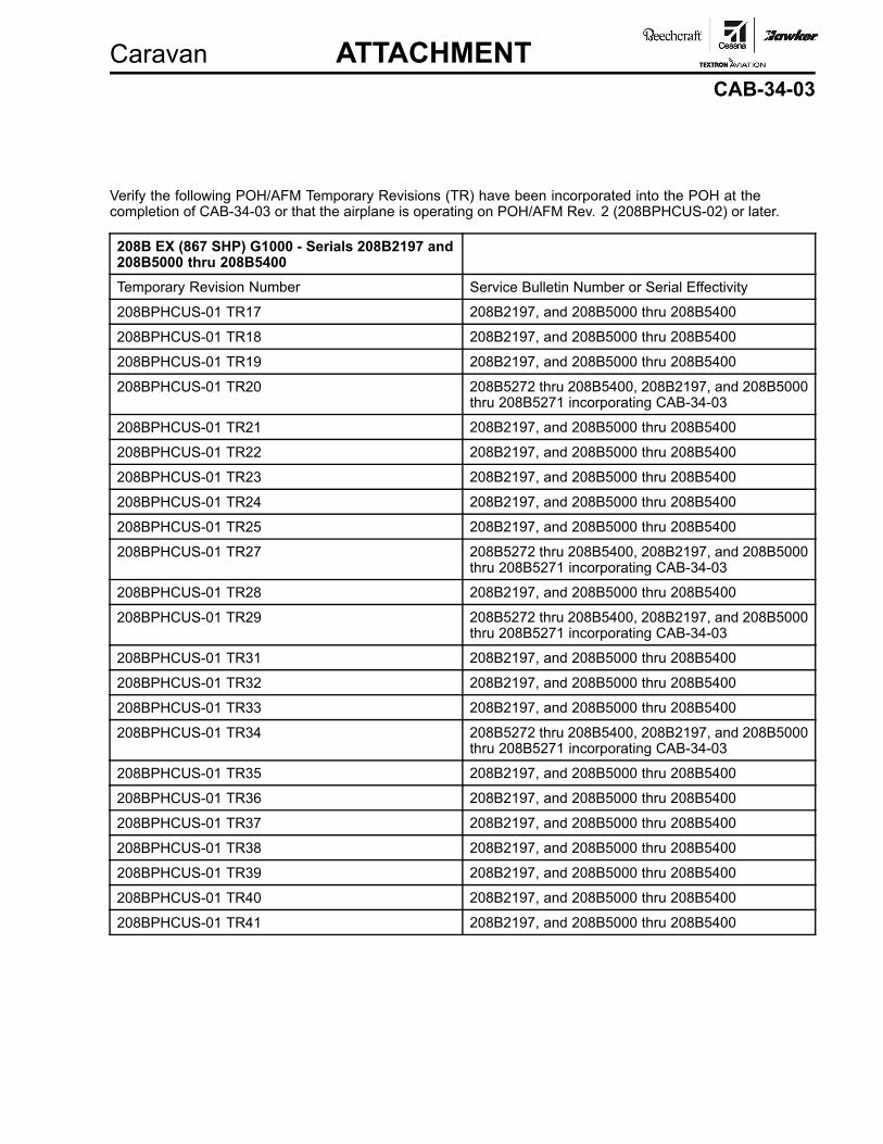
Verify the following POH/AFM Temporary Revisions (TR) have been incorporated into the POH at thecompletion of CAB-34-03 or that the airplane is operating on POH/AFM Rev. 2 (208BPHCUS-02) or later.
208B EX (867 SHP) G1000 - Serials 208B2197 and208B5000 thru 208B5400Temporary Revision Number Service Bulletin Number or Serial Effectivity
208BPHCUS-01 TR17 208B2197, and 208B5000 thru 208B5400
208BPHCUS-01 TR18 208B2197, and 208B5000 thru 208B5400
208BPHCUS-01 TR19 208B2197, and 208B5000 thru 208B5400
208BPHCUS-01 TR20 208B5272 thru 208B5400, 208B2197, and 208B5000thru 208B5271 incorporating CAB-34-03
208BPHCUS-01 TR21 208B2197, and 208B5000 thru 208B5400
208BPHCUS-01 TR22 208B2197, and 208B5000 thru 208B5400
208BPHCUS-01 TR23 208B2197, and 208B5000 thru 208B5400
208BPHCUS-01 TR24 208B2197, and 208B5000 thru 208B5400
208BPHCUS-01 TR25 208B2197, and 208B5000 thru 208B5400
208BPHCUS-01 TR27 208B5272 thru 208B5400, 208B2197, and 208B5000thru 208B5271 incorporating CAB-34-03
208BPHCUS-01 TR28 208B2197, and 208B5000 thru 208B5400
208BPHCUS-01 TR29 208B5272 thru 208B5400, 208B2197, and 208B5000thru 208B5271 incorporating CAB-34-03
208BPHCUS-01 TR31 208B2197, and 208B5000 thru 208B5400
208BPHCUS-01 TR32 208B2197, and 208B5000 thru 208B5400
208BPHCUS-01 TR33 208B2197, and 208B5000 thru 208B5400
208BPHCUS-01 TR34 208B5272 thru 208B5400, 208B2197, and 208B5000thru 208B5271 incorporating CAB-34-03
208BPHCUS-01 TR35 208B2197, and 208B5000 thru 208B5400
208BPHCUS-01 TR36 208B2197, and 208B5000 thru 208B5400
208BPHCUS-01 TR37 208B2197, and 208B5000 thru 208B5400
208BPHCUS-01 TR38 208B2197, and 208B5000 thru 208B5400
208BPHCUS-01 TR39 208B2197, and 208B5000 thru 208B5400
208BPHCUS-01 TR40 208B2197, and 208B5000 thru 208B5400
208BPHCUS-01 TR41 208B2197, and 208B5000 thru 208B5400

Caravan ATTACHMENTCAB-34-03
Verify the following POH/AFM Temporary Revisions (TR) have been incorporated into the POH at thecompletion of CAB-34-03 or that the airplane is operating on POH/AFM Rev. 2 (208BPHDUS-02) or later.
208B EX (867 SHP) G1000 with Fairing - Serials208B2197 and 208B5000 thru 208B5400Temporary Revision Number Service Bulletin Number or Serial Effectivity
208BPHDUS-01 TR17 208B2197, and 208B5000 thru 208B5400
208BPHDUS-01 TR18 208B2197, and 208B5000 thru 208B5400
208BPHDUS-01 TR19 208B2197, and 208B5000 thru 208B5400
208BPHDUS-01 TR20 208B5272 thru 208B5400, 208B2197, and 208B5000thru 208B5271 incorporating CAB-34-03
208BPHDUS-01 TR21 208B2197, and 208B5000 thru 208B5400
208BPHDUS-01 TR22 208B2197, and 208B5000 thru 208B5400
208BPHDUS-01 TR23 208B2197, and 208B5000 thru 208B5400
208BPHDUS-01 TR24 208B2197, and 208B5000 thru 208B5400
208BPHDUS-01 TR25 208B2197, and 208B5000 thru 208B5400
208BPHDUS-01 TR27 208B5272 thru 208B5400, 208B2197, and 208B5000thru 208B5271 incorporating CAB-34-03
208BPHDUS-01 TR28 208B2197, and 208B5000 thru 208B5400
208BPHDUS-01 TR29 208B5272 thru 208B5400, 208B2197, and 208B5000thru 208B5271 incorporating CAB-34-03
208BPHDUS-01 TR31 208B2197, and 208B5000 thru 208B5400
208BPHDUS-01 TR32 208B2197, and 208B5000 thru 208B5400
208BPHDUS-01 TR33 208B2197, and 208B5000 thru 208B5400
208BPHDUS-01 TR34 208B5272 thru 208B5400, 208B2197, and 208B5000thru 208B5271 incorporating CAB-34-03
208BPHDUS-01 TR35 208B2197, and 208B5000 thru 208B5400
208BPHDUS-01 TR36 208B2197, and 208B5000 thru 208B5400
208BPHDUS-01 TR37 208B2197, and 208B5000 thru 208B5400
208BPHDUS-01 TR38 208B2197, and 208B5000 thru 208B5400
208BPHDUS-01 TR39 208B2197, and 208B5000 thru 208B5400
208BPHDUS-01 TR40 208B2197, and 208B5000 thru 208B5400
208BPHDUS-01 TR41 208B2197, and 208B5000 thru 208B5400
Caravan OWNER ADVISORYCAB-34-03
TITLE
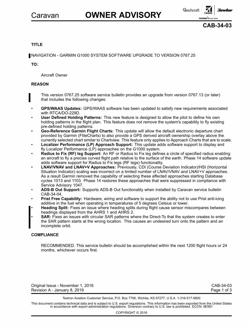
NAVIGATION - GARMIN G1000 SYSTEM SOFTWARE UPGRADE TO VERSION 0767.25
TO:
Aircraft Owner
REASON
This version 0767.25 software service bulletin provides an upgrade from version 0767.13 (or later)that includes the following changes:
• GPS/WAAS Updates: GPS/WAAS software has been updated to satisfy new requirements associatedwith RTCA/DO-229D.
• User Defined Holding Patterns: This new feature is designed to allow the pilot to define his ownholding patterns in the flight plan. This feature does not remove the system's capability to fly existingpre-defined holding patterns.
• Geo-Reference Garmin Flight Charts: This update will allow the default electronic departure chartprovided by Garmin (FliteCharts) to also provide a GPS derived aircraft ownership overlay above thecurrently selected chart similar to Chartview. This feature only applies to Approach Charts that are to scale.
• Localizer Performance (LP) Approach Support: This update adds software support to display andfly Localizer Performance (LP) approaches on the G1000 system.
• Radius to Fix (RF) leg Support: An RF or Radius to Fix leg defines a circle of specified radius enablingan aircraft to fly a precise curved flight path relative to the surface of the earth. Phase 14 software updateadds software support for Radius to Fix legs (RF legs) functionality.
• LNAV/VNAV and LNAV+V Approaches: Previously, CDI (Course Deviation Indicator)/HSI (HorizontalSituation Indicator) scaling was incorrect on a limited number of LNAV/VNAV and LNAV+V approaches.As a result Garmin removed the capability of selecting these affected approaches starting Databasecycles 1013 and 1103. Phase 14 restores these approaches that were suppressed in compliance withService Advisory 1047.
• ADS-B Out Support: Supports ADS-B Out functionality when installed by Caravan service bulletinCAB-34-04.
• Prist Free Capability: Hardware, wiring and software to support the ability not to use Prist anti-icingadditive in the fuel when operating in temperatures of 5 degrees Celsius or lower.
• Heading Split: Fixes an issue where heading splits during flight cause sensor miscompares betweenheadings displayed from the AHRS 1 and AHRS 2.
• SAR: Fixes an issues with circular SAR patterns where the Direct-To that the system creates to enterthe SAR pattern starts at the wrong location. This causes an undesired turn onto the pattern and anincomplete orbit.
COMPLIANCE
RECOMMENDED. This service bulletin should be accomplished within the next 1200 flight hours or 24months, whichever occurs first.
Original Issue - November 1, 2016 CAB-34-03Revision A - January 8, 2019 Page 1 of 3
Textron Aviation Customer Service, P.O. Box 7706, Wichita, KS 67277, U.S.A. 1-316-517-5800This document contains technical data and is subject to U.S. export regulations. This information has been exported from the United States
in accordance with export administration regulations. Diversion contrary to U.S. law is prohibited. ECCN: 9E991
COPYRIGHT © 2016

CAB-34-03Page 2 Revision A - January 8, 2019
Caravan OWNER ADVISORYCAB-34-03
LABOR HOURS
AIRPLANE CONFIGURATION LABOR-HOURSAirplanes with a software version earlier than 767.23: 16.0 to accomplish the wiring mod and upgrade
to software version 767.25
Airplanes upgrading to software version 767.25 only 3.0
MATERIAL AVAILABILITY
PART NUMBER AVAILABILITY COST
CAB-34-03 * *
010-00681-18 * *
S4001-2 * *
P610079 * *
S4111-2A * *
190-00748-06, Rev. B * *
* Please contact an Authorized Service Facility for current cost and availability of parts listed in thisservice document.
Based on availability and lead times, parts may require advanced scheduling.

Caravan OWNER ADVISORYCAB-34-03
WARRANTYThis bulletin is recommended. Eligible airplanes may qualify for parts and labor coverage to the extentnoted in the Labor Hours and Material Availability sections of this document.
Eligibility: All Group A airplanes identified within the serial number effectivity of this service documentwith software version earlier than 767.23, must have an active Airframe Warranty coverageon the Revision 1 issue date of this document and the coverage must be active on the daythe work is accomplished. All airplanes identified within the serial number effectivity inRevision 1 of this service document with software version 767.23 or 767.24 are eligible forwarranty coverage.
Parts Coverage: Textron Aviation-owned and Textron Aviation-authorized Service Facilities may submit aclaim for the parts required to accomplish this service document as defined in the MaterialAvailability section of this document.
Labor Coverage: Textron Aviation-owned and Textron Aviation-authorized Service Facilities rated to performmaintenance on the specific model of Cessna Aircraft may submit a claim for the labornecessary to accomplish this service document as defined in the Labor Hours section ofthis document.
CreditApplication:
After this service document has been accomplished, a claim must be submitted to TextronAviation within 30 days of the service document completion. Claims for compliance of thisservice document are to be filed as a W4 type claim.
Please submit your claim form online at ww2.txtav.com/Parts or email the completedTextron Aviation Claim Form to [email protected]. If submitted on-line a ReturnAuthorization will be provided. If a paper claim is submitted your claim will be entered in tothe system and a Return Authorization will be sent to you.
The Return Authorization must accompany any required return parts (see MaterialAvailability, to the point of purchase.
Parts to be returned to Textron Aviation Parts Distribution should be forwarded to:
Textron Aviation Parts DistributionWarranty Administration285 South Greenwich RoadBldg B89, Docks 1-4Wichita, KS 67206USA
Expiration: November 1, 2020
Textron Aviation reserves the right to void continued airplane warranty coverage for the parts affected bythis service document until the service document is accomplished.
NOTE: As a convenience, service documents are now available online to all our customers through asimple, free-of-charge registration process. If you would like to sign up, please visit the "CustomerAccess" link at www.txtavsupport.com to register.
CAB-34-03Revision A - January 8, 2019 Page 3
