service robotics and mechatronics · preface it is our great pleasure to hold the 2008...
TRANSCRIPT

Service Robotics and Mechatronics

Keiichi Shirase · Seiji Aoyagi
Service Robotics and Mechatronics
Selected Papers of the International Conference onMachine Automation ICMA2008
123

EditorsDr. Keiichi ShiraseKobe University
Dr. Seiji AoyagiKansai University
ISBN 978-1-84882-693-9 e-ISBN 978-1-84882-694-6DOI 10.1007/978-1-978-1-84882-694-6
British Library Cataloguing in Publication DataA catalogue record for this book is available from the British Library
Library of Congress Control Number: 2009938199
c© Springer-Verlag London Limited 2010
Apart from any fair dealing for the purposes of research or private study, or criticism or review, as per-mitted under the Copyright, Designs and Patents Act 1988, this publication may only be reproduced,stored or transmitted, in any form or by any means, with the prior permission in writing of the publis-hers, or in the case of reprographic reproduction in accordance with the terms of licenses issued by theCopyright Licensing Agency. Enquiries concerning reproduction outside those terms should be sent tothe publishers.The use of registered names, trademarks, etc., in this publication does not imply, even in the absence of aspecific statement, that such names are exempt from the relevant laws and regulations and therefore freefor general use.The publisher makes no representation, express or implied, with regard to the accuracy of the informationcontained in this book and cannot accept any legal responsibility or liability for any errors or omissionsthat may be made.
Cover design: eStudioCalamar, Figueres/Berlin
Printed on acid-free paper
Springer is part of Springer Science+Business Media (www.springer.com)
1-1 Rokko-daiNada657-8501 [email protected]
3-3-35 Yamate-choSuita564-8680 [email protected]
Springer London Dordrecht Heidelberg New York
PPrreeffaaccee
It is our great pleasure to hold the 2008 International Conference on Machine Automation at Awaji
Yumebutai International Conference Center. The conference is held every 2 years in Finland and Japan by
turns, and this is the 7th conference sponsored by Kansai University and the Japanese Council of
International Federation for Theory of Machines and Mechanism, in cooperation with 6 academic societies
and 2 institutes and organizations.
In a society with declining birth rate and rapidly aging population, even the senior citizen need to
take up active roles in daily life and social activities. In order to provide a safe living environment for them,
and for those who are handicapped, new technologies that can support their activities adequately are
required. Furthermore, in order to facilitate coexistence between man and machine, the design and
application of systems that take into account human psychology and movement need to be considered. The
shape and movement of the support robots that assist human beings in daily life must be designed with
judgment on the effects of their applications on human psychology. While more detailed surveillance are
required for monitoring system that monitor the daily life of human beings and the safety of the society, it is
also important that such systems do no overburden those being monitored. In addition to those, mechatronics
is also highly applicable in the area of reconstruction works after disasters, and restoration works on polluted
or abandoned environment due to chemical substances, land mines or other factors. In production plant, it is
expected the workers’ burden can be reduced by implementing autonomous distributed or unmanned
factory. Simply put, in order to ensure peace and safety to human society, the next generation robotics and
mechatronics systems are required to systematically analyze human psychology and movement, and based
on these results new system and machines will be developed.
This conference focuses on the topics and applications of such service robotics and mechatronics,
and 79 papers are accepted after careful screening for the presentation in 18 technical sessions including
rehabilitation, medical applications, robot, manufacturing, sensor, control, simulation, etc. Finally, two key
note papers and 66 papers are selected to publish the book titled “Service Robotics and Mechatoronics” after
the conference.
We would express our sincere appreciation and thanks to all the members of the Advisory
Committee, the Organizing Committee, the Program Committee, the reviewers, the chairs, and the staffs as
well as the participants for their good contribution and supports to hold this exciting conference.
KKeeiiiicchhii SShhiirraassee aanndd SSeeiijjii AAooyyaaggii
GGeenneerraall CCoo--CChhaaiirrss
v

vii
CCoonnffeerreennccee CCoommmmiitttteeeess
GGeenneerraall CCoo--CChhaaiirrss:: Aoyagi, S. (Kansai Univ., Japan) Shirase, K. (Kobe Univ., Japan)
AAddvviissoorryy CCoommmmiitttteeee:: Arai, E. (Osaka Univ., Japan) Arai, T. (Univ. of Tokyo, Japan) Arai, T. (Osaka Univ., Japan) Asama, H. (Univ. of Tokyo, Japan) Dohi, T. (Univ. of Tokyo, Japan) Fujie, M. (Waseda Univ., Japan) Fujimoto, H. (Nagoya Inst. of Tech., Japan) Fukuda, T. (Nagoya Univ., Japan) Higuchi, T. (Univ. of Tokyo, Japan) Hirose, S. (Tokyo Inst. of Tech., Japan) Hosaka, H. (Univ. of Tokyo, Japan) Inaba, M. (Univ. of Tokyo, Japan) Kamiya, Y. (Kanazawa Univ., Japan) Kaneko, M. (Osaka Univ., Japan) Kawamura, S. (Ritsumeikan Univ., Japan) Kivikoski, M. (Tampere Univ., Finland) Kosuge, K. (Tohoku Univ., Japan) Mae, Y. (Osaka Univ., Japan) Mitsuishi, M. (Univ. of Tokyo, Japan) Morimoto, Y. (Wakayama Univ., Japan) Sato, T. (Univ. of Tokyo, Japan) Sugano, S. (Waseda Univ., Japan)
OOrrggaanniizziinngg CCoommmmiitttteeee:: Aoyama, H. (Univ. of Electro-Communications, Japan) Hirai, S. (Ritsumeikan Univ., Japan) Kaihara, T. (Kobe Univ., Japan) Kume, Y. (Kinki Univ., Japan) Kurata, J. (Kansai Univ., Japan) Nakamoto, K. (Kobe Univ., Japan) Osumi, H. (Chuo Univ., Japan) Sakaguchi, T. (Kobe Univ., Japan) Sasaki, K. (Univ. of Tokyo, Japan) Seki, H. (Kanazawa Univ., Japan) Sugimura, N. (Osaka Pref. Univ., Japan) Taura, T. (Kobe Univ., Japan) Tejima, N. (Ritsumeikan Univ., Japan) Tsumaya, A. (Kobe Univ., Japan) Umeda, K. (Chuo Univ., Japan) Wakamatsu, E. (Osaka Univ., Japan)
PPrrooggrraamm CCoommmmiitttteeee:: Airila, M. (Helsinki Univ. of Tech., Finland) Conrad, F. (Technical Univ. of Denmark, Denmark) Ellman, A. (Tampere Univ. of Tech. / Seinäjoki Univ. Consortium, Finland) Fukushima, F. (Tokyo Inst. of Tech., Japan) Halme, A. (Helsinki Univ. of Tech., Finland) Handroos, H. (Lappeenranta Univ. of Tech., Finland) Hata, S. (Kagawa Univ., Japan) Hikitsu, M. (Kanazawa Univ., Japan) Hirata, Y. (Waseda Univ., Japan) Hosoda, K. (Osaka Univ., Japan) Inoue, K. (Yamagata Univ., Japan) Ivantysynova, M. (Purdue Univ., USA) Iwamura, K. (Osaka Pref. Univ., Japan) King, T. (Univ. of Leeds, U.K.) Komeda, T. (Shiraura Inst. of Tech., Japan) Koivo, H. (Helsinki Univ. of Tech., Finland) Krus, P. (Linköping Univ., Sweden) Matsubara, A. (Kyoto Univ., Japan) Mitsuyuki, K. (DENSO, Japan) Miwa, M. (Tokushima Univ., Japan) Mizugaki, Y. (Kyushu Inst. of Tech., Japan) Morita, T. (Univ. of Tokyo, Japan) Narita, H. (Nagoya Inst. of Tech., Japan) Peussa, P. (VTT Industrial systems, Finland) Ravina, E. (Univ. of Genoa, Italy) Röning, J. (Univ. of Oulu, Finland) Salminen, V. (Lappeenranta Univ. of Tech., Finland) Sashio, K. (Kobe Univ., Japan) Shiota, Y. (Polytechnic Univ., Japan) Sugita, N. (Univ. of Tokyo, Japan) Takubo, T. (Osaka Univ., Japan) Tani, K. (Gifu Univ., Japan) Tanimizu, Y. (Osaka Pref. Univ., Japan) Vähä, P. (VTT Electronics, Finland) Virvalo, T. (Tampere Univ. of Tech., Finland) Wikander, J. (The Royal Inst. of Tech., Sweden) Yamamoto, M. (Kyushu Univ., Japan)
Contents
Preface ································································································································································· v Conference Committees······································································································································ vii
ICMA Lectures Asko Ellman Designing Mobile Work Machines in Cyber Space ······························································································1 Yuichi Utsumi Proposal of 3D Micro Prototyping Using Synchrotron Radiation and Its Application to Bio-Microsystems ·········7
Medical applications Makoto Yagihashi, Hirohisa Narita and Hideo Fujimoto Surgical Tool Based Preoperative Planning System for Total Hip Arthroplasty ·················································15 Hirohisa Narita, Kakeru Harusawa, Makoto Yagihashi and Hideo Fujimoto A Trial of Numerical Calculation of Wear for Artificial Hip Joints ····································································21 Noriko Masuta, Makoto Yagihashi, Hirohisa Narita and Hideo Fujimoto A Non-invasive Method to Measure Joint Range of Motion for Hip Joints ························································27
Assembly Masaya Sanji, Tomonori Nakamura, Masato Suzuki and Seiji Aoyagi Robot Task of Pin Insertion to a Hole without Chamfering and with Small Clearance Using Fuzzy Control ······33 Hidefumi Wakamatsu, Minoru Matsuishi, Eiji Morinaga and Eiji Arai Disassembly Support System for Used Products Considering Destruction of Their Parts ··································37 Tohru Sasaki and Yoshihiro Sakai The Discriminative Method of the Insertion Using a Cantilever Model for the Optical Fiber Array Automatic Assemble ····························································································································································43 Tomomi Yamaguchi, Naomichi Furushiro and Masahiro Higuchi Application of the Active Flexible Fixture to a Peg-in-hole Task ·······································································49
Hydraulic and pneumatic control Tapio Virvalo Comparison of Tracking Controllers of Hydraulic Cylinder Drive by Simulations ·············································55 Y. Liu, H. Handroos, O. Alkkiomäki, V. Kyrki and H. Kälviäinen Development of a Hybrid Position/Force Controlled Hydraulic parallel Robot for Impact Treatment ···············61 Huapeng Wu, Pekka Pessi, Yongbo Wang and Heikki Handroos Modeling and Control of Water Hydraulic Driven Parallel Robot ······································································69
Rehabilitation and Orthosis systems Takehito Kikuchi, Sousuke Tanida,, Kikuko Otsuki, Taigo Kakehashi and Junji Furusho Development of Intelligent Ankle-Foot Orthosis (i-AFO) with MR Fluid Brake and Control System for Gait Control ·······························································································································································75 Takehito Kikuchi, Takuya Ozawa, , Kazuki Fukushima and Junji Furusho Development of Force-Measurable Grip and Software for "PLEMO", Rehabilitation System for Upper Limbs Based on Physical Therapy ·································································································································81 Ying Jin, Takehito Kikuchi, Junji Furusho and Hiroki Akai Mechanism Design and Software of Quasi-3-DOF Active-Passive Rehabilitation System for Upper Limbs, "Hybrid-PLEMO" ···············································································································································87 Kunihiko Oda, Yuuki Ohyama, Junji Furusho, Takehito Kikuchi and Shiro Isozumi 6-DOF Stand-Alone Rehabilitation System 'Robotherapist' and Its Applications to Stroke Patients ··················91
i x

Development of Grip Mechanism Assistant Device for Finger Rehabilitation ····················································95
Legged robots Satoshi Tsuda, Kuniya Shinozaki and Ryohei Nakatsu Development and Evaluation of a Centaur Robot ·····························································································101 Jining Liu, Yoshitsugu Kamiya, Hiroaki Seki and Masatoshi Hikizu Motion Simulation for a Stance Robot by Repeatedly Direct Kinematics ·························································107 Takuya Fukuda, Tomohito Takubo, Yasushi Mae and Tatsuo Arai Manipulation Method Using Wheeled-Hand Mechanism for Humanoid Robot ················································113 Masafumi Miwa, Hiroyasu Sakane, Kenji Nagase, Yasuhiro Koshimoto and Shigeki Tuchitani Study on One-legged Robot Jumping ···············································································································119
Control and Simulation Masafumi Miwa, Ittetsu Shiraishi, Makoto Matsushima and Kiyoshi Minami Remote Control Support System for R/C Helicopter ························································································125 Junso Kimura Finite-Time Settling Control restraining Amplitude of Control Input by Linear Programming ·························131 Koji Funamoto, Naoki Uchiyama, Masaya Hattori, Shigenori Sano and Shoji Takagi Robust Control of Mechanical Systems with Nonlinear Friction Considering Compliance of Transmission Mechanism ·······················································································································································137 Masahiko Kita, Tohru Ishida, Koji Teramoto and Yoshimi Takeuchi Size Reduction and Performance Improvement of Automatic Discharge Gap Controller for Curved Hole Electrical Discharge Machining ········································································································································143 Joni Sallinen, Tero Eskola and Heikki Handroos Design of a Motion Platform for a Mobile Machine Simulator by Utilizing 6-D Measurements and Inverse Dynamics Analysis ···········································································································································149
Position measurement Tomohiro Tanahashi, Akihiro Torii, Masaaki Banno, Akiteru Ueda and Kae Doki A Position Measurement Method for a Miniature Mobile Robot Using Three Moving Landmarks ··················153 Yasuhiro Kawahara, Hiroshi Yoshida and Hiroshi Hosaka Transport Equipment Positioning System Using Accelerometer and PHS ························································159 Xiaofeng Wu, Florent Servillat, Shinji Yamazaki, Tsuyoshi Taki, Ryohei Nakatsu, Masafumi Okajima, Tadashi Enomoto, Satoshi Kagami, Simon Thompson and Yoshifumi Nishida A Four-legged Robot Connected to Ubiquitous Devices in a Home ·································································165 Sho Komai, Tomomi Kuroda, Masaharu Takano, Seiji Aoyagi and Eiji Fukui Development of Invisible Mark and Its Application to a Home Robot ······························································171
Actuators Shinji Yamazaki, Yoshihiro Yasumuro and Masahiko Fuyuki Adaptive Polyhedral Subdivision for Image-based Lighting ·············································································177 Katsushi Furutani and Atsushi Furuta Comparison of Driving Performance of Piezoelectric Actuator - Current Pulse Drive and Voltage Linear Drive - ··········································································································································································183 Jun Iwasaki, Tomohiro Ishii, Satoru Yoshikawa, Hiroshi Hosaka and Ken Sasaki Steady State Analysis of Gyroscopic power Generator ·····················································································189 Yoichi Kadota, Hiroshi Hosaka and Takeshi Morita Characterization of Shape Memory Piezoelectric Actuator and Investigation of the Origin of the Imprint Electrical Field ·································································································································································195
Manufacturing systems Koji Iwamura, Norihisa Mayumi, Yoshitaka Tanimizu and Nobuhiro Sugimura
x
Shahrol Mohamaddan and Mohd Shahril Osman

A Study on Real-time Scheduling for Holonic Manufacturing Systems - Application of Reinforcement Learning -··········································································································································································201 Shigeru Harashima and Katsuhisa Ohno Flexible Production Systems developed and utilized in DENSO CORPORATION and their Evaluation ·········205 Kiyohiko Hori, Tsuneo Kawano and Keiichi Shirase Promotion Methods of Job Redesigning for Elderly Workers on the Production Line ······································211 Yoshitaka Tanimizu, Yoshiyuki Sakashita, Koji Iwamura and Nobuhiro Sugimura Human-Oriented Dynamic Task Reallocation and Rescheduling in Cellular Manufacturing Systems ··············217
Applicaion of vision Tatsuya Ogino, Yoshihiro Yasumuro and Masahiko Fuyuki Shape Data Registration based on Structured Light Pattern Direction ······························································223 Hiroyuki Ukida and Yasuyuki Yamanaka Object Tracking System Using Pan-Tilt Cameras and Arm Robot ····································································229
Driving support and Wheel chair Takafumi Asao, Kentaro Kotani and Ken Horii Influence of Reaching Actions on Driving Performance ···················································································235 Hideki Tomimori, Yoshio Ishida, Ken Sasaki, Yasuhiko Nakano and Satoshi Sano Measurement of a Car Driver’s Pulse Interval while Driving with One Hand ··················································241 Tatsuto Suzuki, Hironobu Uchiyama, Junichi Kurata, Yoshihiro Murakami and Masako Baba Validation of Performances on Attendant Propelled Wheelchairs with Assisting Control Based on Autonomous Propelling Model ··············································································································································245
Optimization and Reasoning Masahiro Arakawa Hierarchy Genetic Algorithm to Solve Multi-Objective Scheduling Problems Involving Various Types of Assignments for Parallel Processing System ·····································································································251 Yoshichika Tanaka, Hirohisa Narita, Ren Kanehira and Hideo Fujimoto Productivity Analysis of Closed-loop Manufacturing System Which Performs Maintenance Activities ···········257 Toshiya Kaihara, Nobutada Fujii, Hiroyuki Hasegawa and Shinji Kurose A Study on Optimization Method with Combinatorial Auction -Application to Resource Allocation Problem of Re-entrant Flow Shop- ·····································································································································263
Robots Atsushi Kohama, Ryosuke Mori, Sho Komai, Masato Suzuki, Seiji Aoyagi, Jun Fujioka and Yoshitsugu Kamiya Calibration of Kinematic Parameters of a Robot Using Neural Networks by a Laser Tracking System ············269 Kuniya Shinozaki, Akitsugu Iwatani and Ryohei Nakatsu Construction and Evaluation of a Robot Dance System ····················································································275 Masanori Goka, Akira Tsumaya and Toshiharu Taura Evolutionary Artificial Neural Networks using Extended Minimal Simulation on Evolutionary Robotics ········281 Hirofumi Niimi, Minoru Koike, Seiichi Takeuchi and Noriyoshi Douhara ROBO-BLOCK and Rational Formula of Robots ·····························································································287
Sensors Ryota Ishibashi, Ryuta Ozawa and Sadao Kawamura Experimental Verification of a Mass Measurement Device under Zero Gravity with a Prismatic Variable Stiffness Mechanism ·······················································································································································293 Takuro Aonuma, Shinya Kumagai, Minoru Sasaki, Motoki Tabata and Kazuhiro Hane Piezoresistive Rotation Angle Sensor in Micromirror for Feedback Control ·····················································299 Kenta Maekawa, Yoshito Tanaka, Takayuki Fujita and Kazusuke Maenaka Proposal of 2-axis Bulk-PZT Gyroscope ··········································································································305
i x

Jungmyoung Ju, , Yutaka Yamagata, Kozo Inoue and Toshiro Higuchi A Study on Atomization Characteristics of Surface Acoustic Wave Atomizer using Laser Doppler Anemometry ··········································································································································································309
Manufacturing Tatsuhiko Sakaguchi, Toshiaki Shimauchi and Keiichi Shirase Scheduling Based Collision Avoidance for Multitasking Machine ···································································313 Keiichi Nakamoto, Kouta Otake, Toshimichi Moriwaki and Keiichi Shirase Development of a Support System of Operation Planning for Parallel Kinematic Machine Tool ······················317 Eiji Morinaga, Yutaka Matsuura, Ryohei Satoh, Kouji Nakagawa, Reo Usui, Yoshiharu Iwata, Hidefumi Wakamatsu and Eiji Arai Method of Process Parameter Identification and Resist Profile Design for Thin-Film Pattern Formation ·········323 Michiya Matsushima, Naohiro Kawai, Hiroyuki Fujie, Kiyokazu Yasuda and Kozo Fujimoto Visual Inspection of Soldering Joints by Neural Network with Multi-angle View and Principal Component Analysis ····························································································································································329
Robot control Chikatoyo Nagata, Eri Sakamoto, Masato Suzuki and Seiji Aoyagi Path Generation and Collision Avoidance of Robot Manipulator for Unknown Moving Obstacle using Real-time Rapidly-exploring Random Trees (RRT) Method ·····························································································335 Kenji Hiraoka and Seiji Aoyagi Path Searching of a Robot Manipulator Using Reinforcement Learning and Self-Organizing Maps ·················341 Ali Muhammad, Jouni Mattila, Tapio Virvalo and Matti Vilenius Improved Positioning Accuracy for a Water Hydraulic Manipulator with State Feedback Controller ···············347 Hiroaki Ichii and Sadao Kawamura Trajectory Tracking Feedback Control of Robot Manipulators with Coupled Dynamics of Force and Position ··········································································································································································353
Elements and Components Norio Tagawa, Hisamitsu Yano and Atsunobu Mori Experimental Study of Lubricant Depletion in Laser-assisted Magnetic Recording ··········································359 Toshinori Ohashi, Hiroshi Hosaka and Takeshi Morita Light Transmittance Memory Effect of Ferroelectric Materials Induced by Electrical Imprint Field ················363
Machine tools Nelfa Desmira, Hirohisa Narita and Hideo Fujimoto A Minimization of Environmental Burden of High-Speed Milling ···································································367 Jun'ichi Kaneko, Koji Teramoto, Kenichiro Horio and Yoshimi Takeuchi Fast Estimation Method of Workpiece Shape in NC Machining Process for Prediction of Instantaneous Cutting Force ································································································································································373 Yoshitaka Morimoto Development of 2-dimensional Contouring by Endless Wire Saw ····································································379 Yasufumi Kume Application of Cusp Surface Analysis to Jumping Phenomenon ·······································································385 Authors’ Index ················································································································································391
i x i
Service Robotics and Mechatronics
Designing Mobile Work Machines in Cyber Space
Asko Ellman Dept. of Mechanics and Design, Tampere University of Technology, Tampere, Finland
Abstract Rapid development in ICT has made possible to accomplish detailed simulations of complete machine system in meaningful time and effort. Due to this, mechanical structures, power transmission, actuation and control systems can be designed more precisely. Furthermore, real-time simulation and hardware-in-the-loop simulation has enabled including of a human operator and real control system on the simulation. VR-technology together with user-centred design methods enables constructing of machines with good user experience. Keywords: Virtual Design; Mobile Work Machine, User Experience, Virtual Reality
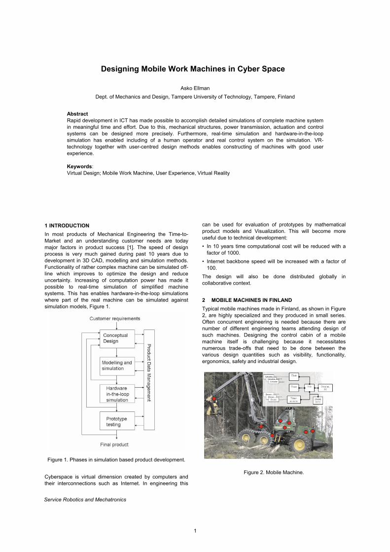
1 INTRODUCTION In most products of Mechanical Engineering the Time-to-Market and an understanding customer needs are today major factors in product success [1]. The speed of design process is very much gained during past 10 years due to development in 3D CAD, modelling and simulation methods. Functionality of rather complex machine can be simulated off-line which improves to optimize the design and reduce uncertainty. Increasing of computation power has made it possible to real-time simulation of simplified machine systems. This has enables hardware-in-the-loop simulations where part of the real machine can be simulated against simulation models, Figure 1.
Figure 1. Phases in simulation based product development. Cyberspace is virtual dimension created by computers and their interconnections such as Internet. In engineering this
can be used for evaluation of prototypes by mathematical product models and Visualization. This will become more useful due to technical development: • In 10 years time computational cost will be reduced with a
factor of 1000. • Internet backbone speed will be increased with a factor of
100. The design will also be done distributed globally in collaborative context. 2 MOBILE MACHINES IN FINLAND Typical mobile machines made in Finland, as shown in Figure 2, are highly specialized and they produced in small series. Often concurrent engineering is needed because there are number of different engineering teams attending design of such machines. Designing the control cabin of a mobile machine itself is challenging because it necessitates numerous trade-offs that need to be done between the various design quantities such as visibility, functionality, ergonomics, safety and industrial design.
Figure 2. Mobile Machine.
1
A. Ellman
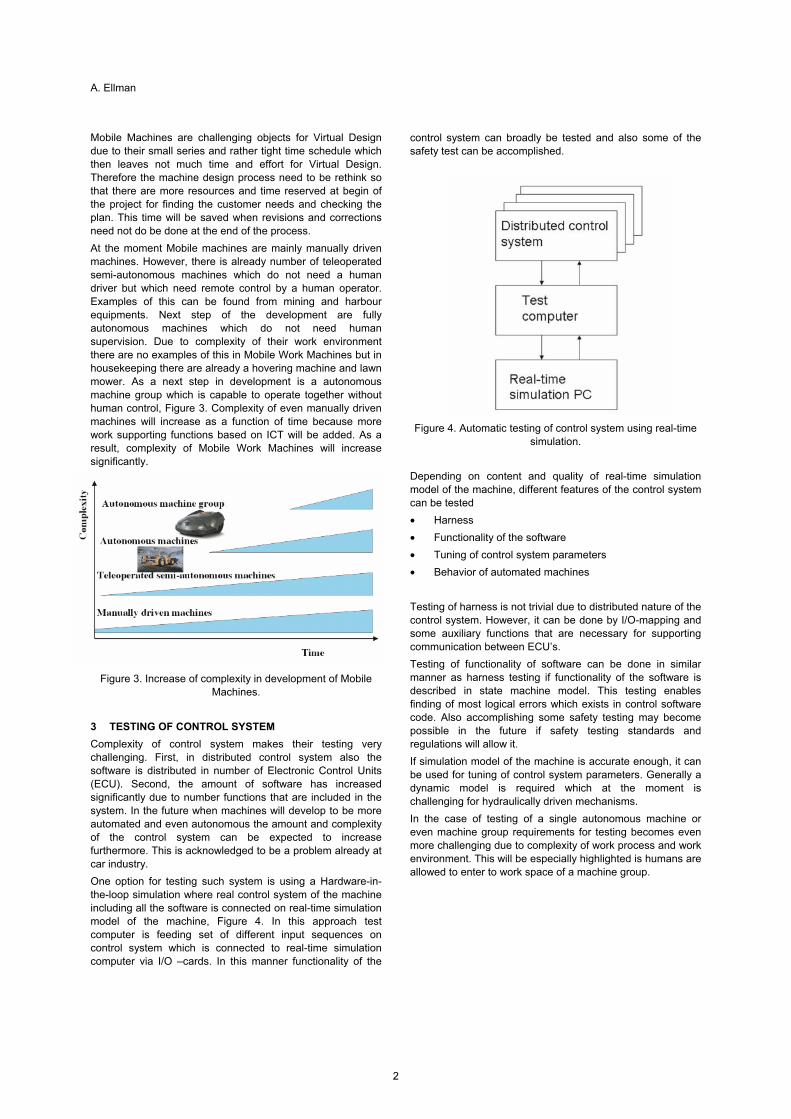
Mobile Machines are challenging objects for Virtual Design due to their small series and rather tight time schedule which then leaves not much time and effort for Virtual Design. Therefore the machine design process need to be rethink so that there are more resources and time reserved at begin of the project for finding the customer needs and checking the plan. This time will be saved when revisions and corrections need not do be done at the end of the process. At the moment Mobile machines are mainly manually driven machines. However, there is already number of teleoperated semi-autonomous machines which do not need a human driver but which need remote control by a human operator. Examples of this can be found from mining and harbour equipments. Next step of the development are fully autonomous machines which do not need human supervision. Due to complexity of their work environment there are no examples of this in Mobile Work Machines but in housekeeping there are already a hovering machine and lawn mower. As a next step in development is a autonomous machine group which is capable to operate together without human control, Figure 3. Complexity of even manually driven machines will increase as a function of time because more work supporting functions based on ICT will be added. As a result, complexity of Mobile Work Machines will increase significantly.
Figure 3. Increase of complexity in development of Mobile Machines.
3 TESTING OF CONTROL SYSTEM Complexity of control system makes their testing very challenging. First, in distributed control system also the software is distributed in number of Electronic Control Units (ECU). Second, the amount of software has increased significantly due to number functions that are included in the system. In the future when machines will develop to be more automated and even autonomous the amount and complexity of the control system can be expected to increase furthermore. This is acknowledged to be a problem already at car industry. One option for testing such system is using a Hardware-in-the-loop simulation where real control system of the machine including all the software is connected on real-time simulation model of the machine, Figure 4. In this approach test computer is feeding set of different input sequences on control system which is connected to real-time simulation computer via I/O –cards. In this manner functionality of the
control system can broadly be tested and also some of the safety test can be accomplished.
Figure 4. Automatic testing of control system using real-time simulation.
Depending on content and quality of real-time simulation model of the machine, different features of the control system can be tested • Harness • Functionality of the software • Tuning of control system parameters • Behavior of automated machines Testing of harness is not trivial due to distributed nature of the control system. However, it can be done by I/O-mapping and some auxiliary functions that are necessary for supporting communication between ECU’s. Testing of functionality of software can be done in similar manner as harness testing if functionality of the software is described in state machine model. This testing enables finding of most logical errors which exists in control software code. Also accomplishing some safety testing may become possible in the future if safety testing standards and regulations will allow it. If simulation model of the machine is accurate enough, it can be used for tuning of control system parameters. Generally a dynamic model is required which at the moment is challenging for hydraulically driven mechanisms. In the case of testing of a single autonomous machine or even machine group requirements for testing becomes even more challenging due to complexity of work process and work environment. This will be especially highlighted is humans are allowed to enter to work space of a machine group.
2
Designing Mobile Work Machines in Cyber Space
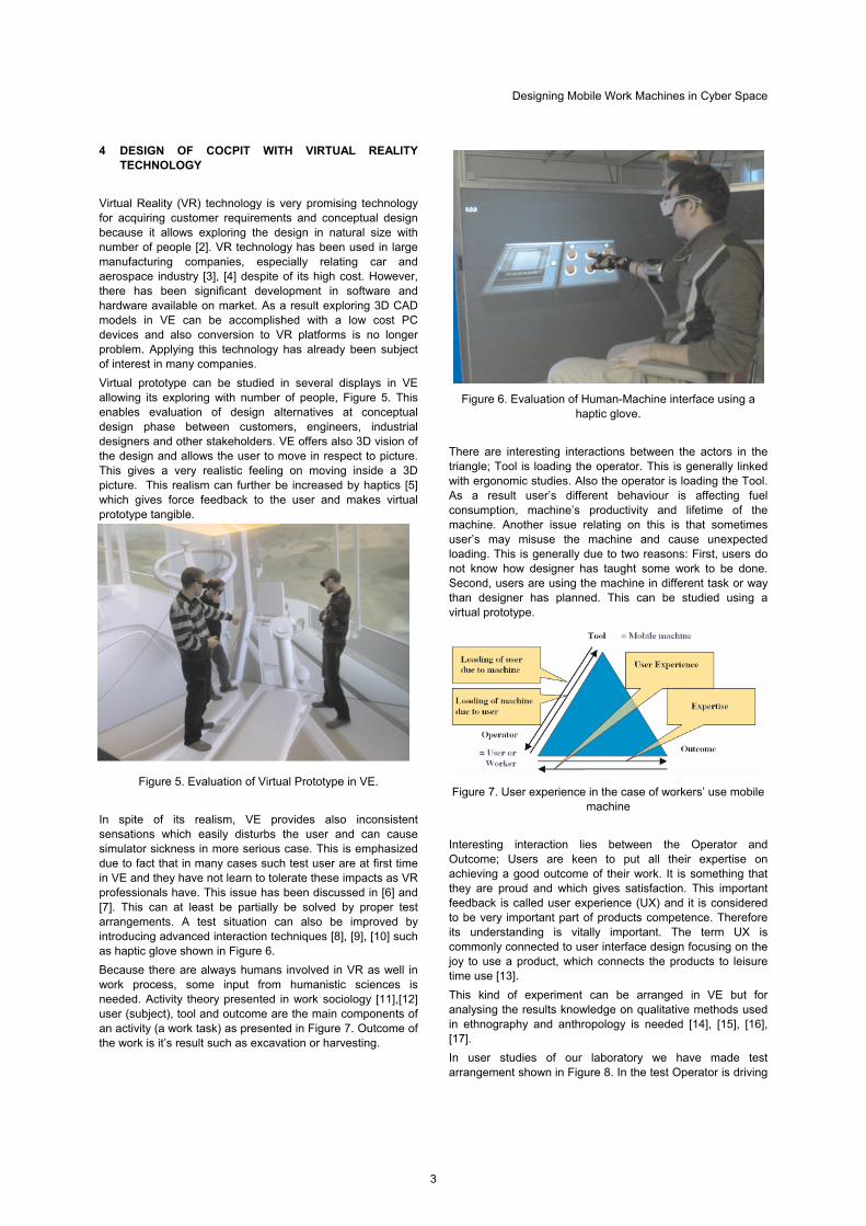
4 DESIGN OF COCPIT WITH VIRTUAL REALITY TECHNOLOGY
Virtual Reality (VR) technology is very promising technology for acquiring customer requirements and conceptual design because it allows exploring the design in natural size with number of people [2]. VR technology has been used in large manufacturing companies, especially relating car and aerospace industry [3], [4] despite of its high cost. However, there has been significant development in software and hardware available on market. As a result exploring 3D CAD models in VE can be accomplished with a low cost PC devices and also conversion to VR platforms is no longer problem. Applying this technology has already been subject of interest in many companies. Virtual prototype can be studied in several displays in VE allowing its exploring with number of people, Figure 5. This enables evaluation of design alternatives at conceptual design phase between customers, engineers, industrial designers and other stakeholders. VE offers also 3D vision of the design and allows the user to move in respect to picture. This gives a very realistic feeling on moving inside a 3D picture. This realism can further be increased by haptics [5] which gives force feedback to the user and makes virtual prototype tangible.
Figure 5. Evaluation of Virtual Prototype in VE. In spite of its realism, VE provides also inconsistent sensations which easily disturbs the user and can cause simulator sickness in more serious case. This is emphasized due to fact that in many cases such test user are at first time in VE and they have not learn to tolerate these impacts as VR professionals have. This issue has been discussed in [6] and [7]. This can at least be partially be solved by proper test arrangements. A test situation can also be improved by introducing advanced interaction techniques [8], [9], [10] such as haptic glove shown in Figure 6. Because there are always humans involved in VR as well in work process, some input from humanistic sciences is needed. Activity theory presented in work sociology [11],[12] user (subject), tool and outcome are the main components of an activity (a work task) as presented in Figure 7. Outcome of the work is it’s result such as excavation or harvesting.
Figure 6. Evaluation of Human-Machine interface using a haptic glove.
There are interesting interactions between the actors in the triangle; Tool is loading the operator. This is generally linked with ergonomic studies. Also the operator is loading the Tool. As a result user’s different behaviour is affecting fuel consumption, machine’s productivity and lifetime of the machine. Another issue relating on this is that sometimes user’s may misuse the machine and cause unexpected loading. This is generally due to two reasons: First, users do not know how designer has taught some work to be done. Second, users are using the machine in different task or way than designer has planned. This can be studied using a virtual prototype.
Figure 7. User experience in the case of workers’ use mobile machine
Interesting interaction lies between the Operator and Outcome; Users are keen to put all their expertise on achieving a good outcome of their work. It is something that they are proud and which gives satisfaction. This important feedback is called user experience (UX) and it is considered to be very important part of products competence. Therefore its understanding is vitally important. The term UX is commonly connected to user interface design focusing on the joy to use a product, which connects the products to leisure time use [13]. This kind of experiment can be arranged in VE but for analysing the results knowledge on qualitative methods used in ethnography and anthropology is needed [14], [15], [16], [17]. In user studies of our laboratory we have made test arrangement shown in Figure 8. In the test Operator is driving
3
A. Ellman
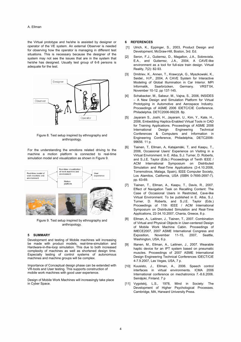
the Virtual prototype and he/she is assisted by designer or operator of the VE system. An external Observer is needed for observing how the operator is managing in different test situations. This is necessary because the designer of the system may not see the issues that are in the system that he/she has designed. Usually test group of 6-8 persons is adequate for the test.
Figure 8. Test setup inspired by ethnography and
anthropology. For the understanding the emotions related driving to the machine a motion platform is connected to real-time simulation model and visualization as shown in Figure 9.
Figure 9. Test setup inspired by ethnography and anthropology.
5 SUMMARY Development and testing of Mobile machines will increasing be made with product models, real-time-simulation and Hardware-in-the-loop simulation. This due to both increased complexity of machines as well as shortened design time. Especially testing of control systems of autonomous machines and machine groups will be complex. Importance of Conceptual design phase can be extended with VR-tools and User testing. This supports construction of mobile work machines with good user experience. Design of Mobile Work Machines will increasingly take place in Cyber Space.
6 REFERENCES [1] Ulrich, K., Eppinger, S., 2003, Product Design and
Development, McGraw-Hill, Boston, 3rd. Ed. [2] Seron, F.J., Gutierrez, D., Magallon, J.A., Sobreviela.
E.A., and Gutierrez, J.A., 2004, A CAVE-like environment as a tool for full-size train design. Virtual Reality, 7(2): 82-93.
[3] Dmitriev, K., Annen, T., Krawczyk, G., Myszkowski, K., Seidel., H.P., 2004, A CAVE System for Interactive Modeling of Global Illumination in Car Interior. MPI Informatik, Saarbrücken, Germany. VRST’04, November 10-12. pp 137-145.
[4] Schabacker, M., Sabeur, M., Vajna, S., 2006, INSIDES – A New Design and Simulation Platform for Virtual Prototyping in Automotive and Aerospace Industry. Proceedings of ASME 2006 IDETC/CIE Conference. Philadelphia. DETC2006-99228. 8p.
[5] Jayaram S., Joshi, H., Jayaram, U., Kim, Y., Kate, H., 2006, Embedding Haptics-Enabled Virtual Tools in CAD for Training Applications. Proceedings of ASME 2006 International Design Engineering Technical Conferences & Computers and Information in Engineering Conference, Philadelphia, DETC2006-99656. 11 p.
[6] Tiainen, T, Ellman, A, Katajamäki, T, and Kaapu, T., 2006, Occasional Users' Experience on Visiting in a Virtual Environment. In E. Alba, S.J. Turner, D. Roberts, and S.J.E. Taylor (Eds.) Proceedings of Tenth IEEE / ACM International Symposium on Distributed Simulation and Real-Time Applications (2-4.10.2006, Torremolinos, Malaga, Spain), IEEE Computer Society, Los Alamitos, California, USA (ISBN 0-7695-2697-7). pp. 63-69.
[7] Tiainen, T., Ellman, A., Kaapu, T., Davis, R., 2007. Effect of Navigation Task on Recalling Content: The Case of Occasional Users in Restricted, Cave-like Virtual Environment. To be published in E. Alba, S.J. Turner, D. Roberts, and S.J.E. Taylor (Eds.) Proceedings of 11th IEEE / ACM International Symposium on Distributed Simulation and Real-Time Applications, 22-34.10.2007, Chania, Greece, 8 p.
[8] Ellman, A., Laitinen, J., Tiainen, T., 2007. Combination of Virtual and Physical Objects in User-centered Design of Mobile Work Machine Cabin. Proceedings of IMECE2007, 2007 ASME International Congress and Exposition, November 11-15, 2007, Seattle, Washington, USA, 6 p.
[9] Iltanen, M., Ellman, A., Laitinen, J., 2007. Wearable haptic device for an IPT system based on pneumatic muscles. Proceedings of 2007 ASME International Design Engineering Technical Conferences IDECT/CIE 4-7.9.2007, Las Vegas, USA, 7 p.
[10] Kuusisto, J., Ellman, A., 2006. Speech control interfaces in virtual environments. ICMA 2006 International conference on mechatronics 7.-8.6.2006. Seinäjoki, Finland. 7 p
[11] Vygotskij, L.S., 1978, Mind in Society: The Development of Higher Psychological Processes. Cambridge, MA, Harward University Press.
4

Designing Mobile Work Machines in Cyber Space
[12] Engeström, Y., 1987, Learning by expanding, Orienta-konsultit, Helsinki.
[13] Nielsen, 2009, Nielsen Norman Group, Strategies to enhance the user experience. http://www.nngroup.com /about/userexperience.html obtained 30.1.2009
[14] Eriksen, T. H., 2001. Small places, big issues: An introduction to social and cultural anthropology. London: Pluto. (First edition 1995).
[15] Marton, F., 1981, Phenomenography – describing conceptions of the world around us, Instructional science, (10):177-200.
.
[16] Marton, F., 1982, Towards phenomenography of learning, Integratial experiments aspects, University of Gothenburg Dept. Education, Gothenburg.
[17] Meyer, C., and Schwager, A., 2007. Understanding Customer Experience. Harvard Business Review, February, 117-126.
5

Proposal of 3D Micro Prototyping Using Synchrotron Radiation and Its Application to Bio-Microsystems
Yuichi Utsumi
Laboratory of Advanced Science and Technology for Industry , University of Hyogo, Kamigori, Ako, Hyogo, Japan
Abstract A new X-ray microfabrication system and succeeding molding process as the 3D micro prototyping process have been developed using synchrotron radiation (SR) lithography and nano-imprinting technique. We adapted the process to the achievement of 3D microfluidic platforms for bio chemical applications which will be used point-of-care diagnostics and drug compound screenings. An enzyme linked immunosorbent assay method has been applied to the analysis of the endocrine disrupter using proposed fluidic platforms. Drastic improvement of the analysis sensitivity and decreasing of the total analysis effort and required time have confirmed Keywords: synchrotron radiation; microfabrication; microfluidics; Lab on chip; assay ; ELISA ;DNA
1 INTRODUCTION
There have been rapid developments in the application of microsystems in advanced industries such as intelligent information systems, energy and environment conservations, and medical and biochemical applications. Microsystems typically consist of different types of precise parts for various micro structures. The realization of 3D microstructures integrating multiple functions, such as electrical, optical, mechanical, and chemical sequential operations, in a restricted space will bring many advantages to the industry development. Systems of this type have been fabricated using micro-electro-mechanical system (MEMS) processes. Recently, however, fabrication techniques with a higher precision and a higher aspect ratio than those conventionally achievable have become increasingly important. This is due to the fact that natural phenomena on which these device functions are based, such as electrostatic fields, surface tension, and surface chemical reactions, tend to become more pronounced as specific surface area increases. To realize these requirement, we developed a new “3D micro prototyping process” based on X-ray microfabrication system equipped at the “NewSUBARU” SR facility [1,2]. and succeeding molding process using synchrotron radiation (SR) lithography and nano-imprinting technique. The stacking process as the device packaging of obtained micro structures is more essential where it needs various surface treatment and succeeding bonding process with different materials [3,4]. Meanwhile, the progress of life science has been increasing rapidly and the development of the platform technologies that supports it become more significant. Miniaturization and integration technology that have been successfully developed at microelectronics fields are nowadays adapting also to automated chemical analysis and synthesis, based on miniaturized total chemical system, so-called “TAS “ or “Lab on Chip” made from microfluidic components. We adapted proposed “3D micro prototyping process” to the achievement of the integrated microfluidic platform and have confirmed advantages of 3D micro-integration of chemical functions in one platform for some biochemical applications. A high sensitive and rapid enzyme linked immunosorbent assay (ELISA) method are demonstrated using micro 3D-structured
system consists of 3D microfluidic channel network and vertical chemical operation chamber with fluid control filter and mixer. Drastic improvement of the analysis sensitivity and decreasing the total analysis effort and required time have found in the applications to the environmental analysis and DNA analysis.
2 3D MICRO PROTOTYPING USING SYNCHROTRON RADIATION
2.1 3D X-ray Microfabrication System
The “lithographite, galvanoformung, abformung” (LIGA) process, which consists of deep-X-ray lithography, electroforming, and molding, is a promising candidate for 3D microfabrication[5]. The LIGA process starts from the fabrication of high-aspect-ratio polymer microstructures with heights greater than a few hundred microns using deep-X-ray lithography of a photosensitive polymer (resist) [6]. In the next step, a metal replica structure is formed by electroforming using the fabricated polymer master. The obtained metal replica structure can be used as a component in a High-Energy Beam ( 2-12 keV) Figure 1: Schematic diagram of newly developed lithography
system using SR.
X-RAY BEAMLINE
EXPOSURE
APPARATUS
X-ray mask
Electron storage
B
Be optical filter
Z-scan
e-
Cylindrical mirror
Low-Energy Beam ( < 2 keV)
Work
Service Robotics and Mechatronics
7
Y.Utsumi
0 500000 1000000 1500000 2000000 2500000 3000000
10
100
1000
Pro
cess
ing
depth
(μm
)
DOSE(mA・s )
1.5GeV High-Energy Spectrum 1.0GeV Low-Energy Spectrum
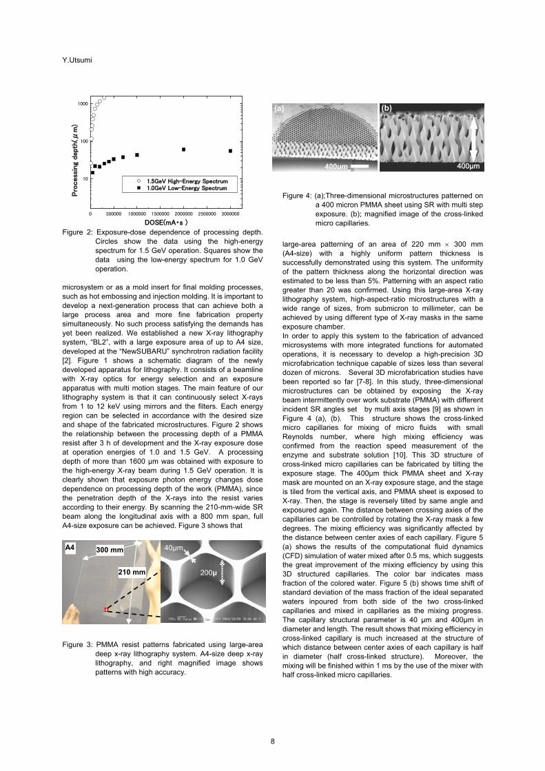
Figure 2: Exposure-dose dependence of processing depth.
Circles show the data using the high-energy spectrum for 1.5 GeV operation. Squares show the data using the low-energy spectrum for 1.0 GeV operation.
microsystem or as a mold insert for final molding processes, such as hot embossing and injection molding. It is important to develop a next-generation process that can achieve both a large process area and more fine fabrication property simultaneously. No such process satisfying the demands has yet been realized. We established a new X-ray lithography system, “BL2”, with a large exposure area of up to A4 size, developed at the “NewSUBARU” synchrotron radiation facility [2]. Figure 1 shows a schematic diagram of the newly developed apparatus for lithography. It consists of a beamline with X-ray optics for energy selection and an exposure apparatus with multi motion stages. The main feature of our lithography system is that it can continuously select X-rays from 1 to 12 keV using mirrors and the filters. Each energy region can be selected in accordance with the desired size and shape of the fabricated microstructures. Figure 2 shows the relationship between the processing depth of a PMMA resist after 3 h of development and the X-ray exposure dose at operation energies of 1.0 and 1.5 GeV. A processing depth of more than 1600 µm was obtained with exposure to the high-energy X-ray beam during 1.5 GeV operation. It is clearly shown that exposure photon energy changes dose dependence on processing depth of the work (PMMA), since the penetration depth of the X-rays into the resist varies according to their energy. By scanning the 210-mm-wide SR beam along the longitudinal axis with a 800 mm span, full A4-size exposure can be achieved. Figure 3 shows that Figure 3: PMMA resist patterns fabricated using large-area
deep x-ray lithography system. A4-size deep x-ray lithography, and right magnified image shows patterns with high accuracy.
Figure 4: (a);Three-dimensional microstructures patterned on
a 400 micron PMMA sheet using SR with multi step exposure. (b); magnified image of the cross-linked micro capillaries.
large-area patterning of an area of 220 mm 300 mm (A4-size) with a highly uniform pattern thickness is successfully demonstrated using this system. The uniformity of the pattern thickness along the horizontal direction was estimated to be less than 5%. Patterning with an aspect ratio greater than 20 was confirmed. Using this large-area X-ray lithography system, high-aspect-ratio microstructures with a wide range of sizes, from submicron to millimeter, can be achieved by using different type of X-ray masks in the same exposure chamber. In order to apply this system to the fabrication of advanced microsystems with more integrated functions for automated operations, it is necessary to develop a high-precision 3D microfabrication technique capable of sizes less than several dozen of microns. Several 3D microfabrication studies have been reported so far [7-8]. In this study, three-dimensional microstructures can be obtained by exposing the X-ray beam intermittently over work substrate (PMMA) with different incident SR angles set by multi axis stages [9] as shown in Figure 4 (a), (b). This structure shows the cross-linked micro capillaries for mixing of micro fluids with small Reynolds number, where high mixing efficiency was confirmed from the reaction speed measurement of the enzyme and substrate solution [10]. This 3D structure of cross-linked micro capillaries can be fabricated by tilting the exposure stage. The 400µm thick PMMA sheet and X-ray mask are mounted on an X-ray exposure stage, and the stage is tiled from the vertical axis, and PMMA sheet is exposed to X-ray. Then, the stage is reversely tilted by same angle and exposured again. The distance between crossing axies of the capillaries can be controlled by rotating the X-ray mask a few degrees. The mixing efficiency was significantly affected by the distance between center axies of each capillary. Figure 5 (a) shows the results of the computational fluid dynamics (CFD) simulation of water mixed after 0.5 ms, which suggests the great improvement of the mixing efficiency by using this 3D structured capillaries. The color bar indicates mass fraction of the colored water. Figure 5 (b) shows time shift of standard deviation of the mass fraction of the ideal separated waters inpoured from both side of the two cross-linked capillaries and mixed in capillaries as the mixing progress. The capillary structural parameter is 40 µm and 400µm in diameter and length. The result shows that mixing efficiency in cross-linked capillary is much increased at the structure of which distance between center axies of each capillary is half in diameter (half cross-linked structure). Moreover, the mixing will be finished within 1 ms by the use of the mixer with half cross-linked micro capillaries.
210 mm
300 mm A4
200μ
40μm
400µm.
(a) (b)
440000µµmm
8
Proposal of 3D Micro Prototyping Using Synchrotron Radiation and Its Application to Bio-Microsystems
(a) (b) Dose: 55 mA・hr
Dose: 165 mA・hr
Ts= 221Ts= 183℃Ts= 165℃Ts= 135℃
Ts= 164Ts=107℃ Ts= 116℃ Ts= 142℃
0.0000 0.0002 0.0004 0.0006 0.0008 0.00100.0
0.1
0.2
0.3
0.4
0.5
Sta
ndar
d d
evia
tion
Time [s]
℃
℃
Capillary form Full cross-linked
Half cross-linked Without cross-linked
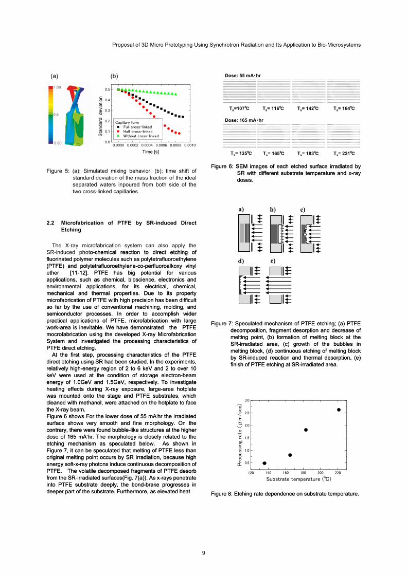
Figure 6: SEM images of each etched surface irradiated by
SR with different substrate temperature and x-ray doses.
Figure 6: SEM images of each etched surface irradiated by SR with different substrate temperature and x-ray doses.
Figure 5: (a); Simulated mixing behavior. (b); time shift of standard deviation of the mass fraction of the ideal separated waters inpoured from both side of the two cross-linked capillaries.
2.2 Microfabrication of PTFE by SR-induced Direct Etching
The X-ray microfabrication system can also apply the
SR-induced photo-chemical reaction to direct etching of fluorinated polymer molecules such as polytetrafluoroethylene (PTFE) and polytetrafluoroethylene-co-perfluoroalkoxy vinyl ether [11-12]. PTFE has big potential for various applications, such as chemical, bioscience, electronics and environmental applications, for its electrical, chemical, mechanical and thermal properties. Due to its property microfabrication of PTFE with high precision has been difficult so far by the use of conventional machining, molding, and semiconductor processes. In order to accomplish wider practical applications of PTFE, microfabrication with large work-area is inevitable. We have demonstrated the PTFE mocrofabrication using the developed X-ray Microfabrication System and investigated the processing characteristics of PTFE direct etching.
o-chemical reaction to direct etching of fluorinated polymer molecules such as polytetrafluoroethylene (PTFE) and polytetrafluoroethylene-co-perfluoroalkoxy vinyl ether [11-12]. PTFE has big potential for various applications, such as chemical, bioscience, electronics and environmental applications, for its electrical, chemical, mechanical and thermal properties. Due to its property microfabrication of PTFE with high precision has been difficult so far by the use of conventional machining, molding, and semiconductor processes. In order to accomplish wider practical applications of PTFE, microfabrication with large work-area is inevitable. We have demonstrated the PTFE mocrofabrication using the developed X-ray Microfabrication System and investigated the processing characteristics of PTFE direct etching.
At the first step, processing characteristics of the PTFE direct etching using SR had been studied. In the experiments, relatively high-energy region of 2 to 6 keV and 2 to over 10 keV were used at the condition of storage electron-beam energy of 1.0GeV and 1.5GeV, respectively. To investigate heating effects during X-ray exposure, large-area hotplate was mounted onto the stage and PTFE substrates, which cleaned with methanol, were attached on the hotplate to face the X-ray beam.
At the first step, processing characteristics of the PTFE direct etching using SR had been studied. In the experiments, relatively high-energy region of 2 to 6 keV and 2 to over 10 keV were used at the condition of storage electron-beam energy of 1.0GeV and 1.5GeV, respectively. To investigate heating effects during X-ray exposure, large-area hotplate was mounted onto the stage and PTFE substrates, which cleaned with methanol, were attached on the hotplate to face the X-ray beam. Figure 6 shows For the lower dose of 55 mA.hr the irradiated surface shows very smooth and fine morphology. On the contrary, there were found bubble-like structures at the higher dose of 165 mA.hr. The morphology is closely related to the etching mechanism as speculated below. As shown in Figure 7, it can be speculated that melting of PTFE less than original melting point occurs by SR irradiation, because high energy soft-x-ray photons induce continuous decomposition of PTFE. The volatile decomposed fragments of PTFE desorb from the SR-irradiated surfaces(Fig. 7(a)). As x-rays penetrate into PTFE substrate deeply, the bond-brake progresses in deeper part of the substrate. Furthermore, as elevated heat
Figure 6 shows For the lower dose of 55 mA.hr the irradiated surface shows very smooth and fine morphology. On the contrary, there were found bubble-like structures at the higher dose of 165 mA.hr. The morphology is closely related to the etching mechanism as speculated below. As shown in Figure 7, it can be speculated that melting of PTFE less than original melting point occurs by SR irradiation, because high energy soft-x-ray photons induce continuous decomposition of PTFE. The volatile decomposed fragments of PTFE desorb from the SR-irradiated surfaces(Fig. 7(a)). As x-rays penetrate into PTFE substrate deeply, the bond-brake progresses in deeper part of the substrate. Furthermore, as elevated heat
Figure 7: Speculated mechanism of PTFE etching; (a) PTFE decomposition, fragment desorption and decrease of melting point, (b) formation of melting block at the SR-irradiated area, (c) growth of the bubbles in melting block, (d) continuous etching of melting block by SR-induced reaction and thermal desorption, (e) finish of PTFE etching at SR-irradiated area.
Figure 7: Speculated mechanism of PTFE etching; (a) PTFE decomposition, fragment desorption and decrease of melting point, (b) formation of melting block at the SR-irradiated area, (c) growth of the bubbles in melting block, (d) continuous etching of melting block by SR-induced reaction and thermal desorption, (e) finish of PTFE etching at SR-irradiated area.
Figure 8: Etching rate dependence on substrate temperature. Figure 8: Etching rate dependence on substrate temperature.
a) b)
d) e)
c)
120 140 160 180 200 220
0.5
1.0
1.5
2.0
2.5
3.0
Pro
cess
ing
rate
(μ
m/se
c)
Substrate temperature (℃)
9
Y.Utsumi
contributes to rapid diffusion of decomposed PTFE molecules, it leads to the formation of large melting block expanding in entire exposed aria(Fig. 7(b)). This melting of PTFE was supposed o result in the abrupt rate increase around 165 degrees as shown in Figure 8. Decomposed fragments will agglutinated and results in the growth of the bubbles in melting block (Fig. 7(c)). Etching of melting block by SR-induced reaction and thermal desorption continuously progresses during these steps and finally the irradiated part will be selectively etched (Fig. 7(d,e)). By these processes, PTFE will be precisely etched by the use of developed lithography system.
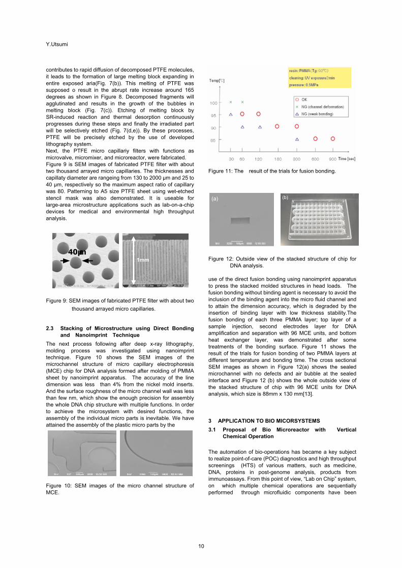
Next, the PTFE micro capillariy filters with functions as
microvalve, micromixer, and microreactor, were fabricated. Figure 9 is SEM images of fabricated PTFE filter with about
two thousand arrayed micro capillaries. The thicknesses and capillaty diameter are rangeing from 130 to 2000 µm and 25 to 40 µm, respectively so the maximum aspect ratio of capillary was 80. Patterning to A5 size PTFE sheet using wet-etched stencil mask was also demonstrated. It is useable for large-area microstructure applications such as lab-on-a-chip devices for medical and environmental high throughput analysis.
Figure 11: The result of the trials for fusion bonding.
(b)
Figure 9: SEM images of fabricated PTFE filter with about two
thousand arrayed micro capillaries.
2.3 Stacking of Microstructure using Direct Bonding and Nanoimprint Technique
The next process following after deep x-ray lithography, molding process was investigated using nanoimprint technique. Figure 10 shows the SEM images of the microchannel structure of micro capillary electrophoresis (MCE) chip for DNA analysis formed after molding of PMMA sheet by nanoimprint apparatus. The accuracy of the line dimension was less than 4% from the nickel mold inserts. And the surface roughness of the micro channel wall was less than few nm, which show the enough precision for assembly the whole DNA chip structure with multiple functions. In order to achieve the microsystem with desired functions, the assembly of the individual micro parts is inevitable. We have attained the assembly of the plastic micro parts by the Figure 10: SEM images of the micro channel structure of MCE.
Figure 12: Outside view of the stacked structure of chip for
DNA analysis. use of the direct fusion bonding using nanoimprint apparatus to press the stacked molded structures in head loads. The fusion bonding without binding agent is necessary to avoid the inclusion of the binding agent into the micro fluid channel and to attain the dimension accuracy, which is degraded by the insertion of binding layer with low thickness stability.The fusion bonding of each three PMMA layer; top layer of a sample injection, second electrodes layer for DNA amplification and separation with 96 MCE units, and bottom heat exchanger layer, was demonstrated after some treatments of the bonding surface. Figure 11 shows the result of the trials for fusion bonding of two PMMA layers at different temperature and bonding time. The cross sectional SEM images as shown in Figure 12(a) shows the sealed microchannel with no defects and air bubble at the sealed interface and Figure 12 (b) shows the whole outside view of the stacked structure of chip with 96 MCE units for DNA analysis, which size is 88mm x 130 mm[13]. 3 APPLICATION TO BIO MICORSYSTEMS
3.1 Proposal of Bio Microreactor with Vertical Chemical Operation
The automation of bio-operations has became a key subject to realize point-of-care (POC) diagnostics and high throughput screenings (HTS) of various matters, such as medicine, DNA, proteins in post-genome analysis, products from immunoassays. From this point of view, “Lab on Chip” system, on which multiple chemical operations are sequentially performed through microfluidic components have been
(b)
(a)
40µ m
1mm
10
Proposal of 3D Micro Prototyping Using Synchrotron Radiation and Its Application to Bio-Microsystems
attracted great attentions, because of their leading features such as compactness, small sample volume, fast and precisely controlled reaction, high analysis sensitivity, shortage of required time, reproducibility of output data, and low cost reliance. Such properties originated from down sizing of fluidic channels and components integrated monolithically which results in a large surface-area-to-volume ratio, a rapid thermal diffusion, a high pressure gradient, a high reagent
Pneumatic actuato Control and deta acquisition PC
Figure 13: Out view of the vertical reactor with capillary bundle structure.
Figure 14: Scheme of the high sensitive ELISA analysis using immunoreaction arisen with the antibody stacks immobilized inside the micro capillary wall.
Figure 15 : Out view of the automatic ELISA system using proposed vertical immuno reactor fabricated by SR lithography.
Figure 16: Calibration curve of nonylphenol concentration in the competitive ELISA.
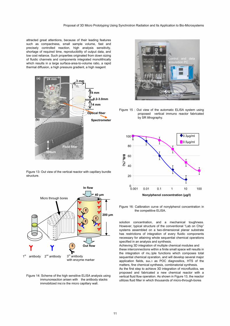
solution concentration, and a mechanical toughness. However, typical structure of the conventional “Lab on Chip” systems assembled on a two-dimensional planar substrate has restrictions of integration of every fluidic components necessary for attaining whole sequential chemical operations specified in an analysis and synthesis. Achieving 3D integration of multiple chemical modules and these interconnections within a finite small space will results in the integration of multiple functions which composes total sequential chemical operation, and will develop several major application fields, such as POC diagnositics, HTS of the matters, fine chemical synthesis, combinatorial synthesis. As the first step to achieve 3D integration of microfluidics, we proposed and fabricated a new chemical reactor with a vertical fluid flow operation. As shown in Figure 13, the reactor utilizes fluid filter in which thousands of micro-through-bores
70
0.2-3.0mm
14 mm
14 mm
3 mm
(b)
(a) 24 mm Vertival Reactor
Optical fiber
Spectrometer
Detection system using optical fiber
B/B
0 (%)
0.3 g/ml100
0.5 g/ml
Fluid filter
500 m
80
60
40
20
0In flow 0.001 0.01 0.1 1 10 100
3rd antibody with enzyme marker
E
2nd antibody 1st antibody
40 m
200 m
Micro through bores
E
EE
Nonylphenol concentration ( g/l)
Out flow
11

Y.Utsumi
chemical systems with whole bio-chemical processes, including sample pre-treatment, have not been developed, while it requires much efforts and time over separation and detection. The key-technology for the solution is assembly and interconnection technologies because seamless functional connection of various devices is necessary to acueve totally automated microchip systems. The various chemical operations must be realized on one platform to realize totally automated bio-process. We adapted proposed “3D micro prototyping process” to the achievement of such advanced systems and have confirmed the advantages of 3D micro-integration of chemical functions in one chip for DNA analysis and some immunoassay applications. We proposed 3D fluidic platform system in which total chemical unit operation necessary to achieve without human operations can perform automatically, which brings high analysis sensitivity and less total analysis effort and required time. In this concept whole procedure for immunoassay can be achievable by stacking multiple CD fluids with individual functions corresponds to each sequential step for bio-chemical operation to cover whole procedure for assay. This concept is shown as the schematic diagram of a new CD-like microfluidic platform with 3D fluid networks in Figure 17. In this system only necessary manual operation is loading of sample and reagent solutions into inlets. The analysis processes typically start with this sample purification followed by some sample preparation dilution and amplification. The purified samples are then mixed with buffer solutions containing another regents such as enzyme-labelled haptens by increasing the rotation speed of CD. The regents are pre-loaded in the other chamber formed on the bottom disk of the stack structure. The specific volumes of regent solutions and sample liquids are automatically injected into mixing chamber located in the middle disk of the stacked structure consists of three-dimensionally crossing channel network, and dispensed to desired volume ratios for designed protocol. For complete mixing of sample and regents the high-efficiency mixing device is necessary. For this purpose a 3D mixer with opposed-capillary structure is feasible at the mixing chamber. The mixture will next injected into biochemical reaction chamber with antibody immobilized 3D microstructure. Specific area of immobilized antibody become to be several decades times larger than conventional planar reactor microchannels, which results in the enhancement of the reaction rate and the analysis sensitivity, reproducibility of the immuno systems. The solution of product of bio-chemical reaction will then injected into detection chamber located after the reaction chamber and amount of the product will measured by using optical detection. Normally, optical path of micro channel on a conventional planer fluidic platform, which corresponds to the depth of the fluidic channel, is less than 100 micron and it has restrictions for detection such as difficulty of alignment and small signal due to the lack of optical path for absorption and fluorescence detection. On the other hand stacked CD structure can increase optical path up to several millimetres by forming detection channel across the stacked CDs.
are bundled, which sustains the liquids loaded from the first upper unit reservoir. For the step of the transportation of the sustained liquids towards the lower unit reservoir, pneumatic pressure will be loaded on the surface of the liquids. In the first step of loading of the reagents from the upper unit reservoir, different reagents are not mixed sufficiently due to the lowReynolds number of the reservoir. By the use of this fluid filter, it is assumed from the reaction rate measurement and computational fluidic dynamics simulations that different reagents are mixed entirely in a few milliseconds during their transportation from upper to lower reservoir and rapid chemical reactions can also be achieved; whereas, this filter can stock the reagent solutions with antibodies immobilized on the surface of the micro-through-bores, at which immuno reaction for ELISA occurs as shown in Figure 14 (sandwich method). We investigated the possibility of the analysis using the proposed vertical micro reactor for competitive enzyme-linked immunosorbent assay (ELISA), which enable highsensitive detection of an endocrine disrupter (nonylphenol) by a series of vertical fluidic operation. In this analysis, competition between nonylphenol and nonylphenol-Horseradish-peroxidase conjugate occurs at the binding of these molecules to anti-nonylphenol monoclonal antibody (anti-NP-antibody) immobilized on surface of the micro through bores as shown in Figure 9. In the assay using filters pretreated with 0.3 μg/ml of anti-NP-antibody, even at 0.01ng/ml of free NP, we still observed the inhibition of the binding (B/B0=90%). Whole analysis protocol have been performed using automatically operating system shown in Figure 15. Under this condition, calibration curve of NP was obtained at the range of 0.01-10ng/ml as shown in Figure 16. This sensitivity was two orders higher than the sensitivity (5-100 ng/ml) obtained by ordinary ELISA using 96-wells-micro-titer plate and the same anti-NP-antibody. These assays gave reproducible results, reactor to set at the centers of the filters[14-15].
3.2 3D Micro Fluidic Network
The miniaturized analysis chip such as microchip electrophoresis have been well developed, however the micro Sample loading and separation chamber (top layer) Figure 17: Schematic diagram of a new CD-like microfluidic
platform with 3D fluid networks.
3.3 Application of 3D Fluidic System to High Sensitive Elisa Immunoassay
The other benefits of the automation are realization of highly precise and reliable operations by reducing human errors or
3D CD platform device
Mixing chamber (middle layer)
Buffer solution reservoir (bottom layer)
Vertical bio-chemical reaction chamber
Optical detection chamber
Close up of analysis units
12
Proposal of 3D Micro Prototyping Using Synchrotron Radiation and Its Application to Bio-Microsystems
mistakes. One promising way to realize automation for immuassay is to utilize CD-like microfluidic platforms as mentioned above. In this section we will describe the detailed structure and protocol for ELISA with high-sensitive and high-speed, and high-reliable property of 3D CD platform devices. For automatic ELISA, the liquids, sample, wash, substrate, and reaction aborting solution are pre-loaded into reservoirs and sequentially injected into 3D bio-reaction chamber by spinning CD. For the first sequencing, the mixture
of sample and enzyme conjugated hapten will be injected and
competitively conjugate with 1st antibody immobilized on the
PC
Strobe
Spin controller
Synchronzied signal
CCD
Grabbed Images
CD platform
Strobe controller
CCD controller
Sensor controller
Figure :19 Schematic illustration and photograph of strobe
scope system
(a)
Figure:18 Illustration and photographs of designed and
fabricated CD platfrom consist of three layers
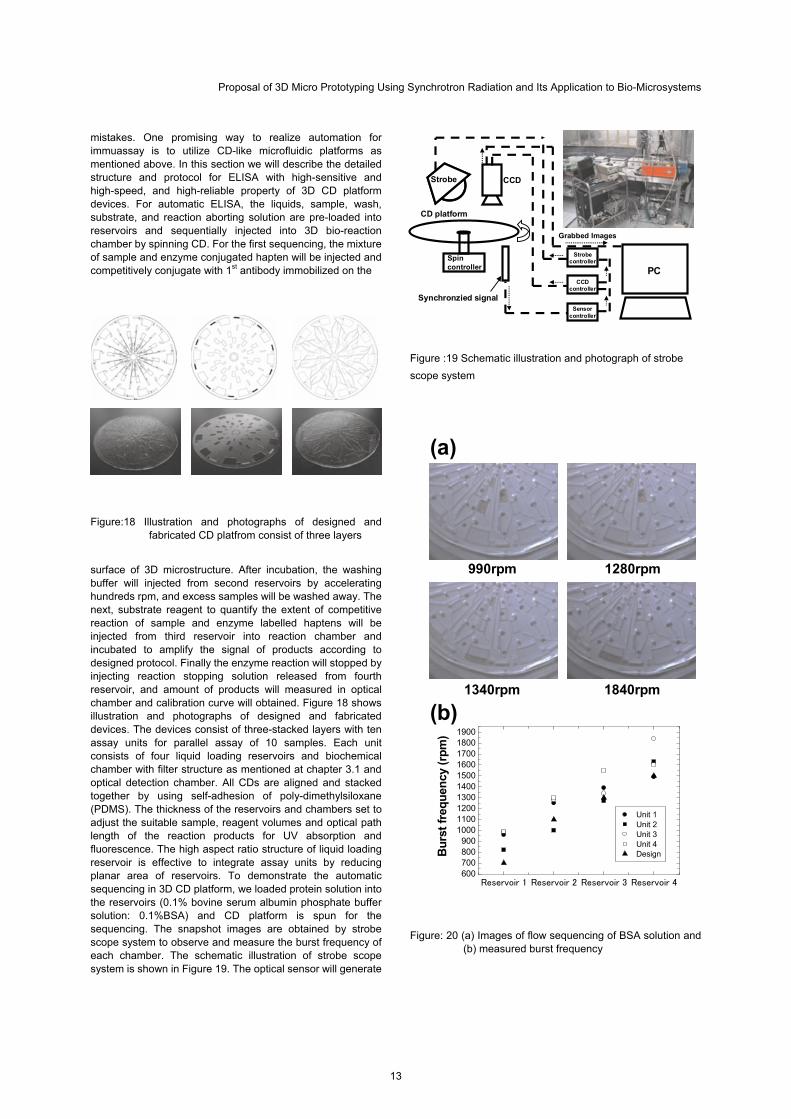
surface of 3D microstructure. After incubation, the washing buffer will injected from second reservoirs by accelerating hundreds rpm, and excess samples will be washed away. The next, substrate reagent to quantify the extent of competitive reaction of sample and enzyme labelled haptens will be injected from third reservoir into reaction chamber and incubated to amplify the signal of products according to designed protocol. Finally the enzyme reaction will stopped by injecting reaction stopping solution released from fourth reservoir, and amount of products will measured in optical chamber and calibration curve will obtained. Figure 18 shows illustration and photographs of designed and fabricated devices. The devices consist of three-stacked layers with ten assay units for parallel assay of 10 samples. Each unit consists of four liquid loading reservoirs and biochemical chamber with filter structure as mentioned at chapter 3.1 and optical detection chamber. All CDs are aligned and stacked together by using self-adhesion of poly-dimethylsiloxane (PDMS). The thickness of the reservoirs and chambers set to adjust the suitable sample, reagent volumes and optical path length of the reaction products for UV absorption and fluorescence. The high aspect ratio structure of liquid loading reservoir is effective to integrate assay units by reducing planar area of reservoirs. To demonstrate the automatic sequencing in 3D CD platform, we loaded protein solution into the reservoirs (0.1% bovine serum albumin phosphate buffer solution: 0.1%BSA) and CD platform is spun for the sequencing. The snapshot images are obtained by strobe scope system to observe and measure the burst frequency of each chamber. The schematic illustration of strobe scope system is shown in Figure 19. The optical sensor will generate
990rpm 1280rpm
1340rpm 1840rpm
Reservoir 1 Reservoir 2 Reservoir 3 Reservoir 4600700800900
1000110012001300140015001600170018001900
Bu
rst
freq
uen
cy (
rpm
)
Unit 1 Unit 2 Unit 3 Unit 4 Design
(b)
Figure: 20 (a) Images of flow sequencing of BSA solution and (b) measured burst frequency
13
Y.Utsumi
the trigger signals for the synchronized control of CCD and strobe. The taken images are automatically grabbed with time information into PC and burst frequency was calculated by checking holding state and the time.Figure15 (a) show the obtained images of automatic flow sequencing in 3D CD platform and measured burst frequencies are shown in Figure 20 (b). As shown in Figure20 (b) we succeeded in sequential transportation of BSA solution in four individual reactor units in 3D CD-like platforms. The result suggests the proposed 3D microfluidcs platform is available to automated ELISA analysis. 4 SUMMARY
3D micro prototyping process have been developed using synchrotron radiation (SR) lithography and nano-imprinting technique. Large-area patterning up to A4-size area was also successfully performed with a highly uniform pattern thickness. The X-ray microfabrication system can also apply the SR-induced photo-chemical reaction to direct etching of fluorinated polymer molecules. The stacking process as the device assembly and interconnections for obtained micro structures is also demonstrated using some types of surface treatment and succeeding nano-imprinting techniques for assembling 3D functional fluidic structure. We adapted proposed “3D micro prototyping process” to the achievement of 3D micro fluidic platforms and have confirmed the novel properties of high analysis sensitivity, speed, and low reagent consumption. for some assay applications. An enzyme linked immunosorbent assay method has been investigated using proposed micro 3D fluidic platforms in which thousands of micro capillary are integrated as a fluid control filter and bio-chemical reaction space in 3D fluid networks. Drastic improvement of the analysis sensitivity and decreasing the total analysis effort and required time have found in the applications for the environmental analysis. We also succeeded in sequential transportation of BSA solution in four individual reactor units in 3D CD-like platforms.
5 ACKNOWLEDGMENTS
This work has performed with the aides of New Energy Development Organization, Japan Society for the Promotion of Science, and COE program of Hyogo Prefecture, Japan.
6 REFERENCES
[1] A. Ando, T. Hattori, K. Hosono, K. Kanda, H. Kinoshita, S. Matsui, H. Mekaru, M. Niibe, Y. Utsumi and T. Watanabe : Journal of The Japanese Society for Synchrotron Radiation Research, 15, (2002) p. 336. [2] Y.Utsumi, and T. Kishimoto, Journal of. Vacuum. Science and Technologies. B, 23, 6, 2903-2909 (2005). [3] D.Fukuoka, and Y.Utsumi, p387., International Conference on Electronics Packaging 2008, JAPAN, June 2008 [4] Y. Utsumi, T. Ikeda, M. Minamitani, .K Suwa, p.125., 7th International Workshop on High-Aspect-Ratio Micro-Structure Technology 2007, FRANCE, June 2007 [5] F. J. Pantenburg, S. Achenbach and S. Mohr, Microsystems Tech. 4, (1998) 89. [6] E. W. Becker, W. Ehrfeld, P. Hagmann, A. Maner and D. Munchmeyer, Microelectronic Eng. 4, (1986) 35. [7] W. Ehrfeld : Proc. High Aspect Ratio Micro Structure Technology, 2001,(2001) p. 05.
[8] J. Goettert, G. Aigeldinger, Y. Desta, Z.L.Ling, and L. Rupp, Proc. Synchrotron Radiation Instrumentation, 2001, (2001) p. 102. [9] Y. Utsumi, M.Minamitani and T. Hattori : Electrical Engineering in japan , 165,1 (2008) p.52. [10] K. Fujiwara, Y. Ukita, M. Takeo, S. Negoro, T. Kanie, M. Katayama, and Y. Utsumi, p.297., 7th International Workshop on High-Aspect-Ratio Micro-Structure Technology 2007, FRANCE, June 2007 [11] Y. Ukita, M. Kishihara, Y.Haruyama, K. Kanda, S.Matsui, K. Michiji, and Y.Utsumi, Japanese Journal of Applied Physics, 47, pp. 337-341 (2008). [12] M. Kishihara, Y. Ukita, Y. Utsumi, and I. Ohta, p.301., 7th International Workshop on High-Aspect-Ratio Micro-Structure Technology 2007, FRANCE, June 2007 [13] Y.Utsumi, M.Minamitani and T. Hattori : Electrical Engineering in japan , 165,1 (2008) p.52. [14] Y.Utsumi, Y.Ukita, and T. sano, 51st International Conference on Electron Ion and Photon Beam Technology and Nanofabrication, USA, May 2007 [15] K. Matsui, I. Kawaji, Y. Utsumi, Y. Ukita, T. Asano, M. Takeo, D. Kato, and S. Negoro, Journal of Bioscience and Bioengineering,104, 4, 347-350 (2007). [16] M. J. Madou and G. J. Kellogg, Proc. SPIE, 3259,1998, p80-93 [17] S. Lai, S. Wang, J. Luo, L.J. Lee, S-T. Yang, and M. J. Madou, Anal. Chem., 76, 1832-1837, 2004 [18] Y-K. Cho, J-G. Lee, J-M Park, B-S. Lee,Y. Lee, and C. Ko, Lab. Chip, 7, 565-573, 2007.
14
Surgical Tool Based Preoperative Planning System for Total Hip Arthroplasty
Makoto Yagihashi1, Hirohisa Narita1 and Hideo Fujimoto1
1 Nagoya Institute of Technology, Nagoya, Japan
Abstract In preoperative planning of total hip arthroplasty, a type, a size and a place of a femoral stem is planned on plane radiographs or computed tomography images. However, the shape of the natural medullary cavity of the femur on these images differs from a prepared one expanded with reamers and rasps to insert the stem. This difference makes it hard to select an appropriate stem and its position without imagining behavior of surgical tools. In this paper, we propose a surgical tool based preoperative planning system for total hip arthroplasty to obtain a minimally invasive position of the stem. Keywords: Total hip arthroplasty; Preoperative planning; Minimally invasive surgery
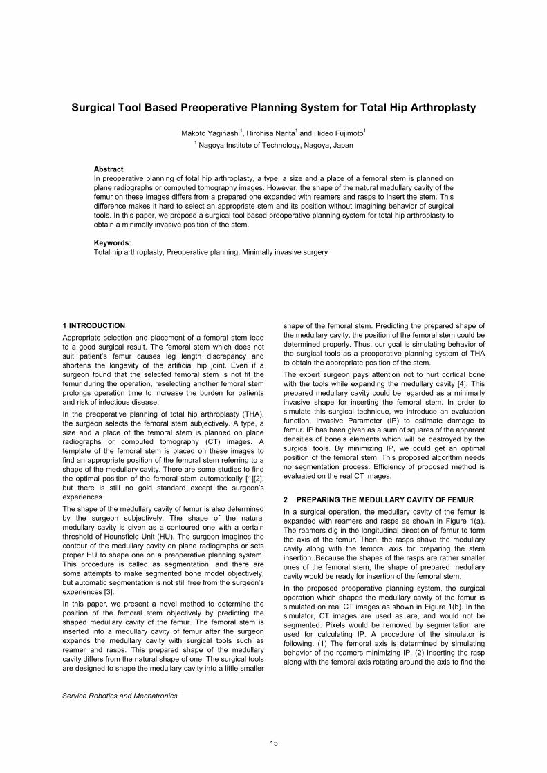
1 INTRODUCTION Appropriate selection and placement of a femoral stem lead to a good surgical result. The femoral stem which does not suit patient’s femur causes leg length discrepancy and shortens the longevity of the artificial hip joint. Even if a surgeon found that the selected femoral stem is not fit the femur during the operation, reselecting another femoral stem prolongs operation time to increase the burden for patients and risk of infectious disease. In the preoperative planning of total hip arthroplasty (THA), the surgeon selects the femoral stem subjectively. A type, a size and a place of the femoral stem is planned on plane radiographs or computed tomography (CT) images. A template of the femoral stem is placed on these images to find an appropriate position of the femoral stem referring to a shape of the medullary cavity. There are some studies to find the optimal position of the femoral stem automatically [1][2], but there is still no gold standard except the surgeon’s experiences. The shape of the medullary cavity of femur is also determined by the surgeon subjectively. The shape of the natural medullary cavity is given as a contoured one with a certain threshold of Hounsfield Unit (HU). The surgeon imagines the contour of the medullary cavity on plane radiographs or sets proper HU to shape one on a preoperative planning system. This procedure is called as segmentation, and there are some attempts to make segmented bone model objectively, but automatic segmentation is not still free from the surgeon’s experiences [3]. In this paper, we present a novel method to determine the position of the femoral stem objectively by predicting the shaped medullary cavity of the femur. The femoral stem is inserted into a medullary cavity of femur after the surgeon expands the medullary cavity with surgical tools such as reamer and rasps. This prepared shape of the medullary cavity differs from the natural shape of one. The surgical tools are designed to shape the medullary cavity into a little smaller
shape of the femoral stem. Predicting the prepared shape of the medullary cavity, the position of the femoral stem could be determined properly. Thus, our goal is simulating behavior of the surgical tools as a preoperative planning system of THA to obtain the appropriate position of the stem. The expert surgeon pays attention not to hurt cortical bone with the tools while expanding the medullary cavity [4]. This prepared medullary cavity could be regarded as a minimally invasive shape for inserting the femoral stem. In order to simulate this surgical technique, we introduce an evaluation function, Invasive Parameter (IP) to estimate damage to femur. IP has been given as a sum of squares of the apparent densities of bone’s elements which will be destroyed by the surgical tools. By minimizing IP, we could get an optimal position of the femoral stem. This proposed algorithm needs no segmentation process. Efficiency of proposed method is evaluated on the real CT images. 2 PREPARING THE MEDULLARY CAVITY OF FEMUR In a surgical operation, the medullary cavity of the femur is expanded with reamers and rasps as shown in Figure 1(a). The reamers dig in the longitudinal direction of femur to form the axis of the femur. Then, the rasps shave the medullary cavity along with the femoral axis for preparing the stem insertion. Because the shapes of the rasps are rather smaller ones of the femoral stem, the shape of prepared medullary cavity would be ready for insertion of the femoral stem. In the proposed preoperative planning system, the surgical operation which shapes the medullary cavity of the femur is simulated on real CT images as shown in Figure 1(b). In the simulator, CT images are used as are, and would not be segmented. Pixels would be removed by segmentation are used for calculating IP. A procedure of the simulator is following. (1) The femoral axis is determined by simulating behavior of the reamers minimizing IP. (2) Inserting the rasp along with the femoral axis rotating around the axis to find the
Service Robotics and Mechatronics
15

M.Yagihashi, H.Narita and H.Fujimoto
position with minimal IP. Finally, the position of the optimal position of the femoral stem is given as one of the final rasp.
Figure 1: Preparing a shape of a medullary cavity of femur. 3 ESTIMATING INVASIVENESS
3.1 A Model of the femur Before explaining about IP, the model of femur for the proposed simulation is to be described. The femur is modelled as several slices of CT images as shown in Figure 2. Each CT slice has zero thick and placed referring to its DICOM header. Ordinarily, voxels are used in the field of visualization and analysis of medical data, however handling CT images as voxels increases calculating time for collision detection and errors cased by similar reason to the partial volume effect. A collision between the bone and the tool is detected by simplly finding the pixels inside of the models of the surgical tools.
3.2 Invasive Parameter (IP) The reamers and rasps are operated according to not only the preoperative plan, but also the reaction force through the tools in the operation. The tool working as a probe allows the expert surgeon to decrease invasiveness while expanding the medullary cavity. Invasive Parameter: IP is introduced to estimate this reaction force through the tools. IP has been given as following,
,)(IP1 1
2∑∑= =
=CT pixeln
i
n
j
HUijk (1)
where, k is constant can be 1 here,
CTn is number of CT images,
pixeln is number of the pixels interfering the tool
ijHU is Hounsfield Units (HU) of the pixels
( 0=ijHU if 0<ijHU here)
The reaction force is regarded as being proportionate to a sum of compressive strength of each element of the bone is to be removed by the tool. The compressive strength can be assumed to be proportionate to the square of the bone density [6]. Thus, IP is proportionate to a sum of the squared HU of the each pixel in the CT images. A minimally invasive position of the tool is estimated by minimizing IP. 4 REAMING SIMULATION
4.1 A model of the reamer In THA, tapered reamers are used to expand the medullary cavity of femur. In the reaming simulator, the reamer is modelled as a cylinder to ignore the depths of insertion of the reamer to simplify the model. A schematic diagram of the reaming simulation is shown in Figure 3. A diameter of the reamer starts from 1mm and increased by 1mm to 7mm in this evaluation.
Figure 2: A model for calculating invasiveness.
16
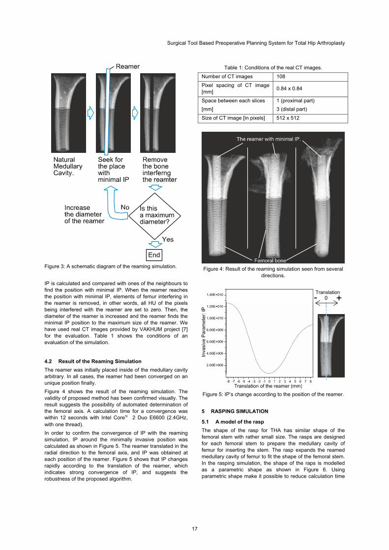
Surgical Tool Based Preoperative Planning System for Total Hip Arthroplasty
Figure 3: A schematic diagram of the reaming simulation.
IP is calculated and compared with ones of the neighbours to find the position with minimal IP. When the reamer reaches the position with minimal IP, elements of femur interfering in the reamer is removed, in other words, all HU of the pixels being interfered with the reamer are set to zero. Then, the diameter of the reamer is increased and the reamer finds the minimal IP position to the maximum size of the reamer. We have used real CT images provided by VAKHUM project [7] for the evaluation. Table 1 shows the conditions of an evaluation of the simulation.
4.2 Result of the Reaming Simulation The reamer was initially placed inside of the medullary cavity arbitrary. In all cases, the reamer had been converged on an unique position finally. Figure 4 shows the result of the reaming simulation. The validity of proposed method has been confirmed visually. The result suggests the possibility of automated determination of the femoral axis. A calculation time for a convergence was within 12 seconds with Intel Core™ 2 Duo E6600 (2.4GHz, with one thread). In order to confirm the convergence of IP with the reaming simulation, IP around the minimally invasive position was calculated as shown in Figure 5. The reamer translated in the radial direction to the femoral axis, and IP was obtained at each position of the reamer. Figure 5 shows that IP changes rapidly according to the translation of the reamer, which indicates strong convergence of IP, and suggests the robustness of the proposed algorithm.
Table 1: Conditions of the real CT images.
Number of CT images 108
Pixel spacing of CT image [mm] 0.84 x 0.84
Space between each slices [mm]
1 (proximal part) 3 (distal part)
Size of CT image [in pixels] 512 x 512
Figure 4: Result of the reaming simulation seen from several
directions.
Figure 5: IP’s change according to the position of the reamer.
5 RASPING SIMULATION
5.1 A model of the rasp The shape of the rasp for THA has similar shape of the femoral stem with rather small size. The rasps are designed for each femoral stem to prepare the medullary cavity of femur for inserting the stem. The rasp expands the reamed medullary cavity of femur to fit the shape of the femoral stem. In the rasping simulation, the shape of the raps is modelled as a parametric shape as shown in Figure 6. Using parametric shape make it possible to reduce calculation time
17
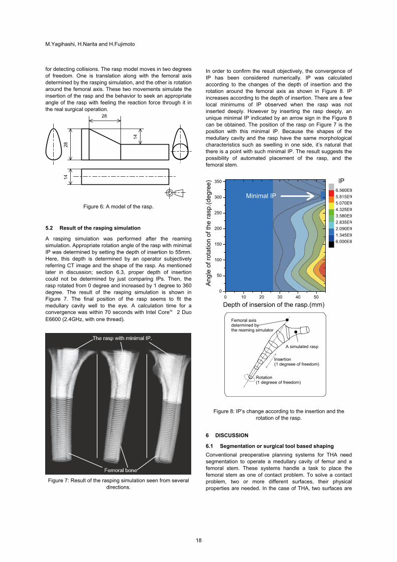
M.Yagihashi, H.Narita and H.Fujimoto
for detecting collisions. The rasp model moves in two degrees of freedom. One is translation along with the femoral axis determined by the rasping simulation, and the other is rotation around the femoral axis. These two movements simulate the insertion of the rasp and the behavior to seek an appropriate angle of the rasp with feeling the reaction force through it in the real surgical operation.
Figure 6: A model of the rasp.
5.2 Result of the rasping simulation
A rasping simulation was performed after the reaming simulation. Appropriate rotation angle of the rasp with minimal IP was determined by setting the depth of insertion to 55mm. Here, this depth is determined by an operator subjectively referring CT image and the shape of the rasp. As mentioned later in discussion; section 6.3, proper depth of insertion could not be determined by just comparing IPs. Then, the rasp rotated from 0 degree and increased by 1 degree to 360 degree. The result of the rasping simulation is shown in Figure 7. The final position of the rasp seems to fit the medullary cavity well to the eye. A calculation time for a convergence was within 70 seconds with Intel Core™ 2 Duo E6600 (2.4GHz, with one thread).
Figure 7: Result of the rasping simulation seen from several
directions.
In order to confirm the result objectively, the convergence of IP has been considered numerically. IP was calculated according to the changes of the depth of insertion and the rotation around the femoral axis as shown in Figure 8. IP increases according to the depth of insertion. There are a few local minimums of IP observed when the rasp was not inserted deeply. However by inserting the rasp deeply, an unique minimal IP indicated by an arrow sign in the Figure 8 can be obtained. The position of the rasp on Figure 7 is the position with this minimal IP. Because the shapes of the medullary cavity and the rasp have the same morphological characteristics such as swelling in one side, it’s natural that there is a point with such minimal IP. The result suggests the possibility of automated placement of the rasp, and the femoral stem.
Figure 8: IP’s change according to the insertion and the rotation of the rasp.
6 DISCUSSION
6.1 Segmentation or surgical tool based shaping Conventional preoperative planning systems for THA need segmentation to operate a medullary cavity of femur and a femoral stem. These systems handle a task to place the femoral stem as one of contact problem. To solve a contact problem, two or more different surfaces, their physical properties are needed. In the case of THA, two surfaces are
18
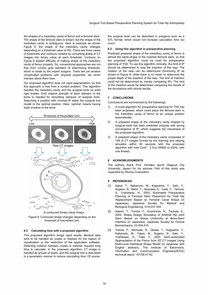
Surgical Tool Based Preoperative Planning System for Total Hip Arthroplasty
the shapes of a medullary cavity of femur and a femoral stem. The shape of the femoral stem is known, but the shape of the medullary cavity is ambiguous. Here is example as shown Figure 9, the shape of the medullary cavity changes depending on a threshold value of HU. There are three cases of thresholds and contours created by converting pixels of CT images into binary value at each threshold. Contours on Figure 9 explain difficulty of making shape of the medullary cavity of femur properly. So, conventional approaches are not free from current gold standard of determining threshold, which is made by the expert surgeon. There are yet another complicated problems with physical properties, we never mention about them here. Our proposed algorithm does not need segmentation, so that this approach is free from a contact problem. This algorithm handles the medullary cavity and the surgical tools as solid rigid bodies. Only relative strength of each element of the bone is needed for simulating behavior of surgical tools. Searching a position with minimal IP leads the surgical tool model to the optimal position. Here, ‘optimal’ means having least invasive to the bone.
Figure 9: Contoured shape changes depending on the
threshold of Hounsfield Unit.
6.2 Calculating time with a proposed algorithm This proposed algorithm brings rapid results. Medical data tend to be handled as voxels or meshes for the reason of visualization or the restriction of the application software. Detecting collision between voxels or meshes requires long time to calculate. In the proposed algorithm, CT image is handled as groups of pixels, and the surgical tool is described in a parametric manner to reduce calculating time. Of course,
the surgical tools can be described in polygons such as a STL format, which would not increase calculation time too much.
6.3 Using this algorithm in preoperative planning Predicted prepared shape of the medullary cavity of femur is almost the same shape of the inserted femoral stem, so that the proposed algorithm could be used for preoperative planning of THA. To use this algorithm clinically, the limit of IP should be determined to stop the insertion of the rasp. The rotation of the rasp can be determined minimizing IP as shown in Figure 8, while there is no mean to determine the proper depth of the insertion of the rasp. The limit of insertion could not be determined by merely comparing IPs. The limit of the insertion would be determined comparing the results of the simulations with clinical results. 7 CONCLUSIONS Conclusions are summarized by the followings, 1) A novel algorithm for preoperative planning for THA has
been proposed, which could place the femoral stem in the medullary cavity of femur at an unique position automatically.
2) A prepared shape of the medullary cavity shaped by surgical tools has been predicted uniquely with strong convergence of IP, which suggests the robustness of the proposed algorithm.
3) A prepared shape of the medullary cavity composed of 108 of CT images formed by the reaming and rasping simulator within 80 seconds with the proposed algorithm with Intel Core™ 2 Duo E6600 (2.4GHz, with one thread).
8 ACKNOWLEDGMENTS The authors thank Prof. Hirotaka Iguchi (Nagoya City University, Japan) for his advices. Part of this study was supported by Okuma Corporation. 9 REFERENCES [1] Sakai, T., Nakamoto, M., Kagiyama, Y., Sato, Y.,
Sugano, N., Nishii, T., Akazawa, K., Tada, Y., Tamura, S., Yoshikawa, H., 2003, Automated Preoperative Planning of Femoral Stem Placement for Total Hip Replacement Based on Femoral Canal Shape (in Japanese), Japanese Society for Medical and Biological Engineering, 41/4:237-244.
[2] Adachi, T., Tomita, Y., Kuunimoto, H., Tsubota, K., 2002, Shape Design Simulation of Artificial Hip Joint Stem Based on Stress Uniformity at Bone-Stem Interface (in Japanese), Japanese Society for Clinical Biomechanics, 23:405-410.
[3] Yokota, F., Shimada, R., Okada, T., Kagiyama, Y., Nakamoto, M., Takao, M., Sugano, N., Sato, Y., Yoshikawa, H., Tada, Y., 2007, Semi-automated Segmentation of the Femur from 3D CT Images Using Multi-Level Statistical Shape Model (in Japanese with English abstract), The Institute of Electronics, Information and Communication Engineers(IEICE) technical report, 107/58:47-52.
19

M.Yagihashi, H.Narita and H.Fujimoto
[4] Hirosaki, K., Shintani, K., Kaneuji, A., 2008, Development of Custom-made Design Method of Artificial Hip Joint Stem (in Japanese), Journal of the Japan Society for Precision Engineering, 74/3:313-318.
[5] Kubo, T., 2005, Orthopaedic Surgery Knack and Pitfalls essential and blind points for hip surgery (in Japanese), bunkodo.,:253
[6] Carter, D.R., Hayes, W.C, 1977, The Compressive Behavior of Bone as a Two-Phase Porous Structure, The Journal of Bone and Joint Surgery Am., 59/7:954-962.
[7] Virtual Animation of the Kinematics of the Human for Industrial, Educational and Research Purposes (online), available from <http://www.ulb.ac.be/project /vakhum/>, (accessed 2007-02-19).
20
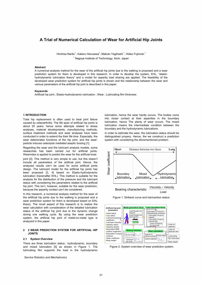
A Trial of Numerical Calculation of Wear for Artificial Hip Joints
Hirohisa Narita 1, Kakeru Harusawa1, Makoto Yagihashi 1, Hideo Fujimoto 1 1 Nagoya Institute of Technology, Aichi, Japan
Abstract A numerical analysis method for the wear of the artificial hip joints due to the walking is proposed and a wear prediction system for them is developed in this research. In order to develop the system, EHL, “elasto-hydrodynamic lubrication theory” and a model for asperity load sharing are applied. The feasibility of the developed wear prediction system for artificial hip joints is shown and the relationship between the wear and various parameters of the artificial hip joint is described in this paper. Keywords: Artificial hip joint ; Elasto-hydrodynamic lubrication ; Wear ; Lubricating film thickness
1 INTRODUCTION Total hip replacement is often used to treat joint failure caused by osteoarthritis. The life span of artificial hip joints is about 20 years; hence some attempts related to stress analyses, material developments, manufacturing methods, surface treatment methods and wear analyses have been conducted in order to extend the their life time. Especially, the wear deteriorates functions of the hip joint, and the wear-particle induces osteolysis mediated aseptic loosing [1].
Regarding the wear and the lubricant analysis models, some researches has been carried out for artificial joints. Wearindex is applied to predict the wear for the artificial knee
joint [2]. This method is very simple to use, but this doesn’t include all parameters of the artificial joint. Hence, the analyzed results can’t be used for some artificial joints design. The lubricant model for the artificial hip joints has been proposed [3, 4] based on Elasto-hydrodynamic lubrication (hereinafter EHL). This method is suitable for the analysis for the distribution of the pressure and the lubricant status with considering the parameters related to the artificial hip joint. This isn’t, however, suitable for the wear prediction, because the asperity contact can’t be considered.
In this research, a numerical analysis method for the wear of the artificial hip joints due to the walking is proposed and a wear prediction system for them is developed based on EHL theory. The novel aspect of this research is to realize the wear calculation with consideration of the detailed lubrication status of the artificial hip joint due to the dynamic change during one walking cycle. By using the wear prediction system, the artificial hip joint of metal-on-metal type is analyzed in this paper.
2 2 WEAR PREDICTION SYSTEM FOR ARTIFICIAL HIP JOINTS
2.1 System Overview There are three lubrication status : hydrodynamic, boundary and mixed lubrication [5] as shown in Figure 1. The lubricating film supports the load in the hydrodynamic
lubrication, hence the wear hardly occurs. The bodies come into closer contact at their asperities in the boundary lubrication, hence The plenty of wear occurs. The mixed lubrication means the intermediate condition between the boundary and the hydrodynamic lubrications
In order to estimate the wear, the lubrication status should be distinguished propery. Hence, the we construct a prediction system with considering the aforementioned problem.
Boundarylubrication
Mixedlubrication
Hydrodynamiclubrication
Wea
r co
effic
ient
Viscosity × Velocity
LoadBearing characteristic
Distance between two faces LongShort
Figure 1: Stribeck curve and lubricantion status .
Head radius Cup radiusLubricant pressure coefficientLubricant viscosityAsperity radiusAsperity densityEquivalent RMS surface roughnessEquivalent Young’s modulusWear coefficientBody weight
Artificial hip jointparameters
-20
-10
0
10
20
30
40
0 0.1 0.2 0.3 0.4 0.5 0.6 0.7 0.8 0.9 1
Rati o of wal king cycle
Angl
e of
hip
join
t [de
g]
-20
-10
0
10
20
30
40
0 0.1 0.2 0.3 0.4 0.5 0.6 0.7 0.8 0.9 1
Rati o of wal king cycle
Angl
e of
hip
join
t [de
g]
0
1
2
3
4
5
6
0 0.2 0.4 0.6 0.8 1
0
1
2
3
4
5
6
0 0.2 0.4 0.6 0.8 1
Hip joint angle
Joint forceper body
Load Equation forasperity
Load Equation forlubricant film
Model generation block Load calculation block
Walking database
Check of balancefor each load
Calculation of load toasperity
Calculation of load tolubricant film
Calculation of minimum lubricating film thickness
Load onasperity
Load onlubricant film
Lubricatingfilm thickness
Wear depth
Velocity ofsliding surfaces
Load to asperity
Wear depth
Wear calculation
0
5
10
15
20
25
30
35
40
45
0 0.2 0.4 0.6 0.8 10
5
10
15
20
25
30
35
40
45
0 0.2 0.4 0.6 0.8 1
Figure 2: System overview of wear prediciton system.
Service Robotics and Mechatronics
21
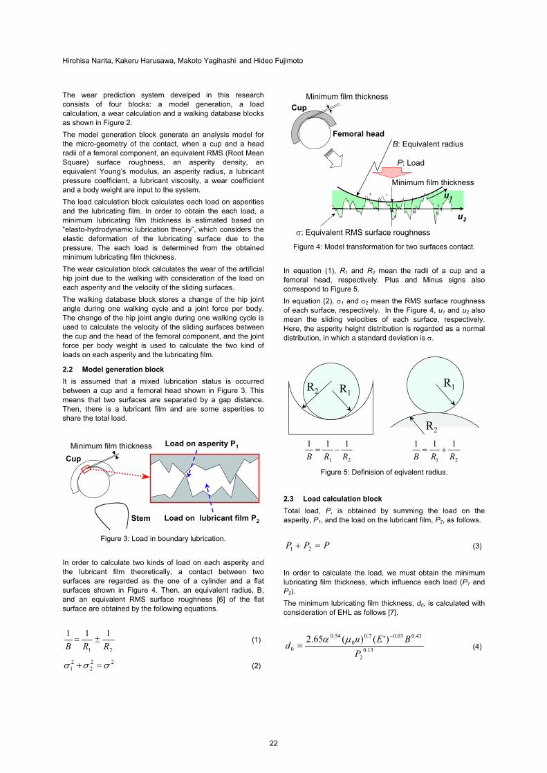
Hirohisa Narita, Kakeru Harusawa, Makoto Yagihashi and Hideo Fujimoto
The wear prediction system develped in this research consists of four blocks: a model generation, a load calculation, a wear calculation and a walking database blocks as shown in Figure 2.
The model generation block generate an analysis model for the micro-geometry of the contact, when a cup and a head radii of a femoral component, an equivalent RMS (Root Mean Square) surface roughness, an asperity density, an equivalent Young’s modulus, an asperity radius, a lubricant pressure coefficient, a lubricant viscosity, a wear coefficient and a body weight are input to the system.
The load calculation block calculates each load on asperities and the lubricating film. In order to obtain the each load, a minimum lubricating film thickness is estimated based on “elasto-hydrodynamic lubrication theory”, which considers the elastic deformation of the lubricating surface due to the pressure. The each load is determined from the obtained minimum lubricating film thickness.
The wear calculation block calculates the wear of the artificial hip joint due to the walking with consideration of the load on each asperity and the velocity of the sliding surfaces.
The walking database block stores a change of the hip joint angle during one walking cycle and a joint force per body. The change of the hip joint angle during one walking cycle is used to calculate the velocity of the sliding surfaces between the cup and the head of the femoral component, and the joint force per body weight is used to calculate the two kind of loads on each asperity and the lubricating film.
2.2 Model generation block It is assumed that a mixed lubrication status is occurred between a cup and a femoral head shown in Figure 3. This means that two surfaces are separated by a gap distance. Then, there is a lubricant film and are some asperities to share the total load.
Load on lubricant film P2
Load on asperity P1
Cup
Stem
Minimum film thickness
Figure 3: Load in boundary lubrication.
In order to calculate two kinds of load on each asperity and the lubricant film theoretically, a contact between two surfaces are regarded as the one of a cylinder and a flat surfaces shown in Figure 4. Then, an equivalent radius, B, and an equivalent RMS surface roughness [6] of the flat surface are obtained by the following equations.
21
111
RRB±= (1)
222
21 σσσ =+ (2)
B: Equivalent radius
u1
P: Load
u2
CupMinimum film thickness
Femoral head
Minimum film thickness
σ: Equivalent RMS surface roughness
Figure 4: Model transformation for two surfaces contact.
In equation (1), R1 and R2 mean the radii of a cup and a femoral head, respectively. Plus and Minus signs also correspond to Figure 5.
In equation (2), σ1 and σ2 mean the RMS surface roughness of each surface, respectively. In the Figure 4, u1 and u2 also mean the sliding velocities of each surface, respectively. Here, the asperity height distribution is regarded as a normal distribution, in which a standard deviation is σ.
R1R2
R1
R2
21
111
RRB−=
21
111
RRB+=
Figure 5: Definision of eqivalent radius.
2.3 Load calculation block Total load, P, is obtained by summing the load on the asperity, P1, and the load on the lubricant film, P2, as follows.
PPP =+ 21 (3)
In order to calculate the load, we must obtain the minimum lubricating film thickness, which influence each load (P1 and P2).
The minimum lubricating film thickness, d0, is calculated with consideration of EHL as follows [7].
13.02
43.003.07.00
54.0
0
)'()(65.2
PBEu
d−
=μα
(4)
22