service manual - ers biomedical pro service... · service manual iso 9001 certified models: pro2c...
TRANSCRIPT
SSEERRVVIICCEEMMAANNUUAALL
ISO 9001 CERTIFIED
Models:PRO2c(Serial Numbers- 1000 and above)
PRO4c(Serial Numbers- 1000 and above)

Vectra™ ProTABLE of CONTENTSForeword . . . . . . . . . . . . . . . . . . . . . . . . . . . . . . . . . . . . . . . .11- Safety Precautions . . . . . . . . . . . . . . . . . . . . . . . . . . . . . . .2
1.1 Precautionary Symbol Definitions . . . . . . . . . . . . . . . . . .21.2 Safety Precautions . . . . . . . . . . . . . . . . . . . . . . . . . . . . .2
2- Theory of Operation . . . . . . . . . . . . . . . . . . . . . . . . . . . .3-42.1 Overview . . . . . . . . . . . . . . . . . . . . . . . . . . . . . . . . . . . .32.2 Power Supply Circuits . . . . . . . . . . . . . . . . . . . . . . . . . .32.3 Control Board . . . . . . . . . . . . . . . . . . . . . . . . . . . . . . . .32.4 Stim Generation Board . . . . . . . . . . . . . . . . . . . . . . . . . .42.5 Ultrasound Board and Applicator . . . . . . . . . . . . . . . . . .42.6 User Interface and Accessories . . . . . . . . . . . . . . . . . . .4
3- Nomenclature . . . . . . . . . . . . . . . . . . . . . . . . . . . . . . . . . . .54- Specifications . . . . . . . . . . . . . . . . . . . . . . . . . . . . . . . . .6-7
4.1 Vectra PRO Physical Specifications . . . . . . . . . . . . . . . .64.2 Vectra PRO Stimulator Output Parameters . . . . . . . . . . .64.3 Vectra PRO Ultrasound Output Parameters . . . . . . . . . .7
5- Troubleshooting . . . . . . . . . . . . . . . . . . . . . . . . . . . . . .8-365.1 Vectra PRO Software Error Messages . . . . . . . . . . . . .8-95.2 Vectra PRO System Testing . . . . . . . . . . . . . . . . . . . . .105.3 Visual Inspection . . . . . . . . . . . . . . . . . . . . . . . . . . . . .115.4 Ground Resistance Test . . . . . . . . . . . . . . . . . . . . . . . .115.5 Leakage Tests . . . . . . . . . . . . . . . . . . . . . . . . . . . . . . .115.6 Unit Startup and Fan Testing . . . . . . . . . . . . . . . . . . . .125.7 Stimulator Tests . . . . . . . . . . . . . . . . . . . . . . . . . . . . . .135.8 VMS™ Mode Test . . . . . . . . . . . . . . . . . . . . . . . . . . . .135.9 Interferential Mode Test . . . . . . . . . . . . . . . . . . . . . . . .145.10 Premodulated Mode Test . . . . . . . . . . . . . . . . . . . . . .145.11 Russian Mode Test . . . . . . . . . . . . . . . . . . . . . . . . . . .155.12 MicroCurrent Mode Test . . . . . . . . . . . . . . . . . . . . . . .165.13 MicroCurrent Probe Mode Test . . . . . . . . . . . . . . . . . .175.14 High Volt Mode Test . . . . . . . . . . . . . . . . . . . . . . . . . .185.15 “Chime” Test . . . . . . . . . . . . . . . . . . . . . . . . . . . . . . .195.16 Ultrasound Tests . . . . . . . . . . . . . . . . . . . . . . . . . . . .205.17 Ultrasound Applicator Identification Test . . . . . . . . . . .205.18 Ultrasound Applicator Output Test . . . . . . . . . . . . . . . .215.19 Ultrasound Duty Cycle Test . . . . . . . . . . . . . . . . . . . .225.20 Combo Operation Test . . . . . . . . . . . . . . . . . . . . . . . .23
5.21 Screen Contrast Test . . . . . . . . . . . . . . . . . . . . . . . . .245.22 Zip Disk Test . . . . . . . . . . . . . . . . . . . . . . . . . . . . . . .245.23 Default Setup Test . . . . . . . . . . . . . . . . . . . . . . . . . . .255.24 Conducting Tests for Channel 3 & 4 of Vectra PRO4 .255.25 Stim Board Main Power Supply Circuit Test . . . . . . . .265.26 Stim Board MicroCurrent Circuit Test . . . . . . . . . . . . .275.27 Stim Board High Volt Circuit Test . . . . . . . . . . . . . .28-295.28 Stim Board Channels 1 and 3 Tests . . . . . . . . . . . . . .305.29 Stim Board Channels 2 and 4 Tests . . . . . . . . . . . . . .315.30 Ultrasound Board Generator Circuit Test . . . . . . . .32-335.31 Ultrasound Board Amplifier Circuit Tests . . . . . . . .34-355.32 Power Distribution Board Tests . . . . . . . . . . . . . . . . . .36
6- Removal & Replacement Procedures . . . . . . . . . . . . .37-436.1 General . . . . . . . . . . . . . . . . . . . . . . . . . . . . . . . . . . . .376.2 Fuse Replacement . . . . . . . . . . . . . . . . . . . . . . . . . . . .376.3 Top & Bottom of Unit . . . . . . . . . . . . . . . . . . . . . . . . . .376.4 Zip Drive Removal & Replacement . . . . . . . . . . . . . . . .386.5 Fan Removal & Replacement . . . . . . . . . . . . . . . . . . . .396.6 Control Board Removal & Replacement . . . . . . . . . . . .406.7 Stim Board #2 (Vectra Pro4) Removal & Replacement .416.8 Stim Board #1 (Vectra Pro 2 & 4)
Removal & Replacement . . . . . . . . . . . . . . . . . . . . . . .426.9 Ultrasound Board Removal & Replacement . . . . . . . . .43
7- Software Installation . . . . . . . . . . . . . . . . . . . . . . . . . .44-457.1 Vectra Pro2 and Pro4 System Software and Upgrades .447.2 Stim Board Software . . . . . . . . . . . . . . . . . . . . . . . . . .45
8- Ultrasound Applicator Calibration . . . . . . . . . . . . . . .46-479- Technical Maintenance . . . . . . . . . . . . . . . . . . . . . . . . . .48Maintenance/Troubleshooting Test Data Sheet . . . . . . . . .49
© 2001 Chattanooga Group, Inc., Chattanooga, Tennessee, USA. Any use of editorial, pictorial or layout composition of this publication without express written consent fromChattanooga Group, Inc. is strictly prohibited. This publication was written, illustrated and prepared for print by Chattanooga Group, Inc. ISO 9001 CERTIFIED


Vectra™ Pro
1
FOREWORDRead, understand and follow the Safety Precautions and information contained in this manual.
This manual contains the necessary safety, and field service information for those Field Service Technicians,approved by Chattanooga Group, Inc., to perform field service on the Vectra Pro units.
At the time of publication the information contained herein was current and up to date. However, due tocontinual technological improvements and increased clinical knowledge in the field of electrotherapy, as well asChattanooga Group, Inc.’s policy of continual improvement, Chattanooga Group, Inc. reserves the right tomake periodic changes and improvements to their equipment and documentation without any obligation on thepart of Chattanooga Group, Inc.
It is the sole responsibility for field technicians to stay informed and trained in the latest technology utilized inthe Vectra Pro units by Chattanooga Group, Inc. From time to time, as significant improvements areincorporated, Service Bulletins will be produced and made available on our web site (www.chattgroup.com) inlieu of reprinting a complete manual prematurely. These Service Bulletins will provide updated serviceinformation and technology improvements to the Vectra Pro for use by approved service technicians.
“Approved Service Technician” Definitions;
1. Level I- Those Field Service Technicians that have successfully completed the minimal training required byChattanooga Group, Inc. in basic service techniques.
2. Level II- Those Field Service Technicians that have successfully completed Level I Training as well asLevel II training as required to perform specific troubleshooting and repair techniques and procedures.
3. Level III- Those Field Service Technicians that have successfully completed Levels I & II Training as well asLevel III Advanced Training as required to perform all necessary Troubleshooting and Repair techniques. The Technician having successfully completed the three levels of training and coupled with experience should have the ability to train other technicians in Level I and Level II Training with the necessary Training Materials from Chattanooga Group, Inc.
4. Temporary- Chattanooga Group, Inc., at its discretion and based on known experience of the technician, may grant a “Temporary Approval” to a field technician for particular troubleshooting and repairof a specific unit requiring immediate attention. This “Temporary Approval” in no fashion acknowledges the training level of a technician as defined above. This “Temporary Approval” isutilized only in unique situations for a specific unit for a specific service technique only and is documented as such.
Due to the complex nature of the technology utilized by Chattanooga Group, Inc., the recommendedtroubleshooting techniques are to determine “Bad Board” and board replacement only. No board componentlevel troubleshooting is recommended nor will information or parts be supplied by Chattanooga Group, Inc. Anyboard component level troubleshooting performed will be at sole risk and liability of the Service Technicianperforming such troubleshooting techniques.
This equipment is to be sold and used only under the prescription and supervision of a licensed medicalpractitioner.
This equipment is to be serviced only by an “Approved Service Technician”.
For Additional Service Contact:Chattanooga Group, Inc.
Electrotherapy/Traction Support DepartmentToll Free: 1-866-864-0598

1.1 Precautionary Symbol DefinitionsThe precautionary instructions found in this manual areindicated by specific symbols. Understand these symbols and their definitions before operating or servicing this equipment. The definitions of these symbols are as follows;A. CAUTION
Text with a “CAUTION” indicator will explain possible Safety infractions that have the potential tocause minor to moderate injury or damage to equipment.
B. WARNING
Text with a “WARNING” indicator will explain possible Safety infractions that will potentially causeserious injury and equipment damage.
C. DANGER
Text with a “DANGER” indicator will explainpossible Safety infractions that are imminently hazardous situations that would result in death or serious injury.
D. EXPLOSION HAZARD
Do not use this equipment in the presence of flammable anesthetics. This symbol is also prominently displayed on the serial number plate of the unit.
E. NOTE:Throughout this manual “NOTE” may be found. The Notes are helpful information to aid in the particular area or function being described.
1.2 Safety PrecautionsRead, understand and follow all safety precautions found in this manual. Below are general safety precautions that must be read and understood before attempting any service techniques on these units. Throughout this manual specific safety precautions willbe found. Read, understand and follow all safety precautions.
• Read, understand and practice the precautionary and operating instructions. Know the limitations and hazards associated with using any electrical stimulation or ultrasound device. Observe the precautionary and operational decals placed on the unit.
• DO NOT operate the Vectra Pro when connected to any unit other than Chattanooga Group, Inc. devices. Do not operate the unit in an environmentof short-wave diathermy use.
• The Ultrasound generator should be routinely checked before each use to determine that all controls function normally; especially that the intensity control does properly adjust the intensity of the ultrasonic power output in a stable manner. Also, determine that the treatment time control does actually terminate ultrasonic power output when the timer reaches zero.
• Use of controls or adjustments or performance of procedures other than those specified herein may result in hazardous exposure to ultrasonic energy.
• DO NOT use sharp objects such as a pencil pointor ballpoint pen to operate the buttons on the control panel as damage may result.
• Operate, transport and store this unit in temperatures between 59 °F and 104 °F (15 °C and 40 °C), with Relative Humidity ranging from30%- 60%.
• Inappropriate handling of, and subjecting the ultrasound applicator to physical abuse, may adversely affect its characteristics.
• Inspect treatment head for cracks, which may allow the ingress of conductive fluid before each use.
• Inspect treatment head cables and associated connectors before each use.
Vectra™ Pro
2
1- SAFETY PRECAUTIONS
! CAUTION
WARNING!
!
! CAUTION
DANGER
2- THEORY of OPERATION2.1 Overview
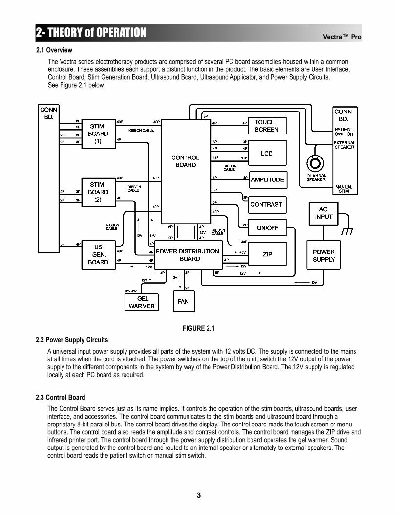
The Vectra series electrotherapy products are comprised of several PC board assemblies housed within a common enclosure. These assemblies each support a distinct function in the product. The basic elements are User Interface, Control Board, Stim Generation Board, Ultrasound Board, Ultrasound Applicator, and Power Supply Circuits.See Figure 2.1 below.
FIGURE 2.12.2 Power Supply Circuits
A universal input power supply provides all parts of the system with 12 volts DC. The supply is connected to the mains at all times when the cord is attached. The power switches on the top of the unit, switch the 12V output of the power supply to the different components in the system by way of the Power Distribution Board. The 12V supply is regulated locally at each PC board as required.
2.3 Control BoardThe Control Board serves just as its name implies. It controls the operation of the stim boards, ultrasound boards, user interface, and accessories. The control board communicates to the stim boards and ultrasound board through a proprietary 8-bit parallel bus. The control board drives the display. The control board reads the touch screen or menu buttons. The control board also reads the amplitude and contrast controls. The control board manages the ZIP drive andinfrared printer port. The control board through the power supply distribution board operates the gel warmer. Sound output is generated by the control board and routed to an internal speaker or alternately to external speakers. The control board reads the patient switch or manual stim switch.
Vectra™ Pro
3
2- THEORY of OPERATION2.4 Stim Generation Board
The stim board creates all muscle stimulation output. Communications to the stim board is via an 8-bit data bus and a dual-port RAM. A processor on the stim board acts on messages passed to it by the control board to set upwaveforms and adjust output amplitude. Information can likewise be passed from the stim board back to the controlboard for monitoring current, GSR mode levels, etc. If the stim board does not respond as expected to a commandfrom the control board, output is stopped and an error message is generated.
2.5 Ultrasound Board and ApplicatorThe ultrasound board generates the 1 or 3.3 MHz output to drive the ultrasound applicator. The ultrasound board is accessed much like an I/O port by the control board. It can provide current and voltage information about the ultrasound output of the board. The calibration data for the applicator is passed through the ultrasound board fromthe applicator up to the control board. By storing the calibration data in the applicator there is no calibration necessary for the ultrasound board and any calibrated Chattanooga Group, Inc. compatible applicator can be attached and operated to provide accurate output.
2.6 User Interface and AccessoriesThe LCD or EL display panel provides the operator visible feedback in the way of menu choices. Pressing the touchscreen or menu buttons makes selections from the menus. The control board interprets these user inputs andresponds accordingly. Audible feedback is given as well for events such as keypresses and end of treatment. The control board accesses the ZIP drive via an IDE interface. Treatment presets can be exported and imported using the disks, as well as giving patients pre-treatment information or the user in-service instruction. The 5 voltsnecessary to operate the drive is generated on the power supply distribution board.The infrared printer port works exclusively with the Jeteye infrared to printer interface unit. This allows printing treatment information to any type of printer the user might have. Due to the large number of printers available, direct printing to infrared-capable printers is not supported.
Vectra™ Pro
4

3- NOMENCLATURE
1
5
432
1098
76
17
16
15
14
13
1211
18
19
3.1 Vectra PRO Physical SpecificationsThe nomenclature graphics below, Figure 3.1, indicatesthe general locations of the exterior components of theVectra Pro.
Know the components and their functions beforeperforming any operation of or service to the Vectra Pro2or Vectra Pro4 units.
FIGURE 3.11. Gel Warmer- Heats coupling gel to approximately
100 °F (37.7 °C) (On/Off only)2. Cooling Fan- Removes excessive heat from component
case3. External Speaker Jack- Allows connection of Optional
External Speakers4. Patient Switch Jack- Allows connection of the Patient
Switch5. Mains Plug- Connect Power Cord to unit6. Touch Screen Control Panel- Set up treatment parameters7. Applicator Storage- Stores two ultrasound applicators8. Microcurrent Probe Port- Connect Microcurrent Probe9. Plug- (Not Used)10. Stim Channels 1&2- Connect Channels 1&2 Lead Wires
11. Stim Channels 3&4- Connect Channels 3&4 Lead Wires**12. Ultrasound Applicator Port- Connect Ultrasound Applicator13. Intensity Control- Adjust treatment intensity levels14. Contrast Control- Adjust Touch Screen Contrast15. Zip Drive- Removable media drive16. OFF- Turn unit OFF17. ON- Turn unit ON18. LED- Indicates Power ON when illuminated19. IR Port- For use with Jeteye accessory to enable printing of
patient treatment information
*Vectra PRO2 and PRO4**Vectra PRO4 Only
Vectra™ Pro
5

PARAMETER INTERFERENTIAL PREMOD RUSSIAN VMS VMS BURST HiVOLT MICROCURRENT
Carrier Freq. 5000Hz 5000Hz 2500Hz - - - 0.1 - 1000Hz
Beat/Burst or Pulse Freq.
0-200 0-200 20~-00 5-200 5-200 1-120 -
Output Method
Pads Pads Pads Pads Pads Pads/Probe Pads/Probe
Sweep Time 15 Seconds 15 Seconds - - - - -
Scan 40% - - - - - -
% Duty Cycle 100% - 10%, 20%, 30%, 40%, 50%
- - - -
Ramp UP/DOWN Time
- - 0.5-5.0 Sec. 0.5-5.0 Sec 0.5-5.0 Sec 0.5-5.0 Sec. 0-1.0 Sec
Cycle Time Sec On/Off
- - 5/5 10/10 10/20 4/12 10/30 10/50
Continuous
5/5 10/10 10/20 4/12 10/30 10/50
Continuous
5/5 10/10 10/20 4/12 10/30 10/50
Continuous
5/5 10/10 10/20 4/12 10/30 10/50
Continuous
-
Polarity - - - - +/- +/- (Alternating)
Amplitude 0-50mA RMS 0-50mA RMS 0-100mA RMS 0-200mA RMS 0-200mA Peak 0-500V Peak 0-995µA Peak
Treatment Time
(Max Minutes)
60 60 60 60 60 99 60
Available On Channels Pro2 (Pro4)
1&2 (1&2, 3&4)
1,2 (1,2,3,4)
1,2 (1,2,3,4)
1,2 (1,2,3,4)
1,2 (1,2,3,4)
2 (2,4)
1 (1,3)
Vectra™ Pro
6
4- SPECIFICATIONS4.1 Vectra PRO Physical Specifications
A. Dimensions1. 16” (406.4mm) Wide
21.5” (546.1mm) Deep8” (203.2mm) High
2. 13.0 lbs (5.9kg) Less Accessories3. Case Material: Polycarbonate Plastic and Steel
B.Outputs1. PRO2
Two Muscle Stimulator OutputsOne Ultrasound Output
2. PRO4Four Muscle Stimulator OutputsOne Ultrasound Output
C. Output Types1. Interferential (Quad-Polar)2. Premodulated (Bi Polar)3. Russian4. VMS (Symmetrical Biphasic)5. HiVolt6. Microcurrent7. Ultrasound
D. Power Input Requirements1. 100-240VAC, 50/60 Hz, 50W
4.2 Vectra PRO Stimulator Output Parameters
Vectra™ Pro
7
4- SPECIFICATIONS
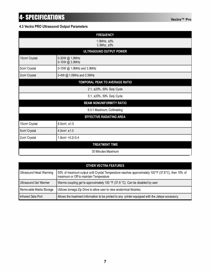
FREQUENCY
1.0MHz, ±5% 3.3Mhz, ±5%
ULTRASOUND OUTPUT POWER
10cm2 Crystal 0-20W @ 1.0MHz 0-10W @ 3.3MHz
5cm2 Crystal 0-10W @ 1.0MHz and 3.3MHz
2cm2 Crystal 0-4W @ 1.0MHz and 3.3MHz
TEMPORAL PEAK TO AVERAGE RATIO
2:1, ±20% , 50% Duty Cycle
5:1, ±20% , 50% Duty Cycle
BEAM NONUNIFORMITY RATIO
6.0:1 Maximum, Collimating
EFFECTIVE RADIATING AREA
10cm2 Crystal 8.5cm2, ±1.5
5cm2 Crystal 4.0cm2, ±1.0
2cm2 Crystal 1.8cm2, +0.2/-0.4
TREATMENT TIME
30 Minutes Maximum
OTHER VECTRA FEATURES
Ultrasound Head Warming 50% of maximum output until Crystal Temperature reaches approximately 100°F (37.8°C), then 10% of maximum or Off to maintain Temperature
Ultrasound Gel Warmer Warms coupling gel to approximately 100 °F (37.8 °C). Can be disabled by user
Removable Media Storage Utilizes Iomega Zip Drive to allow user to view anatomical libraries.
Infrared Data Port Allows the treatment information to be printed to any printer equipped with the Jeteye accessory.
4.3 Vectra PRO Ultrasound Output Parameters
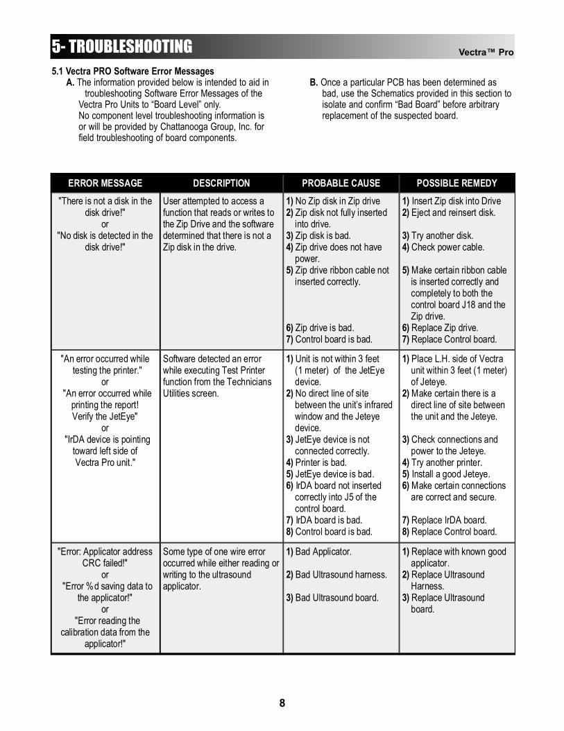
5- TROUBLESHOOTING5.1 Vectra PRO Software Error Messages
A. The information provided below is intended to aid introubleshooting Software Error Messages of the
Vectra Pro Units to “Board Level” only.No component level troubleshooting information is or will be provided by Chattanooga Group, Inc. for field troubleshooting of board components.
B. Once a particular PCB has been determined as bad, use the Schematics provided in this section toisolate and confirm “Bad Board” before arbitrary replacement of the suspected board.
ERROR MESSAGE DESCRIPTION PROBABLE CAUSE POSSIBLE REMEDY "There is not a disk in the
disk drive!" or
"No disk is detected in the disk drive!"
User attempted to access a function that reads or writes to the Zip Drive and the software determined that there is not a Zip disk in the drive.
1) No Zip disk in Zip drive 2) Zip disk not fully inserted into drive. 3) Zip disk is bad. 4) Zip drive does not have power. 5) Zip drive ribbon cable not inserted correctly. 6) Zip drive is bad. 7) Control board is bad.
1) Insert Zip disk into Drive 2) Eject and reinsert disk. 3) Try another disk. 4) Check power cable. 5) Make certain ribbon cable is inserted correctly and completely to both the control board J18 and the Zip drive. 6) Replace Zip drive. 7) Replace Control board.
"An error occurred while testing the printer."
or "An error occurred while
printing the report! Verify the JetEye"
or "IrDA device is pointing
toward left side of Vectra Pro unit."
Software detected an error while executing Test Printer function from the Technicians Utilities screen.
1) Unit is not within 3 feet (1 meter) of the JetEye device. 2) No direct line of site between the unit’s infrared window and the Jeteye device. 3) JetEye device is not connected correctly. 4) Printer is bad. 5) JetEye device is bad. 6) IrDA board not inserted correctly into J5 of the control board. 7) IrDA board is bad. 8) Control board is bad.
1) Place L.H. side of Vectra unit within 3 feet (1 meter) of Jeteye. 2) Make certain there is a direct line of site between the unit and the Jeteye. 3) Check connections and power to the Jeteye. 4) Try another printer. 5) Install a good Jeteye. 6) Make certain connections are correct and secure. 7) Replace IrDA board. 8) Replace Control board.
"Error: Applicator address CRC failed!"
or "Error %d saving data to
the applicator!" or
"Error reading the calibration data from the
applicator!"
Some type of one wire error occurred while either reading or writing to the ultrasound applicator.
1) Bad Applicator. 2) Bad Ultrasound harness. 3) Bad Ultrasound board.
1) Replace with known good applicator. 2) Replace Ultrasound Harness. 3) Replace Ultrasound board.
Vectra™ Pro
8
Vectra™ Pro
9
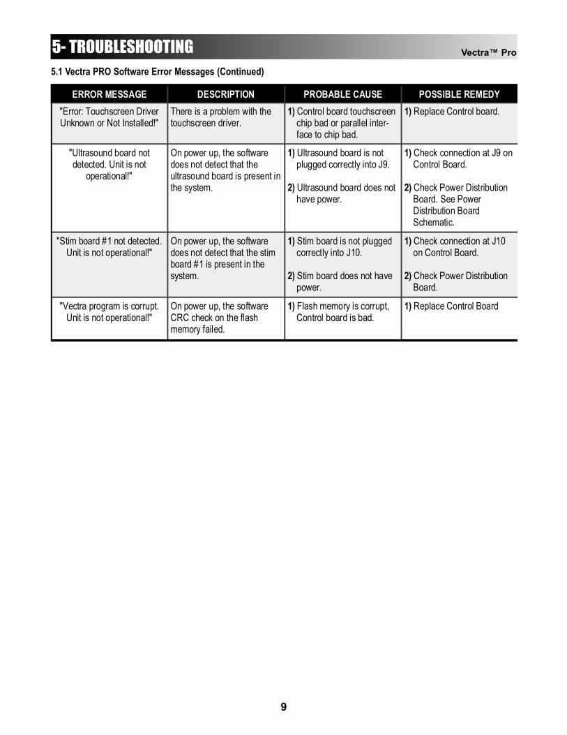
ERROR MESSAGE DESCRIPTION PROBABLE CAUSE POSSIBLE REMEDY "Error: Touchscreen Driver Unknown or Not Installed!"
There is a problem with the touchscreen driver.
1) Control board touchscreen chip bad or parallel inter- face to chip bad.
1) Replace Control board.
"Ultrasound board not detected. Unit is not
operational!"
On power up, the software does not detect that the ultrasound board is present in the system.
1) Ultrasound board is not plugged correctly into J9. 2) Ultrasound board does not have power.
1) Check connection at J9 on Control Board. 2) Check Power Distribution Board. See Power Distribution Board Schematic.
"Stim board #1 not detected. Unit is not operational!"
On power up, the software does not detect that the stim board #1 is present in the system.
1) Stim board is not plugged correctly into J10. 2) Stim board does not have power.
1) Check connection at J10 on Control Board. 2) Check Power Distribution Board.
"Vectra program is corrupt. Unit is not operational!"
On power up, the software CRC check on the flash memory failed.
1) Flash memory is corrupt, Control board is bad.
1) Replace Control Board
5- TROUBLESHOOTING5.1 Vectra PRO Software Error Messages (Continued)
5- TROUBLESHOOTING5.2 Vectra PRO System Testing
A. General1. The following information is intended to aid in
troubleshooting the major components of the Vectra Pro Units to “Board Level” only. These tests are OEM standard testing procedures and methods used at the factory before shipment of any Vectra Pro unit.
2. Due to the complex nature of the technology utilized by Chattanooga Group, Inc., the recommended troubleshooting techniques are to determine “Bad Board” and board replacement only. No board component level troubleshooting is recommended nor will information or parts be supplied by Chattanooga Group, Inc. Anyboard component level troubleshooting performed will be at sole risk and liability ofthe Service Technician performing such troubleshooting techniques.
3. Once a particular PC Board has been determinedas bad, use the Schematics provided in this section to isolate and confirm “Bad Board” beforearbitrary replacement of the suspected board.
4. Stimulator Board(s);a) Stim Board #1 controls Channels 1 & 2.b) Stim Board #2 controls Channels 3 & 4.
B. Special Tools, Fixtures & Materials Required1. Certain tests require the use of special Tools
and/or Fixtures. These will be listed at the particular test where they are required. Testing with any other special tool or fixture other than those stated could give erroneous readings or test results. Always perform the tests exactly as stated to ensure accurate results.
2. Any special tools or fixtures required can be obtained through Chattanooga Group, Inc., Service Department.
3. Scope and other standard test equipment settings will be listed for each test performed to aid in performing the test to OEM standards and ensure proper readings.
4. The troubleshooting and repair of the Vectra Pro units, should be performed only by authorized technicians trained and certified by Chattanooga Group, Inc.
C. Equipment Required1. Oscilloscope and Probes2. 650 Ohm load for outputs3. 10k Load for output4. Digital Multimeter
5. Microcurrent Probe (Vectra Accessory)6. Patient Switch (Vectra Accessory)7. Manual Stim Switch (Vectra Optional Accessory)8. Ultrasound Applicators (Vectra Accessories)9. Dielectric Withstand (Hi-Pot) and ground
resistance tester.NOTE:Adjust Dielectric Withstand tester to indicate fault with120k Ohm Load across the output when at specified testvoltage.
10. Ohmic Instruments UPM DT 10 Ultrasound Power Meter.
11. Degassed Water (<5ppm) for Ultrasound Power Meter.
a) Recipe(s) for Degassed Water1) Boil Distilled Water for 30 minutes. Place
water in a nonporous container and immediately cover with cellophane. Allow to cool to room temperature of approximately 70°F (21°C). May be refrigerated to aid cooling time.
2) Bring Distilled Water to a boil. Place the container under vacuum for 5 to 10 minutes.
12. Dissolved Oxygen Test Kit. Used to test oxygen level of degassed water.
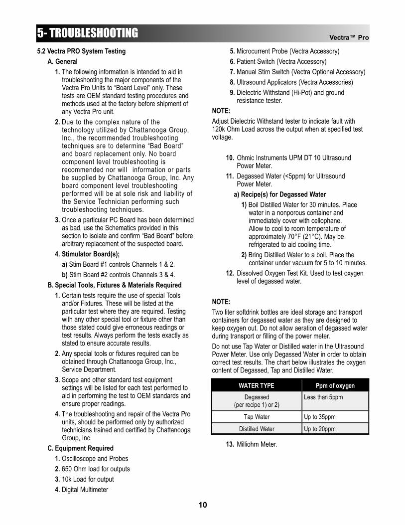
NOTE:Two liter softdrink bottles are ideal storage and transportcontainers for degassed water as they are designed tokeep oxygen out. Do not allow aeration of degassed waterduring transport or filling of the power meter.Do not use Tap Water or Distilled water in the UltrasoundPower Meter. Use only Degassed Water in order to obtaincorrect test results. The chart below illustrates the oxygencontent of Degassed, Tap and Distilled Water.
13. Milliohm Meter.
WATER TYPE Ppm of oxygen Degassed
(per recipe 1) or 2) Less than 5ppm
Tap Water Up to 35ppm
Distilled Water Up to 20ppm
Vectra™ Pro
10
Vectra™ Pro
11
5- TROUBLESHOOTING5.3 Visual Inspection
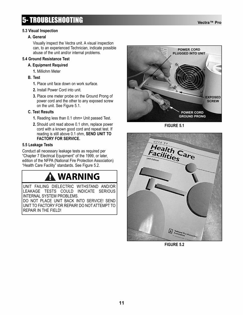
A. GeneralVisually inspect the Vectra unit. A visual inspection can, to an experienced Technician, indicate possibleabuse of the unit and/or internal problems.
5.4 Ground Resistance TestA. Equipment Required
1. Milliohm MeterB. Test
1. Place unit face down on work surface.2. Install Power Cord into unit.3. Place one meter probe on the Ground Prong of
power cord and the other to any exposed screw on the unit. See Figure 5.1.
C. Test Results1. Reading less than 0.1 ohm= Unit passed Test.2. Should unit read above 0.1 ohm, replace power
cord with a known good cord and repeat test. If reading is still above 0.1 ohm, SEND UNIT TO FACTORY FOR SERVICE.
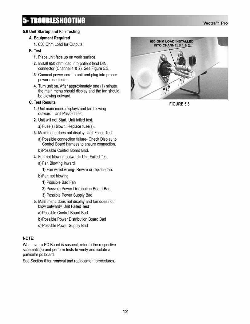
5.5 Leakage TestsConduct all necessary leakage tests as required per“Chapter 7 Electrical Equipment” of the 1999, or later,edition of the NFPA (National Fire Protection Association)“Health Care Facility” standards. See Figure 5.2.
WARNING!UNIT FAILING DIELECTRIC WITHSTAND AND/ORLEAKAGE TESTS COULD INDICATE SERIOUSINTERNAL SYSTEM PROBLEMS.DO NOT PLACE UNIT BACK INTO SERVICE! SENDUNIT TO FACTORY FOR REPAIR! DO NOT ATTEMPT TOREPAIR IN THE FIELD!
EXPOSEDSCREW
POWER CORDGROUND PRONG
POWER CORDPLUGGED INTO UNIT
FIGURE 5.1
FIGURE 5.2
Vectra™ Pro
12
5- TROUBLESHOOTING5.6 Unit Startup and Fan Testing
A. Equipment Required1. 650 Ohm Load for Outputs
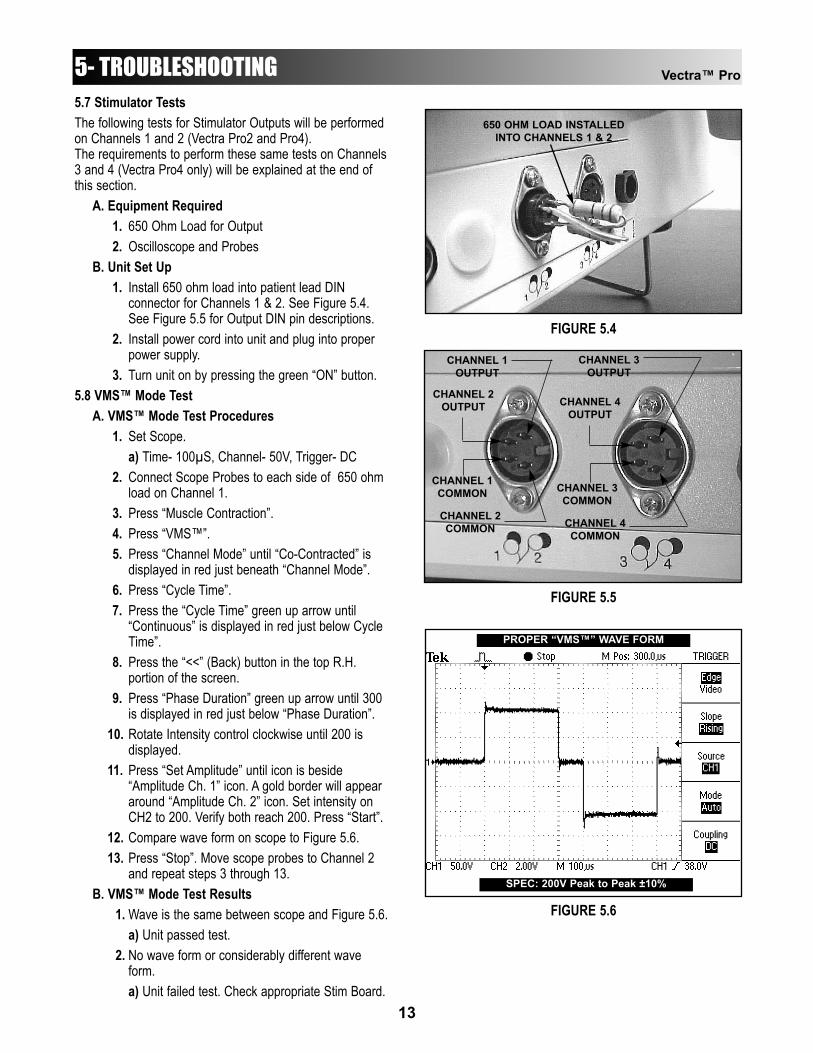
B. Test1. Place unit face up on work surface.2. Install 650 ohm load into patient lead DIN
connector (Channel 1 & 2). See Figure 5.3.3. Connect power cord to unit and plug into proper
power receptacle.4. Turn unit on. After approximately one (1) minute
the main menu should display and the fan shouldbe blowing outward.
C. Test Results1. Unit main menu displays and fan blowing
outward= Unit Passed Test.2. Unit will not Start. Unit failed test.
a) Fuse(s) blown. Replace fuse(s).3. Main menu does not display=Unit Failed Test
a) Possible connection failure- Check Display to Control Board harness to ensure connection.
b)Possible Control Board Bad.4. Fan not blowing outward= Unit Failed Test
a) Fan Blowing Inward1) Fan wired wrong- Rewire or replace fan.
b)Fan not blowing1) Possible Bad Fan2) Possible Power Distribution Board Bad.3) Possible Power Supply Bad
5. Main menu does not display and fan does not blow outward= Unit Failed Testa) Possible Control Board Bad.b)Possible Power Distribution Board Badc) Possible Power Supply Bad
NOTE:Whenever a PC Board is suspect, refer to the respectiveschematic(s) and perform tests to verify and isolate aparticular pc board.See Section 6 for removal and replacement procedures.
FIGURE 5.3
650 OHM LOAD INSTALLEDINTO CHANNELS 1 & 2
Vectra™ Pro
13
5- TROUBLESHOOTING5.7 Stimulator TestsThe following tests for Stimulator Outputs will be performedon Channels 1 and 2 (Vectra Pro2 and Pro4).The requirements to perform these same tests on Channels3 and 4 (Vectra Pro4 only) will be explained at the end ofthis section.
A. Equipment Required1. 650 Ohm Load for Output2. Oscilloscope and Probes
B. Unit Set Up1. Install 650 ohm load into patient lead DIN
connector for Channels 1 & 2. See Figure 5.4.See Figure 5.5 for Output DIN pin descriptions.
2. Install power cord into unit and plug into proper power supply.
3. Turn unit on by pressing the green “ON” button.5.8 VMS™ Mode Test
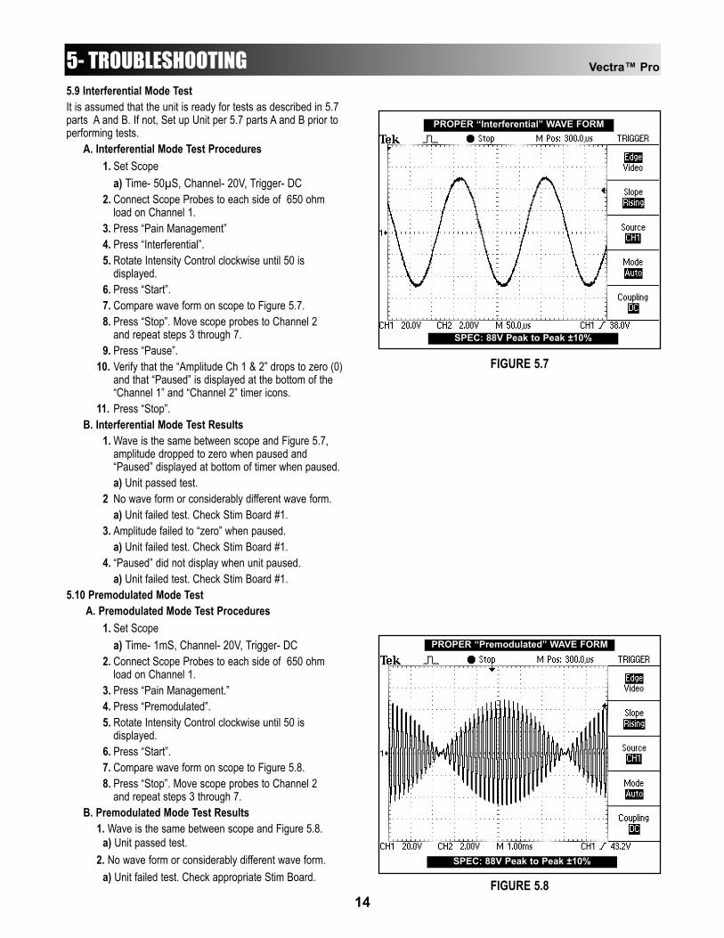
A. VMS™ Mode Test Procedures1. Set Scope.
a) Time- 100µS, Channel- 50V, Trigger- DC2. Connect Scope Probes to each side of 650 ohm
load on Channel 1.3. Press “Muscle Contraction”.4. Press “VMS™”.5. Press “Channel Mode” until “Co-Contracted” is
displayed in red just beneath “Channel Mode”.6. Press “Cycle Time”.7. Press the “Cycle Time” green up arrow until
“Continuous” is displayed in red just below Cycle Time”.
8. Press the “<<” (Back) button in the top R.H. portion of the screen.
9. Press “Phase Duration” green up arrow until 300 is displayed in red just below “Phase Duration”.
10. Rotate Intensity control clockwise until 200 is displayed.
11. Press “Set Amplitude” until icon is beside “Amplitude Ch. 1” icon. A gold border will appear around “Amplitude Ch. 2” icon. Set intensity on CH2 to 200. Verify both reach 200. Press “Start”.
12. Compare wave form on scope to Figure 5.6.13. Press “Stop”. Move scope probes to Channel 2
and repeat steps 3 through 13.B. VMS™ Mode Test Results
1. Wave is the same between scope and Figure 5.6.a) Unit passed test.
2. No wave form or considerably different wave form.a) Unit failed test. Check appropriate Stim Board.
FIGURE 5.4
650 OHM LOAD INSTALLEDINTO CHANNELS 1 & 2
CHANNEL 1OUTPUT
CHANNEL 3OUTPUT
CHANNEL 2OUTPUT CHANNEL 4
OUTPUT
CHANNEL 1COMMON
CHANNEL 2COMMON
CHANNEL 3COMMON
CHANNEL 4COMMON
FIGURE 5.5
FIGURE 5.6
PROPER “VMS™” WAVE FORM
SPEC: 200V Peak to Peak ±10%
Vectra™ Pro
14
5- TROUBLESHOOTING5.9 Interferential Mode TestIt is assumed that the unit is ready for tests as described in 5.7parts A and B. If not, Set up Unit per 5.7 parts A and B prior toperforming tests.
A. Interferential Mode Test Procedures1. Set Scope
a) Time- 50µS, Channel- 20V, Trigger- DC2. Connect Scope Probes to each side of 650 ohm
load on Channel 1.3. Press “Pain Management”4. Press “Interferential”.5. Rotate Intensity Control clockwise until 50 is
displayed.6. Press “Start”.7. Compare wave form on scope to Figure 5.7.8. Press “Stop”. Move scope probes to Channel 2
and repeat steps 3 through 7.9. Press “Pause”.
10. Verify that the “Amplitude Ch 1 & 2” drops to zero (0) and that “Paused” is displayed at the bottom of the “Channel 1” and “Channel 2” timer icons.
11. Press “Stop”.B. Interferential Mode Test Results
1. Wave is the same between scope and Figure 5.7, amplitude dropped to zero when paused and “Paused” displayed at bottom of timer when paused.a) Unit passed test.
2 No wave form or considerably different wave form.a) Unit failed test. Check Stim Board #1.
3. Amplitude failed to “zero” when paused.a) Unit failed test. Check Stim Board #1.
4. “Paused” did not display when unit paused.a) Unit failed test. Check Stim Board #1.
5.10 Premodulated Mode TestA. Premodulated Mode Test Procedures
1. Set Scopea) Time- 1mS, Channel- 20V, Trigger- DC
2. Connect Scope Probes to each side of 650 ohm load on Channel 1.
3. Press “Pain Management.”4. Press “Premodulated”.5. Rotate Intensity Control clockwise until 50 is
displayed.6. Press “Start”.7. Compare wave form on scope to Figure 5.8.8. Press “Stop”. Move scope probes to Channel 2
and repeat steps 3 through 7.B. Premodulated Mode Test Results
1. Wave is the same between scope and Figure 5.8.a) Unit passed test.
2. No wave form or considerably different wave form.a) Unit failed test. Check appropriate Stim Board.
FIGURE 5.7
PROPER “Interferential” WAVE FORM
SPEC: 88V Peak to Peak ±10%
FIGURE 5.8
PROPER “Premodulated” WAVE FORM
SPEC: 88V Peak to Peak ±10%
Vectra™ Pro
15
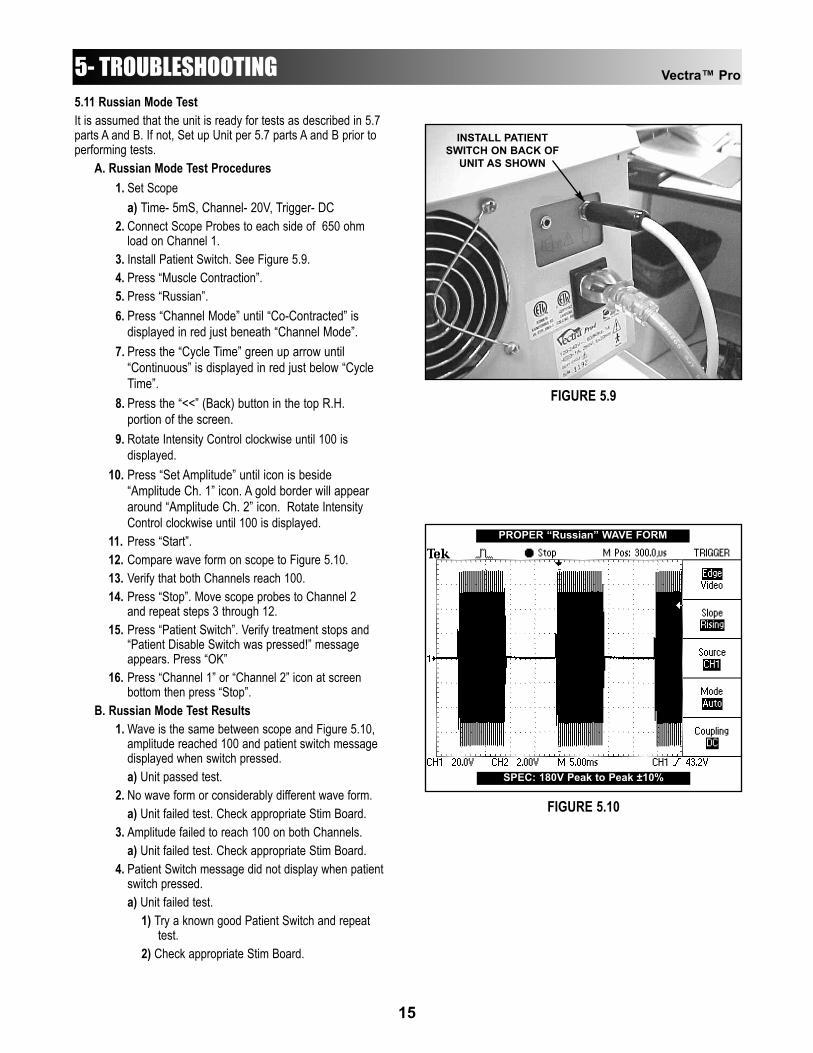
5- TROUBLESHOOTING5.11 Russian Mode TestIt is assumed that the unit is ready for tests as described in 5.7parts A and B. If not, Set up Unit per 5.7 parts A and B prior toperforming tests.
A. Russian Mode Test Procedures1. Set Scope
a) Time- 5mS, Channel- 20V, Trigger- DC2. Connect Scope Probes to each side of 650 ohm
load on Channel 1.3. Install Patient Switch. See Figure 5.9.4. Press “Muscle Contraction”.5. Press “Russian”.6. Press “Channel Mode” until “Co-Contracted” is
displayed in red just beneath “Channel Mode”.7. Press the “Cycle Time” green up arrow until
“Continuous” is displayed in red just below “Cycle Time”.
8. Press the “<<” (Back) button in the top R.H. portion of the screen.
9. Rotate Intensity Control clockwise until 100 is displayed.
10. Press “Set Amplitude” until icon is beside “Amplitude Ch. 1” icon. A gold border will appear around “Amplitude Ch. 2” icon. Rotate Intensity Control clockwise until 100 is displayed.
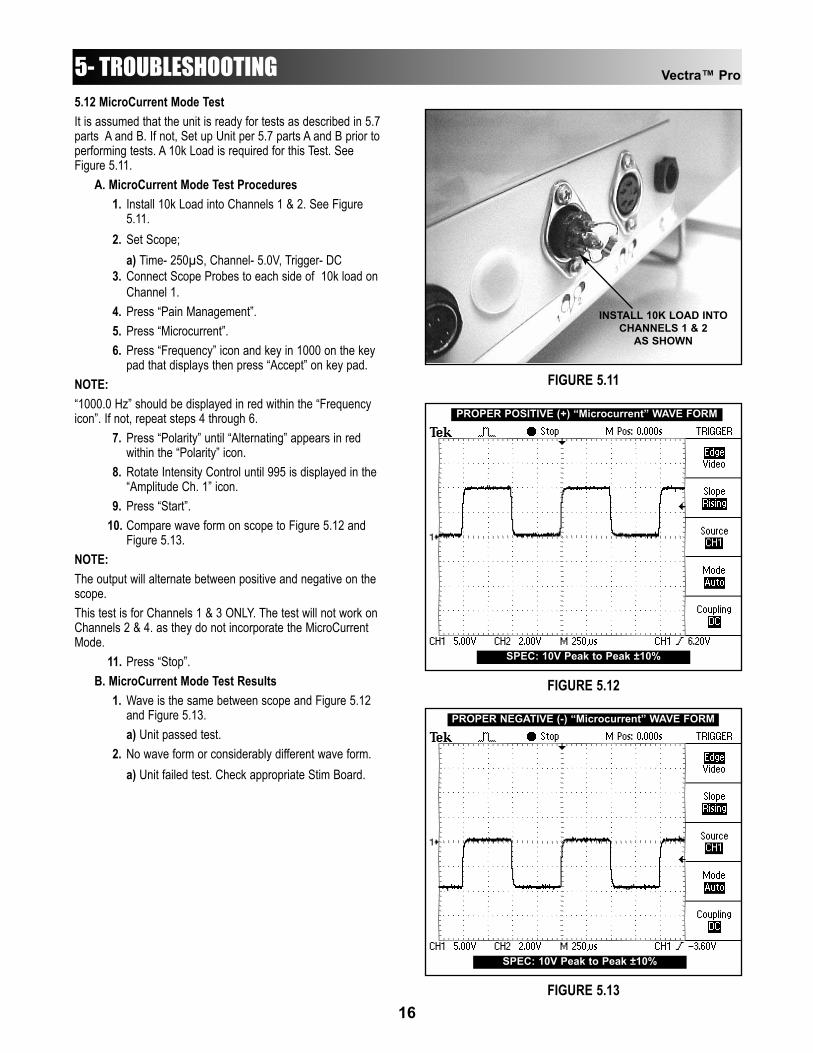
11. Press “Start”.12. Compare wave form on scope to Figure 5.10.13. Verify that both Channels reach 100.14. Press “Stop”. Move scope probes to Channel 2
and repeat steps 3 through 12.15. Press “Patient Switch”. Verify treatment stops and
“Patient Disable Switch was pressed!” message appears. Press “OK”
16. Press “Channel 1” or “Channel 2” icon at screen bottom then press “Stop”.
B. Russian Mode Test Results1. Wave is the same between scope and Figure 5.10,
amplitude reached 100 and patient switch message displayed when switch pressed.a) Unit passed test.
2. No wave form or considerably different wave form.a) Unit failed test. Check appropriate Stim Board.
3. Amplitude failed to reach 100 on both Channels.a) Unit failed test. Check appropriate Stim Board.
4. Patient Switch message did not display when patient switch pressed.a) Unit failed test.
1) Try a known good Patient Switch and repeat test.
2) Check appropriate Stim Board.
FIGURE 5.9
FIGURE 5.10
PROPER “Russian” WAVE FORM
SPEC: 180V Peak to Peak ±10%
INSTALL PATIENTSWITCH ON BACK OF
UNIT AS SHOWN
Vectra™ Pro
16
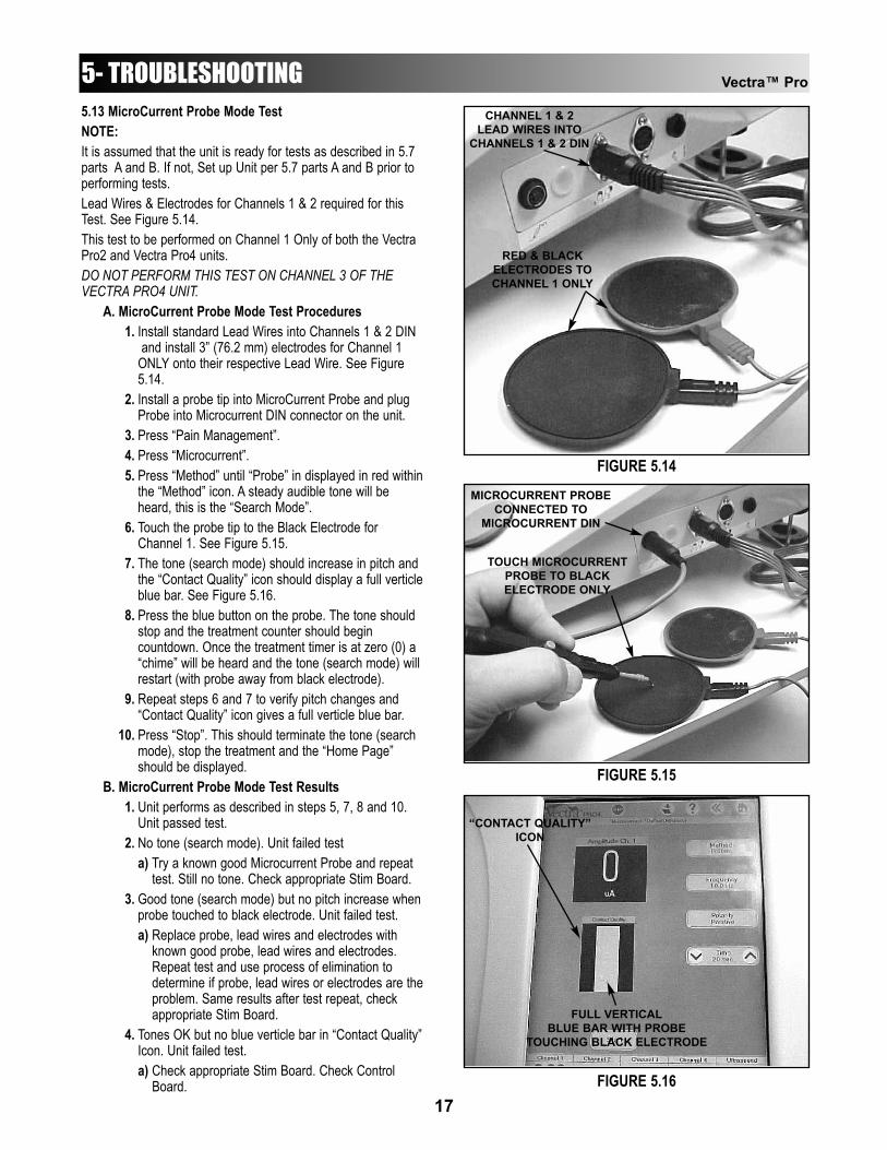
5- TROUBLESHOOTING5.12 MicroCurrent Mode TestIt is assumed that the unit is ready for tests as described in 5.7parts A and B. If not, Set up Unit per 5.7 parts A and B prior toperforming tests. A 10k Load is required for this Test. SeeFigure 5.11.
A. MicroCurrent Mode Test Procedures1. Install 10k Load into Channels 1 & 2. See Figure
5.11.2. Set Scope;
a) Time- 250µS, Channel- 5.0V, Trigger- DC3. Connect Scope Probes to each side of 10k load on
Channel 1.4. Press “Pain Management”.5. Press “Microcurrent”.6. Press “Frequency” icon and key in 1000 on the key
pad that displays then press “Accept” on key pad.NOTE:“1000.0 Hz” should be displayed in red within the “Frequencyicon”. If not, repeat steps 4 through 6.
7. Press “Polarity” until “Alternating” appears in red within the “Polarity” icon.
8. Rotate Intensity Control until 995 is displayed in the “Amplitude Ch. 1” icon.
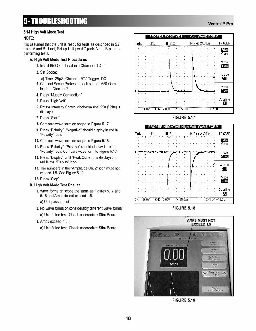
9. Press “Start”.10. Compare wave form on scope to Figure 5.12 and
Figure 5.13.NOTE:The output will alternate between positive and negative on thescope.This test is for Channels 1 & 3 ONLY. The test will not work onChannels 2 & 4. as they do not incorporate the MicroCurrentMode.
11. Press “Stop”.B. MicroCurrent Mode Test Results
1. Wave is the same between scope and Figure 5.12 and Figure 5.13.a) Unit passed test.
2. No wave form or considerably different wave form.a) Unit failed test. Check appropriate Stim Board.
FIGURE 5.11
INSTALL 10K LOAD INTOCHANNELS 1 & 2
AS SHOWN
FIGURE 5.12
PROPER POSITIVE (+) “Microcurrent” WAVE FORM
SPEC: 10V Peak to Peak ±10%
FIGURE 5.13
PROPER NEGATIVE (-) “Microcurrent” WAVE FORM
SPEC: 10V Peak to Peak ±10%
Vectra™ Pro
17
5- TROUBLESHOOTING5.13 MicroCurrent Probe Mode TestNOTE:It is assumed that the unit is ready for tests as described in 5.7parts A and B. If not, Set up Unit per 5.7 parts A and B prior toperforming tests.Lead Wires & Electrodes for Channels 1 & 2 required for thisTest. See Figure 5.14.This test to be performed on Channel 1 Only of both the VectraPro2 and Vectra Pro4 units.DO NOT PERFORM THIS TEST ON CHANNEL 3 OF THEVECTRA PRO4 UNIT.
A. MicroCurrent Probe Mode Test Procedures1. Install standard Lead Wires into Channels 1 & 2 DIN
and install 3” (76.2 mm) electrodes for Channel 1 ONLY onto their respective Lead Wire. See Figure 5.14.
2. Install a probe tip into MicroCurrent Probe and plug Probe into Microcurrent DIN connector on the unit.
3. Press “Pain Management”.4. Press “Microcurrent”.5. Press “Method” until “Probe” in displayed in red within
the “Method” icon. A steady audible tone will be heard, this is the “Search Mode”.
6. Touch the probe tip to the Black Electrode for Channel 1. See Figure 5.15.
7. The tone (search mode) should increase in pitch and the “Contact Quality” icon should display a full verticleblue bar. See Figure 5.16.
8. Press the blue button on the probe. The tone should stop and the treatment counter should begin countdown. Once the treatment timer is at zero (0) a “chime” will be heard and the tone (search mode) will restart (with probe away from black electrode).
9. Repeat steps 6 and 7 to verify pitch changes and “Contact Quality” icon gives a full verticle blue bar.
10. Press “Stop”. This should terminate the tone (search mode), stop the treatment and the “Home Page” should be displayed.
B. MicroCurrent Probe Mode Test Results1. Unit performs as described in steps 5, 7, 8 and 10.
Unit passed test.2. No tone (search mode). Unit failed test
a) Try a known good Microcurrent Probe and repeat test. Still no tone. Check appropriate Stim Board.
3. Good tone (search mode) but no pitch increase when probe touched to black electrode. Unit failed test.a) Replace probe, lead wires and electrodes with
known good probe, lead wires and electrodes. Repeat test and use process of elimination to determine if probe, lead wires or electrodes are theproblem. Same results after test repeat, check appropriate Stim Board.
4. Tones OK but no blue verticle bar in “Contact Quality”Icon. Unit failed test.a) Check appropriate Stim Board. Check Control
Board.
FIGURE 5.14
FIGURE 5.15
FIGURE 5.16
CHANNEL 1 & 2LEAD WIRES INTO
CHANNELS 1 & 2 DIN
RED & BLACKELECTRODES TOCHANNEL 1 ONLY
MICROCURRENT PROBECONNECTED TO
MICROCURRENT DIN
TOUCH MICROCURRENTPROBE TO BLACKELECTRODE ONLY
“CONTACT QUALITY”ICON
FULL VERTICALBLUE BAR WITH PROBE
TOUCHING BLACK ELECTRODE
Vectra™ Pro
18
5- TROUBLESHOOTING5.14 High Volt Mode TestNOTE:It is assumed that the unit is ready for tests as described in 5.7parts A and B. If not, Set up Unit per 5.7 parts A and B prior toperforming tests.
A. High Volt Mode Test Procedures1. Install 650 Ohm Load into Channels 1 & 2.2. Set Scope;
a) Time- 25µS, Channel- 50V, Trigger- DC3. Connect Scope Probes to each side of 650 Ohm
load on Channel 2.4. Press “Muscle Contraction”.5. Press “High Volt”.6. Rotate Intensity Control clockwise until 250 (Volts) is
displayed.7. Press “Start”.8. Compare wave form on scope to Figure 5.17.9. Press “Polarity”. “Negative” should display in red in
“Polarity” icon.10. Compare wave form on scope to Figure 5.18.11. Press “Polarity”. “Positive” should display in red in
“Polarity” icon. Compare wave form to Figure 5.17.12. Press “Display” until “Peak Current” is displayed in
red in the “Display” icon.13. The numbers in the “Amplitude Ch. 2” icon must not
exceed 1.5. See Figure 5.19.12. Press “Stop”.
B. High Volt Mode Test Results1. Wave forms on scope the same as Figures 5.17 and
5.18 and Amps do not exceed 1.5.a) Unit passed test.
2. No wave forms or considerably different wave forms.a) Unit failed test. Check appropriate Stim Board.
3. Amps exceed 1.5.a) Unit failed test. Check appropriate Stim Board.
PROPER POSITIVE High Volt WAVE FORM
FIGURE 5.17
PROPER NEGATIVE High Volt WAVE FORM
FIGURE 5.18
FIGURE 5.19
AMPS MUST NOTEXCEED 1.5
Vectra™ Pro
19
5- TROUBLESHOOTING5.15 “Chime” Test
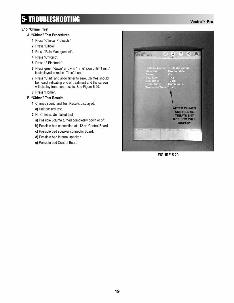
A. “Chime” Test Procedures1. Press “Clinical Protocols”.2. Press “Elbow”3. Press “Pain Management”.4. Press “Chronic”.5. Press “2 Electrode”.6. Press green “down” arrow in “Time” icon until “1 min.”
is displayed in red in “Time” icon.7. Press “Start” and allow timer to zero. Chimes should
be heard indicating end of treatment and the screen will display treatment results. See Figure 5.20.
8. Press “Home”.B. “Chime” Test Results
1. Chimes sound and Test Results displayed.a) Unit passed test.
2. No Chimes. Unit failed testa) Possible volume turned completely down or off.b) Possible bad connection at J12 on Control Board.c) Possible bad speaker connector board.d) Possible bad internal speaker.e) Possible bad Control Board.
AFTER CHIMESARE HEARD,TREATMENT
RESULTS WILLDISPLAY
FIGURE 5.20
5.16 Ultrasound TestsA. Equipment Required
1. Degassed Water. Refer to page 10 for Degassed Water Recipes.
2. Ohmic Instruments UPM DT 10 Ultrasound Power Meter.
3. Dissolved Oxygen Test Kit. Used to test oxygen level of degassed water.
5.17 Ultrasound Applicator Identification TestNOTE:Use any Vectra Pro Ultrasound Applicator for this test.
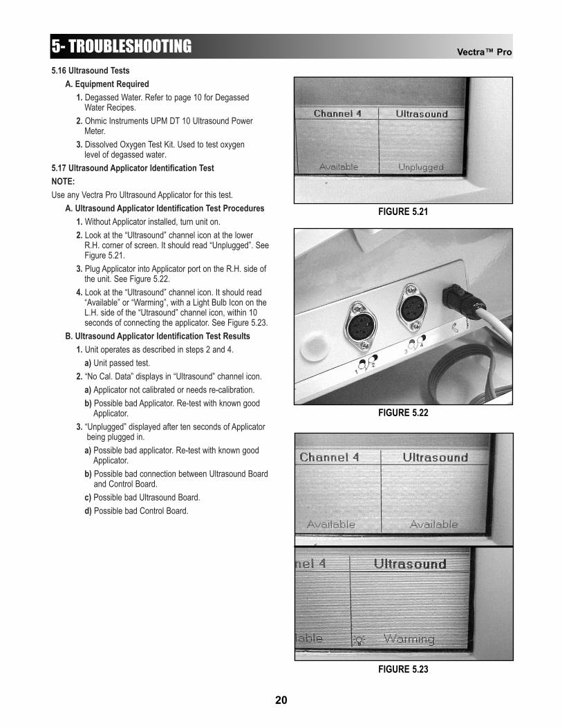
A. Ultrasound Applicator Identification Test Procedures1. Without Applicator installed, turn unit on.2. Look at the “Ultrasound” channel icon at the lower
R.H. corner of screen. It should read “Unplugged”. SeeFigure 5.21.
3. Plug Applicator into Applicator port on the R.H. side of the unit. See Figure 5.22.
4. Look at the “Ultrasound” channel icon. It should read “Available” or “Warming”, with a Light Bulb Icon on the L.H. side of the “Utrasound” channel icon, within 10 seconds of connecting the applicator. See Figure 5.23.
B. Ultrasound Applicator Identification Test Results1. Unit operates as described in steps 2 and 4.
a) Unit passed test.2. “No Cal. Data” displays in “Ultrasound” channel icon.
a) Applicator not calibrated or needs re-calibration.b) Possible bad Applicator. Re-test with known good
Applicator.3. “Unplugged” displayed after ten seconds of Applicator
being plugged in.a) Possible bad applicator. Re-test with known good
Applicator.b) Possible bad connection between Ultrasound Board
and Control Board.c) Possible bad Ultrasound Board.d) Possible bad Control Board.
Vectra™ Pro
20
5- TROUBLESHOOTING
FIGURE 5.21
FIGURE 5.22
FIGURE 5.23
Vectra™ Pro
21
5.18 Ultrasound Applicator Output TestPerform this test using all available Applicators for the unit beingtested.
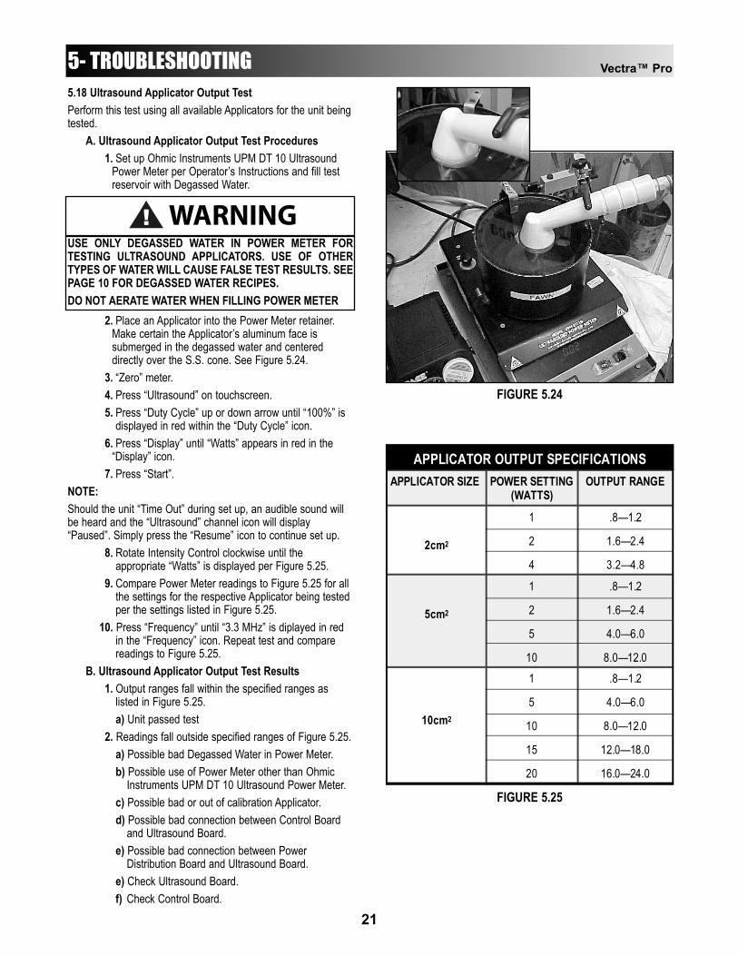
A. Ultrasound Applicator Output Test Procedures1. Set up Ohmic Instruments UPM DT 10 Ultrasound
Power Meter per Operator’s Instructions and fill test reservoir with Degassed Water.
2. Place an Applicator into the Power Meter retainer. Make certain the Applicator’s aluminum face is submerged in the degassed water and centered directly over the S.S. cone. See Figure 5.24.
3. “Zero” meter.4. Press “Ultrasound” on touchscreen.5. Press “Duty Cycle” up or down arrow until “100%” is
displayed in red within the “Duty Cycle” icon.6. Press “Display” until “Watts” appears in red in the
“Display” icon.7. Press “Start”.
NOTE:Should the unit “Time Out” during set up, an audible sound willbe heard and the “Ultrasound” channel icon will display“Paused”. Simply press the “Resume” icon to continue set up.
8. Rotate Intensity Control clockwise until the appropriate “Watts” is displayed per Figure 5.25.
9. Compare Power Meter readings to Figure 5.25 for all the settings for the respective Applicator being tested per the settings listed in Figure 5.25.
10. Press “Frequency” until “3.3 MHz” is diplayed in red in the “Frequency” icon. Repeat test and compare readings to Figure 5.25.
B. Ultrasound Applicator Output Test Results1. Output ranges fall within the specified ranges as
listed in Figure 5.25.a) Unit passed test
2. Readings fall outside specified ranges of Figure 5.25.a) Possible bad Degassed Water in Power Meter.b) Possible use of Power Meter other than Ohmic
Instruments UPM DT 10 Ultrasound Power Meter.c) Possible bad or out of calibration Applicator.d) Possible bad connection between Control Board
and Ultrasound Board.e) Possible bad connection between Power
Distribution Board and Ultrasound Board.e) Check Ultrasound Board.f) Check Control Board.
5- TROUBLESHOOTING
WARNING!USE ONLY DEGASSED WATER IN POWER METER FORTESTING ULTRASOUND APPLICATORS. USE OF OTHERTYPES OF WATER WILL CAUSE FALSE TEST RESULTS. SEEPAGE 10 FOR DEGASSED WATER RECIPES.DO NOT AERATE WATER WHEN FILLING POWER METER
APPLICATOR SIZE POWER SETTING (WATTS)
OUTPUT RANGE
2cm2
1
2
4
.8—1.2
1.6—2.4
3.2—4.8
5cm2
1
2
5
10
.8—1.2
1.6—2.4
4.0—6.0
8.0—12.0
10cm2
1
5
10
15
20
.8—1.2
4.0—6.0
8.0—12.0
12.0—18.0
16.0—24.0
APPLICATOR OUTPUT SPECIFICATIONS
FIGURE 5.24
FIGURE 5.25

Vectra™ Pro
22
5- TROUBLESHOOTING5.19 Ultrasound Duty Cycle TestThis test is performed using only the 5cm2 Applicator.
A. Ultrasound Duty Cycle Test Procedures1. Set up Ohmic Instruments UPM DT 10 Ultrasound
Power Meter per Operator’s Instructions and fill test reservoir with Degassed Water.
2. Place the Applicator into the Power Meter retainer. Make certain the Applicator’s aluminum face is submerged in the degassed water and centered directly over the S.S. cone. See Figure 5.26.
3. “Zero” meter.4. Press “Ultrasound” on touchscreen.5. Press “Display” until “Watts” appears in red in the
“Display” icon.6. Press “Start”.
NOTE:Should the unit “Time Out” during set up, an audible sound willbe heard and the “Ultrasound” channel icon will display“Paused”. Simply press the “Resume” icon to continue set up.
7. Press green down arrow in “Duty Cycle” icon until “10%” is displayed in red in the “Duty Cycle” icon.
8. Compare Power Meter readings to Figure 5.27 for each of the following “Duty Cycle” settings listed in thechart.
9. Press “Frequency” until “3.3 MHz” is displayed in red in the “Frequency” icon. Repeat test and compare readings to Figure 5.27.
B. Ultrasound Duty Cycle Test Results1. Duty Cycles fall within the specified ranges as listed in
Figure 5.27.a) Unit passed test
2. Readings fall outside specified ranges of Figure 5.27.a) Possible bad Degassed Water in Power Meter.b) Possible use of Power Meter other than Ohmic
Instruments UPM DT 10 Ultrasound Power Meter.c) Possible bad or out of calibration Applicator.d) Possible bad connection between Control Board
and Ultrasound Board.e) Possible bad connection between Power
Distribution Board and Ultrasound Board.e) Check Ultrasound Board.f) Check Control Board.
FIGURE 5.26
DUTY CYCLE SPECIFICATIONS (±20%) APPLICATOR SIZE DUTY CYCLE OUTPUT RANGE
5cm2 10% 20% 50% 100%
.8—1.2 1.6—2.4 4.0—6.0 8.0—12.0
FIGURE 5.27
WARNING!USE ONLY DEGASSED WATER IN POWER METER FORTESTING ULTRASOUND APPLICATORS. USE OF OTHERTYPES OF WATER WILL CAUSE FALSE TEST RESULTS. SEEPAGE 10 FOR DEGASSED WATER RECIPES.DO NOT AERATE WATER WHEN FILLING POWER METER

Vectra™ Pro
23
5.20 Combo Operation TestThis test is performed using the 5cm2 Applicator.NOTE:Set up Unit per 5.7 parts A and B prior to performing tests. Alsoconnect 5cm2 Applicator to the ultrasound output port.See Figure 5.28.
A. Combo Operation Test Procedures1. Set Scope
a) Time- 50µS, Channel- 20V, Trigger- DC2. Press “Combination”.3. Press “Display” until “Watts” is displayed in red in the
“Display” icon.4. Press “Stim” until “IFC” is displayed in red in the “Stim”
icon.5. Press “Edit Stim” and rotate Intensity Control
clockwise until “50 50” (mA) is displayed in “Amplitude Ch. 1 & 2” icon.
6. Press “Start”.If “Start is not pressed within 30 seconds of step 2, the unit will“Time Out”. Simply press “Resume” to continue.
7. Connect scope probe to the Channel 2 side of the 650Ohm load and the other probe to the Ultrasound Applicator. See Figure 5.29.
8. Compare wave form on scope to Figure 5.30.B. Combo Operation Test Results
1. Wave form on scope the same as Figures 5.30a) Unit passed test.
2. No wave form or considerably different wave form.a) Unit failed test. Check appropriate Stim Board.
5- TROUBLESHOOTING
FIGURE 5.30
PROPER “Interferential (IFC)” WAVE FORM
SPEC: 88V Peak to Peak ±10%
FIGURE 5.29
FIGURE 5.28
650 OHM LOADINSTALLED INTOCHANNELS 1 & 2
5CM2 APPLICATORINSTALLED INTO
ULTRASOUND PORT
SCOPE PROBECONNECTED TOTO CHANNEL 2
SCOPE PROBE TOULTRASOUND APPLICATOR

Vectra™ Pro
24
5.21 Screen Contrast TestA. Screen Contrast Test Procedures
1. With unit on, press and hold the left side of the Brightness/Contrast Button. See Figure 5.31. Screen should dim.
2. Press and hold right side of the Brightness/Contrast Button. See Figure 5.31. Screen should return to full brightness.
B. Screen Contrast Test Results1. Screen Dims and Brightens as described in test.
a) Unit passed test.2. Screen does not Dim and/or Brighten as described.
a) Possible bad connection between screen and control board. Check harness connections.
b) Possible bad Control Board.c) Possible bad Screen.
5.22 Zip Disc TestA. Zip Disc Test Procedures
1. With unit on, press the “Disk” icon in the top R.H. corner on the “Home” screen. See Figure 5.32.
2. Press “Anatomical Library”. Verify full body skeleton is displayed.
3. Press “Home” icon in the top R.H. corner of the screen.
4. Press “Disk” icon in the top R.H. corner of the “Home” screen. See Figure 5.32.
5. Press “Multimedia Presentation”. Listen and watch the introduction of the multimedia presentation until the window in Figure 5.33 is displayed.
6. Press “Exit Program”. Verify that unit initializes and theVectra Pro main “Home” screen is displayed.
A. Zip Disc Test Results1. “Anatomical Library” and “Multimedia Presentation”
perform as described.a) Unit passed test.
2. Unit did not perform as described.a) No disk in drive. Place disk in drive and perform
tests.b) Bad Zip Disk. Place a known good disk in drive and
perform tests.c) Drive not reading disk. Eject and re-install disk.d) Bad connection between Zip Drive and Power
Distribution board. Check connections.e) Bad Zip Drive. Replace Drive.f) Bad Power Distribution Board. Check Power
Distribution Board.
5- TROUBLESHOOTING
L.H. SIDE(DIM)
R.H. SIDE(BRIGHT)
DISKICON
FIGURE 5.31
FIGURE 5.32
FIGURE 5.33
EXITPROGRAM

Vectra™ Pro
25
5.23 Default Setup TestA. Default Setup Test Procedures
1. Press “Utilities” icon in the top section of the screen. See Figure 5.34.
2. Press “Clinic Name” icon.3. Type “9876” using the pop up key pad and
press “Enter”.4. Press “Default Setup”.5. A window should appear that reads;
“Setups have been set to the factory defaults.Turn Off the unit now...”
6. Turn unit Off using main power button. See Figure 5.35.
B. Default Setup Test Results1. Default setup functions as described in test.
a) Unit passed test.
5.24 Conducting Tests for Channels 3 & 4 of Vectra Pro4A. Place appropriate load (650 ohm or 10K), per test
requirements, in output DIN connector for Channels 3 & 4.
B. Conduct tests applicable to Channels 3 & 4. Beginning with “5.7 Stimulator Tests” on page 13.
5- TROUBLESHOOTING
UTILITIESICON
FIGURE 5.34
FIGURE 5.35
POWER“ON”
POWER“OFF”
Vectra™ Pro
R823.74K1%
12
R901.24K1%
12
C26820uF/25V
12
C22820uF/25V
12
J1
CON4P
1234 C146
0.1uF
12
PCB1
STPCB
C37820uF/25V
C36820uF/25V
C33820uF/25V
12
D21
1N5821
2 1
C1340.1uF
12
D20
1N5819
2 1
D23
1N5819
21
D31
1N5819
21
C16100uF/25V
R862.7K5%
12
T12
77901
3
4
5
6
7
8
2
1
HS3
6098BH2
4-40 LOCKNUTH1
4-40x5/16 PPH
D42
FMMD914
31
2R10082K5%
12
R9920K5%
12
Q27FMMT3906
3
21
C1402.2uF/16V
12
U36
LT1170CTTO-220-5
VIN5
COMP1 FB 2
GND
3
VSW4
R10924.9K1%
12
R110174K1%
12
L12
6000-100K
1 2
D32
1N4754A
2 1
C21820uF/25V
BATTERY
VCC(+5VDC)
-12VDC
+12VDC
DC IN
BATTERY
8 - 15VDC IN
POWERCONNECTOR
DC IN
12
12
12
12
5- TROUBLESHOOTING
Vectra Stimulator (Stim) BoardMAIN POWER SUPPLY
CIRCUITStim Boards 1 & 2
A
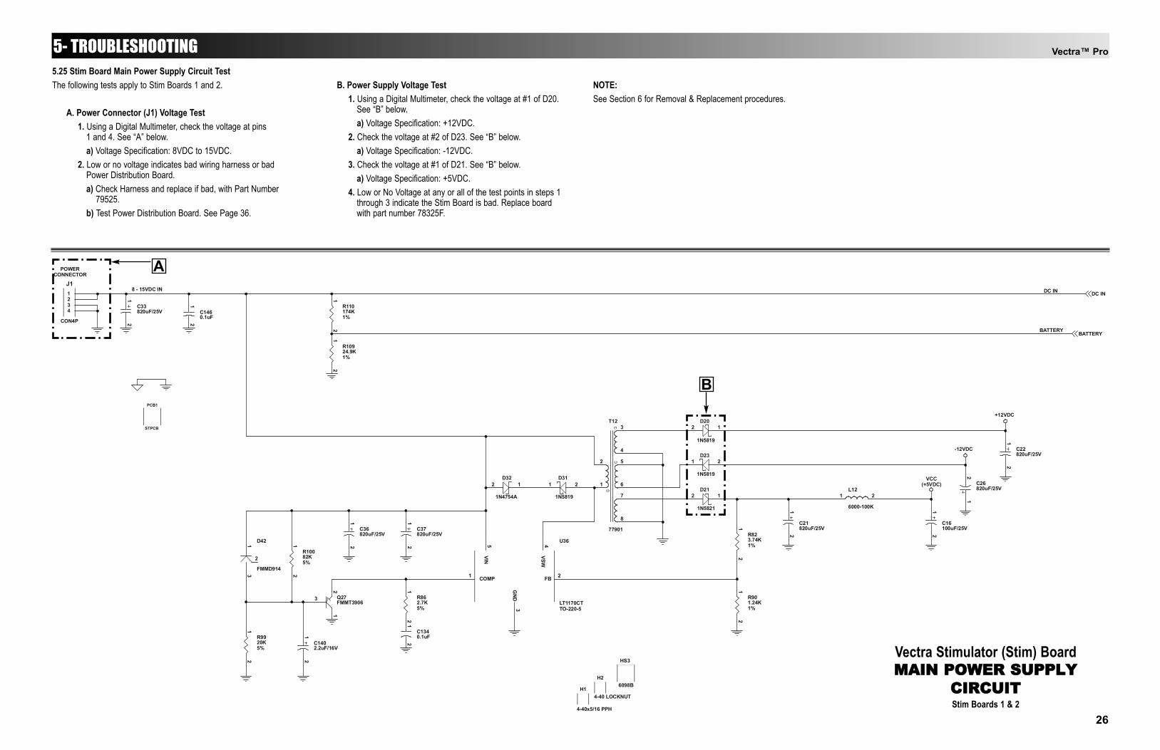
5.25 Stim Board Main Power Supply Circuit TestThe following tests apply to Stim Boards 1 and 2.
A. Power Connector (J1) Voltage Test1. Using a Digital Multimeter, check the voltage at pins
1 and 4. See “A” below.a) Voltage Specification: 8VDC to 15VDC.
2. Low or no voltage indicates bad wiring harness or bad Power Distribution Board.a) Check Harness and replace if bad, with Part Number
79525.b) Test Power Distribution Board. See Page 36.
B. Power Supply Voltage Test1. Using a Digital Multimeter, check the voltage at #1 of D20.
See “B” below.a) Voltage Specification: +12VDC.
2. Check the voltage at #2 of D23. See “B” below.a) Voltage Specification: -12VDC.
3. Check the voltage at #1 of D21. See “B” below.a) Voltage Specification: +5VDC.
4. Low or No Voltage at any or all of the test points in steps 1 through 3 indicate the Stim Board is bad. Replace board with part number 78325F.
NOTE:See Section 6 for Removal & Replacement procedures.
B
26

R5610.0K1%
12
R5910.0K1%
12
R6010.0K1%
12
U30A
LF453CMSO-8
3
21
84
+
-
C1310.1uF
12
C1300.1uF
12
R84
4.99K1%
1 2
U39
HCPL-2631DIP8
ANOD11
CATHOD12
CATHOD23
ANOD24
GND5
VCC8
VO17
VO26
U38
HCPL-2601DIP8
ANODE2
CATHOD3
GND5VOUT6VE7VCC8
C1380.1uF
12
C1390.1uF
12
U33
AD7233ANDIP8
VDD1
SCLK2
SDIN3
SYNC4
VSS8
VOUT7
GND6
LDAC5
Q19FMMT5401SOT-23
3
21
Q16FMMT5551SOT-23
3
21
R61100.000.1%
12
R65100.000.1%
12
R62100.000.1%
12
R58100.000.1%
12
R964705%
12
R954705%
12
R974705%
12
Q15FMMT5551
SOT-23
3
21
Q20FMMT5551
SOT-23
3
21
Q21FMMT5551
SOT-23
3
21
Q17FMMT5401
SOT-23
3
21
Q22FMMT5401
SOT-23
3
21
Q23FMMT5401
SOT-23
3
21
Q18FMMT5551
SOT-23
3
21
C1350.1uF
12
C1270.1uF
12
R64100.01%
12
R63100.01%
12
C124820pF
12
R69100.0K1%
12
+60V
ISOGND1
+12V1
-12V1
MICROI
/MCCLK
/MCDAT
/MCSYNC
-60V
ISOGND1
MICROI
+60V
-60V
+12V1
-12V1
/MCCLK
/MCDAT
/MCSYNC
+/- 60V COMPLIANT+/- 1mA MAX CURRENT
VOLTAGE-CONTROLLED CURRENT PUMP
12-BIT DAC
+/-5V
OPTO-ISOLATORS
VCC
R107
FMMD914D45
3
2
1
4705%
R1064705%
VCC
FMMD914D46
1
2
3
R108
5%470
VCC
1
D47FMMD914
2
3
Vectra™ Pro5- TROUBLESHOOTING
Vectra Stimulator (Stim) BoardMICROCURRENT
CIRCUITStim Boards 1 & 2
5.26 Stim Board Microcurrent Circuit TestThe following tests apply to Stim Boards 1 and 2.
A. Microcurrent Output Test1. Set Scope;
a) Time- 250ns, Channel- 2.0V, Trigger- DCb) Reference Scope to DC Ground.
2. Check pins 1 and 4 of U39 (see “A” below) for presence of square wave. See Figure 5.36.
3. Check pin 2 of U38 (see “B” below) for presence of square wave. See Figure 5.36.
4. Absence of square wave at any or all of the check points in steps 2 and 3 indicate bad stim board. Replace with Part Number 78325F.
NOTE:See Section 6 for Removal & Replacement procedures.
A
B
FIGURE 5.36
27
Vectra™ Pro
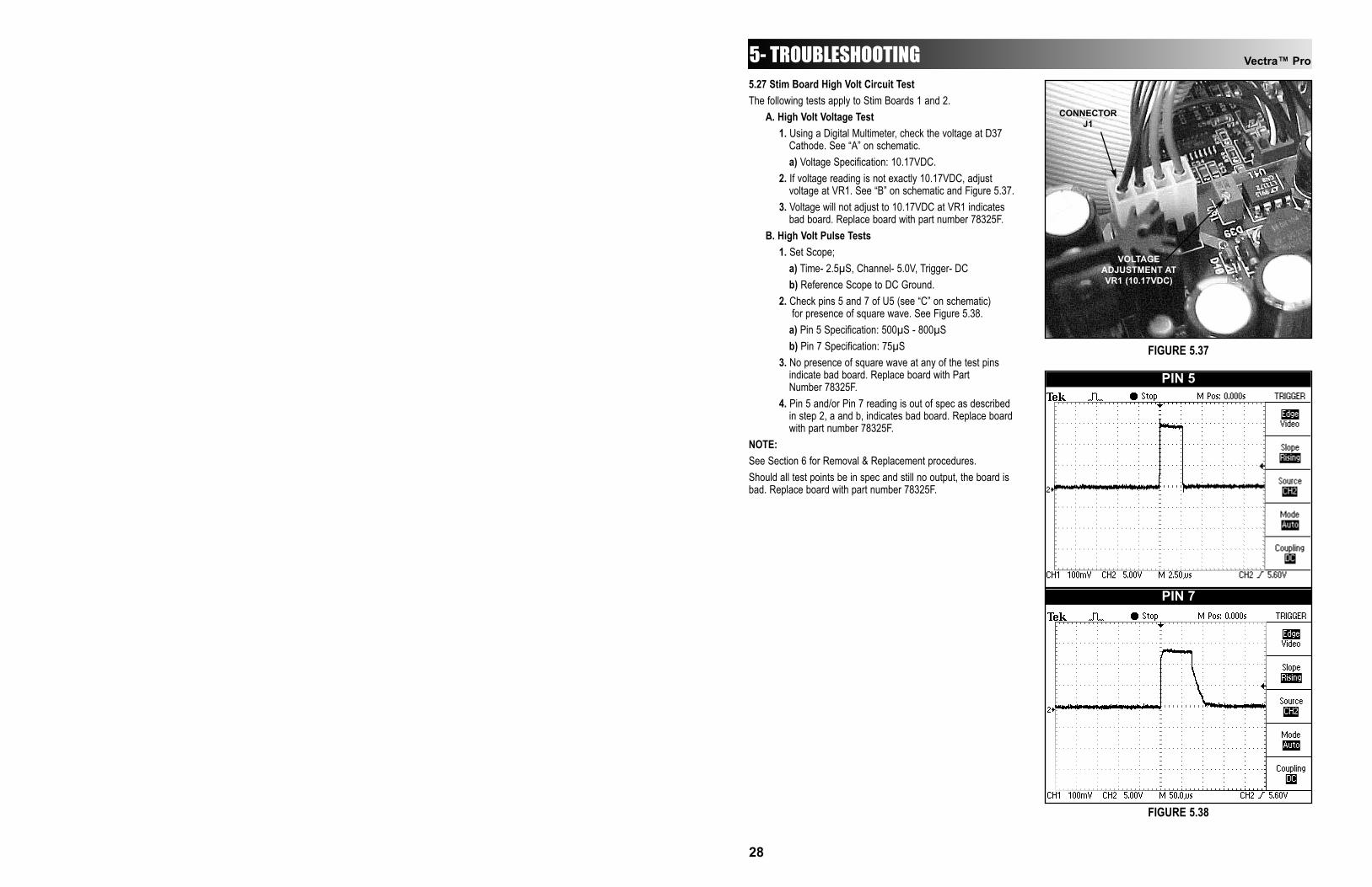
5.27 Stim Board High Volt Circuit TestThe following tests apply to Stim Boards 1 and 2.
A. High Volt Voltage Test1. Using a Digital Multimeter, check the voltage at D37
Cathode. See “A” on schematic.a) Voltage Specification: 10.17VDC.
2. If voltage reading is not exactly 10.17VDC, adjust voltage at VR1. See “B” on schematic and Figure 5.37.
3. Voltage will not adjust to 10.17VDC at VR1 indicates bad board. Replace board with part number 78325F.
B. High Volt Pulse Tests1. Set Scope;
a) Time- 2.5µS, Channel- 5.0V, Trigger- DCb) Reference Scope to DC Ground.
2. Check pins 5 and 7 of U5 (see “C” on schematic) for presence of square wave. See Figure 5.38.
a) Pin 5 Specification: 500µS - 800µSb) Pin 7 Specification: 75µS
3. No presence of square wave at any of the test pins indicate bad board. Replace board with Part Number 78325F.
4. Pin 5 and/or Pin 7 reading is out of spec as described in step 2, a and b, indicates bad board. Replace boardwith part number 78325F.
NOTE:See Section 6 for Removal & Replacement procedures.Should all test points be in spec and still no output, the board isbad. Replace board with part number 78325F.
5- TROUBLESHOOTING
VOLTAGEADJUSTMENT ATVR1 (10.17VDC)
CONNECTORJ1
FIGURE 5.37
FIGURE 5.38
28
PIN 5
PIN 7

Vectra™ Pro
C510.1uF
12
C500.1uF
12
D1
FR1M
2 1
D4
FR1M
2 1
U41
LT1172CN8DIP8
VSW7VIN
5
GN
D1
E16
FB3
NC4
VC2 E2
8
C720.01uF
12
C6118pF
12
U8A
LF453CMSO-8
3
21
84
+
-
U8B
LF453CMSO-8
5
67
+
-
C630.1uF
12
C750.1uF
12
R116
2.7K5%
1 2
Q4NLSOT-23
3
12
R19105%
12
T3
PE-5762
3
4
6
5
1
2
R10
1.00K1%
1 2
R14
1.00K1%
1 2
D37
1N5819
2 1
R111
NL
1 2T271331
4 3
21
D21N5819
21
Q2S601-E
213
Q3S601-E
2
13
C520.1uF
12
R1171.00K1%
12
R986.8K5%
12
C10.01uF/630V
12
C20.015uF/630V
12
D51N4762
21
U5
MC34152PDIP8
NC1
IN12
GND3
IN24
NC8
OUT17
VDD6
OUT25
C3100uF/25V
12
L1
100uH/1812
1 2
C1450.01uF
12
D391N5819
21
C322200uF/16V
12
C38220uF/25V
12
R210MEG 1/4 WATT5%
12
R12.49K 1/4 WATT1%
12
R9
64.91%
1 2
C51.0uF/50V
12
R310MEG 1/4 WATT5%
12
C410uF/50V
12
VR12.0K 10T
3 1
2
T4
77918
2
1
3
4
Q1IRF540TO-220
1
23
T1NL
1 2
3 4
T13
CTX50-4
1 4
2 3
K1
G5V-2-H-DC5
46
8
1311
91
16
C56
0.1uF
1 2
D401N4754A
21
R1364.91%
12
R18
10.0K1%
1 2
R17
1.0K1%
1 2
D7ZC5800E
3 1
2
D6ZC5800E
3 1
2
HV I
DC IN
HVPOS
HVNEG
/MCDAT
/MCCLK/MCSYNC
ADC CLK
VCCVCC
-12V
+12V
+12V
-12V
VCC
+12V
VCC
HV I
DC IN
HVNEG
HVPOS
/MCDAT
/MCCLK/MCSYNC
ADC CLK
POLARITY RELAY
1 : 50
PEAK DETECTOR
0 - 2.5V
HIVOLT CAL
ADJUSTABLE 11 VOLT SUPPLY
1 : 8
Lp = 50uH
HVRELAY
TO:Input/output
Section
Vectra Stimulator (Stim) BoardHIGH VOLT
CIRCUITStim Boards 1 & 2
A
B
C
5- TROUBLESHOOTING
29
Vectra™ Pro
C990.1uF
12
C980.1uF
12
Q8IRFD120DIP4
3
14
2
R25
105%
1 2R29
105%
1 2
R24
105%
1 2R20
105%
1 2R421.00K1%
12
R35100.0K1%
12
R38100.0K1%
12
C110
0.1uF/100V
1 2
C105
0.1uF/100V
1 2
C1060.1uF
12
C83
0.1uF
1 2
Q7IRFD120DIP4
3
14
2
Q11IRFD120DIP4
3
14
2
Q12IRFD120DIP4
3
14
2
T7
HY3479
1 10
5 6
C760.1uF/100V
12
C650.1uF/100V
12
L7
100uH/1812
1 2
C11
100uF/25V
1 2
C581000pF
12
C150.18uF/100V
12
C200.018uF/100V
12
C190.018uF/100V
12
C140.18uF/100V
12
K3
G5V-2-H-DC5
46
8
1311
91
16
C67
0.1uF
1 2C121
0.1uF
1 2
L5
6000-561K
1 2L11
6000-561K
1 2
L4
6000-561K
1 2L10
6000-561K
1 2
K4
G5V-2-H-DC5
46
8
1311
9116
C9
33uF/50V
1 2
C8
33uF/50V
1 2
T9PE-67100
1 2
3 4
D13
HER105
21
D15
HER105
21
U15
HIP4081AIPDIP20
BHB1
BHI2
DIS3
VSS4
BLI5
ALI6
AHI7
HDEL8
LDEL9
AHB10
BHO20
BHS19
BLO18
BLS17
VDD16
VCC15
ALS14
AL013
AHS12
AHO11
R50.5 1W1%
12
R66
100.01%
1 2
+60V1
SINECUR1
PWM1
ISOGND1PWMA3PWMA1
PULSECUR1
SENSESEL1
VCC VCC
+12V
VCCVCC
VCC VCC
ISOGND1
PWM1
+60V1
SENSESEL1
PULSECUR1
SINECUR1
POWER AMPCLASS-S
MOSFET DRIVER
26KHZ CHEBYSHEV DIFFERENTIAL LPF
OUTPUT TRANSFORMER1 : 2
TO: I
nput
/Out
put S
ectio
n
TO: Input/Output Section
Vectra Stimulator (Stim) BoardVMS, Interferential,
Premodulated, RussianCIRCUITS
Stim Board 1- Channel 1Stim Board 2- Channel 3
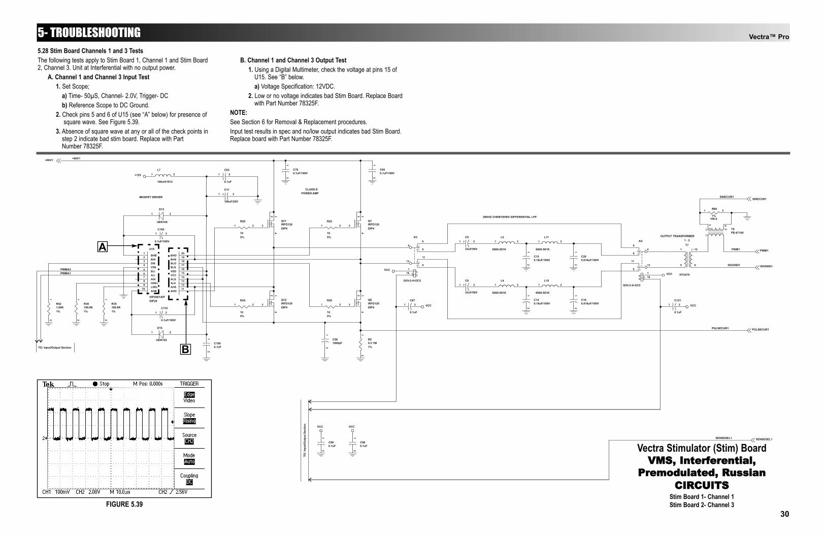
5.28 Stim Board Channels 1 and 3 TestsThe following tests apply to Stim Board 1, Channel 1 and Stim Board2, Channel 3. Unit at Interferential with no output power.
A. Channel 1 and Channel 3 Input Test1. Set Scope;
a) Time- 50µS, Channel- 2.0V, Trigger- DCb) Reference Scope to DC Ground.
2. Check pins 5 and 6 of U15 (see “A” below) for presence of square wave. See Figure 5.39.
3. Absence of square wave at any or all of the check points in step 2 indicate bad stim board. Replace with Part Number 78325F.
B. Channel 1 and Channel 3 Output Test1. Using a Digital Multimeter, check the voltage at pins 15 of
U15. See “B” below.a) Voltage Specification: 12VDC.
2. Low or no voltage indicates bad Stim Board. Replace Board with Part Number 78325F.
NOTE:See Section 6 for Removal & Replacement procedures.Input test results in spec and no/low output indicates bad Stim Board.Replace board with Part Number 78325F.
FIGURE 5.39
A
B
5- TROUBLESHOOTING
30
C700.1uF
12
C740.1uF
12
Q6IRFD120DIP4
3
14
2
R27
105%
1 2R30
105%
1 2
R26
105%
1 2R21
105%
1 2R431.00K1%
12
R36100.0K1%
12
R39100.0K1%
12
C111
0.1uF/100V
1 2
C107
0.1uF/100V
1 2
C1080.1uF
12
C84
0.1uF
1 2
Q5IRFD120DIP4
3
14
2
Q9IRFD120DIP4
3
14
2
Q10IRFD120DIP4
3
14
2
T6
HY3479
1 10
5 6
C770.1uF/100V
12
C660.1uF/100V
12
L6
100uH/1812
1 2
C10
100uF/25V
1 2
C591200pF
12
K5
G5V-2-H-DC5
46
8
1311
9116
C130.18uF/100V
12
C120.18uF/100V
12
C180.018uF/100V
12
C170.018uF/100V
12
K2
G5V-2-H-DC5
46
8
1311
91
16
C68
0.1uF
1 2C122
0.1uF
1 2
C6
33uF/50V
1 2
C7
33uF/50V
1 2L3
6000-561K
1 2L9
6000-561K
1 2
L2
6000-561K
1 2L8
6000-561K
1 2
T8PE-67100
1 2
3 4
D12
HER105
21
D14
HER105
21
U14
HIP4081AIPDIP20
BHB1
BHI2
DIS3
VSS4
BLI5
ALI6
AHI7
HDEL8
LDEL9
AHB10
BHO20
BHS19
BLO18
BLS17
VDD16
VCC15
ALS14
AL013
AHS12
AHO11
R40.5 1W1%
12
R67
100.01%
1 2
+60V2
SINECUR2
PWM2
ISOGND2PWMB3PWMB1
PULSECUR2
SENSESEL2
VCC VCC
+12V
VCCVCC
VCC VCC
ISOGND2
PWM2
+60V2
PULSECUR2
SINECUR2
SENSESEL2
POWER AMPCLASS-S
MOSFET DRIVER
26KHZ CHEBYSHEV DIFFERENTIAL LPFOUTPUT TRANSFORMER
1 : 2
TO: I
nput
/Out
put S
ectio
n
TO: Input/Output Section
Vectra™ Pro5- TROUBLESHOOTING
Vectra Stimulator (Stim) BoardVMS, Interferential,
Premodulated, RussianCIRCUITS
Stim Board 1- Channel 2Stim Board 2- Channel 4
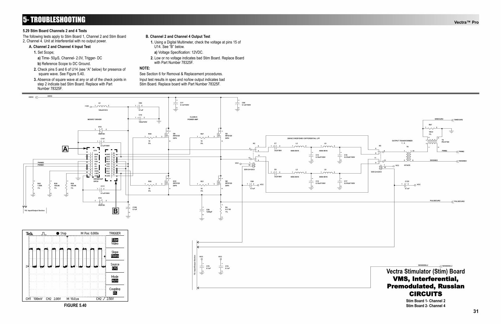
5.29 Stim Board Channels 2 and 4 TestsThe following tests apply to Stim Board 1, Channel 2 and Stim Board2, Channel 4. Unit at Interferential with no output power.
A. Channel 2 and Channel 4 Input Test1. Set Scope;
a) Time- 50µS, Channel- 2.0V, Trigger- DCb) Reference Scope to DC Ground.
2. Check pins 5 and 6 of U14 (see “A” below) for presence of square wave. See Figure 5.40.
3. Absence of square wave at any or all of the check points in step 2 indicate bad Stim Board. Replace with Part Number 78325F.
B. Channel 2 and Channel 4 Output Test1. Using a Digital Multimeter, check the voltage at pins 15 of
U14. See “B” below.a) Voltage Specification: 12VDC.
2. Low or no voltage indicates bad Stim Board. Replace Board with Part Number 78325F.
NOTE:See Section 6 for Removal & Replacement procedures.Input test results in spec and no/low output indicates bad Stim Board. Replace board with Part Number 78325F.
FIGURE 5.40
A
B
31
Vectra™ Pro
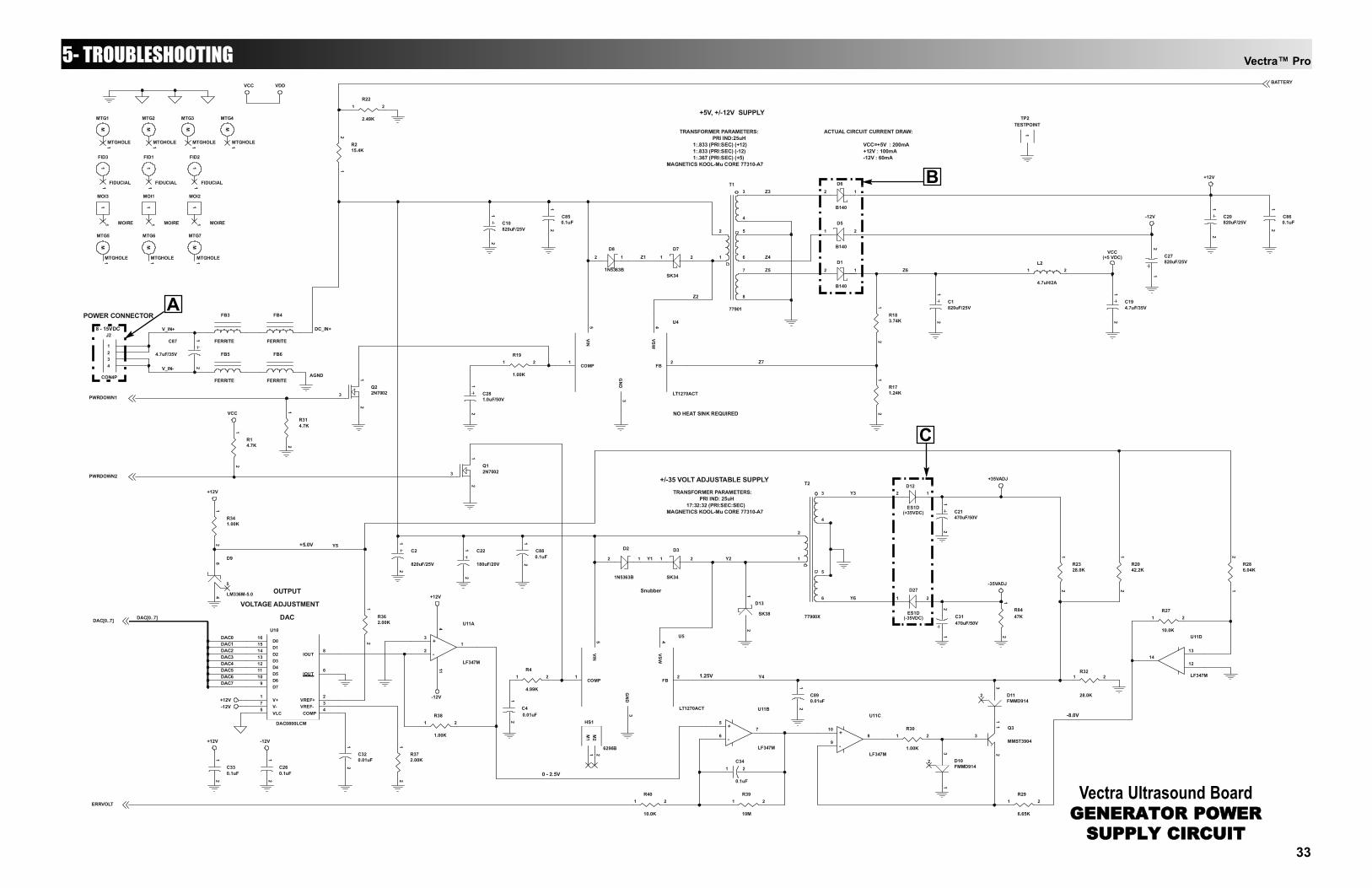
5.30 Ultrasound Board Generator Circuit TestA. Power Connector Voltage Test
1. Using a Digital Multimeter, check the voltage at pins 1 and 4. See “A” on schematic.a) Voltage Specification: 8VDC to 15VDC.
2. Low or no voltage indicates bad wiring harness or bad Power Distribution Board.a) Check Harness and replace if bad with Part Number
79524.b) Test Power Distribution Board. See Page 36.
B. Power Supply Voltage Test1. Using a Digital Multimeter, check the voltage at #1 of
D6. See “B” on schematic.a) Voltage Specification: +12VDC.
2. Check the voltage at #2 of D5. See “B” below.a) Voltage Specification: -12VDC.
3. Check the voltage at #1 of D1. See “B” below.a) Voltage Specification: +5VDC.
4. Low or No Voltage at any or all of the test points in steps 1 through 3 indicate the Ultrasound Board is bad. Replace board with Part Number 79291D.
C. Output Voltage Test1. Using a Digital Multimeter, check the voltage at #1 of
D12. See “C” schematic.a) Voltage Specification: +35VDC.
2. Check the voltage at #2 of D27. See “C” below.a) Voltage Specification: -35VDC.
3. Low or No Voltage at any or all of the test points in steps 1 and/or 2 indicate the Ultrasound Board is bad. Replace board with Part Number 79291D.
NOTE:See Section 6 for Removal & Replacement procedures.
5- TROUBLESHOOTING
32
Vectra™ Pro5- TROUBLESHOOTING
R183.74K
12
R171.24K
12
C2
820uF/25V
12
C320.01uF
12C33
0.1uF
12
C260.1uF
12
R362.00K
12
R372.00K
12
R38
1.00K
1 2
C34
0.1uF
1 2
R215.4K
12
R22
2.49K
1 2
C1820uF/25V
12
C194.7uF/35V
12
C27820uF/25V
12
C20820uF/25V
12
R341.00K
12
U10
DAC0800LCM
D016
D115
D214
D313
D412
D511
D610
D79
V+1
V-7
VLC5
COMP4
VREF+2
VREF-3
IOUT8
IOUT6
U4
LT1270ACT
VIN5
COMP1
FB2
GND
3
VSW4
Q22N70023
12
Q12N70023
12
C22
180uF/20V
12
R314.7K
12
R14.7K
12
C40.01uF
12
R4
4.99K
1 2
R40
10.0K
1 2R39
10M
1 2
R27
10.0K
1 2
R2328.0K
12
C21470uF/50V
12
U11A
LF347M
3
21
411
+
-
U11B
LF347M
5
67+
-
R32
28.0K
1 2
R30
1.00K
1 2
R286.04K
12
R29
6.65K
1 2
R2042.2K
12
U11D
LF347M
12
1314
J2
CON4P
1234
D11FMMD914
31
2
D10FMMD914
31
2
Q3
MMST39043
21
T1
77901
3
4
5
6
7
8
2
1
D8
1N5363B
2
D2
1N5363B
2 1
C281.0uF/50V
12
R19
1.00K
1 2
L2
4.7uH/2A
1 2
MTG7
MTGHOLE
M1
MTG5
MTGHOLE
M1
MOI1
MOIRE
11
MOI2
MOIRE
11
MOI3
MOIRE
11
FID3
FIDUCIAL
11
FID1
FIDUCIAL
11
FID2
FIDUCIAL
11
HS1
6296B
M1
1M
22
MTG1
MTGHOLE
M1
MTG4
MTGHOLE
M1
MTG2
MTGHOLE
M1
MTG3
MTGHOLE
M1
D9
LM336M-5.048
5
C31470uF/50V
12
D27
ES1D(-35VDC)
21
D12
ES1D(+35VDC)
2 1
T2
77900X
3
4
6
5
1
2
D3
SK34
21
D7
SK34
21
D6
B140
2 1
D5
B140
21
D1
B140
2 1
D13
SK382
1
TP2TESTPOINT
1
MTG6
MTGHOLE
M1
C880.1uF
12
C850.1uF
12
C10820uF/25V
12
U11C
LF347M
10
98+
-
U5
LT1270ACT
VIN5
COMP1
FB2
GND
3
VSW4
C890.01uF
12
C860.1uF
12
FB3
FERRITEC87
4.7uF/35V
12
FB4
FERRITE
FB6
FERRITE
FB5
FERRITE
R8447K
12
Z1 Z4
Z5
Z2
Z7
DAC0DAC1DAC2DAC3DAC4DAC5DAC6DAC7
DAC[0..7]
Z6
Y1
Z3
Y3
Y5
Y6
Y2
Y4
V_IN-
V_IN+
AGND
DC_IN+
+35VADJ
VCC(+5 VDC)
-12V
+12V
+12V -12V
+12V
VCC
-12V+12V-12V
VDDVCC
-35VADJ
+12V
DAC[0..7]
ERRVOLT
PWRDOWN1
PWRDOWN2
BATTERY
1.25V
TRANSFORMER PARAMETERS:PRI IND: 25uH
MAGNETICS KOOL-Mu CORE 77310-A7
VOLTAGE ADJUSTMENT
DAC
OUTPUT
0 - 2.5V
8 - 15VDC
POWER CONNECTOR
+5.0V
-8.0V
17:32:32 (PRI:SEC:SEC)
NO HEAT SINK REQUIRED
+/-35 VOLT ADJUSTABLE SUPPLY
1:.833 (PRI:SEC) (-12)1:.833 (PRI:SEC) (+12)
PRI IND:25uH
MAGNETICS KOOL-Mu CORE 77310-A7
TRANSFORMER PARAMETERS:
1:.367 (PRI:SEC) (+5)
+5V, +/-12V SUPPLY
VCC=+5V : 200mA+12V : 100mA-12V : 60mA
ACTUAL CIRCUIT CURRENT DRAW:
Snubber
1
Vectra Ultrasound BoardGENERATOR POWER
SUPPLY CIRCUIT
A
B
C
33
Vectra™ Pro
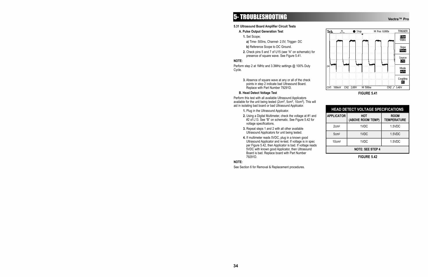
5.31 Ultrasound Board Amplifier Circuit TestsA. Pulse Output Generation Test
1. Set Scope;a) Time- 500ns, Channel- 2.0V, Trigger- DCb) Reference Scope to DC Ground.
2. Check pins 5 and 7 of U15 (see “A” on schematic) for presence of square wave. See Figure 5.41.
NOTE:Perform step 2 at 1MHz and 3.3MHz settings @ 100% DutyCycle.
3. Absence of square wave at any or all of the check points in step 2 indicate bad Ultrasound Board. Replace with Part Number 79291D.
B. Head Detect Voltage TestPerform this test with all available Ultrasound Applicatorsavailable for the unit being tested (2cm2, 5cm2, 10cm2). This willaid in isolating bad board or bad Ultrasound Applicator.
1. Plug in the Ultrasound Applicator.2. Using a Digital Multimeter, check the voltage at #1 and
#2 of L13. See “B” on schematic. See Figure 5.42 for voltage specifications.
3. Repeat steps 1 and 2 with all other available Ultrasound Applicators for unit being tested.
4. If multimeter reads 5VDC, plug in a known good Ultrasound Applicator and re-test. If voltage is in spec per Figure 5.42, then Applicator is bad. If voltage reads5VDC with known good Applicator, then Ultrasound Board is bad. Replace board with Part Number 79291D.
NOTE:See Section 6 for Removal & Replacement procedures.
5- TROUBLESHOOTING
HEAD DETECT VOLTAGE SPECIFICATIONS APPLICATOR HOT
(ABOVE ROOM TEMP) ROOM
TEMPERATURE
2cm2 1VDC 1.5VDC
5cm2 1VDC 1.5VDC
10cm2 1VDC 1.5VDC
NOTE: SEE STEP 4
FIGURE 5.41
FIGURE 5.42
34
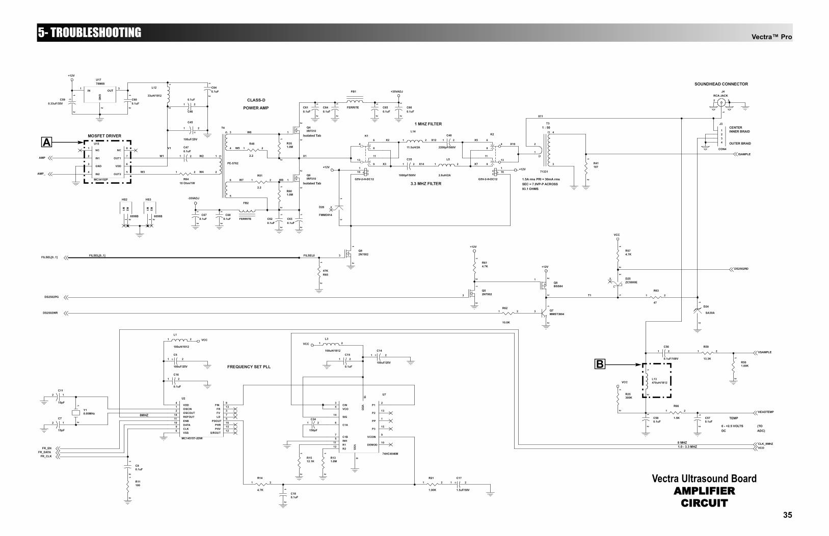
Vectra™ Pro5- TROUBLESHOOTING
C580.1uF
12
Y18.00MHz
12
C11
15pF
12
C7
15pF
12
C180.1uF
12
C24
150pF
1 2
R1512.1K
12
R131.0M
12
R11100
12
C16
0.1uF
1 2
C5
100uF/25V
1 2
C14
100uF/25V
1 2
R574.7K
12
Q52N70023
12
Q8BSS84
13
2
R614.7K
12
R21
1.00K
1 2R14
4.7K
1 2
J3
CON4
1234
U7
74HC4046M
CIN3
VCO4
SIG14
C1A6
C1B7
INH5
R111
R212
P12
VCOIN9
DEMOD10VSS
8
VDD
16
P213
PP1
P315
U2
MC145157-2DW
FIN8
FR13
FV3
LD7
PDOUT5
PHR16
PHV15
S/ROUT12
VDD4
VSS6 CLK9 DATA
10 ENB11 REFOUT14 OSCOUT
2 OSCIN1
C17
1.5uF/50V
1 2
Q6IRF5101
23
C470.1uF
1 2
R351.0M
12
C56
0.1uF/100V
1 2R59
13.3K
1 2
R501.00K
12
U15
MC34152P
NC1
IN12
GND3
IN24
NC8
OUT17
VDD6
OUT25
R41187
12
R601.0M
12
C80.1uF
12
D25ZC5800E
31
2
R51
2.2
1 2
L1
100uH/1812
1 2 L3
100uH/1812
1 2
L13470uH/1812
12
T4
PE-5762
3
4
6
5
1
2
R25300K
12
HS2
6098B
M1
1M
22
HS3
6098B
M1
1M
22
R62
10.0K
1 2 Q7MMST3904
3
21
Q92N70023
12
Q4IRF5101
23
K2
G5V-2-H-DC12
46
8
1311
9116
L5
2.8uH/2A
1 2
D26
FMMD914
31
2
K1
G5V-2-H-DC12
46
8
1311
91
16
R6547K
12
R63
47
1 2
C35
1000pF/500V
1 2
C15
0.1uF
1 2
C46
0.1uF1 2
C600.1uF
12
C45
100uF/25V
1 2
C590.33uF/35V
12
C620.1uF
12
C610.1uF
12
R6410 Ohm/1W
1 2
D24
SA30A
21
L14
11.5uH/2A
1 2C48
2200pF/500V
1 2
T3
71331
4
3
2
1
J4RCA JACK
31
2
R66
1.5K
1 2
C570.1uF
12
C640.1uF
12
C650.1uF
12
C660.1uF
12
FB1
FERRITE
C630.1uF
12
R48
2.2
1 2
C680.1uF
12
C670.1uF
12
FB2
FERRITE
U1778M08
IN1
GND
2
OUT3 L12
33uH/1812
12
C840.1uF
12
W1
W7 W8
FILSEL[0..1]
T1
W2
W4
X10
X1
W3
X14X3
FILSEL0
X11
X12X2 X5
X7
W6
W5V1
VCC
VCC
+12V
+12V
VCCVCC
+12V+12V
+12V
+35VADJ
-35VADJ
HEADTEMP
VSAMPLE
FR_ENFR_DATA
FR_CLK
DS2502WR
DS2502RD
DS2502PG
AMP
CLK_8MHZVCO
FILSEL[0..1]
ISAMPLE
AMP_
TEMP
CENTER
OUTER BRAID
INNER BRAID
SOUNDHEAD CONNECTOR
(TOADC)
0 - +2.5 VOLTSDC
MOSFET DRIVER
POWER AMP
1.0 - 3.3 MHZ
FREQUENCY SET PLL
8MHZ
8 MHZ
CLASS-D
1 MHZ FILTER
3.3 MHZ FILTER1.5A rms PRI = 30mA rmsSEC = 7.9VP-P ACROSS93.1 OHMS
1 : 50
Isolated Tab
Isolated Tab
Vectra Ultrasound BoardAMPLIFIER
CIRCUIT
A
B
35
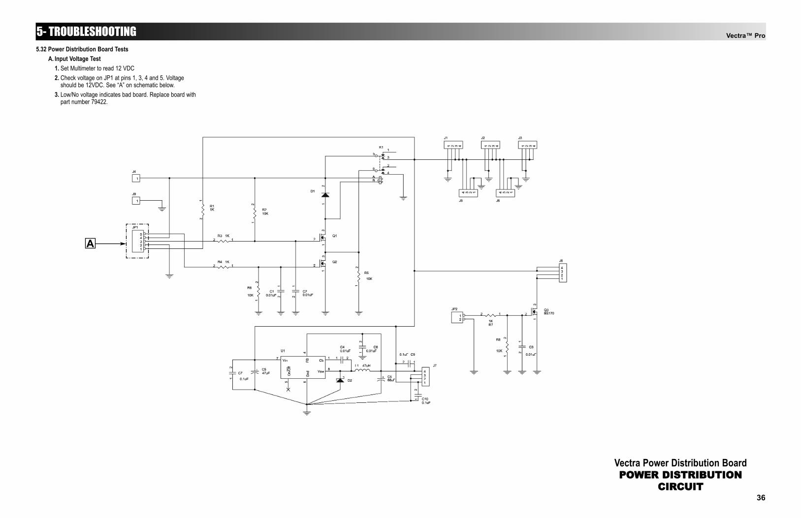
Vectra™ Pro5- TROUBLESHOOTING
Vectra Power Distribution BoardPOWER DISTRIBUTION
CIRCUIT
5.32 Power Distribution Board TestsA. Input Voltage Test
1. Set Multimeter to read 12 VDC2. Check voltage on JP1 at pins 1, 3, 4 and 5. Voltage
should be 12VDC. See “A” on schematic below.3. Low/No voltage indicates bad board. Replace board with
part number 79422.
36
A


Vectra™ Pro
37
6- REMOVAL & REPLACEMENT6.1 General
A. Tools & Equipment Required1. #2 Phillips Screwdriver2. #1 Phillips Screwdriver3. Small adjustable wrench
6.2. Fuse ReplacementA. Unplug the unit from the power source and remove
power cord from the unit.B. Slide Fuse Housing open from the Mains Connector on
the unit. See Figure 6.1.C. Pull fuses from housing and replace with new fuses, Part
Number 72103 (two required). See Figure 6.2.D. Slide Fuse Housing back into place. Make certain it is
completely closed, otherwise the fuses may not make fullcontact.
6.3 Top & Bottom of UnitA. Removing Top from Bottom
1. Place unit face down on a grounded work surface.2. Remove the 10 mounting screws holding the top and
bottom together. See Figure 6.3.3. Carefully separate the bottom from the top.
B. Installing Top to Bottom1. With top laying face down, carefully place the bottom
in position over the top.2. Secure with the phillips head screws.
NOTE:Do not overtighten the screws. Overtightening will damage thethreads of the brass inserts.
WARNING!UNPLUG THE UNIT FROM THE POWER SOURCEBEFORE ATTEMPTING ANY REMOVAL ORREPLACEMENT PROCEDURES TO PREVENTELECTRICAL SHOCK.
FIGURE 6.1
FIGURE 6.2
OPEN FUSEHOUSING
MAINSCONNECTOR
REMOVE & REPLACEFUSES
FIGURE 6.3
REMOVE 10MOUNTING SCREWS
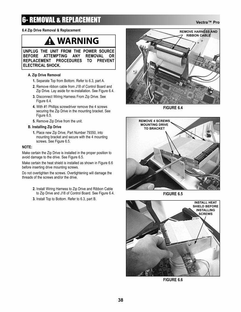
Vectra™ Pro
38
6.4 Zip Drive Removal & Replacement
A. Zip Drive Removal1. Separate Top from Bottom. Refer to 6.3, part A.2. Remove ribbon cable from J18 of Control Board and
Zip Drive. Lay aside for re-installation. See Figure 6.4.3. Disconnect Wiring Harness From Zip Drive. See
Figure 6.4.4. With #1 Phillips screwdriver remove the 4 screws
securing the Zip Drive in the mounting bracket. See Figure 6.5.
5. Remove Zip Drive from the unit.B. Installing Zip Drive
1. Place new Zip Drive, Part Number 79350, into mounting bracket and secure with the 4 mounting screws. See Figure 6.5.
NOTE:Make certain the Zip Drive is installed in the proper position toavoid damage to the drive. See Figure 6.5.Make certain the heat shield is installed as shown in Figure 6.6before inserting drive mounting screws.Do not overtighten the screws. Overtightening will damage thethreads of the screws and/or the drive.
2. Install Wiring Harness to Zip Drive and Ribbon Cable to Zip Drive and J18 of Control Board. See Figure 6.4.
3. Install Top to Bottom. Refer to 6.3, part B.
WARNING!UNPLUG THE UNIT FROM THE POWER SOURCEBEFORE ATTEMPTING ANY REMOVAL ORREPLACEMENT PROCEDURES TO PREVENTELECTRICAL SHOCK.
6- REMOVAL & REPLACEMENT
FIGURE 6.4
FIGURE 6.5
REMOVE HARNESS ANDRIBBON CABLE
REMOVE 4 SCREWSMOUNTING DRIVE
TO BRACKET
FIGURE 6.6
INSTALL HEATSHIELD BEFORE
INSTALLINGSCREWS
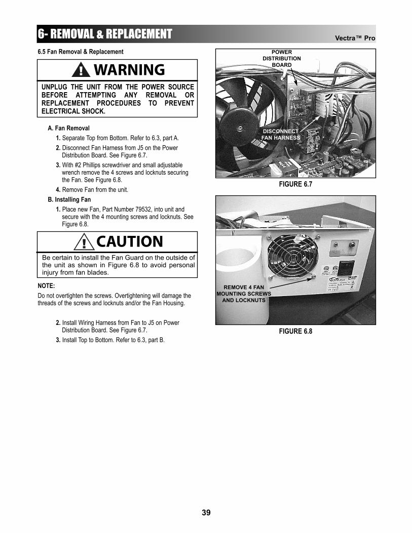
Vectra™ Pro
39
6.5 Fan Removal & Replacement
A. Fan Removal1. Separate Top from Bottom. Refer to 6.3, part A.2. Disconnect Fan Harness from J5 on the Power
Distribution Board. See Figure 6.7.3. With #2 Phillips screwdriver and small adjustable
wrench remove the 4 screws and locknuts securing the Fan. See Figure 6.8.
4. Remove Fan from the unit.B. Installing Fan
1. Place new Fan, Part Number 79532, into unit and secure with the 4 mounting screws and locknuts. See Figure 6.8.
NOTE:Do not overtighten the screws. Overtightening will damage thethreads of the screws and locknuts and/or the Fan Housing.
2. Install Wiring Harness from Fan to J5 on Power Distribution Board. See Figure 6.7.
3. Install Top to Bottom. Refer to 6.3, part B.
WARNING!UNPLUG THE UNIT FROM THE POWER SOURCEBEFORE ATTEMPTING ANY REMOVAL ORREPLACEMENT PROCEDURES TO PREVENTELECTRICAL SHOCK.
6- REMOVAL & REPLACEMENT
FIGURE 6.7
FIGURE 6.8
DISCONNECTFAN HARNESS
POWERDISTRIBUTION
BOARD
REMOVE 4 FANMOUNTING SCREWS
AND LOCKNUTS
! CAUTIONBe certain to install the Fan Guard on the outside ofthe unit as shown in Figure 6.8 to avoid personalinjury from fan blades.
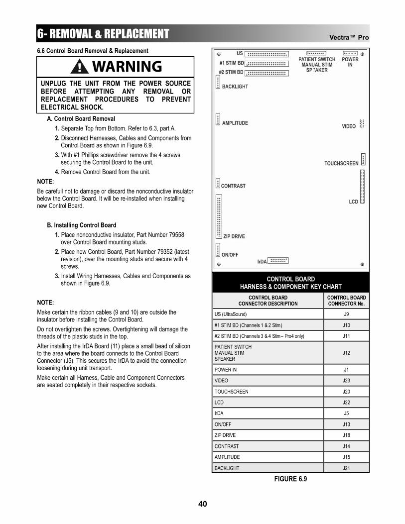
Vectra™ Pro
40
6.6 Control Board Removal & Replacement
A. Control Board Removal1. Separate Top from Bottom. Refer to 6.3, part A.2. Disconnect Harnesses, Cables and Components from
Control Board as shown in Figure 6.9.3. With #1 Phillips screwdriver remove the 4 screws
securing the Control Board to the unit.4. Remove Control Board from the unit.
NOTE:Be carefull not to damage or discard the nonconductive insulatorbelow the Control Board. It will be re-installed when installingnew Control Board.
B. Installing Control Board1. Place nonconductive insulator, Part Number 79558
over Control Board mounting studs.2. Place new Control Board, Part Number 79352 (latest
revision), over the mounting studs and secure with 4 screws.
3. Install Wiring Harnesses, Cables and Components as shown in Figure 6.9.
NOTE:Make certain the ribbon cables (9 and 10) are outside theinsulator before installing the Control Board.Do not overtighten the screws. Overtightening will damage thethreads of the plastic studs in the top.After installing the IrDA Board (11) place a small bead of siliconto the area where the board connects to the Control BoardConnector (J5). This secures the IrDA to avoid the connectionloosening during unit transport.Make certain all Harness, Cable and Component Connectorsare seated completely in their respective sockets.
6- REMOVAL & REPLACEMENT
CONTROL BOARD CONNECTOR DESCRIPTION
CONTROL BOARD CONNECTOR No.
US (UltraSound) J9
#1 STIM BD (Channels 1 & 2 Stim) J10
#2 STIM BD (Channels 3 & 4 Stim– Pro4 only) J11
PATIENT SWITCH MANUAL STIM SPEAKER
J12
POWER IN J1
VIDEO J23
TOUCHSCREEN J20
LCD J22
IrDA J5
ON/OFF J13
ZIP DRIVE J18
CONTRAST J14
AMPLITUDE J15
CONTROL BOARD HARNESS & COMPONENT KEY CHART
BACKLIGHT J21
FIGURE 6.9
WARNING!UNPLUG THE UNIT FROM THE POWER SOURCEBEFORE ATTEMPTING ANY REMOVAL ORREPLACEMENT PROCEDURES TO PREVENTELECTRICAL SHOCK.
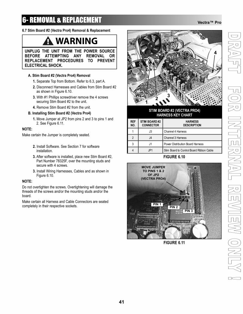
DDRRAAFFTT - FFOORR IINNTTEERRNNAALL RREEVVIIEEWW OONNLLYY !!Vectra™ Pro
41
6.7 Stim Board #2 (Vectra Pro4) Removal & Replacement
A. Stim Board #2 (Vectra Pro4) Removal1. Separate Top from Bottom. Refer to 6.3, part A.2. Disconnect Harnesses and Cables from Stim Board #2
as shown in Figure 6.10.3. With #1 Phillips screwdriver remove the 4 screws
securing Stim Board #2 to the unit.4. Remove Stim Board #2 from the unit.
B. Installing Stim Board #2 (Vectra Pro4)1. Move Jumper at JP2 from pins 2 and 3 to pins 1 and
2. See Figure 6.11.NOTE:Make certain the Jumper is completely seated.
2. Install Software. See Section 7 for software installation.
3. After software is installed, place new Stim Board #2, Part Number 78325F, over the mounting studs and secure with 4 screws.
3. Install Wiring Harnesses, Cables and as shown in Figure 6.10.
NOTE:Do not overtighten the screws. Overtightening will damage thethreads of the screws and/or the mounting studs and/or theboard.Make certain all Harness and Cable Connectors are seatedcompletely in their respective sockets.
6- REMOVAL & REPLACEMENT
13
4
2
REF NO.
STIM BOARD #2 CONNECTOR
HARNESS DESCRIPTION
1 J3 Channel 4 Harness
2 J4 Channel 3 Harness
3 J1 Power Distribution Board Harness
4 JP1 Stim Board to Control Board Ribbon Cable
STIM BOARD #2 (VECTRA PRO4) HARNESS KEY CHART
FIGURE 6.10
FIGURE 6.11
PIN 1PIN 2
PIN 3
MOVE JUMPERTO PINS 1 & 2
OF JP2(VECTRA PRO4)
WARNING!UNPLUG THE UNIT FROM THE POWER SOURCEBEFORE ATTEMPTING ANY REMOVAL ORREPLACEMENT PROCEDURES TO PREVENTELECTRICAL SHOCK.
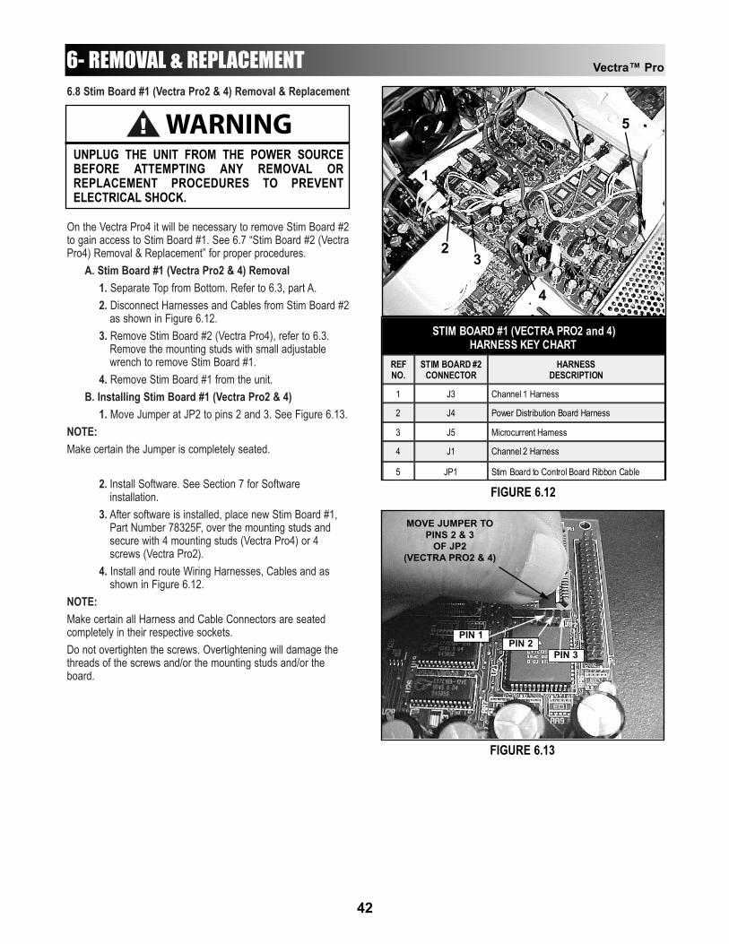
6.8 Stim Board #1 (Vectra Pro2 & 4) Removal & Replacement
On the Vectra Pro4 it will be necessary to remove Stim Board #2to gain access to Stim Board #1. See 6.7 “Stim Board #2 (VectraPro4) Removal & Replacement” for proper procedures.
A. Stim Board #1 (Vectra Pro2 & 4) Removal1. Separate Top from Bottom. Refer to 6.3, part A.2. Disconnect Harnesses and Cables from Stim Board #2
as shown in Figure 6.12.3. Remove Stim Board #2 (Vectra Pro4), refer to 6.3.
Remove the mounting studs with small adjustable wrench to remove Stim Board #1.
4. Remove Stim Board #1 from the unit.B. Installing Stim Board #1 (Vectra Pro2 & 4)
1. Move Jumper at JP2 to pins 2 and 3. See Figure 6.13.NOTE:Make certain the Jumper is completely seated.
2. Install Software. See Section 7 for Software installation.
3. After software is installed, place new Stim Board #1, Part Number 78325F, over the mounting studs and secure with 4 mounting studs (Vectra Pro4) or 4 screws (Vectra Pro2).
4. Install and route Wiring Harnesses, Cables and as shown in Figure 6.12.
NOTE:Make certain all Harness and Cable Connectors are seatedcompletely in their respective sockets.Do not overtighten the screws. Overtightening will damage thethreads of the screws and/or the mounting studs and/or theboard.
Vectra™ Pro
42
6- REMOVAL & REPLACEMENT
1
3
4
2
REF NO.
STIM BOARD #2 CONNECTOR
HARNESS DESCRIPTION
1 J3 Channel 1 Harness
2 J4 Power Distribution Board Harness
3 J5 Microcurrent Harness
4 J1 Channel 2 Harness
STIM BOARD #1 (VECTRA PRO2 and 4) HARNESS KEY CHART
5 JP1 Stim Board to Control Board Ribbon Cable
FIGURE 6.12
FIGURE 6.13
PIN 1PIN 2
PIN 3
MOVE JUMPER TOPINS 2 & 3
OF JP2(VECTRA PRO2 & 4)
5WARNING!UNPLUG THE UNIT FROM THE POWER SOURCEBEFORE ATTEMPTING ANY REMOVAL ORREPLACEMENT PROCEDURES TO PREVENTELECTRICAL SHOCK.
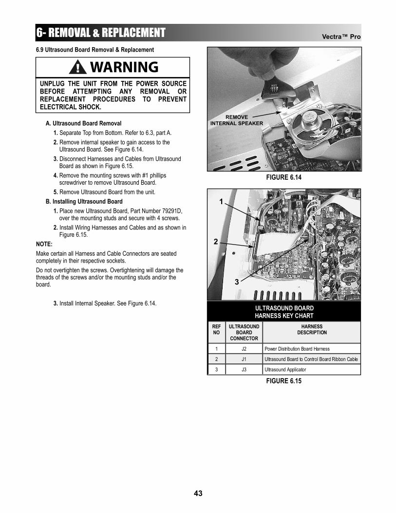
Vectra™ Pro
43
6.9 Ultrasound Board Removal & Replacement
A. Ultrasound Board Removal1. Separate Top from Bottom. Refer to 6.3, part A.2. Remove internal speaker to gain access to the
Ultrasound Board. See Figure 6.14.3. Disconnect Harnesses and Cables from Ultrasound
Board as shown in Figure 6.15.4. Remove the mounting screws with #1 phillips
screwdriver to remove Ultrasound Board.5. Remove Ultrasound Board from the unit.
B. Installing Ultrasound Board1. Place new Ultrasound Board, Part Number 79291D,
over the mounting studs and secure with 4 screws.2. Install Wiring Harnesses and Cables and as shown in
Figure 6.15.NOTE:Make certain all Harness and Cable Connectors are seatedcompletely in their respective sockets.Do not overtighten the screws. Overtightening will damage thethreads of the screws and/or the mounting studs and/or theboard.
3. Install Internal Speaker. See Figure 6.14.
6- REMOVAL & REPLACEMENT
FIGURE 6.14
FIGURE 6.15
REF NO
ULTRASOUND BOARD
CONNECTOR
HARNESS DESCRIPTION
1 J2 Power Distribution Board Harness
2 J1 Ultrasound Board to Control Board Ribbon Cable
3 J3 Ultrasound Applicator
ULTRASOUND BOARD HARNESS KEY CHART
1
3
2
REMOVEINTERNAL SPEAKER
WARNING!UNPLUG THE UNIT FROM THE POWER SOURCEBEFORE ATTEMPTING ANY REMOVAL ORREPLACEMENT PROCEDURES TO PREVENTELECTRICAL SHOCK.

Vectra™ Pro
44
7.1 Vectra Pro2 and Pro4 System Software and UpgradesA. Tools & Equipment Required
1. Internet access to the World Wide Web to download software from the Chattanooga Group, Inc Website (www.vectrapro.com).
2. Zip Drive (Internal or External) to accept downloaded software for Vectra Pro units.
NOTE:A “User Name” and “Password” must be obtained fromChattanooga Group, Inc. Service Department before Softwarecan be downloaded from the website. Software on Zip Disk may be ordered by ordering Part Number79604 and ask for the latest version of the System Software forthe Vectra Pro.The “Vectra Pro Software Version 1.XX Upgrade DownloadInstructions” may be printed.
3. When downloading make certain to carefully follow the“Vectra Pro Software Version 1.XX Upgrade DownloadInstructions” once access is gained.
B. System Software Installation1. With Unit “ON”, remove the Zip disk from the Vectra
Pro Zip Drive. See Figure 7.1.2. Press the Utilities icon in the top portion of the screen.
See Figure 7.2.3. Press “Clinic Name” icon.4. Enter “9876” using the keypad on the screen and
press “Enter”.5. Install system software Zip Disk into Zip Drive.6. Press “Install S/W” Icon. See Figure 7.3.7. After software has completed its install, remove the
system software Zip Disk from the Vectra Pro Zip Drive.
8. Re-install the “Multimedia/Anatomical Library Zip Disk into the Zip Drive and re-start the unit.
NOTE:“Strike a key when ready” indicates software installation iscomplete.The Software version number will appear in the upper portion ofthe splash screen.
7- SOFTWARE INSTALLATION
FIGURE 7.1
FIGURE 7.2
FIGURE 7.3

Vectra™ Pro
45
7.2 Stim Board SoftwareThe following instructions assume that the Stim Board(s) arealready removed from the unit. If not, refer to 6.7 and/or 6.8 forthe respective Stim Board.
A. Tools Required1. PLCC Extractor for installing stimulator board
software.The following instructions assume that the Stim Board(s) are already removed from the unit. If not, refer to 6.7 and/or 6.8 for the respective Stim Board.
B. Installation1. Using PLCC Extractor remove chips from U6 and U9.
See Figure 7.4.2. Using PLCC Extractor install new Software Chips into
their respective sockets. See Figure 7.5.3. Re-install board per 6.7 and/or 6.8 for the respective
board(s).NOTE:The decal on the Chip(s) indicate the respective socket forinstallation. See Figure 7.5.The Chips will only install one way into the socket. See Figure7.5.
7- SOFTWARE INSTALLATION
EXTRACTCHIPS
45° CHAMFERUPPER L.H.
CORNER
PART NO.
SOCKET NO.
VERSION NO.
FIGURE 7.4
FIGURE 7.5
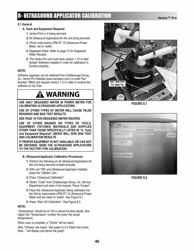
Vectra™ Pro
46
8.1 GeneralA. Tools and Equipment Required
1. Vectra Pro2 or 4 being serviced.2. All Ultrasound Applicators for the unit being serviced.3. Ohmic Instruments UPM DT 10 Ultrasound Power
Meter, set to “watts”.4. Degassed Water. Refer to page 10 for Degassed
Water Recipes.5. The Vectra Pro unit must have version 1.12 or later
System Software installed in order for calibration to function properly.
NOTE:Software upgrades can be obtained from Chattanooga Group,Inc. Vectra Pro Website (www.vectrapro.com) or order PartNumber 79604 and request version 1.12 or later to receive thesoftware on Zip Disk.
B. Ultrasound Applicator Calibration Procedures1. Perform the following on all Ultrasound Applicators for
the unit being serviced at least annually.2. With unit “ON” and Ultrasound Applicator installed,
press the “Utilities” icon.3. Press “Utrasound Calibration”.4. Obtain “Code” from Chattanooga Group, Inc. Service
Department and enter it into keypad. Press “Accept”.5. Place the Ultrasound Applicator being calibrated into
the Ohmic Instruments UPM DT 10 Ultrasound Power Meter and set meter to “watts”. See Figure 8.1.
6. Press “Start US Calibration”. See Figure 8.2.NOTE:“Temperature” should be at 125 or above for best results, (thehigher the “Temperature” number the lower the actualtemperature).When scan is complete, a “Chime” will be heard.After “Chimes” are heard, “Set power to 4.0 Watts then pressNext...” will display just above the graph.
8- ULTRASOUND APPLICATOR CALIBRATION
WARNING!USE ONLY DEGASSED WATER IN POWER METER FORCALIBRATING ULTRASOUND APPLICATORS.USE OF OTHER TYPES OF WATER WILL CAUSE FALSEREADINGS AND BAD TEST RESULTS.SEE PAGE 10 FOR DEGASSED WATER RECIPES.USE OF OTHER BRANDS OR TYPES OF TOOLS,EQUIPMENT, FIXTURES, MATERIALS AND SUPPLIESOTHER THAN THOSE SPECIFICALLY LISTED IN “A. Toolsand Equipment Required” ABOVE WILL GIVE BAD TESTAND CALIBRATION RESULTS.IF PROPER EQUIPMENT IS NOT AVAILABLE OR CAN NOTBE OBTAINED, SEND THE ULTRASOUND APPLICATORSTO THE FACTORY FOR CALIBRATION.
FIGURE 8.1
FIGURE 8.2
SET METERTO WATTS
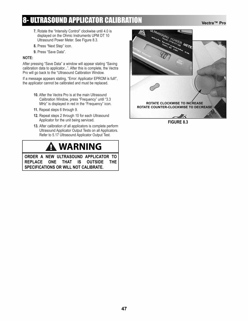
7. Rotate the “Intensity Control” clockwise until 4.0 is displayed on the Ohmic Instruments UPM DT 10 Ultrasound Power Meter. See Figure 8.3.
8. Press “Next Step” icon.9. Press “Save Data”.
NOTE:After pressing “Save Data” a window will appear stating “Savingcalibration data to applicator...”. After this is complete, the VectraPro will go back to the “Ultrasound Calibration Window.If a message appears stating, “Error: Applicator EPROM is full!”,the applicator cannot be calibrated and must be replaced.
10. After the Vectra Pro is at the main Ultrasound Calibration Window, press “Frequency” until “3.3 MHz” is displayed in red in the “Frequency” icon.
11. Repeat steps 6 through 9.12. Repeat steps 2 through 10 for each Ultrasound
Applicator for the unit being serviced.13. After calibration of all applicators is complete perform
Ultrasound Applicator Output Tests on all Applicators.Refer to 5.17 Ultrasound Applicator Output Test.
Vectra™ Pro
47
WARNING!ORDER A NEW ULTRASOUND APPLICATOR TOREPLACE ONE THAT IS OUTSIDE THESPECIFICATIONS OR WILL NOT CALIBRATE.
8- ULTRASOUND APPLICATOR CALIBRATION
FIGURE 8.3
ROTATE CLOCKWISE TO INCREASEROTATE COUNTER-CLOCKWISE TO DECREASE

Vectra™ Pro
48
9.1 General
A. Technical Maintenance Schedule1. The Service Tests found in Section 5 Troubleshooting
should be performed at least annually from the first date each Vectra Pro unit was placed into service. These tests will verify that the equipment is operating within OEM Specifications.
2. Use the Maintenance/Troubleshooting Test Data Sheetto record all test results for a particular unit when performing Technical Maintenance, Ultrasound Calibration and/or Troubleshooting.
3. Should it be necessary or desired to have the factory perform annual calibration and technical maintenance, contact the Chattanooga Group, Inc Service Department.
4. Should it become necessary to send the unit to the factory for repair after Troubleshooting has been performed, send a copy of the completed Maintenance/Troubleshooting Test Data Sheet for the particular unit requiring factory service. This information is essential to the Service Department in repairing and sending the unit back in a timely fashion.
5. Find the Maintenance/Troubleshooting Test Data Sheet at the end of this section. You may copy this as necessary to record data for the Vectra Pro units.
9- TECHNICAL MAINTENANCE
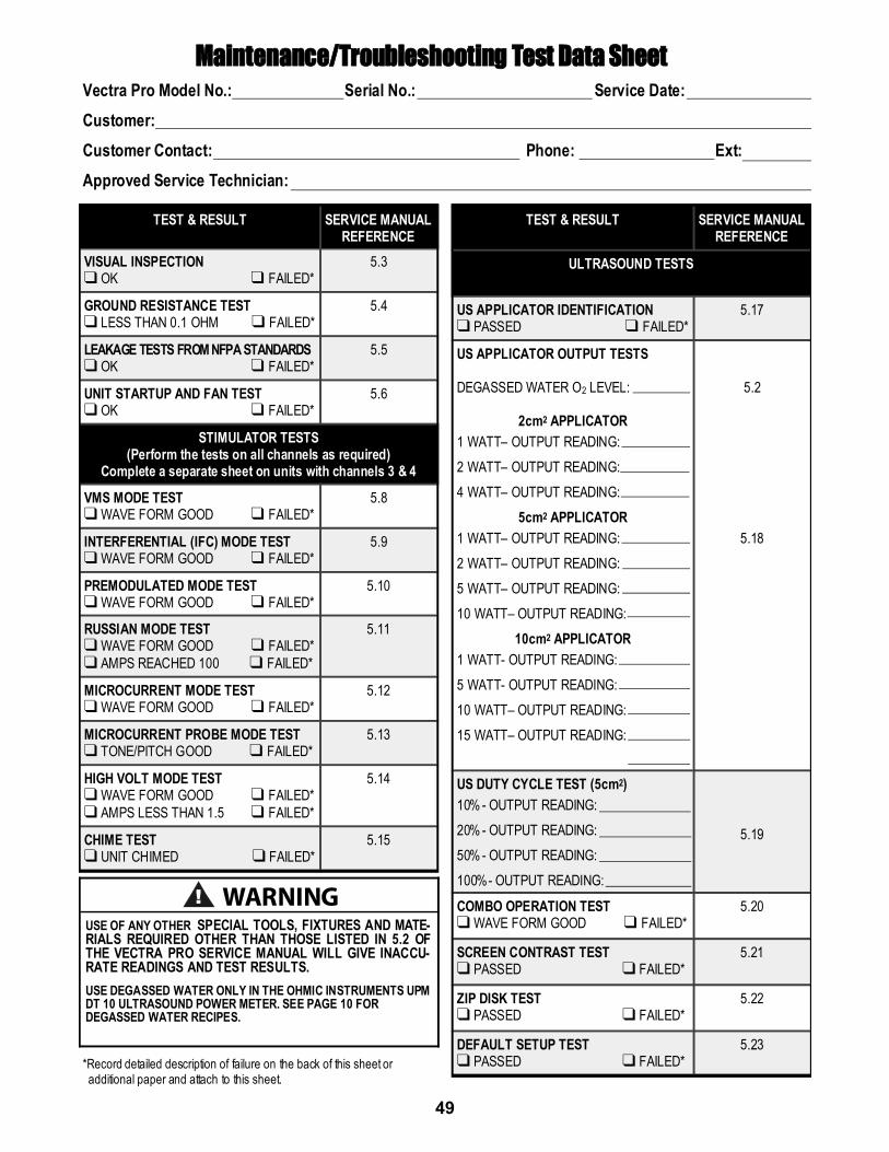
49
MMaaiinntteennaannccee//TTrroouubblleesshhoooottiinngg TTeesstt DDaattaa SShheeeett Vectra Pro Model No.: Serial No.: Service Date: Customer: Customer Contact: Phone: Ext: Approved Service Technician:
TEST & RESULT SERVICE MANUAL REFERENCE
VISUAL INSPECTION ❑ OK ❑ FAILED*
5.3
GROUND RESISTANCE TEST ❑ LESS THAN 0.1 OHM ❑ FAILED*
5.4
LEAKAGE TESTS FROM NFPA STANDARDS ❑ OK ❑ FAILED*
5.5
UNIT STARTUP AND FAN TEST ❑ OK ❑ FAILED*
5.6
STIMULATOR TESTS (Perform the tests on all channels as required)
Complete a separate sheet on units with channels 3 & 4
VMS MODE TEST ❑ WAVE FORM GOOD ❑ FAILED*
5.8
INTERFERENTIAL (IFC) MODE TEST ❑ WAVE FORM GOOD ❑ FAILED*
5.9
PREMODULATED MODE TEST ❑ WAVE FORM GOOD ❑ FAILED*
5.10
RUSSIAN MODE TEST ❑ WAVE FORM GOOD ❑ FAILED* ❑ AMPS REACHED 100 ❑ FAILED*
5.11
MICROCURRENT MODE TEST ❑ WAVE FORM GOOD ❑ FAILED*
5.12
MICROCURRENT PROBE MODE TEST ❑ TONE/PITCH GOOD ❑ FAILED*
5.13
HIGH VOLT MODE TEST ❑ WAVE FORM GOOD ❑ FAILED* ❑ AMPS LESS THAN 1.5 ❑ FAILED*
5.14
CHIME TEST ❑ UNIT CHIMED ❑ FAILED*
5.15
TEST & RESULT SERVICE MANUAL REFERENCE
ULTRASOUND TESTS
US APPLICATOR IDENTIFICATION ❑ PASSED ❑ FAILED*
5.17
US APPLICATOR OUTPUT TESTS DEGASSED WATER O2 LEVEL:
2cm2 APPLICATOR 1 WATT– OUTPUT READING: 2 WATT– OUTPUT READING: 4 WATT– OUTPUT READING:
5cm2 APPLICATOR 1 WATT– OUTPUT READING: 2 WATT– OUTPUT READING: 5 WATT– OUTPUT READING: 10 WATT– OUTPUT READING:
10cm2 APPLICATOR 1 WATT- OUTPUT READING: 5 WATT- OUTPUT READING: 10 WATT– OUTPUT READING: 15 WATT– OUTPUT READING:
5.2
5.18
US DUTY CYCLE TEST (5cm2) 10% - OUTPUT READING: 20% - OUTPUT READING: 50% - OUTPUT READING: 100%- OUTPUT READING:
5.19
COMBO OPERATION TEST ❑ WAVE FORM GOOD ❑ FAILED*
5.20
SCREEN CONTRAST TEST ❑ PASSED ❑ FAILED*
5.21
ZIP DISK TEST ❑ PASSED ❑ FAILED*
5.22
DEFAULT SETUP TEST ❑ PASSED ❑ FAILED*
5.23
! WARNING USE OF ANY OTHER SPECIAL TOOLS, FIXTURES AND MATE-RIALS REQUIRED OTHER THAN THOSE LISTED IN 5.2 OF THE VECTRA PRO SERVICE MANUAL WILL GIVE INACCU-RATE READINGS AND TEST RESULTS. USE DEGASSED WATER ONLY IN THE OHMIC INSTRUMENTS UPM DT 10 ULTRASOUND POWER METER. SEE PAGE 10 FOR DEGASSED WATER RECIPES.
*Record detailed description of failure on the back of this sheet or additional paper and attach to this sheet.

Vectra™ Pro
40

Vectra™ Pro
41

AAcchhiieevveerr™™
SupportsAAddaappttaa®®
Treatment TablesAA..EE..RR..®® BBoooott
Auto Edema Reduction BootCCaammbbiioonn®®
Shock Dampening Foot Care ProductsCCaarrppaall--TTrraacc™™
Carpal Traction AccessoryCCeerrvviiccaall TTrraaccttiioonn SSyysstteemm
Clinical Cervical TractionCCoollPPaaCC®®
Chilling Units and Reusable ColdTherapy Products
CCoonndduuccttoorr™™ GGeellHighly Conductive Ultrasound Gel
CCoonnttrraaccttuurree PPrroodduuccttssContracture Management OrthoticProducts
CCTTSS®®
Carpal Tunnel Stretching DeviceDDUURRAA--SSTTIICCKK®® EElleeccttrrooddeess
Self-Adhesive ElectrodesEEMMGG RReettrraaiinneerr®®
Dual Channel Surface EMGFFlleexxii--PPAACC®® II aanndd IIII
Reusable Hot and Cold CompressesFFlluuiiddootthheerraappyy®®
Dry Heat Whirlpool Therapy UnitsGGeell MMeeddeexx™™
Gel Mattress OverlayHHyyddrrooccoollllaattoorr®®
Heating Units and HotPacs™IInntteelleecctt®® LLeeggeenndd
Ultrasound and ElectrotherapyProducts
MMeeaassuurreemmeenntt IInnssttrruummeennttssDynamometers, Goniometers, etc.
MMyyoossssaaggee®®
Massage LotionNNyyllaatteexx®®
Elastic WrapsOOppttiiFFlleexx®®
Continuous Passive MotionPPaarraa--CCaarree®®
Paraffin Wax UnitPPiillllooww PPeerrffeecctt™™
Cervical Pillow LinePPiivvoottaall TThheerraappyy SSyysstteemm™™
Orthotics for the SpinePPrrooPPoowweerr PPiillllooww™™
Power Massage PillowPPrreessSSssiioonn®®
Intermittent CompressionPPrroonn PPiilllloo®®
Positioning PillowSSPPOORRTT--PPAACC™™
Soccer Ball Shaped Cold PackTThheerrmmaa--WWrraapp™™
Hot and Cold CompressionTTrriittoonn®®
Treatment and Traction EquipmentTTXX®®
Treatment and Traction EquipmentVVeeccttrraa™™ SSeerriieess
Electrotherapy products.WWeellllnneessss 11sstt™™
Back SupportWWoommeenn’’ss CCoonnttoouurr BBaacckk SSuuppppoorrtt
Back SupportHHAANNDDIISSIIZZEERR™™
Hand ExersiserVVeerrssaaBBaatthh SSeeaatt™™
Aid to Daily Living
MMoorree TTrruusstteedd PPrroodduuccttss ffrroomm CChhaattttaannooooggaa GGrroouupp,, IInncc..
ISO 9001 CERTIFIED4717 Adams RoadP.O. Box 489Hixson, TN 37343 U.S.A.1-423-870-22811-800-592-7329 U.S.A.1-800-361-6661 CANADA+ 1-423-870-2046 OUTSIDE U.S.A. FAXwww.chattgroup.com
© 2001 Chattanooga Group, Inc.Part Number: 79607A