service bulletin n° 109sp-144 alert date
TRANSCRIPT

N° 109SP-144 DATE: April 26, 2021
REV. : / - March 15, 2017
Page 1 of 33
TITLE
ATA 64 - INSPECTION OF TAIL ROTOR SHAFT ASSY P/N 109-0445-08-(ALL DASHES) AND TAIL ROTOR SLEEVE ASSY P/N 109-0130-90-121
REVISION LOG
New Issue
An appropriate entry should be made in the aircraft log book upon accomplishment.If ownership of aircraft has changed, please, forward to new owner.
Leonardo S.p.A.Via Giovanni Agusta, 52021017 Cascina Costa di Samarate (VA) ItalyTel.: +39 0331 229111 - Fax: +39 0331 229605/222595
ALERT
SERVICE BULLETIN

S.B. N°109SP-144 ALERT DATE: April 26, 2021 Page 2 of 33 REVISION: /
1. PLANNING INFORMATION
A. EFFECTIVITY
All the Leonardo S.p.a. AW109SP helicopters installing a TR sleeve assy P/N 109-0130-
90-121 with S/Ns MO.001 to S/N MO.677 and with S/N MOR678 to MOR1140.
B. COMPLIANCE
NOTE
TR sleeve assy P/N 109-0130-90-121 marked with letter
“R” after S/N are not affected by Part II and Part III.
Part I:
Within and not later than 25 flight hours or 3 months whichever occurs first after the
issue of this Service Bulletin.
Part II:
Every 25 flight hours after accomplishment of part I and until application of Part III of this
Service Bulletin or until installation of a non affected sleeve.
Part III:
At any bushing replacement.
Part IV:
In conjunction with every 400 FH scheduled inspection after application of Part I of this
Service Bulletin until next TGB overhaul or TGB special inspection (1600 FH).
C. CONCURRENT REQUIREMENTS
N.A.
D. REASON
This Service Bulletin is issued in order to provide the necessary instruction on how to
perform a detailed inspection of tail rotor shaft assy P/N 109-0445-08-(all dashes) and
tail rotor sleeve assy P/N 109-0130-90-121.
E. DESCRIPTION
During tail rotor system inspections required after an abnormal vibration event, an
extensive crack has been found on the tail rotor mast of an A109E helicopter at the
interface with the tail rotor sleeve. In order to assure the airworthiness of the fleet and
to collect data for the investigation, LH decided to issue this SB to perform (Part I) a tail
rotor and mast visual inspection together with a dye penetrant fluorescent liquid
inspection in the area potentially affected by the issue and (Part II) a recurrent check for

S.B. N°109SP-144 ALERT DATE: April 26, 2021 REVISION: / Page 3 of 33
condition of the TR sleeve bushing. In case of sleeve bushing debonding is found,
instructions are given to replace it (Part III). Part IV provides instruction to restore, if
necessary, solid lubricant protection on the area inspected with dye penetrant
fluorescent liquid.
F. APPROVAL
The technical content of this Service Bulletin is approved under the authority of DOA nr.
EASA.21.J.005. For helicopters registered under other Aviation Authorities, before
applying the Service Bulletin, applicable Aviation Authority approval must be checked
within Leonardo Helicopters customer portal.
EASA states mandatory compliance with inspections, modifications or technical
directives and related time of compliance by means of relevant Airworthiness Directives.
If an aircraft listed in the effectivity embodies a modification or repair not LHD certified
and affecting the content of this Service Bulletin, it is responsibility of the
Owner/Operator to obtain a formal approval by Aviation Authority having jurisdiction on
the aircraft, for any adaptation necessary before incorporation of the present Service
Bulletin.
G. MANPOWER
To comply with this Service Bulletin, the following MMH are deemed necessary:
Part I: 5 (five) MMH;
Part II: 0,5 (half an hour) MMH;
Part III: 4 (four) MMH (without considering the adhesive curing time);
Part IV: 0,25 (a quarter of hour) MMH.
MMH are based on hands-on time and can change with personnel and facilities
available.
H. WEIGHT AND BALANCE
N.A.
I. REFERENCES
1) PUBLICATIONS
DATA MODULE DESCRIPTION PART
DM01 0B-A-00-20-00-00A-120A-A Helicopter Safety - Pre-operation I, II, III
DM02 0B-B-64-00-00-00A-520A-A Tail rotor - Remove procedure I, II, III
DM03 0B-B-64-00-00-00A-720A-A Tail rotor - Install procedure I, II, III

S.B. N°109SP-144 ALERT DATE: April 26, 2021 Page 4 of 33 REVISION: /
DATA MODULE DESCRIPTION PART
DM04 0B-A-64-31-00-00A-520A-A Rotating control installation - Components - Remove procedure
I, II, III
DM05 0B-A-64-31-00-00A-720A-A Rotating control installation - Components - Install procedure
I, II, III
DM06 0B-A-64-31-00-00A-281B-B Rotating control installation - Components - Scheduled inspection
I, II
DM07 0B-A-65-21-01-00A-520A-A 90-degree gearbox - Remove procedure
I
DM08 0B-A-65-21-01-00A-720A-A 90-degree gearbox - Install procedure
I
DM09 0B-A-12-42-00-00A-730A-A External hydraulic power -
Connect procedure
I, II
DM10 0B-A-12-42-00-00A-510A-A External hydraulic power - Disconnect procedure
I, II
DM11 0B-A-67-21-00-00A-271C-A Tail rotor control system - Adjust II
DM12 0B-A-67-21-00-00A-271D-A Tail rotor control system - Adjust II
DM13 CPCP 20-70-10 Application of solid lubricant film IV
2) ACRONYMS
AMDI Aircraft Material Data Information
AMP Aircraft Maintenance Publication
AR As Required
CPCP Corrosion Protection and Control Publication
DOA Design Organization Approval
IPD Illustrated Parts Data
ITEP Illustrated Tool and Equipment Publication
LHD Leonardo Helicopters
MMH Maintenance Man Hours
P/N Part Number
SB Service Bulletin
3) ANNEX
Annex A AW109 TR shaft localized penetrant inspection Type 1, Method C, Level
2, Form “d”.
Annex B AW109 TR sleeve assy bushing replacement.
Annex C S.B. N°109SP-144 Inspection form.
J. PUBLICATIONS AFFECTED
N.A.

S.B. N°109SP-144 ALERT DATE: April 26, 2021 REVISION: / Page 5 of 33
K. SOFTWARE ACCOMPLISHMENT SUMMARY
N.A.

S.B. N°109SP-144 ALERT DATE: April 26, 2021 Page 6 of 33 REVISION: /
2. MATERIAL INFORMATION
A. REQUIRED MATERIALS
1) PARTS
PART I
N.A.
PART II
N.A.
PART III
# P/N ALTERNATIVE P/N DESCRIPTION Q.TY LVL NOTE LOG P/N
1 109-0133-07-101 Bushing 1 . -
PART IV
N.A.
Refer also to IPD for the spares materials required to comply with the AMP DMs
referenced in the accomplishment instructions.
2) CONSUMABLES
The following consumable materials, or equivalent, are necessary to accomplish this
Service Bulletin:
# Spec./LHD code number DESCRIPTION Q.TY NOTE PART
2 SAE-AMS-2644, Type I,
Method C, Level 2 Dye Penetrant AR (1)(2) I
3 SAE-AMS-2644, Type I, Form “d” Developer AR (1)(2) I
4 SAE-AMS-2644 Cl II Solvent (C290) AR (1)(2) I
5 ASTM D740, Type I Methyl-ethyl-ketone (C511) AR (1) I, III
6 Commercial Plastic bristled brush AR (1) I
7 Commercial Aluminum adhesive tape AR (1) I
8 Commercial Small soft clean brush AR (1) I
9 Commercial Clean, dry, lint-free cloth or
absorbent toweling AR (1) I
10 MIL-L-23398 Type IV Solid film, lubricant AR (1) I, IV
11 Commercial Aluminium oxide, 80-grit (C208) AR (1) III
12 199-05-002, Type II, Class 2 Adhesive, (C054) AR (1) III
13 Commercial Cloth, soft lint-free (C011) AR (1) III
14 MIL-PRF-680, Type II Cleaning solvent (C287) AR (1) III
Refer also to AMDI for the consumable materials required to comply with the AMP
DMs referenced in the accomplishment instructions.

S.B. N°109SP-144 ALERT DATE: April 26, 2021 REVISION: / Page 7 of 33
3) LOGISTIC MATRIX
N.A.
NOTE
Local supply.
This material shall be certified in accordance with AMS2644, obtained from a
supplier listed in QPL-AMS2644, supplied from the same manufacturer and in
aerosol cans packaging.
B. SPECIAL TOOLS
# P/N DESCRIPTION Q.TY NOTE PART
15 109-3130-32-1 Tail rotor retaining nut wrench (GF-56-00) 1 (B1) I
16 895-3130-02-101 Tool, T/R slider bushing installation
(GF-89-00) 1 (B1) I
17 109-3130-53-111 Tool, T/R pitch change slider ring nut
removal/installation (GF-58-00) 1 (B1) I
18 109-3130-54-101 or
109-3130-54-111 Tool, T/R pitch change housing ring nut
removal/installation (GF-59-00) 1 (B1) I
19 109-3130-70-101 Tool, T/R pitch change housing duplex
bearing removal (GF-63-00) 1 (B1) I
20 109-3130-69-101 Tool, T/R pitch change housing duplex
bearing installation (GF-62-00) 1 (B1) I
21 109-3130-71-101 Tool, T/R pitch change slider installation
(GF-64-00) 1 (B1) I
22 109-3130-55-117 Tool, T/R pitch change slider removal
(GF-66-00) 1 (B1) I
23 Commercial Endoscope 1 (B2)(B2) I
24 Commercial Dark curtain 1 (B2) I
25 Commercial Magnifying lens 5x 1 (B2) I
26 Commercial UV-A inspection lamp 1 (B2)(B3) I
27 Commercial UV-A/White light meters 1 (B2) I
28 Commercial Hydraulic system test bench 1 (B2) I, II
29 Metal sheet 55x5 mm,
thickness 1 mm. Bushing displacement
measuring tool 1 (B4)(B5) I, II
30 Commercial Environmental thermometer 1 (B2) I
31 Commercial Parallel lathe 1 (B2) III
32 Commercial Caliper 1 (B2) III
33 Commercial Dry abrasive blasting equipment 1 (B2) III
Refer to ITEP for the special tools required to comply with the AMP DMs referenced in
the accomplishment instructions.
Refer also to Annex A for the equipment/tools required for the liquid penetrant
inspection.
Refer also to Annex B for the equipment/tools required for the sleeve assy bushing
replacement.

S.B. N°109SP-144 ALERT DATE: April 26, 2021 Page 8 of 33 REVISION: /
SPECIAL TOOLS NOTE
Please contact Leonardo Helicopters Division order administration to request the
tools supply on loan. As soon as the present Service Bulletin is implemented the
tools supplied on loan shall be promptly returned to Leonardo Helicopters Division.
Item to be procured as local supply.
This lamp should emit at least 1200 µW/cm² and no more than 20lux at 38cm from
the front of the filter to the face of the sensor.
Local manufacturing in accordance instructions given in Part I.
The metal sheet specifications may be different. For reference, some examples are
given: 2024 T3 AMS-QQ-A-250/4; 2024 T3 AMS-QQ-A-250/5; CRES 301 ¼ H,
AMS5517.
C. INDUSTRY SUPPORT INFORMATION
Owners/Operators who comply with the instructions of this Service Bulletin no later than
the applicable date in the “Compliance” section will be eligible to receive REQUIRED
MATERIALS on free of charge basis, except for Consumable Materials and Special
Tools.
NOTE 1: Customers who fail to comply with the instructions in this Service Bulletin
before the compliance date are not eligible for the aforementioned special policy.
Please Issue relevant MMIR form to your Warranty Administration Dpt accompanied by
INSPECTION REPORT and PICTURE of the affected area.
NOTE 2: The INSPECTION REPORT and PICTURE are mandatory; in case the MMIR
is not accompanied by these documents, it will be rejected.

S.B. N°109SP-144 ALERT DATE: April 26, 2021 REVISION: / Page 9 of 33
3. ACCOMPLISHMENT INSTRUCTIONS
GENERAL NOTES
a) Place an identification tag on all components that
are re-usable, including the attaching hardware that
has been removed to gain access to the modification
area and adequately protect them until their later re-
use.
b) All lengths are in mm.
PART I
1. In accordance with AMP DM 0B-A-00-20-00-00A-120A-A, prepare the helicopter on
ground for a safe maintenance. Disconnect the battery, all electrical power sources and/or
the external power supply.
2. Gain access to the plug P/N 109-0133-18-103 installed on the tail rotor hub removing
balance flange and all the necessary components. Mark the installation position of the
balance masses in order to reinstall them in the same location and reduce time for the TR
balancing required at the end of the reassembly. Retain all the components.
3. In accordance with Figure 3, verify that plug P/N 109-0133-18-103 is torqued at 59÷69
Nm.
3.1 Record the torque value on the annexed Detailed Inspection Form and proceed
with next step.
4. In accordance with AMP DM 0B-B-64-00-00-00A-520A-A, remove the tail rotor hub and
blade assy.
NOTE
Before the removal of the TR sleeve as per AMP DM
0B-A-64-31-00-00A-520A-A, check the bushing P/N
109-0133-07-101 for condition and bonding. In case it is
found partially or completely displaced from its seat,
before and after its removal, take pictures of bushing
and sleeve, record the finding on the Detailed Inspection
Form and proceed with the following step.
5. In accordance with AMP DM 0B-A-64-31-00-00A-520A-A, remove the pitch change
mechanism.
6. In accordance with AMP DM 0B-A-64-31-00-00A-281B-B, inspect the removed tail rotor
sleeve assy P/N 109-0130-90-121 and bushing P/N 109-0133-07-101. Inspect the bushing
in the tail rotor sleeve assy for debonding.

S.B. N°109SP-144 ALERT DATE: April 26, 2021 Page 10 of 33 REVISION: /
6.1 In case anomalies are detected, take pictures of the affected bushing and sleeve,
record the findings on the Detailed Inspection Form, and contact Leonardo
Helicopters to evaluate part serviceability. If necessary, in accordance with AMP
DM 0B-A-64-31-00-00A-720A-A, replace it with a serviceable TR Sleeve. In the
meantime, proceed with step 7.
6.2 In case of no findings, proceed to next step.
7. With reference to Figure 1 and Figure 2 detail A, gain access to tail rotor shaft assy P/N
109-0445-08-(all dashes) and:
CAUTION
Pay particular attention to not damage the Tail Rotor
Shaft Assy with the endoscope probe during the
inspection.
7.1 perform internal surface endoscope inspection for abnormal wear condition,
corrosion, fretting, crack and damage;
7.2 perform external surface visual inspection for abnormal wear condition, corrosion,
fretting, crack and damage;
7.3 with reference to Figure 1 and Figure 2 detail B, in accordance with Annex A,
perform surface Fluorescent Penetrant Inspection on the indicated area;
7.4 if no evidence of existing anomalous wear, corrosion, fretting, damage or crack is
found, proceed to step 8;
7.5 if evidence of anomalous wear, corrosion, fretting, damage or crack is found, take
relevant pictures, record the findings on the Detailed Inspection Form and contact
Leonardo Helicopters to evaluate part serviceability. If necessary, in accordance
with AMP DMs 0B-A-65-21-01-00A-520A-A and 0B-A-65-21-01-00A-720A-A,
replace it with a serviceable 90-Degree Gearbox.
NOTE
Do not attach aft boot to pitch change slider assy.
8. In accordance with AMP DM 0B-A-64-31-00-00A-720A-A, re-install previously removed
pitch change mechanism.
9. In accordance with AMP DM 0B-B-64-00-00-00A-720A-A, re-install previously removed
tail rotor hub and blade assy.
10. In accordance with AMP DM 0B-A-12-42-00-00A-730A-A, connect the hydraulic test
bench to the helicopter and operate it at 103.5 bar (1500 psi).
CAUTION
One assistant must position and hold right anti torque
pedal full forward before beginning the following

S.B. N°109SP-144 ALERT DATE: April 26, 2021 REVISION: / Page 11 of 33
procedure.
11. In accordance with Figure 4, manufacture on site the bushing displacement measuring
tool following the next steps:
11.1 Starting from a metal sheet of 55x5 mm (1 mm thickness), bend it to obtain an “L”
shape with the size indicated in Figure 4.
11.2 In accordance with Figure 4 Detail E, insert the tool between pitch change slider
assy and tail rotor shaft assy until reaching the bushing of the TR sleeve assy.
CAUTION
After trimming, remove all swarf and sharp edges to
avoid to scratch the tail rotor shaft assy.
11.3 If gap is present between the vertical leg of the tool and the pitch change slider
assy, start trimming the short segment until gap is removed.
11.4 Record the dimension of the tool and retain it for Part II inspection.
12. With reference to Figure 3, attach aft boot P/N 109-0130-96-101 on pitch change slider
assy.
13. Return the anti torque pedal to center. In accordance with AMP DM 0B-A-12-42-00-00A-
510A-A, disconnect the hydraulic test bench from the helicopter.
14. Return the helicopter to a ready to flight condition and record for compliance with Part I of
this Service Bulletin on the helicopter logbook.
NOTA
Send the Detailed Inspection Form and pictures with
Subject line “ASB 109SP-144 - S/N XXXXX –
Compliance to Part I”. “XXXXX” is the helicopter S/N.
15. Send the attached compliance form and the pictures taken during the inspections to the
following mail box:
As an alternative, gain access to My Communications section on Leonardo WebPortal and
compile the “Service Bulletin Application Communication”.

S.B. N°109SP-144 ALERT DATE: April 26, 2021 Page 12 of 33 REVISION: /
PART II
NOTE
If tail rotor controls adjust procedure (ref. 0B-A-67-21-
00-00A-271C-A or 0B-A-67-21-00-00A-271D-A) has
been performed after manufacturing the Bushing
displacement measuring tool, discard the previous tool
and manufacture a new one i.a.w. Part I, step 11.
1. In accordance with AMP DM 0B-A-00-20-00-00A-120A-A, prepare the helicopter on
ground for a safe maintenance. Disconnect the battery, all electrical power sources and/or
the external power supply.
2. In accordance with AMP DM 0B-A-12-42-00-00A-730A-A, connect the hydraulic test
bench to the helicopter and operate it at 103.5 bar (1500 psi).
CAUTION
One assistant must position and hold right anti torque
pedal full forward before beginning the following
procedure.
3. With reference to Figure 3, detach aft boot from pitch change slider assy.
4. With reference to Figure 4, move aft boot and, using bushing displacement measuring
tool, verify that the distance from bushing to pitch change slider assy has not changed
since last inspection. If the distance decreases (long side of tool not in contact with slider
assy, ref. Figure 4 Detail E), proceed as follows, otherwise proceed to step 5:
4.1 In accordance with AMP DM 0B-A-12-42-00-00A-510A-A, disconnect the hydraulic
test bench from the helicopter.
4.2 Gain access to the plug P/N 109-0133-18-103 installed on the tail rotor hub
removing balance flange and all the necessary components. Mark the installation
position of the balance masses in order to reinstall them in the same location and
reduce time for the TR balancing required at the end of the reassembly. Retain all
the components.
4.3 In accordance with Figure 3, verify that plug P/N 109-0133-18-103 is torqued at
59÷69 Nm.
4.4 Record the torque value on the Detailed Inspection Form and proceed with next
step.
4.5 In accordance with AMP DM 0B-B-64-00-00-00A-520A-A, remove the tail rotor hub
and blade assy.
4.6 In accordance with AMP DM 0B-A-64-31-00-00A-520A-A, remove the pitch
change mechanism.

S.B. N°109SP-144 ALERT DATE: April 26, 2021 REVISION: / Page 13 of 33
4.7 On the tail rotor sleeve assy P/N 109-0130-90-121 before its removal, inspect the
bushing P/N 109-0133-07-101 for correct installation and debonding
4.7.1 In case the bushing is not found in the correct position or it is debonded
so that can be moved off from its seat, take pictures of the bushing and
sleeve, record the findings on the Detailed Inspection Form and replace
the bushing in accordance with part III. If necessary, in accordance with
AMP DM 0B-A-64-31-00-00A-720A-A, replace the TR sleeve with a
serviceable part.
4.7.2 In case of no findings, verify the bushing displacement measuring tool
as per Part I, step 11.
4.8 In accordance with AMP DM 0B-A-64-31-00-00A-720A-A, re-install previously
removed pitch change mechanism.
4.9 In accordance with AMP DM 0B-B-64-00-00-00A-720A-A, re-install previously
removed tail rotor hub and blade assy. Proceed to step 7.
5. With reference to Figure 3, attach aft boot P/N 109-0130-96-101 on pitch change slider
assy.
6. Return anti torque pedal to center. In accordance with AMP DM 0B-A-12-42-00-00A-510A-
A, disconnect the hydraulic test bench from the helicopter.
7. Return the helicopter to a ready to flight condition and record for compliance with Part II
of this Service Bulletin on the helicopter logbook.
NOTA
Send the Detailed Inspection Form and pictures with
Subject line “ASB 109SP-144 - S/N XXXXX –
Compliance to Part II”. “XXXXX” is the helicopter S/N.
8. Send the attached compliance form and the pictures taken during the inspections to the
following mail box:
As an alternative, gain access to My Communications section on Leonardo WebPortal and
compile the “Service Bulletin Application Communication”.

S.B. N°109SP-144 ALERT DATE: April 26, 2021 Page 14 of 33 REVISION: /
PART III
1. In accordance with AMP DM 0B-A-00-20-00-00A-120A-A, prepare the helicopter on
ground for a safe maintenance. Disconnect the battery, all electrical power sources and/or
the external power supply.
2. In accordance with AMP DM 0B-B-64-00-00-00A-520A-A, remove the tail rotor hub and
blade assy.
3. In accordance with AMP DM 0B-A-64-31-00-00A-520A-A, remove the pitch change
mechanism.
4. In accordance with Annex B, replace the bushing P/N 109-0133-07-101.
5. In accordance with AMP DM 0B-A-64-31-00-00A-720A-A, re-install previously removed
pitch change mechanism.
6. In accordance with AMP DM 0B-B-64-00-00-00A-720A-A, re-install previously removed
tail rotor hub and blade assy.
7. Return the helicopter to a ready to flight condition and record for compliance with Part III
of this Service Bulletin on the helicopter logbook.
8. Send the attached compliance form to the following mail box:
As an alternative, gain access to My Communications section on Leonardo WebPortal and
compile the “Service Bulletin Application Communication”.

S.B. N°109SP-144 ALERT DATE: April 26, 2021 REVISION: / Page 15 of 33
PART IV
1. During application of tail rotor gearbox 400 FH scheduled inspection, with reference to
Figure 2 Detail B, verify the presence of solid film lubricant on “inspection area” (it should
be present only on the “4.0mm section” and on vertical side of shoulder). If necessary,
restore the layer of solid film lubricant MIL-L-23398 Type IV as follows:
1.1 Mask off surrounding areas near the inspection zone (Figure 2, Detail B) with
adhesive Aluminium tape.
1.2 Clean the part with a clean cloth soaked with Class 2 solvent listed in QPL-AMS-
2644.
1.3 In accordance with CPCP 20-70-10, touch up where necessary with solid film
lubricant with MIL-L-23398 Type IV product.
2. Record for compliance with Part IV of this Service Bulletin on the helicopter logbook.
3. Send the attached compliance form to the following mail box:
As an alternative, gain access to My Communications section on Leonardo WebPortal and
compile the “Service Bulletin Application Communication”.
Non cancellare mai questo segnalibro Non cancellare mai interruzione sezione

Figure 1 S.B. N°109SP-144 ALERT DATE: April 26, 2021 Page 16 of 33 REVISION: /

Figure 2 S.B. N°109SP-144 ALERT DATE: April 26, 2021 REVISION: / Page 17 of 33

Figure 3 S.B. N°109SP-144 ALERT DATE: April 26, 2021 Page 18 of 33 REVISION: /
ROTATION
109-0133-18-103 PLUG (REF)TORQUE 59÷69 Nm
VIEW C
TAIL ROTOR INSTALLATIONSTRUCTURE AND SYSTEMS ARE PARTIALLY OMITTED FOR BETTER CLARITY PURPOSE
VIEW CSTRUCTURE AND SYSTEMS ARE PARTIALLY OMITTED
FOR BETTER CLARITY PURPOSE
109-0130-90-117/-121TR SLEEVE ASSY (REF)
109-0130-98-101 AFT BOOT (REF)
109-0130-91-(ALL DASHES)PITCH CHANGE SLIDER ASSY (REF)
REF
DETAIL D

Figure 4 S.B. N°109SP-144 ALERT DATE: April 26, 2021 REVISION: / Page 19 of 33
TRIM AREA
DETAIL ESTRUCTURE AND SYSTEMS ARE PARTIALLY OMITTED
FOR BETTER CLARITY PURPOSE
109-0130-91-(ALL DASHES)PITCH CHANGE SLIDER ASSY (REF)
DETAIL DSTRUCTURE AND SYSTEMS ARE PARTIALLY OMITTED
FOR BETTER CLARITY PURPOSE
109-0130-90-117/-121TR SLEEVE ASSY (REF)109-0133-07-101
BUSHING (REF)
BUSHING DISPLACEMENTMEASURING TOOL
POINT OF CONTACT
DETAIL E
BUSHING DISPLACEMENT MEASURING TOOL
40 m
m (
RE
F)
15 mm (REF)

ANNEX A
S.B. N°109SP-144 ALERT DATE: April 26, 2021 Page 20 of 33 REVISION: /
ANNEX A
AW109 TR SHAFT LOCALIZED
PENETRANT INSPECTION
TYPE 1, METHOD C, LEVEL 2, FORM “d”

ANNEX A
S.B. N°109SP-144 ALERT DATE: April 26, 2021 REVISION: / Page 21 of 33
1 PURPOSE AND APPLICABILITY
This procedure details the requirements for the Liquid Penetrant Inspection (PT) on the
Tail Rotor Shaft Assy. The specific Penetrant system to be used is Type I, Method C,
Sensitivity Level 2, form “d”. Purpose of this inspection is the detection of any possible
crack located on a specific surface of the tail rotor shaft assy.
2 REFERENCES
The following documents in their last revision are considered part of this procedure:
ASTM E1417 Standard Practice for Liquid Penetrant Testing;
ASTM E3022 Standard Practice for Measurement of Emission Characteristics and
Requirements for LED UV-A Lamps Used in Fluorescent Penetrant
and Magnetic Particle Testing;
EN4179/NAS410 Qualification and approval of personnel for non-destructive testing;
QPL AMS2644 Qualified Product List of Inspection Materials, Penetrant;
SAE AMS2644 Inspection Materials, Penetrant.
3 EQUIPMENT AND MATERIALS
The following materials, equipment and tools are requested.
3.1 MATERIALS
WARNING
SOLVENT CLEANERS AND DEVELOPER CARRIER
FLUIDS ARE DANGEROUS. OBSERVE ALL
RELEVANT SAFETY PRECAUTIONS TO PREVENT
THE RISK OF INJURY, FIRE OR EXPLOSION.
a. Dye Penetrant SAE-AMS-2644 TY I, Method C, Level 2 (*);
b. Developer SAE-AMS-2644 Form “d” (*);
c. Solvent SAE-AMS-2644 Class 2 (*).
d. Methyl Ethyl Ketone (MEK) solvent.
(*) All the materials shall be certified in accordance with AMS2644, obtained from a
supplier listed in QPL-AMS2644, supplied from the same manufacturer and in
aerosol cans packaging.
3.2 EQUIPMENT/TOOLS
a. dark curtain;
b. UV-A inspection lamp emitting at least 1200 µW/cm² and no more than 20lux at
38cm from the front of the filter to the face of the sensor;

ANNEX A
S.B. N°109SP-144 ALERT DATE: April 26, 2021 Page 22 of 33 REVISION: /
c. UV-A/White light meters;
d. plastic bristled brush;
e. small soft clean brush;
f. aluminum adhesive tape;
g. clean, dry, lint-free cloth or absorbent toweling;
h. a magnification lens (max 5X);
i. an environmental thermometer.
4 PERSONNEL
All Personnel performing this inspection and reporting results shall be approved to the
appropriate level in accordance with EN4179/NAS410, or equivalent. The personnel shall
also be familiar with the purpose of this procedure.
5 INSPECTION INSTRUCTION
5.1 PART PREPARATION
Make sure that the temperature of the part to be inspected is between 10°C and
45°C degrees (50-113 Fahrenheit).
WARNING
USE OF ANY ABRASIVE MATERIALS OR TOOLS IS
STRICTLY FORBIDDEN.
Mask off surrounding areas near the inspection zone (Figure 2, Detail B) with
adhesive Aluminium tape and remove dry film lubricant using both MEK and plastic
bristled brush taking care to the area of the shoulder and related fillet radius.
Make sure that dry film lubricant is fully removed from all the inspection area and
that part surface is degreased and dry. Clean white paper can be used to prove the
complete removal of the dry film lubricant.
5.2 PENETRANT APPLICATION
NOTE
Do not spray the liquid penetrant directly on the
inspection area.
After the solvent (MEK) is completely evaporated, apply Type 1, Method C,
Sensitivity Level 2 liquid penetrant listed in QPL-AMS-2644 using a small soft clean
dry brush. Take care to cover all the inspection area (Figure 2, Detail B). Penetrant
Dwell Time shall be a minimum of 30 minutes and no more than 60 minutes.
5.3 PENETRANT REMOVAL

ANNEX A
S.B. N°109SP-144 ALERT DATE: April 26, 2021 REVISION: / Page 23 of 33
Excess penetrant removal shall be performed by using clean dry “lint free” cloths (or
paper). Darken the part and switch on UV-A light lamp to achieve irradiance not less
than 100 µW/cm² on the working surface and ambient white light illuminance not
exceeding 100 lx.
NOTE
The surface of the component shall not be flushed with
solvent and the cloth or towel shall not be saturated with
solvent.
Removal shall be performed by first wiping the excess penetrant with a clean, lint-
free, dry cloth or absorbent toweling and the remainder of the surface penetrant shall
then be removed with a solvent-dampened lint-free cloth or towel (solvent Class 2
listed in QPL-AMS-2644). The masking tape can be removed before using the
solvent-dampened cloth in order to achieve a better performance in excess
penetrant removal. The surface will dry immediately at completion of this phase.
5.4 DEVELOPING
CAUTION
In case of any developer dripping, the part shall be
carefully cleaned and the whole process repeated from
“Part Preparation”.
In case of exceeding 60 minutes, the part shall be
carefully cleaned and the whole process repeated from
“Part Preparation”.
Shake Nonaqueous Developer can for at least 30 seconds and spray form “d”
developer listed in QPL-AMS-2644 as a uniform thin coating over the entire
inspection area. A correct application will result in a layer that gives an insight into
the underlying metal. Development time shall be minimum 20 minutes and maximum
60 minutes.
5.5 EXAMINATION
Fluorescent Penetrant examination shall be carried out in conditions of subdued
background lighting (maximum illuminance 20 lux) using UV-A inspection light
source able to provide not less than 1200 µW/cm² at 38cm.
Inspector’s vision shall be dark adapted for a minimum of 1 min prior to examining
components.

ANNEX A
S.B. N°109SP-144 ALERT DATE: April 26, 2021 Page 24 of 33 REVISION: /
Inspectors shall not wear photochromic or permanently darkened lenses while
processing or reviewing parts under UV-A light.
The use of magnifying lens (5x) to support the interpretation of liquid penetrant
indications is recommended.
5.6 EVALUATION
In case any crack-like indication, considered as relevant indication, is found, contact
Leonardo Helicopters for instructions.
5.7 POST INSPECTION CLEANING
At the end of the inspection, in case of no finding, carefully clean the part from any
residual of the products used with a clean cloth soaked with Class 2 solvent listed in
QPL-AMS-2644.
In accordance with CPCP 20-70-10, restore solid film lubricant MIL-L-23398 Type
IV in the area of inspection.
6 RECORDS
Report the result of the inspection as necessary using pertinent documentation.

ANNEX B
S.B. N°109SP-144 ALERT DATE: April 26, 2021 REVISION: / Page 25 of 33
ANNEX B
AW109 TR SLEEVE ASSY
BUSHING REPLACEMENT

ANNEX B
S.B. N°109SP-144 ALERT DATE: April 26, 2021 Page 26 of 33 REVISION: /
1 PURPOSE AND APPLICABILITY
This procedure details the instructions to replace the bushing P/N 109-0133-07-101 of
the TR Sleeve Assy. This procedure has to be performed by qualified maintenance
personnel in authorized facilities.
2 EQUIPMENT AND MATERIALS
The following materials, equipment and tools are requested.
2.1 MATERIALS
WARNING
SOLVENT FLUID IS DANGEROUS. OBSERVE ALL
RELEVANT SAFETY PRECAUTIONS TO PREVENT
THE RISK OF INJURY, FIRE OR EXPLOSION.
a. Bushing P/N 109-0133-07-101;
b. Aluminium oxide, 80-grit (C208);
c. Adhesive 199-05-002, Type II, Class 2 (C054);
d. Cloth, soft lint-free (C011);
e. Cleaning solvent MIL-PRF-680, Type II (C287).
2.2 EQUIPMENT/TOOLS
a. Parallel lathe;
b. Caliper;
c. Dry abrasive blasting equipment;
3 INSPECTION INSTRUCTION
NOTE
The tail rotor sleeve assy P/N 109-0130-90-121 is
considered already removed from the helicopter as per
applicable AMP DM.
3.1 Put the tail rotor sleeve assy P/N 109-0130-90-121 on an applicable work table.
3.2 Visually examine the sleeve assy for damage. In case of evident signs of scratches,
puncture or gouges, replace it.
CAUTION
Be careful to not damage the seat of the bushing in the
sleeve.

ANNEX B
S.B. N°109SP-144 ALERT DATE: April 26, 2021 REVISION: / Page 27 of 33
NOTE
To decrease the thickness of the bushing, perform the
operation in different steps in order not to exceed the
internal diameter of 35.42 thru 35.52 mm.
NOTE
If a parallel lathe is not available, a screwdriver can be
used as alternative. Be careful not to damage the
sleeve.
3.3 Proceed to decrease the thickness of the bushing, in the sleeve, with a parallel
lathe to remove the bushing and the adhesive. Remove and discard the bushing.
NOTE
Use an applicable light source, a mirror and a scriber to
perform next step.
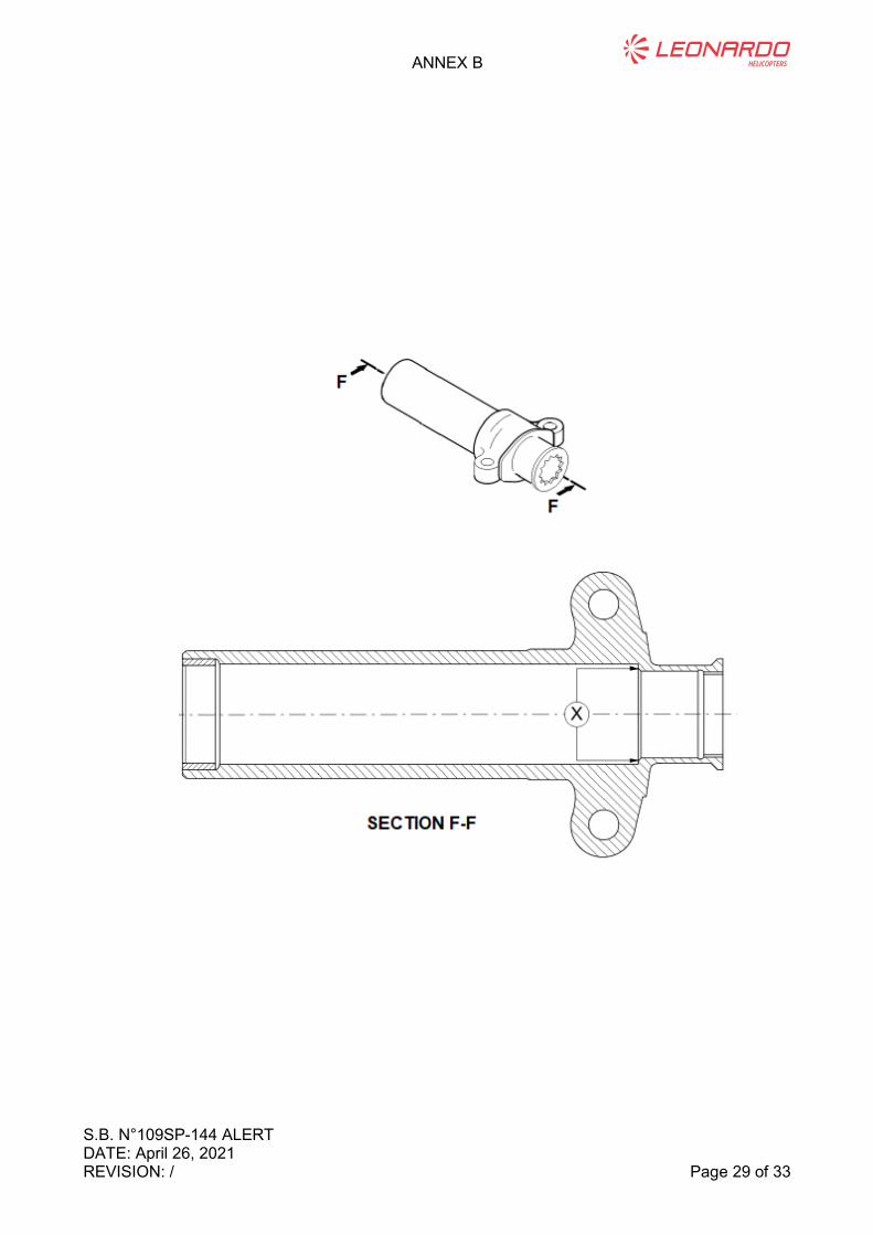
3.4 With reference to Figure B1, Detail F, examine the mating surface between the
sleeve and the tail rotor shaft assy (X Area), for wear and stepping. No wear or
stepping is permitted. In case of any doubt, clean with the cleaning solvent MIL-
PRF-680, Type II and perform again the inspection. If the presence of damage is
confirmed, replace the sleeve.
3.5 Verify that the internal diameter of the sleeve is 35.42 thru 35.52 mm.
3.6 Prepare the sleeve and the new bushing P/N 109-0133-07-101 for the bonding as
follows:
3.6.1 Clean the areas in contact of the sleeve and the bushing with vapour
degreasing procedure or with the solvent ASTM D740, Type I and the
cloth, soft lint-free.
3.6.2 Prepare the seat of the bushing in the sleeve with the dry abrasive
blasting procedure. To do this, use the Aluminium oxide, 80-grit at a
constant pressure of 345 thru 552 kPa.
3.6.3 Clean again the areas in contact of the sleeve and the bushing with
vapour degreasing procedure or with the solvent ASTM D740, Type I
and the cloth, soft lint-free.
CAUTION
You must apply the adhesive within 4 hours from the
cleaning.
3.6.4 Apply a thin film of the adhesive 199-05-002, Type II, Class 2 on the seat
of the bushing in the sleeve.
3.6.5 Put the bushing into its seat in the sleeve.

ANNEX B
S.B. N°109SP-144 ALERT DATE: April 26, 2021 Page 28 of 33 REVISION: /
3.6.6 Make sure that the bushing is correctly installed and centered in its seat.
3.6.7 Turn the bushing in its seat to make sure that the adhesive is equally
applied along all the internal surface.
3.6.8 Verify the presence of an homogeneous squeeze out on the all the
visible areas.
3.6.9 Remove the unwanted adhesive.
NOTE
Ensure firm contact during curing time.
NOTE
An alternative curing cycle at a temperature of 60 °C
thru 70 °C (140 °F thru 158 °F) for 2 hours is allowed.
3.6.10 Let the adhesive to become hard at a temperature of 22 °C thru 26 °C
(72 °F thru 79 °F) for 5-7 days or 80 °C thru 88 °C (176 °F thru 190 °F)
for 1 hour.
3.6.11 Ream the bushing internal diameter to 31.42 thru 31.44 mm.
3.7 If not already present, mark a letter “R” after S/N on sleeve assy.
ANNEX B
S.B. N°109SP-144 ALERT DATE: April 26, 2021 REVISION: / Page 29 of 33

ANNEX C
S.B. N°109SP-144 ALERT DATE: April 26, 2021 Page 30 of 33 REVISION: /
ANNEX C
S.B. N°109SP-144 INSPECTION FORM

ANNEX C
S.B. N°109SP-144 ALERT DATE: April 26, 2021 REVISION: / Page 31 of 33
Please send to the following address
LEONARDO S.p.A.
CUSTOMER SUPPORT & SERVICES - ITALY
PRODUCT SUPPORT ENGINEERING & LICENSES DEPT.
Via Giovanni Agusta, 520
21017 Cascina Costa di Samarate (VA) - ITALY
Tel.: +39 0331 225036 Fax: +39 0331 225988
DETAILED INSPECTION FORM DATE
Number: S.B. N°109SP-144
Revision: /
Customer Name and Address: Telephone:
Fax:
S.B. Compliance Date:
Helicopter Model S/N Aircraft FH Sleeve FH T.S.O.
Sleeve Assy P/N S/N
Part I
Paragraph Topic Remarks
3.1 Torque Value [Nm]
5
Findings on TR
Sleeve Bushing
P/N 109-0133-07-101
(before sleeve removal)
6 Findings on TR Sleeve
P/N 109-0130-90
6.1
Findings on TR
Sleeve bushing
P/N 109-0133-07-101
(after sleeve removal)
7.5 TR Mast inspection
results

ANNEX C
S.B. N°109SP-144 ALERT DATE: April 26, 2021 Page 32 of 33 REVISION: /
ADDITIONAL REMARKS:
NOTE
Provide to LHD all the pictures taken during the inspection.
FILLING NOTES
3.1 Record the tightening torque.
5 Brief description of the bushing status (e.g. Bonded and in place / Debonded and displaced)
6 Brief description of the defects found on the sleeve (e.g. No defects found / Wear / Fretting / Spalling…)
6.1 Brief description of the bushing status after detailed inspection (e.g. Bonded / Debonded)
7.5 Description of the findings of the Dye liquid penetrant inspection and of any other defect found (Wear, fretting, corrosion, spalling, cracks..)

ANNEX C
S.B. N°109SP-144 ALERT DATE: April 26, 2021 REVISION: / Page 33 of 33
Please send to the following address
LEONARDO S.p.A.
CUSTOMER SUPPORT & SERVICES - ITALY
PRODUCT SUPPORT ENGINEERING & LICENSES DEPT.
Via Giovanni Agusta, 520
21017 Cascina Costa di Samarate (VA) - ITALY
Tel.: +39 0331 225036 Fax: +39 0331 225988
DETAILED INSPECTION FORM DATE
Number: S.B. N°109SP-144
Revision: /
Customer Name and Address: Telephone:
Fax:
S.B. Compliance Date:
Helicopter Model S/N Aircraft FH Sleeve FH T.S.O.
Sleeve Assy P/N S/N
Part II, III, IV
Paragraph Finding/Compliance Date Remarks
Part II
Part III
Part IV

Remarks:
Information:
SERVICEBULLETINCOMPLIANCEFORM Date:
Number:
Revision:
Pleasesendtothefollowingaddress:
Telephone:
Fax:
B.T.ComplianceDate:
CustomerNameandAddress:
HelicopterModel S/N TotalNumber TotalHours T.S.O.
LEONARDO S.p.A.CUSTOMER SUPPORT & SERVICES - ITALY
PRODUCT SUPPORT ENGINEERING & LICENSES DEPT.
Via Giovanni Agusta, 52021017 Cascina Costa di Samarate (VA) - ITALY
Tel.: +39 0331 225036 Fax: +39 0331 225988
We request your cooperation in filling this form, in order to keep out statistical data relevant to aircraft configuration up-to-date. The form should be filled in allits parts and sent to the above address or you can communicate the application also via Technical Bulletin Application Communication Section placed in Leonardo AW Customer Portal - MyCommunications Area. We thank you beforehand for the information given.