service and parts manual - refurbished … 2013.08.23 2 introduction congratulations on the purchase...
TRANSCRIPT

Revision 2013.08.23 1
g{x cÜxÅ|âÅ VÉÄÄxvà|ÉÇ
Ambient and Refrigerated models
SERVICE and PARTS MANUAL
700 Seaga Drive, Freeport, IL 61032, U.S.A. visit: seagamfg.com email: [email protected]

Revision 2013.08.23 2
INTRODUCTION Congratulations on the purchase of your vending machine. This vending machine has been designed to give you many years of dependable service. It requires little maintenance and is easy to set up and operate.
READ THIS MANUAL COMPLETELY Your vending machine is designed to operate simply and reliably, but to take full advantage of your vendor, please read this owner’s manual thoroughly. It contains important information regarding installation and operations, as well as a brief trouble-shooting guide.
EQUIPMENT INSPECTION After you have received your vendor and have it out of the box, place it on a secure surface for further inspection. Note: Any damages that may have occurred during shipping must be reported to the delivery carrier immediately. Reporting damages and the seeking of restitution is the responsibility of the equipment owner. The factory is willing to assist you in this process in any way possible. Feel free to contact our Customer Care Department with questions you may have on this process. It is important that you keep the original packaging for your vending machine at least through the warranty period. If your machine needs to be returned for repair, you may have to purchase this packaging if it is not retained. Once you have your vendor located, we suggest that you keep this manual for future reference, or you can view this manual online at www.seagamfg.com. Should any problems occur, refer to the section entitled “COMMON QUESTIONS AND ANSWERS”. It is designed to help you quickly identify a problem and correct it.
Seaga Manufacturing, Inc. 700 Seaga Drive
Freeport, IL 61032 U.S.A. seagamfg.com
Seaga UK Ltd. Leeds, UK
seaga.co.uk
For Service and Customer Care in the US: 8:30 a.m. - 4:00 p.m. CST. Mon thru Fri 815.297.9500 ext 160
815.297.1758 Fax email: [email protected]
For Service and Customer Care in Europe: 9:00 a.m. - 5:30 p.m. Mon thru Fri
+44(0)1132 434266 +44(0)113 246 7525 Fax email: [email protected]

Revision 2013.08.23 3
SECTION 1 SPECIFICATIONS
US Version, 110 V
Specifications 4 Wide 5 Wide
SP432 Ambient
SP430D Refrigerated
SP735R Refrigerated
SP540 Ambient
SP536D Refrigerated
SP536R Refrigerated
Height 72” 72” 72” 72” 72” 72”
Width 35” 35” 35” 39” 39” 39”
Depth 37” 37” 37” 37” 37” 37”
Floor Space 8.75 Sq. Ft 8.75 Sq. Ft. 8.75 Sq. Ft. 9.75 Sq. Ft. 9.75 Sq. Ft. 9.75 Sq. Ft.
Packing Size 56.27 Cu. Ft. 56.27 Cu. Ft. 56.27 Cu. Ft. 62.53 Cu. Ft. 62.53 Cu. Ft. 62.53 Cu. Ft.
Voltage (AC) 110V 110V 110V 110V 110V 110V
Hertz 60Hz 60Hz 60Hz 60Hz 60Hz 60Hz
Running Amperes 1Amp. 8Amp. 8Amp. 1Amp. 8Amp. 8Amp.
Watts 300 Watts 750 Watts 750 Watts 300 Watts 750 Watts 750 Watts
Refrigerant Type - 134a 134a - 134a 134a
Refrigerant Charge - 300 Grms. 300 Grms. - 300 Grms. 300 Grms.
Shipping Weight 470 lbs. 703 lbs. 698 lbs. 528 lbs. 764 lbs. 721 lbs.
UK Version, 220 V
Specifications 4 Wide 5 Wide
SP432 Ambient
SP430D Refrigerated
SP735R Refrigerated
SP540 Ambient
SP536D Refrigerated
SP536R Refrigerated
Height 183 cm 183 cm 183 cm 183 cm 183 cm 183 cm
Width 89 cm 35” 89 cm 89 cm 99 cm 99 cm 99 cm
Depth 93 cm 93 cm 93 cm 93 cm 93 cm 93 cm
Floor Space 0.812 S Mtr 0.812 S Mtr 0.812 S Mtr 0.905 S Mtr 0.905 S Mtr 0.905 S Mtr
Packing Size 1.59 Cu Mtr 1.59 Cu Mtr 1.59 Cu Mtr 1.77 Cu Mtr 1.77 Cu Mtr 1.77 Cu Mtr
Voltage (AC) 220V 220V 220V 220V 220V 220V
Hertz 50Hz 50Hz 50Hz 50Hz 50Hz 50Hz
Running Amperes 1Amp. 5Amp. 5Amp. 1Amp. 5Amp. 5Amp.
Watts 300 Watts 750 Watts 750 Watts 300 Watts 750 Watts 750 Watts
Refrigerant Type - 134a 134a - 134a 134a
Refrigerant Charge - 350 Grms. 350 Grms. - 350 Grms. 350 Grms.
Shipping Weight 317 kg 319 kg 317 kg 239 kg
347 kg 327 kg
Revision 2013.08.23 4
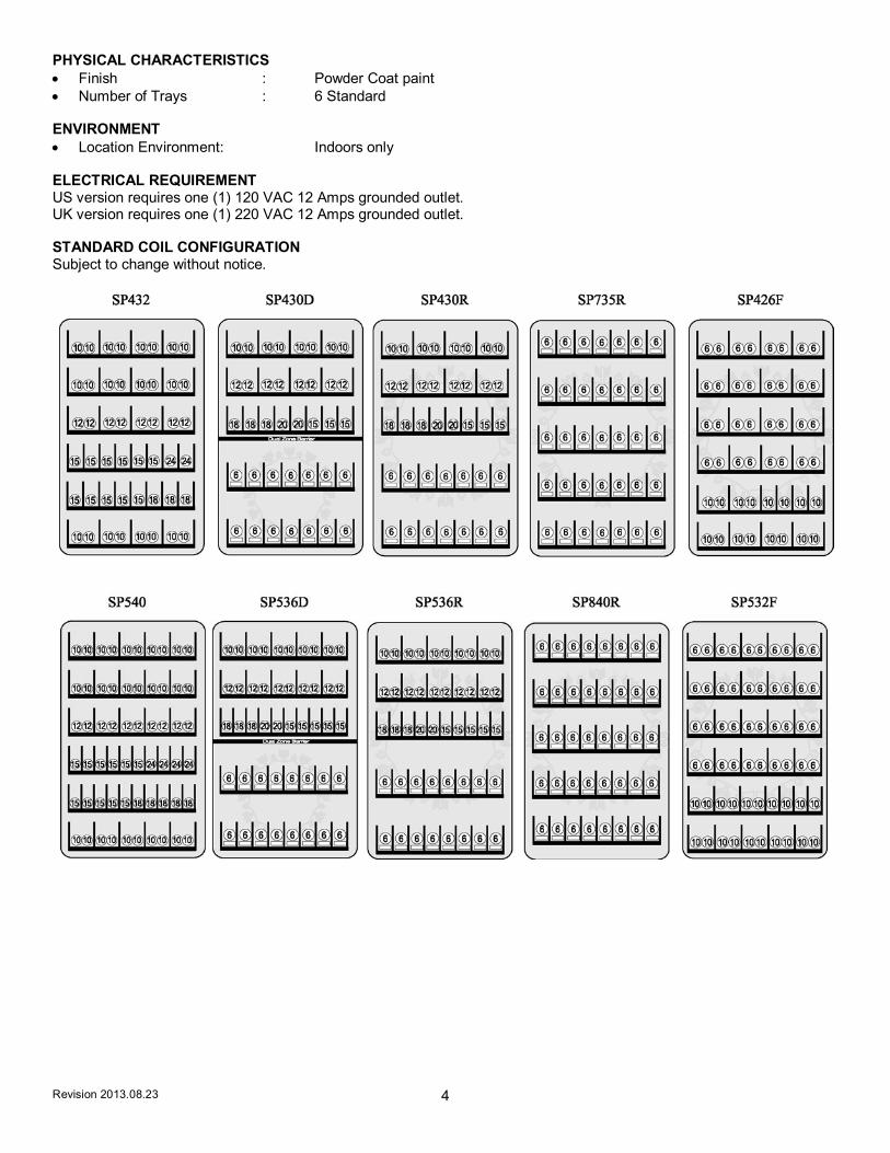
PHYSICAL CHARACTERISTICS Finish : Powder Coat paint Number of Trays : 6 Standard ENVIRONMENT Location Environment: Indoors only ELECTRICAL REQUIREMENT US version requires one (1) 120 VAC 12 Amps grounded outlet. UK version requires one (1) 220 VAC 12 Amps grounded outlet. STANDARD COIL CONFIGURATION Subject to change without notice.

Revision 2013.08.23 5
Fig. 1 - Exterior View (SP432 4-Wide Snack Machine Shown)
Protective shipping guards (Fig. 2) were installed on the leveling legs at the factory. Once the machine is placed near its final location the protective shipping guards may be removed. To remove the shipping guard, unscrew the leveling leg from the bottom until the guard is loose – a few turns only. The guard is held together with four phillips head screws and two brackets. Remove the screws and the guard will split in half for removal. Fig. 2 – Shipping Guards
Now place the machine into its final location. Using a level on the top of the machine, adjust the five leveling legs, if necessary, for proper level both side to side and front to back. A good point to keep in mind is the shorter the leveling legs are kept to achieve proper leveling, the more stable the machine will be.
Coin Slot
Lock
Display Window
Front Door
VFD Display
Key Pad
Bill Validator
Product Door
Coin Return Door
Coin Return Button
CAUTION: Certain procedures described in this manual require that voltage be on in the machine. Only trained personnel should perform these functions. Use extreme caution while performing the procedures marked with the voltage symbol shown here:
CAUTION: Certain procedures described in this manual require a qualified, trained technician to perform the particular task at hand. These procedures will be marked with the attention symbol shown here:
Screws
Screws
Leg Leveler
Protective Guard
Revision 2013.08.23 6
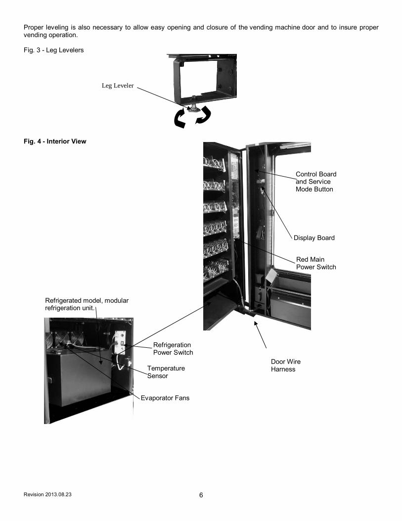
Proper leveling is also necessary to allow easy opening and closure of the vending machine door and to insure proper vending operation. Fig. 3 - Leg Levelers
Fig. 4 - Interior View
Control Board and Service Mode Button
Red Main Power Switch
Display Board
Door Wire Harness
Refrigerated model, modular refrigeration unit.
Evaporator Fans
Temperature Sensor
Refrigeration Power Switch
Leg Leveler

Revision 2013.08.23 7
SECTION 2 INSTALLATION
CAUTIONS
Your vendor is intended for indoor use only.Your vendor must be set on a level, well-supported location. Always unload vendor before transporting it. Remove all wire ties and protective sheeting prior to vending.
CAUTION! Procedures marked in this manual with the symbol shown to the left require power to the machine, which means that there is a shock hazard.
CAUTION! It is important that this machine is hooked up to the proper voltage. Verify the voltage before connecting the machine to a wall outlet.
CAUTION! Different countries may have different power arrangements. Insure that the machine is properly grounded before operating.
CAUTION! If the power cord is damaged, it must be replaced by the manufacturer, authorized service agent or a similarly qualified person to avoid electrical hazards.
ATTENTION! This vending machine is very heavy. Ensure that sufficient personnel are available for lifting or transporting the machine. Use proper lifting procedures and equipment.
CAUTION! Certain components of this machine are sensitive to static electricity. Precautions for handling sensitive devices should be observed when handling these items.
ATTENTION! Refrigerated models need air flow. Leave at least 6” between the back of the vending machine and the wall. Condenser cooling air is taken in the bottom and exhausted out the back of the machine. Clean the condenser once every two weeks or more often for high-particle locations.

Revision 2013.08.23 8
DOOR CLEARANCE
Please leave 7” clearance on the right side of the machine for the door to open and extend past the cabinet side. See clearance requirements above for refrigerated units. LOADING PRODUCTS To present your product in as an attractive and professional manner as possible, do not load any damaged items, and make sure items are facing forward for easy identification by your customer. Note: The size of the item being vended must be larger than the Helix Coil, but smaller than the Product Column to vend correctly. Never force an oversized item into the Helix Coil or Product Column, nor attempt to vend an item that is smaller than the Helix Coil as this will create problems and deter customers. (Fig.5) 1. To Load Product: A.) Use the release latches and pull the desired Product Tray all of the way forward. Product Tray will tilt down or can be removed and placed on the floor or a table.
Note: Pull out only one (1) Product Tray at a time. B.) Place product in proper size Helix Coil. Note: Bottom of product must
rest on the Product Tray and not on the Helix Coil. (Fig. 5) Load each Product Chute from front to back. Note: Do not leave any spaces between items.
C.) Once Product Tray is loaded, lift the front of the tray to level and push it back in. Repeat above steps until all Product Trays are fully loaded. D.) After loading the product, if you have removed the tray to do so, place the Tray in the cabinet by aligning the wheels in the guide rails. Clear the wire harness To the side so that it is not interfering with the tray below. To increase the length of the Helix Coil, white plastic Product Pushers can be snapped on the end. A supply of Product Pushers is provided in the hardware envelope. Note: We suggest that you always partially fill the vendor with product and perform at least five (5) test vends. Test vends can be performed easily by entering Service Mode and running "Individual Motor Testing". (See: Keypad and LED Display, Individual Motor Testing.) Fig. 5 – Loading Helix Coils
PRODUCT PUSHERS
Product pushers assist in moving the top of the product forward while it is being vended on the bottom, helping it fall smoothly from the shelf. Product pushers are also good for products that have the wrapper flaps on the ends of the package. Packaging such as this benefits from the extra momentum from the product pushers to keep the flaps from hanging up the product on the spiral. The pusher is installed approximately ½ inch from the end of the coil with the tab extending forward (see Fig. 6). Locate the pusher in its proper position, hold it against the coil wire and push the semi-circular part around the coil wire. Note: Boxed items will not need a product pusher.
Correct – load product between Helix Coils, resting on the product tray.
Helix Coil
Product Tray
Columns
Incorrect

Revision 2013.08.23 9
Figure 6 – Product Pusher Installation
LOADING BAGGED OR BOXED ITEMS
When vending small bagged items in the 8 or 10 selection trays can be a problem when the products are not loaded properly. The flap edges of some products may get trapped under the spiral and cause the product to “hang up”. It is recommended that the bottom flap of this type of packaging be folded forward and up (Fig. 5) next to the product when loading. This type of packaging also lets the product settle to the bottom, so using the wider spirals is also recommended.
LOCK
Your vendor has one Lock, more commonly known as T-handle lock. To unlock the front door, insert key and turn clockwise ¼ turn. When unlocked the ‘T’ of the Lock will pop out from its base. Turn the ‘T’ 15 to 20 times counter clock wise to unlock the door. To Lock the door turn the ‘T’ handle clockwise 15 to 20 times and then push the ‘T’ inside the Lock to lock the door. Key can now be removed. Note: Do not over-tighten when locking – this could strip the threads and damage your machine.
REFRIGERATION
If you purchased a refrigerated model, please see special information throughout the manual regarding refrigeration, settings and other information. The refrigeration system consists of Compressor, Relay circuit, Accumulator, condenser, condenser fan, evaporator, evaporator fans and air duct. The entire refrigeration system is modular and has a separate internal power cord, which is plugged in on the plug point provided at the bottom area below the last tray. The power switch has to be turned ON in order to start up the refrigeration system. There is a door switch that controls the refrigeration system ON and OFF condition. When the door is opened, the door switch is not depressed and the refrigeration system shuts OFF. When the door is closed, the switch is activated and the evaporator fans starts turning. There will be a delay before compressor starts running after the door closure. There is a vent on the cabinet back to blow the air from condenser. The inlet vent is at the bottom of the cabinet in front of the condenser. The condenser has to be cleaned regularly. The recommended frequency is once every two weeks. There are 2 clips around the front of the refrigeration module that has to be un-hooked in order to remove the front door of the refrigeration module. This will provide the access to the condenser. Using a vacuum cleaner or a brush, clean the lint in between the condenser fins. Note: Be careful not to bend the fins – this could restrict airflow and damage your machine. The compressor and the relay circuit, condenser fan motor and drain pan can be accessed in the same manner by removing the front door. The refrigeration system has to be unplugged and the module has to slide completely outside in order to gain access to these components.

Revision 2013.08.23 10
REFRIGERATION STATUS DISPLAY Use the “10” key on the Keypad to display the following indications of the refrigeration system on the VFD Display: Figure 7 – Refrigeration Indicators on VFD Display
SECTION 3 OPERATION
DISPLAY The VFD Display (Fig. 8) is a two line, 20 character text display panel located on the front of your vending machine. The display shows the customer the amount of money entered into the vendor and the cost of their selection among other information as programmed. It shows the operator the Service Mode functions for setting the various functions of the vendor. Fig. 8 – VFD Display
Delayed Start Mode – door switch is not being engaged; compressor will not start in this mode.
Cooling Mode – Door switch is engaged and compressor is active. The machine is cooling but not yet at operating temperature.
Defrost Mode – Machine is in defrost cycle. Defrost cycle time can be set using the Advance menu option Auto-Defrost in Diagnostics.
Zone 1: Zone 1 is active on the machine. Your SP series machine should only use Zone 2. Shut off Zone 1 in the diagnostics mode using the Advanced submenu.
If there are no indicators on the display, the machine is at the operating temperature.

Revision 2013.08.23 11
SERVICE MODE
Navigation of the Service Mode Menu
BUTTON FUNCTION
↑ Button This key is used to increase a numeric value, or move forward through the various service mode functions.
↓ Button This key is used to decrease a numeric value or move backwards through the various service mode functions.
F Button This key is used to confirm, accept, or ENTER into a service mode function.
G Button This key is used to EXIT the service mode or a service mode function.
Entering Service Mode To enter into service mode, open the vendor door and Press the Menus Service Mode Button (Fig. 10). After pressing the Service mode switch the controller will beep twice and the display will change to show “Service Menu” on the first line and “Prices” on the second line (Fig. 10). At this time you can use the keypad on the front of the machine to move through the various service mode MENUS.
F=ENTER
G=EXIT
↑= NEXT OR INCREASE
↓= PREVIOUS OR DECREASE

Revision 2013.08.23 12
Fig. 9 - Service Mode Button
Fig. 10 – VFD Display while in Service Mode. The Prices menu is the first sub-menu.
MENUS Service Mode Button

Revision 2013.08.23 13
Exiting service mode The controller will remain in service mode as long as the user keeps using the keypad to move through the various service mode MENUS. The controller will automatically exit service mode and return to sales mode if any of the following occur:
1) The user is inactive for more than 1 minute 2) The user presses the EXIT key (G).
After exiting the service mode, the installed firmware version shows on the display for three seconds, then the controller will revert to sales mode.
Service mode MENUS The chart below shows the sub-menus while in Service mode:
In the following instructions, refer to the drawing of the four button navigation key drawing on the left side of the page. Follow the arrows, paying attention to the navigation instructions (F), (G), (↑) and (↓)
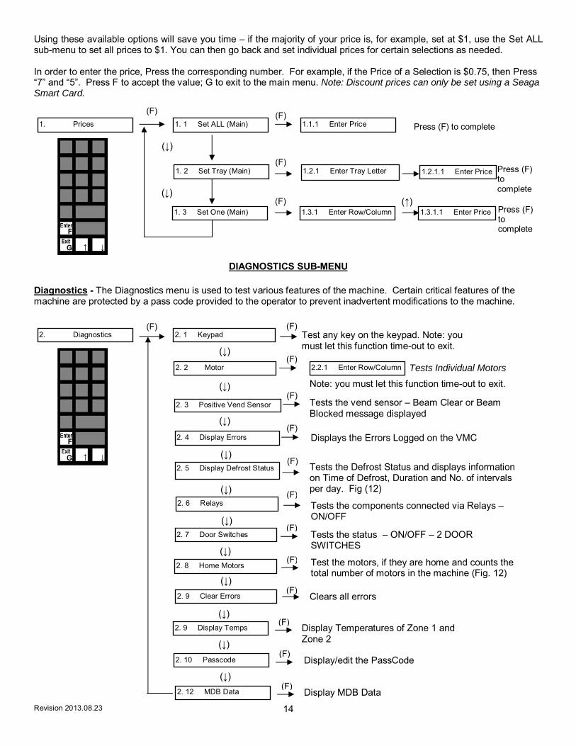
PRICES SUB-MENU
The Prices sub-menu allows you to set prices in three different ways – Set ALL, Set ONE, Set Tray. Set ALL will allow you to set all of selections in the machine to the same price. Set ONE will allow you to set one individual selection of your choosing. Set Tray will allow you to set an entire tray to the same price.
Revision 2013.08.23 14
Using these available options will save you time – if the majority of your price is, for example, set at $1, use the Set ALL sub-menu to set all prices to $1. You can then go back and set individual prices for certain selections as needed. In order to enter the price, Press the corresponding number. For example, if the Price of a Selection is $0.75, then Press “7” and “5”. Press F to accept the value; G to exit to the main menu. Note: Discount prices can only be set using a Seaga Smart Card.
DIAGNOSTICS SUB-MENU Diagnostics - The Diagnostics menu is used to test various features of the machine. Certain critical features of the machine are protected by a pass code provided to the operator to prevent inadvertent modifications to the machine.
1. Prices 1. 1 Set ALL (Main)
1. 3 Set One (Main)
1.1.1 Enter Price
1.3.1 Enter Row/Column 1.3.1.1 Enter Price
1. 2 Set Tray (Main) 1.2.1 Enter Tray Letter 1.2.1.1 Enter Price
2. Diagnostics 2. 1 Keypad
2. 2 Motor
2. 3 Positive Vend Sensor
2. 4 Display Errors
Test any key on the keypad. Note: you must let this function time-out to exit.
2.2.1 Enter Row/Column Tests Individual Motors
Tests the vend sensor – Beam Clear or Beam Blocked message displayed
2. 5 Display Defrost Status
2. 6 Relays
2. 7 Door Switches
2. 9 Clear Errors
2. 9 Display Temps
2. 10 Passcode
Tests the components connected via Relays – ON/OFF
Tests the status – ON/OFF – 2 DOOR SWITCHES
Clears all errors
Display Temperatures of Zone 1 and Zone 2
Display/edit the PassCode
2. 8 Home Motors Test the motors, if they are home and counts the total number of motors in the machine (Fig. 12)
Tests the Defrost Status and displays information on Time of Defrost, Duration and No. of intervals per day. Fig (12)
Displays the Errors Logged on the VMC
(F) (F)
(F)
(F)
(↓)
(↓) (↑)
Press (F) to complete
Press (F) to complete
Press (F) to complete
(F) (F)
(F)
(F)
(F)
(F)
(↓)
(↓)
(↓)
(↓)
(↓) (F)
(↓)
(↓)
(↓)
(F)
(F)
(F)
(F)
(F)
(↓)
(↓)
2. 12 MDB Data Display MDB Data (F)
(↓)
Note: you must let this function time-out to exit.

Revision 2013.08.23 15
AUDIT SUB-MENU
AUDIT MENUS -The Audit Menu is used to track the machine operation in all aspects but not limited to the transactions.
3. Audit 3. 1 Coins In
3. 2 Change Out
3. 3 Bills In
3. 4 Card In
3.8.1 Enter Row/Column
3. 6 Free vends
3. 7 Sales value
3. 8 Selection
Displays Total Amount of Coins inserted during transactions
3. 5 Manual Dispense
Displays Total Amount of Coins dispensed during transactions
Displays total Amount that is dispensed manually during servicing of Coin Mechanism
Displays Total Number of Free Vends
Displays Total Sales Cash Value
Displays Total no. of vends on that individual selection
Displays Total Amount of Bills inserted during transactions
Displays Total Amount of Card Transaction
Fig. 11 Fig. 12
(F)
(↓)
(F)
(F)
(F)
(F)
(F)
(F)
(F)
(F)
(↓)
(↓)
(↓)
(↓)
(↓)
(↓)
3. 9 Total Sales Count Displays Total sales for this machine. This number is cumulative – a running total.
(F) (↓)

Revision 2013.08.23 16
SETTINGS SUB-MENU SETTINGS - This menu is used to Setup the features of the machine.
4. Settings 4. 1 Clock
4. 3 Lockout expiry
4.1.2 Date
Set Day of the week – 1 – Sunday 2 – Monday 3 – Tuesday 4 – Wednesday 5 – Thursday 6 – Friday 7 - Saturday
Set Time and Date for the Lockout settings to expire
4. 4 Temperature Limits
4. 5 Timed Lockout
4. 6 Coin Refill
4. 7 Multivend
4. 8 Forced Vend
Enables you to set two lock-out time durations per day. Ensure your date and time settings are correct prior to using this function.
4.9.1 Coin Changegiver
4.1.3 Day of Week
4.1.1 Time
Set Date on the machine
Set Time on the machine
4.4.1 Zone 1 Upper
4.4.2 Zone 1 Lower
4.4.3 Zone 2 Upper
4.4.4 Zone 2 Lower Setup the Lower limit for Zone 2
Setup the Lower limitfor Zone 1
Setup the Upper Limit for Zone 2
Setup the Upper Limit for Zone 1
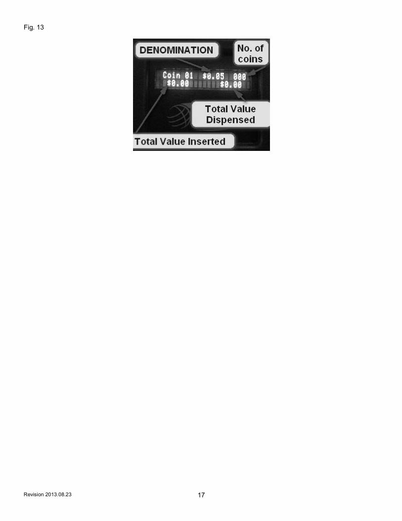
Shows the count of the coins of each denomination being inserted. Manual Dispense of the Coin mech is enabled in this menu option (Fig. 13). Depending on the model of changer installed, the amount will vary.
4. 9 Payment Devices
4.9.2 Bill Reader
4.9.3 Card Reader #1
4.9.4 Card Reader #2
4.9.5 Executive
Enabled/Disabled
ON/OFF
ON/OFF
4.2 Tokens/Coupons ON/OFF
Enabled/Disabled
Enabled/Disabled
Enabled/Disabled
Enabled/Disabled
4.10 Satellite Machines
(F)
(↓)
(F) (F)
(↓)
(↓)
(↓)
(↓)
(↓)
(↓)
(↓)
(↓)
(↓)
(↓)
(F)
(F)
(F)
(F)
(F) (F)
(F)
(F)
(F)
(F)
(F)
(F)
(F)
(F) (F)
(F)
(F)
(F)
(F)
Revision 2013.08.23 17
Fig. 13

Revision 2013.08.23 18
ADVANCED SUB-MENU ADVANCED - This menu is used to setup the Advanced Settings. Please enter the Pass Code in order to access this menu.
5. Advanced 1 5. 1 Coins/Bills
5. 2 Manual Lockout
5.1.2 Bills
Set the machine to Lock Out (Use the Clear Errors function to remove Lock Out status )
5. 3 Language
5.1.1 Coins Coins ON/OFF
Bills ON/OFF
Select the Language
5.13 Passcode
5.4 Health Safety ON/OFF
5.5 Temp Zone 1
5.6 Temp Zone 2
5.7 Rows / Columns
5.7.1 Use to toggle through Tray A – Tray H Press #1 repeatedly to change number of columns Press #2 changes from Vend Sensor to Home Switch F changes Vend Sensor On or Off This should only be changed under advisement of a trained service provider or Seaga customer care.
5.9 Formats
5.11 Asset Number
5.10 Machine number
5.12 Default Types Select from list of standard set-ups and action
5.13.1 Display/edit
ON/OFF
ON/OFF
5.9.1 Date Format – US style mm/dd/yy or European Style dd/mm/yy
5.9.2 Temp Format in Degrees Fahrenheit or Celsius
Insert Number and Press F to confirm
Insert Number and Press F to confirm
(F) (F)
(F)
(F)
(F)
(F)
(F)
(F)
(F)
(F)
(F)
(F)
(F)
5.8 Auto Defrost
ON/OFF
(F)5.8.1 ON/OFF Use number keys to enter Duration and Intervals per day. This should only be changed under advisement of a trained service provider or Seaga customer care.
5.14 MDB Card Coding 5.14.1 Transfer MDB information to Smartcard(F)

Revision 2013.08.23 19
EXIT SERVICE MODE To Exit the Service Mode or any of the menus, press “G”. SECTION 4 SMARTWARE V2.1.0
The Seaga Smartware setup utility enables Setup smart cards to be used to set the configuration of the new generation of Seaga vending machine controller boards. The utility works in conjunction with a USB smart card reader. System Requirements
Seaga Smartware CD
Approved USB Card Reader
Seaga Smart Cards
PC with the following specification: Minimum Recommended Processor Pentium 200MHz Processor Pentium P4 1000MHz or
better RAM 128M byte > 256M byte RAM Free Hard Disc Space 20Mbyte > 100Mbyte Graphics 800x600 16 colour SVGA 1024 x 768 256 colour SVGA Operating System Windows 98SE Windows Me, 2000, XP or
Vista CD-ROM Yes Yes USB port One More than One Software Installation (i) Installation of Card Reader Drivers Either :
Insert the CD into the CD ROM drive Select the “Install Card Reader Driver” option
Or (Windows XP / Vista only):
Insert the CD into the CD ROM drive Plugg the card reader into the PC and follow the instructions in the “Add New Hardware”
wizard. The Card Reader drivers are located in the /drivers/ folder on the CD. Or :
Run the programme "setup.exe" in the " /2/ " folder on the CD and follow the instructions. (ii) Installing the Smartware Application Either:
Insert the CD into the CD ROM drive Select the “Install Seaga Smartware” option
Or:
Run the program "setup.exe" in the top level folder on the CD and follow the instructions

Revision 2013.08.23 20
CONFIGURATION PAGE
General Operations
Read Seaga Smart Card – read an existing smart card Write Seaga Smart Card – programme a card with the current settings Save to File – save the complete settings to a text file Load from File – restore previously saved configurations Check Website for Latest Version – Hyperlink to www.seagamfg.com/smartware/index.html Display User Guide
– Hyperlink to www.seagamfg.com/smartware/Seaga Smartware Guide.pdf Exit – close the utility programme Card Status – shows the status of the card reader
No card inserted (Read and Write Card buttons disabled) Seaga 256K smart card Standard smart card inserted Seaga 512K smart card Alternate smart card inserted
Notes If an Audit or a Temperature Logging Card card type being read the data will be saved to a file once the read is complete. There is a prompt for the file name and an option to clear the card after it has been saved to the file. Refer to Appendix 1 for the file formats.

Revision 2013.08.23 21
CONFIGURATION PAGE (continued)
Machine Selection / Basic Settings
Use the Machine Type “pull-down” to select a standard machine configuration, or select a specific VMC type.
Multivend, Forced Vend, Accept Tokens/Coupons and Sound ON – check the option to enable the corresponding feature. Lottery Mode – check this option and enter a “Vend Count” value to allow a free selection, every “Vend Count” vends.
Satellite Machine n - check the box to allow the VMC to work with the corresponding Satellite machine.
When a Satellite machine type (VMC type EL906) is selected there is an option to configure the machine as Satellite 1, Satellite 2 or Satellite 3.
Note : some features described in this guide are not available on all VMC configurations. If a particular item is “greyed out” or not shown, it is not available for the current machine.

Revision 2013.08.23 22
PRICES PAGE
Depending on the machine configuration, up to 80 Price Boxes will be displayed for the machine. To set a particular price type the value, in cents/pence, into the corresponding price box. To set ALL the prices to the same amount, enter the amount in the ALL Price box and click the Set All Prices button. The VMC can hold prices for the Main Machine and also up to three Satellite (MDB USD) machines – prices for the satellite machines can be accessed using the Machine “pull down” menu. Individual selections may be named – refer to the Text Messages page for more details

Revision 2013.08.23 23
PRICES PAGE (continued)
Discount Prices Select Discount Prices using the Price Bank pull-down. The VMC can operate at discounted prices between the Discount Start Time and Discount End Time points - refer to the “Timed Events” section.

Revision 2013.08.23 24
PRICES PAGE (continued)
Meal Deals These are multiple selections that may be offered at a discount price for the group of selections. Meal deals are selected using the special selection prefix “GG” followed by the 1 – 10 key. The Meal Deal price is charged to the customer and multiple products are vended as specified. Each of the 10 meal deals can have an individual price, followed by a list of selections that make up the deal. Each deal can comprise up to 4 selections which may be from the Main machine, or from Satellite machines. In the example above meal deal GG2 comprised selection D1 from the main machine plus selection A10 from the second satellite machine.

Revision 2013.08.23 25
INTERNATIONAL PAGE
Language
Select the default language for the display using the pull-down list. One language option is EEPROM. This language bank may be edited for special configurations and non-supported languages. Refer to the Text Messages page for more details.
Currency Display
Choose the desired currency Symbol and the number of Decimal Places to be displayed. If the required currency symbol is not in the options, choose Custom and type in two characters in the Custom Symbol box.
Date Style
Choose between mm/dd/yy and dd/mm/yy styles Temperature
Choose between displaying Centigrade and Fahrenheit. IMPORTANT: Check the values on the Refrigeration Page AFTER changing the Temperature scale.
Clock
Choose between 24 hour and 12 hour modes to be displayed. Select the Daylight Saving Time option for automatic summer/winter changes in the USA and the UK/Europe if required.

Revision 2013.08.23 26
PAYMENT PAGE
Payment Devices
Check the corresponding boxes to turn Card, Coin and Bill payment on
Executive – check this box to operate with an Executive / Protocol-A coin changegiver. Coin Changegiver
Check the Enabled box to allow the corresponding coin to be accepted normally, and the Enabled in Exact Change box to allow this coin to still be accepted when the machine is in Exact Change mode. Check the Manual Dispense ON box to allow tubes to be emptied manually.
Bill Reader
Check the Enabled box to allow the corresponding Bill to be accepted. Check the Use Escrow box to hold the Bill for change and the High Security box to use the corresponding bill acceptance security level.
Exact Change Algorithm
The VMC applies two criteria for creating the Exact Change condition. Exact Change is set when ANY tube has less coins in the tube than the Minimum Coins In Tube quantity OR if the total value of the coins in the tubes is less than the highest price set multiplied by the Minimum Value in Tube multiplier.
Special Features Card Reader can Change Price – check this box to allow the card reader device to apply discounts.

Revision 2013.08.23 27
SPACE to SALES PAGE
Stock Links
Where more than one selection contains the same product it is possible to link these selections together so that if one selection is sold out the product can be dispensed from another selection. This is particularly useful for increasing the effective stock for Meal Deals, and for Can/Bottles operation.
In the example above selections D1, D2 and D3 have the same type of product and have been linked together in a chain. All other selections are not linked and refer back to themselves.

Revision 2013.08.23 28
HOT BUTTONS (Space to Sales Page)
Hot Buttons
Check the “Active Button” to use Hot Buttons. Hot Buttons replace the standard keypad selections with up to 5 direct, single button selections. For capacity the Space To sales links allow multiple internal spirals to stock the same product. In the above example Hot Button 1 selects effectively Tray A. The hot button is linked to Selection A2 which in turn is linked in a chain to the other selections in Tray A. Similarly hot buttons 2 – 5 access trays B to E respectively.

Revision 2013.08.23 29
TEXT MESSAGES PAGE
VMC Text Messages This window displays the text held in EEPROM for an alternate language set. To Edit the VMC Text Messages use the Save to File button to save the text to a particular file . This file can be edited using Notepad and then reloaded using the Load from File button. Selection Names This window displays the text that is displayed for each Selection or Meal Deal. To Edit the Selection Names use the Save to File button to save the text to a particular file . This file can be edited using Notepad and then reloaded using the Load from File button. When either of the “Save to File” options are selected Windows Notepad is launched directly to allow easy editing. IMPORTANT: When editing is complete save the changes from within Notepad and then use the Load from File button to install the changes.

Revision 2013.08.23 30
ADVANCED PAGE
Build Configuration
This section allows the tray options to be defined for the particular machine. Select the number of columns for a particular tray, the Motor Type as below, the overall run Timeout in seconds for the motor and whether a Sold Out switch is fitted. Motor Types : Cycle Switch - stops when the Home Switch is reached PV Sensor - stops when a product triggers the “Positive Vend Sensor” Timed - runs for a fixed period of time Positive Vend Sensor - check this box if one is fitted and to be used for the corresponding tray. (Please
note that some older VMC software versions may not support individual use of the Positive Vend Sensor)
Timings
Selection Timeout is the number of seconds for which a selection is deemed made, and for which the product name and price are displayed. Motor Nudge Time is the amount of time the motor is run after it has “homed” when the Positive Vend Sensor has not been triggered
Configuration
Motor Nudges - define the maximum number of nudges (up to 6) to be used Diagnostics Passcode - a 4 digit code for access to additional diagnostic features in the menus. Advanced Passcode - a 4 digit code for access to the Advanced menu features.
Make Logging Smart Card / Make Audit Smart Card
– create a blank smart card of the selected type.

Revision 2013.08.23 31
REFRIGERATION PAGE
Zone n ON – check the appropriate boxes turn refrigeration control ON for the Zone Low Limit / High Limit Temperatures – set the upper and lower temperature limits for the zone. Note: the VMC internally works in 0.5C steps so exact Fahrenheit figures may be adjusted to the nearest 0.5C step. Auto Defrost Check the box to turn automatic defrosting ON. The defrost cycle is run for Defrost Duration minutes every Interval hours. The First Defrost after turning the feature ON may be set with the pull-down option. Thereafter the Interval value defines when the next defrost will occur. Health & Safety Mode ON – check the box to turn this lockout mode ON.

Revision 2013.08.23 32
TIMED EVENTS PAGE
Version 1.10 and later Premier VMC software supports up to 32 separate timed events. Each event can be set to occur between the START and END times for the selected days of the week. Event times may overlap. Each Event can then have the following actions (more than one selection may be applied)
LO Timed Lockout En Refrigeration Energy Saving Mode Li Lights OFF FV Free Vend DV Discounted Vend (If both DV and FV are selected, free vend will apply)
Use the Defaults button to clear the events back to the factory default configuration Events 1 – 4 are backwards compatible with earlier versions of VMC software.
Events 1 and 2 Timed Lockouts with shared Days of the Week active. Event 3 Energy Saving only Event 4 Discounted Vend only
In the screenshot above the following events are set for an example “factory/office” application:
Discounted prices for anyone working late 17:00 to 20:00 on weekdays
Free vend for anyone working after 20:00 on weekdays and between 08:00 and 18:00 at weekends.
Energy saving every night from 22:00 until 06:00 the next morning, which means that In Energy saving Mode, the compressor will shut off at 40 °F and turn on when the temperature reaches 43° F. (During normal operation the temperature range is held from 37 °F to 43 °F.
Timed Lockout between 10:00 and 10:15 on Tuesdays, Wednesdays and Thursdays for a “staff meeting”

Revision 2013.08.23 33
Appendix 1 – File formats Both Audit and Temperature Logging Cards are saved to .csv (comma separated value) format files that can be imported into a number of packages, including Microsoft Excel. Records are tabulated with a title to each column. Example Audit File – values are in base units (cents, pence etc.) Example Temperature Logging File – in this example, temperatures are in Centigrade, defrost duration is in minutes. Readings are logged approximately every minute.

Revision 2013.08.23 34
SECTION 5 DELIVERY OF PRODUCT
DELIVERY SYSTEM
Your vendor consists of the Keypad, 2 Line VF Display, Driver Motors, Product Trays, Helix Coils and Delivery Bin. The customer inserts money and enters their selection on the Keypad. The selection's Driver Motor turns the Helix Coil that vends the product into the Delivery Bin.
PRODUCT TRAYS The SP Series features lock and release product trays. On the right side of each product tray you will find a Locking Lever (Fig. 14). To pull out the Product Tray push down on the Locking Lever and roll toward you to tilt position. Or completely push the locking lever to the back. Fig. 14
VIGILANT VEND SENSOR SYSTEM
The Vigilant system is a series of infrared sensors that send a beam of light across the delivery bin. If this beam is broken by a product, the Premium machine knows that an item was delivered to the customer. If this beam is not broken, the Premium machine assumes that nothing was vended and turns the selection spirals by ¼ turns until a product delivery is sensed. If, after the coils have turned a full revolution back to home without delivering a product, the customer will be asked to make another selection or to press the Coin Return button to receive their money back. Certain products can be problematic for any vend sensing system. Products that are very thin or very small in size may, on occasion, miss the beams. With proper loading of the machine, sensing systems are irrelevant. A comfort level is provided to customers who walk up to the machine and know, through technology, they will not experience a “rip-off”. For this reason, a vend sensor system is desirable – however, if you vend very small or very thin items, you may want to consider turning off your sensing system in case of malfunction via product size. See the Service Mode section of this manual, Diagnostics sub-menu, for instructions. The Vigilant sensors are located inside the delivery bin as shown in Figure 14 below. There is a red indicator light located on the left side when viewing the bin from the inside with the door open. This light should be lit when the system is on, indicating that there is power to the system. Blocking any of the beams turns off the red indicator light, which means the system is working correctly. Note: When performing Test Motors without product loaded, it is a good idea to shut off the Vigilant system. SECTION 6 TROUBLE SHOOTING 1.
a. Transformer fuse blown b. Display board defective c. System control board defective d. Faulty display harness e. Harness may be unplugged f. Restart machine
NO DISPLAY ON THE FRONT PANEL
White Locking Lever

Revision 2013.08.23 35
2.
a. Vend mechanism binding on tray b. Product jammed c. Tray or Motor connection unplugged or faulty connection d. Bad motor or defective motor e. System control board defective f. Detection system may be blocked, if enabled
3.
a. System control board defective b. Defective motor switch c. Detection system malfunction, if enabled
4.
a. Defective motor b. Motor harness not plugged into the vend motor correctly c. Defective or damaged motor interface board [KS11] d. Tray cable faulty e. System control board defective
5.
a. All Prices are set to zero or machine is set to Free Vend b. Will not accept bill if coins in coin changer below the minimum level c. Will not accept more than one bill if the bill equal or exceeds the highest priced item. d. No power to system control board e. Coin Mechanism or Bill acceptor defective.
A: These buttons are disabled in the normal operating mode to protect from unauthorized use. To enable the buttons enter the service mode, scroll to the settings submenu, press F to enter then scroll to Coin Refill and press F. The button will now be enabled. To exit press the G button multiple times. Q: I rearranged my trays and now some selections don’t work. Display says Make Alternate Selection. A: Enter the service mode. Press the 10 button 4 times. Display should show Passcode Accepted. Scroll to Advanced sub menu and press F to enter. Scroll to Rows / columns setting and press F to enter. Display will show setting for each tray position. The 1 button will cycle through the different tray configurations. It will cycle from 0 (tray off) then to 4, 5, 7, 8, 10 then back to 0. Set this to the number of selections on that tray. When finished with the settings for that tray use the arrow keys to scroll to the next one to set. If you are finished press the G key multiple times to exit. This only applies to machines with software revision .65 and higher. Earlier versions will require a software update. Contact your distributor or sales person for update information. Q: My machine will not take in bills but accepts change ok. A: Several options here but the most common especially when first setting up the machine is that there is not enough change in the changer. By looking at the display it will give you a clue as to what may be wrong. If the display reads “Please Insert Exact Money….” that indicates there is not enough change in the changer. Fill the coin tubes
SELECTION WILL NOT VEND
MULTIPLE VENDS FROM ONE SELCTION
MULTIPLE VENDS MORE THAN ONE SELECTION SIMULTANEOUSLY
UNIT WILL NOT ACCEPT MONEY

Revision 2013.08.23 36
completely full. Completely full means you can’t get any more change into the coin tube. Press the coin return button and the display should show Canceling. The display should now show “Please Insert Money…..” without the word Exact. Q: My machine still will not accept bills and the display does not indicate Exact change. A: If the validator takes in the bill a ways but spits it back out, that indicates that the bill may be unacceptable or the validator needs cleaning. Follow the validator manufacturer’s recommendation for cleaning. Q: My machine will accept $1 bills ok but not $5 bills. A: This situation can depend on several factors. The amount of change being reported in the changer and the highest vending price in the machine. Make sure the changer is full of change. If you are vending high dollar items you may need to replace the changer with a larger capacity model and/or one that utilizes dollar coins if the changer is constantly low on change. Q: My machine will not accept the new $5 bills. A: Contact the bill validator manufacturer for upgrade instructions. Not accepting currency that has been changed due to a Federal Government mandate is not covered under our manufacturer’s warranty. Q: My machine will vend a product, display Vend Error then give my money back or allow me take make an alternate selection. A: This indicates there is a problem detected with the vend motor. Each vend motor has a small micro switch inside that indicates when the motor has made one full revolution and returns back to what is referred to as the “home position”. If this signal is not received back to the controller in a specified amount of time the controller will indicate and error and refund the money. The problem could be in an individual motor itself, the tray wire harness or any connection in between the tray to the control board. If the whole tray acts this way that usually indicates that the tray harness or any connection in between to the controller may be bad. The easiest way to troubleshoot this situation would be to swap tray connections where the tray harness plug plugs into the machine. For example it the problem appears on the A tray, unplug the A tray and the B tray (assuming they both have the same number of selections), swap the connections and plug the A tray into the B tray receptacle and vice versa. Now do your test vending by selecting the B selections on the keypad and the A tray should operate. If the problem follows the tray then suspect either the motor or the tray cable harness. If the problem stays with the A receptacle and now the B tray exhibits the problem then the problem is in a connection somewhere between the A receptacle and the controller board. Make sure to examine any and all connections for any loose wires, etc. Q: My display is dead or intermittent but the rest of the machine appears to be working. A: Check the gray flat ribbon cable connection between the display and the controller board to insure the plugs are plugged in securely. Q: My machine will not cool. A: Several things to check here.
1. Make sure the machine programming is set up properly so that Zone 2 is enabled and the proper temperature limits are set for Zone 2. Zone 2 lower should be set around 37 degrees and Zone 2 upper should be around 5-6 degrees warmer. If the temperature is set too cold then you risk the chance of evaporator freeze over.
2. On models equipped with a refrigeration fuse make sure it is not blown. The fuse needs to be a 20 amp Slo-Blo fuse. Nothing less. An easy way to test the fuse is to press on the lower door switch to see if the 3 evaporator fans run that are located below the bottom tray.
3. Inspect the evaporator coil to see if it may be frozen over. Using a flashlight shine it into the 3 evaporator fans located under the bottom tray. You are looking for aluminum fins behind the fan motors. If they are completely white or solid with ice this will keep the air from flowing properly and cause the machine to not cool. To thaw out remove the 3 prong condensing unit plug, not the evaporator fan plug and just close the door and let set for overnight to insure it completely defrosts. Be prepared in case the defrost water pan overflows on the floor. You may need to set some towels around and under the machine to catch any overflow. After the machine is thawed completely out you will want to check the temperature settings to insure they are not set too cold. You may also enter the Advanced menu and check the defrost settings. The standard defrost settings are for a duration (DUR) of 25 minutes and interval (INT) of 3 hours. This can be changed if need be. Press the lower door switch to insure all 3 evaporator fans run. Also close the door and listen to hear if the fans start when

Revision 2013.08.23 37
you close the door. If they don’t this will also cause a freeze over. You may need to adjust the door switch to facilitate proper operation.
4. Check the upper door switch. The easiest test is to close the door then while opening the door watch the display to see if you see the message Sales Value $xxxx.xx in the display. If you do not then suspect the upper door switch may need adjustment. You can reach over the door and press it manually while watching the display to see if it works.
5. As a manual test of the cooling system you can enter the Diagnostics section of the menu and select the Relays test function. Select Relay 02, press F and the cooling system should turn on momentarily.
6. Another manual test you can try on models equipped with a standard 3 prong receptacle for the cooling assembly is unplug the cooling assembly plug from the refrigeration control panel and plug that cord into a standard 3 prong extension cord. The cooling system should run.
CAUTIONS:1. High voltage is located in the area of the unit and could cause injury or death. 2. Replacement of the bill acceptor, coin changer, front panel display, system control board or
vend motors should only be performed by trained personnel.
Revision 2013.08.23 38
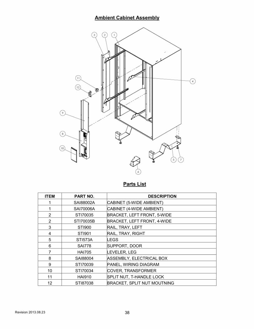
Ambient Cabinet Assembly
Parts List
ITEM PART NO. DESCRIPTION
1 SAI88002A CABINET (5-WIDE AMBIENT)
1 SAI70006A CABINET (4-WIDE AMBIENT)
2 STI70035 BRACKET, LEFT FRONT, 5-WIDE
2 STI70035B BRACKET, LEFT FRONT, 4-WIDE
3 STI900 RAIL, TRAY, LEFT
4 STI901 RAIL, TRAY, RIGHT
5 STI573A LEGS
6 SAI778 SUPPORT, DOOR
7 HAI705 LEVELER, LEG
8 SAI88004 ASSEMBLY, ELECTRICAL BOX
9 STI70039 PANEL, WIRING DIAGRAM
10 STI70034 COVER, TRANSFORMER
11 HAI910 SPLIT NUT, T-HANDLE LOCK
12 STI87038 BRACKET, SPLIT NUT MOUTNING

Revision 2013.08.23 39
Refrigerated Cabinet Assembly
Parts List
ITEM PART NO. DESCRIPTION
1 SAI87001 CABINET, INSULATED (5-WIDE REFRIGERATED)
1 SAI84007 CABINET, INSULATED (4-WIDE REFRIGERATED)
2 SAI793 ASSEMBLY, ELECTRICAL PANEL
3 SAI764A ASSEMBLY, DOOR SUPPORT ROLLER
4 STI573A LEGS
5 HAI705 LEVELER, LEG
6 SAI781A SUPPORT, DOOR
7 STI58022 GRILL
8 STI579 RAIL, BEVERAGE TRAY, LEFT/RIGHT
9 STI900 RAIL, SNACK TRAY, LEFT
10 STI901 RAIL, SNACK TRAY, RIGHT

Revision 2013.08.23 40
Ambient Door Assembly
ITEM PART NO. DESCRIPTION 1 SAI88012B ASSEMBLY, DOOR (5-WIDE AMBIENT) 1 SAI70003A ASSEMBLY, DOOR (4-WIDE AMBIENT) 2 HAI909 T-HANDLE 3 PLI940 FRAME, DELIVERY DOOR 4 PLI939 BEZEL, COIN RETURN 5 SAI780 ASSEMBLY, HINGE, BOTTOM 6 SAI87033 ASSEMBLY, GUIDE COIN BOX 7 SA87038 TRAY, COIN RETURN 8 SAI87035 ASSEMBLY, COIN BOX 9 SAI809 ASSEMBLY, DELIVERY BIN (5-WIDE AMBIENT) 9 SAI810 ASSEMBLY, DELIVERY BIN (4-WIDE AMBIENT)
10 SAI777 ASSEMBLY, HINGE, TOP 11 PLI2082 CAP, TUBE, LED 12 HAI990A TUBE, LED 13 ELI962 LED 14 HAI990 TUBE, LED 15 STI87025A COVER, DOOR LOCK 16 PLI936 BEZEL, KEYPAD 17 SAI773A ASSEMBLY, COIN RELEASE 18 GLI953A GLASS (5-WIDE AMBIENT) 18 GLI962 GLASS (4-WIDE AMBIENT) 19 STI70062 PLATE, DISPLAY MOUNTING 20 ELI909 DISPLAY

Revision 2013.08.23 41
Refrigerated Door Assembly
ITEM PART NO. DESCRIPTION
1 SAI87009 ASSEMBLY, DOOR, INSULATED (5-WIDE) 1 SAI84009 ASSEMBLY, DOOR, INSULATED (4-WIDE) 2 HAI909 T-HANDLE 3 PLI936 BEZEL, KEYPAD 4 PLI939 BEZEL, COIN RETURN 5 SAI780 ASSEMBLY, HINGE, BOTTOM 6 SAI87033 BRACKET, COIN BOX 7 SAI87038 TRAY, COIN RETURN 8 SAI87035 ASSEMBLY, COIN BOX 9 SAI87031 ASSEMBLY, ELECTRICAL DOOR, REFRIGERATED
10 SAI773A ASSEMBLY, COIN RELEASE 11 ELI900 VMC 12 PLI943A DELIVERY DOOR (5-WIDE) 12 PLI943 DELIVERY DOOR (4-WIDE) 13 STI87049 PANEL, ANTI-THEFT (5-WIDE) 13 STI58036 PANEL, ANTI-THEFT, BIN (4-WIDE) 14 PLI940 DELIVERY DOOR 15 SAI785 ASSEMBLY, DELIVERY BIN (5-WIDE REFRIGERATED)15 SAI360 ASSEMBLY, DELIVERY BIN (4-WIDE REFRIGERATED)16 GLI954A GLASS, INSULATED (5-WIDE) 16 GLI952A GLASS, INSULATED (4-WIDE) 17 STI70061 PLATE, DISPLAY MOUNTING 18 ELI909 DISPLAY 19 SAI777 ASSEMBLY, HINGE, TOP 20 PLI2082 CAP, TUBE, LED 21 HAI990A TUBE, LED 22 ELI962 LED 23 HAI990 TUBE, LED 24 STI87025A COVER, DOOR LOCK 5-WIDE 24 STI87025B COVER, DOOR LOCK 4-WIDE 25 STI70033 BRACKET, DEX SUPPORT

Revision 2013.08.23 42
Refrigeration Deck Assembly
Parts List
ITEM PART NO. DESCRIPTION
1 STI87029 TRAY, REFRIGERATION DECK
2 SAI87011 DECK HOUSING
3 SAI87051 ASSEMBLY, EVAPORATOR HOUSING
4 REI819 CONDENSER
5 REI830 EVAPORATOR
6 SAI87013 DOOR REFRIGERATION DECK
7 SAI87013 TRAY EVAPORATOR
8 STI87030 TRAY, CONDENSATE
9 STI578 BRACKET, CONDENSER MOTOR
10 STI87019 BRACKET, LATCH CLAMP
11 REI872 COMPRESSOR
12 REI612 MOTOR, CONDENSOR
13 REI861 BLADE, CONDENSOR
14 STI8703T6 L-ANGLE, REF. DECK HOUSING
15 STI87037 SHROUD, CONDENSER
16 STI87038 BRACKET, CONDENSER

Revision 2013.08.23 43
Ambient Delivery Bin Assembly
Parts List
ITEM PART NO. DESCRIPTION
1 SAI70009A DELIVERY BIN ASSEMBLY (5-WIDE)
1 SAI70021A DELIVERY BIN ASSEMBLY (4-WIDE)
2 SAI775 VEND SENSOR ASSEMBLY, RIGHT
3 SAI779 VEND SENSOR ASSEMBLY, LEFT
4 STI87055 ANTI-THEFT BRACKET (5-WIDE)
4 STI58034 ANTI-THEFT BRACKET (4-WIDE)
5 STI87049 PANEL, DELIVERY BIN (5-WIDE)
5 STI58036 PANEL, DELIVERY BIN (4-WIDE)
6 PLI943A DELIVERY DOOR (5-WIDE)
6 PLI943 DELIVERY DOOR (4-WIDE)

Revision 2013.08.23 44
Refrigerated Delivery Bin Assembly
Parts List
ITEM PART NO. DESCRIPTION
1 SAI87016 DELIVERY BIN ASSEMBLY (5-WIDE)
1 SAI58010 DELIVERY BIN ASSEMBLY (4-WIDE)
2 STI87055 ANTI-THEFT BRACKET (5-WIDE)
2 STI58034 ANTI-THEFT BRACKET (4-WIDE)
3 SAI775 VEND SENSOR ASSEMBLY, RIGHT
4 SAI779 VEND SENSOR ASSEMBLY, LEFT

Revision 2013.08.23 45
Electrical Panel Assembly
Parts List
ITEM PART NO. DESCRIPTION
1 STI87017 ELECTRIC PANEL
2 ELI504A TRANSFORMER
3 ELI946 FILTER
4 ELI764 RELAY
5 STI84018 SWITCH BRACKET
6 ELI922 AUXILARY BOARD
7 STI84019 POWER BOX
8 STI84020 ELECTRICAL BOX FRONT PLATE
9 ELI916 ON/OFF SWITCH
10 ELI972 CIRCUIT BREAKER

Revision 2013.08.23 46
Vigilant Vend Sensor, Right Side Assembly
Parts List
ITEM PART NO. DESCRIPTION
1 STI70086 SENSOR BRACKET
2 PLI609A SPACER
3 ELI974 EMITTER
4 FAI922 NUT
Vigilant Vend Sensor, Left Side Assembly
Parts List
ITEM PART NO. DESCRIPTION
1 STI70086 SENSOR BRACKET
2 PLI609A SPACER
3 ELI2169 DETECTOR
4 FAI922 NUT

Revision 2013.08.23 47
8 SpaceTray Assembly, Confectionery (Candy)
ITEM PART NO. DESCRIPTION
1 SAI84024 ASSEMBLY, WELDED TRAY
2 FAI923 NUT, NYLOCK, M6
3 PLI802A WHEEL, TRAY
4 HAI602 PIN, WHEEL, TRAY
5 PLC958 PROFILE, PRICE SELECTION
6 HAI976 PIN, PROFILE LABEL HOLDING
7 STI70010A PARTITION, TRAY
8 ELC920 MOTOR
9 PLI721C SHAFT, GEAR MOTOR
10 PLI331 HUB, COIL, RETAINER
11 PLI84001 STRIP, PRICE SCROLL, HOLDING
12 FAI882 SCREW
13 FAI892 SCREW
14 WFI602 COIL, 18 SPACE, RIGHT
- WFI552 COIL, 15 SPACE, RIGHT
- WFI524 COIL, 24 SPACE, RIGHT

Revision 2013.08.23 48
10 SpaceTray Assembly, Confectionery (Candy)
ITEM PART NO. DESCRIPTION
1 SAI87041 ASSEMBLY, WELDED TRAY
2 FAI923 NUT, NYLOCK, M6
3 PLI802A WHEEL, TRAY
4 HAI602 PIN, WHEEL, TRAY
5 PLC958 PROFILE, PRICE SELECTION
6 HAI976 PIN, PROFILE LABEL HOLDING
7 STI70010A PARTITION, TRAY
8 ELC920 MOTOR
9 PLI721C SHAFT, GEAR MOTOR
10 PLI331 HUB, COIL, RETAINER
11 PLI87001 STRIP, PRICE SCROLL, HOLDING
12 FAI882 SCREW
13 FAI892 SCREW
14 WFI602 COIL, 18 SPACE, RIGHT
- WFI552 COIL, 15 SPACE, RIGHT
- WFI524 COIL, 24 SPACE, RIGHT

Revision 2013.08.23 49
5 Space Tray Assembly, Snack Dual Coil
ITEM PART NO. DESCRIPTION
1 SAI87041 ASSEMBLY, WELDED TRAY
2 FAI923 NUT, NYLOCK
3 PLI802A WHEEL, TRAY
4 HAI602 PIN, WHEEL, TRAY
5 PLC958 PROFILE, PRICE SELECTION
6 HAI976 PIN, PROFILE LABEL HOLDING
7 STI70010A PARTITION, TRAY
8 ELC920 MOTOR
9 PLI721C SHAFT, GEAR MOTOR
10 PLI536 GEAR
11 PLI332 BUSH, RETAINER
12 PLI87001 STRIP, PRICE SCROLL, HOLDING
13 PLI331 HUB, COIL, RETAINER
14 FAI882 SCREW
15 FAI892 SCREW
16 WFI548 COIL, 10 SPACE, LEFT
- WFI549 COIL, 10 SPACE, RIGHT
- WFI568 COIL, 12 SPACE, LEFT
- WFI59 COIL, 12 SPACE, RIGHT

Revision 2013.08.23 50
4 Space Tray Assembly, Snack Dual Coil
ITEM PART NO. DESCRIPTION
1 SAI84024 ASSEMBLY, WELDED TRAY
2 FAI923 NUT, NYLOCK
3 PLI802A WHEEL, TRAY
4 HAI602 PIN, WHEEL, TRAY
5 PLC958 PROFILE, PRICE SELECTION
6 HAI976 PIN, PROFILE LABEL HOLDING
7 STI70010A PARTITION, TRAY
8 ELC920 MOTOR
9 PLI721C SHAFT, GEAR MOTOR
10 PLI536 GEAR
11 PLI332 BUSH, RETAINER
12 PLI84001 STRIP, PRICE SCROLL, HOLDING
13 PLI331 HUB, COIL, RETAINER
14 FAI882 SCREW
15 FAI892 SCREW
16 WFI548 COIL, 10 SPACE, LEFT
- WFI549 COIL, 10 SPACE, RIGHT
- WFI568 COIL, 12 SPACE, LEFT
- WFI59 COIL, 12 SPACE, RIGHT
18 PLI336B RETAINER SLEEVE, GEAR

Revision 2013.08.23 51
7 Space Tray Assembly, Beverage
ITEM PART NO. DESCRIPTION
1 SAI84028 ASSEMBLY, WELDED TRAY, 7-SELECTION
2 ELC920 MOTOR
3 STI70010A PARTITION, TRAY
4 PLC958 PROFILE, PRICE SELECTION
5 HAI976 PIN, PROFILE LABEL HOLDING
6 FAI923 NUT, NYLOCK
7 PLI721C SHAFT, GEAR MOTOR
8 PLI331 HUB, COIL, RETAINER
9 PLI84002 STRIP, PRICE SCROLL, HOLDING FOR 7 SELECTION TRAY
10 FAI882 SCREW
11 FAI892 SCREW
12 WFI576 COIL, 6 SPACE, RIGHT

Revision 2013.08.23 52
8 Space Tray Assembly, Beverage
ITEM PART NO. DESCRIPTION
1 SAI87040 ASSEMBLY, WELDED TRAY
2 ELC920 MOTOR
3 STI70010A PARTITION, TRAY
4 PLC958 PROFILE, PRICE SELECTION
5 HAI976 PIN, PROFILE LABEL HOLDING
6 FAI923 NUT, NYLOCK
7 PLI721C SHAFT, GEAR MOTOR
8 PLI331 HUB, COIL, RETAINER
9 Pli87001A STRIP, PRICE SCROLL, HOLDING
10 FAI882 SCREW
11 FAI892 SCREW
12 WFI576 COIL, 6 SPACE, RIGHT

Revision 2013.08.23 53
LIMITED WARRANTY
Seaga warrants to the original purchaser that the equipment is free from defects in material and factory workmanship for a period of one (1) year from date of shipment. This warranty applies only if the equipment has been serviced and maintained in strict accordance with the instructions presented in the Operator’s Manual and no unauthorized service, repair, alteration or disassembly has been performed. Any defects caused by improper power source, poor water quality or pressure, an installed water filtration system not fully functioning, abuse of the product, accident, alteration, vandalism, improper service and maintenance schedules, neglecting to de-scale and sanitize on a regular basis, use of products or ingredients not allowed in the machine, corrosion due to use of non-approved detergents or cleaning solutions, or damage incurred during return shipment will not be covered by this warranty. Further, equipment that has had the serial number removed, altered or otherwise defaced will not be covered by this warranty. Lighting components, refrigerant, glass, paint, decals, fuses, filters or hygiene replacement parts, labor and/or installation are not covered by this warranty. Follow proper maintenance procedures and use of equipment, as described in the Operator’s Manual provided on Seaga’s web site at seagamfg.com, which include but are not limited to:
Cleaning of equipment including regular maintenance Proper installation and location of equipment with respect for the indicated temperature and humidity levels Proper use of equipment including loading, programming and setup
THIS WARRANTY IS EXCLUSIVE AND IS GIVEN BY SEAGA AND ACCEPTED BY BUYER IN LIEU OF ANY AND ALL OTHER WARRANTIES, WHETHER EXPRESS OR IMPLIED, INCLUDING, WITHOUT LIMITATION, ALL WARRANTIES OF MERCHANTABILITY AND FITNESS FOR A PARTICULAR PURPOSE. ALL SUCH OTHER WARRANTIES ARE HEREBY EXPRESSLY DISCLAIMED BY SEAGA AND WAIVED BY BUYER. Seaga neither assumes nor authorizes any person to assume for it any obligation or liability in connection with the sale of said unit(s) or any part(s) thereof. Repair or replacement of proven defective parts is limited to manufacturing defects demonstrated under normal use and service during warranty period. Contact Seaga’s Customer Care Department to be assigned a Return Authorization (RA) number. Seaga requires complete information including the serial number(s) of the machine(s), date of purchase and description of the part and/or suspected defect. Seaga may also be contacted, with complete information, by phone: 815.297.9500, by fax: 815.297.1700 and also by email: [email protected]
Send defective part(s), assembly or complete unit, Attention to the RA Number, prepaid or delivered to:
700 Seaga Drive Freeport IL 61032
Seaga will repair or replace, at our option, any covered part which meets the provisions herein during the warranty period. It is our discretion to replace defective parts with comparable parts. Seaga reserves the right to make changes or improvements in its products without notice and without obligation, and without being required to make corresponding changes or improvements in equipment already manufactured or sold.
SMI2456321