serv. corometrics 170
TRANSCRIPT

7/25/2019 Serv. Corometrics 170
http://slidepdf.com/reader/full/serv-corometrics-170 1/254
Corometrics® 170 SeriesSERVICE MANUAL MANUAL P/N 2000947-004 REV. B
7/25/2019 Serv. Corometrics 170
http://slidepdf.com/reader/full/serv-corometrics-170 2/254
Corometrics and Marquette are registered trademarks of GE Medical Systems Information Technologies. GE is a registered
trademark of General Electric Company. All other product and brand names are trademarks or registered trademarks of their
respective companies. ©2002-2004 GE Medical Systems Information Technologies. All rights reserved. No part of this
manual may be reproduced without the permission of GE Medical Systems Information Technologies.
GUARANTEE
All equipment sold by GE Medical Systems Information Technologies, is fully guaranteed as to
materials and workmanship for a period of 1 year. Information Technologies reserves the right to
perform guarantee service operations in its own factory, at an authorized repair station, or in the
customer’s installation.
Our obligation under this guarantee is limited to repairing, or, at our option, replacing any
defective parts of our equipment, except fuses or batteries, without charge, if such defects occur in
normal service.
Claims for damage in shipment should be filed promptly with the transportation company. All
correspondence covering the instrument should specify the model and serial numbers.
GE Medical Systems Information Technologies
A GE Medical Systems Company
GE Medical Systems Information Technologies will make available on request such circuit
diagrams, component diagrams, component parts lists, descriptions, calibration instructions, or
other information which will assist the users or appropriately qualified technical personnel to
repair those parts of the equipment which are classified by GE Medical Systems Information
Technologies as repairable. Refer to the service manual for further information.
CAUTION: In the United States of America, Federal Law restricts this device to sale by or
on the order of a physician.
7/25/2019 Serv. Corometrics 170
http://slidepdf.com/reader/full/serv-corometrics-170 3/254
Revision B Corometrics 170 Series 5
2000947-004
Contents
1 Safety . . . . . . . . . . . . . . . . . . . . . . . . . . . . . . . . . . . . . . . . . 1-1
General Information . . . . . . . . . . . . . . . . . . . . . . . . . . . . . . . . . . . . . . . . . . . . . . . . . . 1-2
Definitions of Terminology . . . . . . . . . . . . . . . . . . . . . . . . . . . . . . . . . . . . . . . . . . . . 1-3
Monitor Contraindications, Warnings, and Precautions . . . . . . . . . . . . . . . . . . . . 1-4
Equipment Symbols . . . . . . . . . . . . . . . . . . . . . . . . . . . . . . . . . . . . . . . . . . . . . . . . . 1-9
2 Introduction . . . . . . . . . . . . . . . . . . . . . . . . . . . . . . . . . . . . 2-1
Indications for Use . . . . . . . . . . . . . . . . . . . . . . . . . . . . . . . . . . . . . . . . . . . . . . . . . . . 2-2
Monitoring Methods . . . . . . . . . . . . . . . . . . . . . . . . . . . . . . . . . . . . . . . . . . . . . . . . . . 2-3
Features . . . . . . . . . . . . . . . . . . . . . . . . . . . . . . . . . . . . . . . . . . . . . . . . . . . . . . . . . . . 2-4
About Your Monitor . . . . . . . . . . . . . . . . . . . . . . . . . . . . . . . . . . . . . . . . . . . . . . . . . . 2-5
3 Controls, Indicators, and Connectors . . . . . . . . . . . . . . . 3-1
Front Panel Controls . . . . . . . . . . . . . . . . . . . . . . . . . . . . . . . . . . . . . . . . . . . . . . . . . 3-2
Front Panel Displays and Indicators . . . . . . . . . . . . . . . . . . . . . . . . . . . . . . . . . . . . 3-6
Front Panel Connectors . . . . . . . . . . . . . . . . . . . . . . . . . . . . . . . . . . . . . . . . . . . . . . 3-8
Strip Chart Recorder . . . . . . . . . . . . . . . . . . . . . . . . . . . . . . . . . . . . . . . . . . . . . . . . 3-12
Rear Panel Connectors . . . . . . . . . . . . . . . . . . . . . . . . . . . . . . . . . . . . . . . . . . . . . . 3-14
4 Setup Procedures . . . . . . . . . . . . . . . . . . . . . . . . . . . . . . . 4-1
Loading Strip Chart Paper . . . . . . . . . . . . . . . . . . . . . . . . . . . . . . . . . . . . . . . . . . . . 4-2
Turning the Monitor On . . . . . . . . . . . . . . . . . . . . . . . . . . . . . . . . . . . . . . . . . . . . . . . 4-7

7/25/2019 Serv. Corometrics 170
http://slidepdf.com/reader/full/serv-corometrics-170 4/254
6 Corometrics 170 Series Revision B
2000947-004
Monitor Self-Test Routines . . . . . . . . . . . . . . . . . . . . . . . . . . . . . . . . . . . . . . . . . . . . 4-8
Customizing the Monitor . . . . . . . . . . . . . . . . . . . . . . . . . . . . . . . . . . . . . . . . . . . . . 4-10
Quick Reference Card . . . . . . . . . . . . . . . . . . . . . . . . . . . . . . . . . . . . . . . . . . . . . . . 4-18
Flasher Software Utility Upgrade . . . . . . . . . . . . . . . . . . . . . . . . . . . . . . . . . . . . . . 4-20
5 Theory of Operation . . . . . . . . . . . . . . . . . . . . . . . . . . . . . 5-1
Functional Overview . . . . . . . . . . . . . . . . . . . . . . . . . . . . . . . . . . . . . . . . . . . . . . . . . 5-2
Main Board Theory of Operation . . . . . . . . . . . . . . . . . . . . . . . . . . . . . . . . . . . . . . 5-17
FECG/IUP Board Theory of Operation . . . . . . . . . . . . . . . . . . . . . . . . . . . . . . . . . . 5-36
6 Functional Checkout Procedure . . . . . . . . . . . . . . . . . . . 6-1
Equipment Required . . . . . . . . . . . . . . . . . . . . . . . . . . . . . . . . . . . . . . . . . . . . . . . . . 6-2
General . . . . . . . . . . . . . . . . . . . . . . . . . . . . . . . . . . . . . . . . . . . . . . . . . . . . . . . . . . . . 6-3
Monitor Self-Test . . . . . . . . . . . . . . . . . . . . . . . . . . . . . . . . . . . . . . . . . . . . . . . . . . . . 6-4
Front Panel Pushbutton Test . . . . . . . . . . . . . . . . . . . . . . . . . . . . . . . . . . . . . . . . . . 6-5
Connecting the Simulator . . . . . . . . . . . . . . . . . . . . . . . . . . . . . . . . . . . . . . . . . . . . . 6-6
FECG Test . . . . . . . . . . . . . . . . . . . . . . . . . . . . . . . . . . . . . . . . . . . . . . . . . . . . . . . . . 6-7
Legplate Inspection . . . . . . . . . . . . . . . . . . . . . . . . . . . . . . . . . . . . . . . . . . . . . . . . . 6-12
Ultrasound Test . . . . . . . . . . . . . . . . . . . . . . . . . . . . . . . . . . . . . . . . . . . . . . . . . . . . 6-13
Fetal Movement Detection Test . . . . . . . . . . . . . . . . . . . . . . . . . . . . . . . . . . . . . . . 6-16
Ultrasound Transducer Test . . . . . . . . . . . . . . . . . . . . . . . . . . . . . . . . . . . . . . . . . . 6-18
Uterine Activity Test . . . . . . . . . . . . . . . . . . . . . . . . . . . . . . . . . . . . . . . . . . . . . . . . 6-19
Tocotransducer Test . . . . . . . . . . . . . . . . . . . . . . . . . . . . . . . . . . . . . . . . . . . . . . . . 6-21
Strain Gauge Transducer Test . . . . . . . . . . . . . . . . . . . . . . . . . . . . . . . . . . . . . . . . 6-22
Pattern Memory Test . . . . . . . . . . . . . . . . . . . . . . . . . . . . . . . . . . . . . . . . . . . . . . . . 6-23
Dual Heart Rate Test (Non-Pattern) . . . . . . . . . . . . . . . . . . . . . . . . . . . . . . . . . . . . 6-24
7/25/2019 Serv. Corometrics 170
http://slidepdf.com/reader/full/serv-corometrics-170 5/254
Revision B Corometrics 170 Series 7
2000947-004
Alarm Test . . . . . . . . . . . . . . . . . . . . . . . . . . . . . . . . . . . . . . . . . . . . . . . . . . . . . . . . 6-28
7Serviceable Assemblies . . . . . . . . . . . . . . . . . . . . . . . . . . 7-1
General Anti-Static Handling Precautions . . . . . . . . . . . . . . . . . . . . . . . . . . . . . . . . 7-2
Transducer Plug Replacement Kits . . . . . . . . . . . . . . . . . . . . . . . . . . . . . . . . . . . . . 7-3
Nautilus Transducer Cable Replacement . . . . . . . . . . . . . . . . . . . . . . . . . . . . . . . 7-15
Removing the Monitor Top Cover . . . . . . . . . . . . . . . . . . . . . . . . . . . . . . . . . . . . . 7-19
Tocotransducer Calibration . . . . . . . . . . . . . . . . . . . . . . . . . . . . . . . . . . . . . . . . . . 7-20
Nautilus Ultrasound Transducer Top Cover Replacement . . . . . . . . . . . . . . . . . 7-30
Nautilus Transducer Reassembly . . . . . . . . . . . . . . . . . . . . . . . . . . . . . . . . . . . . . 7-32
Testing a Repaired Transducer (TOCO or US) . . . . . . . . . . . . . . . . . . . . . . . . . . . 7-34
Replacing the Main Board . . . . . . . . . . . . . . . . . . . . . . . . . . . . . . . . . . . . . . . . . . . . 7-35
Replacing the FECG/IUP Board . . . . . . . . . . . . . . . . . . . . . . . . . . . . . . . . . . . . . . . 7-36
Replacing the Membrane Switch Panel . . . . . . . . . . . . . . . . . . . . . . . . . . . . . . . . . 7-37
Replacing a Front Panel Connector . . . . . . . . . . . . . . . . . . . . . . . . . . . . . . . . . . . . 7-40
Servicing the Recorder . . . . . . . . . . . . . . . . . . . . . . . . . . . . . . . . . . . . . . . . . . . . . . 7-41
Boot ROM Error Codes . . . . . . . . . . . . . . . . . . . . . . . . . . . . . . . . . . . . . . . . . . . . . . 7-49
8 Peripheral Devices . . . . . . . . . . . . . . . . . . . . . . . . . . . . . . 8-1
Remote Marks Connectors . . . . . . . . . . . . . . . . . . . . . . . . . . . . . . . . . . . . . . . . . . . . 8-2
Telemetry Connector . . . . . . . . . . . . . . . . . . . . . . . . . . . . . . . . . . . . . . . . . . . . . . . . 8-3
RS-232 Connectors . . . . . . . . . . . . . . . . . . . . . . . . . . . . . . . . . . . . . . . . . . . . . . . . . . 8-4
9 Maintenance . . . . . . . . . . . . . . . . . . . . . . . . . . . . . . . . . . . 9-1
Cleaning . . . . . . . . . . . . . . . . . . . . . . . . . . . . . . . . . . . . . . . . . . . . . . . . . . . . . . . . . . . 9-2
Preventative Maintenance Inspection . . . . . . . . . . . . . . . . . . . . . . . . . . . . . . . . . . . 9-5
7/25/2019 Serv. Corometrics 170
http://slidepdf.com/reader/full/serv-corometrics-170 6/254
8 Corometrics 170 Series Revision B
2000947-004
10 Specifications . . . . . . . . . . . . . . . . . . . . . . . . . . . . . . . . . 10-1
General Monitor . . . . . . . . . . . . . . . . . . . . . . . . . . . . . . . . . . . . . . . . . . . . . . . . . . . . 10-2
Operating Modes . . . . . . . . . . . . . . . . . . . . . . . . . . . . . . . . . . . . . . . . . . . . . . . . . . . 10-3
Strip Chart Recorder . . . . . . . . . . . . . . . . . . . . . . . . . . . . . . . . . . . . . . . . . . . . . . . . 10-4
11 Parts Lists . . . . . . . . . . . . . . . . . . . . . . . . . . . . . . . . . . . . 11-1
2000268-188, Model 171 Final Assembly . . . . . . . . . . . . . . . . . . . . . . . . . . . . . . . . 11-2
2000268-189, Model 172 Final Assembly . . . . . . . . . . . . . . . . . . . . . . . . . . . . . . . . 11-5
2001972-037, Model 173 Final Assembly . . . . . . . . . . . . . . . . . . . . . . . . . . . . . . . . 11-8
2001972-038, Model 174 Final Assembly . . . . . . . . . . . . . . . . . . . . . . . . . . . . . . . . 11-11
2264AAX, Button-Style Nautilus Tocotranducer Assembly Parts List . . . . . . . 11-14
5700GAX, Button-Style Nautilus Ultrasound Transducer Assembly Parts List 11-15
5700KAX, Loop-Style Nautilus Ultrasound Transducer Assembly Parts List . 11-16
2264DAX, Loop-Style Nautilus Tocotransducer Assembly Parts List (5-ft cord) 11-17
1509AAO/BAO, Qwik Connect Plus Legplate Assembly Parts List . . . . . . . . . 11-18
Block Diagrams. . . . . . . . . . . . . . . . . . . . . . . . . . . . . . . . . . . . . . . . . . . . . . . . . . . . . 11-19
7/25/2019 Serv. Corometrics 170
http://slidepdf.com/reader/full/serv-corometrics-170 7/254
Revision B 170 Series Monitor 1-1
2000947-004
Chapter 1
Safety 1The information presented in this section is important for the safety of
both the patient and operator and also serves to enhance equipment
reliability. This chapter describes how the terms Danger, Warning,
Caution, Important, and Note are used throughout the manual. In
addition, standard equipment symbols are defined.
This section includes the following important information:
General Information. . . . . . . . . . . . . . . . . . . . . . . . . . . . . . . . 1-2
Definitions of Terminology . . . . . . . . . . . . . . . . . . . . . . . . . . 1-3
Monitor Contraindications, Warnings, and Precautions . . . 1-4
Equipment Symbols . . . . . . . . . . . . . . . . . . . . . . . . . . . . . . . . 1-9
7/25/2019 Serv. Corometrics 170
http://slidepdf.com/reader/full/serv-corometrics-170 8/254
1-2 170 Series Monitor Revision B
2000947-004
Safety: General Information
General Information
General Use
If the monitor is cold to the touch or below ambient temperature, allow it
to stabilize before use.
To ensure patient safety, use only parts and accessories manufactured or
recommended by GE Medical Systems Information Technologies. Parts
and accessories used shall meet the requirements of EN60601.1.1.
Disposable devices are intended for single use only. They should not be
reused.
Periodically, and whenever the integrity of the monitor is in doubt, test
all functions.
Refer to the “Maternal/Fetal Monitoring Operator’s Manual” for
information concerning the limitations of internal and external fetalheart rate monitoring techniques.
Responsibility of the Manufacturer
GE is responsible for the effects on safety, reliability, and performance if:
assembly operations, extensions, readjustments, modifications, or
repairs are carried out by persons authorized by GE;
the electrical installation of the relevant room complies with the
requirements of appropriate regulations; and
the monitor is used in accordance with the instructions of use.
Responsibility of the User
This device is intended for use by clinical professionals who are expected
to know the medical procedures, practices, and terminology required to
monitor obstetrical patients. This manual documents all possible
parameters available in the 170 Series of monitors. It is the
responsibility of each hospital to ensure that the Labor and Delivery staff
is trained in all aspects of the selected model.
The 170 Series Monitor is designed to assist the perinatal staff by
providing information regarding the clinical status of the fetus during
labor. The monitor does not replace observation and evaluation of themother and fetus at regular intervals, by a qualified care provider, who
will make diagnoses and decide on treatments or interventions. Visual
assessment of the monitor display and strip chart must be combined with
knowledge of patient history and risk factors to properly care for the
mother and fetus.
7/25/2019 Serv. Corometrics 170
http://slidepdf.com/reader/full/serv-corometrics-170 9/254
Revision B 170 Series Monitor 1-3
2000947-004
Safety: Definitions of Terminology
Definitions of Terminology
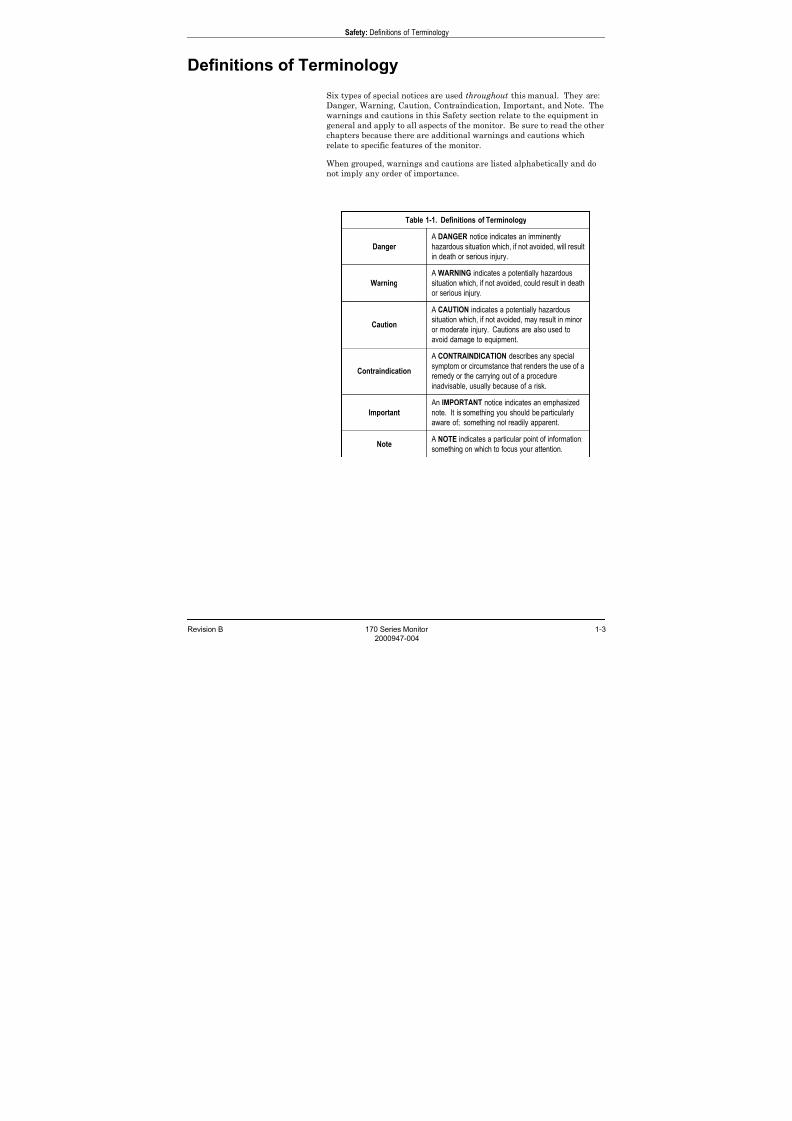
Six types of special notices are used throughout this manual. They are:
Danger, Warning, Caution, Contraindication, Important, and Note. The
warnings and cautions in this Safety section relate to the equipment in
general and apply to all aspects of the monitor. Be sure to read the otherchapters because there are additional warnings and cautions which
relate to specific features of the monitor.
When grouped, warnings and cautions are listed alphabetically and do
not imply any order of importance.
Table 1-1. Definitions of Terminology
Danger
A DANGER notice indicates an imminently
hazardous situation which, if not avoided, will result
in death or serious injury.
Warning
A WARNING indicates a potentially hazardous
situation which, if not avoided, could result in death
or serious injury.
Caution
A CAUTION indicates a potentially hazardous
situation which, if not avoided, may result in minor
or moderate injury. Cautions are also used to
avoid damage to equipment.
Contraindication
A CONTRAINDICATION describes any special
symptom or circumstance that renders the use of a
remedy or the carrying out of a procedureinadvisable, usually because of a risk.
Important
An IMPORTANT notice indicates an emphasized
note. It is something you should be particularly
aware of; something not readily apparent.
Note A NOTE indicates a particular point of information;
something on which to focus your attention.

7/25/2019 Serv. Corometrics 170
http://slidepdf.com/reader/full/serv-corometrics-170 10/254
1-4 170 Series Monitor Revision B
2000947-004
Safety: Monitor Contraindications, Warnings, and Precautions
Monitor Contraindications, Warnings, andPrecautions
Warnings
WARNINGS
ACCIDENTAL SPILLS—In the event that fluids are
accidentally spilled on the monitor, take the monitor out
of operation and inspect for damage.
APPLICATION—This monitor is not designed for direct
cardiac connection.
CONDUCTIVE CONNECTIONS—Avoid making any
conductive connections to applied parts (patient
connection) which are likely to degrade safety.
CONDUCTIVE PARTS—Ensure that the conductive
parts of the lead electrodes and associated connectors do
not contact other conductive parts including earth.
DEFIBRILLATION—During defibrillation, all personnel
must avoid contact with the patient and monitor to avoid
a dangerous shock hazard. In addition, proper placement
of the paddles in relation to the electrodes is required to
minimize harm to the patient.
ELECTRICAL SHOCK—To reduce the risk of electrical
shock, do not remove monitor cover. Refer servicing to
qualified personnel.
ELECTROMAGNETIC INTERFERENCE—Be aware
that strong electromagnetic fields may interfere with
monitor operation. Interference prevents the clear
reception of signals by the monitor. If the hospital is
close to a strong transmitter such as TV, AM or FM radio,
police or fire stations, a HAM radio operator, an airport,
or cellular phone, their signals could be picked up as
signals by the monitor. If you feel interference is
affecting the monitor, contact your Service
Representative to check the monitor in your
environment. Refer to page 1-8 for additional
information.
7/25/2019 Serv. Corometrics 170
http://slidepdf.com/reader/full/serv-corometrics-170 11/254
Revision B 170 Series Monitor 1-5
2000947-004
Safety: Monitor Contraindications, Warnings, and Precautions
WARNINGS
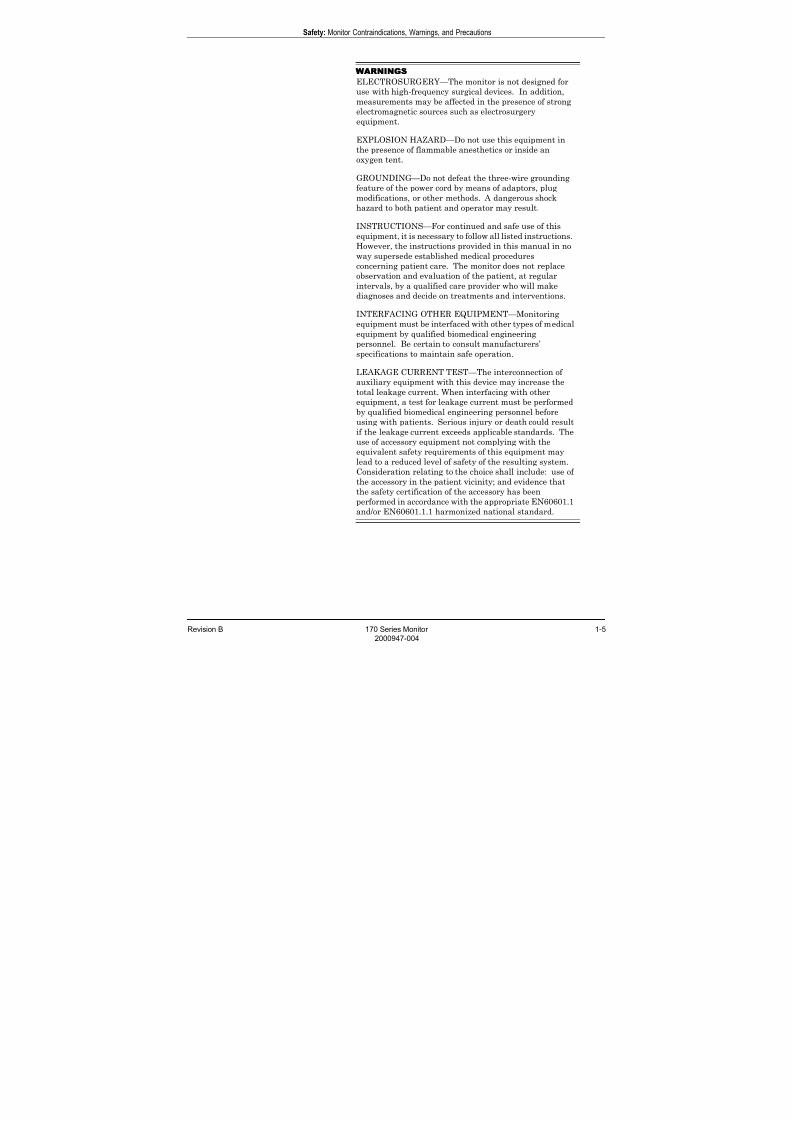
ELECTROSURGERY—The monitor is not designed for
use with high-frequency surgical devices. In addition,
measurements may be affected in the presence of strong
electromagnetic sources such as electrosurgery
equipment.
EXPLOSION HAZARD—Do not use this equipment in
the presence of flammable anesthetics or inside an
oxygen tent.
GROUNDING—Do not defeat the three-wire grounding
feature of the power cord by means of adaptors, plug
modifications, or other methods. A dangerous shock
hazard to both patient and operator may result.
INSTRUCTIONS—For continued and safe use of this
equipment, it is necessary to follow all listed instructions.
However, the instructions provided in this manual in no
way supersede established medical proceduresconcerning patient care. The monitor does not replace
observation and evaluation of the patient, at regular
intervals, by a qualified care provider who will make
diagnoses and decide on treatments and interventions.
INTERFACING OTHER EQUIPMENT—Monitoring
equipment must be interfaced with other types of medical
equipment by qualified biomedical engineering
personnel. Be certain to consult manufacturers’
specifications to maintain safe operation.
LEAKAGE CURRENT TEST—The interconnection of
auxiliary equipment with this device may increase thetotal leakage current. When interfacing with other
equipment, a test for leakage current must be performed
by qualified biomedical engineering personnel before
using with patients. Serious injury or death could result
if the leakage current exceeds applicable standards. The
use of accessory equipment not complying with the
equivalent safety requirements of this equipment may
lead to a reduced level of safety of the resulting system.
Consideration relating to the choice shall include: use of
the accessory in the patient vicinity; and evidence that
the safety certification of the accessory has been
performed in accordance with the appropriate EN60601.1
and/or EN60601.1.1 harmonized national standard.

7/25/2019 Serv. Corometrics 170
http://slidepdf.com/reader/full/serv-corometrics-170 12/254
1-6 170 Series Monitor Revision B
2000947-004
Safety: Monitor Contraindications, Warnings, and Precautions
WARNINGS
LINE ISOLATION MONITOR TRANSIENTS—Line
isolation monitor transients may resemble actual cardiac
waveforms, and thus cause incorrect heart rate
determinations and alarm activation (or inhibition).
STRANGULATION—Make sure all patient cables,
leadwires, and tubing are positioned away from the
patient’s head to minimize the risk of accidental
strangulation.
WATER BIRTHS—Do not use the monitor to directly
monitor patients during water births, in whirlpool or
submersion water baths, during showers, or in any other
situation where the mother is immersed in water. Doing
so may result in electrical shock hazard.
7/25/2019 Serv. Corometrics 170
http://slidepdf.com/reader/full/serv-corometrics-170 13/254
Revision B 170 Series Monitor 1-7
2000947-004
Safety: Monitor Contraindications, Warnings, and Precautions
Cautions
CAUTIONS
ANNUAL SERVICING—For continued safety and
performance of the monitor, it is recommended that the
calibration, accuracy, and electrical safety of the monitorbe verified on an annual basis by an GE Service
Representative.
DAILY TESTING—It is essential that the monitor and
accessories be inspected every day. It is recommended
practice to initiate the monitor’s self-test feature at the
beginning of each monitoring session; follow the
instructions in “Chapter 4, Setup Procedures”.
ENVIRONMENT—The performance of the monitor has
not been tested in certain areas, such as x-ray and
imaging suites. The monitor is not recommended for use
in these environments.
PERFORMANCE—Report all problems experienced with
the monitor. If the monitor is not working properly,
contact your Service Representative for service. The
monitor should not be used if it is not working properly.
PINCHING—Keep fingers clear of the paper roller
because the roller could pinch your fingers.
TRAPPING—Keep hands, hair, jewelry, and loose
clothing away from the paper roller because the roller
could trap these items.
TRIPPING—Arrange monitoring equipment so that
cords and cables do not present a tripping hazard.

7/25/2019 Serv. Corometrics 170
http://slidepdf.com/reader/full/serv-corometrics-170 14/254
1-8 170 Series Monitor Revision B
2000947-004
Safety: Monitor Contraindications, Warnings, and Precautions
Electromagnetic Interference
This device has been tested and found to comply with the limits for
medical devices to the IEC 601-1-2:1993, EN60601-1-2:1994, Medical
Device Directive 93/42/EEC. These limits are designed to provide
reasonable protection against harmful interference in a typical medical
installation.
However, because of the proliferation of radio-frequency transmitting
equipment and other sources of electrical noise in the health-care and
home environments (for example, cellular phones, mobile two-way
radios, electrical appliances), it is possible that high levels of such
interference due to close proximity or strength of a source, may result in
disruption of performance of this device.
This equipment generates, uses, and can radiate radio frequency energy
and, if not installed and used in accordance with these instructions, may
cause harmful interference with other devices in the vicinity. Disruption
or interference may be evidenced by erratic readings, cessation of
operation, or incorrect functioning. If this occurs, the site of use should besurveyed to determine the source of this disruption, and actions taken to
eliminate the source.
The user is encouraged to try to correct the interference by one or more of
the following measures:
Turn equipment in the vicinity off and on to isolate the offending
equipment.
Reorient or relocate the other receiving device.
Increase the separation between the interfering equipment and this
equipment.
If assistance is required, contact your GE Service Representative.
7/25/2019 Serv. Corometrics 170
http://slidepdf.com/reader/full/serv-corometrics-170 15/254
Revision B 170 Series Monitor 1-9
2000947-004
Safety: Equipment Symbols
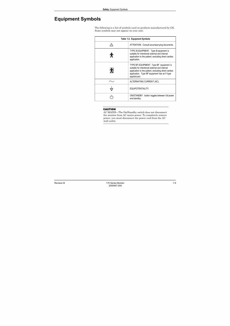
Equipment Symbols
The following is a list of symbols used on products manufactured by GE.
Some symbols may not appear on your unit.
CAUTION
AC MAINS—The On/Standby switch does not disconnect
the monitor from AC mains power. To completely remove
power, you must disconnect the power cord from the AC
wall outlet.
Table 1-2. Equipment Symbols
ATTENTION: Consult accompanying documents.
TYPE B EQUIPMENT. Type B equipment is
suitable for intentional external and internal
application to the patient, excluding direct cardiac
application.
TYPE BF EQUIPMENT. Type BF equipment is
suitable for intentional external and internal
application to the patient, excluding direct cardiac
application. Type BF equipment has an F-typeapplied part.
ALTERNATING CURRENT (AC).
EQUIPOTENTIALITY.
ON/STANDBY: button toggles between full power
and standby.

7/25/2019 Serv. Corometrics 170
http://slidepdf.com/reader/full/serv-corometrics-170 16/254
1-10 170 Series Monitor Revision B
2000947-004
Safety: Equipment Symbols
For your notes
7/25/2019 Serv. Corometrics 170
http://slidepdf.com/reader/full/serv-corometrics-170 17/254
Revision B 170 Series Monitor 2-1
2000947-004
Chapter 2
Introduction 2This section lists the indications for use for monitors in the 170 Series as
well as provides an explanation of the different patient monitoring
modalities.
This section summarizes the clinical applications of monitors in the 170Series:
Indications for Use . . . . . . . . . . . . . . . . . . . . . . . . . . . . . . . . . 2-2
Monitoring Methods . . . . . . . . . . . . . . . . . . . . . . . . . . . . . . . . 2-3
Features . . . . . . . . . . . . . . . . . . . . . . . . . . . . . . . . . . . . . . . . . 2-4
About Your Monitor . . . . . . . . . . . . . . . . . . . . . . . . . . . . . . . . 2-5

7/25/2019 Serv. Corometrics 170
http://slidepdf.com/reader/full/serv-corometrics-170 18/254
2-2 170 Series Monitor Revision B
2000947-004
Introduction: Indications for Use
Indications for Use
Models 171 and 172
Models 171 and 172 Fetal Monitors are indicated for use in the
monitoring of the fetus during the antepartum period as well as
throughout labor and delivery. Each monitor also has an optional
monitoring mode to detect fetal body movements.
Models 173 and 174
Models 173 and 174 Fetal Monitors are indicated for use in the
monitoring of the fetus throughout labor and delivery. Each monitor also
has an optional monitoring mode to detect fetal body movements.

7/25/2019 Serv. Corometrics 170
http://slidepdf.com/reader/full/serv-corometrics-170 19/254
Revision B 170 Series Monitor 2-3
2000947-004
Introduction: Monitoring Methods
Monitoring Methods
The following is a summary of all the clinical monitoring methods found
in the 170 Series.
Fetal Heart RateE
External Method, Pulsed Doppler UltrasoundUltrasound monitoring is available on all 170 Series Monitors. Models
171 and 173 provide a single ultrasound channel, while Models 172 and
174 provide two ultrasound channels.
Fetal heart rate can be measured externally using pulsed Doppler
Ultrasound. A transducer placed on the mother’s abdomen is used to
direct an ultrasonic beam toward the fetal heart and to sense Doppler
shifted echoes created by moving cardiac structures. A patented
autocorrelation process is used to determine the timing of successive
cardiac cycles. The resulting fetal heart rate (FHR) pattern is recorded
on the strip chart paper and the FHR appears on the digital display.
Internal Method, Direct Fetal Electrocardiogram (FECG)FECG is available on Models 173 and 174 only. The Model 173 provides a
dedicated FECG connector. The Model 174 provides a combi-connector
which can be used for either FECG or US.
FECG signals are obtained via a spiral electrode attached to the fetal
presenting part. FHR is computed on a beat-to-beat basis using the R-to-
R time interval of the QRS complexes. The instantaneous FHR pattern
is printed on the strip chart paper and the FHR appears on the digital
display.
Maternal Uterine Activity
External Method, Tocotransducer (TOCO)Maternal uterine activity is measured externally using a tocotransducer
(toco). Relative pressure within the uterus is measured using a
tocotransducer attached to the mother’s abdomen in the area of the
uterine fundus. The readings are plotted on the strip chart paper in a
relative scale from 0 to 100 as well as shown on the digital display. All
170 Series Monitors provide external uterine activity monitoring.
Internal Method, Intrauterine Pressure Catheter and Strain Gauge (IUP)IUP is available on Models 173 and 174 only.
Intrauterine pressure is measured using a transcervical catheter. The
pressure trend is plotted over the range of 0 to 100 mmHg and the
readings appear on the digital display.
7/25/2019 Serv. Corometrics 170
http://slidepdf.com/reader/full/serv-corometrics-170 20/254
2-4 170 Series Monitor Revision B
2000947-004
Introduction: Features
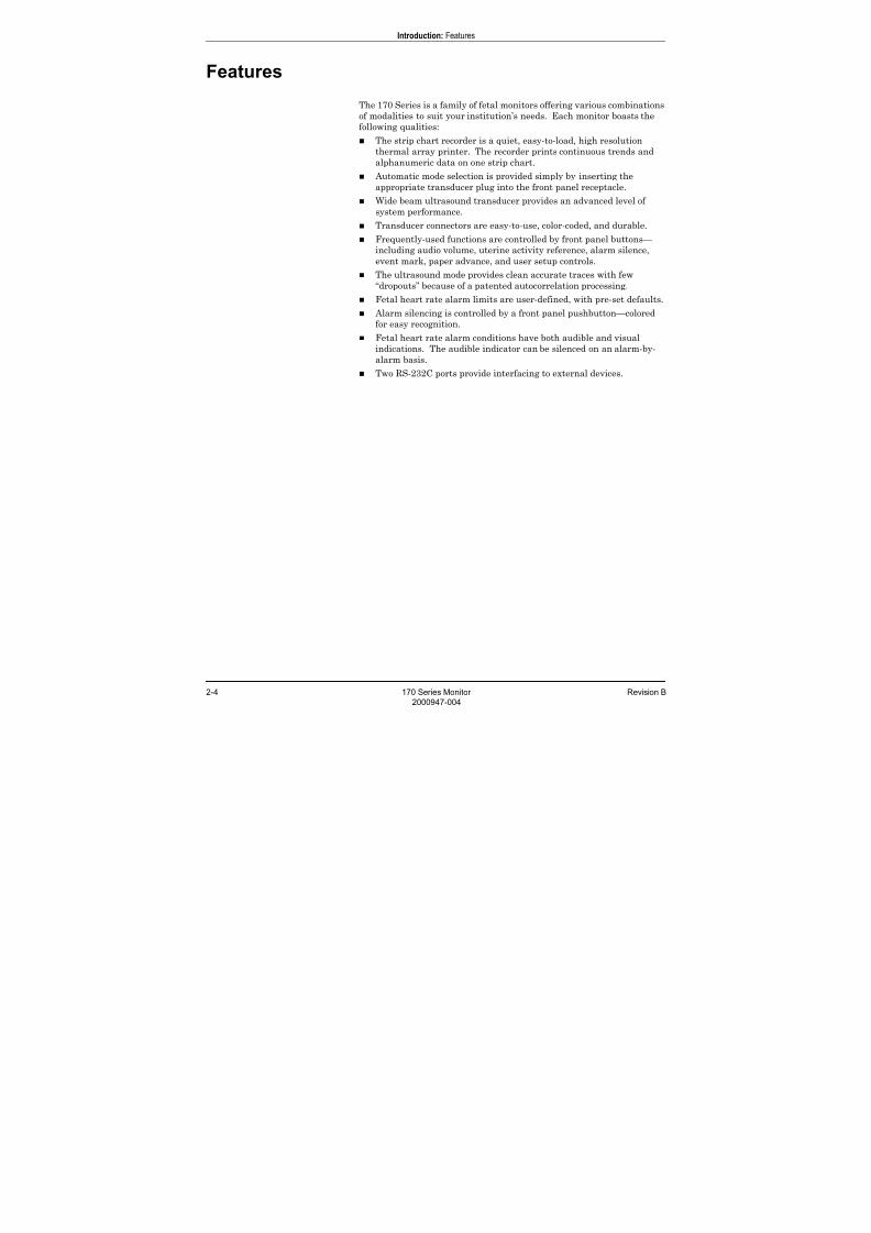
Features
The 170 Series is a family of fetal monitors offering various combinations
of modalities to suit your institution’s needs. Each monitor boasts the
following qualities:
The strip chart recorder is a quiet, easy-to-load, high resolutionthermal array printer. The recorder prints continuous trends and
alphanumeric data on one strip chart.
Automatic mode selection is provided simply by inserting the
appropriate transducer plug into the front panel receptacle.
Wide beam ultrasound transducer provides an advanced level of
system performance.
Transducer connectors are easy-to-use, color-coded, and durable.
Frequently-used functions are controlled by front panel buttons—
including audio volume, uterine activity reference, alarm silence,
event mark, paper advance, and user setup controls.
The ultrasound mode provides clean accurate traces with few“dropouts” because of a patented autocorrelation processing.
Fetal heart rate alarm limits are user-defined, with pre-set defaults.
Alarm silencing is controlled by a front panel pushbutton—colored
for easy recognition.
Fetal heart rate alarm conditions have both audible and visual
indications. The audible indicator can be silenced on an alarm-by-
alarm basis.
Two RS-232C ports provide interfacing to external devices.
7/25/2019 Serv. Corometrics 170
http://slidepdf.com/reader/full/serv-corometrics-170 21/254
Revision B 170 Series Monitor 2-5
2000947-004
Introduction: About Your Monitor
About Your Monitor
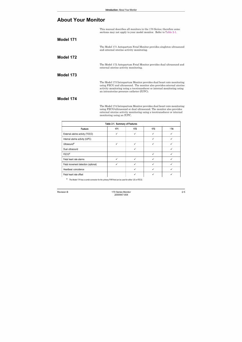
This manual describes all monitors in the 170 Series; therefore some
sections may not apply to your model monitor. Refer to Table 2-1.
Model 171
The Model 171 Antepartum Fetal Monitor provides singleton ultrasound
and external uterine activity monitoring.
Model 172
The Model 172 Antepartum Fetal Monitor provides dual ultrasound and
external uterine activity monitoring.
Model 173
The Model 173 Intrapartum Monitor provides dual heart rate monitoring
using FECG and ultrasound. The monitor also provides external uterine
activity monitoring using a tocotransducer or internal monitoring using
an intrauterine pressure catheter (IUPC).
Model 174
The Model 174 Intrapartum Monitor provides dual heart rate monitoring
using FECG/ultrasound or dual ultrasound. The monitor also provides
external uterine activity monitoring using a tocotransducer or internal
monitoring using an IUPC.
Table 2-1. Summary of Features
Feature 171 172 173 174
External uterine activity (TOCO)
Internal uterine activity (IUPC)
Ultrasounda
Dual ultrasound
FECGa
Fetal heart rate alarms
Fetal movement detection (optional)
Heartbeat coincidence
Fetal heart rate offset
aThe Model 174 has a combi-connector for the primary FHR that can be used for either US or FECG.

7/25/2019 Serv. Corometrics 170
http://slidepdf.com/reader/full/serv-corometrics-170 22/254
2-6 170 Series Monitor Revision B
2000947-004
For your notes

7/25/2019 Serv. Corometrics 170
http://slidepdf.com/reader/full/serv-corometrics-170 23/254
Revision B 170 Series Monitor 3-1
2000947-004
Chapter 3
Controls, Indicators, and
Connectors 3This section describes all possible controls, indicators, and connectors in
the 170 Series.
This section contains the following information:
Front Panel Controls . . . . . . . . . . . . . . . . . . . . . . . . . . . . . . . 3-2
Front Panel Displays and Indicators . . . . . . . . . . . . . . . . . . 3-6
Front Panel Connectors . . . . . . . . . . . . . . . . . . . . . . . . . . . . . 3-8
Strip Chart Recorder . . . . . . . . . . . . . . . . . . . . . . . . . . . . . . 3-12
Rear Panel Connectors. . . . . . . . . . . . . . . . . . . . . . . . . . . . . 3-14
7/25/2019 Serv. Corometrics 170
http://slidepdf.com/reader/full/serv-corometrics-170 24/254
3-2 170 Series Monitor Revision B
2000947-004
Controls, Indicators, and Connectors: Front Panel Controls
Front Panel Controls
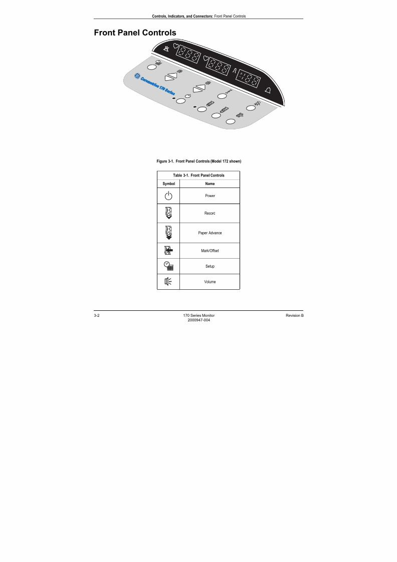
Figure 3-1. Front Panel Controls (Model 172 shown)
Table 3-1. Front Panel Controls
Symbol Name
Power
Record
Paper Advance
Mark/Offset
Setup
Volume
7/25/2019 Serv. Corometrics 170
http://slidepdf.com/reader/full/serv-corometrics-170 25/254
Revision B 170 Series Monitor 3-3
2000947-004
Controls, Indicators, and Connectors: Front Panel Controls
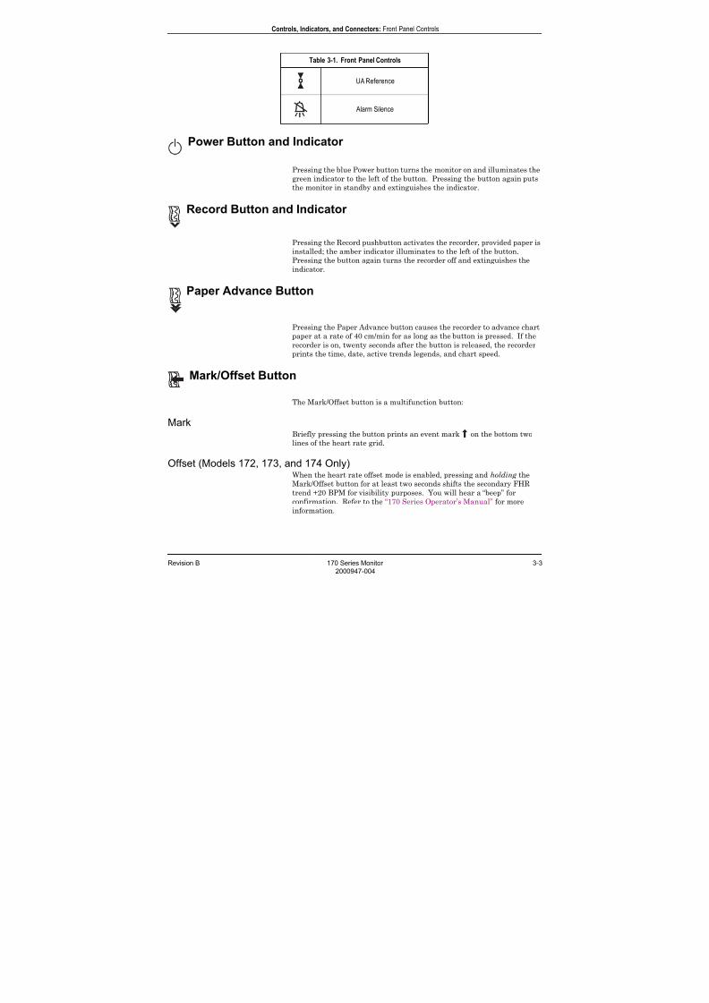
Power Button and Indicator
Pressing the blue Power button turns the monitor on and illuminates the
green indicator to the left of the button. Pressing the button again puts
the monitor in standby and extinguishes the indicator.
Record Button and Indicator
Pressing the Record pushbutton activates the recorder, provided paper is
installed; the amber indicator illuminates to the left of the button.
Pressing the button again turns the recorder off and extinguishes the
indicator.
Paper Advance Button
Pressing the Paper Advance button causes the recorder to advance chart
paper at a rate of 40 cm/min for as long as the button is pressed. If the
recorder is on, twenty seconds after the button is released, the recorder
prints the time, date, active trends legends, and chart speed.
Mark/Offset Button
The Mark/Offset button is a multifunction button:
MarkBriefly pressing the button prints an event mark on the bottom two
lines of the heart rate grid.
Offset (Models 172, 173, and 174 Only)When the heart rate offset mode is enabled, pressing and holding the
Mark/Offset button for at least two seconds shifts the secondary FHR
trend +20 BPM for visibility purposes. You will hear a “beep” for
confirmation. Refer to the “170 Series Operator’s Manual” for more
information.
UA Reference
Alarm Silence
Table 3-1. Front Panel Controls
7/25/2019 Serv. Corometrics 170
http://slidepdf.com/reader/full/serv-corometrics-170 26/254
3-4 170 Series Monitor Revision B
2000947-004
Controls, Indicators, and Connectors: Front Panel Controls
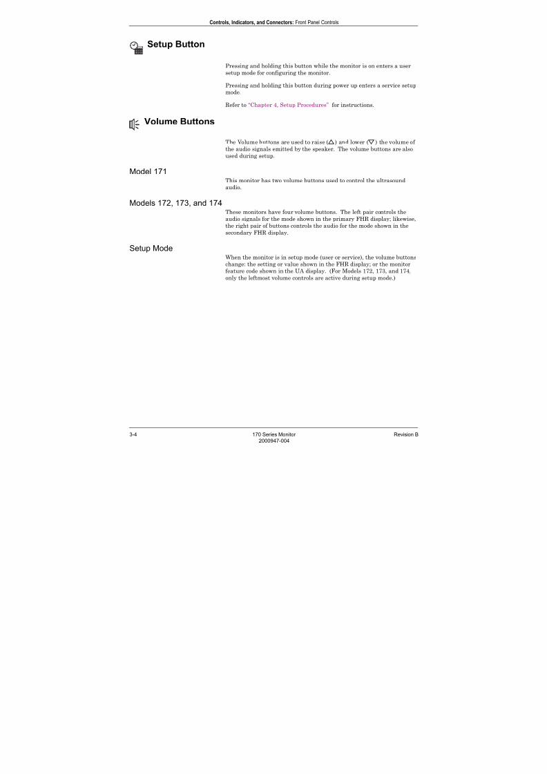
Setup Button
Pressing and holding this button while the monitor is on enters a user
setup mode for configuring the monitor.
Pressing and holding this button during power up enters a service setupmode.
Refer to “Chapter 4, Setup Procedures” for instructions.
Volume Buttons
The Volume buttons are used to raise ( ) and lower ( ) the volume of
the audio signals emitted by the speaker. The volume buttons are also
used during setup.
Model 171 This monitor has two volume buttons used to control the ultrasound
audio.
Models 172, 173, and 174These monitors have four volume buttons. The left pair controls the
audio signals for the mode shown in the primary FHR display; likewise,
the right pair of buttons controls the audio for the mode shown in the
secondary FHR display.
Setup ModeWhen the monitor is in setup mode (user or service), the volume buttons
change: the setting or value shown in the FHR display; or the monitorfeature code shown in the UA display. (For Models 172, 173, and 174,
only the leftmost volume controls are active during setup mode.)
7/25/2019 Serv. Corometrics 170
http://slidepdf.com/reader/full/serv-corometrics-170 27/254
Revision B 170 Series Monitor 3-5
2000947-004
Controls, Indicators, and Connectors: Front Panel Controls
UA Reference Button
The UA Reference button is used to set the uterine activity pressure
reference. This button is also used during setup.
Setting a Baseline for External Monitoring (Tocotransducer)Briefly pressing the UA Reference button sets the pressure baseline at a
preset default. The monitor is shipped from the factory with a default
setting of 10 relative units. Qualified service personnel can access a
service screen to set the default to 5, 10, 15, 20, or 25 relative units.
Pressing this button for more than two seconds causes the uterine
activity reference value to override the default setting and cycle through
all available selections: 5, 10, 15, 20, or 25 relative units, starting at the
default setting—until the button is released. While the button is held
down, the strip chart tracing remains unchanged. Once the button is
released, the recorder trace takes on this new value. This value is stored
as the new baseline for the currently measured uterine activity signal.
Setting a Baseline for Internal Monitoring (IUPC)Pressing the UA Reference button sets the pressure baseline at 0 mmHg.
NOTE IUPC monitoring is only available on Models 173 and 174.
Setup ModeWhen the monitor is in setup mode, the UA Reference button selects the
active display. Pressing the button alternates between the UA display
(which shows a monitor feature code) and the FHR display (which shows
the setting or value for the selected feature code). When the UA display
is active, the ± sign lights. When the FHR display is active, theheartbeat indicator lights.
Alarm Silence Button
This button is yellow for easy recognition. Pressing the Alarm Silence
button removes the audible indication of an individual fetal heart rate
alarm.
NOTE Silencing an alarm does not affect the visual indications.
7/25/2019 Serv. Corometrics 170
http://slidepdf.com/reader/full/serv-corometrics-170 28/254
3-6 170 Series Monitor Revision B
2000947-004
Controls, Indicators, and Connectors: Front Panel Displays and Indicators
Front Panel Displays and Indicators
Fetal Heart Rate Display(s) and Indicator(s)
FHR Display A three-digit yellow numeric display indicates the fetal heart rate in
beats per minute. The value flashes during an alarm condition.
Heartbeat Indicator A yellow heart shaped indicator flashes with each detected valid
heartbeat for the fetal heart.
Primary Versus Secondary (Models 172, 173, and 174 only)Refer to Table 3-2 for a summary of display positions relative to
connectors.
Uterine Activity Display
This green three-digit display indicates the uterine activity values.
Tocotransducer If uterine activity is measured using a tocotransducer, the uterine
activity value displays in relative units. A plus sign flashes when the
uterine activity value exceeds the strip chart range of 100 relative units.
IUP (Models 173 and 174 Only)
If uterine activity is measured using an intrauterine pressure catheter ora strain gauge pressure transducer, the uterine activity value displays in
mmHg.
.
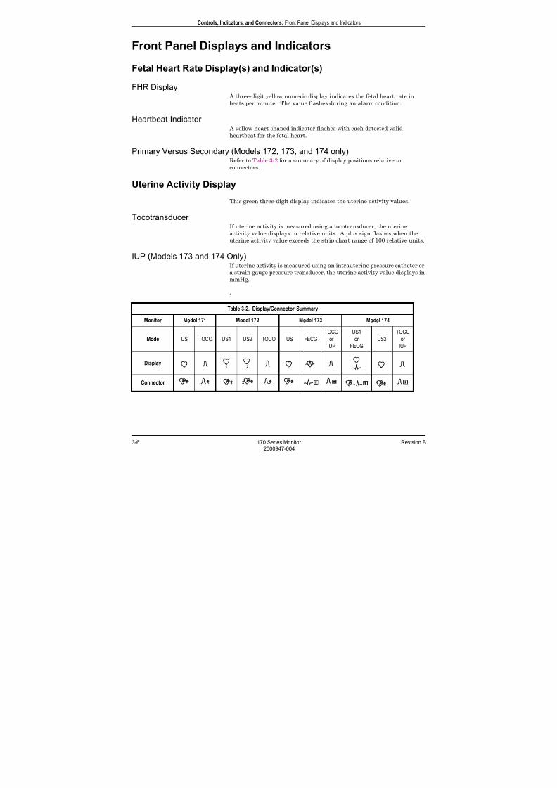
Table 3-2. Display/Connector Summary
Monitor Model 171 Model 172 Model 173 Model 174
Mode US TOCO US1 US2 TOCO US FECG
TOCO
or
IUP
US1
or
FECG
US2
TOCO
or
IUP
Display
Connector

7/25/2019 Serv. Corometrics 170
http://slidepdf.com/reader/full/serv-corometrics-170 29/254
Revision B 170 Series Monitor 3-7
2000947-004
Controls, Indicators, and Connectors: Front Panel Displays and Indicators
Alarms Disabled Indicator
This yellow indicator illuminates when all alarms have been disabled.
The indicator is unlit when alarms are enabled. Refer to “Chapter 4,
Setup Procedures” for information on enabling/disabling alarms.
Audio Alarm Indicator
Active Patient AlarmsFor active patient alarms, this yellow indicator flashes; it continues to
flash even if the alarm is silenced.
Resolved Patient AlarmsFor resolved patient alarms, the indicator continues to flash until you
silence the alarm. This ensures that the alarm is acknowledged by a
clinician.
Signal Quality AlarmsFor signal quality alarms, the indicator flashes during an active alarm
and turns off as soon as the condition is resolved. The indicator is
unaffected by silencing the audio alarm.
7/25/2019 Serv. Corometrics 170
http://slidepdf.com/reader/full/serv-corometrics-170 30/254
3-8 170 Series Monitor Revision B
2000947-004
Controls, Indicators, and Connectors: Front Panel Connectors
Front Panel Connectors
Model 171 Connectors
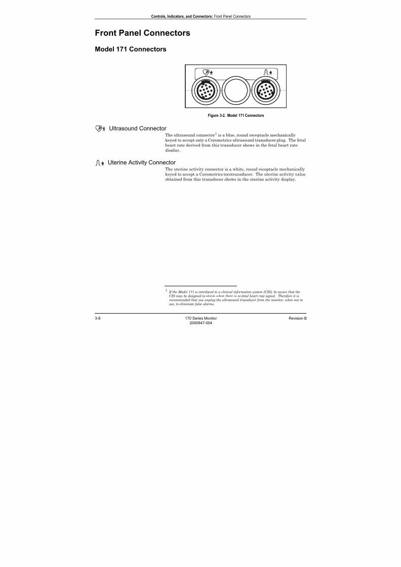
Figure 3-2. Model 171 Connectors
Ultrasound Connector The ultrasound connector1 is a blue, round receptacle mechanically
keyed to accept only a Corometrics ultrasound transducer plug. The fetal
heart rate derived from this transducer shows in the fetal heart rate
display.
Uterine Activity Connector The uterine activity connector is a white, round receptacle mechanically
keyed to accept a Corometrics tocotransducer. The uterine activity value
obtained from this transducer shows in the uterine activity display.
1If the Model 171 is interfaced to a clinical information system (CIS), be aware that the
CIS may be designed to alarm when there is no fetal heart rate signal. Therefore it is
recommended that you unplug the ultrasound transducer from the monitor, when not in
use, to eliminate false alarms.

7/25/2019 Serv. Corometrics 170
http://slidepdf.com/reader/full/serv-corometrics-170 31/254
Revision B 170 Series Monitor 3-9
2000947-004
Controls, Indicators, and Connectors: Front Panel Connectors
Model 172 Connectors
Figure 3-3. Model 172 Connectors
Primary Ultrasound Connector The primary ultrasound connector1 is a blue, round receptacle
mechanically keyed to accept only a Corometrics ultrasound transducerplug. The fetal heart rate derived from this transducer shows in the
primary fetal heart rate display.
Secondary Ultrasound Connector The secondary ultrasound connector1 is a blue, round receptacle identical
to the primary ultrasound connector described above. The fetal heart
rate derived from this connector displays in the secondary fetal heart
rate display.
Uterine Activity Connector
The uterine activity connector is a white, round receptacle mechanicallykeyed to accept a Corometrics tocotransducer. The uterine activity value
obtained from this transducer shows in the uterine activity display.
1If the Model 172 is interfaced to a clinical information system (CIS), be aware that the
CIS may be designed to alarm when there is no fetal heart rate signal. Therefore it is
recommended that you unplug the ultrasound transducer(s) from the monitor, when not
in use, to eliminate false alarms.

7/25/2019 Serv. Corometrics 170
http://slidepdf.com/reader/full/serv-corometrics-170 32/254
3-10 170 Series Monitor Revision B
2000947-004
Controls, Indicators, and Connectors: Front Panel Connectors
Model 173 Connectors
Figure 3-4. Model 173 Connectors
Ultrasound Connector The ultrasound connector1 is a blue, round receptacle mechanically
keyed to accept only a Corometrics ultrasound transducer plug. The fetal
heart rate derived from this transducer shows in the primary fetal heart
display.
FECG Connector The FECG connector
1 is a dark grey, round receptacle mechanically
keyed to accept a Corometrics FECG cable/legplate plug. The fetal heart
rate derived from the spiral electrode displays in the secondary fetal
heart rate display.
Uterine Activity Connector
The uterine activity connector is a white, round receptacle mechanicallykeyed to accept a Corometrics tocotransducer, a Corometrics strain
gauge transducer plug, or any intrauterine pressure catheter with
compatible cable plug. The uterine activity value obtained from this
transducer shows in the uterine activity display.
1If the Model 173 is interfaced to a clinical information system (CIS), be aware that the
CIS may be designed to alarm when there is no fetal heart rate signal. Therefore it is
recommended that you unplug the ultrasound and/or FECG transducers from the
monitor, when not in use, to eliminate false alarms.
7/25/2019 Serv. Corometrics 170
http://slidepdf.com/reader/full/serv-corometrics-170 33/254
Revision B 170 Series Monitor 3-11
2000947-004
Controls, Indicators, and Connectors: Front Panel Connectors
Model 174 Connectors
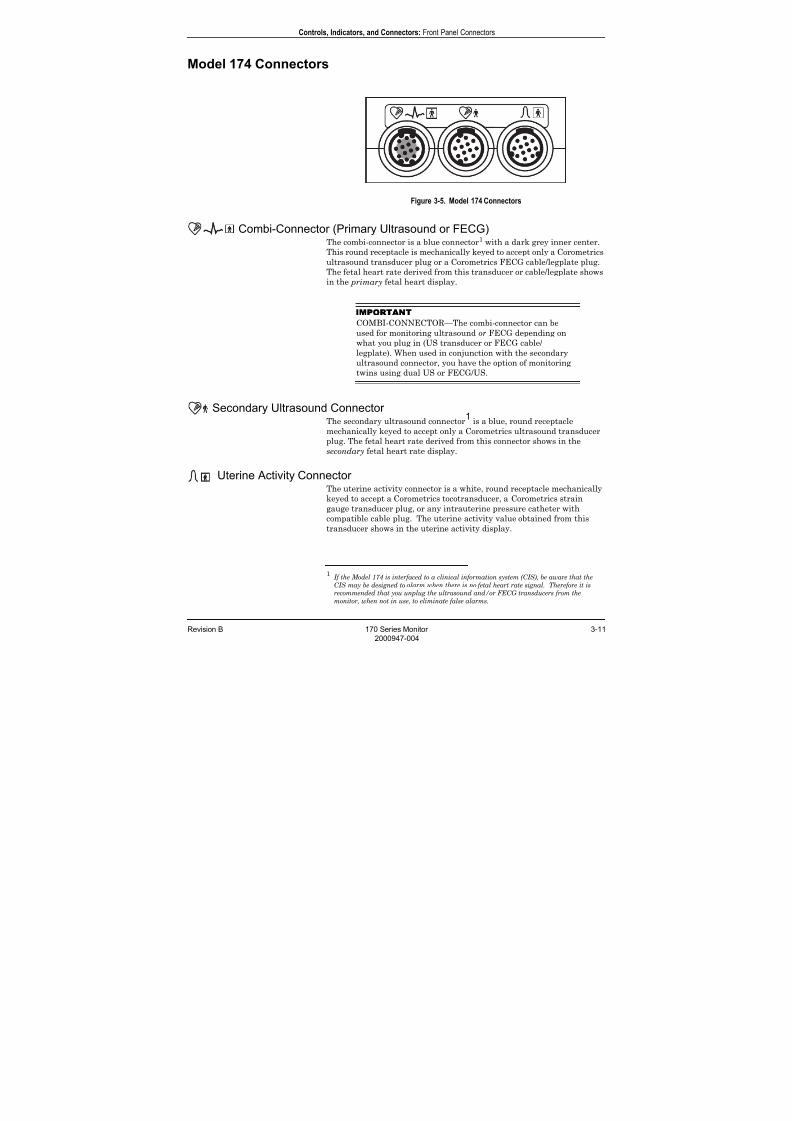
Figure 3-5. Model 174 Connectors
Combi-Connector (Primary Ultrasound or FECG)The combi-connector is a blue connector1 with a dark grey inner center.
This round receptacle is mechanically keyed to accept only a Corometricsultrasound transducer plug or a Corometrics FECG cable/legplate plug.
The fetal heart rate derived from this transducer or cable/legplate shows
in the primary fetal heart display.
IMPORTANT
COMBI-CONNECTOR—The combi-connector can be
used for monitoring ultrasound or FECG depending on
what you plug in (US transducer or FECG cable/
legplate). When used in conjunction with the secondary
ultrasound connector, you have the option of monitoring
twins using dual US or FECG/US.
Secondary Ultrasound Connector The secondary ultrasound connector
1 is a blue, round receptacle
mechanically keyed to accept only a Corometrics ultrasound transducer
plug. The fetal heart rate derived from this connector shows in the
secondary fetal heart rate display.
Uterine Activity Connector The uterine activity connector is a white, round receptacle mechanically
keyed to accept a Corometrics tocotransducer, a Corometrics strain
gauge transducer plug, or any intrauterine pressure catheter withcompatible cable plug. The uterine activity value obtained from this
transducer shows in the uterine activity display.
1If the Model 174 is interfaced to a clinical information system (CIS), be aware that the
CIS may be designed to alarm when there is no fetal heart rate signal. Therefore it is
recommended that you unplug the ultrasound and/or FECG transducers from the
monitor, when not in use, to eliminate false alarms.
7/25/2019 Serv. Corometrics 170
http://slidepdf.com/reader/full/serv-corometrics-170 34/254
3-12 170 Series Monitor Revision B
2000947-004
Controls, Indicators, and Connectors: Strip Chart Recorder
Strip Chart Recorder
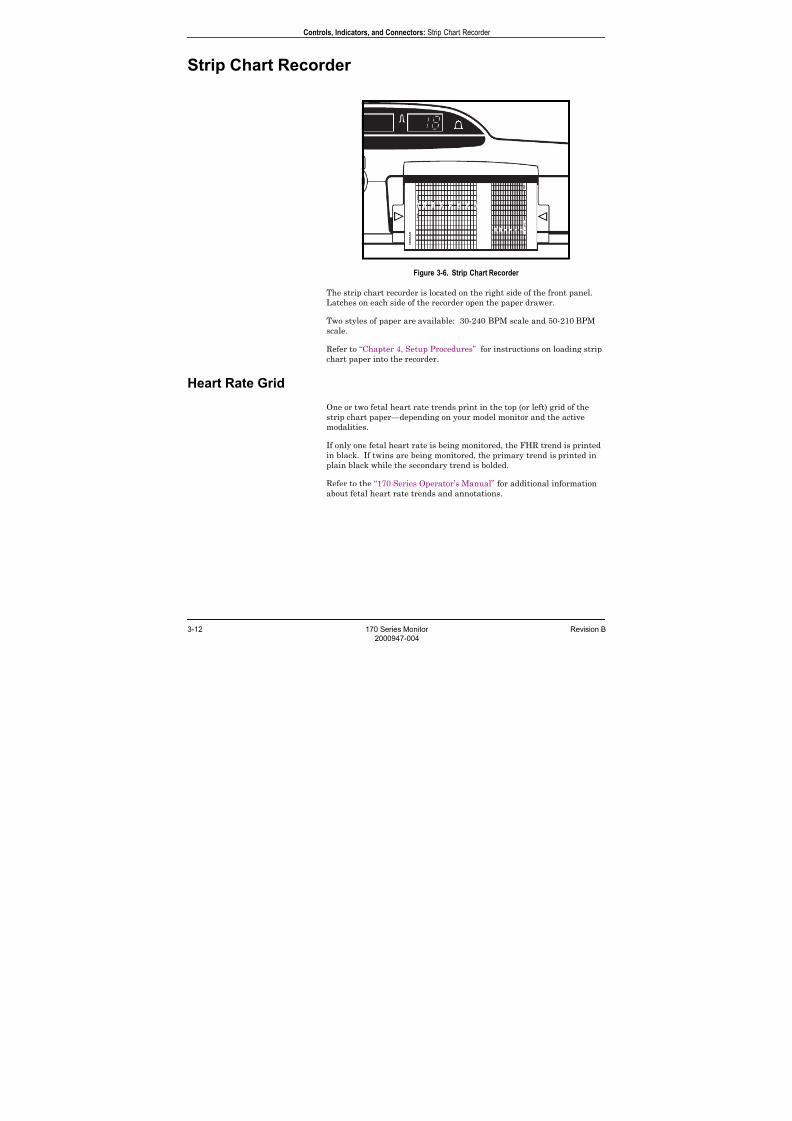
Figure 3-6. Strip Chart Recorder
The strip chart recorder is located on the right side of the front panel.
Latches on each side of the recorder open the paper drawer.
Two styles of paper are available: 30-240 BPM scale and 50-210 BPM
scale.
Refer to “Chapter 4, Setup Procedures” for instructions on loading strip
chart paper into the recorder.
Heart Rate Grid
One or two fetal heart rate trends print in the top (or left) grid of the
strip chart paper—depending on your model monitor and the active
modalities.
If only one fetal heart rate is being monitored, the FHR trend is printed
in black. If twins are being monitored, the primary trend is printed in
plain black while the secondary trend is bolded.
Refer to the “170 Series Operator’s Manual” for additional information
about fetal heart rate trends and annotations.
7/25/2019 Serv. Corometrics 170
http://slidepdf.com/reader/full/serv-corometrics-170 35/254
Revision B 170 Series Monitor 3-13
2000947-004
Controls, Indicators, and Connectors: Strip Chart Recorder
Uterine Activity Grid
The uterine activity trend prints in black on the bottom (or right) grid of
the strip chart paper.
Refer to the “170 Series Operator’s Manual” for more information about
uterine activity trends and annotations.
Annotation Area
An annotation area is provided between the fetal heart rate and uterine
activity grids.
7/25/2019 Serv. Corometrics 170
http://slidepdf.com/reader/full/serv-corometrics-170 36/254
3-14 170 Series Monitor Revision B
2000947-004
Controls, Indicators, and Connectors: Rear Panel Connectors
Rear Panel Connectors
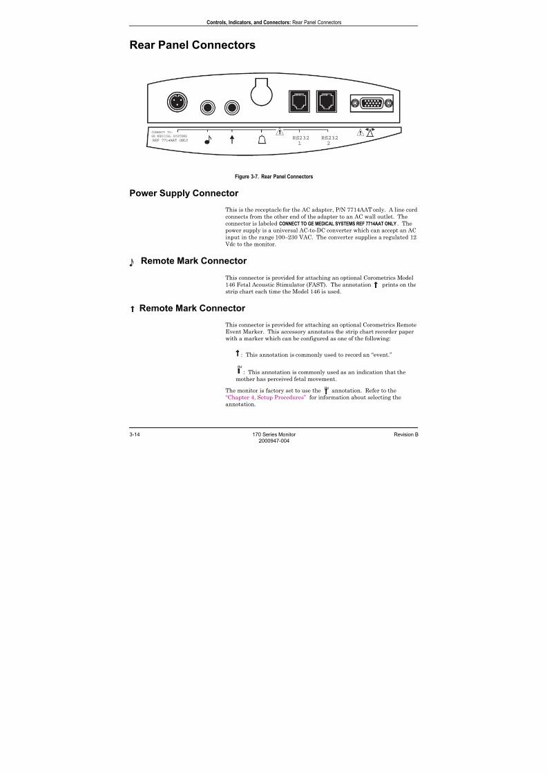
Figure 3-7. Rear Panel Connectors
Power Supply Connector
This is the receptacle for the AC adapter, P/N 7714AAT only. A line cord
connects from the other end of the adapter to an AC wall outlet. The
connector is labeled CONNECT TO GE MEDICAL SYSTEMS REF 7714AAT ONLY. The
power supply is a universal AC-to-DC converter which can accept an AC
input in the range 100–230 VAC. The converter supplies a regulated 12
Vdc to the monitor.
Remote Mark Connector This connector is provided for attaching an optional Corometrics Model
146 Fetal Acoustic Stimulator (FAST). The annotation prints on the
strip chart each time the Model 146 is used.
Remote Mark Connector
This connector is provided for attaching an optional Corometrics Remote
Event Marker. This accessory annotates the strip chart recorder paper
with a marker which can be configured as one of the following:
: This annotation is commonly used to record an “event.”
: This annotation is commonly used as an indication that the
mother has perceived fetal movement.
The monitor is factory set to use the annotation. Refer to the
“Chapter 4, Setup Procedures” for information about selecting the
annotation.
RS232 RS232
1 2
CONNECT TO:
GE MEDICAL SYSTEMS
REF 7714AAT ONLY
7/25/2019 Serv. Corometrics 170
http://slidepdf.com/reader/full/serv-corometrics-170 37/254
Revision B 170 Series Monitor 3-15
2000947-004
Controls, Indicators, and Connectors: Rear Panel Connectors
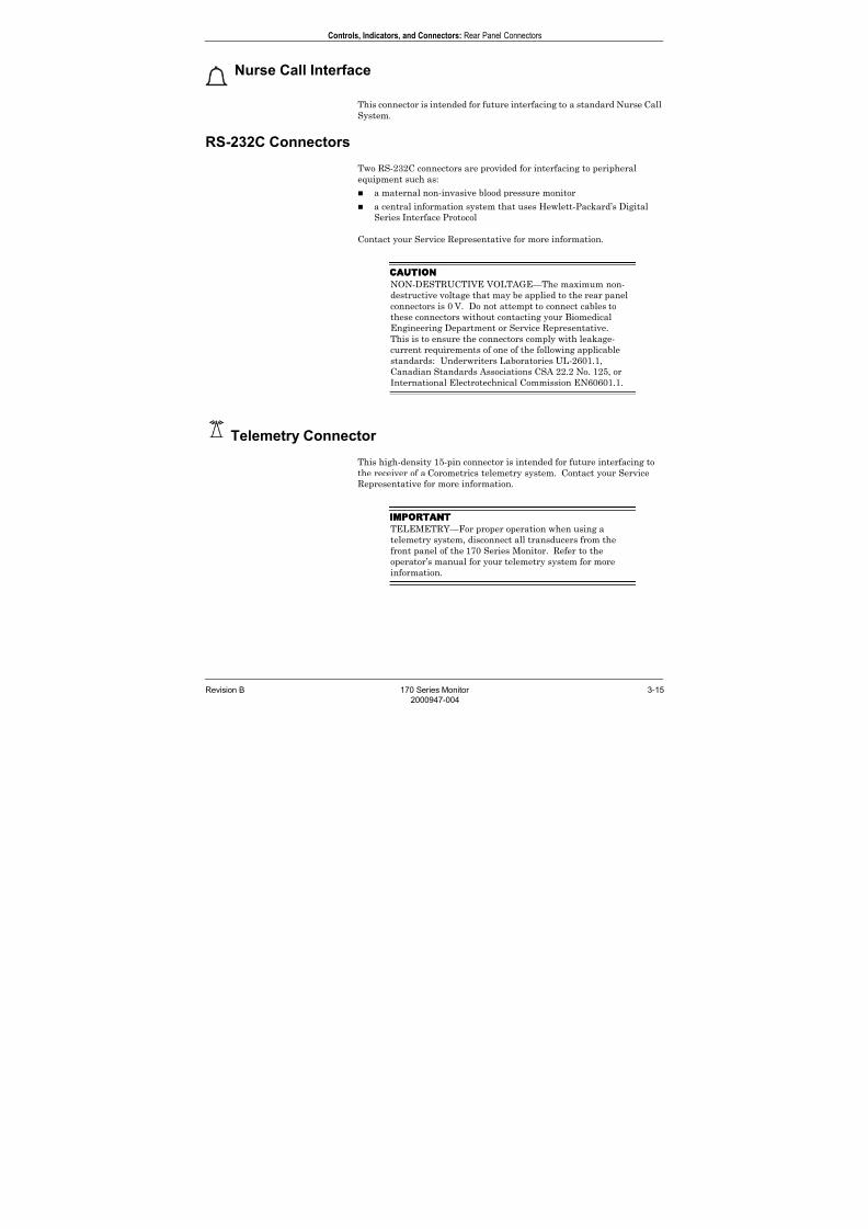
Nurse Call Interface
This connector is intended for future interfacing to a standard Nurse Call
System.
RS-232C Connectors
Two RS-232C connectors are provided for interfacing to peripheral
equipment such as:
a maternal non-invasive blood pressure monitor
a central information system that uses Hewlett-Packard’s Digital
Series Interface Protocol
Contact your Service Representative for more information.
CAUTION
NON-DESTRUCTIVE VOLTAGE—The maximum non-
destructive voltage that may be applied to the rear panel
connectors is 0 V. Do not attempt to connect cables to
these connectors without contacting your Biomedical
Engineering Department or Service Representative.
This is to ensure the connectors comply with leakage-
current requirements of one of the following applicable
standards: Underwriters Laboratories UL-2601.1,
Canadian Standards Associations CSA 22.2 No. 125, or
International Electrotechnical Commission EN60601.1.
Telemetry Connector
This high-density 15-pin connector is intended for future interfacing to
the receiver of a Corometrics telemetry system. Contact your Service
Representative for more information.
IMPORTANT
TELEMETRY—For proper operation when using a
telemetry system, disconnect all transducers from the
front panel of the 170 Series Monitor. Refer to the
operator’s manual for your telemetry system for more
information.

7/25/2019 Serv. Corometrics 170
http://slidepdf.com/reader/full/serv-corometrics-170 38/254
3-16 170 Series Monitor Revision B
2000947-004
For your notes

7/25/2019 Serv. Corometrics 170
http://slidepdf.com/reader/full/serv-corometrics-170 39/254
Revision B 170 Series Monitor 4-1
2000947-004
Chapter 4
Setup Procedures 4This section contains information about configuring a 170 Series Monitor
to meet the individual needs of your clinic or hospital. Use of the monitor
will vary according to the accessories attached to it, the clinical
applications in which it is used, and the personal preferences of the
users.
This chapter lists all available user setup options in the monitor and
provides step-by-step instructions for making selections:
Loading Strip Chart Paper . . . . . . . . . . . . . . . . . . . . . . . . . . 4-2
Turning the Monitor On . . . . . . . . . . . . . . . . . . . . . . . . . . . . 4-7
Recorder Test . . . . . . . . . . . . . . . . . . . . . . . . . . . . . . . . . . . . . 4-9
Customizing the Monitor . . . . . . . . . . . . . . . . . . . . . . . . . . . 4-10
Printing a Summary of Configuration Settings . . . . . . . . . 4-17
Quick Reference Card . . . . . . . . . . . . . . . . . . . . . . . . . . . . . 4-18
Flasher Software Utility Upgrade. . . . . . . . . . . . . . . . . . . . 4-20
7/25/2019 Serv. Corometrics 170
http://slidepdf.com/reader/full/serv-corometrics-170 40/254
4-2 170 Series Monitor Revision B
2000947-004
Setup Procedures: Loading Strip Chart Paper
Loading Strip Chart Paper
The required paper for use with the 170 Series Monitor is:
catalog number (REF) 4305AAO/CAO
(HR scale of 30–240 BPM); or catalog number (REF) 4305BAO/DAO
(HR scale of 50–210 BPM).
CAUTIONS
LOADING PAPER—The instructions for loading paper
into a 120 or 170 Series Monitor are different than the
instructions for loading paper into other Corometrics
monitors with which you may be familiar. Improper
loading can cause paper jams. Follow the instructions
carefully.
PAPER TYPE—Do not use non-Corometrics paper orpaper designed for use with other Corometrics monitors.
Using paper other than catalog number (REF) 4305AAO/
BAO/CAO/DAO: may produce inferior print quality;
could result in permanent damage to the recorder’s print
head; and may void your warranty.
STORAGE/TRANSPORT—Paper should be installed in
the monitor’s strip chart recorder at all times. This
reduces particle build up on the printhead and facilitates
opening the recorder door.
To protect against paper jams, the 170 Series recorder contains a paper-loading sensor which detects if the paper has been incorrectly loaded.
When the recorder detects a paper-load–error condition:
the recorder will not print;
the Record indicator flashes on and off every second; and
three short beeps (low tones) sound every three seconds at a fixed
volume.
The most likely cause of a paper-load–error condition is that you loaded
the paper with the black squares facing up. The correct method is to load
the paper with the black squares down, as explained later in this section.
7/25/2019 Serv. Corometrics 170
http://slidepdf.com/reader/full/serv-corometrics-170 41/254
Revision B 170 Series Monitor 4-3
2000947-004
Setup Procedures: Loading Strip Chart Paper
To install Corometrics catalog number (REF) 4305AAO/BAO/CAO/DAO
chart paper in the 170 Series Monitor, follow these steps:
CAUTION
LOADING PAPER—Paper loading instructions for a 170
or 120 Series Monitor are different than otherCorometrics monitors with which you may be familiar.
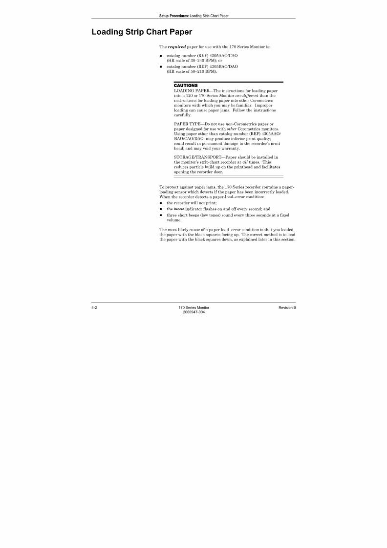
1. Press on each side of the paper drawer to release the drawer latches.
Figure 4-1. Releasing the Drawer Latches
2. Slide the paper drawer out toward you.
Figure 4-2. Opening the Paper Drawer
3. Remove the plastic wrapper from the paper and discard.

7/25/2019 Serv. Corometrics 170
http://slidepdf.com/reader/full/serv-corometrics-170 42/254
4-4 170 Series Monitor Revision B
2000947-004
Setup Procedures: Loading Strip Chart Paper
4. Fan the pack of Z-fold paper on all sides to loosen any folds and to
ensure proper feed of the paper throughout the recorder.
Figure 4-3. Fanning the Paper
5. Hold the package of paper so that:
the black squares are on the bottom of the pack; and
the Information Technologies name and page numbers are on the
left side of the pack.
NOTE The black squares indicate the end of the recorder paper. When
the black squares appear, the strip chart recorder has
approximately 20 minutes of paper remaining, when running at
a speed of 3 cm/min.
Figure 4-4. Orienting the Paper
7/25/2019 Serv. Corometrics 170
http://slidepdf.com/reader/full/serv-corometrics-170 43/254
Revision B 170 Series Monitor 4-5
2000947-004
Setup Procedures: Loading Strip Chart Paper
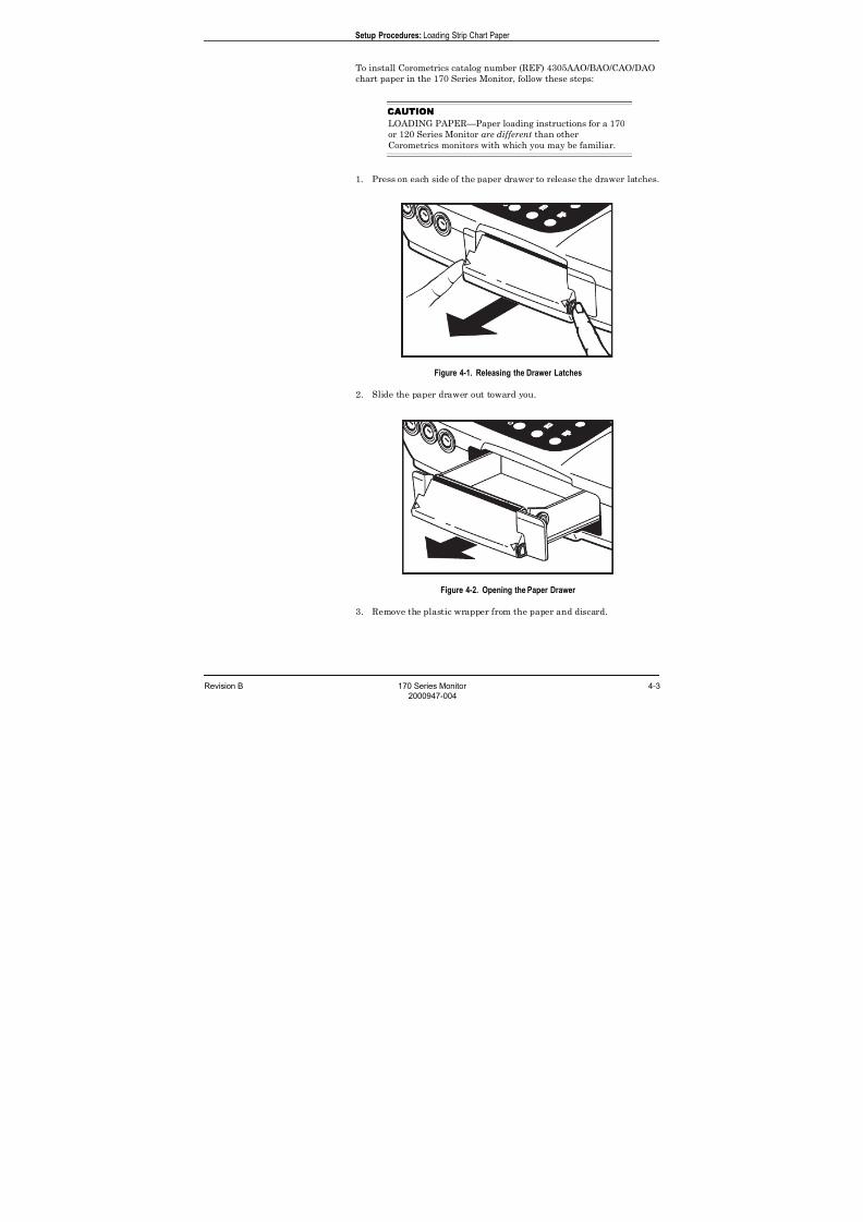
6. Unfold two sheets from the top of the pack so that they extend
toward you.
Figure 4-5. Creating a Paper Leader
7. Place the pack in the drawer so that the pack is laying flat in the
bottom of the paper tray.
Figure 4-6. Inserting the Paper
7/25/2019 Serv. Corometrics 170
http://slidepdf.com/reader/full/serv-corometrics-170 44/254
4-6 170 Series Monitor Revision B
2000947-004
Setup Procedures: Loading Strip Chart Paper
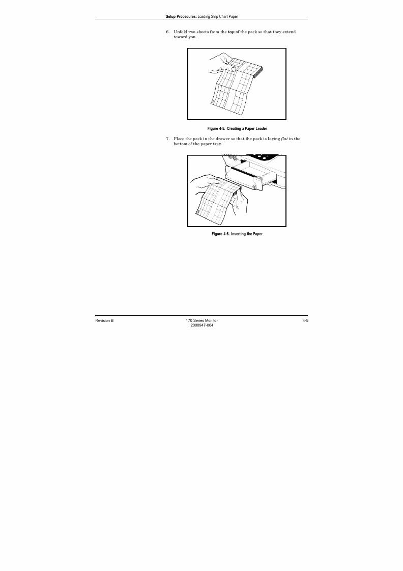
8. Pull the paper leader taut at an angle between remaining pack and
the paper guides. The balance of the paper pack should stay flat in
the drawer as shown in Figure 4-7. (The paper guides are shown in
Figure 4-8.)
Figure 4-7. Paper Drawer Side Cutaway View
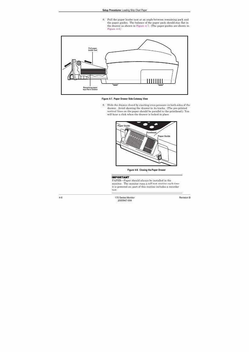
9. Slide the drawer closed by exerting even pressure on both sides of the
drawer. Avoid skewing the drawer in its tracks. (The pre-printed
vertical lines on the paper should be parallel to the printhead.) You
will hear a click when the drawer is locked in place.
Figure 4-8. Closing the Paper Drawer
IMPORTANT
PAPER—Paper should always be installed in the
monitor. The monitor runs a self-test routine each time
it is powered on; part of this routine includes a recorder
test.
7/25/2019 Serv. Corometrics 170
http://slidepdf.com/reader/full/serv-corometrics-170 45/254
Revision B 170 Series Monitor 4-7
2000947-004
Setup Procedures: Turning the Monitor On
Turning the Monitor On
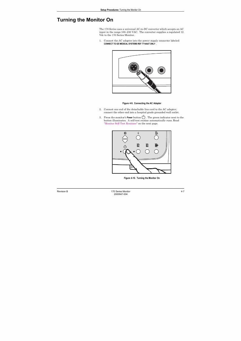
The 170 Series uses a universal AC-to-DC converter which accepts an AC
input in the range 100–230 VAC. The converter supplies a regulated 12
Vdc to the 170 Series Monitor.
1. Connect the AC adapter into the power supply connector labeled:
CONNECT TO GE MEDICAL SYSTEMS REF 7714AAT ONLY .
Figure 4-9. Connecting the AC Adapter
2. Connect one end of the detachable line cord to the AC adapter;
connect the other end into a hospital grade grounded wall outlet.
3. Press the monitor’s Power button . The green indicator next to the
button illuminates. A self-test routine automatically runs. Read
"Monitor Self-Test Routines" on the next page.
Figure 4-10. Turning the Monitor On
7/25/2019 Serv. Corometrics 170
http://slidepdf.com/reader/full/serv-corometrics-170 46/254
4-8 170 Series Monitor Revision B
2000947-004
Setup Procedures: Monitor Self-Test Routines
Monitor Self-Test Routines
NOTE Ensure paper is installed in the recorder in order to verify a
successful recorder test.
Each 170 Series Monitor contains a self-test routine which checks the
internal circuitry of the monitor, the displays and indicators, and the
strip chart recorder. The self-test routine is automatically initiated each
time you turn on the monitor.
CAUTION
SELF-TEST FAILURE—If there is any problem with the
self-test routine, turn off the monitor and remove it from
operation. Notify your Biomedical Engineering
Department or Service Representative.
After completion of a successful self-test routine, the monitor is ready foruse.
NOTE If the recorder was off at the time the monitor was turned off, the
test routine will turn the recorder on, then turn it off after the
tests are complete. If the recorder was on at the time the monitor
was turned off, the tests will be performed and the recorder will
remain on.
Table 4-1. Summary of Self-Test Routines
Test Description What to Verify
Display/Indicator Test: All displays and indicators
illuminate.
Ensure all indicators and each segment of the displays
illuminate throughout the entire self-test routine.
Internal Test: The internal circuitry of the monitor is
verified.
Make sure the monitor performs the recorder test. If
there is a problem with the internal circuitry, the recorder
test will not be performed.
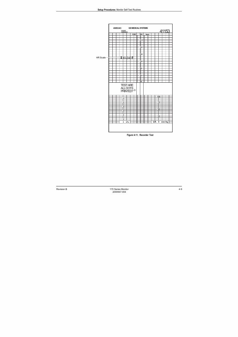
Recorder Test: The following message prints on the
strip chart paper: TEST: ARE ALL DOTS PRINTED?
Three continuous lines are drawn across the strip chart
recorder paper, testing the integrity of the printhead.
See Figure 4-11.
Ensure that the lines are printed in the correct positions
on the paper. Verify that the lines are continuous and no
gaps appear on the traces.
7/25/2019 Serv. Corometrics 170
http://slidepdf.com/reader/full/serv-corometrics-170 47/254
Revision B 170 Series Monitor 4-9
2000947-004
Setup Procedures: Monitor Self-Test Routines
Figure 4-11. Recorder Test
HR Scale

7/25/2019 Serv. Corometrics 170
http://slidepdf.com/reader/full/serv-corometrics-170 48/254
4-10 170 Series Monitor Revision B
2000947-004
Setup Procedures: Customizing the Monitor
Customizing the Monitor
User Setup Mode
The monitor includes a user setup mode where you can:
enable/disable alarm functionality
set the high alarm limit for the fetal heart rate
set the low alarm limit for the fetal heart rate
set the alarm volume
set the time and date
Service Setup Mode
The monitor includes a service setup mode where you can access all user
setup modes as well as the following:
enable/disable fetal movement detection
(if purchased and installed)
select the language for printing on the strip chart paper
set the chart speed
select the paper scale
choose a communication mode for each rear panel
communications port
set the baud rate for each communications port
select the remote mark annotation style
enable/disable fetal heart rate offset
(Models 172, 173, and 174 only)
enable/disable ECG artifact elimination
(Models 173 and 174 only)
enable/disable heartbeat coincidence
(Models 172, 173, and 174 only)
set the default UA reference value
perform a recorder alignment test
print the software version number along with a summary of all
current configuration settings
7/25/2019 Serv. Corometrics 170
http://slidepdf.com/reader/full/serv-corometrics-170 49/254
Revision B 170 Series Monitor 4-11
2000947-004
Setup Procedures: Customizing the Monitor
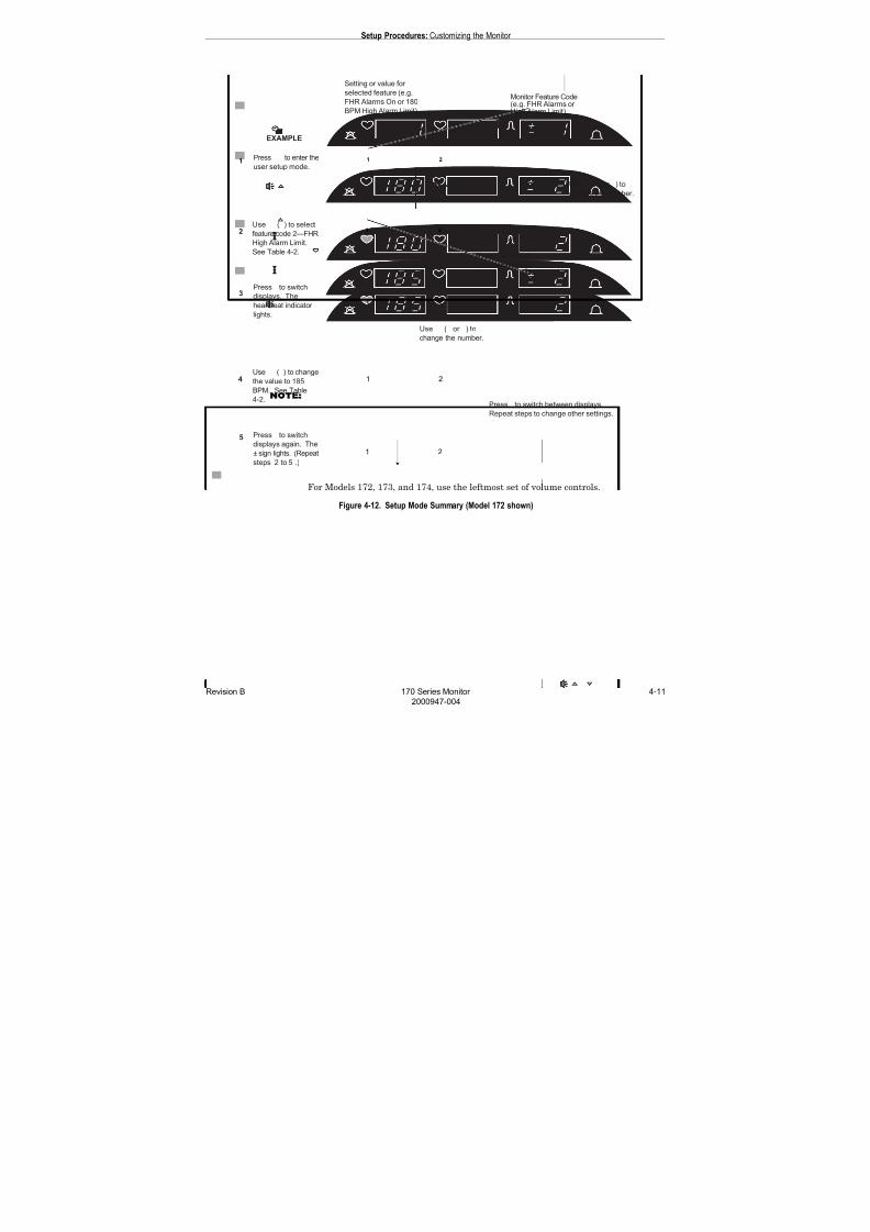
NOTE For Models 172, 173, and 174, use the leftmost set of volume controls.
Figure 4-12. Setup Mode Summary (Model 172 shown)
7/25/2019 Serv. Corometrics 170
http://slidepdf.com/reader/full/serv-corometrics-170 50/254
4-12 170 Series Monitor Revision B
2000947-004
Setup Procedures: Customizing the Monitor
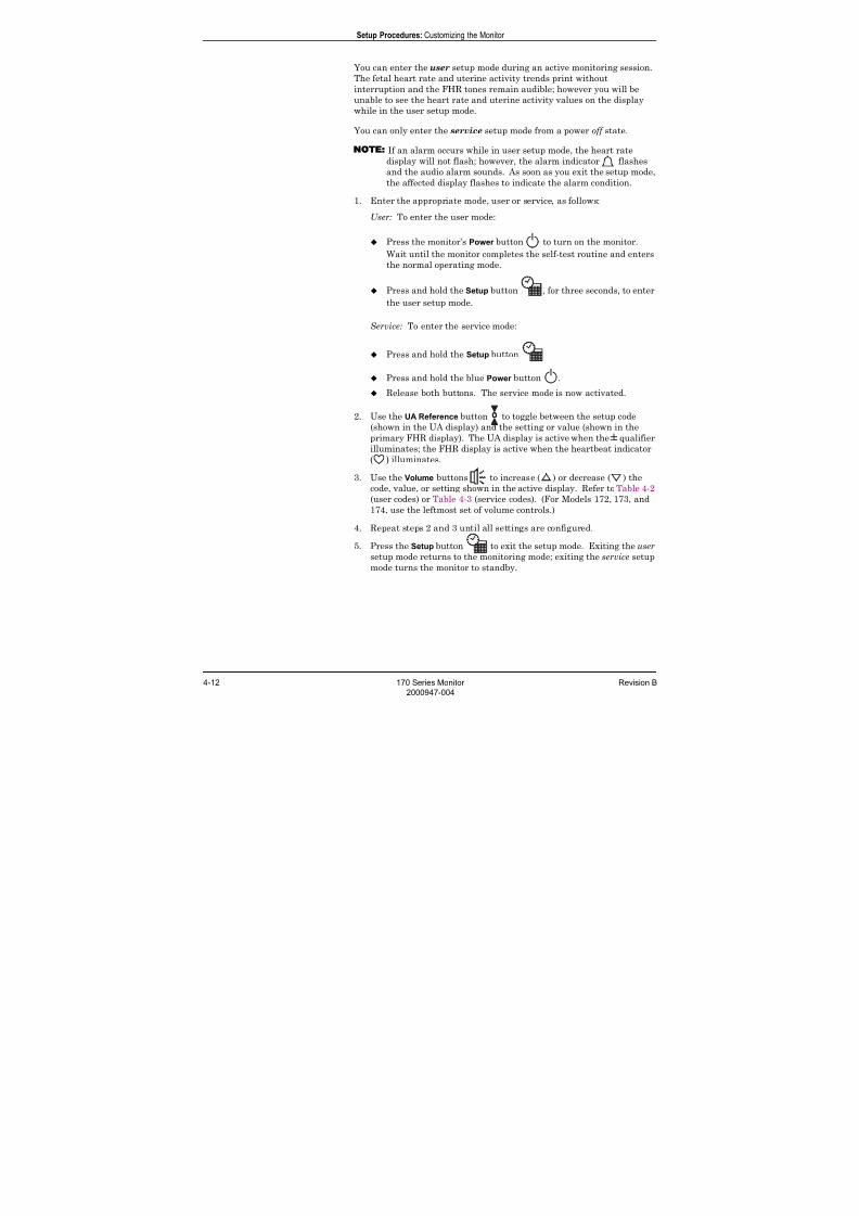
You can enter the user setup mode during an active monitoring session.
The fetal heart rate and uterine activity trends print without
interruption and the FHR tones remain audible; however you will be
unable to see the heart rate and uterine activity values on the display
while in the user setup mode.
You can only enter the service setup mode from a power off state.
NOTE
If an alarm occurs while in user setup mode, the heart rate
display will not flash; however, the alarm indicator flashes
and the audio alarm sounds. As soon as you exit the setup mode,
the affected display flashes to indicate the alarm condition.
1. Enter the appropriate mode, user or service, as follows:
User: To enter the user mode:
Press the monitor’s Power button to turn on the monitor.
Wait until the monitor completes the self-test routine and enters
the normal operating mode.
Press and hold the Setup button , for three seconds, to enter
the user setup mode.
Service: To enter the service mode:
Press and hold the Setup button
Press and hold the blue Power button .
Release both buttons. The service mode is now activated.
2. Use the UA Reference button to toggle between the setup code
(shown in the UA display) and the setting or value (shown in the
primary FHR display). The UA display is active when the ± qualifier
illuminates; the FHR display is active when the heartbeat indicator
( ) illuminates.
3. Use the Volume buttons to increase ( ) or decrease ( ) the
code, value, or setting shown in the active display. Refer to Table 4-2
(user codes) or Table 4-3 (service codes). (For Models 172, 173, and
174, use the leftmost set of volume controls.)
4. Repeat steps 2 and 3 until all settings are configured.
5. Press the Setup button to exit the setup mode. Exiting the usersetup mode returns to the monitoring mode; exiting the service setup
mode turns the monitor to standby.

7/25/2019 Serv. Corometrics 170
http://slidepdf.com/reader/full/serv-corometrics-170 51/254
Revision B 170 Series Monitor 4-13
2000947-004
Setup Procedures: Customizing the Monitor
NOTE If you press the Power button to exit the setup mode (user or
service) any changes you made will not be stored in memory.
NOTE You must exit by pressing the Setup button in order for
changes to take effect.
NOTE If an alarm is in progress when you exit the user setup mode,
any changes to an alarm setting do not take effect until the alarmcondition is resolved.
Table 4-2 lists the available settings for the user setup mode. Table 4-3
lists the available settings for the service setup mode. Table 4-4 provides
a summary of the factory default settings for both the user and service
setup options.
7/25/2019 Serv. Corometrics 170
http://slidepdf.com/reader/full/serv-corometrics-170 52/254
4-14 170 Series Monitor Revision B
2000947-004
Setup Procedures: Customizing the Monitor
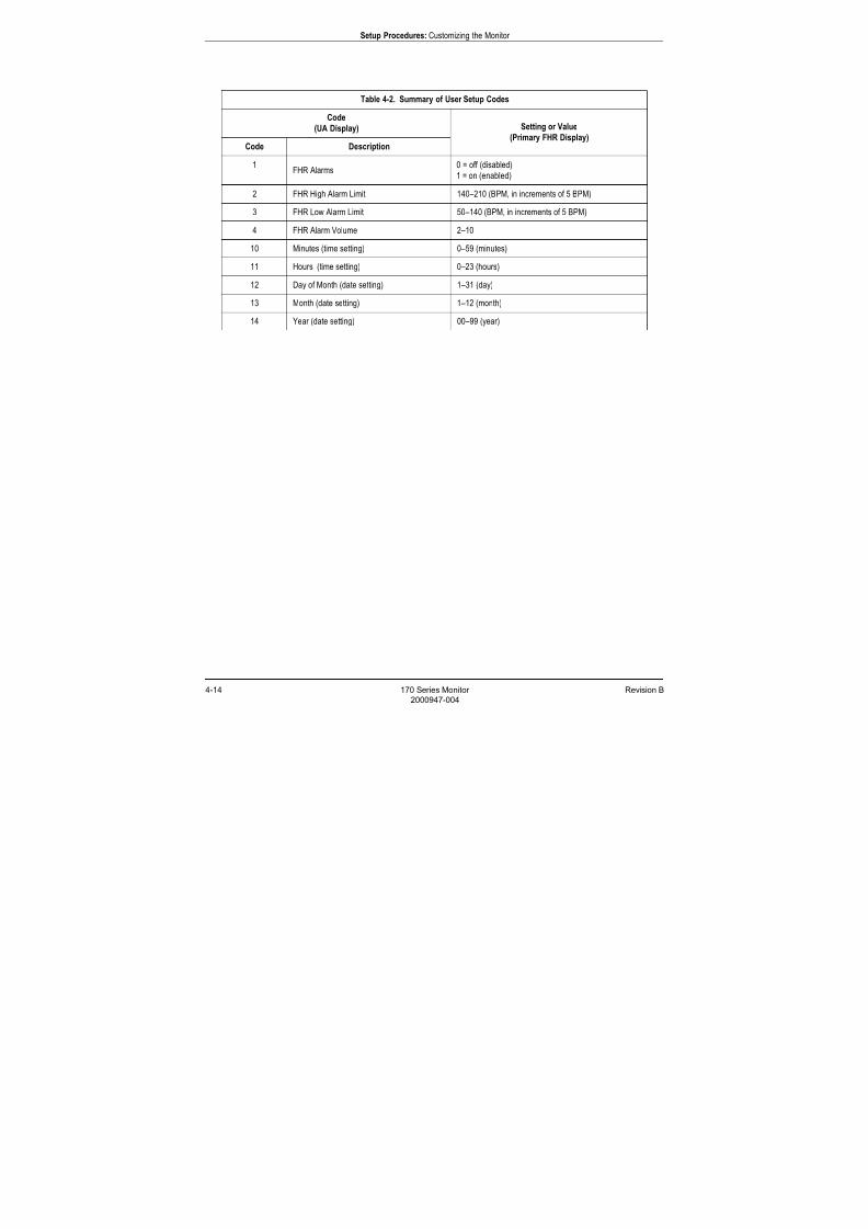
Table 4-2. Summary of User Setup Codes
Code
(UA Display) Setting or Value
(Primary FHR Display)Code Description
1FHR Alarms
0 = off (disabled)
1 = on (enabled)
2 FHR High Alarm Limit 140–210 (BPM, in increments of 5 BPM)
3 FHR Low Alarm Limit 50–140 (BPM, in increments of 5 BPM)
4 FHR Alarm Volume 2–10
10 Minutes (time setting) 0–59 (minutes)
11 Hours (time setting) 0–23 (hours)
12 Day of Month (date setting) 1–31 (day)
13 Month (date setting) 1–12 (month)
14 Year (date setting) 00–99 (year)
7/25/2019 Serv. Corometrics 170
http://slidepdf.com/reader/full/serv-corometrics-170 53/254
Revision B 170 Series Monitor 4-15
2000947-004
Setup Procedures: Customizing the Monitor
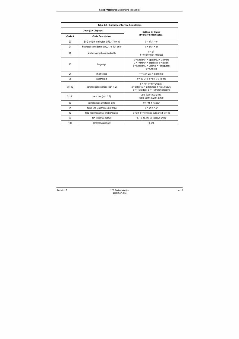
Table 4-3. Summary of Service Setup Codes
Code (UA Display)Setting Or Value
(Primary FHR Display)Code # Code Description
20 ECG artifact elimination (173, 174 only) 0 = off; 1 = on
21 heartbeat coincidence (172, 173, 174 only) 0 = off; 1 = on
22 fetal movement enable/disable0 = off
1 = on (if option installed)
23 language
0 = English; 1 = Spanish; 2 = German;
3 = French; 4 = Japanese; 5 = Italian;
6 = Swedish; 7 = Dutch; 8 = Portuguese;
9 = Chinese
24 chart speed 1= 1; 2 = 2; 3 = 3 (cm/min)
25 paper scale 0 = 30–240; 1 = 50–210 (BPM)
30, 40 communications mode (port 1, 2)
0 = HP; 1 = HP w/notes;
2 = ext BP; 3 = factory test; 4 = ext. FSpO2;
5 = 115 update; 6 = 115 transmit/receive
31, 41 baud rate (port 1, 2)300; 600; 1200; 2400;
4800; 9600; 19200; 38400
50 remote mark annotation style 0 = FM; 1 = arrow
51 future use (Japanese units only) 0 = off; 1 = on
52 fetal heart rate offset enable/disable 0 = off; 1 = 10 minute auto-revert; 2 = on
53 UA reference default 5, 10, 15, 20, 25 (relative units)
100 recorder alignment 0–255

7/25/2019 Serv. Corometrics 170
http://slidepdf.com/reader/full/serv-corometrics-170 54/254
4-16 170 Series Monitor Revision B
2000947-004
Setup Procedures: Customizing the Monitor
* = service setup mode
Table 4-4. Summary of Factory Defaults
Setup Option Factory Default Hospital/Clinic Setting
FHR Alarms on
FHR High Alarm Limit 160 BPM
FHR Low Alarm Limit 120 BPM
FHR Alarm Volume 5
Time/Date
Eastern Standard Time or Daylight-
Saving Time—whichever is
applicable
*ECG Artifact Elimination
(Models 173 and 174 only)off
*Heartbeat Coincidence(Models 172, 173, and 174 only)
off
*Fetal Movement Detection
(if purchased and installed)on
*Languageset according to shipping
destination
*Recorder SpeedUnited States: 3 cm/min
International: 1 cm/min
*Paper ScaleUnited States: 30–240 BPM
International: 50–210 BPM
*RS-232 Port 1
Communications ModeHP
*RS-232 Port 1
Baud Rate1200
*RS-232 Port 2
Communications Modeext. BP
*RS-232 Port 2
Baud Rate600
*Remote Mark Annotation on ( )
*HR Offset
(Models 172, 173, and 174 only)on with 10-minute auto-revert
*UA Reference 10 relative units

7/25/2019 Serv. Corometrics 170
http://slidepdf.com/reader/full/serv-corometrics-170 55/254
Revision B 170 Series Monitor 4-17
2000947-004
Setup Procedures: Customizing the Monitor
Printing a Summary of Configuration Settings
To print the software version number and a summary of configuration
settings on the strip chart paper:
NOTE You can only enter the service setup mode from a power off state.
1. Enter the service mode:
Press and hold the Setup button
Press and hold the blue Power button .
Release both buttons. The service mode is now activated.
2. Press the Record button . Figure 4-13 shows a sample printout.
Figure 4-13. Configuration Summary Printout
7/25/2019 Serv. Corometrics 170
http://slidepdf.com/reader/full/serv-corometrics-170 56/254
4-18 170 Series Monitor Revision B
2000947-004
Setup Procedures: Quick Reference Card
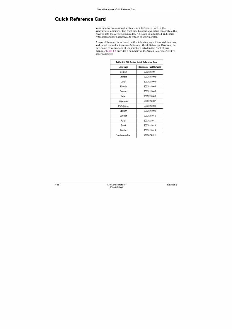
Quick Reference Card
Your monitor was shipped with a Quick Reference Card in the
appropriate language. The front side lists the user setup codes while the
reverse lists the service setup codes. The card is laminated and comes
with hook and loop adhesives to attach to your monitor.
A copy of this card is included on the following page if you wish to make
additional copies for training. Additional Quick Reference Cards can be
purchased by calling one of the numbers listed in the front of this
manual. Table 4-5 provides a summary of the Quick Reference Card re-
order numbers:
Table 4-5. 170 Series Quick Reference Card
Language Document Part Number
English 2003024-001
Chinese 2003024-002
Dutch 2003024-003
French 2003024-004
German 2003024-005
Italian 2003024-006
Japanese 2003024-007
Portuguese 2003024-008
Spanish 2003024-009
Swedish 2003024-010
Polish 2003024-011
Greek 2003024-013
Russian 2003024-014
Czechoslovakian 2003024-015

7/25/2019 Serv. Corometrics 170
http://slidepdf.com/reader/full/serv-corometrics-170 57/254

7/25/2019 Serv. Corometrics 170
http://slidepdf.com/reader/full/serv-corometrics-170 58/254
4-20 170 Series Monitor Revision B
2000947-004
Setup Procedures: Flasher Software Utility Upgrade
Flasher Software Utility Upgrade
The Corometrics Flasher is a software utility program which uses one of
the monitor’s RS-232 serial ports to upgrade to a newer software release;
or to install a purchased option such as fetal movement detection. Each
Flasher disk contains the software upgrade for one-time use only. (Inother words, you need an individual Flasher disk for each monitor being
upgraded.) Table 4-6 lists the Flasher kits available for the 170 Series.
Table 4-6. Flasher Kits
Kit Description Catalog Number
Fetal Movement Detection
Feature Addition1700AAO
Software Upgrade to Version 3.2xwhich includes the following
features:
Heartbeat coincidence
Portuguese/Chinese languages
(1701BAO only)
Communications interface to
external FSpO2 monitors
Communications support of 115
Update and 115 Transmit/
Receive protocols
1701AAO (English language units)
1701BAO (non-English language units)
7/25/2019 Serv. Corometrics 170
http://slidepdf.com/reader/full/serv-corometrics-170 59/254
Revision B 170 Series Monitor 5-1
2000947-004
Chapter 5
Theory of Operation 5This section of the manual contains the electronic theory of operation for
the 170 Series Monitor. When possible, references are made to the
appropriate schematic contained in “Chapter 11, Parts Lists” of this
manual
Throughout this chapter, signal names ending with an asterisk (*) are
active low.
This chapter contains the following information:
Functional Overview . . . . . . . . . . . . . . . . . . . . . . . . . . . . . . . 5-2
Main Board Theory of Operation. . . . . . . . . . . . . . . . . . . . . 5-17
FECG/IUP Board Theory of Operation . . . . . . . . . . . . . . . . 5-36

7/25/2019 Serv. Corometrics 170
http://slidepdf.com/reader/full/serv-corometrics-170 60/254
5-2 170 Series Monitor Revision B
2000947-004
Theory of Operation: Functional Overview
Functional Overview
For all 170 Series Monitors, the Main Board controls the majority of the
170 Series functionality including:
antepartum (US, TOCO) front ends and connector(s) uterine activity front end and connector
seven-segment displays
user-interface buttons
peripheral device communications
processing
For Models 173 and 174, a separate FECG/IUP Board controls:
intrapartum front ends
isolation for analog signals
Figure 5-1 provides an overview of the system architecture. Table 5-1
through Table 5-17 provide pinouts for each of the external connectors
and the internal main board harness connectors. Figure 5-2 through
Figure 5-9 provide illustrations of the front and rear panel connectors.
Figure 5-1. Overview of System Architecture

7/25/2019 Serv. Corometrics 170
http://slidepdf.com/reader/full/serv-corometrics-170 61/254
Revision B 170 Series Monitor 5-3
2000947-004
Theory of Operation: Functional Overview
Figure 5-2. Main Power Connector
Table 5-1. Main Power Connector
Pin Number Description
1 +12 Vdc Input
2 Negative Input
3 Shield
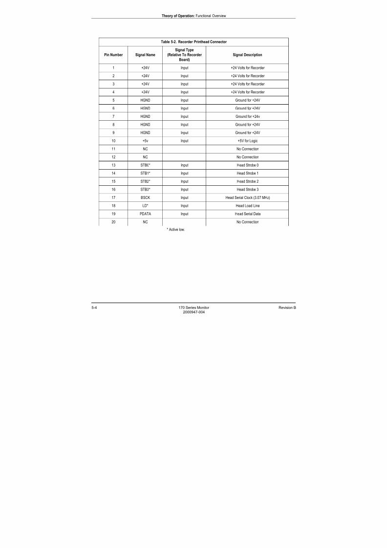
7/25/2019 Serv. Corometrics 170
http://slidepdf.com/reader/full/serv-corometrics-170 62/254
5-4 170 Series Monitor Revision B
2000947-004
Theory of Operation: Functional Overview
* Active low.
Table 5-2. Recorder Printhead Connector
Pin Number Signal Name
Signal Type
(Relative To Recorder
Board)
Signal Description
1 +24V Input +24 Volts for Recorder
2 +24V Input +24 Volts for Recorder
3 +24V Input +24 Volts for Recorder
4 +24V Input +24 Volts for Recorder
5 HGND Input Ground for +24V
6 HGND Input Ground for +24V
7 HGND Input Ground for +24v
8 HGND Input Ground for +24V
9 HGND Input Ground for +24V
10 +5v Input +5V for Logic
11 NC No Connection
12 NC No Connection
13 STB0* Input Head Strobe 0
14 STB1* Input Head Strobe 1
15 STB2* Input Head Strobe 2
16 STB3* Input Head Strobe 3
17 BSCK Input Head Serial Clock (3.07 MHz)
18 LD* Input Head Load Line
19 PDATA Input Head Serial Data
20 NC No Connection

7/25/2019 Serv. Corometrics 170
http://slidepdf.com/reader/full/serv-corometrics-170 63/254
Revision B 170 Series Monitor 5-5
2000947-004
Theory of Operation: Functional Overview
Table 5-3. Recorder Motor Connector
Pin Number Signal Name
Signal Type
(Relative to
Main board)
Signal Description
1 NC No Connection
2 P3 Output Motor Phase 3
3 P4 Output Motor Phase 4
4 +5VM Output +5 Volts for Motor
5 NC No Connection
6 P2 Output Motor Phase 2
7 P1 Output Motor Phase 1
8 +5VM Output +5 Volts for Motor
Table 5-4. Recorder Sensor Connector
Pin Number Signal Name
Signal Type
(Relative to
Main board)
Signal Description
1 NC No Connection
2 MISCOL Input Paper Misload Sensor Collector
3 MISLED Output Paper Misload Sensor LED Voltage
4 GND Output Ground for Sensor
5 NC No Connection
6 OUTCOL Input Paper Out Sensor Collector
7 OUTLED Output Paper Out Sensor LED Voltage
8 GND Output Ground for Sensor
9 DOOR Input Door Switch Input
10 GND Output Ground for Door Switch
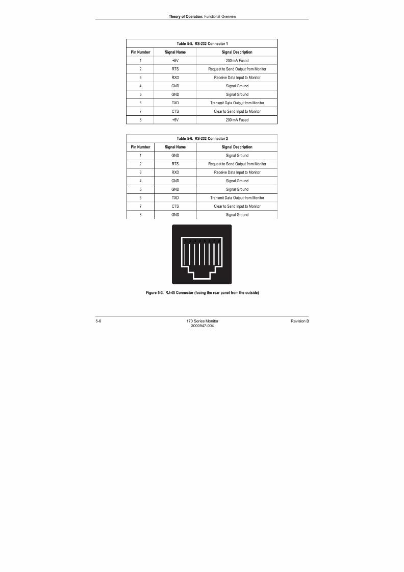
7/25/2019 Serv. Corometrics 170
http://slidepdf.com/reader/full/serv-corometrics-170 64/254
5-6 170 Series Monitor Revision B
2000947-004
Theory of Operation: Functional Overview
Figure 5-3. RJ-45 Connector (facing the rear panel from the outside)
Table 5-5. RS-232 Connector 1
Pin Number Signal Name Signal Description
1 +5V 200 mA Fused
2 RTS Request to Send Output from Monitor
3 RXD Receive Data Input to Monitor
4 GND Signal Ground
5 GND Signal Ground
6 TXD Transmit Data Output from Monitor
7 CTS Clear to Send Input to Monitor
8 +5V 200 mA Fused
Table 5-6. RS-232 Connector 2
Pin Number Signal Name Signal Description
1 GND Signal Ground
2 RTS Request to Send Output from Monitor
3 RXD Receive Data Input to Monitor
4 GND Signal Ground
5 GND Signal Ground
6 TXD Transmit Data Output from Monitor
7 CTS Clear to Send Input to Monitor
8 GND Signal Ground
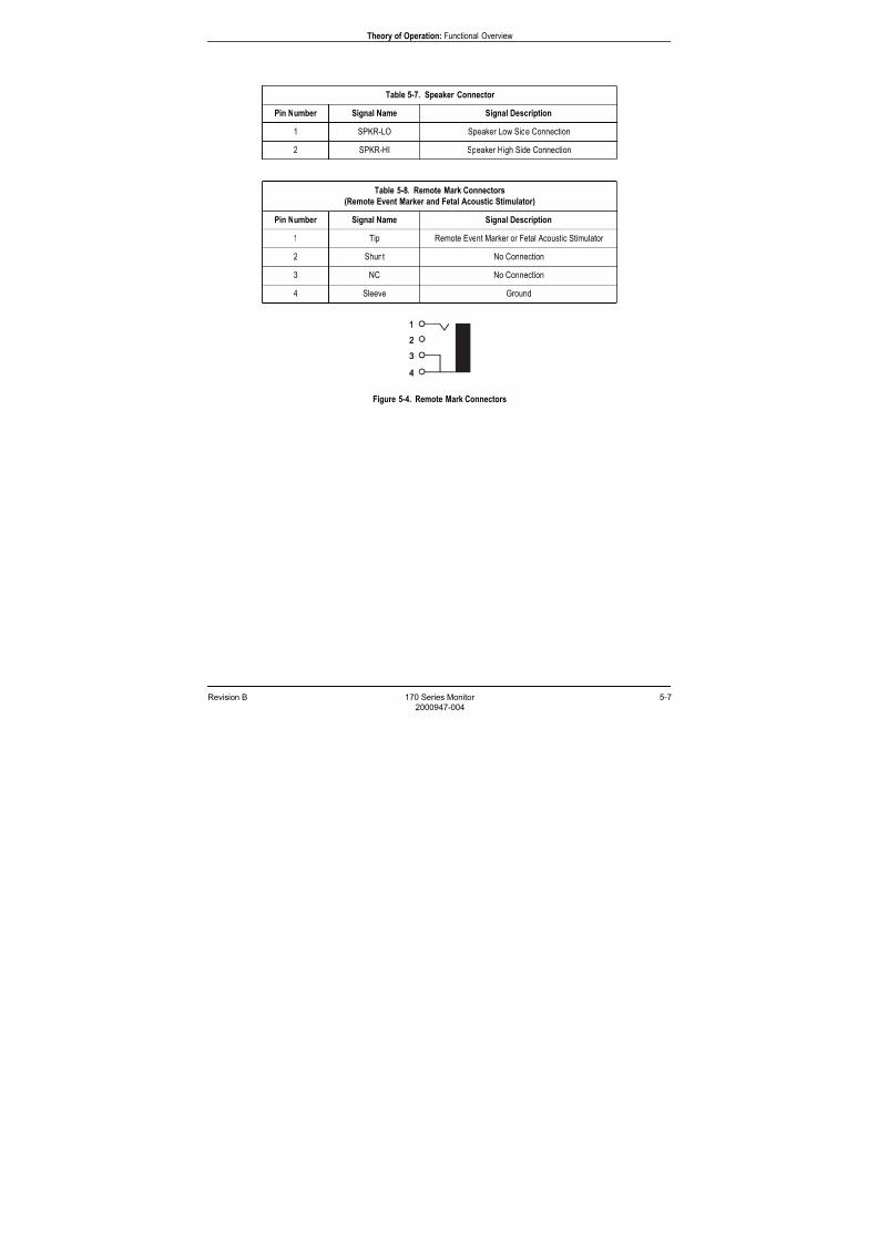
7/25/2019 Serv. Corometrics 170
http://slidepdf.com/reader/full/serv-corometrics-170 65/254
Revision B 170 Series Monitor 5-7
2000947-004
Theory of Operation: Functional Overview
Figure 5-4. Remote Mark Connectors
Table 5-7. Speaker Connector
Pin Number Signal Name Signal Description
1 SPKR-LO Speaker Low Side Connection
2 SPKR-HI Speaker High Side Connection
Table 5-8. Remote Mark Connectors
(Remote Event Marker and Fetal Acoustic Stimulator)
Pin Number Signal Name Signal Description
1 Tip Remote Event Marker or Fetal Acoustic Stimulator
2 Shunt No Connection
3 NC No Connection
4 Sleeve Ground
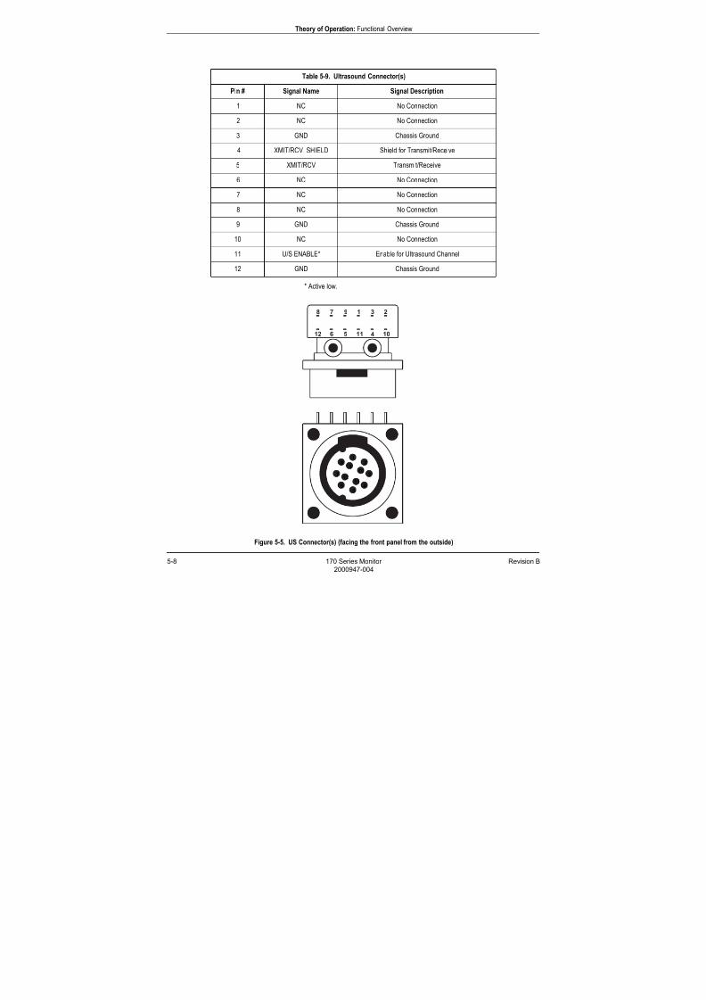
7/25/2019 Serv. Corometrics 170
http://slidepdf.com/reader/full/serv-corometrics-170 66/254
5-8 170 Series Monitor Revision B
2000947-004
Theory of Operation: Functional Overview
* Active low.
Figure 5-5. US Connector(s) (facing the front panel from the outside)
Table 5-9. Ultrasound Connector(s)
Pin # Signal Name Signal Description
1 NC No Connection
2 NC No Connection
3 GND Chassis Ground
4 XMIT/RCV SHIELD Shield for Transmit/Receive
5 XMIT/RCV Transmit/Receive
6 NC No Connection
7 NC No Connection
8 NC No Connection
9 GND Chassis Ground
10 NC No Connection
11 U/S ENABLE* Enable for Ultrasound Channel
12 GND Chassis Ground
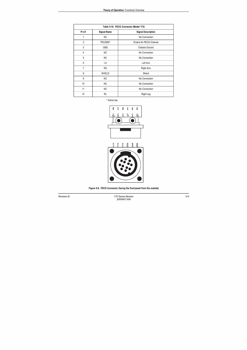
7/25/2019 Serv. Corometrics 170
http://slidepdf.com/reader/full/serv-corometrics-170 67/254
Revision B 170 Series Monitor 5-9
2000947-004
Theory of Operation: Functional Overview
* Active low.
Figure 5-6. FECG Connector (facing the front panel from the outside)
Table 5-10. FECG Connector (Model 173)
Pin # Signal Name Signal Description
1 NC No Connection
2 FECGEN* Enable for FECG Channel
3 GND Chassis Ground
4 NC No Connection
5 NC No Connection
6 LA Left Arm
7 RA Right Arm
8 SHIELD Shield
9 NC No Connection
10 NC No Connection
11 NC No Connection
12 RL Right Leg
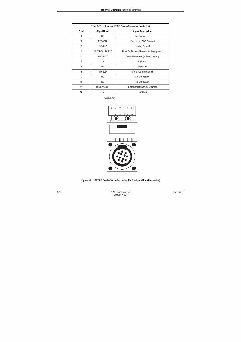
7/25/2019 Serv. Corometrics 170
http://slidepdf.com/reader/full/serv-corometrics-170 68/254
5-10 170 Series Monitor Revision B
2000947-004
Theory of Operation: Functional Overview
* Active low.
Figure 5-7. US/FECG Combi-Connector (facing the front panel from the outside)
Table 5-11. Ultrasound/FECG Combi-Connector (Model 174)
Pin # Signal Name Signal Description
1 NC No Connection
2 FECGEN* Enable for FECG Channel
3 ISOGND Isolated Ground
4 XMIT/RCV SHIELD Shield for Transmit/Receive (isolated ground)
5 XMIT/RCV Transmit/Receive (isolated ground)
6 LA Left Arm
7 RA Right Arm
8 SHIELD Shield (isolated ground)
9 NC No Connection
10 NC No Connection
11 U/S ENABLE* Enable for Ultrasound Channel
12 RL Right Leg
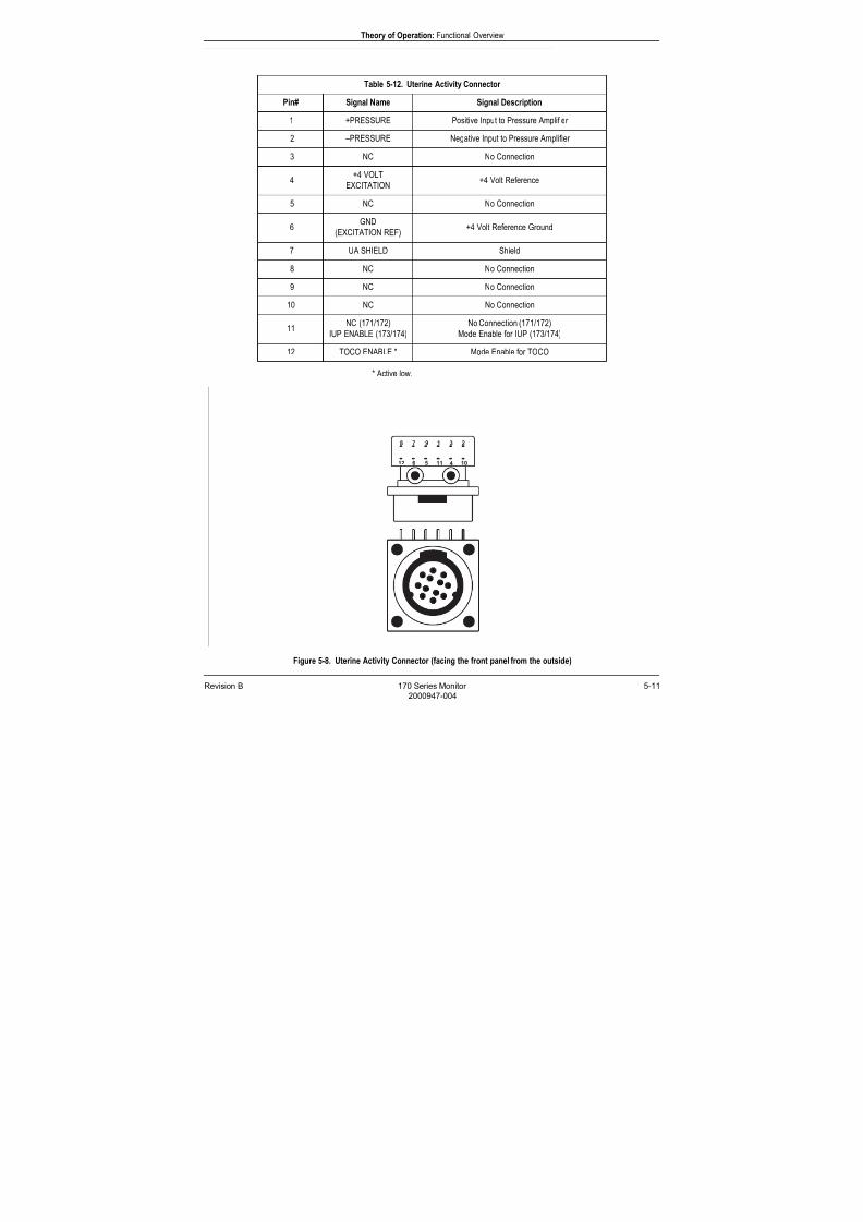
7/25/2019 Serv. Corometrics 170
http://slidepdf.com/reader/full/serv-corometrics-170 69/254
Revision B 170 Series Monitor 5-11
2000947-004
Theory of Operation: Functional Overview
* Active low.
Figure 5-8. Uterine Activity Connector (facing the front panel from the outside)
Table 5-12. Uterine Activity Connector
Pin# Signal Name Signal Description
1 +PRESSURE Positive Input to Pressure Amplifier
2 –PRESSURE Negative Input to Pressure Amplifier
3 NC No Connection
4+4 VOLT
EXCITATION+4 Volt Reference
5 NC No Connection
6GND
(EXCITATION REF)+4 Volt Reference Ground
7 UA SHIELD Shield
8 NC No Connection
9 NC No Connection
10 NC No Connection
11NC (171/172)
IUP ENABLE (173/174)
No Connection (171/172)
Mode Enable for IUP (173/174)
12 TOCO ENABLE * Mode Enable for TOCO
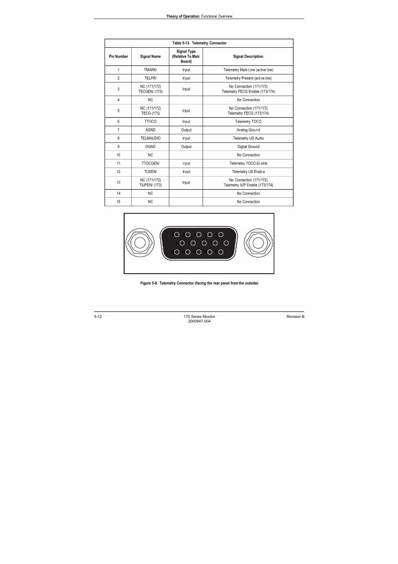
7/25/2019 Serv. Corometrics 170
http://slidepdf.com/reader/full/serv-corometrics-170 70/254
5-12 170 Series Monitor Revision B
2000947-004
Theory of Operation: Functional Overview
Figure 5-9. Telemetry Connector (facing the rear panel from the outside)
Table 5-13. Telemetry Connector
Pin Number Signal Name
Signal Type
(Relative To Main
Board)
Signal Description
1 TMARK/ Input Telemetry Mark Line (active low)
2 TELPR/ Input Telemetry Present (active low)
3NC (171/172)
TECGEN/ (173)Input
No Connection (171/172)
Telemetry FECG Enable (173/174)
4 NC No Connection
5NC (171/172)
TECG (173)Input
No Connection (171/172)
Telemetry FECG (173/174)
6 TTOCO Input Telemetry TOCO
7 AGND Output Analog Ground
8 TELMAUDIO Input Telemetry US Audio
9 DGND Output Digital Ground
10 NC No Connection
11 TTOCOEN/ Input Telemetry TOCO Enable
12 TUSEN/ Input Telemetry US Enable
13NC (171/172)
TIUPEN/ (173)Input
No Connection (171/172)
Telemetry IUP Enable (173/174)
14 NC No Connection
15 NC No Connection
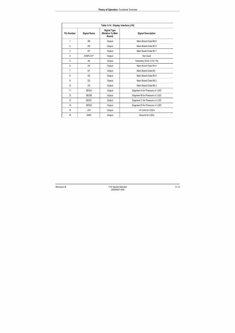
7/25/2019 Serv. Corometrics 170
http://slidepdf.com/reader/full/serv-corometrics-170 71/254
Revision B 170 Series Monitor 5-13
2000947-004
Theory of Operation: Functional Overview
Table 5-14. Display Interface (J18)
Pin Number Signal Name
Signal Type
(Relative To Main
Board)
Signal Description
1 D6 Output Main Board Data Bit 6
2 D5 Output Main Board Data Bit 5
3 D7 Output Main Board Data Bit 7
4 DISPLCS* Output Not Used
5 A0 Output Telemetry ECG (173/174)
6 D4 Output Main Board Data Bit 4
7 D1 Output Main Board Data Bit 1
8 D0 Output Main Board Data Bit 0
9 D2 Output Main Board Data Bit 2
10 D3 Output Main Board Data Bit 3
11 SEGA Output Segment A for Pressure ±1 LED
12 SEGB Output Segment B for Pressure ±1 LED
13 SEGC Output Segment C for Pressure ±1 LED
14 SEGD Output Segment D for Pressure ±1 LED
15 +5V Output +5 Volts for LEDs
16 GND Output Ground for LEDs

7/25/2019 Serv. Corometrics 170
http://slidepdf.com/reader/full/serv-corometrics-170 72/254
5-14 170 Series Monitor Revision B
2000947-004
Theory of Operation: Functional Overview
* Active low.
Table 5-15. Membrane Switch Panel Interface (J19)
Pin Number Signal Name
Signal Type
(Relative To Main
Board)
Signal Description
1 UAREF* Input UA Ref Switch Input
2 PWRANODE Output Power Indicator LED Anode
3 REC* Input Recorder On Switch Input
4 NC Output No Connection
5 MARK* Input Mark Switch Input
7 PADV* Input Paper Advance Switch Input
6 GND Output Ground
8 RECANODE Output Recorder on LED Anode
9 VOLDN* Input Volume Down Channel 1 Switch Input
10 CANCEL Input Alarm Cancel Switch Input
11 VOLUP* Input Volume Up Channel 1 Switch Input
12 VOLDN2* Input Volume Down Channel 2 Switch Input
13 PWRSWITCH Input Power Switch Input
14 VOLUP2* Input Volume Up Channel 2 Switch Input
15 GND Output Ground for LEDS and Switches
16 MENU Input Menu Switch Input
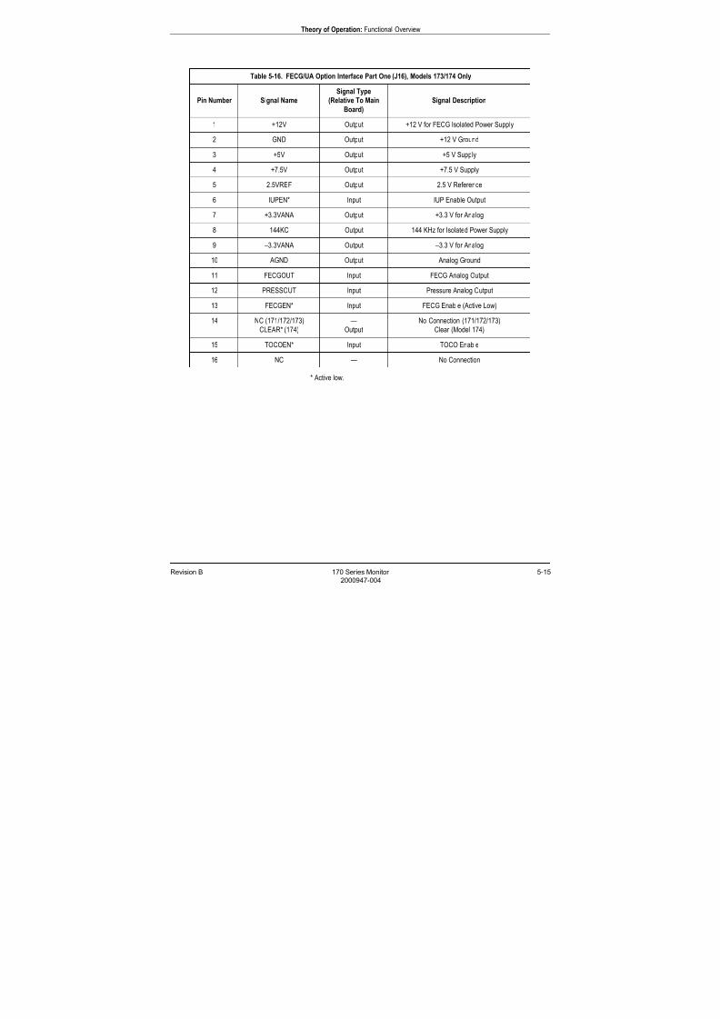
7/25/2019 Serv. Corometrics 170
http://slidepdf.com/reader/full/serv-corometrics-170 73/254
Revision B 170 Series Monitor 5-15
2000947-004
Theory of Operation: Functional Overview
* Active low.
Table 5-16. FECG/UA Option Interface Part One (J16), Models 173/174 Only
Pin Number Signal Name
Signal Type
(Relative To Main
Board)
Signal Description
1 +12V Output +12 V for FECG Isolated Power Supply
2 GND Output +12 V Ground
3 +5V Output +5 V Supply
4 +7.5V Output +7.5 V Supply
5 2.5VREF Output 2.5 V Reference
6 IUPEN* Input IUP Enable Output
7 +3.3VANA Output +3.3 V for Analog
8 144KC Output 144 KHz for Isolated Power Supply
9 –3.3VANA Output –3.3 V for Analog
10 AGND Output Analog Ground
11 FECGOUT Input FECG Analog Output
12 PRESSOUT Input Pressure Analog Output
13 FECGEN* Input FECG Enable (Active Low)
14 NC (171/172/173)
CLEAR* (174)
—
Output
No Connection (171/172/173)
Clear (Model 174)
15 TOCOEN* Input TOCO Enable
16 NC — No Connection
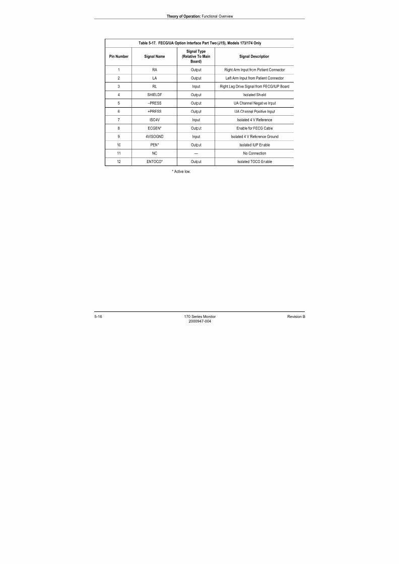
7/25/2019 Serv. Corometrics 170
http://slidepdf.com/reader/full/serv-corometrics-170 74/254
5-16 170 Series Monitor Revision B
2000947-004
Theory of Operation: Functional Overview
* Active low.
Table 5-17. FECG/UA Option Interface Part Two (J15), Models 173/174 Only
Pin Number Signal Name
Signal Type
(Relative To Main
Board)
Signal Description
1 RA Output Right Arm Input from Patient Connector
2 LA Output Left Arm Input from Patient Connector
3 RL Input Right Leg Drive Signal from FECG/IUP Board
4 SHIELDF Output Isolated Shield
5 –PRESS Output UA Channel Negative Input
6 +PRESS Output UA Channel Positive Input
7 ISO4V Input Isolated 4 V Reference
8 ECGEN* Output Enable for FECG Cable
9 4VISOGND Input Isolated 4 V Reference Ground
10 PEN* Output Isolated IUP Enable
11 NC — No Connection
12 ENTOCO* Output Isolated TOCO Enable

7/25/2019 Serv. Corometrics 170
http://slidepdf.com/reader/full/serv-corometrics-170 75/254
Revision B 170 Series Monitor 5-17
2000947-004
Theory of Operation: Main Board Theory of Operation
Main Board Theory of Operation
Figure 5-10 provides a block diagram of the Main Board in the 170 Series
Monitor. The board number varies according to the particular model in
the series as summarized in Table 5-18.
Table 5-18. Main Board Variations
170 Series Model Main Board FRU Number Ultrasound Channels FECG/IUP Board Mount
Model 171 2000244 Single No
Model 172 15269 Dual No
Model 173 2000324 Single Yes
Model 174 2000952 Dual Yes
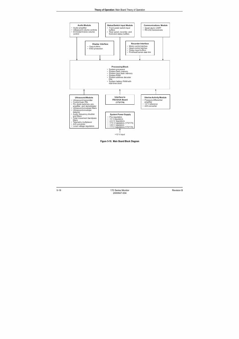
7/25/2019 Serv. Corometrics 170
http://slidepdf.com/reader/full/serv-corometrics-170 76/254
5-18 170 Series Monitor Revision B
2000947-004
Theory of Operation: Main Board Theory of Operation
Figure 5-10. Main Board Block Diagram
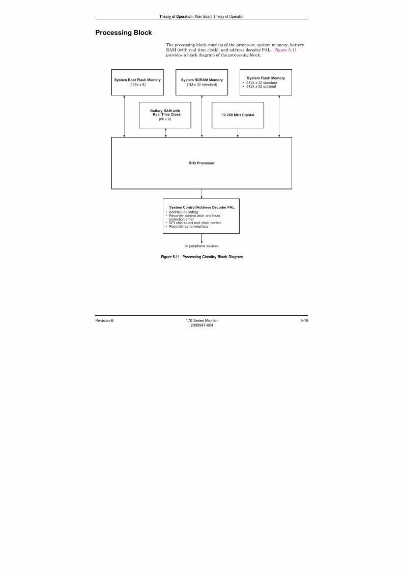
7/25/2019 Serv. Corometrics 170
http://slidepdf.com/reader/full/serv-corometrics-170 77/254
Revision B 170 Series Monitor 5-19
2000947-004
Theory of Operation: Main Board Theory of Operation
Processing Block
The processing block consists of the processor, system memory, battery
RAM (with real time clock), and address decoder PAL. Figure 5-11
provides a block diagram of the processing block.
Figure 5-11. Processing Circuitry Block Diagram
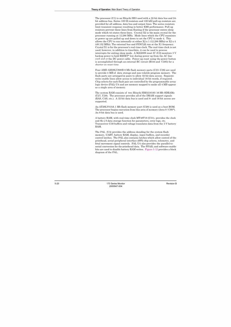
7/25/2019 Serv. Corometrics 170
http://slidepdf.com/reader/full/serv-corometrics-170 78/254
5-20 170 Series Monitor Revision B
2000947-004
Theory of Operation: Main Board Theory of Operation
The processor (U1) is an Hitachi SH3 used with a 32-bit data bus and 24-
bit address bus. Series 100 Ω resistors and 100 kΩ pull-up resistors are
provided for all address, data bus and output lines. The series resistors
limit transient response resulting in better EMI performance. Pull-up
resistors prevent these lines from floating if the processor enters sleep
mode which tri-states these lines. Crystal X2 is the main crystal for the
processor running at 12.288 MHz. Mode lines which the CPU examines
at power up are pulled up and down to set the CPU to mode 4. This
allows the CPU to run internally at either X2 x 1 (12.288 MHz) or X2 x 4
(49.152 MHz). The external bus and SYSCLK run at the X1 frequency.
Crystal X1 is for the processor’s real-time clock. The real-time clock is not
used; however, in addition to time/date, it can be used to process
interrupts for exiting sleep mode. A MAX809 reset IC (U2) monitors 3 V
backup power to hold RESET* low during power up from the AC line
cord and or the DC power cable. Power-up reset using the power button
is accomplished through an external RC circuit (R544 and C285) for a
shorter on reset time.
Four AMD AM29LV800B 8 Mb flash memory parts (U23–U26) are used
to provide 4 MB of data storage and non-volatile program memory. Theflash parts are arranged in pairs to allow 32-bit data access. Separate
write enable lines allow access to individual 16-bit words, if required.
Chip selects for each flash pair are controlled by the programmable array
logic device (PAL) U4 and are memory mapped to make all 4 MB appear
as a single area of memory.
The system RAM consists of two Hitachi HM5216165 16-Mb SDRAMs
(U27, U28). The processor provides all of the DRAM support signals
(RAS, CAS, etc.). A 32-bit data bus is used and 8- and 16-bit access are
supported.
An AT29LV010A 1 Mb flash memory part (U29) is used as a boot ROM.
The processor begins execution from this area of memory (Area 0 / CS0*). An 8-bit data bus is used.
A battery RAM, with real-time clock MT48T18 (U31), provides the clock
and 8k x 8 data storage function for parameters, error logs, etc.
Transceiver U30 buffers and voltage translates data from the 5 V battery
RAM.
The PAL (U4) provides the address decoding for the system flash
memory, UART, battery RAM, display, input buffers, and recorder
control latches. The PAL also contains latches which allow control of the
printhead, serial peripheral interface (SPI) chip selects, telemetry, and
fetal movement signal controls. PAL U4 also provides the parallel-to-
serial conversion for the printhead data. The PFAIL and software enable
bits are used to disable battery RAM writes. Figure 5-12 provides a block
diagram of the PAL.

7/25/2019 Serv. Corometrics 170
http://slidepdf.com/reader/full/serv-corometrics-170 79/254
Revision B 170 Series Monitor 5-21
2000947-004
Theory of Operation: Main Board Theory of Operation
Figure 5-12. PAL Block Diagram
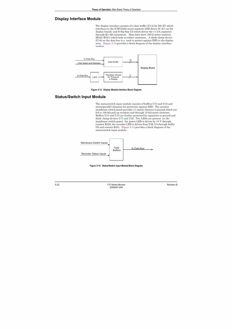
7/25/2019 Serv. Corometrics 170
http://slidepdf.com/reader/full/serv-corometrics-170 80/254
5-22 170 Series Monitor Revision B
2000947-004
Theory of Operation: Main Board Theory of Operation
Display Interface Module
The display interface consists of a data buffer (U14) for D0–D7 which
interfaces to the ICM7228A seven-segment LED driver IC (U1 on the
display board), and D flip-flop U3 which drives the ±1 UA segments
through Q1–Q4 transistors. Data lines have 100 Ω series resistors
(R524–R531) which help to reduce emissions. A diode clamp device(U18) on the data bus is a used to protect against ESD to the display
area. Figure 5-13 provides a block diagram of the display interface
module.
Figure 5-13. Display Module Interface Block Diagram
Status/Switch Input Module
The status/switch input module consists of buffers U15 and U16 and
series/parallel elements for protection against ESD. The monitor
membrane switch panel provides 11 switch closures to ground which are
fed to 100 kΩ pull up resistors and through 10 kΩ series elements.
Buffers U14 and U15 are further protected by capacitors to ground and
diode clamp devices U17 and U22. Two LEDs are present on the
membrane switch panel: the power LED is driven by +5 V through
resistor R350; the recorder LED is driven from PAL U4 through buffer
U6 and resistor R351. Figure 5-14 provides a block diagram of the
status/switch input module.
Figure 5-14. Status/Switch Input Module Block Diagram
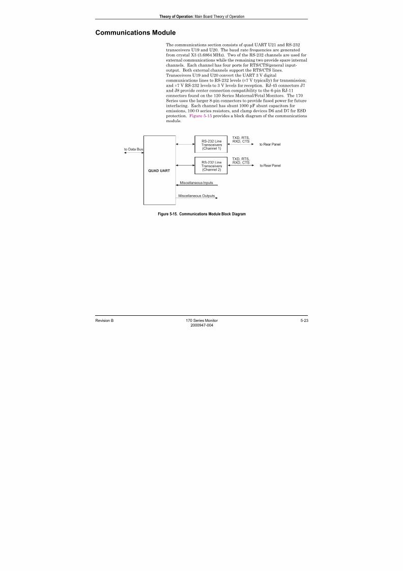
7/25/2019 Serv. Corometrics 170
http://slidepdf.com/reader/full/serv-corometrics-170 81/254
Revision B 170 Series Monitor 5-23
2000947-004
Theory of Operation: Main Board Theory of Operation
Communications Module
The communications section consists of quad UART U21 and RS-232
transceivers U19 and U20. The baud rate frequencies are generated
from crystal X3 (3.6864 MHz). Two of the RS-232 channels are used for
external communications while the remaining two provide spare internal
channels. Each channel has four ports for RTS/CTS/general input-output. Both external channels support the RTS/CTS lines.
Transceivers U19 and U20 convert the UART 3 V digital
communications lines to RS-232 levels (±7 V typically) for transmission;
and ±7 V RS-232 levels to 3 V levels for reception. RJ-45 connectors J7
and J8 provide center connection compatibility to the 6-pin RJ-11
connectors found on the 120 Series Maternal/Fetal Monitors. The 170
Series uses the larger 8-pin connectors to provide fused power for future
interfacing. Each channel has shunt 1000 pF shunt capacitors for
emissions, 100 Ω series resistors, and clamp devices D6 and D7 for ESD
protection. Figure 5-15 provides a block diagram of the communications
module.
Figure 5-15. Communications Module Block Diagram
7/25/2019 Serv. Corometrics 170
http://slidepdf.com/reader/full/serv-corometrics-170 82/254
5-24 170 Series Monitor Revision B
2000947-004
Theory of Operation: Main Board Theory of Operation
Recorder Interface Module
The recorder interface consists of motor control, paper status logic, and
printhead control logic. The motor control consists of latch U3, buffer
U6, and FET transistors Q5–Q8. The four phase signals are generated
by the processor using U3. These phases are translated to 5 V and
buffered by U6 to drive the FETs which in turn drive the unipolar motor.Clamp diodes are used to limit the inductive spike generated when the
switches open. The paper status logic consists of paper out and paper
misload optical sensor interface circuitry as well as a door switch
interface. The paper status logic consists of dual digital potentiometer
U9, resistors R216 and R217 for LED drive to the paper out sensor, and
R219 and R220 for LED drive to the paper misload sensor. The digital
potentiometer connects to the collector of the sensor transistor and
becomes the variable pull-up. These signals (MISCOIL and OUTCOIL)
are further processed by the analog-to-digital converter to determine the
correct threshold for the two sensors. Clamp device U8 is used for ESD
protection. The door switch input is a switch closure to ground and is
read by the processor through buffer U15. The printhead interface
consists of PAL U4 which contains the printhead control latch, head
protection circuitry, and printhead shift register. The printhead control
latch contains the four strobes for the printhead sections, the printhead
load line, and the printhead power supply enable line. The printhead
protection timer consists of a four-bit counter which uses a 2 kHz clock
[Usmode, U4 (pin 35)] to count off six clocks. The counter is enabled
when any one of the four processor-latched strobes is active. After six
counts of any active strobe (3 ms), the counter disables all four output
strobes and turns off the +24 V head supply. The circuit resets when the
processor-latched strobes return to an inactive state. The power fail
control line input U4 (pin 76) is also a form of protection which turns off
all strobes and the power supply when the +12 V drops to about 10 V.
The printhead shift register consists of an 8-bit shift register whichclocks out D7 first and clock counters which allow eight clocks to be
output for every processor write to the register. The clock counter also
provides a done status bit (BUSY*) which goes high after all eight bits
are shifted out. This status bit is read through the UART spare port line
U21 (pin 28).
Figure 5-16 provides a block diagram of the recorder interface.

7/25/2019 Serv. Corometrics 170
http://slidepdf.com/reader/full/serv-corometrics-170 83/254
Revision B 170 Series Monitor 5-25
2000947-004
Theory of Operation: Main Board Theory of Operation
Figure 5-16. Recorder Interface Block Diagram
7/25/2019 Serv. Corometrics 170
http://slidepdf.com/reader/full/serv-corometrics-170 84/254
5-26 170 Series Monitor Revision B
2000947-004
Theory of Operation: Main Board Theory of Operation
Ultrasound Module
Model 171 and Model 173 Monitors contain a single ultrasound
channel board. Model 172 and Model 174 Monitors contain a dual
ultrasound channel board. The theory contained in this section
references the dual ultrasound board but is applicable to the single
ultrasound board as well.
OverviewThe ultrasound circuitry is a dual channel pulsed Doppler system
with Channel 1 and Channel 2. Each channel generates a 1.151 MHz
(center frequency) pulsed carrier signal. This signal carrier causes
the crystals in the transducer to emit ultrasonic waves. When these
sound waves enter the maternal abdomen, they create echoes when
encountering an interface between tissues of differing acoustic
impedance. If the interface is moving either toward or away from the
ultrasound transducer, the frequency of the reflected sound differs
from the frequency sent from the transducer.
Isolation Transformer Model 174 Monitors have an isolation transformer for US Channel 1
signals since the connector is shared with the FECG Channel.
Ultrasound Transducer When the reflected sound wave is received by the transducer crystals,
it is converted to an electrical signal. After being amplified, detected,
and filtered, this signal is split into two paths: ultrasound audio and
ultrasound envelope. The audio signal is amplified for driving the
speaker, while the ultrasound envelope is processed for heart rate
data.
The center frequency of the transmitted carrier is 1.151 MHz with a
pulse repetition frequency of 2 kHz (single or dual use).
When both ultrasound channels are being used, Channel 1 completes
a transmit/receive cycle while Channel 2 is muted; then Channel 2
completes a transmit/receive cycle while Channel 1 is muted.
Programmable Array Logic (PAL) All functions of the pulsed Doppler ultrasound circuit are controlled
by a PAL U50. Integrated circuit U48 latches the transmit and
demodulator signals to prevent race conditions and phase jitter
caused by the PAL U50.
Table 5-19 provides a summary of PAL outputs. Figure 5-17 provides
a block diagram of the ultrasound module.
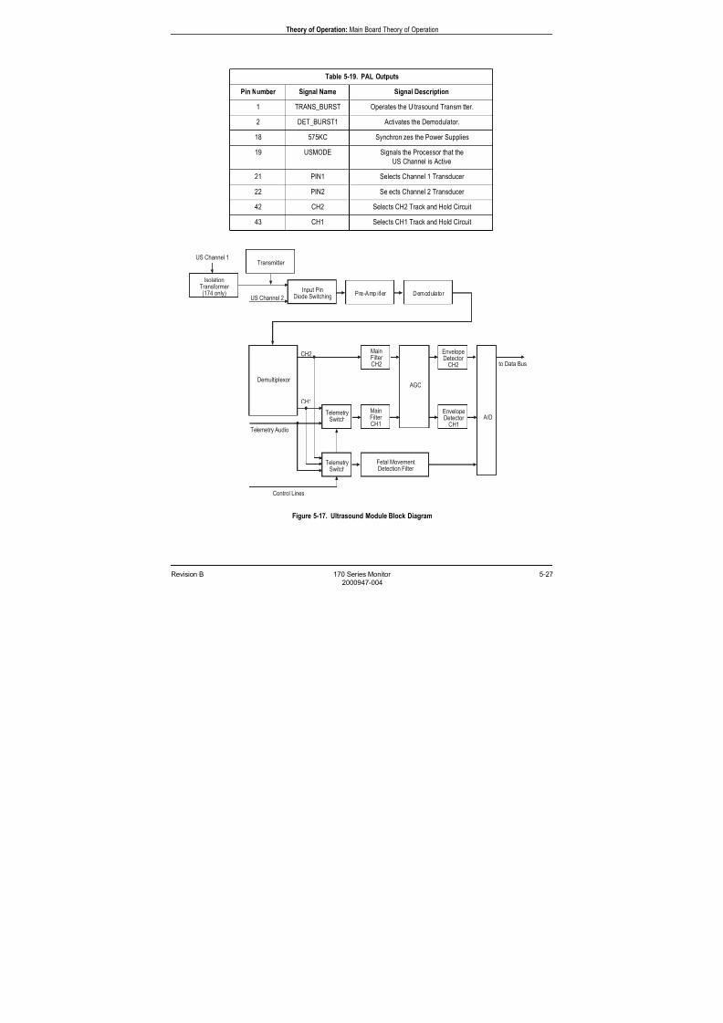
7/25/2019 Serv. Corometrics 170
http://slidepdf.com/reader/full/serv-corometrics-170 85/254
Revision B 170 Series Monitor 5-27
2000947-004
Theory of Operation: Main Board Theory of Operation
Figure 5-17. Ultrasound Module Block Diagram
Table 5-19. PAL Outputs
Pin Number Signal Name Signal Description
1 TRANS_BURST Operates the Ultrasound Transmitter.
2 DET_BURST1 Activates the Demodulator.
18 575KC Synchronizes the Power Supplies
19 USMODE Signals the Processor that the
US Channel is Active
21 PIN1 Selects Channel 1 Transducer
22 PIN2 Selects Channel 2 Transducer
42 CH2 Selects CH2 Track and Hold Circuit
43 CH1 Selects CH1 Track and Hold Circuit
7/25/2019 Serv. Corometrics 170
http://slidepdf.com/reader/full/serv-corometrics-170 86/254
5-28 170 Series Monitor Revision B
2000947-004
Theory of Operation: Main Board Theory of Operation
Ultrasound Oscillator Internal gates located in integrated circuit U50, X4, and associated
components comprise a crystal-controlled oscillator running at 4.604
MHz. The inverted output of this oscillator is the clock that is used to
clock latch U48; therefore changes at the outputs of U50 are not clocked
out of U48 until one-half clock cycle later. The system runs at a
frequency of 2 kHz [(4.604 MHz/1151)/2=2 kHz] and the time for eachtransmission and reception is 250 µs [(1/2000)/2=250 µs]. The signal
TRANS_BURST is a square wave at a frequency of 1.151 MHz. It is
initiated four clock cycles after the internal reset of the binary counter
within U50 used to decode the signals used by the ultrasound system and
continues 428 clock cycles. The signal DET_BURST1 is also a square
waves at a frequency of 1.151 MHz. This signal is output 640 clock cycles
after reset, and continues up to 1020 clock cycles.
Pin Diode CircuitryThe signals PIN1 and PIN2, from PAL U50, turn on the appropriate
switches of U47 so as to bias pin diodes D21 and D22 on; this in turn
provides a low impedance path for the Channel 1 transducer to theultrasound transmitter and preamplifier. Diodes D23 and D24 are
biased off, providing a high impedance path to the ultrasound
transmitter and preamplifier for the Channel 2 transducer. The opposite
of the above is true when the Channel 2 transducer is activated.
Transmission/ReceptionIntegrated circuits U53, U54, and U55 are voltage regulators used to
provide stable, low-noise power supplies for the ultrasound receiver and
transmitter. Transistor Q11, inductor L1, and capacitor C208 form the
ultrasound transmitter. Q11 is driven by the signal TRANS_BURST.
Inductor L2 and capacitors C209, C210, and CV1 provide tuning for the
transmitter output. The transmitter has a nominal output impedance of30 Ω, and can typically drive 4 V peak-to-peak into a 20 Ω load.
Transistors Q12, Q13, and Q14, and associated components, form the
preamplifier. Capacitors C213, C215, C229, and C216 provide power
supply rejection for the preamplifier. Inductor L3, along with capacitors
C211 and C212, form a series resonant tank circuit. This tank circuit
provides a low impedance path for the received signals from the
transducer, and a voltage gain of approximately 28 dB. The typical input
impedance to this tank circuit is 30 Ωs.
Transistors Q12 and Q13 form a cascode amplifier. Transistor Q13 is a
dual n-channel field effect transistor connected in parallel. This parallel
connection provides an improvement of 3 dB in signal-to-noise ratio dueto the gain doubling and the noise adding in quadrature. Inductor L4
and capacitors C214 and CV3 form a parallel resonant tank circuit with
an impedance of approximately 17 kΩs. The shunt impedance of
resistors R388, R389, R390, R391, and R392 effectively lower this
impedance to 3.6 kΩ. The gain of the preamplifier is approximately 19
dB and is defined by:
Rl/((1/(2*gm))+R386)= 3.6k/((1/.002)+200)
7/25/2019 Serv. Corometrics 170
http://slidepdf.com/reader/full/serv-corometrics-170 87/254
Revision B 170 Series Monitor 5-29
2000947-004
Theory of Operation: Main Board Theory of Operation
Transistor Q14 and transformer T1 provide a differential output for the
preamplifier. Diode D19 provides protection for Q13 and removes the
low impedance tank circuit L3 and C211, and C212 during transmission
by shunting L3. Diode D20 provides overload recovery for the
preamplifier and voltage limiting to the demodulator through Q14 and
T1.
U43 is a quad-switched capacitor integrated circuit configured as a
balanced ring demodulator. Its analog inputs are connected to the
differential outputs of the pre-amplifier at the secondary of T1. The
switches within the device are actuated by the signal DET_BURST1.
The two analog outputs of U43 drive the difference amplifier U44 and its
associated components. Integrated circuit U45 switches the output of
the difference amplifier U44 (pin 14) to the track-and-hold circuit of
either Channel 1 or Channel 2.
The track-and-hold circuit for Channel 1 is comprised of components
R408, C225, and buffer amplifier U46 (pin 7). The track-and-hold circuit
for Channel 2 is comprised of components R409, C226 and buffer
amplifier U46 (pin1).
The track-and-hold circuits retain the amplitude of the last value from
the previous demodulator activation. If this method were not employed,
the system gain would have to be twice as high since it is a time sampled
system. The samples must be integrated over time (averaged) to produce
the desired output. In summary, this method improves the signal-to-
noise ratio of the system.
Since the DET signal is driven at the same frequency as the transmitted
signal, any return signal of the same frequency will be averaged and
produce either 0 V or a dc offset at the output of the demodulator; this is
not seen by the main filter driven by the demodulator since it is AC
coupled by capacitors C253 and C262. Therefore, a difference frequency(Doppler shift frequency) must be present to produce an output from the
demodulator. The output of the track-and-hold circuit of Channel 1 at
U46 (pin 7) is switched to the Channel 1 main filter through U39 (pin 11)
to U39 (pins 6 and 10).
Telemetry (if present) is switched to the Channel 1 main filter through
U39 (pin 7) to U39 (pins 6 and 10). Telemetry FECG (if present) is
switched by U39 (pin 3) to U39 (pins 2 and 15) to the analog-to-digital
converter. The main filter is a band-pass amplifier. Its 3 dB points are
120 Hz and 300 Hz, respectively. The bandwidth slopes are greater than
40 dB/octave. The maximum gain of the filter is 46 dB with peaking of
approximately 48 dB at 250 Hz. The nominal gain in the system is
approximately 36 dB and is controlled by R454. The Channel 1 main
filter is comprised of U51 and associated components.
7/25/2019 Serv. Corometrics 170
http://slidepdf.com/reader/full/serv-corometrics-170 88/254
5-30 170 Series Monitor Revision B
2000947-004
Theory of Operation: Main Board Theory of Operation
FilteringThe main filter is a band-pass amplifier with 3 dB points at 120 Hz and
300 Hz, respectively. The band width slopes are greater than 40 dB/
octave. The maximum gain of the filter is 46 dB with peaking of
approximately 48 dB at 250 Hz. The nominal gain in the system is
approximately 36 dB and is controlled by R454. The Channel 1 main
filter is comprised of U51 and associated components.
The output of the track-and-hold circuit of Channel 2 at U46 (pin 1) is
connected directly to the Channel 2 main filter. The main filter is a band-
pass amplifier with 3 dB points are 120 Hz and 300 Hz, respectively. The
band width slopes are greater than 40 dB/octave. The maximum gain of
the filter is 46 dB with peaking of approximately 48 dB at 250 Hz. The
nominal gain in the system is approximately 36 dB and is controlled by
R467. The Channel 2 main filter is comprised of U52 and associated
components. Integrated circuit U40 switches the output of either the
Channel 1 demodulator, the Channel 2 demodulator, or telemetry audio
to the fetal movement band-pass filter. This filter has a gain of 3.5 and
corner frequencies of 15 Hz. and 39 Hz, respectively. It is comprised of
U41 and associated components. The output of the fetal movement filteris input to the analog-to-digital converter.
The output of the main filters are input to U10 through capacitors C44
and C45. The input impedance of these inputs is 10 kΩ, thus producing a
high-pass filter at 72 Hz. A tone is also one of the inputs to U10 through
a high-pass filter at 15 Hz and a gain reduction of –21 dB. The
components comprising the filter are C47 and R223. U10 is a quad
digital potentiometer with 255 step producing a gain range from 0 to
–48 dB. It is controlled by the serial peripheral interface (SPI) system
bus.
Ultrasound Audio Ultrasound audio (Channel 1 and Channel 2) is output on U10 (pin 8)
and U10 (pin 4), respectively. These outputs are buffered by U11 (pin 7)
and U11 (pin 8), respectively. The buffered outputs are high-pass
filtered at 80 Hz by C57/R236 and C58/R237. They are then half-wave
rectified by U13 (pin 8) and its associated components. The output of the
rectifier is band-pass filtered from 43 to 260 Hz at a gain of 7.3 by U13
(pin 1) and its associated components. This effectively doubles the
frequency which is necessary because the transducer operates at a low
RF frequency (1.151 MHz); and the frequencies produced from the fetal
heart would not produce acceptable audio quality.
The output of U13 (pin 1) is input to summing amplifier U11 (pin 14).
The tone output of U10 (pin 18) is also summed by U11 (pin 14) which isa low-pass filter at 2600 Hz with a slope of –12dB/octave. The output of
U11 (pin 14) is high-pass filtered at 72 Hz by C52/R231 to the audio
power amplifier.
The audio power amplifier U12 is a bridge type configuration with a gain
of 2.5 and capable of delivering 1.5 W of power into 8 Ω. Figure 5-18
provides block diagram of the audio module.

7/25/2019 Serv. Corometrics 170
http://slidepdf.com/reader/full/serv-corometrics-170 89/254
Revision B 170 Series Monitor 5-31
2000947-004
Theory of Operation: Main Board Theory of Operation
Figure 5-18. Audio Module Block Diagram
Ultrasound EnvelopesThe outputs of the main filters are also input to U32 and U35. The input
to U35 is through high-pass filters at 63 Hz. The high pass components
for Channel 1 and Channel 2 are C154/R338 and C159/R357,
respectively. The output of the main filters are also input to U32; this
integrated circuit, in conjunction with U35, forms an AGC (automatic
gain control) circuit for both ultrasound channels.
Each of these AGC circuit has a maximum gain of 200 with a dynamic
range of 46 dB. Each of the AGC outputs are high-pass filtered byC169/R343 at 90 Hz with a gain of one, then input to a half-wave detector
U36 (pin 7) with a gain of 1.47. The output of the detector circuits are
low-pass filtered by U36 (pin 1)at 20 Hz at gain of ten.
These envelopes are then input to the analog-to-digital converter U38.
Other inputs to the analog-to-digital converter are the telemetry TOCO
signal. This signal is scaled and offset to provide –100 to +400 relative
UA units.
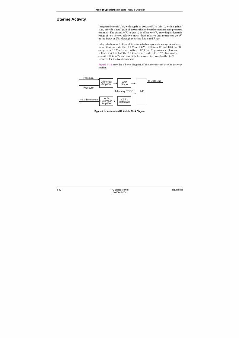
7/25/2019 Serv. Corometrics 170
http://slidepdf.com/reader/full/serv-corometrics-170 90/254
5-32 170 Series Monitor Revision B
2000947-004
Theory of Operation: Main Board Theory of Operation
Uterine Activity
Integrated circuit U33, with a gain of 200, and U34 (pin 7), with a gain of
1.25, provide a total gain of 250 for the on-board tocotransducer pressure
channel. The output of U34 (pin 7) is offset +0.5 V, providing a dynamic
range of –80 to +400 relative units. Each relative unit represents 20 µ V
at the input of U33 through resistors R318 and R320.
Integrated circuit U42, and its associated components, comprise a charge
pump that converts the +3.3 V to –3.3 V. U38 (pin 11) and U34 (pin 1)
comprise a 2.5 V reference voltage. U71 (pin 7) provides a reference
voltage which is half the 2.5 V reference, called VREF/2. Integrated
circuit U56 (pin 7), and associated components, provides the +4 V
required for the tocotransducer.
Figure 5-19 provides a block diagram of the antepartum uterine activity
section.
Figure 5-19. Antepartum UA Module Block Diagram

7/25/2019 Serv. Corometrics 170
http://slidepdf.com/reader/full/serv-corometrics-170 91/254
Revision B 170 Series Monitor 5-33
2000947-004
Theory of Operation: Main Board Theory of Operation
Power Supplies
Integrated circuit U60 is a voltage comparator that senses that the
power has been removed, and inhibits battery RAM access and recorder
printing when the supply drops to approximately 10 V.
Integrated circuit U58 forms an R-S flip-flop. U58 (pin 6) is set highwhen the Power button is pressed. Q19 collector also goes to a logic 1
whenever the Power button is pressed. When U58 (pin 6) is pulled high,
it enables the SYNC signal at U59 (pin 4) which is inverted by U59 (pin
3) to reach all the switching power supplies. The sync frequency is 575
kHz and is derived, and hence synchronized to the ultrasound system.
U62 and its associated components comprise a buck converter with an
output voltage of +5.8 V. This is used as the pre-regulator for linear
regulators U65, U66, U68, and U69. U65 provides the system +5 V. U66
provides the +5 V for the recorder motor. U67 provides the +5 V for the
audio amplifier. U68 provides +3.3 V for the analog circuitry. U69
provides the +3.3 V for the digital circuitry. U61, and its associated
components, comprise a linear regulator with an output voltage of +7.5
V. This is used as the pre-regulator for the linear regulator U55 whichprovides the +6 V for the ultrasound front end; it also powers U53 which
provides the –6 V and powers U56 which is used to generate the +4 V for
the tocotransducer circuitry. U64, and its associated components,
comprise a boost converter with an output voltage of +24 V.
Integrated circuit U70, under microprocessor control, is used to control
the +24 V for the recorder printhead. The +24 V output is current
limited by Q20, Q21, and associated components. The power output is
limited to 17 W.
Figure 5-20 provides a block diagram of the power supply section.
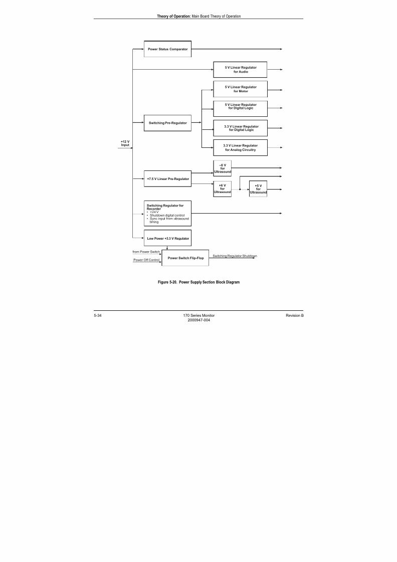
7/25/2019 Serv. Corometrics 170
http://slidepdf.com/reader/full/serv-corometrics-170 92/254
5-34 170 Series Monitor Revision B
2000947-004
Theory of Operation: Main Board Theory of Operation
Figure 5-20. Power Supply Section Block Diagram
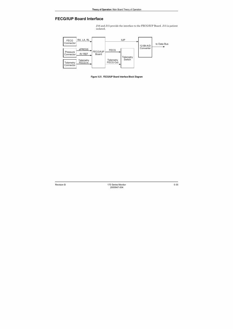
7/25/2019 Serv. Corometrics 170
http://slidepdf.com/reader/full/serv-corometrics-170 93/254
Revision B 170 Series Monitor 5-35
2000947-004
Theory of Operation: Main Board Theory of Operation
FECG/IUP Board Interface
J16 and J15 provide the interface to the FECG/IUP Board. J15 is patient
isolated.
Figure 5-21. FECG/IUP Board Interface Block Diagram

7/25/2019 Serv. Corometrics 170
http://slidepdf.com/reader/full/serv-corometrics-170 94/254
5-36 170 Series Monitor Revision B
2000947-004
Theory of Operation: FECG/IUP Board Theory of Operation
FECG/IUP Board Theory of Operation
Isolated Power Supply
Patient isolation for the FECG and the IUP catheter is accomplished by
providing floating power supplies to power the FECG and IUP front end
electronics. Integrated circuit U12 provides non-overlapping drive
signals to dual FET U9 which in turn drives the primary of transformer
T1. Resistor R94 and capacitor C12 provide dampening for the primary of
T1 so as to limit the voltage at the drains of U9 to a level below their
breakdown voltage. The frequency at which the primary of T1 is switched
is 35968.75 Hz which is derived by dividing the signal 144 kHz by four.
The actual frequency of this signal is 143875 Hz and is derived from the
PAL U50 in the ultrasound circuit. Thus the transformer switching
frequency is synchronized to the ultrasound circuit. The secondary of
transformer T1 drives rectifiers D9 and D10. These rectifiers are filtered
by C8 and C10 for the positive power supply, and by C9 and C11 for the
negative power supply. Integrated circuit U3 and its associatedcomponents provide a regulated positive voltage (+10 V for Model 173;
+9.3 V for Model 174), while integrated circuit U4 provide a regulated
negative voltage (–10 V for Model 173; –9.3 V for Model 174). Integrated
circuit U1 is a positive precision 2.5 volt reference. The output of U1 is
input to the non inverting input of amplifier U2 (pin 3). The output of
this amplifier U2 (pin 1) drives the emitter follower Q1. The gain of the
amplifier-emitter follower is 1.6 and is set by resistors R3 and R4. The
output of Q1 emitter is 4 V (1.6 x 2.5). This voltage is used to power
either an IUP transducer or tocotransducer. Resistor R1 in the collector
of Q1 is used to sense the current drain from other manufacturers of IUP
transducers who don't have an IUP enable associated with them. When
the voltage at the junction of resistors R36 and R37 falls below 1.164 V
(4 mA) the output of the voltage comparator U16 (pin 8) switches from ahigh state to a low state, which in turn causes transistor Q3 to turn on
and transfer the IUP enable across the isolated barrier. This signal is
named IUPEN*. However If a tocotransducer is present, this signal is
ignored. Transistor Q3 can also be turned on by the signal PEN*.
For Model 173 and 174 Monitors, integrated circuit U33 and associated
components provide regulation of the power supplied to the FECG/IUP
Board circuitry (+12 V for Model 173; +11.6 V for Model 174).
For a Model 174 only, the CLEAR signal synchronizes the counter in the
PAL; this in effect stops the power supply during the receive cycle of the
ultrasound process for noise reduction purposes.
7/25/2019 Serv. Corometrics 170
http://slidepdf.com/reader/full/serv-corometrics-170 95/254
Revision B 170 Series Monitor 5-37
2000947-004
Theory of Operation: FECG/IUP Board Theory of Operation
Pressure Channel
The input to the pressure channel is to resistors R9 and R10 with the
signal names of –PRESS and +PRESS respectively. Resistors R9 through
R12 and capacitors C16 through C18 provide RF filtering, and in
conjunction with diode limiters D1 and D2, provide protection from
electro-static discharge.Instrumentation amplifier U5 provides a gain of248 which is given by (49.4E3/R13)+1. The output of U5 which is
inverting with respect to the signal –PRESS, drives the inverting
amplifier U6 (pin 1). This amplifier has a gain of –4.99 and rolls off at
approximately 32 Hz. The output of U6 (pin 1) drives U6 (pin 5) with a
division of two formed by resistors R18 and R19. The operation of this
amplifier is best understood if analyzed from its quiesent condition of no
input signal. Under this condition U6 (pin 5) is at zero volts, therefore U6
(pin 6) must also be at zero volts. This forces a quiesent current of 75 µ A
through R20. This current is produced by U6 (pin 7) driving the LED
that illuminates the photodiode at U10 (pins 3 and 4) which is the
feedback path. The LED also illuminates the photodiode at U10 (pins 5
and 6) which are on the non-isolated side. The current transfer ratio of
this photodiode with respect to the photodiode on U10 (pins 3 and 4) is
0.85 to 1.05. The tocotransducer and the IUP transducer have the
transfer function of 5µ V/UA-Unit/Volt-excitation. Therefore since the
excitation voltage is 4 V, the input voltage is 0.002V/100UA-Units. This
corresponds to 2.475 V at U6 (pin 1) and 1.2375 Vat U6 (pin 5). This
causes a delta current of 9.3 µ A through R20, which is also transferred
across the barrier with the same transfer ratio of 0.85 to 1.05. This
current is input to U13 (pin 6) through R32. Potentiometer R25 sets the
gain at U13 (pin 8) to 0.5 V/100UA-Units. Potentiometer R30 sets the
initial offset voltage to +0.5 V. The output amplifier U13 (pin 8) is a unity
gain amplifier with 3 poles of filtering with its 3 dB frequency of 3 Hz.
Since the system analog-to-digital converter has an input range of 0 to
2.5 V, the dynamic range is from –100 to +400UA-Units.
7/25/2019 Serv. Corometrics 170
http://slidepdf.com/reader/full/serv-corometrics-170 96/254
5-38 170 Series Monitor Revision B
2000947-004
Theory of Operation: FECG/IUP Board Theory of Operation
FECG Channel
The input to the FECG channel is two resistors R42 and R43 with the
signal names of RA and LA respectively. Resistors R42, R43, R45, and
R462 and capacitors C38 through C40 provide RF filtering, and in
conjunction with diode limiters D3 through D6 provide protection from
electro-static discharge. Resistors R40, R41, and R44 cause amplifier U7to saturate when the FECG cable is not connected to a fetus. This
disables the FECG channel from counting noise and flashing LEDs and
causing tones to be generated by the speaker. Instrumentation amplifier
U7 provides a gain of 13.7 which is given by (49.4E3/R54)+1. Amplifier
U2 (pins 5, 6, and 7) is an integrator which has high gain at DC with
reducing gain as frequency increases.
Amplifier U2 (pin 7) drives amplifier U2 (pin8). Amplifier U2 (pin 8) is
non-inverting and is patient protected in the event of a failure of this
device. The two sections of U2 provide the right leg drive circuit. The
right leg drive is a feedback circuit that provides drive in the opposite
polarity to a common mode voltage. Its purpose is to cancel DC offset
from the electrode, and to help reject 50 and 60 Hz components. Theoutput of U7, which is inverting with respect to the signal RA, drives the
non-inverting amplifier U2 (pin 12) through a high-pass filter of 10 Hz.
Resistor R58 and diode D7 provide voltage limiting at U2 (pin 12). This
amplifier has a gain of 22.5 and rolls off at approximately 224 Hz. The
output of U2 (pin 14) drives U8 (pin 3) through R64. Resistor R64 and
diode D8 provide voltage limiting at U8 (pin 3). This amplifier has a gain
of 22.5 and rolls off at approximately 224 Hz. The composite bandwidth
and gain at this point is from 10 Hz to 320 Hz with a gain of 6936. The
output of U8 (pin 1) drives amplifier U8 (pin 5) with a division of 10/11
formed by resistors R67 and R68. The operation of this amplifier is best
understood if analyzed from its quiesent condition of no input signal.
Under this condition U8 (pin 5) is at zero volts, therefore U8 (pin 6) must
also be at zero volts. This forces a quiesent current of 75 µ A through R69.
This current is produced by U8 (pin 7) driving the LED that illuminates
the photodiode at U11 (pins 3 and 4) which is the feedback path. The
LED also illuminates the photodiode at U11 (pins 5 and 6) which are on
the un-isolated side. The current transfer ratio of this photodiode, with
respect to the photodiode, on U11 (pins 3 and 4) is 0.85 to 1.05. The input
voltage required to drive U8 (pin 1) to either of its power supply limits is
approximately ±1.44 mV peak. This corresponds to approximately ±5 V
at U8 (pin 1) for ±0.72 mV input, and ±4.55 V at U8 (pin 5). This causes a
delta current of 34.2 µ A through R69, which is also transferred across the
barrier with the same transfer ratio of 0.85 to 1.05. This current is input
to U15 (pin 3) with resistor R75 being the load resistor that produces a
voltage proportional to the current transferred to it. Amplifier U15 (pin7) produces an offset voltage of –1.97 V. The quiesent current of 75 µ A
flowing through R75 will produce a voltage of approximately +1.25 V at
U15 (pin 3). A 0.72 mV signal peak-to-peak at the input will produce
approximately 1.26 V at U15 (pin 1). Thus ±1.44 mV at the input will
produce ±2.52 V at U15 (pin 8). Amplifier U15 (pin 14) is a non-inverting
amplifier with a gain of one. It also provides 3 sections of high-pass
filtering at 25 Hz. Amplifier U15 (pin 8) is a non-inverting amplifier with
a gain of one. It also provides 3 sections of low-pass filtering at 90 Hz.
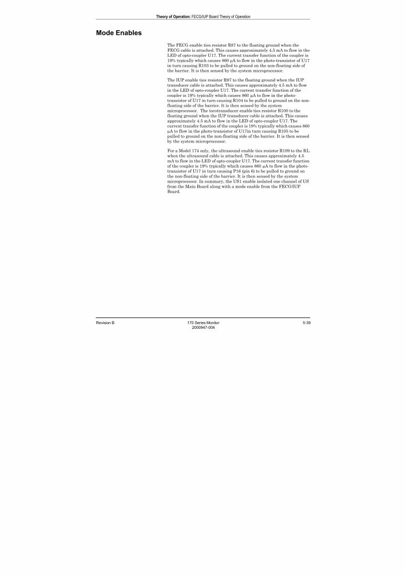
7/25/2019 Serv. Corometrics 170
http://slidepdf.com/reader/full/serv-corometrics-170 97/254
Revision B 170 Series Monitor 5-39
2000947-004
Theory of Operation: FECG/IUP Board Theory of Operation
Mode Enables
The FECG enable ties resistor R87 to the floating ground when the
FECG cable is attached. This causes approximately 4.5 mA to flow in the
LED of opto-coupler U17. The current transfer function of the coupler is
19% typically which causes 860 µ A to flow in the photo-transistor of U17
in turn causing R103 to be pulled to ground on the non-floating side ofthe barrier. It is then sensed by the system microprocessor.
The IUP enable ties resistor R97 to the floating ground when the IUP
transducer cable is attached. This causes approximately 4.5 mA to flow
in the LED of opto-coupler U17. The current transfer function of the
coupler is 19% typically which causes 860 µ A to flow in the photo-
transistor of U17 in turn causing R104 to be pulled to ground on the non-
floating side of the barrier. It is then sensed by the system
microprocessor. The tocotransducer enable ties resistor R100 to the
floating ground when the IUP transducer cable is attached. This causes
approximately 4.5 mA to flow in the LED of opto-coupler U17. The
current transfer function of the coupler is 19% typically which causes 860
µ A to flow in the photo-transistor of U17in turn causing R105 to bepulled to ground on the non-floating side of the barrier. It is then sensed
by the system microprocessor.
For a Model 174 only, the ultrasound enable ties resistor R109 to the RL
when the ultrasound cable is attached. This causes approximately 4.5
mA to flow in the LED of opto-coupler U17. The current transfer function
of the coupler is 19% typically which causes 860 µ A to flow in the photo-
transistor of U17 in turn causing P16 (pin 6) to be pulled to ground on
the non-floating side of the barrier. It is then sensed by the system
microprocessor. In summary, the US1 enable isolated one channel of US
from the Main Board along with a mode enable from the FECG/IUP
Board.
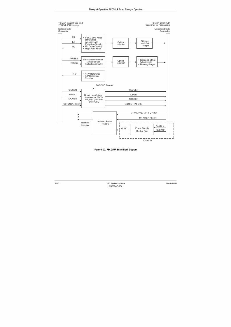
7/25/2019 Serv. Corometrics 170
http://slidepdf.com/reader/full/serv-corometrics-170 98/254
5-40 170 Series Monitor Revision B
2000947-004
Theory of Operation: FECG/IUP Board Theory of Operation
Figure 5-22. FECG/IUP Board Block Diagram
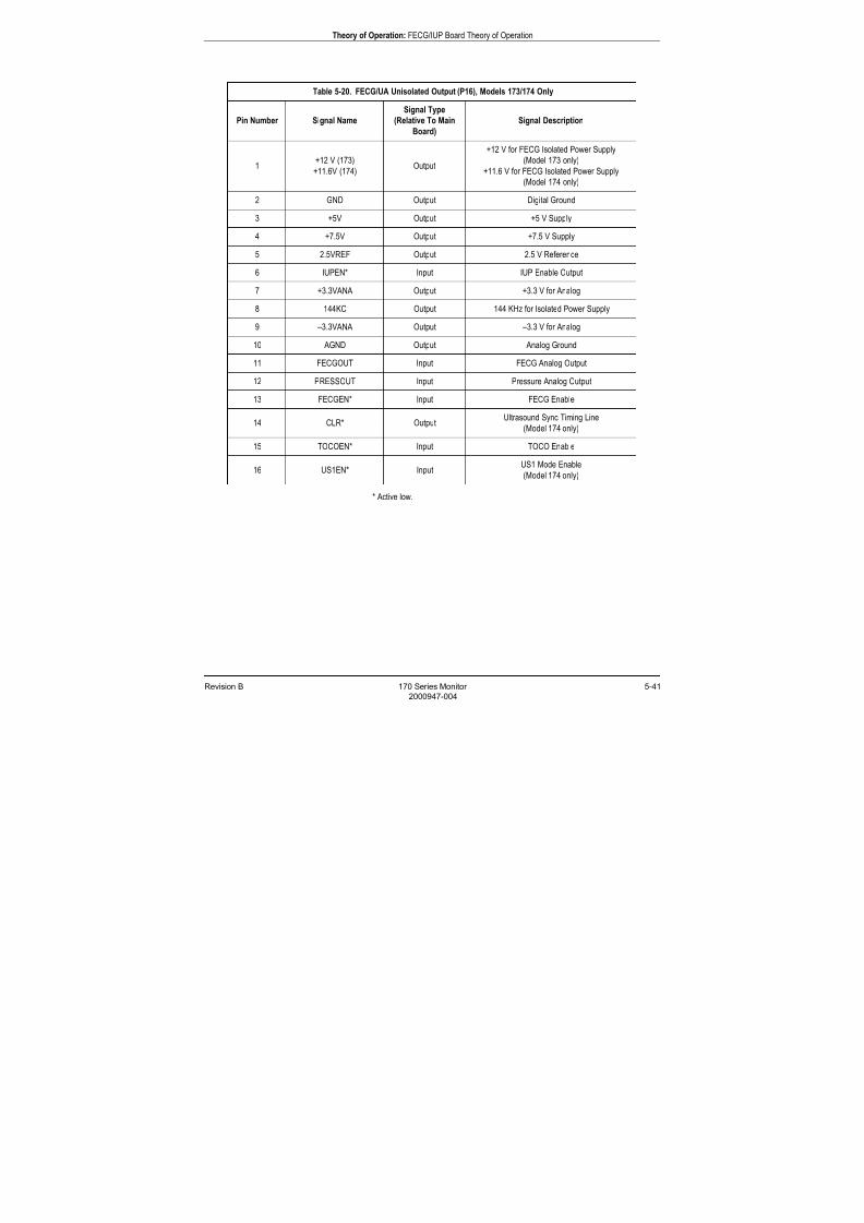
7/25/2019 Serv. Corometrics 170
http://slidepdf.com/reader/full/serv-corometrics-170 99/254
Revision B 170 Series Monitor 5-41
2000947-004
Theory of Operation: FECG/IUP Board Theory of Operation
* Active low.
Table 5-20. FECG/UA Unisolated Output (P16), Models 173/174 Only
Pin Number Signal Name
Signal Type
(Relative To Main
Board)
Signal Description
1+12 V (173)
+11.6V (174)Output
+12 V for FECG Isolated Power Supply
(Model 173 only)
+11.6 V for FECG Isolated Power Supply
(Model 174 only)
2 GND Output Digital Ground
3 +5V Output +5 V Supply
4 +7.5V Output +7.5 V Supply
5 2.5VREF Output 2.5 V Reference
6 IUPEN* Input IUP Enable Output
7 +3.3VANA Output +3.3 V for Analog
8 144KC Output 144 KHz for Isolated Power Supply
9 –3.3VANA Output –3.3 V for Analog
10 AGND Output Analog Ground
11 FECGOUT Input FECG Analog Output
12 PRESSOUT Input Pressure Analog Output
13 FECGEN* Input FECG Enable
14 CLR* OutputUltrasound Sync Timing Line
(Model 174 only)
15 TOCOEN* Input TOCO Enable
16 US1EN* InputUS1 Mode Enable
(Model 174 only)

7/25/2019 Serv. Corometrics 170
http://slidepdf.com/reader/full/serv-corometrics-170 100/254
5-42 170 Series Monitor Revision B
2000947-004
Theory of Operation: FECG/IUP Board Theory of Operation
* Active low.
Table 5-21. FECG/UA Isolated Output (P15), Models 173/174 Only
Pin Number Signal Name
Signal Type
(Relative To Main
Board)
Signal Description
1 RA Output Right Arm Input from Patient Connector
2 LA Output Left Arm Input from Patient Connector
3 RL Input Right Leg Drive Signal from FECG Board
4 SHIELDF Output Isolated Shield
5 –PRESS Output UA Channel Negative Input
6 +PRESS Output UA Channel Positive Input
7 ISO4V Input Isolated 4 V Reference
8 ECGEN* Output Enable for FECG Cable
9 4VISOGND Input Isolated 4 V Reference Ground
10 PEN* Output Isolated IUP Enable
11 USEN* (174 only) OutputUS1 Mode Enable
(Model 174 only)
12 ENTOCO* Output Isolated TOCO Enable
7/25/2019 Serv. Corometrics 170
http://slidepdf.com/reader/full/serv-corometrics-170 101/254
Revision B 170 Series Monitor 6-1
2000947-004
Chapter 6
Functional Checkout
Procedure 6Like all electronic monitoring devices, internal and external components
are subject to fatigue, wear, and the potential for failure over time and
under varying conditions of use. Additionally, events such as dropping
the monitor, spilling liquids on the monitor, or crimping the lead wires orpatient cables can cause damage which may affect the overall system
performance.
This chapter contains the following:
Equipment Required . . . . . . . . . . . . . . . . . . . . . . . . . . . . . . . 6-2
General . . . . . . . . . . . . . . . . . . . . . . . . . . . . . . . . . . . . . . . . . . 6-3
Monitor Self-Test . . . . . . . . . . . . . . . . . . . . . . . . . . . . . . . . . . 6-4
Front Panel Pushbutton Test . . . . . . . . . . . . . . . . . . . . . . . . 6-5
Connecting the Simulator . . . . . . . . . . . . . . . . . . . . . . . . . . . 6-6
FECG Test . . . . . . . . . . . . . . . . . . . . . . . . . . . . . . . . . . . . . . . 6-7
Legplate Inspection . . . . . . . . . . . . . . . . . . . . . . . . . . . . . . . 6-12Ultrasound Test . . . . . . . . . . . . . . . . . . . . . . . . . . . . . . . . . . 6-13
Fetal Movement Detection Test . . . . . . . . . . . . . . . . . . . . . 6-16
Ultrasound Transducer Test . . . . . . . . . . . . . . . . . . . . . . . . 6-18
Uterine Activity Test . . . . . . . . . . . . . . . . . . . . . . . . . . . . . . 6-19
Tocotransducer Test. . . . . . . . . . . . . . . . . . . . . . . . . . . . . . . 6-21
Strain Gauge Transducer Test . . . . . . . . . . . . . . . . . . . . . . 6-22
Pattern Memory Test . . . . . . . . . . . . . . . . . . . . . . . . . . . . . . 6-23
Dual Heart Rate Test (Non-Pattern). . . . . . . . . . . . . . . . . . 6-24
Alarm Test . . . . . . . . . . . . . . . . . . . . . . . . . . . . . . . . . . . . . . 6-28

7/25/2019 Serv. Corometrics 170
http://slidepdf.com/reader/full/serv-corometrics-170 102/254
6-2 170 Series Monitor Revision B
2000947-004
Functional Checkout Procedure: Equipment Required
Equipment Required
Table 6-1 provides a complete listing of equipment required for a
functional checkout procedure.
Table 6-1. Equipment Required
Test Equipment
FECG Model 325 Simulator (14203A/B)
Monitor Interconnect Cable (14212A/B)
Legplate Legplate for Qwik Connect Plus with round connector
(1590AAO)
US/FMD Model 325 Simulator (14203A/B)
Monitor Interconnect Cable (14212A/B)
US Transducer Nautilus Ultrasound Transducer
(5700GAX–5700MAX Series)
TOCO/IUP Model 325 Simulator (14203A/B)
Monitor Interconnect Cable (14212A/B)
Tocotransducer Nautilus Tocotransducer
(2264GAX–2264MAX Series)
Strain Gauge Transducer
Reusable Strain Gauge with holder (4007BAX); or
Reusable Strain Gauge without holder (4007LAX); or
Disposable Strain Gauge (4009AAX)
NOTE: These items are no longer sold by GE. However,
transducers in the field are compatible with the 170
Series Monitor.
Pattern Memory Model 325 Simulator (14203A/B)
Monitor Interconnect Cable (14212A/B)
Dual Heart Rate (FECG/US) Model 325 Simulator (14203A/B)
Monitor Interconnect Cable (14212A/B)
Dual Heart Rate (US/US2)
Two Model 325 Simulators (14203A/B) with two sets
of Monitor Interconnect Cables (14212A/B); or
Two Nautilus Ultrasound Transducers
5700GAX–5700MAX Series)
Alarms Model 325 Simulator (14203A/B)
Monitor Interconnect Cable (14212A/B)

7/25/2019 Serv. Corometrics 170
http://slidepdf.com/reader/full/serv-corometrics-170 103/254
Revision B 170 Series Monitor 6-3
2000947-004
Functional Checkout Procedure: General
General
Between Factory Service visits it is necessary that the proper operation
of each monitor be verified by performing the functional checkout
procedure described in this section. This procedure should be completed
prior to initially placing the monitor on a patient, when monitorperformance needs to be verified, on a semi-annual basis, or more
frequently as dictated by your equipment maintenance and management
policies.
NOTE Read each step of this procedure thoroughly before actually
performing the test.
Visually inspect the monitor, patient cables, and other accessories for
cracks, fissures, or other signs of wear or damage. Do not use any
monitor or accessory which appears to be worn or damaged. If unsure,
contact your GE Service Representative to arrange for evaluation,
replacement, or repair of the suspect item(s).
7/25/2019 Serv. Corometrics 170
http://slidepdf.com/reader/full/serv-corometrics-170 104/254
6-4 170 Series Monitor Revision B
2000947-004
Functional Checkout Procedure: Monitor Self-Test
Monitor Self-Test
The 170 Series Monitor contains test routines which verify the unit’s
calibration and internal circuitry. These routines are initiated by each
time the monitor is turned on. The test results are printed on the strip
chart recorder paper, verifying the integrity of the unit.
This information is covered in detail in “Monitor Self-Test Routines” on
page 4-8.
7/25/2019 Serv. Corometrics 170
http://slidepdf.com/reader/full/serv-corometrics-170 105/254
Revision B 170 Series Monitor 6-5
2000947-004
Functional Checkout Procedure: Front Panel Pushbutton Test
Front Panel Pushbutton Test
This procedure ensures the functionality of the front panel pushbuttons.
1. Disconnect all transducers from the front panel.
2. Enter the service setup mode (see page 4-10) and set the recorderspeed to 1 cm/min.
3. Press the Setup button to exit the setup mode.
4. Press the monitor’s Power button to turn on the monitor.
5. Press the monitor’s Record button and verify the following:
The yellow indicator next to the button illuminates continuously.
The recorder paper advances at a rate of 1 cm/min.
The recorder prints the correct time and date information on the
strip chart paper. (If an incorrect time or date is listed, refer to
“Chapter 4, Setup Procedures” in this manual.) The recorder prints the messages CARDIO INOP and UA INOP,
indicating that no ultrasound or uterine activity transducers are
plugged into the front panel US, US2, or UA connectors.
The recorder prints the message 1 CM/MIN, indicating the selected
chart speed.
6. Press the monitor’s front panel Paper Advance pushbutton and verify
that the recorder paper advances at a rate of 36 cm/min.
7. Press the Paper Advance pushbutton again and verify that the
recorder prints the message 1 CM/MIN.
8. Access the service setup mode and set the recorder speed to3 cm/min.
9. Press the Setup button to exit the service setup mode.
10. Press the monitor’s Power button to turn the monitor back on.
11. Verify that the recorder paper advances at a rate of 3 cm/min and
that after approximately 40 seconds, the message 3 CM/MIN prints on
the recorder paper. (The time, date and monitoring modes also print
again.)
12. Press the Mark button and verify that an event mark ( ) prints on the
bottom two lines of the recorder paper.
7/25/2019 Serv. Corometrics 170
http://slidepdf.com/reader/full/serv-corometrics-170 106/254
6-6 170 Series Monitor Revision B
2000947-004
Functional Checkout Procedure: Connecting the Simulator
Connecting the Simulator
This part of the procedure prepares the simulator for use.
NOTE You must use a Model 325 Simulator for the functional checkout
procedure. (Monitors in the 170 Series do not work with Model305 Simulators.)
1. Ensure the Model 325 Power switch is in the off position.
2. Connect the Model 325 Simulator’s power cord to the power
receptacle on the rear panel of the simulator; plug the other end of
the power cord into a properly grounded wall outlet of appropriate
voltage.
3. Ensure the 170 Series Monitor is turned off.
4. Connect the simulator interconnect cable’s 50-pin end to the
simulator’s Fetal Monitor connector.
5. Connect the sub-cables of the other end of the simulator interconnectcable into the color-coded connectors on the monitor/adapter: US and
UA (as required by the procedure).
6. Turn on the Model 325 Simulator. Verify that the green Power
indicator illuminates.
7. Turn on the 170 Series Monitor.
7/25/2019 Serv. Corometrics 170
http://slidepdf.com/reader/full/serv-corometrics-170 107/254
Revision B 170 Series Monitor 6-7
2000947-004
Functional Checkout Procedure: FECG Test
FECG Test
This portion of the functional checkout procedure ensures the integrity of
the FECG circuitry and the heart rate channel of the recorder.
1. Connect the Model 325 Simulator’s ECG sub-cable to the FECG receptacle on the monitor
2. Set the switches on the Model 325 Input Simulator according to
Table 6-2.
3. If not already on, press the monitor’s Record button.
4. Turn the simulator’s Manual Adjustment knob fully counterclockwise and
verify the following on the monitor:
The FHR1 value is 30 BPM.
The FHR1 heartbeat indicator ( ) flashes at a rate of 30 times per
minute.
The ECG “beep” volume of the rear panel speaker can be increased ordecreased using the Volume buttons. (Set the volume to the desired
level.)
The recorder prints a continuous line at 30 BPM on the top grid of
the strip chart paper.
The recorder prints the message FECG on the center margin of
the strip chart paper after approximately 20 seconds.
5. Turn the simulator’s Manual Adjustment knob to input an FECG signal of
approximately 120 BPM. Verify the following on the monitor:
The FHR1 value is 120 BPM.
FHR1 heartbeat indicator ( ) flashes at a rate of 120 times perminute.
The ECG “beep” volume of the rear panel speaker can be
increased or decreased using the Volume buttons. (Set the volume
to the desired level.)
The recorder prints a continuous line at 120 BPM on the strip
chart paper.

7/25/2019 Serv. Corometrics 170
http://slidepdf.com/reader/full/serv-corometrics-170 108/254
6-8 170 Series Monitor Revision B
2000947-004
Functional Checkout Procedure: FECG Test
6. Repeat step 5 for each of the following rates: 60, 210, and 240 BPM.
7. Change the simulator’s QRS Polarity switch from + to –. Verify that the
monitor does not skip any beats.
8. Set the simulator’s ECG Rate switch to the RAMP setting. Verify that
the monitor’s FHR1 value counts between approximately 30 and 240
BPM and that the FHR1 trend is a ramp between the same values on
the strip chart paper. (See Figure 6-1.)
9. Access the Service Setup Mode and disable ECG Artifact
Elimination.
10. Set the simulator’s ECG Rate switch to the ∆15 position. Verify thefollowing on the monitor:
The FHR1 value oscillates by 15 BPM.
The FHR1 heartbeat indicator ( ) flashes for each input signal.
The ECG “beep” is heard from the rear panel speaker.
The FHR trend oscillates 15 BPM between 115 and 130 BPM on
the top grid of the strip chart paper. (See Figure 6-2.)
11. Repeat step 10 for rate values of ∆22 and ∆27. The results should be
the same except that the FHR1 value oscillates by either 22 or 27
BPM and the FHR trend is an oscillation of 22 or 27 BPM. The top
value is always at approximately 130 BPM. (Refer to Figure 6-2.)
12. Access the Service Setup Mode and enable ECG Artifact Elimination.
Table 6-2. Model 325 Simulator Settings for FECG Test
Section Switch Setting
FECG/MECG
Main RATE
Rate MANUAL
Mode FECG
QRS Amplitude 15 µV
QRS Polarity +
GENERAL Pattern Memory OFF
UAMain CMR
Mode TOCO

7/25/2019 Serv. Corometrics 170
http://slidepdf.com/reader/full/serv-corometrics-170 109/254
Revision B 170 Series Monitor 6-9
2000947-004
Functional Checkout Procedure: FECG Test
13. Set the simulator’s ECG Rate switch to the ∆15 position. Verify the
following on the monitor:
The FHR1 value oscillates by 15 BPM.
The FHR1 heartbeat indicator ( ) flashes for each input signal.
The ECG “beep” is heard from the rear panel speaker.
The recorder prints an oscillation of 15 BPM between 115 and130 BPM on the top grid of the strip chart paper. (Figure 6-2.
shows the strip chart paper results.)
14. Repeat step 13 for the rate value of ∆22. The result should be the
same as step 13 except that the FHR1 value oscillates by 22 BPM
and the trend is an oscillation of 22 BPM between the 108 and 130
BPM on the strip chart paper.
15. Set the simulator’s ECG Rate switch to the ∆27 position. Verify the
following on the monitor:
The FHR1 value oscillates by 27 BPM.
The FHR1 heartbeat indicator ( ) flashes for each input signal.
The ECG “beep” is heard from the rear panel speaker.
The trend does not indicate any oscillation.
16. Access the Service Setup Mode and disable ECG Artifact
Elimination.
17. Set the simulator’s ECG Rate switch to the MANUAL position and the
Manual Adjustment knob to the fully counterclockwise position.
Disconnect the ECG simulator sub-cable from the monitor’s FECG
receptacle. Verify the following on the monitor:
The FHR1 value is blank. The FHR1 trend stops plotting on the strip chart paper.
After approximately 30 seconds, the message CARDIO INOP prints
on the center margin of the strip chart paper.
18. Set the simulator’s ECG Mode switch to the OFF position.
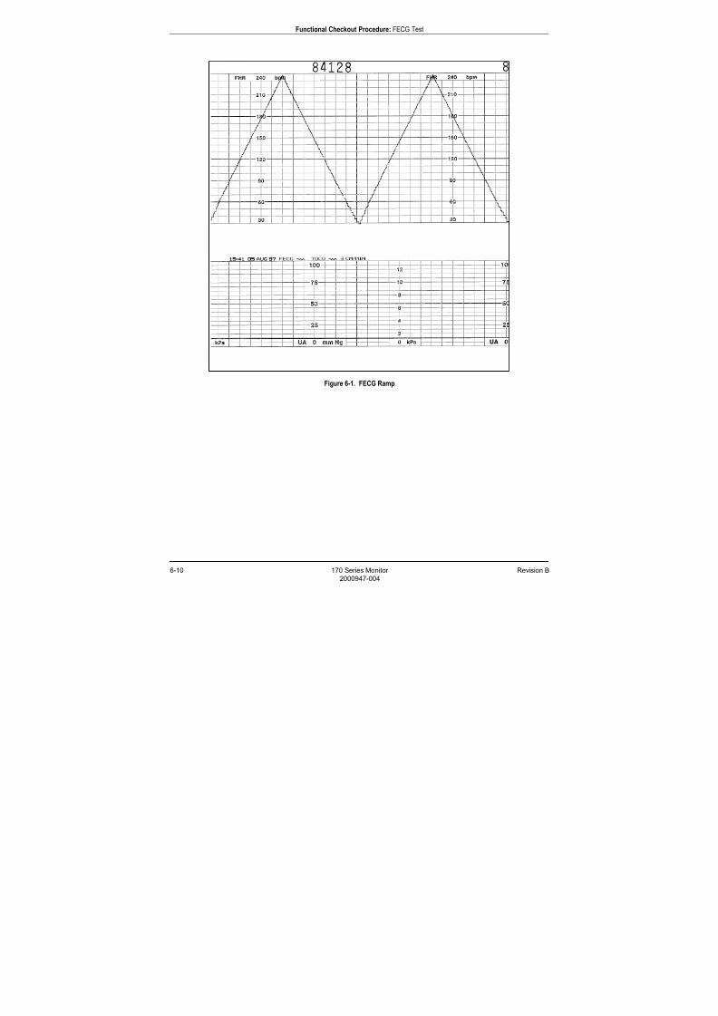
7/25/2019 Serv. Corometrics 170
http://slidepdf.com/reader/full/serv-corometrics-170 110/254
6-10 170 Series Monitor Revision B
2000947-004
Functional Checkout Procedure: FECG Test
Figure 6-1. FECG Ramp
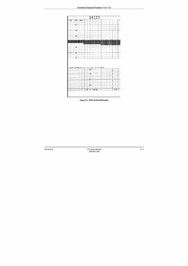
7/25/2019 Serv. Corometrics 170
http://slidepdf.com/reader/full/serv-corometrics-170 111/254
Revision B 170 Series Monitor 6-11
2000947-004
Functional Checkout Procedure: FECG Test
Figure 6-2. FECG Artifact Elimination
7/25/2019 Serv. Corometrics 170
http://slidepdf.com/reader/full/serv-corometrics-170 112/254
6-12 170 Series Monitor Revision B
2000947-004
Functional Checkout Procedure: Legplate Inspection
Legplate Inspection
Inspect the legplate as follows:
1. Check for a proper seal around the ground plate.
2. Ensure that no contaminants are present on either the groundplate or the push posts.
3. Visibly assess the condition of the cable, strain relief, and
connector pins.
7/25/2019 Serv. Corometrics 170
http://slidepdf.com/reader/full/serv-corometrics-170 113/254
Revision B 170 Series Monitor 6-13
2000947-004
Functional Checkout Procedure: Ultrasound Test
Ultrasound Test
This portion of the functional checkout procedure ensures the integrity of
the ultrasound circuitry and the heart rate channel of the recorder.
1. Connect the simulator’s US sub-cable to the US receptacle on themonitor.
2. Set the switches on the Model 325 Input Simulator according to
Table 6-3.
3. If not already on, press the monitor’s Record pushbutton.
4. Turn the simulator’s Manual Adjustment knob to input an ultrasound
signal of approximately 120 BPM. Verify the following on the
monitor:
The FHR1 value is 120 BPM.
The FHR1 heartbeat indicator ( ) flashes at a rate of 120 times
per minute. Ultrasound audio volume from the rear panel speaker can be
increased or decreased using the left pair of Volume pushbuttons.
(Set the volume to the desired level.)
The recorder prints a continuous line at 120 BPM on the top grid
of the strip chart paper.
The recorder prints the message US on the center margin of the
strip chart paper after approximately 20 seconds.
5. Use the simulator’s Manual Adjustment knob to increase the heart rate
value by less than 13 BPM from the 120 BPM baseline. Verify the
following on the monitor:
The FHR1 value immediately reflects this new input rate.
The strip chart recorder immediately reflects this new input rate.
Use the simulator’s Manual Adjustment knob to decrease the heart
rate value by more than 13 BPM from the 120 BPM baseline.
Verify the following on the monitor:
The FHR1 value immediately reflects this new input rate.
The strip chart recorder prints at the last input rate for an
additional 3 seconds before blanking the heart rate data and
printing a continuous line at the new input rate.
6. Set the simulator’s US Rate switch to the RAMP position. Verify that
the FHR1 value counts between approximately 50 and 210 BPM andthat the recorder prints a ramp between the same values. (Refer to
Figure 6-3.)
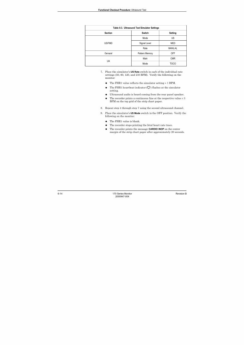
7/25/2019 Serv. Corometrics 170
http://slidepdf.com/reader/full/serv-corometrics-170 114/254
6-14 170 Series Monitor Revision B
2000947-004
Functional Checkout Procedure: Ultrasound Test
7. Place the simulator’s US Rate switch in each of the individual rate
settings (50, 60, 120, and 210 BPM). Verify the following on the
monitor:
The FHR1 value reflects the simulator setting ± 1 BPM.
The FHR1 heartbeat indicator ( ) flashes at the simulator
setting.
Ultrasound audio is heard coming from the rear panel speaker.
The recorder prints a continuous line at the respective value ± 3
BPM on the top grid of the strip chart paper.
8. Repeat step 4 through step 7 using the second ultrasound channel.
9. Place the simulator’s US Mode switch in the OFF position. Verify the
following on the monitor:
The FHR1 value is blank.
The recorder stops printing the fetal heart rate trace.
The recorder prints the message CARDIO INOP on the center
margin of the strip chart paper after approximately 20 seconds.
Table 6-3. Ultrasound Test Simulator Settings
Section Switch Setting
US/FMD
Mode US
Signal Level MED
Rate MANUAL
General Pattern Memory OFF
UAMain CMR
Mode TOCO
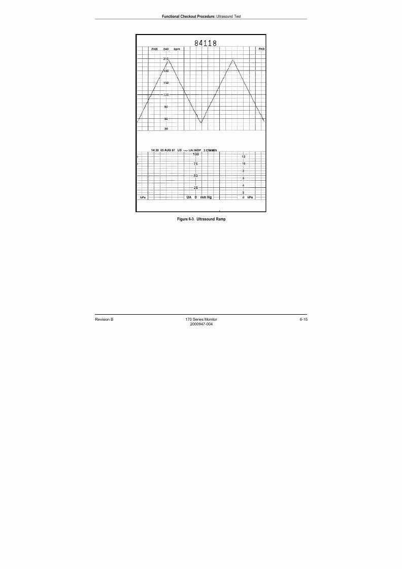
7/25/2019 Serv. Corometrics 170
http://slidepdf.com/reader/full/serv-corometrics-170 115/254
Revision B 170 Series Monitor 6-15
2000947-004
Functional Checkout Procedure: Ultrasound Test
Figure 6-3. Ultrasound Ramp
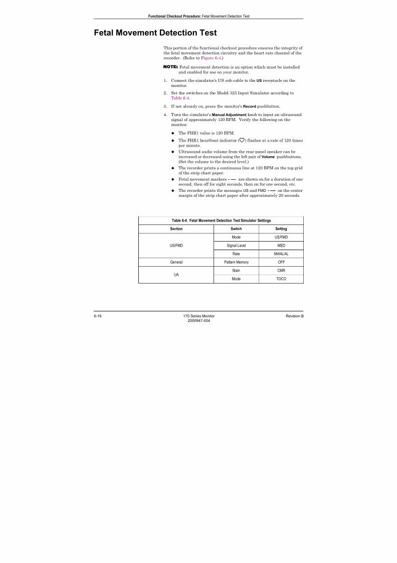
7/25/2019 Serv. Corometrics 170
http://slidepdf.com/reader/full/serv-corometrics-170 116/254
6-16 170 Series Monitor Revision B
2000947-004
Functional Checkout Procedure: Fetal Movement Detection Test
Fetal Movement Detection Test
This portion of the functional checkout procedure ensures the integrity of
the fetal movement detection circuitry and the heart rate channel of the
recorder. (Refer to Figure 6-4.)
NOTE Fetal movement detection is an option which must be installed
and enabled for use on your monitor.
1. Connect the simulator’s US sub-cable to the US receptacle on the
monitor.
2. Set the switches on the Model 325 Input Simulator according to
Table 6-4.
3. If not already on, press the monitor’s Record pushbutton.
4. Turn the simulator’s Manual Adjustment knob to input an ultrasound
signal of approximately 120 BPM. Verify the following on the
monitor:
The FHR1 value is 120 BPM.
The FHR1 heartbeat indicator ( ) flashes at a rate of 120 times
per minute.
Ultrasound audio volume from the rear panel speaker can be
increased or decreased using the left pair of Volume pushbuttons.
(Set the volume to the desired level.)
The recorder prints a continuous line at 120 BPM on the top grid
of the strip chart paper.
Fetal movement markers are shown on for a duration of one
second, then off for eight seconds, then on for one second, etc.
The recorder prints the messages US and FMD on the centermargin of the strip chart paper after approximately 20 seconds.
Table 6-4. Fetal Movement Detection Test Simulator Settings
Section Switch Setting
US/FMD
Mode US/FMD
Signal Level MED
Rate MANUAL
General Pattern Memory OFF
UAMain CMR
Mode TOCO
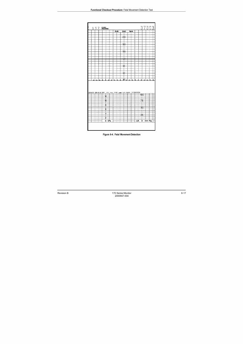
7/25/2019 Serv. Corometrics 170
http://slidepdf.com/reader/full/serv-corometrics-170 117/254
Revision B 170 Series Monitor 6-17
2000947-004
Functional Checkout Procedure: Fetal Movement Detection Test
Figure 6-4. Fetal Movement Detection
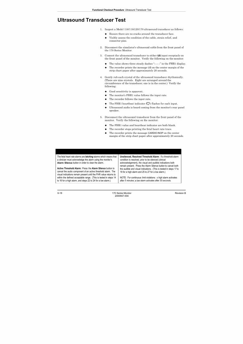
7/25/2019 Serv. Corometrics 170
http://slidepdf.com/reader/full/serv-corometrics-170 118/254
6-18 170 Series Monitor Revision B
2000947-004
Functional Checkout Procedure: Ultrasound Transducer Test
Ultrasound Transducer Test
1. Inspect a Model 116/118/120/170 ultrasound transducer as follows:
Ensure there are no cracks around the transducer face.
Visibly assess the condition of the cable, strain relief, andconnector pins.
2. Disconnect the simulator’s ultrasound cable from the front panel of
the 170 Series Monitor.
3. Connect the ultrasound transducer to either US input receptacle on
the front panel of the monitor. Verify the following on the monitor:
The value shows three steady dashes “– – –” in the FHR1 display.
The recorder prints the message US on the center margin of the
strip chart paper after approximately 20 seconds.
4. Gently rub each crystal of the ultrasound transducer rhythmically.(There are nine crystals. Eight are arranged around the
circumference of the transducer; one is in the center.) Verify the
following:
Good sensitivity is apparent.
The monitor’s FHR1 value follows the input rate.
The recorder follows the input rate.
The FHR1 heartbeat indicator ( ) flashes for each input.
Ultrasound audio is heard coming from the monitor’s rear panel
speaker.
5. Disconnect the ultrasound transducer from the front panel of themonitor. Verify the following on the monitor:
The FHR1 value and heartbeat indicator are both blank.
The recorder stops printing the fetal heart rate trace.
The recorder prints the message CARDIO INOP on the center
margin of the strip chart paper after approximately 20 seconds.
ABOUT LATCHING ALARMS
The fetal heart rate alarms are latching alarms which means that
a clinician must acknowledge the alarm using the monitor’s
Alarm Silence button in order to clear the alarm.
Active Threshold Alarm: Press the Alarm Silence button to
cancel the audio component of an active threshold alarm. The
visual indications remain present until the FHR value returns to
within the defined acceptable range. (This is tested in steps 14
to 16 for a high alarm, and steps 22 to 24 for a low alarm.)
Unsilenced, Resolved Threshold Alarm: If a threshold alarm
condition is resolved, prior to be silenced (clinical
acknowledgement), the visual and audible indications both
remain present. Press the Alarm Silence button to cancel both
the audible and visual indications. (This is tested in steps 17 to
19 for a high alarm and 25 to 27 for a low alarm.)
NOTE: For continuous limit violations: a high alarm activates
after 5 minutes; a low alarm activates after 30 seconds.
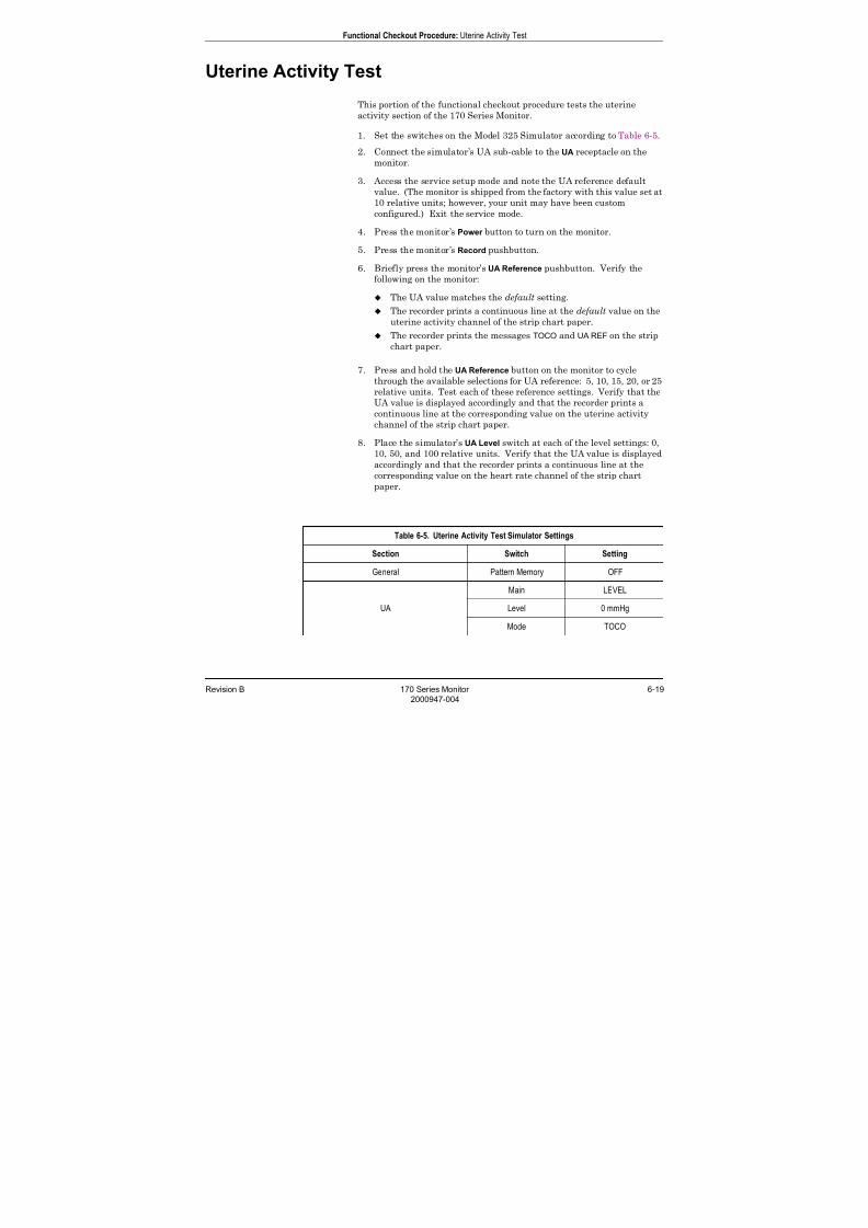
7/25/2019 Serv. Corometrics 170
http://slidepdf.com/reader/full/serv-corometrics-170 119/254
Revision B 170 Series Monitor 6-19
2000947-004
Functional Checkout Procedure: Uterine Activity Test
Uterine Activity Test
This portion of the functional checkout procedure tests the uterine
activity section of the 170 Series Monitor.
1. Set the switches on the Model 325 Simulator according to Table 6-5.2. Connect the simulator’s UA sub-cable to the UA receptacle on the
monitor.
3. Access the service setup mode and note the UA reference default
value. (The monitor is shipped from the factory with this value set at
10 relative units; however, your unit may have been custom
configured.) Exit the service mode.
4. Press the monitor’s Power button to turn on the monitor.
5. Press the monitor’s Record pushbutton.
6. Briefly press the monitor’s UA Reference pushbutton. Verify the
following on the monitor:
The UA value matches the default setting.
The recorder prints a continuous line at the default value on the
uterine activity channel of the strip chart paper.
The recorder prints the messages TOCO and UA REF on the strip
chart paper.
7. Press and hold the UA Reference button on the monitor to cycle
through the available selections for UA reference: 5, 10, 15, 20, or 25
relative units. Test each of these reference settings. Verify that the
UA value is displayed accordingly and that the recorder prints a
continuous line at the corresponding value on the uterine activitychannel of the strip chart paper.
8. Place the simulator’s UA Level switch at each of the level settings: 0,
10, 50, and 100 relative units. Verify that the UA value is displayed
accordingly and that the recorder prints a continuous line at the
corresponding value on the heart rate channel of the strip chart
paper.
Table 6-5. Uterine Activity Test Simulator Settings
Section Switch Setting
General Pattern Memory OFF
UA
Main LEVEL
Level 0 mmHg
Mode TOCO
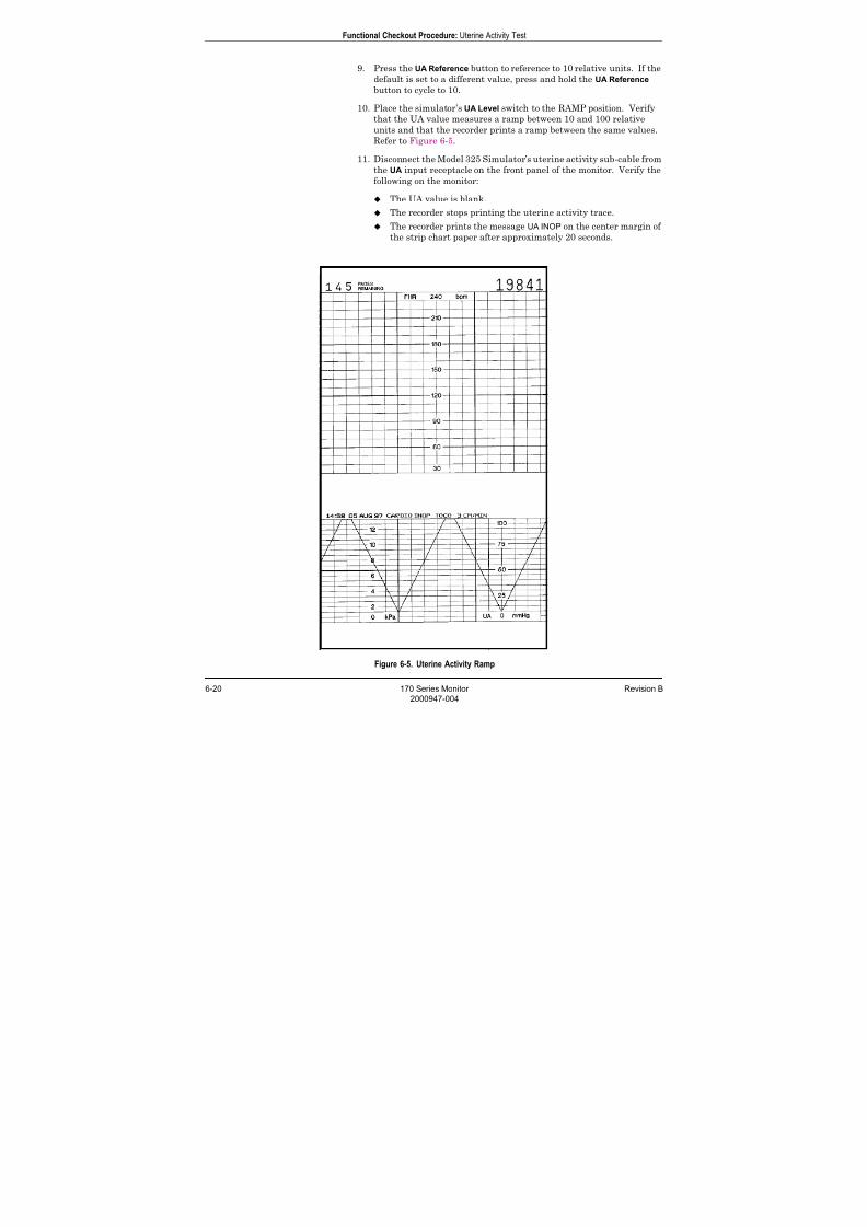
7/25/2019 Serv. Corometrics 170
http://slidepdf.com/reader/full/serv-corometrics-170 120/254
6-20 170 Series Monitor Revision B
2000947-004
Functional Checkout Procedure: Uterine Activity Test
9. Press the UA Reference button to reference to 10 relative units. If the
default is set to a different value, press and hold the UA Reference
button to cycle to 10.
10. Place the simulator’s UA Level switch to the RAMP position. Verify
that the UA value measures a ramp between 10 and 100 relative
units and that the recorder prints a ramp between the same values.
Refer to Figure 6-5.
11. Disconnect the Model 325 Simulator’s uterine activity sub-cable from
the UA input receptacle on the front panel of the monitor. Verify the
following on the monitor:
The UA value is blank.
The recorder stops printing the uterine activity trace.
The recorder prints the message UA INOP on the center margin of
the strip chart paper after approximately 20 seconds.
Figure 6-5. Uterine Activity Ramp
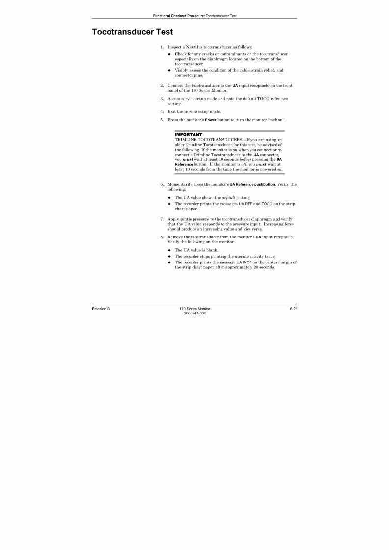
7/25/2019 Serv. Corometrics 170
http://slidepdf.com/reader/full/serv-corometrics-170 121/254
Revision B 170 Series Monitor 6-21
2000947-004
Functional Checkout Procedure: Tocotransducer Test
Tocotransducer Test
1. Inspect a Nautilus tocotransducer as follows:
Check for any cracks or contaminants on the tocotransducer
especially on the diaphragm located on the bottom of the
tocotransducer.
Visibly assess the condition of the cable, strain relief, and
connector pins.
2. Connect the tocotransducer to the UA input receptacle on the front
panel of the 170 Series Monitor.
3. Access service setup mode and note the default TOCO reference
setting.
4. Exit the service setup mode.
5. Press the monitor’s Power button to turn the monitor back on.
IMPORTANT
TRIMLINE TOCOTRANSDUCERS—If you are using an
older Trimline Tocotransducer for this test, be advised of
the following. If the monitor is on when you connect or re-
connect a Trimline Tocotransducer to the UA connector,
you must wait at least 10 seconds before pressing the UA
Reference button. If the monitor is off , you must wait at
least 10 seconds from the time the monitor is powered on.
6. Momentarily press the monitor’s UA Reference pushbutton. Verify thefollowing:
The UA value shows the default setting.
The recorder prints the messages UA REF and TOCO on the strip
chart paper.
7. Apply gentle pressure to the tocotransducer diaphragm and verify
that the UA value responds to the pressure input. Increasing force
should produce an increasing value and vice versa.
8. Remove the tocotransducer from the monitor’s UA input receptacle.
Verify the following on the monitor:
The UA value is blank.
The recorder stops printing the uterine activity trace.
The recorder prints the message UA INOP on the center margin of
the strip chart paper after approximately 20 seconds.
7/25/2019 Serv. Corometrics 170
http://slidepdf.com/reader/full/serv-corometrics-170 122/254
6-22 170 Series Monitor Revision B
2000947-004
Functional Checkout Procedure: Strain Gauge Transducer Test
Strain Gauge Transducer Test
1. Inspect a strain gauge as follows:
Unscrew the plastic dome from the transducer and check for any
cracks or contaminants on the transducer.
Visibly assess the condition of the cable, strain relief, and the
connector pins.
2. Connect the strain gauge to the UA input receptacle on the front panel
of the monitor. Verify the following on the monitor:
The UA value may read negative numbers indicating baseline
pressure is off scale. In this case, the message BASELINE PRESSURE
OFF SCALE prints on the strip chart paper.
After approximately 20 seconds, the message IUP prints on the
center margin of the strip chart paper.
3. Select the monitor’s UA Reference button and verify the following on themonitor:
The UA value is 0 mmHg.
The UA trend is a continuous line at 0 mmHg on the strip chart
paper.
The message UA REF prints on the strip chart paper.
4. Apply gentle pressure on the strain gauge diaphragm and verify that
the UA value and trend respond to the input. Increasing force should
produce an increasing value and vice versa.
5. Disconnect the strain gauge from the front panel of the monitor.
Verify the following on the monitor:
The UA value is blank.
The UA trend stops plotting on the strip chart paper.
After approximately 20 seconds, the message UA INOP prints on
the strip chart paper.
7/25/2019 Serv. Corometrics 170
http://slidepdf.com/reader/full/serv-corometrics-170 123/254
Revision B 170 Series Monitor 6-23
2000947-004
Functional Checkout Procedure: Pattern Memory Test
Pattern Memory Test
The pattern memory of the simulator can be used to test any of the
following mode combinations of the monitor.
FECG/TOCO FECG/IUP
US/TOCO or US2/TOCO
US/IUP or US2/IUP
US/FMD/TOCO
US/FMD/IUP
FECG/US/TOCO
FECG/US/IUP
NOTE US/US2 cannot be tested simultaneously unless two Model 325
Simulators or two ultrasound transducers are used. Do not
attempt to test dual ultrasound using one Model 325 Simulatorand one ultrasound transducer or a conflict between enable lines
will occur.
NOTE Although dual heart rate can be verified using the pattern
memory, an additional procedure is given in this functional
checkout procedure.
To check any of the mode combinations listed above:
1. Connect the appropriate simulator sub-cables to the corresponding
receptacles on the monitor.
2. Enable the modes on the simulator.
3. Set the simulator’s Pattern Memory switch to the ON position.
4. If not already on, press the monitor’s Record pushbutton.
5. Verify the following on the monitor:
Each heart rate display (FHR1 and FHR2) responds accordingly
for value and heartbeat indicator.
The UA display responds accordingly for the value.
The recorder responds appropriately in both trending and
message information.
NOTE
Refer to the “Model 325 Simulator Product Manual” forillustrations of the patterns to be expected on the monitor.
7/25/2019 Serv. Corometrics 170
http://slidepdf.com/reader/full/serv-corometrics-170 124/254
6-24 170 Series Monitor Revision B
2000947-004
Functional Checkout Procedure: Dual Heart Rate Test (Non-Pattern)
Dual Heart Rate Test (Non-Pattern)
FECG/US Modes
1. Connect the Model 325 Simulator’s ECG sub-cable to the monitor’s
FECG input receptacle.
2. Connect the simulator’s US sub-cable to the monitor’s US input
receptacle.
3. Set the switches on the Model 325 Simulator according to Table 6-6.
4. If not already on, select the monitor’s Record button.
5. Verify the following on the monitor:
The FHR1 value reads 120 BPM.
The FHR1 heartbeat indicator ( ) flashes at a rate of 120 times
per minute.
The FHR2 value varies between approximately 50 and 210 BPM.
The FHR2 heartbeat indicator ( ) flashes at a rate consistent
with the value.
The messages FECG and US print on the center margin of the strip
chart paper.
The FHR1 trend is a continuous plain black line ( ) on the
120 BPM mark on the top grid of the strip chart paper. (Refer to
Figure 6-6.)
The FHR2 trend is a bold black ramp trace ( ) between 50
and 210 BPM on the top grid of the strip chart paper. (Refer to
Figure 6-6.)

7/25/2019 Serv. Corometrics 170
http://slidepdf.com/reader/full/serv-corometrics-170 125/254
Revision B 170 Series Monitor 6-25
2000947-004
Functional Checkout Procedure: Dual Heart Rate Test (Non-Pattern)
Table 6-6. Model 325 Simulator Settings for FECG/US Test
Section Switch Setting
FECG/MECG
Main RATE
Rate 120 BPM
Mode FECG
QRS Amplitude 50 µV
QRS Polarity +
ULTRASOUND/FMD
Mode US
Level MED
Rate RAMP
General Pattern Memory OFF
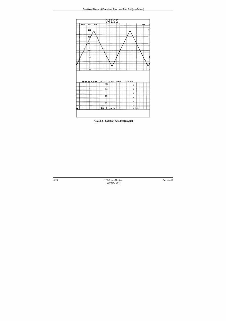
7/25/2019 Serv. Corometrics 170
http://slidepdf.com/reader/full/serv-corometrics-170 126/254
6-26 170 Series Monitor Revision B
2000947-004
Functional Checkout Procedure: Dual Heart Rate Test (Non-Pattern)
Figure 6-6. Dual Heart Rate, FECG and US
7/25/2019 Serv. Corometrics 170
http://slidepdf.com/reader/full/serv-corometrics-170 127/254
Revision B 170 Series Monitor 6-27
2000947-004
Functional Checkout Procedure: Dual Heart Rate Test (Non-Pattern)
Dual Ultrasound Modes
As stated previously, the dual ultrasound mode of the 170 Series Monitor
cannot be tested unless two Model 325 Simulators are used or two
Nautilus ultrasound transducers. Do not attempt to test dual
ultrasound using one Model 325 Simulator and one ultrasound
transducer. This procedure details using two transducers since it is morepractical for a test site.
1. If not already on, press the monitor’s Record pushbutton.
2. Plug one ultrasound transducer into the monitor’s US input
receptacle and the other into the monitor’s US2 receptacle. Verify the
following on the monitor:
The FHR1 value shows three steady dashes “– – –.”
The FHR2 value shows three steady dashes “– – –.”
The recorder prints the messages US and US2 on the center
margin of the strip chart paper.
3. Use your finger to rub the face of the ultrasound transducer
connected to the monitor’s US input receptacle; try to maintain a
steady rate and verify the following on the monitor:
The FHR1 value responds to the rubbing.
The FHR1 heartbeat indicator ( ) responds to the input.
The recorder prints the heart rate tracing corresponding to the
rate and the trace is plain black ( ).
4. Use your finger to rub the face of the ultrasound transducer
connected to the monitor’s US2 input receptacle; try to maintain a
steady rate and verify the following on the monitor:
The FHR2 value responds to the rubbing.
The FHR2 heartbeat indicator ( ) responds to the input.
The recorder prints the heart rate tracing corresponding to the
rate and the trace is bold black ( ).
7/25/2019 Serv. Corometrics 170
http://slidepdf.com/reader/full/serv-corometrics-170 128/254
6-28 170 Series Monitor Revision B
2000947-004
Functional Checkout Procedure: Alarm Test
Alarm Test
This portion of the test ensures the integrity of the audio alarms and
tests the alarm limit software.
1. Connect the Model 325 Simulator’s US sub-cable to the monitor’s US input.
2. Press and hold (for three seconds) Setup to enter the monitor’s setup
mode.
3. Set the FHR alarm enable to on.
4. Set the FHR high alarm limit value to 180 BPM.
5. Set the FHR low alarm limit value to 100 BPM.
6. Set the FHR audio alarm to a level you can easily hear.
7. Press the Setup button to exit the setup mode.
8. Press the monitor’s Record button.
9. Verify that the FHR high and low limits print in the annotation area
of the strip chart paper.
10. Turn off the monitor’s recorder.
11. Set the switches on the Model 325 Input Simulator according to
Table 6-7.
12. Using the simulator’s Manual Adjustment knob, input an US signal of
179 BPM as indicated on the monitor. Verify that there is no alarm
tone sounding from the monitor’s speaker.
13. Using the simulator’s Manual Adjustment knob, increase the US rateto 180 BPM. Again, verify that there is no alarm tone sounding from
the monitor’s speaker.
14. Using the simulator’s Manual Adjustment knob, increase the US rate
to 181 BPM. After five minutes, verify the following on the monitor:
An alarm tone is emitted from the monitor’s speaker (alternating
high/low tones).
The Alarm indicator flashes.
The affected heart rate numerics flash.
15. Press the monitor’s front panel Alarm Silence pushbutton and verify
that the alarm tone silences but the visual indications remain
present.
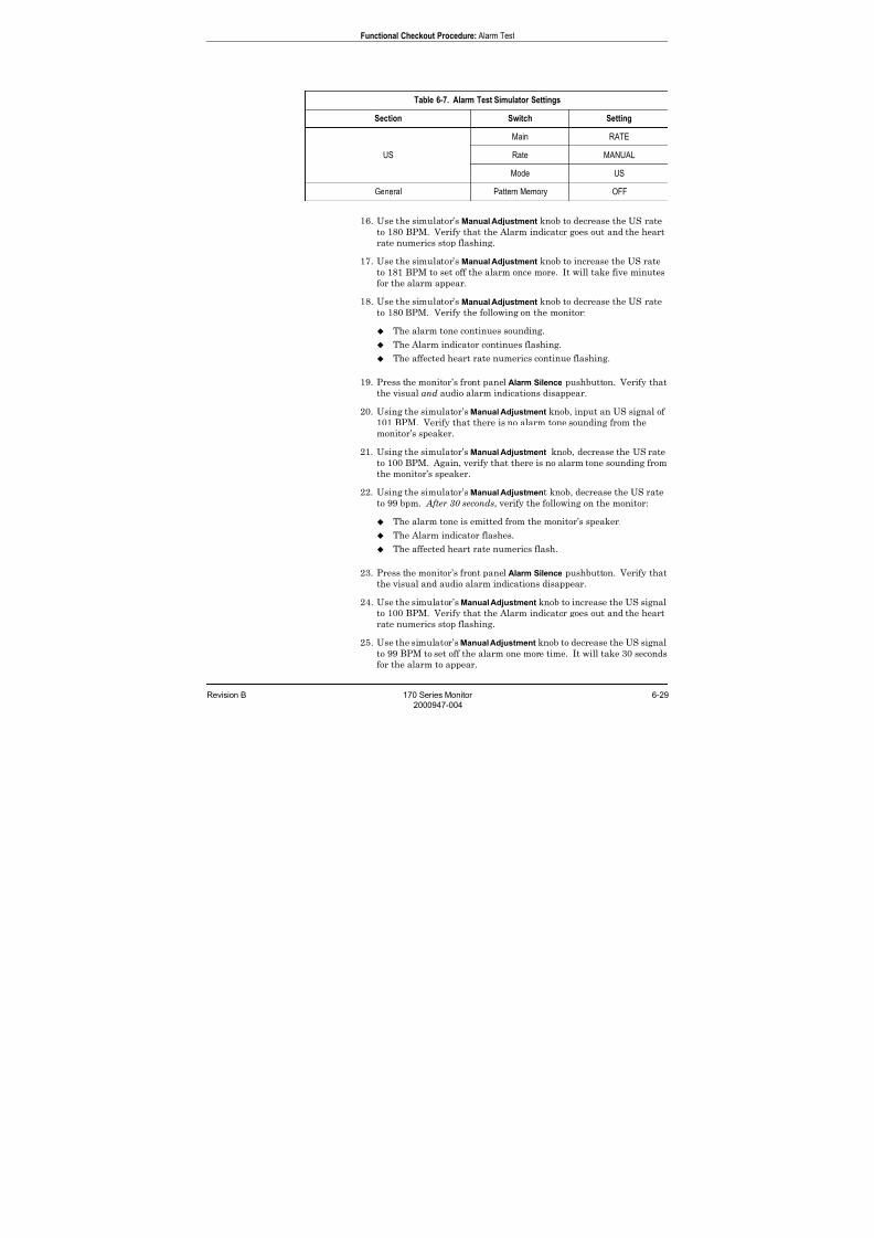
7/25/2019 Serv. Corometrics 170
http://slidepdf.com/reader/full/serv-corometrics-170 129/254
Revision B 170 Series Monitor 6-29
2000947-004
Functional Checkout Procedure: Alarm Test
16. Use the simulator’s Manual Adjustment knob to decrease the US rate
to 180 BPM. Verify that the Alarm indicator goes out and the heart
rate numerics stop flashing.
17. Use the simulator’s Manual Adjustment knob to increase the US rate
to 181 BPM to set off the alarm once more. It will take five minutes
for the alarm appear.
18. Use the simulator’s Manual Adjustment knob to decrease the US rate
to 180 BPM. Verify the following on the monitor:
The alarm tone continues sounding.
The Alarm indicator continues flashing.
The affected heart rate numerics continue flashing.
19. Press the monitor’s front panel Alarm Silence pushbutton. Verify that
the visual and audio alarm indications disappear.
20. Using the simulator’s Manual Adjustment knob, input an US signal of
101 BPM. Verify that there is no alarm tone sounding from themonitor’s speaker.
21. Using the simulator’s Manual Adjustment knob, decrease the US rate
to 100 BPM. Again, verify that there is no alarm tone sounding from
the monitor’s speaker.
22. Using the simulator’s Manual Adjustment knob, decrease the US rate
to 99 bpm. After 30 seconds, verify the following on the monitor:
The alarm tone is emitted from the monitor’s speaker.
The Alarm indicator flashes.
The affected heart rate numerics flash.
23. Press the monitor’s front panel Alarm Silence pushbutton. Verify that
the visual and audio alarm indications disappear.
24. Use the simulator’s Manual Adjustment knob to increase the US signal
to 100 BPM. Verify that the Alarm indicator goes out and the heart
rate numerics stop flashing.
25. Use the simulator’s Manual Adjustment knob to decrease the US signal
to 99 BPM to set off the alarm one more time. It will take 30 seconds
for the alarm to appear.
Table 6-7. Alarm Test Simulator Settings
Section Switch Setting
US
Main RATE
Rate MANUAL
Mode US
General Pattern Memory OFF
7/25/2019 Serv. Corometrics 170
http://slidepdf.com/reader/full/serv-corometrics-170 130/254
6-30 170 Series Monitor Revision B
2000947-004
Functional Checkout Procedure: Alarm Test
26. Use the simulator’s Manual Adjustment knob to increase the US signal
to 100 bpm. Verify the following on the monitor:
The alarm tone continues sounding.
The Alarm indicator stops continues flashing.
The affected heart rate numerics continue flashing.
27. Press the monitor’s front panel Alarm Silence pushbutton. Verify that
the visual and audio alarm indications disappear.
28. This concludes the functional checkout procedure.
7/25/2019 Serv. Corometrics 170
http://slidepdf.com/reader/full/serv-corometrics-170 131/254
Revision B 170 Series Monitor 7-1
2000947-004
Chapter 7
Serviceable Assemblies7This chapter provides information to aid in performing routine service
and maintenance on a 170 Series Monitor. This section of the manual is
not intended as a substitute for proper professional training, or
familiarity with the 170 Series Monitor. Only qualified service personnel
should attempt servicing a 170 Series Monitor.
This chapter contains the following information:
General Anti-Static Handling Precautions. . . . . . . . . . . . . . . . 7-2
Transducer Plug Replacement Kits . . . . . . . . . . . . . . . . . . . . . 7-3
Nautilus Transducer Cable Replacement . . . . . . . . . . . . . . . . 7-15
Removing the Monitor Top Cover . . . . . . . . . . . . . . . . . . . . . . 7-19
Tocotransducer Calibration . . . . . . . . . . . . . . . . . . . . . . . . . . . 7-20
Nautilus Ultrasound Transducer Top Cover Replacement . . 7-30
Nautilus Transducer Reassembly . . . . . . . . . . . . . . . . . . . . . . 7-32
Testing a Repaired Transducer (TOCO or US). . . . . . . . . . . . 7-34
Replacing the Main Board . . . . . . . . . . . . . . . . . . . . . . . . . . . . 7-35
Replacing the Membrane Switch Panel . . . . . . . . . . . . . . . . . 7-37
Replacing a Front Panel Connector . . . . . . . . . . . . . . . . . . . . 7-40
Servicing the Recorder . . . . . . . . . . . . . . . . . . . . . . . . . . . . . . . 7-41
7/25/2019 Serv. Corometrics 170
http://slidepdf.com/reader/full/serv-corometrics-170 132/254
7-2 170 Series Monitor Revision B
2000947-004
Serviceable Assemblies: General Anti-Static Handling Precautions
General Anti-Static Handling Precautions
The following guidelines should be followed when handling circuit boards
or assemblies containing circuit boards. Following these procedures
helps resist damage that can be caused by static electricity.
Discharge any static charge you may have built up before
handling parts.
Wear a grounded, anti-static wristband at all times.
Use a static-free work surface.
Store items in anti-static bags or boxes.
Do not remove items from anti-static containers until needed.
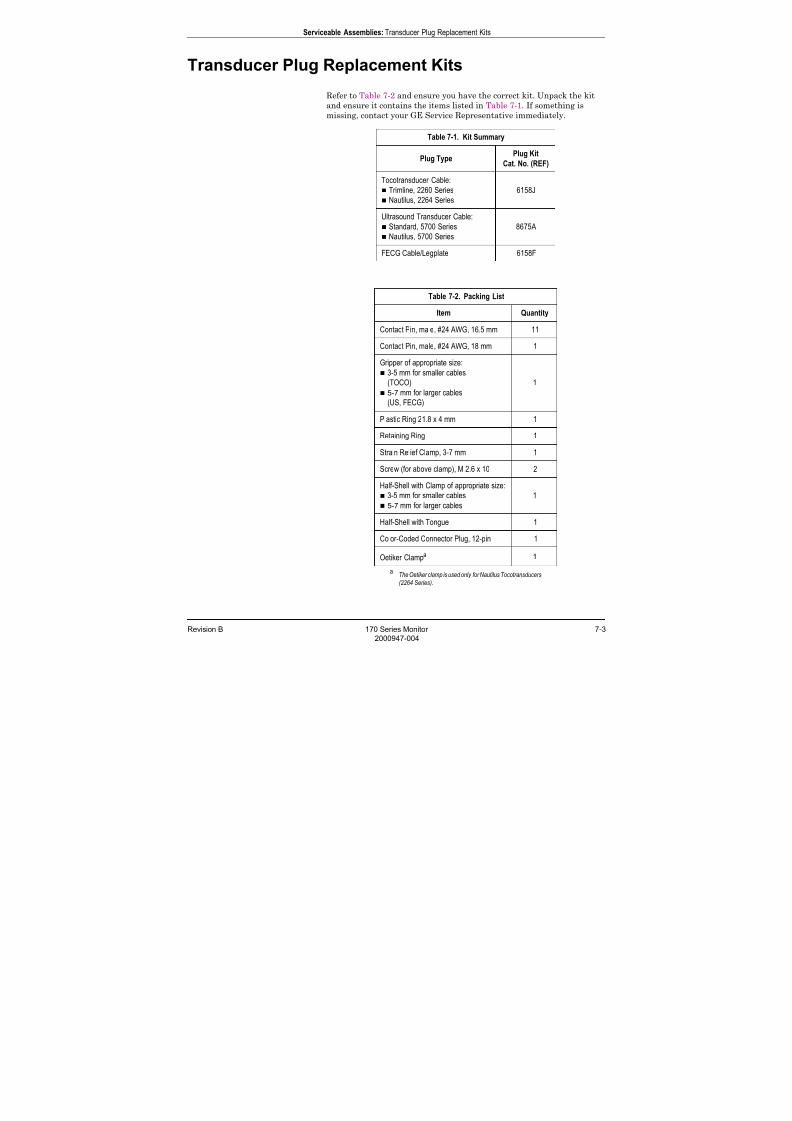
7/25/2019 Serv. Corometrics 170
http://slidepdf.com/reader/full/serv-corometrics-170 133/254
Revision B 170 Series Monitor 7-3
2000947-004
Serviceable Assemblies: Transducer Plug Replacement Kits
Transducer Plug Replacement Kits
Refer to Table 7-2 and ensure you have the correct kit. Unpack the kit
and ensure it contains the items listed in Table 7-1. If something is
missing, contact your GE Service Representative immediately.
Table 7-1. Kit Summary
Plug TypePlug Kit
Cat. No. (REF)
Tocotransducer Cable:
Trimline, 2260 Series
Nautilus, 2264 Series
6158J
Ultrasound Transducer Cable:
Standard, 5700 Series
Nautilus, 5700 Series
8675A
FECG Cable/Legplate 6158F
Table 7-2. Packing List
Item Quantity
Contact Pin, male, #24 AWG, 16.5 mm 11
Contact Pin, male, #24 AWG, 18 mm 1
Gripper of appropriate size:
3-5 mm for smaller cables
(TOCO) 5-7 mm for larger cables
(US, FECG)
1
Plastic Ring 21.8 x 4 mm 1
Retaining Ring 1
Strain Relief Clamp, 3-7 mm 1
Screw (for above clamp), M 2.6 x 10 2
Half-Shell with Clamp of appropriate size:
3-5 mm for smaller cables
5-7 mm for larger cables
1
Half-Shell with Tongue 1
Color-Coded Connector Plug, 12-pin 1
Oetiker Clampa
aThe Oetiker clamp is used only for Nautilus Tocotransducers
(2264 Series).
1
7/25/2019 Serv. Corometrics 170
http://slidepdf.com/reader/full/serv-corometrics-170 134/254
7-4 170 Series Monitor Revision B
2000947-004
Serviceable Assemblies: Transducer Plug Replacement Kits
Handling Precautions
Transducers are delicate measuring instruments and must be handled
accordingly. Transducer damage can be avoided by taking the following
precautions:
Avoid banging or dropping transducers. Refrain from wrapping transducer cables around transducer body.
Do not immerse transducers in aqueous cleaning solutions.
Do not pull on cables when removing transducer plugs from the
monitor front-panel connectors; remove plugs by grasping the
gripper.
Equipment Required
You will need the following equipment:
Green
1
Stranded Wire (approximately 6 inches) #24 AWG for tocotransducers and ultrasound transducers
#26 AWG for FECG cable/legplates
#26 AWG Blue Stranded Wire (approximately 4 inches) for FECG
Cable
Wire Cutter/Stripper
Soldering Iron and Solder
Shrink Tubing
Oetiker Pincers (for Nautilus Tocotransducers only)2
1The color green is specified for consistency with factory builds and the wiring charts
contained in this document. 2
This tool is required to place an Oetiker clamp on a 2264 Series Nautilus Tocotransducer.
You can order the Standard Pincers (No. 1098) or Side Jaw Pincers (No. 1099) from
Oetiker, Inc., P.O. Box 93, Livingston, NJ 07039. The telephone number is: 201-992-1920.
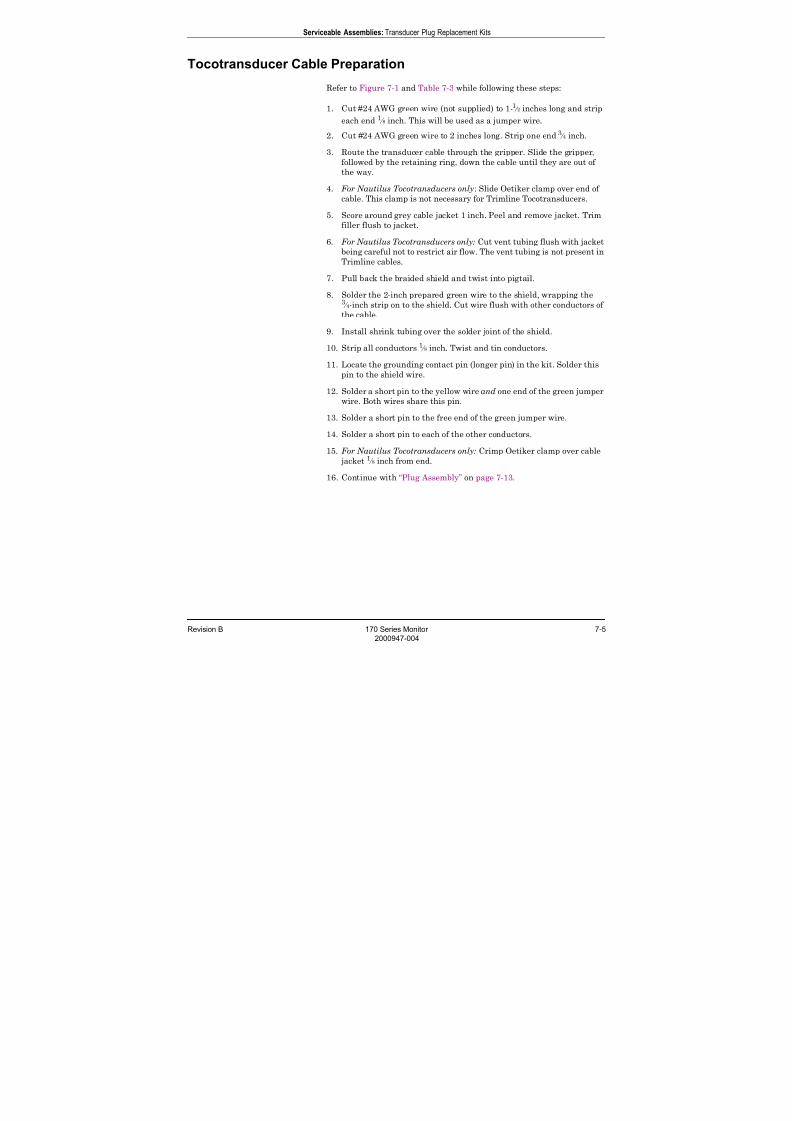
7/25/2019 Serv. Corometrics 170
http://slidepdf.com/reader/full/serv-corometrics-170 135/254
Revision B 170 Series Monitor 7-5
2000947-004
Serviceable Assemblies: Transducer Plug Replacement Kits
Tocotransducer Cable Preparation
Refer to Figure 7-1 and Table 7-3 while following these steps:
1. Cut #24 AWG green wire (not supplied) to 1-1 ⁄ 2 inches long and strip
each end 1 ⁄ 8 inch. This will be used as a jumper wire.
2. Cut #24 AWG green wire to 2 inches long. Strip one end 3 ⁄ 4 inch.
3. Route the transducer cable through the gripper. Slide the gripper,
followed by the retaining ring, down the cable until they are out of
the way.
4. For Nautilus Tocotransducers only: Slide Oetiker clamp over end of
cable. This clamp is not necessary for Trimline Tocotransducers.
5. Score around grey cable jacket 1 inch. Peel and remove jacket. Trim
filler flush to jacket.
6. For Nautilus Tocotransducers only: Cut vent tubing flush with jacket
being careful not to restrict air flow. The vent tubing is not present inTrimline cables.
7. Pull back the braided shield and twist into pigtail.
8. Solder the 2-inch prepared green wire to the shield, wrapping the3 ⁄ 4-inch strip on to the shield. Cut wire flush with other conductors of
the cable.
9. Install shrink tubing over the solder joint of the shield.
10. Strip all conductors 1 ⁄ 8 inch. Twist and tin conductors.
11. Locate the grounding contact pin (longer pin) in the kit. Solder this
pin to the shield wire.
12. Solder a short pin to the yellow wire and one end of the green jumper
wire. Both wires share this pin.
13. Solder a short pin to the free end of the green jumper wire.
14. Solder a short pin to each of the other conductors.
15. For Nautilus Tocotransducers only: Crimp Oetiker clamp over cable
jacket 1 ⁄ 8 inch from end.
16. Continue with “Plug Assembly” on page 7-13.
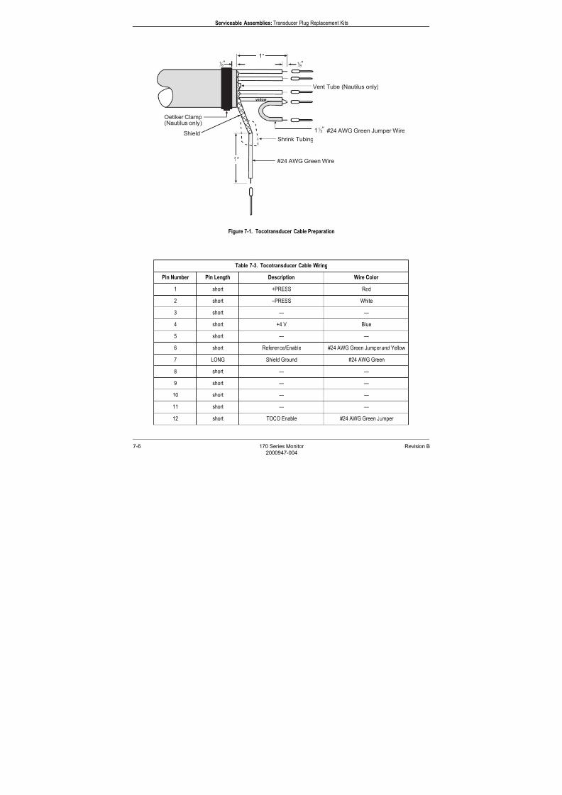
7/25/2019 Serv. Corometrics 170
http://slidepdf.com/reader/full/serv-corometrics-170 136/254
7-6 170 Series Monitor Revision B
2000947-004
Serviceable Assemblies: Transducer Plug Replacement Kits
Figure 7-1. Tocotransducer Cable Preparation
Table 7-3. Tocotransducer Cable Wiring
Pin Number Pin Length Description Wire Color
1 short +PRESS Red
2 short –PRESS White
3 short — —
4 short +4 V Blue
5 short — —
6 short Reference/Enable #24 AWG Green Jumper and Yellow
7 LONG Shield Ground #24 AWG Green
8 short — —
9 short — —
10 short — —
11 short — —
12 short TOCO Enable #24 AWG Green Jumper
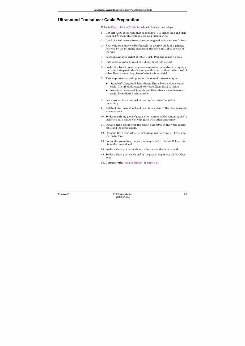
7/25/2019 Serv. Corometrics 170
http://slidepdf.com/reader/full/serv-corometrics-170 137/254
Revision B 170 Series Monitor 7-7
2000947-004
Serviceable Assemblies: Transducer Plug Replacement Kits
Ultrasound Transducer Cable Preparation
Refer to Figure 7-2 and Table 7-4 while following these steps:
1. Cut #24 AWG green wire (not supplied) to 1-1 ⁄ 2 inches long and strip
each end 1 ⁄ 8 inch. This will be used as a jumper wire.
2. Cut #24 AWG green wire to 4 inches long and strip each end 3 ⁄ 4 inch.
3. Route the transducer cable through the gripper. Slide the gripper,
followed by the retaining ring, down the cable until they are out of
the way.
4. Score around grey jacket of cable 1 inch. Peel and remove jacket.
5. Pull back the outer braided shield and twist into pigtail.
6. Solder the 4-inch prepared green wire to the outer shield, wrapping
the 3 ⁄ 4-inch strip onto shield. Cut wire flush with other conductor(s) of
cable. Retain remaining piece of wire for inner shield.
7. This step varies according to the ultrasound transducer type:
Standard Ultrasound Transducer: This cable is a dual-coaxial
cable. Cut off black coaxial cable and fillers flush to jacket.
Nautilus Ultrasound Transducer: This cable is a single-coaxial
cable. Trim fillers flush to jacket.
8. Score around the white jacket leaving 3 ⁄ 16 inch of the jacket
remaining.
9. Pull back the inner shield and twist into a pigtail. The clear dielectric
is now exposed.
10. Solder remaining piece of green wire to inner shield, wrapping the3
⁄ 4 inch strip onto shield. Cut wire flush with other conductors.
11. Install shrink tubing over the solder joint between the white coaxial
cable and the inner shield.
12. Strip the three conductors 1 ⁄ 8 inch (clear and both green). Twist and
tin conductors.
13. Locate the grounding contact pin (longer pin) in the kit. Solder this
pin to the inner shield.
14. Solder a short pin to the clear conductor and the outer shield.
15. Solder a short pin to each end of the green jumper wire (1-1 ⁄ 2 inches
long).
16. Continue with “Plug Assembly” on page 7-13.

7/25/2019 Serv. Corometrics 170
http://slidepdf.com/reader/full/serv-corometrics-170 138/254
7-8 170 Series Monitor Revision B
2000947-004
Serviceable Assemblies: Transducer Plug Replacement Kits
Figure 7-2. Ultrasound Transducer Cable Preparation
Score around length of jacket 1inch. Peel
jacket and remove.
Separate outer braided shield and twist.
For Standard ultrasound transducers, the
cable is a dual coaxial cable.
For Nautilus ultrasound transducers, the
cable is a single coaxial cable.
If present, cut black coax and fillers flush
with grey jacket.
Solder #24 AWG green wire to outer shield.
Score around white jacket leaving 3 ⁄ 16 inch.
Separate inner braided shield and twist.
Solder #24 AWG green wire to inner shield.
Apply shrink tubing over clear wire and
solder joint of inner shield.
Strip conductors 1 ⁄ 8 inch. Twist and tin
conductors.
Solder contact pins to conductors and
jumper wire.
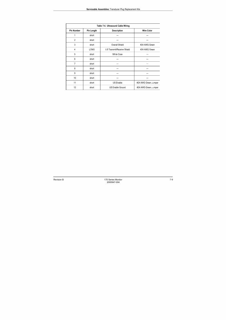
7/25/2019 Serv. Corometrics 170
http://slidepdf.com/reader/full/serv-corometrics-170 139/254
Revision B 170 Series Monitor 7-9
2000947-004
Serviceable Assemblies: Transducer Plug Replacement Kits
Table 7-4. Ultrasound Cable Wiring
Pin Number Pin Length Description Wire Color
1 short — —
2 short — —
3 short Overall Shield #24 AWG Green
4 LONG US Transmit/Receive Shield #24 AWG Green
5 short White Coax —
6 short — —
7 short — —
8 short — —
9 short — —
10 short — —
11 short US Enable #24 AWG Green Jumper
12 short US Enable Ground #24 AWG Green Jumper
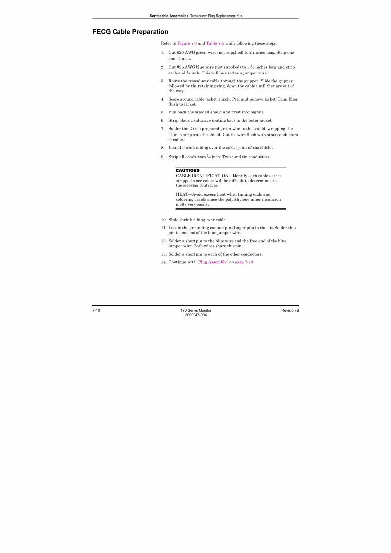
7/25/2019 Serv. Corometrics 170
http://slidepdf.com/reader/full/serv-corometrics-170 140/254
7-10 170 Series Monitor Revision B
2000947-004
Serviceable Assemblies: Transducer Plug Replacement Kits
FECG Cable Preparation
Refer to Figure 7-3 and Table 7-5 while following these steps:
1. Cut #26 AWG green wire (not supplied) to 2 inches long. Strip one
end 3 ⁄ 4 inch.
2. Cut #26 AWG blue wire (not supplied) to 1-1 ⁄ 2 inches long and strip
each end 1 ⁄ 8 inch. This will be used as a jumper wire.
3. Route the transducer cable through the gripper. Slide the gripper,
followed by the retaining ring, down the cable until they are out of
the way.
4. Score around cable jacket 1 inch. Peel and remove jacket. Trim filler
flush to jacket.
5. Pull back the braided shield and twist into pigtail.
6. Strip black conductive coating back to the outer jacket.
7. Solder the 2-inch prepared green wire to the shield, wrapping the3 ⁄ 4-inch strip onto the shield. Cut the wire flush with other conductors
of cable.
8. Install shrink tubing over the solder joint of the shield.
9. Strip all conductors 1 ⁄ 8 inch. Twist and tin conductors.
CAUTIONS
CABLE IDENTIFICATION—Identify each cable as it is
stripped since colors will be difficult to determine once
the sleeving contracts.
HEAT—Avoid excess heat when tinning ends and
soldering braids since the polyethylene inner insulation
melts very easily.
10. Slide shrink tubing over cable.
11. Locate the grounding contact pin (longer pin) in the kit. Solder this
pin to one end of the blue jumper wire.
12. Solder a short pin to the blue wire and the free end of the blue
jumper wire. Both wires share this pin.
13. Solder a short pin to each of the other conductors,
14. Continue with “Plug Assembly” on page 7-13.
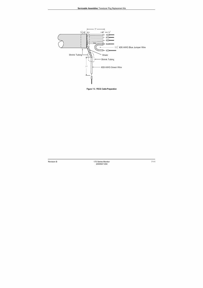
7/25/2019 Serv. Corometrics 170
http://slidepdf.com/reader/full/serv-corometrics-170 141/254
Revision B 170 Series Monitor 7-11
2000947-004
Serviceable Assemblies: Transducer Plug Replacement Kits
Figure 7-3. FECG Cable Preparation
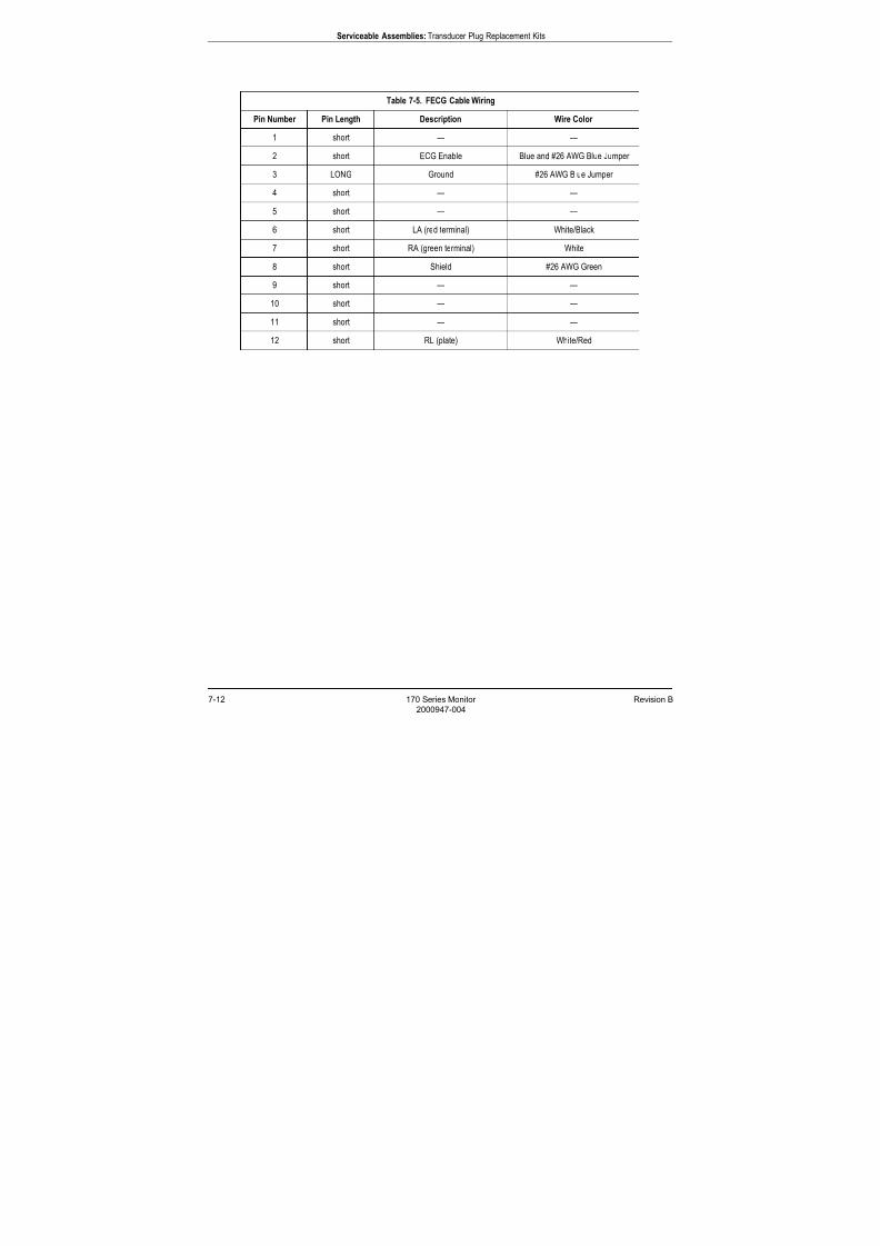
7/25/2019 Serv. Corometrics 170
http://slidepdf.com/reader/full/serv-corometrics-170 142/254
7-12 170 Series Monitor Revision B
2000947-004
Serviceable Assemblies: Transducer Plug Replacement Kits
Table 7-5. FECG Cable Wiring
Pin Number Pin Length Description Wire Color
1 short — —
2 short ECG Enable Blue and #26 AWG Blue Jumper
3 LONG Ground #26 AWG Blue Jumper
4 short — —
5 short — —
6 short LA (red terminal) White/Black
7 short RA (green terminal) White
8 short Shield #26 AWG Green
9 short — —
10 short — —
11 short — —
12 short RL (plate) White/Red
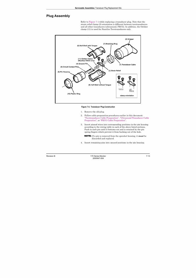
7/25/2019 Serv. Corometrics 170
http://slidepdf.com/reader/full/serv-corometrics-170 143/254
Revision B 170 Series Monitor 7-13
2000947-004
Serviceable Assemblies: Transducer Plug Replacement Kits
Plug Assembly
Refer to Figure 7-4 while replacing a transducer plug. Note that the
strain relief clamp (3) orientation is different between tocotransducers
and all other transducers (ultrasound, FECG). In addition, the Oetiker
clamp (11) is used for Nautilus Tocotransducers only.
Figure 7-4. Transducer Plug Construction
1. Remove the old plug.
2. Follow cable preparation procedures earlier in this document:
“Tocotransducer Cable Preparation”, “Ultrasound Transducer Cable
Preparation”, or “FECG Cable Preparation”.
3. Insert pinned wires into corresponding positions in the pin housing
according to the wiring table in each of the above listed sections.
Push in each pin until it bottoms out and is retained by the pin
spring fingers which prevent it from backing out of the hole.
NOTE If a pin is removed from the sprocket housing, it must be
discarded and replaced.
4. Insert remaining pins into unused positions in the pin housing.

7/25/2019 Serv. Corometrics 170
http://slidepdf.com/reader/full/serv-corometrics-170 144/254
7-14 170 Series Monitor Revision B
2000947-004
Serviceable Assemblies: Transducer Plug Replacement Kits
5. Insert the pin housing into the corresponding recess of the half-shell
(with strain-relief mounting holes). Position the housing so that the
two dots at the back are visible and at right angles to the plane of the
half-shell. Push the cable into the strain-relief slot. Ensure the slot
surrounds a portion of the cable with the outer covering intact.
6. Fasten the strain-relief clamp to the half-shell using the two metric
screws. Refer to inset of Figure 7-4.
Tocotransducer: the indent of the strain relief should
face outward.
Ultrasound and FECG Transducers: the indent of the strain
relief should face inward.
7. Place the half-shell (with tongue) on the pin housing, aligning it with
the two dots on the back of the housing. The half-shells should snap
together evenly. Slip the retaining ring over them to hold the
assembly together.
8. Slide the gripper back up the cable and align the two projections at
the rear of the plug assembly with the two recesses at the rear of thegripper.
NOTE Do not allow projections and recesses to become misaligned
while sliding the gripper onto the plug or the gripper will not
seat properly. Position the tongue opposite the gripper boot
through which the cable extends. This ensures that the cable
will extend downward once the plug is inserted into the
monitor.
CAUTION
KINKING—When sliding the gripper over the plug
assembly, pull the cable through the boot to prevent anykinking inside the gripper.
9. Install the plastic ring on the front of the plug.
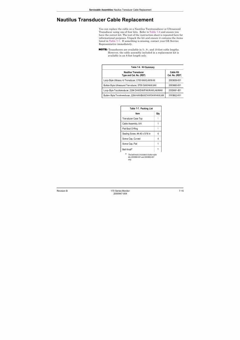
7/25/2019 Serv. Corometrics 170
http://slidepdf.com/reader/full/serv-corometrics-170 145/254
Revision B 170 Series Monitor 7-15
2000947-004
Serviceable Assemblies: Nautilus Transducer Cable Replacement
Nautilus Transducer Cable Replacement
You can replace the cable on a Nautilus Tocotransducer or Ultrasound
Transducer using one of four kits. Refer to Table 7-6 and ensure you
have the correct kit. The text of the instruction sheet is repeated here for
informational purposes. Unpack the kit and ensure it contains the itemslisted in Table 7-7. If something is missing, contact your GE Service
Representative immediately.
NOTE Transducers are available in 5-, 8-, and 10-foot cable lengths.
However, the cable assembly included in a replacement kit is
available in an 8-foot length only.
Table 7-6. Kit Summary
Nautilus Transducer
Type and Cat. No. (REF)
Cable Kit
Cat. No. (REF)
Loop-Style Ultrasound Transducer, 5700 KAX/LAX/MAX 2003659-001
Button-Style Ultrasound Transducer, 5700 GAX/HAX/JAX 2003660-001
Loop-Style Tocotransducer, 2264 DAX/EAX/FAX/KAX/LAX/MAX 2003661-001
Button-Style Tocotransducer, 2264 AAX/BAX/CAX/GAX/HAX/JAX 2003662-001
Table 7-7. Packing List
Item Qty
Transducer Case Top 1
Cable Assembly, 8-ft 1
Flat-Seal O-Ring 1
Sealing Screw, #4-40 x 5/16 in 6
Screw Cap, Curved 4
Screw Cap, Flat 1
Belt Knoba
a The belt knob is included in button-style
kits 2003660-001 and 2003662-001
only.
1
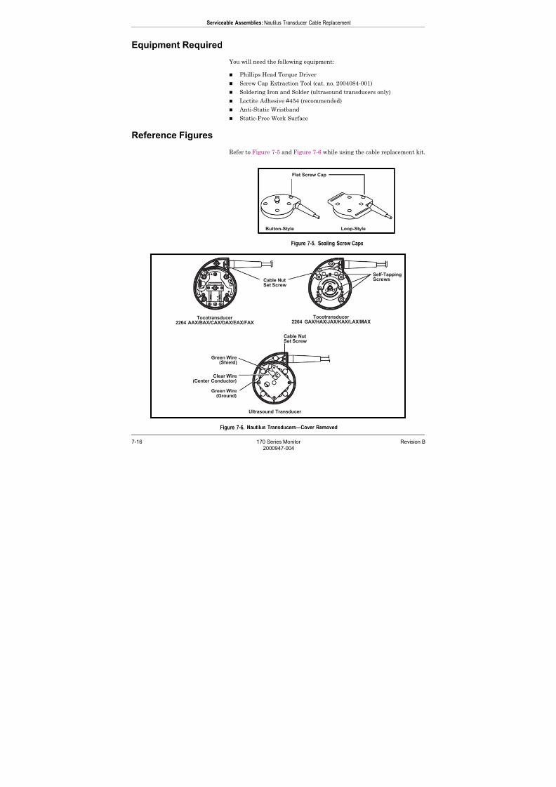
7/25/2019 Serv. Corometrics 170
http://slidepdf.com/reader/full/serv-corometrics-170 146/254
7-16 170 Series Monitor Revision B
2000947-004
Serviceable Assemblies: Nautilus Transducer Cable Replacement
Equipment Required
You will need the following equipment:
Phillips Head Torque Driver
Screw Cap Extraction Tool (cat. no. 2004084-001)
Soldering Iron and Solder (ultrasound transducers only)
Loctite Adhesive #454 (recommended)
Anti-Static Wristband
Static-Free Work Surface
Reference Figures
Refer to Figure 7-5 and Figure 7-6 while using the cable replacement kit.
Figure 7-5. Sealing Screw Caps
Figure 7-6. Nautilus Transducers—Cover Removed

7/25/2019 Serv. Corometrics 170
http://slidepdf.com/reader/full/serv-corometrics-170 147/254
Revision B 170 Series Monitor 7-17
2000947-004
Serviceable Assemblies: Nautilus Transducer Cable Replacement
Procedure
1. Unplug the transducer from the monitor or telemetry transmitter.
2. Use the screw cap extraction tool to pry off the five screw caps
(Figure 7-5). Discard all caps.
CAUTION
HANDLING–Take care not to damage the base sealing
groove.
3. Remove the five sealing screws and discard.
4. Remove the transducer cover and flat-seal o-ring. Discard both items.
5. Remove the cable connector according to the transducer type (Figure
7-6):
Tocotransducer
a. If the PC board header is on the underside of the board (2264
GAX/HAX/JAX/KAX/LAX/MAX only), remove the three self-
tapping screws from the board to gain access. Set aside screws.
b. Observe the orientation of the cable connector in the PC board
header, then unplug.
Ultrasound Transducer
a. Unscrew the green cable ground wire from the PC board. Set
aside screw.
b. Unsolder the green and clear cable wires from the PC board.
6. Loosen the cable nut set screw, then unscrew the cable from the cable
nut. Set aside screw and cable nut.
7. Remove the cable from the transducer base.
CAUTION
CABLE HANDLING–Do not place undue stress on cable
wires and shielding. Do not damage the cable o-ring or
the hole in the transducer base.
8. Feed the connector end of the new cable through the hole in thetransducer base. The cable o-ring should be seated in hole.

7/25/2019 Serv. Corometrics 170
http://slidepdf.com/reader/full/serv-corometrics-170 148/254
7-18 170 Series Monitor Revision B
2000947-004
Serviceable Assemblies: Nautilus Transducer Cable Replacement
9. Secure the molded strain relief end of the cable in the cable nut:
a. Place the flat side of the cable nut against the case base.
b. Rotate the cable assembly into the cable nut; continue threading
until the two are completely seated. Ensure the o-ring is seated
in the hole and one of the cable’s four set screw holes is centered
under the hole in the cable nut.c. Tighten the set screw until flush with the cable nut.
10. Connect cable according to transducer type (refer to Figure 7-6):
Tocotransducer
CAUTION
PRESSURE SENSITIVE BUTTON–Do not turn the
pressure sensitive button. Doing so will change the
button height and affect the tocotransducer calibration.
a. Plug the cable connector into the PC board header conforming to
the keying observed earlier.
b. If removed earlier, replace the PC board and tighten the three
self-tapping screws in the transducer base.
CAUTION
OVERTIGHTENING–Do not overtighten the screws.
Doing so could damage the threads in base.
Ultrasound Transducer
a. Solder the green and clear cable wires to the PC board (Figure 7-
6).
b. Replace and tighten the green ground wire on the PC board.
11. Install new flat-seal o-ring.
12. Nautilus Tocotransducers only: Prior to replacing the case top, it is
recommended that you calibrate the transducer. Refer to
“Tocotransducer Calibration” on page 7-20 prior to completing the
cable replacement procedure.
13. Follow the instructions for “Nautilus Transducer Reassembly” on
page 7-32.
7/25/2019 Serv. Corometrics 170
http://slidepdf.com/reader/full/serv-corometrics-170 149/254
Revision B 170 Series Monitor 7-19
2000947-004
Serviceable Assemblies: Removing the Monitor Top Cover
Removing the Monitor Top Cover
1. Unplug the AC adapter from the monitor to completely remove
power.
2. Remove the four bottom panel screws.
CAUTION
TOP COVER—The top cover remains tethered to the
main board via the display board and membrane
switch panel cables. Do not attempt to remove the
monitor cover without first disconnecting these cables.
3. Partially lift the top cover and slide it partways back to reveal the
cables connecting to the main board.
4. Disconnect the display board cable from J18 on the main board.5. Disconnect the membrane switch panel cable from J19 on the
main board.

7/25/2019 Serv. Corometrics 170
http://slidepdf.com/reader/full/serv-corometrics-170 150/254
7-20 170 Series Monitor Revision B
2000947-004
Serviceable Assemblies: Tocotransducer Calibration
Tocotransducer Calibration
Any of the following three transducers can be used with the 170 Series
Monitor:
Corometrics Nautilus Tocotransducer Corometrics Trimline Tocotransducer
Corometrics Large-Button Tocotransducer
Figure 7-7. CMR Test Jack
Table 7-8. CMR Test Jack Components
Part Description Catalog Number
Pressure Connector 6158J
475 Ω, 1/8 W, 1% Resistor 472127
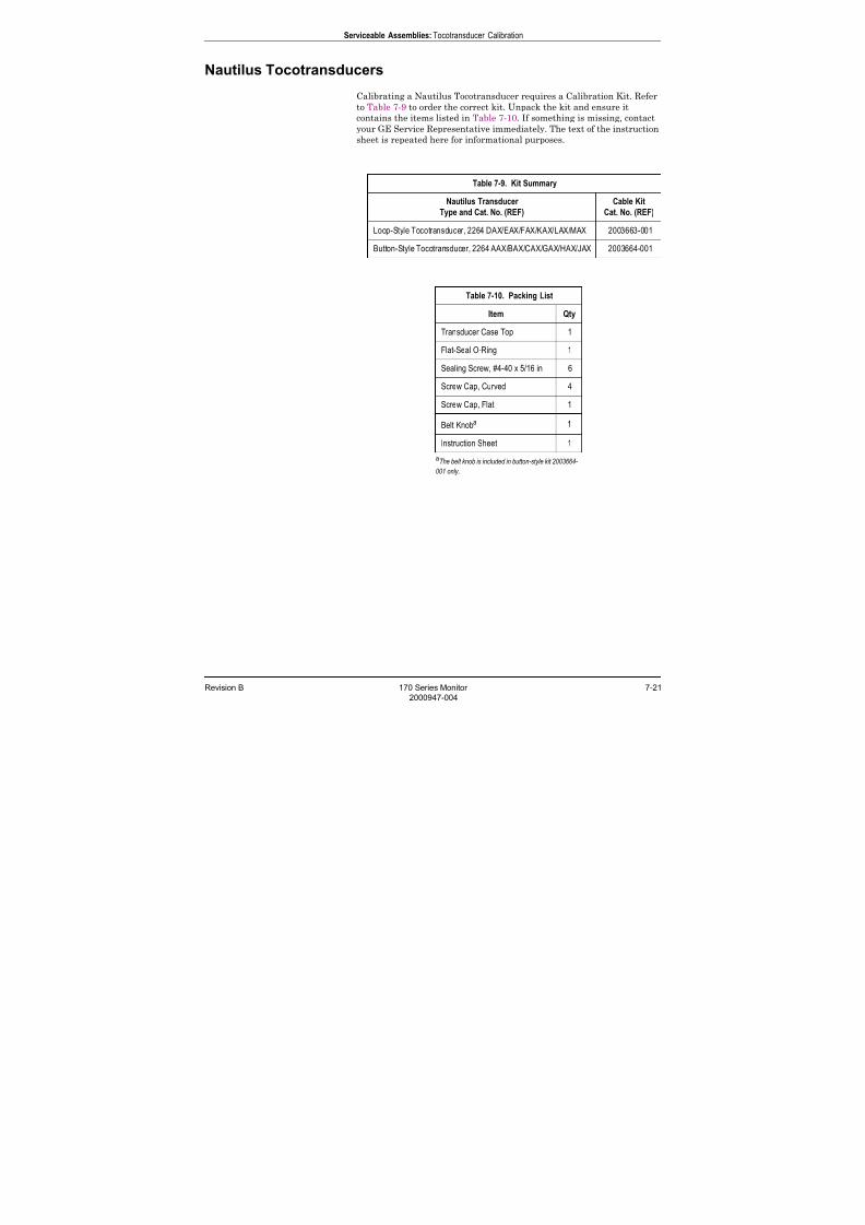
7/25/2019 Serv. Corometrics 170
http://slidepdf.com/reader/full/serv-corometrics-170 151/254
Revision B 170 Series Monitor 7-21
2000947-004
Serviceable Assemblies: Tocotransducer Calibration
Nautilus Tocotransducers
Calibrating a Nautilus Tocotransducer requires a Calibration Kit. Refer
to Table 7-9 to order the correct kit. Unpack the kit and ensure it
contains the items listed in Table 7-10. If something is missing, contact
your GE Service Representative immediately. The text of the instruction
sheet is repeated here for informational purposes.
Table 7-9. Kit Summary
Nautilus Transducer
Type and Cat. No. (REF)
Cable Kit
Cat. No. (REF)
Loop-Style Tocotransducer, 2264 DAX/EAX/FAX/KAX/LAX/MAX 2003663-001
Button-Style Tocotransducer, 2264 AAX/BAX/CAX/GAX/HAX/JAX 2003664-001
Table 7-10. Packing List
Item Qty
Transducer Case Top 1
Flat-Seal O-Ring 1
Sealing Screw, #4-40 x 5/16 in 6
Screw Cap, Curved 4
Screw Cap, Flat 1
Belt Knoba
aThe belt knob is included in button-style kit 2003664-
001 only.
1
Instruction Sheet 1
7/25/2019 Serv. Corometrics 170
http://slidepdf.com/reader/full/serv-corometrics-170 152/254
7-22 170 Series Monitor Revision B
2000947-004
Serviceable Assemblies: Tocotransducer Calibration
Equipment Required
IMPORTANT
WEIGHT TYPE—The specified weight, cat. no. (REF)
2003005-001, is designed specifically for testing Nautilus
Tocotransducers.
You will need the following equipment:
Phillips Head Torque Driver
Screw Cap Extraction Tool (cat. no. 2004084-001)
Digital Voltmeter: DM501 or equivalent with x1 probe or leads
Common Mode Rejection (CMR) Test Jack (Figure 7-7 and Table 7-8)
Potentiometer Adjustment Tool
52.5 gram Weight (cat. no. 2003005-001)
Torque Seal Loctite Adhesive #454 (recommended)
Anti-Static Wristband
Static-Free Work Surface
Calibrated 170 Series Monitor
Disassembly
CAUTION
HANDLING—Take care not to damage the transducer
base sealing groove.
1. Turn off the monitor.
2. Unplug the transducer from the monitor.
3. Use the screw cap extraction tool to pry off the five screw caps
(Figure 7-5). Discard all caps.
4. Remove the five sealing screws and discard.
5. Remove the transducer cover and flat-seal o-ring. Discard both items.
7/25/2019 Serv. Corometrics 170
http://slidepdf.com/reader/full/serv-corometrics-170 153/254
Revision B 170 Series Monitor 7-23
2000947-004
Serviceable Assemblies: Tocotransducer Calibration
Calibration for Cat. No. (REF) 2264 GAX/HAX/JAX/KAX/LAX/MAXRefer to Figure 7-6 during calibration.
1. Set the Gain (R11) and Offset (R6) potentiometers fully clockwise.
2. Connect the positive lead of the digital voltmeter to TP2 on the
Main Board; connect the negative lead to TP9.
3. Turn on the monitor.
4. Plug the CMR Test Jack into the monitor’s UA connector.
5. Measure the voltage across the test points and record the value.
6. Replace the CMR Test Jack with the transducer to be calibrated.
7. Place the tocotransducer on a flat surface so that the button is face
up, then center the 52.5 gram weight on the pressure sensitive
button.
8. Adjust the Offset (R6) potentiometer so that the voltage matches
the reading recorded in step 5 ± 0.04 V. This voltage is referred toas the “weight on” voltage.
9. Remove the weight and observe the voltage reading; this voltage is
referred to as the “weight off” voltage. A correctly adjusted
transducer will show a voltage change of +0.115 V ± 0.015 V. If the
change is less, adjust the Gain (R11) potentiometer
counterclockwise to increase the gain. If the change is more,
adjust the Gain (R11) potentiometer clockwise to decrease the
gain.
10. Repeat step 7 through step 9 until the change in voltage between
the “weight on” and “weight off” conditions falls into specification.
11. Torque seal all potentiometers.
12. Follow the instructions for “Nautilus Transducer Reassembly” on
page 7-32.
7/25/2019 Serv. Corometrics 170
http://slidepdf.com/reader/full/serv-corometrics-170 154/254
7-24 170 Series Monitor Revision B
2000947-004
Serviceable Assemblies: Tocotransducer Calibration
Calibration for Cat. No. (REF) 2264 AAX/BAX/CAX/DAX/EAX/FAXRefer to Figure 7-6 during calibration.
1. Set the Gain (R15) and Offset (R5) potentiometers fully
counterclockwise.
2. Set the Offset Trim (R6) potentiometer to its mid-position—
approximately six turns from fully counterclockwise.
3. Connect the positive lead of the digital voltmeter to TP2 on the
Main Board; connect the negative lead to TP9.
4. Turn on the monitor.
5. Plug the CMR Test Jack into the monitor’s UA connector.
6. Measure the voltage across the test points and record the value.
7. Replace the CMR Test Jack with the transducer to be calibrated.
8. Place the tocotransducer on a flat surface so that the button is face
up, then center the 52.5 gram weight on the pressure sensitive
button.
9. Adjust the Offset (R5) and Offset Trim (R6) potentiometers so that
the voltage matches the reading recorded in step 6 ± 0.04 V. This
voltage is referred to as the “weight on” voltage.
The Offset (R5) potentiometer provides course adjustment.
The Offset Trim (R6) potentiometer provides fine adjustment.
10. Remove the weight and observe the voltage reading; this voltage is
referred to as the “weight off” voltage. A correctly adjusted
transducer will show a voltage change of +0.115 V ± 0.015 V. If the
change is less, adjust the Gain (R15) potentiometercounterclockwise to increase the gain. If the change is more,
adjust the Gain (R15) potentiometer clockwise to decrease the
gain.
11. Repeat step 8 through step step 10 until the change in voltage
between the “weight on” and “weight off” conditions falls into
specification.
12. Torque seal all potentiometers.
13. Follow the instructions for “Nautilus Transducer Reassembly” on
page 7-32.

7/25/2019 Serv. Corometrics 170
http://slidepdf.com/reader/full/serv-corometrics-170 155/254
Revision B 170 Series Monitor 7-25
2000947-004
Serviceable Assemblies: Tocotransducer Calibration
Trimline Tocotransducers
The Corometrics Trimline Tocotransducer must be calibrated using the
following procedure for use with the 170 Series Monitor.
Equipment Required Digital voltmeter: DM501 or equivalent with x1 probe or leads
Common Mode Rejection (CMR) Test Jack (Refer to Figure 7-7
and Table 7-8.)
Calibrated 170 Series Monitor
Screwdriver or potentiometer adjustment tool
52.5 gram weight (cat. no. 13131AA)
Sealing tape (cat. no. 11043AA)
Torque seal
IMPORTANT
WEIGHT TYPE—The weight (cat. no. 13131AA) is
designed specifically for testing Trimline
tocotransducers. The weight’s bottom lip fits over the
transducer’s button.
ProcedureDuring this procedure, refer to Figure 7-8 for the location of
potentiometers in the Trimline tocotransducer.
Figure 7-8. Trimline Tocotransducer Potentiometer Locations

7/25/2019 Serv. Corometrics 170
http://slidepdf.com/reader/full/serv-corometrics-170 156/254
7-26 170 Series Monitor Revision B
2000947-004
Serviceable Assemblies: Tocotransducer Calibration
NOTE When performing this procedure, keep in mind that due to the
nature of the circuitry in the Trimline Tocotransducer, there is a
stabilization time of approximately two seconds for any output
voltage. After adjusting a potentiometer, verify that the output
has stabilized prior to taking a voltage reading.
1. Remove the nameplate and sealing tape from the top cover of the
Trimline Tocotransducer.
2. Set the GAIN and ZERO CTR potentiometers in the tocotransducer
fully counterclockwise.
3. Set the ZERO TRIM potentiometer to its mid-position—
approximately six turns from fully counterclockwise.
4. Locate TP2 and TP9 (ground) on the Main Board in the 170 Series
Monitor.
5. Connect the positive lead of the digital voltmeter to TP2; connect the
negative lead to TP9.
6. Apply power to the 170 Series Monitor; then plug the CMR Test Jackinto the monitor’s front panel uterine activity connector.
7. Measure the voltage at TP2 and record the value.
8. Replace the CMR Test Jack with the tocotransducer to be calibrated.
9. Place the tocotransducer on a flat surface so that the button is face
up, then center the 52.5 gram weight on the button.
10. Adjust the ZERO CTR and/or the ZERO TRIM potentiometer(s) so
that the voltage measured across TP2 and TP9 matches the reading
recorded in step 7, ± 0.04 V. This voltage is referred to as the
WEIGHT ON voltage.
The ZERO CTR potentiometer provides course adjustment.
The ZERO TRIM potentiometer provides fine adjustment.
11. Remove the weight and observe the voltage reading; this voltage is
referred to as the WEIGHT OFF voltage. A correctly adjusted
transducer will show a voltage change of +0.115 V ± 0.015 V from the
WEIGHT ON to WEIGHT OFF voltage. If the change is less than 0.1
V, adjust the GAIN potentiometer counterclockwise to increase the
gain. If the change is more than 0.13 V, then adjust the GAIN
potentiometer clockwise to decrease the gain.
12. Repeat step 9 through step 11 until the change in voltage between
the WEIGHT ON and WEIGHT OFF conditions falls intospecification.

7/25/2019 Serv. Corometrics 170
http://slidepdf.com/reader/full/serv-corometrics-170 157/254
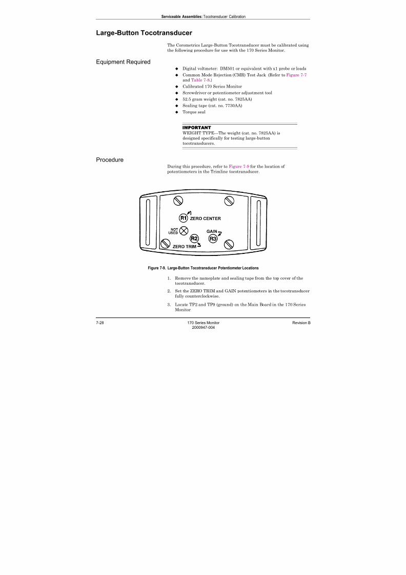
7/25/2019 Serv. Corometrics 170
http://slidepdf.com/reader/full/serv-corometrics-170 158/254
7-28 170 Series Monitor Revision B
2000947-004
Serviceable Assemblies: Tocotransducer Calibration
Large-Button Tocotransducer
The Corometrics Large-Button Tocotransducer must be calibrated using
the following procedure for use with the 170 Series Monitor.
Equipment Required Digital voltmeter: DM501 or equivalent with x1 probe or leads
Common Mode Rejection (CMR) Test Jack (Refer to Figure 7-7
and Table 7-8.)
Calibrated 170 Series Monitor
Screwdriver or potentiometer adjustment tool
52.5 gram weight (cat. no. 7825AA)
Sealing tape (cat. no. 7730AA)
Torque seal
IMPORTANT
WEIGHT TYPE—The weight (cat. no. 7825AA) is
designed specifically for testing large-button
tocotransducers.
ProcedureDuring this procedure, refer to Figure 7-9 for the location of
potentiometers in the Trimline tocotransducer.
Figure 7-9. Large-Button Tocotransducer Potentiometer Locations
1. Remove the nameplate and sealing tape from the top cover of the
tocotransducer.
2. Set the ZERO TRIM and GAIN potentiometers in the tocotransducer
fully counterclockwise.
3. Locate TP2 and TP9 (ground) on the Main Board in the 170 Series
Monitor.
7/25/2019 Serv. Corometrics 170
http://slidepdf.com/reader/full/serv-corometrics-170 159/254
Revision B 170 Series Monitor 7-29
2000947-004
Serviceable Assemblies: Tocotransducer Calibration
4. Connect the positive lead of the digital voltmeter to TP2; connect the
negative lead to TP9.
5. Apply power to the 170 Series Monitor; then plug the CMR Test Jack
into the monitor’s front panel uterine activity connector.
6. Measure the voltage at TP2 and record the value.
7. Replace the CMR Test Jack with the tocotransducer to be calibrated.
8. Place the tocotransducer on a flat surface so that the button is face
up, then center the 52.5 gram weight on the button.
9. Adjust the ZERO TRIM potentiometer so that the voltage measured
across TP2 and TP9 matches the reading recorded in step 6, ± 0.005
V. This voltage is referred to as the WEIGHT ON voltage.
NOTE If the ZERO TRIM potentiometer does not provide enough
adjustment, center the ZERO TRIM potentiometer and adjust
the ZERO CENTER potentiometer to match the reading recorded
in step 6, ± 1.0 V. then use the ZERO TRIM potentiometer to
match step 6, ± 0.005 mV.
10. Remove the weight and observe the voltage reading; this voltage is
referred to as the WEIGHT OFF voltage. A correctly adjusted
transducer will show a voltage change of +0.142 V ± 0.015 V from the
WEIGHT ON to WEIGHT OFF voltage. Use the GAIN
potentiometer to adjust the GAIN the gain.
11. Repeat step 8 to step 10 until the change in voltage between the
WEIGHT ON and WEIGHT OFF conditions falls into specification.
12. Torque seal all potentiometers. Affix new sealing tape and re-install
the nameplate.
13. Refer to “Testing a Repaired Transducer (TOCO or US)” onpage 7-34.
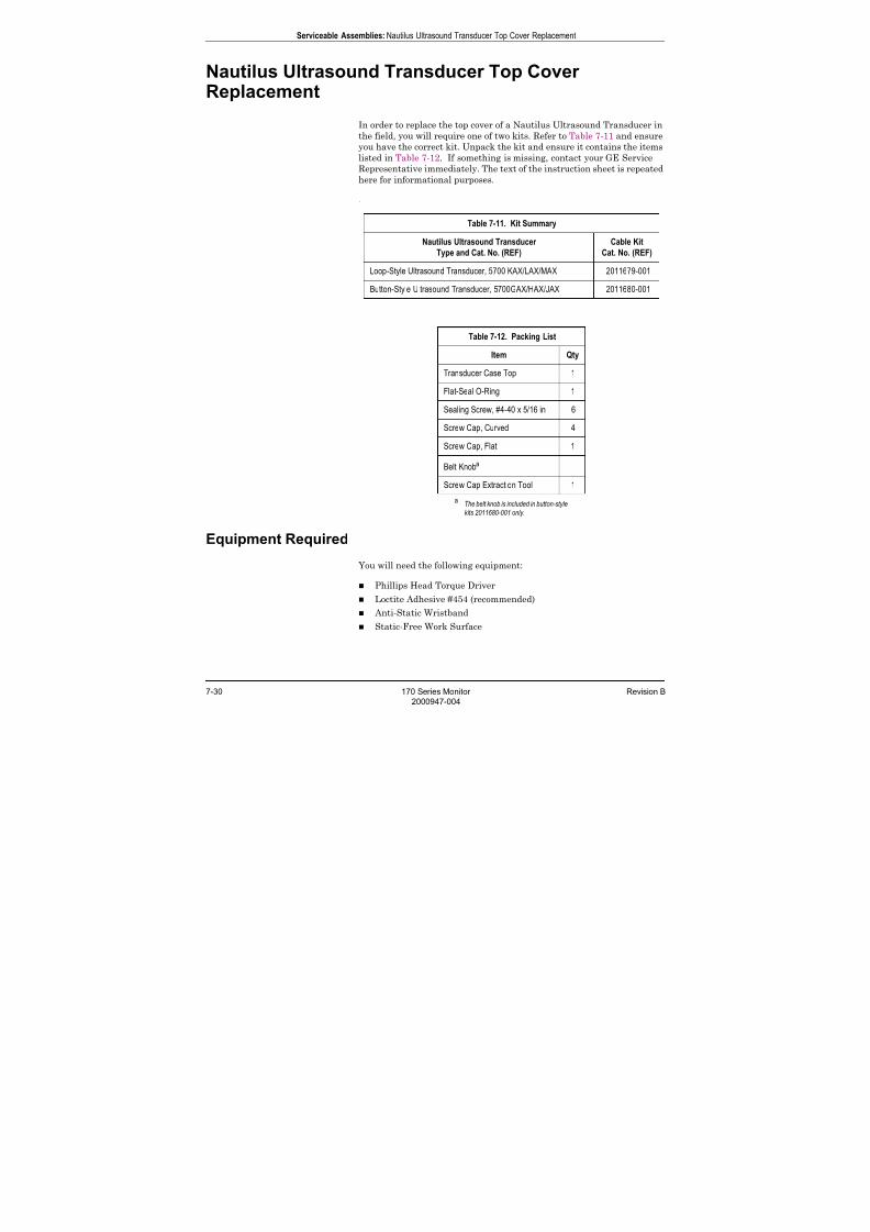
7/25/2019 Serv. Corometrics 170
http://slidepdf.com/reader/full/serv-corometrics-170 160/254
7-30 170 Series Monitor Revision B
2000947-004
Serviceable Assemblies: Nautilus Ultrasound Transducer Top Cover Replacement
Nautilus Ultrasound Transducer Top CoverReplacement
In order to replace the top cover of a Nautilus Ultrasound Transducer in
the field, you will require one of two kits. Refer to Table 7-11 and ensureyou have the correct kit. Unpack the kit and ensure it contains the items
listed in Table 7-12. If something is missing, contact your GE Service
Representative immediately. The text of the instruction sheet is repeated
here for informational purposes.
.
Equipment Required
You will need the following equipment:
Phillips Head Torque Driver
Loctite Adhesive #454 (recommended)
Anti-Static Wristband
Static-Free Work Surface
Table 7-11. Kit Summary
Nautilus Ultrasound Transducer
Type and Cat. No. (REF)
Cable Kit
Cat. No. (REF)
Loop-Style Ultrasound Transducer, 5700 KAX/LAX/MAX 2011679-001
Button-Style Ultrasound Transducer, 5700GAX/HAX/JAX 2011680-001
Table 7-12. Packing List
Item Qty
Transducer Case Top 1
Flat-Seal O-Ring 1
Sealing Screw, #4-40 x 5/16 in 6
Screw Cap, Curved 4
Screw Cap, Flat 1
Belt Knoba
aThe belt knob is included in button-style
kits 2011680-001 only.
Screw Cap Extraction Tool 1
7/25/2019 Serv. Corometrics 170
http://slidepdf.com/reader/full/serv-corometrics-170 161/254
Revision B 170 Series Monitor 7-31
2000947-004
Serviceable Assemblies: Nautilus Ultrasound Transducer Top Cover Replacement
Procedure
1. Turn off the monitor.
2. Unplug the transducer from the monitor.
3. Use the screw cap extraction tool to pry off the five screw caps (Refer
to Figure 7-5). Discard all caps.
CAUTION
HANDLING—Take care not to damage the transducer
base sealing groove.
4. Remove the five sealing screws and discard.
5. Remove the transducer cover and flat-seal o-ring. Discard both items.
6. Follow the instructions for “Nautilus Transducer Reassembly” on
page 7-32.
7/25/2019 Serv. Corometrics 170
http://slidepdf.com/reader/full/serv-corometrics-170 162/254
7-32 170 Series Monitor Revision B
2000947-004
Serviceable Assemblies: Nautilus Transducer Reassembly
Nautilus Transducer Reassembly
CAUTIONS
VISIBLE INSPECTION—Ensure the base sealing
groove, flat-seal o-ring, sealing surface, and sealingscrews are free of visible surface defects, dust, dirt, and
foreign material.
SINGLE-USE COMPONENTS—Do not reuse case top,
flat-seal o-ring, sealing screws, or screw caps. Discard
these items each time a transducer is opened.
SEALS—Wetting of seals is not required.
1. Install new flat-seal o-ring.
2. Install case top and tighten five sealing screws. Hand tighten each
screw a small amount going in a clockwise direction, skipping every
other screw. Repeat until all screws are torqued to 48 in-oz.
3. Apply one drop of Loctite adhesive1 to the perimeter of the hole for
the flat screw cap (Figure 7-5). Insert flat screw cap and press into
place.
4. Apply one drop of Loctite adhesive1 to the perimeter of the hole for a
curved screw cap. Insert the curved screw cap being careful to align it
according to the curvature of the case top; the small burr on the
screw cap side should face the outside edge of the transducer. (See
Figure 7-10 and Figure 7-11.) Press the screw cap firmly into place.
Repeat for the remaining three curved screw caps.
5. For button-style transducers only, install and torque belt knob to
48 in-oz.
6. Refer to “Testing a Repaired Transducer (TOCO or US)” on
page 7-34.
1Using Loctite Adhesive #454 is recommended in order to secure the screw caps.

7/25/2019 Serv. Corometrics 170
http://slidepdf.com/reader/full/serv-corometrics-170 163/254
Revision B 170 Series Monitor 7-33
2000947-004
Serviceable Assemblies: Nautilus Transducer Reassembly
Figure 7-10. Curved Screw Cap Shape, Nautilus Transducer
Figure 7-11. Curved Screw Cap Alignment, Nautilus Transducer

7/25/2019 Serv. Corometrics 170
http://slidepdf.com/reader/full/serv-corometrics-170 164/254
7-34 170 Series Monitor Revision B
2000947-004
Serviceable Assemblies: Testing a Repaired Transducer (TOCO or US)
Testing a Repaired Transducer (TOCO or US)
CAUTIONS
Following completion of the cable replacement procedure:
LEAKAGE TEST—Perform a leakage and dielectric test
on the transducer per applicable standards.
FUNCTIONAL TEST—Perform a functional response
test on the transducer.
7/25/2019 Serv. Corometrics 170
http://slidepdf.com/reader/full/serv-corometrics-170 165/254
Revision B 170 Series Monitor 7-35
2000947-004
Serviceable Assemblies: Replacing the Main Board
Replacing the Main Board
Equipment Required
Phillips screwdriver
Main board
part no. 2000243 (Model 171)
part no. 15269 (Model 172)
part no. 2000324 (Model 173)
part no. 2000973 (Model 174)
Procedure
1. Disconnect the AC adapter from the monitor to completely remove
power.
2. Remove the monitor top cover, disconnecting the display board cableand membrane switch panel cable from J18 and J19, respectively.
3. Disconnect the sensor board cable from J3 on the main board.
4. Disconnect the printhead cable from J1 on the main board.
5. Disconnect the motor cable from J2 on the main board.
6. Disconnect the speaker cable from J4 on the main board.
7. Remove the nine mounting screws from the main board and carefully
place the board on an anti-static surface.
8. For Models 173/174, you will need to transfer the FECG/IUP Boardto the new Main Board. Remove the four mounting screws, then
carefully detach the FECG/IUP Board from J15 and J16 on the Main
Board. Carefully align the FECG/IUP Board onto J15 and J16 on the
new Main Board and push into place. Secure to the stand-offs with
the four screws removed earlier.
9. Position the new board in place and follow steps 1–7 in reverse.

7/25/2019 Serv. Corometrics 170
http://slidepdf.com/reader/full/serv-corometrics-170 166/254
7-36 170 Series Monitor Revision B
2000947-004
Serviceable Assemblies: Replacing the FECG/IUP Board
Replacing the FECG/IUP Board
Follow the instructions for “Replacing the Main Board” on page 7-35 with
the following exceptions:
Retain the existing Main Board Mount a new FECG/IUP Board onto the existing Main Board

7/25/2019 Serv. Corometrics 170
http://slidepdf.com/reader/full/serv-corometrics-170 167/254
Revision B 170 Series Monitor 7-37
2000947-004
Serviceable Assemblies: Replacing the Membrane Switch Panel
Replacing the Membrane Switch Panel
The membrane switch panel cannot be removed from the top cover
without possible damage to the monitor. You must order a new top cover
assembly in order to replace the membrane switch panel.
Equipment Required
Phillips screwdriver
Wrench
Hand file
Top cover
Rear panel adhesive gasket
Rear panel label
Membrane switch panel
Display overlay
Refer to Table 7-13 for order numbers.
Table 7-13. Top Cover Assembly Order Numbers
Item Model 171 Model 172 Model 173 Model 174
Top Cover 2004993-003a 2004993-001b 2004993-002c 2004993-004d
Rear Panel Adhesive Gasket 14561AA
Rear Panel Label 2003930-001
Membrane Switch Panel 15323BA 15323AA
Display Overlay 15324BA 15324AA 15324CA 15324DA
aReplaces older 15453CA top covers.
bReplaces older 15453AA top covers.
cReplaces older 15453BA top covers.
dReplaces older 15453DA top covers.
7/25/2019 Serv. Corometrics 170
http://slidepdf.com/reader/full/serv-corometrics-170 168/254
7-38 170 Series Monitor Revision B
2000947-004
Serviceable Assemblies: Replacing the Membrane Switch Panel
Procedure
1. Disconnect the AC adapter from the monitor to completely remove
power.
2. Follow the instructions for “Removing the Monitor Top Cover” on
page 7-19.3. Unscrew the top cover standoff and set aside. You may need a
wrench to loosen the standoff.
4. Remove the two display board bracket screws. Set aside the display
board and screws.
5. Remove the screw fastening the membrane shield tongue. Set aside
the screw.
6. Remove the rear panel plug in J4 and set aside.
7. Newer monitors have top covers with tabs which fit into
corresponding slots in the bottom enclosure. (Refer to Figure 7-12
and Figure 7-13.) If you are installing a newer tabbed top cover ontoan older bottom enclosure (without slots), you must remove the tabs.
Use a small hand file or other tool to remove the plastic tabs.
8. Apply the new membrane switch panel: peel off the adhesive backing
and position on the new top cover making sure the shield tongue is
threaded through the slot.
IMPORTANT
SHIELD TONGUE—If the shield tongue is caught
between the top cover and the switch panel, the panel
cannot be properly positioned.
9. Screw the shield tongue in place using the old screw.
10. Replace the display board and secure all four screws.
11. Replace the top cover standoff.
12. Install the rear panel gasket on the inside of the cover: remove the
adhesive backing and align over the rear panel connectors.
13. Install the display overlay: remove the adhesive backing and align
on the outside of the top cover.
14. Install the rear panel label on the outside of the cover: remove theadhesive backing and align over the rear panel connectors.
15. Re-connect the display board and membrane switch panel cables to
J18 and J19 on the main board.
16. If you are installing a tabbed cover onto a bottom slotted enclosure,
ensure that the tabs align with the slots.
17. Secure the top cover with the four bottom panel screws.
18. Discard previous top cover assembly.
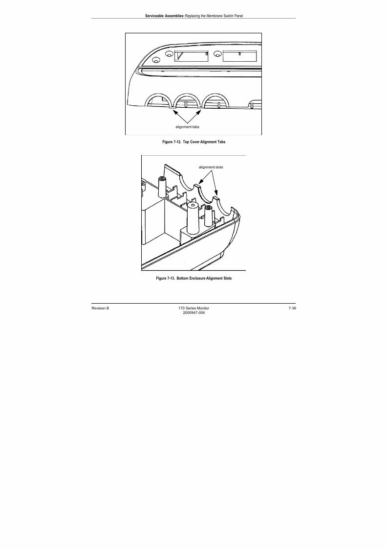
7/25/2019 Serv. Corometrics 170
http://slidepdf.com/reader/full/serv-corometrics-170 169/254
Revision B 170 Series Monitor 7-39
2000947-004
Serviceable Assemblies: Replacing the Membrane Switch Panel
Figure 7-12. Top Cover Alignment Tabs
Figure 7-13. Bottom Enclosure Alignment Slots
alignment tabs
alignment slots
7/25/2019 Serv. Corometrics 170
http://slidepdf.com/reader/full/serv-corometrics-170 170/254
7-40 170 Series Monitor Revision B
2000947-004
Serviceable Assemblies: Replacing a Front Panel Connector
Replacing a Front Panel Connector
Equipment Required
Screwdriver
Connector (see Table 7-14)
De-soldering tool
Soldering iron
Solder
Procedure
1. Disconnect the AC adapter from the monitor to completely remove
power.
2. Follow the instructions for “Removing the Monitor Top Cover” onpage 7-19. It is not necessary to disconnect the cables. You only
need access to the front panel connectors.
3. Follow the instructions for “Replacing the Main Board” on page 7-35.
(There is no need to remove the FECG/IUP Board.)
4. Remove the six screws from the front-end connector shield.
5. De-solder the damaged connector and discard.
6. Solder a new connector in place.
7. Replace the connector shield, main board, and top cover.
Table 7-14. Front Panel Connectors
Connector Color Part Number
US/US2 Blue 212174
UA (TOCO/IUP) White 212173
FECG Dark Grey 212175
COMBI (US/FECG) Blue and Grey 2003692-001

7/25/2019 Serv. Corometrics 170
http://slidepdf.com/reader/full/serv-corometrics-170 171/254
Revision B 170 Series Monitor 7-41
2000947-004
Serviceable Assemblies: Servicing the Recorder
Servicing the Recorder
Replacing the Printhead
Equipment Required Phillips screwdriver
Vernier caliper
Printhead (part no. 2000133-001)
Procedure
1. Remove the AC line cord from the monitor to completely remove
power.
2. Follow the instructions for “Removing the Monitor Top Cover” on
page 7-19.
3. Pry the printhead cable connectors free from the back of theprinthead.
4. Open the recorder drawer.
5. Remove the four screws (two per side) holding the printhead in place.
The printhead will drop out.
6. Insert the new printhead, aligning the edges near the ends flush with
the support plate. Secure with the four screws.
7. Slowly close the drawer observing the roller and printhead. Ensure
that the roller is parallel to the printhead striking the printhead
evenly as the drawer shuts.
8. Replace the printhead cable.
9. Verify that there is a slight gap (0.003 in minimum) between the
shoulder nut standoff and the downstop plate (without paper
installed). Adjust accordingly.
10. Follow the instructions for “Aligning the Printhead” on page 7-43.
11. Once the recorder prints satisfactorily, secure the monitor top cover
in place.
7/25/2019 Serv. Corometrics 170
http://slidepdf.com/reader/full/serv-corometrics-170 172/254
7-42 170 Series Monitor Revision B
2000947-004
Serviceable Assemblies: Servicing the Recorder
Adjusting the Printhead Current
Equipment Required Phillips screwdriver
Digital voltmeter
30 Ω, 20 W, 5% resistor
Procedure
CAUTION
RECORDER STATUS—Ensure the recorder remains off
during this procedure.
1. Remove the AC line cord from the monitor to completely remove
power.
2. Follow the instructions for “Removing the Monitor Top Cover” on
page 7-19, including disconnection of the display board cable and the
membrane switch panel cable from the main board.
3. Disconnect the printhead cable from J1 on the main board.
4. Locate resistor R562 and potentiometer R507 on the main board.
5. Attach the leads of the digital voltmeter across R562.
6. Re-connect the AC adapter cord to the monitor and turn on the
monitor.
7. Measure the voltage across R562 and record the value.
8. Turn off the monitor.
9. Attach a 30 Ω (20 W, 5%) resistor across R562.
10. Turn on the monitor.
11. Adjust potentiometer R507 until the voltage across R562 is 0.5 V less
than the voltage recorded in step 5.
12. Turn off the monitor and remove the voltmeter leads and the 30 Ω
resistor.
7/25/2019 Serv. Corometrics 170
http://slidepdf.com/reader/full/serv-corometrics-170 173/254
Revision B 170 Series Monitor 7-43
2000947-004
Serviceable Assemblies: Servicing the Recorder
Aligning the Printhead
Equipment Required
Phillips screwdriver
Vernier caliper
Printing a Continuous Test Pattern
1. Re-connect the AC adapter cord to the monitor.
2. Access the service setup mode: press and hold the Setup button ;
press and hold the blue Power button; release both buttons.
3. Use the Volume buttons ( or ) to change the number in the UA
display to 100. (On Model 172 Monitors, use the left set of volume
controls.)
4. Press the UA Reference button to activate the FHR display and start
printing the test pattern. See Figure 7-14.
5. Follow the instructions under “Left/Right Alignment” and “Front/
Back Alignment”.
6. Press the Setup button to exit the service setup mode. The
monitor automatically turns to standby.
Front/Back Alignment
1. Follow the instructions for “Adjusting the Printhead Current” on
page 7-42.
2. Print the recorder test pattern. (See “Printing a Continuous Test
Pattern” above.)
3. Load paper and close the recorder drawer.
4. Observe the printing quality under the following conditions:
Press and hold the door toward the rear of the monitor. If the
printing darkens on either side: loosen the four mounting screws;
move the printhead forward slightly on the affected side; then re-
tighten the screws.
Pull and hold the drawer forward slightly. If the printing
darkens on either side: loosen the fours mounting screws; move
the printhead back slightly on the affected side; then re-tighten
the screws.
5. Verify that the print quality is satisfactory when the drawer is
latched in place.
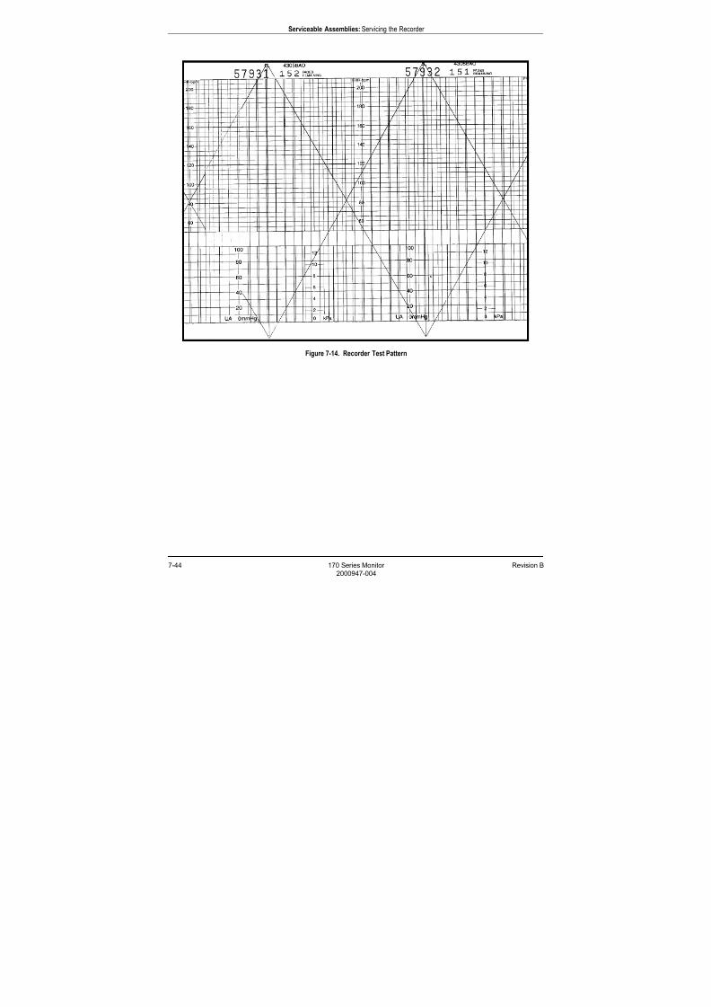
7/25/2019 Serv. Corometrics 170
http://slidepdf.com/reader/full/serv-corometrics-170 174/254
7-44 170 Series Monitor Revision B
2000947-004
Serviceable Assemblies: Servicing the Recorder
Figure 7-14. Recorder Test Pattern
7/25/2019 Serv. Corometrics 170
http://slidepdf.com/reader/full/serv-corometrics-170 175/254
Revision B 170 Series Monitor 7-45
2000947-004
Serviceable Assemblies: Servicing the Recorder
Left/Right Alignment
1. Print the continuous recorder test pattern. (See “Printing a
Continuous Test Pattern” above.)
2. Check the quality of the printed lines. Verify that the horizontal
lines print evenly. Ideally the distance between the right paper
guide at the roller and the first line printed by the test patternshould be 0.490 in which represents a nominal value. Use a vernier
caliper to measure this distance.
3. Use the Volume buttons ( or ) to align the printhead left or
right, respectively. A number between 0 and 255 shows in the FHR
display. The number increases or decreased as you make
adjustments using the Volume buttons.
IMPORTANT
ACCURACY—A common mistake in the field is to adjust
the printhead so that the first test pattern line prints at 0
mmHg on the paper, rather than by measuring the
nominal distance. This method is often inaccurate as it
does not account for paper variations.
For best results:
Use only GE paper.
Ensure paper is correctly loaded as instructed on page 4-2.
Use a vernier caliper to adjust the printhead to its nominal
position.
7/25/2019 Serv. Corometrics 170
http://slidepdf.com/reader/full/serv-corometrics-170 176/254
7-46 170 Series Monitor Revision B
2000947-004
Serviceable Assemblies: Servicing the Recorder
Replacing the Recorder Motor Assembly
Equipment Required Phillips screwdriver
Motor assembly (part no. 15136A)
Procedure
1. Remove the AC line cord from the monitor to completely remove
power.
2. Follow the instructions for “Removing the Monitor Top Cover” on
page 7-19.
3. Follow the instructions for “Replacing the Main Board” on page 7-35.
4. Remove the two screws holding the motor mount in place.
5. Remove the two screws holding the motor assembly on the motor
mount. Retain the motor mount and all screws.
6. Install the new motor on the motor mount and tighten both screws.
7. Position the new motor in place, aligning the motor gear with the
roller gear. Push the motor assembly slightly forward against the
roller gear. There should be a slight clearance between the teeth.
Check clearance by rotating the print roller back and forth. (There
should be a slight rotation.)
8. Secure the motor mount to the main board mounting plate. Tighten
both screws.
9. Replace and align the printhead by following the instructions on
page 7-41 and page 7-43.
10. Replace the main board and secure all eight mounting screws.
11. Re-connect all cables.
12. Replace the monitor top cover.
Cleaning the Printhead
The thermal printhead heater elements must be cleaned at regular
intervals to remove any accumulated paper dust. The heater elements
may be cleaned with methanol or isopropyl alcohol. Care must be taken
to avoid touching the heater elements with bare hands.
CAUTION
AIR DRY—Allow to air dry completely prior to using the
monitor.
7/25/2019 Serv. Corometrics 170
http://slidepdf.com/reader/full/serv-corometrics-170 177/254
Revision B 170 Series Monitor 7-47
2000947-004
Serviceable Assemblies: Servicing the Recorder
Replacing the Sensor Board
Equipment Required Phillips screwdriver
Sensor board (part no. 15231)
Sensor board insulator (part no. 2000147-001)
Cable tie, x2 (part no. 608036)
Cable mount adhesive back, x2 (part no. 608030)
Procedure
1. Remove the AC line cord from the monitor to completely remove
power.
2. Follow the instructions for “Removing the Monitor Top Cover” on
page 7-19.
3. Follow the instructions for “Replacing the Main Board” on page 7-35.
4. Note the location of the printhead assembly relative to the notches on
each side. This is the nominal location for when it is replaced later.
Remove the four screws from the printhead assembly downstop plate
and set aside.
5. Remove the three screws from the main board mounting plate and
slide back and out to remove.
6. Remove the two screws holding the drawer microswitch in place.
7. Snip the sensor board cable tie located on the monitor bottom panel.
8. Pull the recorder drawer forward slightly.
9. Snip the cable tie on the back of the recorder drawer.
10. Pull drawer forward and lift out.
CAUTION
LOOSE ROLLERS—The drawer rollers are normally
held in place by the drawer. Take care not to dislodge
them while the drawer is removed.
11. Turn drawer over and peel off the sensor board insulator.
12. Remove the four flathead screws securing the sensor board. Discard
the board, but retain the screws.
13. Insert the new board, secure all four screws, and cover with a new
insulated sheet.
14. Secure the sensor board cable with a cable tie on the back of the
recorder drawer.
15. Align the drawer over the slot, drop down, and slide into place.
7/25/2019 Serv. Corometrics 170
http://slidepdf.com/reader/full/serv-corometrics-170 178/254
7-48 170 Series Monitor Revision B
2000947-004
Serviceable Assemblies: Servicing the Recorder
16. Pull drawer fully foward to allow slack on the sensor board cable.
17. Secure the sensor board cable with a cable tie on the monitor bottom
panel.
18. Replace the microswitch and secure both screws. Make sure the
microswitch clicks when the drawer is closed.
19. Replace the main board mounting plate, pulling the plate forward,
parallel with the roller while tightening the screws.
20. Return the printhead assembly to its original position as noted in
step 4.
21. Replace the main board, re-connect all cables, and replace the
monitor top cover.
22. Check printing and re-align the printhead as necessary. (See
“Aligning the Printhead” on page 7-43.)
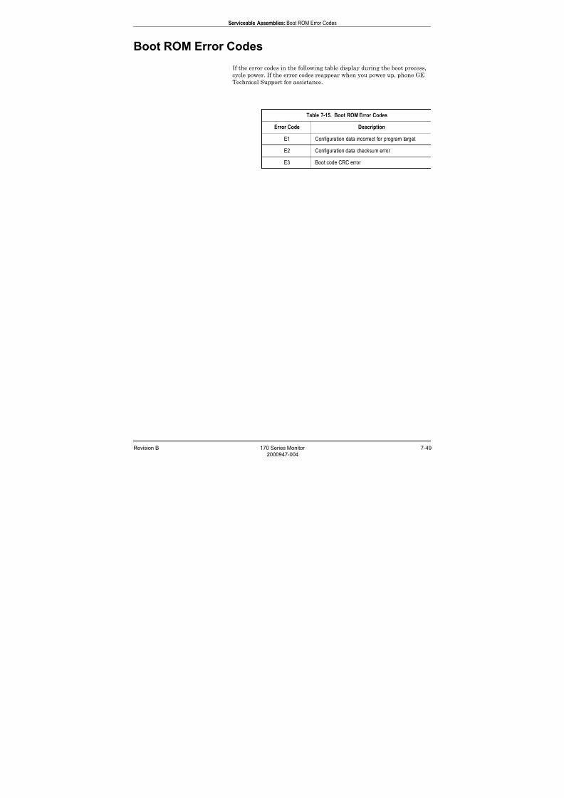
7/25/2019 Serv. Corometrics 170
http://slidepdf.com/reader/full/serv-corometrics-170 179/254
Revision B 170 Series Monitor 7-49
2000947-004
Serviceable Assemblies: Boot ROM Error Codes
Boot ROM Error Codes
If the error codes in the following table display during the boot process,
cycle power. If the error codes reappear when you power up, phone GE
Technical Support for assistance.
Table 7-15. Boot ROM Error Codes
Error Code Description
E1 Configuration data incorrect for program target
E2 Configuration data checksum error
E3 Boot code CRC error

7/25/2019 Serv. Corometrics 170
http://slidepdf.com/reader/full/serv-corometrics-170 180/254
7-50 170 Series Monitor Revision B
2000947-004
Serviceable Assemblies: Boot ROM Error Codes
For your notes
7/25/2019 Serv. Corometrics 170
http://slidepdf.com/reader/full/serv-corometrics-170 181/254
Revision B 170 Series Monitor 8-1
2000947-004
Chapter 8
Peripheral Devices 8The 170 Series Monitor allows connection to optional peripheral
equipment.
This section discusses the following:
Remote Marks Connectors. . . . . . . . . . . . . . . . . . . . . . . . . . . 8-2
Telemetry Connector . . . . . . . . . . . . . . . . . . . . . . . . . . . . . . . 8-3
RS-232 Connectors . . . . . . . . . . . . . . . . . . . . . . . . . . . . . . . . . 8-4
7/25/2019 Serv. Corometrics 170
http://slidepdf.com/reader/full/serv-corometrics-170 182/254
8-2 170 Series Monitor Revision B
2000947-004
Peripheral Devices: Remote Marks Connectors
Remote Marks Connectors
Remote Mark, Fetal Acoustic Stimulator
This receptacle is provided for connection to a Corometrics Model 146Fetal Acoustic Stimulator.
Remote Mark, Remote Event Marker
This receptacle is provided for connection to an optional Corometrics
Remote Event Marker. A Corometrics Remote Event Marker is used to
annotate the strip chart recorder paper with a mark.
The printed mark can be configured as , commonly used to record an
“event”; or it can be configured as , commonly used as an indication
that the mother has perceived fetal movement. The monitor is factory
set with the mark configured as . Refer to “Customizing the Monitor” on page 4-10 for more information on selecting the mark. Refer to the
instructions accompanying the Remote Event Marker for more
information about using the accessory.
7/25/2019 Serv. Corometrics 170
http://slidepdf.com/reader/full/serv-corometrics-170 183/254
Revision B 170 Series Monitor 8-3
2000947-004
Peripheral Devices: Telemetry Connector
Telemetry Connector
This connector is for future interfacing to the receiver of a Corometrics
Model 340 Telemetry System.
NOTE
The monitor, receiver, and transmitter must all be turned on.
NOTE When any telemetry mode is detected (US or TOCO), all
equivalent front panel modes (US, US2, or TOCO) are ignored.
You cannot “mix and match” telemetry and monitor modes.
The telemetry connected annotation is printed on the bottom line of
the top grid of the strip chart paper:
upon commencement of telemetry monitoring; and
every 30 minutes along with the modes.
The telemetry disconnected annotation is printed on the strip chart
paper if:
you unplug the telemetry receiver from the 170 Series Monitor;
you turn off the receiver;
you turn off the transmitter; or
the receiver does not detect any active mode information from the
transmitter.

7/25/2019 Serv. Corometrics 170
http://slidepdf.com/reader/full/serv-corometrics-170 184/254
8-4 170 Series Monitor Revision B
2000947-004
Peripheral Devices: RS-232 Connectors
RS-232 Connectors
Two RS-232C serial interface receptacles (RJ-45) allow connecting the
170 Series Monitor to the following devices:
Critikon Model 1846/1846SX Blood Pressure Monitor Quantitative Sentinel/Perinatal System
Nellcor N-400 Fetal Pulse Oximeter
115-Compatible Device
Table 8-1 lists the factory default settings for each port. Refer to
Customizing the Monitor on page 4-10 for information on using the
service setup mode to change these settings.
Baud Rate
Select a baud rate that is compatible with the external device. The
available settings: 600, 1200, 2400, 4800, 9600, 19,200, and 384,000 bps.
Mode
Select a communications mode compatible with the external device.
HP or HP with NotesSelect HP or HP w/notes for connecting to a Marquette Quantitative/
Perinatal System or another central system that uses the Hewlett
Packard communications protocol. HP mode does not print central
station annotations on the fetal monitor strip chart, whereas HP w/notes
does.
Ext. BPSelect ext. BP for connecting to a Critikon Model 1846/1846SX Blood
Pressure Monitor.
Table 8-1. Communication Default SettingsRS-232 Port Intended Device Mode Baud Rate
1 QS System HP 1200
2 Critikon Model 1846/1846SX ext. BP 600

7/25/2019 Serv. Corometrics 170
http://slidepdf.com/reader/full/serv-corometrics-170 185/254
Revision B 170 Series Monitor 8-5
2000947-004
Peripheral Devices: RS-232 Connectors
Ext. FSpO2
Select ext. FSpO2 for connecting to a Nellcor Fetal Pulse Oximeter.
FactoryThe FACTORY mode is reserved for factory testing only.
115 UpdateSelect for backward-compatibility so the 170 Series Monitor can
operate in a Model 115-compatible communication mode. This mode
outputs all available information and ignores requests from a host
computer system.
115 Transmit/ReceiveSelect for backward-compatibility so the 170 Series Monitor can
operate in a Model 115-compatible communication mode. This mode
only outputs data requested from a host computer system.
7/25/2019 Serv. Corometrics 170
http://slidepdf.com/reader/full/serv-corometrics-170 186/254
8-6 170 Series Monitor Revision B
2000947-004
Peripheral Devices: RS-232 Connectors
Critikon Model 1846/1846SX
Critikon Model 1846/1846SX Monitors can be interfaced to a 170 Series
Monitor to provide a printout of NBP values on the strip chart paper.
1. Refer to Table 8-2 for the appropriate interface cable. Connect one
end to an available RS-232C port (1 or 2) on the 170 Series Monitor;connect the other end to the serial communications port on the blood
pressure monitor. Refer to the Critikon documentation for
information on the name of the connector.
2. Access the fetal monitor service setup mode and set the baud rate
and mode for the appropriate port to 600 and ext. BP, respectively;
then exit the service setup mode.
3. Be aware of the following information specific to Critikon monitors:
The clock on the Critikon Modes 1846/1846SX Monitors must be
set to within 10 minutes of the 170 Series Monitor. If the clocks
are not within 10 minutes of each other, the time will print with
each blood pressure reading. Due to the storage capabilities of Critikon monitors, it is
recommended that power be cycled at the beginning of each data
session. This ensures that any previously stored data is cleared.
When using STAT mode on a Critikon monitor, the 170 Series
Monitor does not print the time with each reading due to
overcrowding on the strip chart. Instead the time is printed once
every three to five minutes.
The Critikon Model 1846SX discards NBP values after 90
minutes.

7/25/2019 Serv. Corometrics 170
http://slidepdf.com/reader/full/serv-corometrics-170 187/254
Revision B 170 Series Monitor 8-7
2000947-004
Peripheral Devices: RS-232 Connectors
Quantitative Sentinel/Perinatal System
Through this interface, the 170 Series Monitor outputs FHR and UA data
to a central information such as GE’s Quantitative Sentinel/Perinatal
System. Annotations made at the central station can be optionally
printed on the strip chart paper of the 170 Series Monitor as summarized
below:
Each message is preceded by a computer icon ( ).
Messages are restricted to a maximum length of
50 characters.
Lower-case letters are converted to upper-case letters.
Non-standard characters are replaced with spaces.
The 170 Series Monitor can be configured with the remote annotation
capability enabled (HP w/notes mode) or disabled (HP mode). The
following is an example of a remote message sent to a 170 Series Monitor
from a central information system using this serial communications
protocol:
<SPW> AVERAGE VARIABILITY
where SPW is an example of a physician’s initials.
To connect a central information system:
1. Refer to Table 8-2 for the appropriate interface cable. Connect one
end to an available RS-232C connector (1 or 2) on the 170 Series
Monitor; connect the other end to the wallplate wired to the central
information system. For a Marquette Quantitative Sentinel/Perinatal
System: the interface cable is catalog number (REF) 1376AAO; thecorresponding wallplate connector is labeled RS-232
COMMUNICATIONS.
2. Access the monitor’s service setup mode and set the baud rate and
mode to either HP or HP w/notes mode, respectively; then exit the
service setup mode.

7/25/2019 Serv. Corometrics 170
http://slidepdf.com/reader/full/serv-corometrics-170 188/254
8-8 170 Series Monitor Revision B
2000947-004
Peripheral Devices: RS-232 Connectors
Nellcor Puritan Bennett Model N-400
Fetal Pulse Oximeter
Through this interface, FSpO2 readings provided by an NPB Model N-
400 are printed every five minutes on the strip chart paper of the 170
Series Monitor. The reading is printed in the annotation area betweenthe top and bottom grids. A solid diamond marker, above the data,
marks the time of the reading and identifies the data source as an
external device. The following is an example annotation:
FSpO2 47%
In addition, the FSpO2 data is trended on the bottom grid of the strip
chart paper as a beaded trace. The trend uses a 0-100% scale. Refer to
Figure 8-1.
Figure 8-1. FSpO2 Data Example
To connect the Model N-400:
1. Using interface cable catalog number (REF) 1557AAO/BAO: connect
one end to an available RS-232C port on the 170 Series Monitor;
connect the other end to the Serial Communications port on the pulse
oximeter.
NOTE This cable can be used with both 120/2121is and 170 Series
Monitors. Although the 120/2120is uses 6-pin RJ-11 connectors
and the 170 uses 8-pin RJ-45 connectors, the latter is center
keyed to account for this. The 170 uses RJ-45 connectors toprovide for future interface features.
2. Access the monitor’s service setup mode and set the baud rate to
2400 and the mode to ext. FSpO2; then exit the service setup mode.
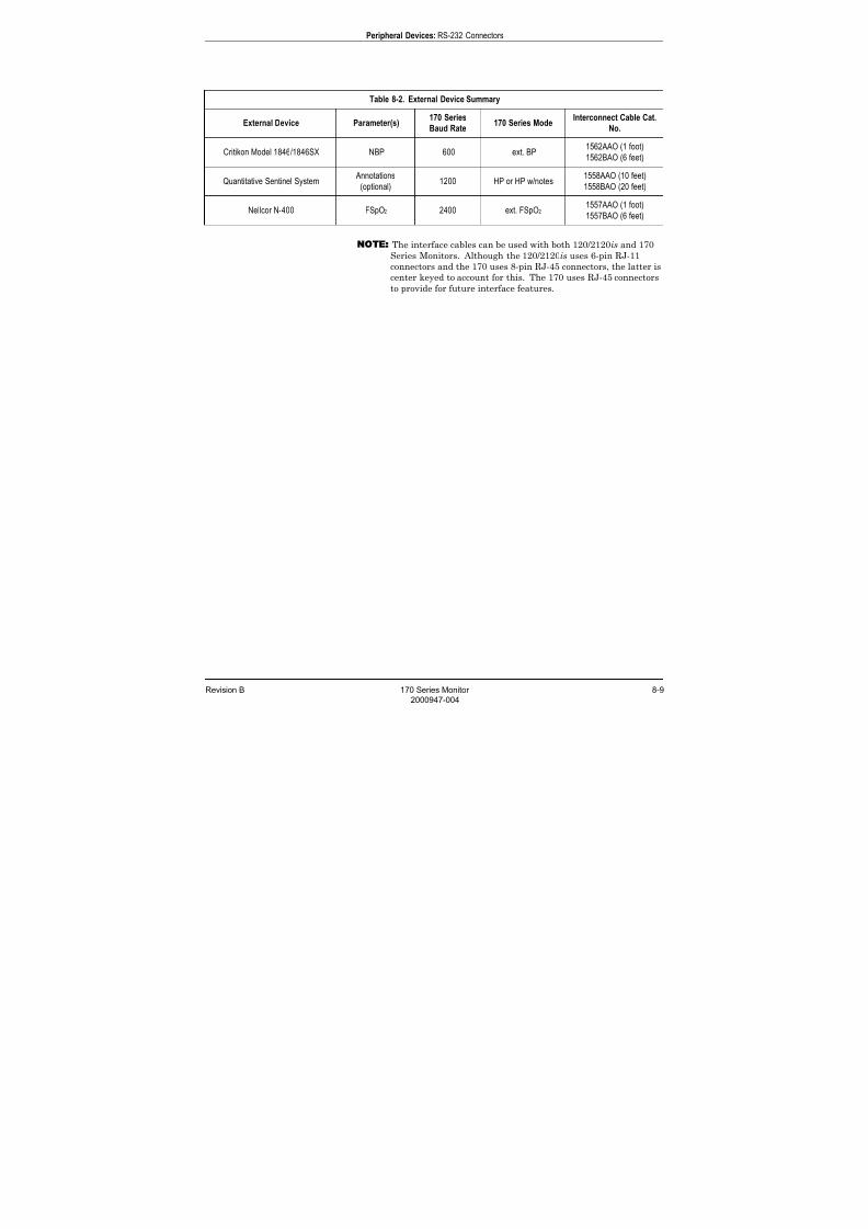
7/25/2019 Serv. Corometrics 170
http://slidepdf.com/reader/full/serv-corometrics-170 189/254
Revision B 170 Series Monitor 8-9
2000947-004
Peripheral Devices: RS-232 Connectors
NOTE The interface cables can be used with both 120/2120is and 170
Series Monitors. Although the 120/2120is uses 6-pin RJ-11
connectors and the 170 uses 8-pin RJ-45 connectors, the latter is
center keyed to account for this. The 170 uses RJ-45 connectorsto provide for future interface features.
Table 8-2. External Device Summary
External Device Parameter(s)170 Series
Baud Rate170 Series Mode
Interconnect Cable Cat.
No.
Critikon Model 1846/1846SX NBP 600 ext. BP1562AAO (1 foot)
1562BAO (6 feet)
Quantitative Sentinel System Annotations
(optional)1200 HP or HP w/notes
1558AAO (10 feet)
1558BAO (20 feet)
Nellcor N-400 FSpO2 2400 ext. FSpO21557AAO (1 foot)
1557BAO (6 feet)
7/25/2019 Serv. Corometrics 170
http://slidepdf.com/reader/full/serv-corometrics-170 190/254
8-10 170 Series Monitor Revision B
2000947-004
Peripheral Devices: RS-232 Connectors
Model 115-Compatible Communications Protocols
Two options provide backward-compatibility so that the 170 Series
Monitor can operate in a Model 115-compatible communication mode:
115 Update Mode: The 115 Update mode outputs all available
information and ignores requests from a host computer system. 115 Transmit/Receive: The 115 Transmit/Receive mode only outputs
data requested from a host computer system.
When the Model 115 Fetal Monitor was released, many customers
developed their own interfaces for communicating with the monitor.
Setting the 170 Series Monitor to one of these communication modes
allows these users to use their existing interfaces with the 170 Series
Monitor as well.
The 170 Series Monitor emulates the Corometrics Model 830 Converter’s
implementation of the 115 Communication Protocols. This protocol is
named after the Corometrics Model 115 Fetal Monitor in which it
originated.
NOTE The baud rate must match the external computer; however, the
recommended baud rate is 9600. Lower baud rates may result in
some data loss.
7/25/2019 Serv. Corometrics 170
http://slidepdf.com/reader/full/serv-corometrics-170 191/254
Revision B 170 Series Monitor 8-11
2000947-004
Peripheral Devices: RS-232 Connectors
115 Update Mode All information is transmitted from the 170 Series Monitor as soon as the
information becomes available.
IMPORTANT
DATA REQUESTS—When set to the 115 Update Mode,the 170 Series Monitor will not respond to any requests
for information sent from an external (host) computer.
Heart rate data is transmitted on a quarter second basis. Uterine
activity is transmitted eight times per second. Modes are transmitted
once per minute, and whenever a mode change occurs. Annotation
messages are sent as they are entered from the Annotations window.
Event marks are transmitted each time the Mark button is selected.
Fetal movement data is transmitted four times per second. Recorder
status (PAPER OUT) information is transmitted once per second, when
active, until the condition is resolved.
NOTE
Refer to Requested Data Format on page 8-12 for information
about the response data format. The format is the same for both
the 115 Update mode and the 115 Transmit/Receive mode.
7/25/2019 Serv. Corometrics 170
http://slidepdf.com/reader/full/serv-corometrics-170 192/254

7/25/2019 Serv. Corometrics 170
http://slidepdf.com/reader/full/serv-corometrics-170 193/254
Revision B 170 Series Monitor 8-13
2000947-004
Peripheral Devices: RS-232 Connectors
Transmitted Data FormatThe format of the information transmitted from the 170 Series Monitor to
the external computer is shown in Figure 8-3.
NOTE
This applies to both 115 Update mode and 115 Transmit/Receive
mode.
The definitions of the bytes are as follows:
Monitor TypeThis field contains a 1-byte ASCII value indicating the type of monitor
sending the information. The 170 Series Monitor is set to a fixed value of
9 (39H).
Response TypeThis 1-byte value indicates the type of information being sent from the
170 Series Monitor as shown in Table 8-3.
Monitor IDThis 1-byte ASCII value indicates the ID number of the monitor
information. The 170 Series Monitor sets this byte to a fixed value of 0
(30H).
Data FieldThis field of n-bytes contains the actual data sent from the monitor to
the external computer. The contents of this field for each response is
given below:
Event Mark: This data field is empty whenever the monitor’s Mark
button is selected.
Heart Rate: This data field contains two or three ASCII characters
representing the value of the heart rate. A value of 00 (30H, 30H)
indicates a penlift condition. Heart rate data (including penlift data)
is transmitted four times per second.
Uterine Activity: This data field contains two or three ASCII
characters representing the value of uterine activity. A value of 128
(31H, 32H, 38H) indicates a penlift condition. Uterine activity data
(including penlift data) is transmitted eight times per second.
Modes: This data field contains two ASCII characters indicating the
mode. The first character is the combined mode of both heart rates
according to Table 8-4. The second character is the mode for uterine
activity as listed in Table 8-5. Mode data is transmitted at startup,
with each mode change, with each request, and once every minute.

7/25/2019 Serv. Corometrics 170
http://slidepdf.com/reader/full/serv-corometrics-170 194/254
8-14 170 Series Monitor Revision B
2000947-004
Peripheral Devices: RS-232 Connectors
Fetal Movement: This field contains one ASCII character
representing the current status of the FM signal: low or high. If the
data byte is a 0 (30H), then the signal is low indicating no movement
is detected; if the data byte is 1 (31H), then the signal is high
indicating fetal movement is detected. If the fetal movement feature
is not in the monitor, the data byte is 2 (32H). If the fetal movement
feature is present but not enabled, the data byte is 4 (34H). This
data is transmitted four times per second. (Fetal movement
detection circuitry is an option which can be purchased for the 170
Series Monitor.
Recorder Status: This field contains one ASCII character
representing the current status of the PAPER OUT* signal: low or
high. If the data byte is a 0 (30H), then the signal is low indicating
paper is loaded and the recorder door is closed; if the data byte is 1
(31H), then the signal is high indicating a paper out condition. This
data is transmitted once per second, when active.
End of TextThis 1-byte field contains the value 03H. If this byte is sent immediately
following the Monitor ID, then the 170 Series Monitor will cancel
transmission of all data.
LimitationsThe only restriction on the information transmitted during either 115
communication mode occurs when the baud rate is set below 4800 baud.
Under this condition, data loss may occur.
NOTE The recommended baud rate is 9600.
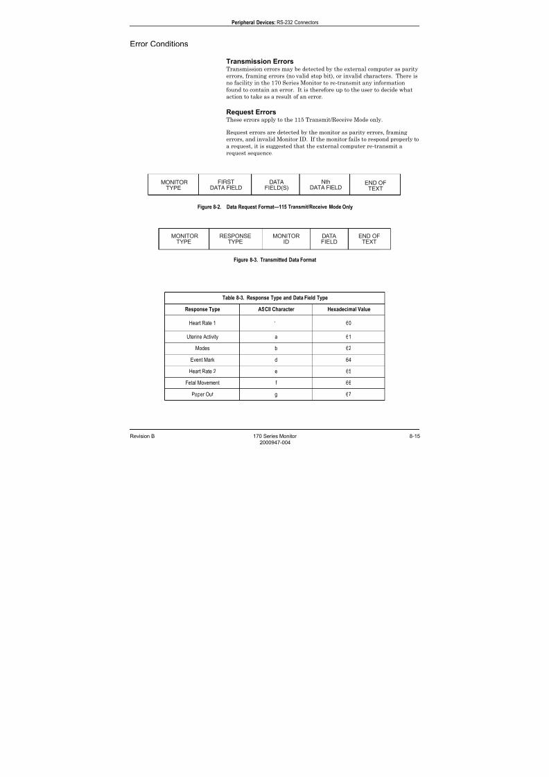
7/25/2019 Serv. Corometrics 170
http://slidepdf.com/reader/full/serv-corometrics-170 195/254
Revision B 170 Series Monitor 8-15
2000947-004
Peripheral Devices: RS-232 Connectors
Error Conditions
Transmission ErrorsTransmission errors may be detected by the external computer as parity
errors, framing errors (no valid stop bit), or invalid characters. There is
no facility in the 170 Series Monitor to re-transmit any information
found to contain an error. It is therefore up to the user to decide whataction to take as a result of an error.
Request ErrorsThese errors apply to the 115 Transmit/Receive Mode only.
Request errors are detected by the monitor as parity errors, framing
errors, and invalid Monitor ID. If the monitor fails to respond properly to
a request, it is suggested that the external computer re-transmit a
request sequence.
Figure 8-2. Data Request Format—115 Transmit/Receive Mode Only
Figure 8-3. Transmitted Data Format
MONITORTYPE
FIRSTDATA FIELD
END OFTEXT
DATAFIELD(S)
NthDATA FIELD
Table 8-3. Response Type and Data Field Type
Response Type ASCII Character Hexadecimal Value
Heart Rate 1 60
Uterine Activity a 61
Modes b 62
Event Mark d 64
Heart Rate 2 e 65
Fetal Movement f 66
Paper Out g 67
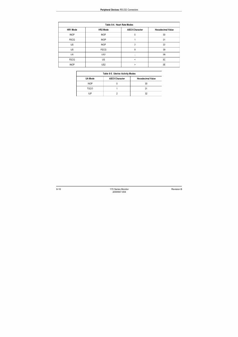
7/25/2019 Serv. Corometrics 170
http://slidepdf.com/reader/full/serv-corometrics-170 196/254
8-16 170 Series Monitor Revision B
2000947-004
Peripheral Devices: RS-232 Connectors
Table 8-4. Heart Rate Modes
HR1 Mode HR2 Mode ASCII Character Hexadecimal Value
INOP INOP 0 30
FECG INOP 1 31
US INOP 2 32
US FECG 9 39
US US2 ; 3B
FECG US < 3C
INOP US2 > 3E
Table 8-5. Uterine Activity Modes
UA Mode ASCII Character Hexadecimal Value
INOP 0 30
TOCO 1 31
IUP 2 32
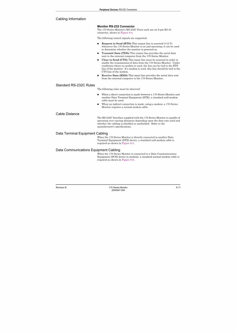
7/25/2019 Serv. Corometrics 170
http://slidepdf.com/reader/full/serv-corometrics-170 197/254
Revision B 170 Series Monitor 8-17
2000947-004
Peripheral Devices: RS-232 Connectors
Cabling Information
Monitor RS-232 Connector The 170 Series Monitor’s RS-232C Ports each use an 8-pin RJ-45
connector, shown in Figure 8-4.
The following control signals are supported:
Request to Send (RTS): This output line is asserted (+12 V)
whenever the 170 Series Monitor is on and operating; it can be used
to determine whether the monitor is powered on.
Transmit Data (TXD): This output line provides the serial data
sent to the external computer from the 170 Series Monitor.
Clear to Send (CTS): This input line must be asserted in order to
enable the transmission of data from the 170 Series Monitor. Under
conditions where no modem is used, the line can be tied to the RTS
line of the monitor. If a modem is used, this line should be tied to the
CTS line of the modem.
Receive Data (RXD): This input line provides the serial data sentfrom the external computer to the 170 Series Monitor.
Standard RS-232C RulesThe following rules must be observed:
When a direct connection is made between a 170 Series Monitor and
another Data Terminal Equipment (DTE), a standard null-modem
cable must be used.
When an indirect connection is made, using a modem, a 170 Series
Monitor requires a normal-modem cable.
Cable DistanceThe RS-232C Interface supplied with the 170 Series Monitor is capable of
operating over varying distances depending upon the data rate used and
whether the cabling is shielded or unshielded. Refer to the
manufacturer’s specifications.
Data Terminal Equipment CablingWhen the 170 Series Monitor is directly connected to another Data
Terminal Equipment (DTE) device, a standard null-modem cable is
required as shown in Figure 8-5.
Data Communications Equipment CablingWhen the 170 Series Monitor is connected to a Data Communications
Equipment (DCE) device (a modem), a standard normal-modem cable is
required as shown in Figure 8-6.

7/25/2019 Serv. Corometrics 170
http://slidepdf.com/reader/full/serv-corometrics-170 198/254
8-18 170 Series Monitor Revision B
2000947-004
Peripheral Devices: RS-232 Connectors
Figure 8-4. RJ-45 Connector (facing the rear panel from the outside)
Table 8-6. RS-232 Connector 1
Pin Number Signal Name Signal Description
1 +5V 200 mA Fused
2 RTS Request to Send Output from Monitor
3 RXD Receive Data Input to Monitor
4 GND Signal Ground
5 GND Signal Ground
6 TXD Transmit Data Output from Monitor
7 CTS Clear to Send Input to Monitor
8 +5V 200 mA Fused
Table 8-7. RS-232 Connector 2
Pin Number Signal Name Signal Description
1 GND Signal Ground
2 RTS Request to Send Output from Monitor
3 RXD Receive Data Input to Monitor
4 GND Signal Ground
5 GND Signal Ground
6 TXD Transmit Data Output from Monitor
7 CTS Clear to Send Input to Monitor
8 GND Signal Ground
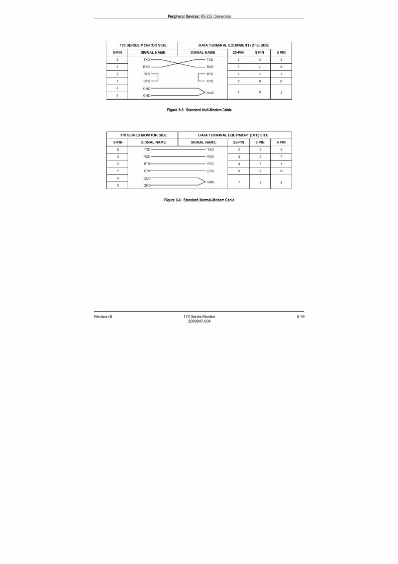
7/25/2019 Serv. Corometrics 170
http://slidepdf.com/reader/full/serv-corometrics-170 199/254
Revision B 170 Series Monitor 8-19
2000947-004
Peripheral Devices: RS-232 Connectors
Figure 8-5. Standard Null-Modem Cable
Figure 8-6. Standard Normal-Modem Cable

7/25/2019 Serv. Corometrics 170
http://slidepdf.com/reader/full/serv-corometrics-170 200/254
8-20 170 Series Monitor Revision B
2000947-004
For your notes

7/25/2019 Serv. Corometrics 170
http://slidepdf.com/reader/full/serv-corometrics-170 201/254
Revision B 170 Series Monitor 9-1
2000947-004
Chapter 9
Maintenance 9 All equipment, no matter how reliable, needs to be maintained on a
regular basis. This chapter describes general care and cleaning
instructions for the 170 Series Monitor and its accessories. If an
accessory is not listed, consult the manufacturer’s instructions.
This chapter describes the following:
Cleaning . . . . . . . . . . . . . . . . . . . . . . . . . . . . . . . . . . . . . . . . . 9-2
Preventative Maintenance Inspection . . . . . . . . . . . . . . . . . 9-5

7/25/2019 Serv. Corometrics 170
http://slidepdf.com/reader/full/serv-corometrics-170 202/254
9-2 170 Series Monitor Revision B
2000947-004
Maintenance: Cleaning
Cleaning
CAUTION
PREPARATION—Unplug the monitor from the AC
power source and detach all accessories from themonitor. Do not immerse accessories in any liquid. Do
not use abrasive cloth or cleaners on monitor or
accessories.
Cleaning the Monitor Exterior
To clean the exterior of the monitor, including the displays and the
membrane switch panel:
1. Wipe any fluids from the surface of the monitor.
2. Dampen a cloth or paper towel with isopropyl alcohol and gentlyrub soiled area until clean.
7/25/2019 Serv. Corometrics 170
http://slidepdf.com/reader/full/serv-corometrics-170 203/254
Revision B 170 Series Monitor 9-3
2000947-004
Maintenance: Cleaning
Cleaning the Tocotransducer, Ultrasound Transducer, and
Legplate
CAUTIONS
ABRASION—Do not use abrasive cloth, sharp objects, orabrasive cleaners.
ALCOHOL—Do not use Alcohol in cleaning solutions.
DISCONNECTION—Detach the transducers/cables/
legplate from the monitor.
IMMERSION—Do not immerse transducers/cables/
legplate or hold under running water.
1. Dampen a cloth or paper towel with one of the following products;
then wring out until only slightly wet:
Sodium Hypochlorite 5.25 % (Bleach) diluted 10:1
Cidex
Sporicidin
Soap and water
2. Rub soiled area until clean, taking care not to excessively wet the
tocotransducer diaphragm seal or the contact surface of the
ultrasound transducer.
3. Use a cloth dampened with water on the contact surface of the
ultrasound transducer and around the seal of the tocotransducer. Do
not use a sharp object which might damage the seal of thetocotransducer.
4. Dry all accessories with a soft, dry cloth.
7/25/2019 Serv. Corometrics 170
http://slidepdf.com/reader/full/serv-corometrics-170 204/254
9-4 170 Series Monitor Revision B
2000947-004
Maintenance: Cleaning
Cleaning the UA Strain Gauge
1. Remove the plastic dome.
2. If desired, wash the transducer with sterile water or saline solution.
3. Carefully clean the diaphragm seal with a cotton swab to remove
deposits. Avoid excessive pressure since this may damage thediaphragm. If there are excessive stains on the diaphragm or sides of
the transducer, remove with a cotton swab and solvents of increasing
strength. Do not use pumice, Ajax, Bon Ami or other abrasives.
4. After cleaning, rinse the transducer thoroughly in distilled water and
replace the dome loosely.
5. Dry the transducer with sterile gauze.
CAUTIONS
AUTOCLAVE—Do not autoclave pressure transducer.
IMMERSION—Do not immerse any part of the electrical
connector of the transducer in the cleaning solution at any
time. Examine the outer sheath of the cable for
perforations. If the outer covering is damaged in any way,
do not immerse the cable in the cleaning solution; this may
result in moisture entering the transducer case, which is
vented through the cable.
WARNING
LIQUIDS—If liquids enter the electrical connector, check
the resistance between the electrical element and thetransducer case. A resistance level of greater than 10 M¾
ensures that the leakage current is within acceptable
levels for safe use on patients.
6. Leave transparent dome attached to the transducer during storage,
but slacken the locking ring at least one quarter of a turn.
CAUTION
STERILIZATION—Prior to patient use, ensure the dome
is sterile.
7/25/2019 Serv. Corometrics 170
http://slidepdf.com/reader/full/serv-corometrics-170 205/254
Revision B 170 Series Monitor 9-5
2000947-004
Maintenance: Preventative Maintenance Inspection
Preventative Maintenance Inspection
Equipment Required
Digital Multimeter
Dielectric Tester
Leakage Current Tester
Aluminum Foil
Ultrasound Test Body
(ultrasound transducer wrapped in aluminum foil)
Tocotransducer Test Body
(tocotransducer wrapped in aluminum foil)
FECG Test Body for Model 173 or 174 only
(Shorted legplate with all three leads tied together)
IUP Test Body for Model 173 or 174 only
(SensorTip transducer wrapped in aluminum foil)
Anti-Static Wristband
Static-Fee Work Surface
170 Series Operator’s Manual
Visual Inspection
Inspect the following for excess wear and/or signs of damage:
Power Supply Cord
AC-to-DC Converter
AC Line Cord
Ultrasound Transducer(s)
Legplate(s)
IUPC Transducer(s)
Remote Event Marker
Monitor Input Receptacles
Chassis
Membrane Switch Panel
Internal Harnesses/Connectors
Display Panel
7/25/2019 Serv. Corometrics 170
http://slidepdf.com/reader/full/serv-corometrics-170 206/254
9-6 170 Series Monitor Revision B
2000947-004
Maintenance: Preventative Maintenance Inspection
Cleaning
Clean the monitor’s exterior. Refer to “Cleaning the Monitor
Exterior” on page 9-2.
Clean the recorder printhead. Refer to “Cleaning the Printhead”
on page 7-46.
Clean the monitor’s accessories. Refer to “Cleaning the
Tocotransducer, Ultrasound Transducer, and Legplate” on page 9-
3.
Clean the monitor’s interior using a hand-held vacuum.
Calibration
Adjust the printhead. Refer to “Aligning the Printhead” on page 7-
43.
Calibrate the tocotransducer(s). Refer to “Tocotransducer
Calibration” on page 7-20.
7/25/2019 Serv. Corometrics 170
http://slidepdf.com/reader/full/serv-corometrics-170 207/254
Revision B 170 Series Monitor 9-7
2000947-004
Maintenance: Preventative Maintenance Inspection
Electrical Safety Tests
Electrical safety tests provide a method of determining if potential
electrical hazards to the patient or operator of the device exist.
Recommendations GE recommends that you perform all safety tests presented in this
chapter:
upon receipt of the device (monitor and its associated equipment)
every twelve months thereafter
each time the main enclosure is disassembled or a circuit board is
removed, tested, repaired, or replaced, and
record the date and results in a Maintenance Repair Log.
These instructions are intended for every component in the system.
WARNING
MAINTENANCE SCHEDULE—Failure to implement a
satisfactory maintenance schedule may cause undue
equipment failure and possible health hazards. Unless you
have an Equipment Maintenance Contract, GE does not in
any manner assume the responsibility for performing the
recommended maintenance procedures. The sole
responsibility rests with the individual or institution using
the equipment. GE service personnel may, at their
discretion, follow the procedures provided in this manual
as a guide during visits to the equipment site.
Test ConditionsElectrical safety tests may be performed under normal ambient conditions
of temperature, humidity, and pressure.

7/25/2019 Serv. Corometrics 170
http://slidepdf.com/reader/full/serv-corometrics-170 208/254
9-8 170 Series Monitor Revision B
2000947-004
Maintenance: Preventative Maintenance Inspection
Unit to Primary Leakage
1. Configure a leakage tester to perform a unit AC line leakage test.
2. Turn ON the monitor using the monitor’s On/Standby button.
3. Verify the following:
<300 µ A
(132–253 VAC, or at the line voltage at your facility +10%)
4. Record the primary leakage for the following conditions:
Table 9-1. Unit to Primary Leakage Conditions
Neutral Ground Power (Polarity)
__________ Closed __________ Closed __________ Normal
__________ Closed __________ Open __________ Normal
__________ Closed __________ Open __________ Reversed
__________ Closed __________ Closed __________ Reversed
__________ Open __________ Closed __________ Normal
__________ Open __________ Closed __________ Reversed
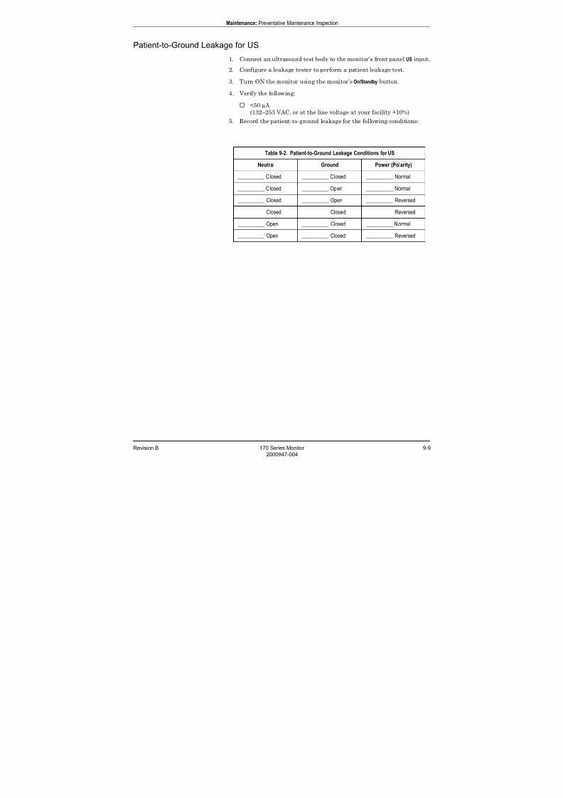
7/25/2019 Serv. Corometrics 170
http://slidepdf.com/reader/full/serv-corometrics-170 209/254
Revision B 170 Series Monitor 9-9
2000947-004
Maintenance: Preventative Maintenance Inspection
Patient-to-Ground Leakage for US
1. Connect an ultrasound test body to the monitor’s front panel US input.
2. Configure a leakage tester to perform a patient leakage test.
3. Turn ON the monitor using the monitor’s On/Standby button.
4. Verify the following:
<50 µ A
(132–253 VAC, or at the line voltage at your facility +10%)
5. Record the patient-to-ground leakage for the following conditions:
Table 9-2. Patient-to-Ground Leakage Conditions for US
Neutral Ground Power (Polarity)
__________ Closed __________ Closed __________ Normal
__________ Closed __________ Open __________ Normal
__________ Closed __________ Open __________ Reversed
__________ Closed __________ Closed __________ Reversed
__________ Open __________ Closed __________ Normal
__________ Open __________ Closed __________ Reversed

7/25/2019 Serv. Corometrics 170
http://slidepdf.com/reader/full/serv-corometrics-170 210/254
9-10 170 Series Monitor Revision B
2000947-004
Maintenance: Preventative Maintenance Inspection
Patient-to-Line Leakage for US
1. Connect an ultrasound test body to the monitor’s front panel US input.
2. Configure a leakage tester to perform a line leakage test.
3. Turn ON the monitor using the monitor’s On/Standby button.
4. Verify the following:
<50 µ A
(132–253 VAC, or at the line voltage at your facility +10%)
5. Record the patient-to-line leakage for the following conditions:
Table 9-3. Patient-to-Line Leakage Conditions for US
Neutral Ground Power (Polarity)
__________ Closed __________ Closed __________ Normal
__________ Closed __________ Closed __________ Reversed
__________ Open __________ Closed __________ Normal
__________ Open __________ Closed __________ Reversed

7/25/2019 Serv. Corometrics 170
http://slidepdf.com/reader/full/serv-corometrics-170 211/254
Revision B 170 Series Monitor 9-11
2000947-004
Maintenance: Preventative Maintenance Inspection
Patient-to-Ground Leakage for US2
1. Connect an ultrasound test body to the monitor’s front panel US2
input.
2. Configure a leakage tester to perform a patient leakage test.
3. Turn ON the monitor using the monitor’s On/Standby button.
4. Verify the following:
<50 µ A
(132–253 VAC, or at the line voltage at your facility +10%)
5. Record the patient-to-ground leakage for the following conditions:
Table 9-4. Patient-to-Ground Leakage Conditions for US2
Neutral Ground Power (Polarity)
__________ Closed __________ Closed __________ Normal
__________ Closed __________ Open __________ Normal
__________ Closed __________ Open __________ Reversed
__________ Closed __________ Closed __________ Reversed
__________ Open __________ Closed __________ Normal
__________ Open __________ Closed __________ Reversed
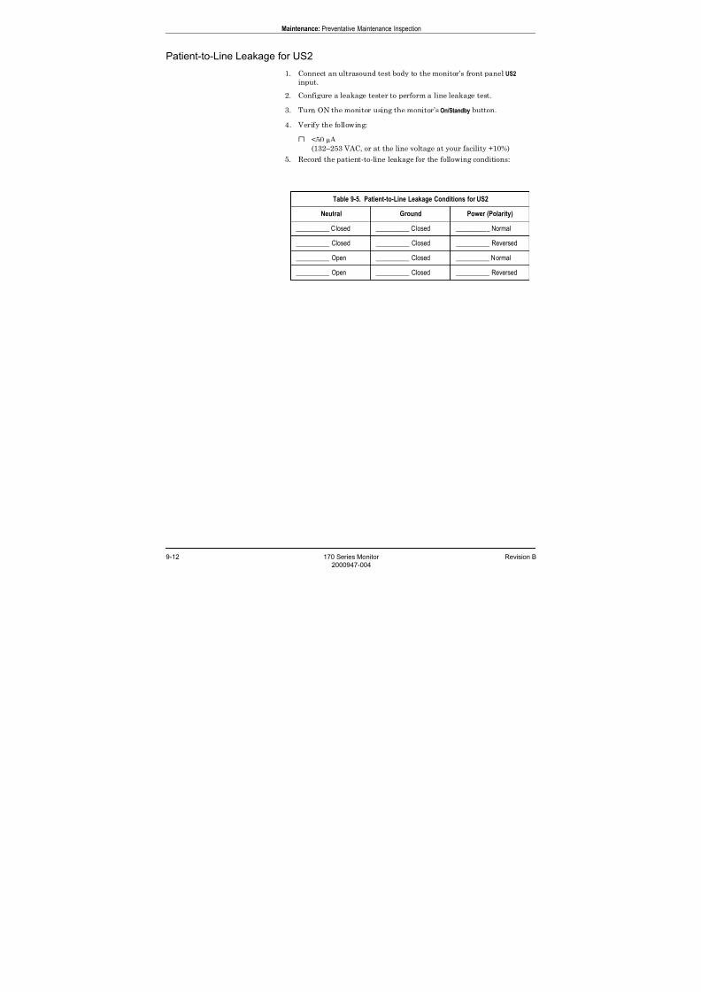
7/25/2019 Serv. Corometrics 170
http://slidepdf.com/reader/full/serv-corometrics-170 212/254
9-12 170 Series Monitor Revision B
2000947-004
Maintenance: Preventative Maintenance Inspection
Patient-to-Line Leakage for US2
1. Connect an ultrasound test body to the monitor’s front panel US2
input.
2. Configure a leakage tester to perform a line leakage test.
3. Turn ON the monitor using the monitor’s On/Standby button.
4. Verify the following:
<50 µ A
(132–253 VAC, or at the line voltage at your facility +10%)
5. Record the patient-to-line leakage for the following conditions:
Table 9-5. Patient-to-Line Leakage Conditions for US2
Neutral Ground Power (Polarity)
__________ Closed __________ Closed __________ Normal
__________ Closed __________ Closed __________ Reversed
__________ Open __________ Closed __________ Normal
__________ Open __________ Closed __________ Reversed
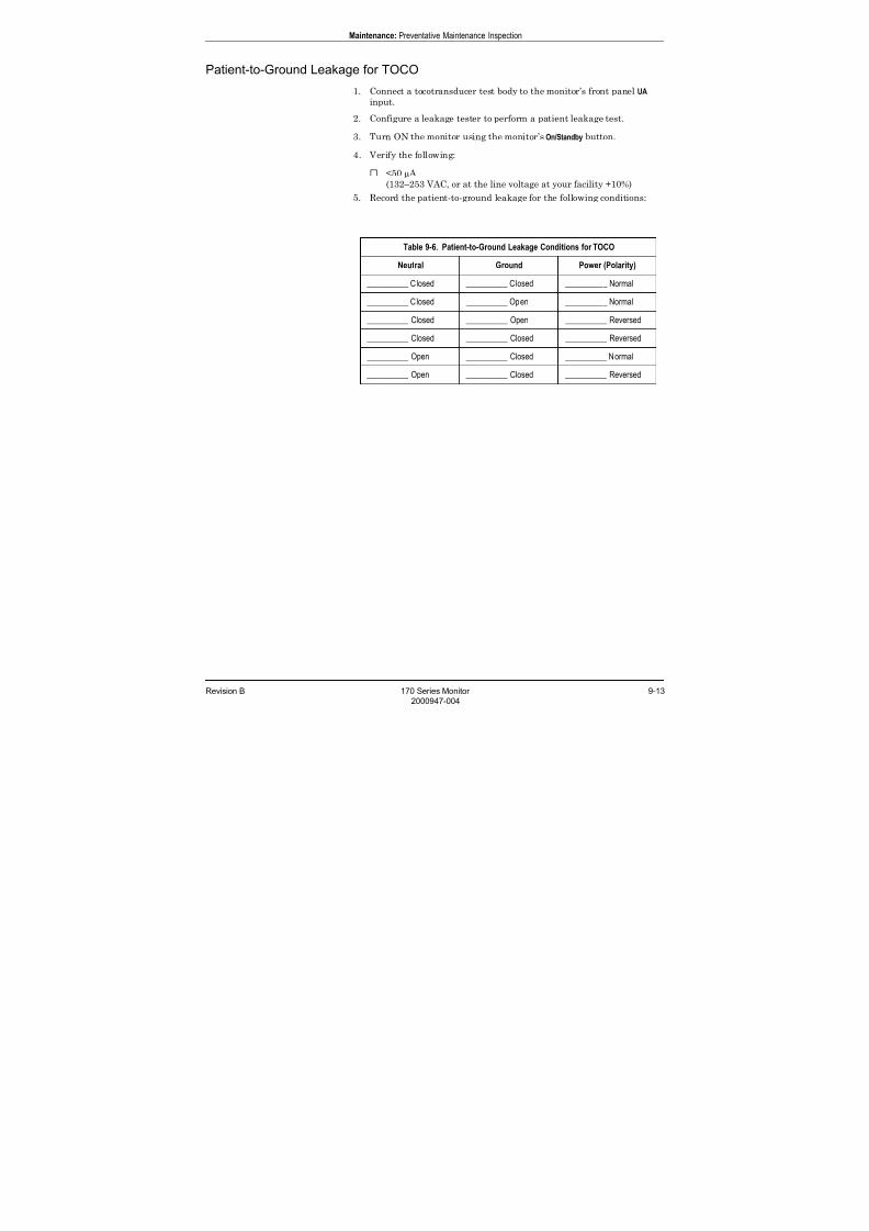
7/25/2019 Serv. Corometrics 170
http://slidepdf.com/reader/full/serv-corometrics-170 213/254
Revision B 170 Series Monitor 9-13
2000947-004
Maintenance: Preventative Maintenance Inspection
Patient-to-Ground Leakage for TOCO
1. Connect a tocotransducer test body to the monitor’s front panel UA
input.
2. Configure a leakage tester to perform a patient leakage test.
3. Turn ON the monitor using the monitor’s On/Standby button.
4. Verify the following:
<50 µ A
(132–253 VAC, or at the line voltage at your facility +10%)
5. Record the patient-to-ground leakage for the following conditions:
Table 9-6. Patient-to-Ground Leakage Conditions for TOCO
Neutral Ground Power (Polarity)
__________ Closed __________ Closed __________ Normal
__________ Closed __________ Open __________ Normal
__________ Closed __________ Open __________ Reversed
__________ Closed __________ Closed __________ Reversed
__________ Open __________ Closed __________ Normal
__________ Open __________ Closed __________ Reversed

7/25/2019 Serv. Corometrics 170
http://slidepdf.com/reader/full/serv-corometrics-170 214/254
9-14 170 Series Monitor Revision B
2000947-004
Maintenance: Preventative Maintenance Inspection
Patient-to-Line Leakage for TOCO
1. Connect a tocotransducer test body to the monitor’s front panel UA
input.
2. Configure a leakage tester to perform a line leakage test.
3. Turn ON the monitor using the monitor’s On/Standby button.
4. Verify the following:
<50 µ A
(132–253 VAC, or at the line voltage at your facility +10%)
5. Record the patient-to-line leakage for the following conditions:
Table 9-7. Patient-to-Line Leakage Conditions for TOCO
Neutral Ground Power (Polarity)
__________ Closed __________ Closed __________ Normal
__________ Closed __________ Closed __________ Reversed
__________ Open __________ Closed __________ Normal
__________ Open __________ Closed __________ Reversed

7/25/2019 Serv. Corometrics 170
http://slidepdf.com/reader/full/serv-corometrics-170 215/254
Revision B 170 Series Monitor 9-15
2000947-004
Maintenance: Preventative Maintenance Inspection
Patient-to-Ground Leakage for IUP
1. Connect an IUP test body to the monitor’s front panel UA input.
2. Configure a leakage tester to perform a patient leakage test.
3. Turn ON the monitor using the monitor’s On/Standby button.
4. Verify the following:
<50 µ A
(132–253 VAC, or at the line voltage at your facility +10%)
5. Record the patient-to-ground leakage for the following conditions:
Table 9-8. Patient-to-Ground Leakage Conditions for IUP
Neutral Ground Power (Polarity)
__________ Closed __________ Closed __________ Normal
__________ Closed __________ Open __________ Normal
__________ Closed __________ Open __________ Reversed
__________ Closed __________ Closed __________ Reversed
__________ Open __________ Closed __________ Normal
__________ Open __________ Closed __________ Reversed

7/25/2019 Serv. Corometrics 170
http://slidepdf.com/reader/full/serv-corometrics-170 216/254
9-16 170 Series Monitor Revision B
2000947-004
Maintenance: Preventative Maintenance Inspection
Patient-to-Line Leakage for IUP
1. Connect an IUP test body to the monitor’s front panel UA input.
2. Configure a leakage tester to perform a line leakage test.
3. Turn ON the monitor using the monitor’s On/Standby button.
4. Verify the following:
<50 µ A
(132–253 VAC, or at the line voltage at your facility +10%)
5. Record the patient-to-line leakage for the following conditions:
Table 9-9. Patient-to-Line Leakage Conditions for IUP
Neutral Ground Power (Polarity)
__________ Closed __________ Closed __________ Normal
__________ Closed __________ Closed __________ Reversed
__________ Open __________ Closed __________ Normal
__________ Open __________ Closed __________ Reversed

7/25/2019 Serv. Corometrics 170
http://slidepdf.com/reader/full/serv-corometrics-170 217/254
Revision B 170 Series Monitor 9-17
2000947-004
Maintenance: Preventative Maintenance Inspection
Patient-to-Ground Leakage for FECG
1. Connect an FECG test body to the monitor’s front panel FECG input.
2. Configure a leakage tester to perform a patient leakage test.
3. Turn ON the monitor using the monitor’s On/Standby button.
4. Verify the following:
<50 µ A
(132–253 VAC, or at the line voltage at your facility +10%)
5. Record the patient-to-ground leakage for the following conditions:
Table 9-10. Patient-to-Ground Leakage Conditions for FECG
Neutral Ground Power (Polarity)
__________ Closed __________ Closed __________ Normal
__________ Closed __________ Open __________ Normal
__________ Closed __________ Open __________ Reversed
__________ Closed __________ Closed __________ Reversed
__________ Open __________ Closed __________ Normal
__________ Open __________ Closed __________ Reversed
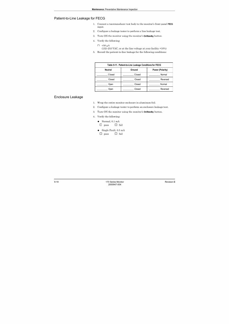
7/25/2019 Serv. Corometrics 170
http://slidepdf.com/reader/full/serv-corometrics-170 218/254
9-18 170 Series Monitor Revision B
2000947-004
Maintenance: Preventative Maintenance Inspection
Patient-to-Line Leakage for FECG
1. Connect a tocotransducer test body to the monitor’s front panel FECG
input.
2. Configure a leakage tester to perform a line leakage test.
3. Turn ON the monitor using the monitor’s On/Standby button.
4. Verify the following:
<50 µ A
(132–253 VAC, or at the line voltage at your facility +10%)
5. Record the patient-to-line leakage for the following conditions:
Enclosure Leakage
1. Wrap the entire monitor enclosure in aluminum foil.
2. Configure a leakage tester to perform an enclosure leakage test.
3. Turn ON the monitor using the monitor’s On/Standby button.
4. Verify the following:
Normal, 0.1 mA
pass fail
Single Fault, 0.5 mA
pass fail
Table 9-11. Patient-to-Line Leakage Conditions for FECG
Neutral Ground Power (Polarity)
__________ Closed __________ Closed __________ Normal
__________ Closed __________ Closed __________ Reversed
__________ Open __________ Closed __________ Normal
__________ Open __________ Closed __________ Reversed
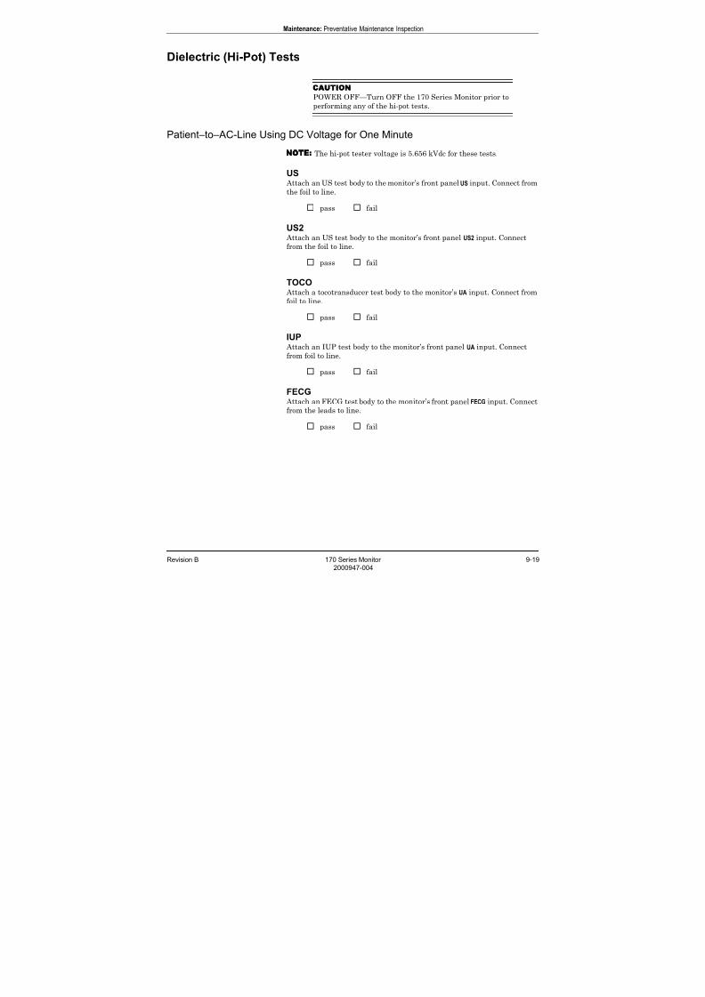
7/25/2019 Serv. Corometrics 170
http://slidepdf.com/reader/full/serv-corometrics-170 219/254
Revision B 170 Series Monitor 9-19
2000947-004
Maintenance: Preventative Maintenance Inspection
Dielectric (Hi-Pot) Tests
CAUTION
POWER OFF—Turn OFF the 170 Series Monitor prior to
performing any of the hi-pot tests.
Patient–to–AC-Line Using DC Voltage for One Minute
NOTE The hi-pot tester voltage is 5.656 kVdc for these tests.
US Attach an US test body to the monitor’s front panel US input. Connect from
the foil to line.
pass fail
US2 Attach an US test body to the monitor’s front panel US2 input. Connect
from the foil to line.
pass fail
TOCO Attach a tocotransducer test body to the monitor’s UA input. Connect from
foil to line.
pass fail
IUP Attach an IUP test body to the monitor’s front panel UA input. Connect
from foil to line.
pass fail
FECG Attach an FECG test body to the monitor’s front panel FECG input. Connect
from the leads to line.
pass fail

7/25/2019 Serv. Corometrics 170
http://slidepdf.com/reader/full/serv-corometrics-170 220/254
9-20 170 Series Monitor Revision B
2000947-004
Maintenance: Preventative Maintenance Inspection
Patient-to-Chassis Using AC Voltage for One Minute
NOTE The hi-pot tester voltage is 2.5 kVAC for these tests.
IMPORTANT
ENCLOSURE—Wrap the entire monitor enclosure inaluminum foil for these tests.
US Attach an US test body to the monitor’s front panel US input. Connect from
the test body foil to the enclosure foil.
pass fail
US2 Attach an US test body to the monitor’s front panel US2 input. Connect
from the test body foil to the enclosure foil.
pass fail
TOCO Attach a tocotransducer test body to the monitor’s UA input. Connect from
the test body foil to the enclosure foil.
pass fail
IUP Attach an IUP test body to the monitor’s front panel UA input. Connect
from the test body foil to the enclosure foil.
pass fail
FECG Attach an FECG test body to the monitor’s front panel FECG input. Connect
from the test body leads to the enclosure foil.
pass fail
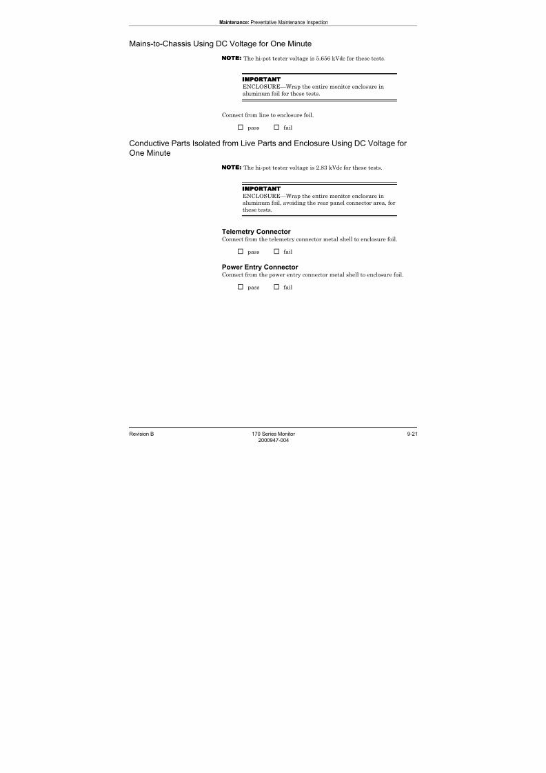
7/25/2019 Serv. Corometrics 170
http://slidepdf.com/reader/full/serv-corometrics-170 221/254
Revision B 170 Series Monitor 9-21
2000947-004
Maintenance: Preventative Maintenance Inspection
Mains-to-Chassis Using DC Voltage for One Minute
NOTE The hi-pot tester voltage is 5.656 kVdc for these tests.
IMPORTANT
ENCLOSURE—Wrap the entire monitor enclosure inaluminum foil for these tests.
Connect from line to enclosure foil.
pass fail
Conductive Parts Isolated from Live Parts and Enclosure Using DC Voltage for
One Minute
NOTE The hi-pot tester voltage is 2.83 kVdc for these tests.
IMPORTANT
ENCLOSURE—Wrap the entire monitor enclosure in
aluminum foil, avoiding the rear panel connector area, for
these tests.
Telemetry Connector Connect from the telemetry connector metal shell to enclosure foil.
pass fail
Power Entry Connector Connect from the power entry connector metal shell to enclosure foil.
pass fail

7/25/2019 Serv. Corometrics 170
http://slidepdf.com/reader/full/serv-corometrics-170 222/254
9-22 170 Series Monitor Revision B
2000947-004
For your notes

7/25/2019 Serv. Corometrics 170
http://slidepdf.com/reader/full/serv-corometrics-170 223/254
Revision B 170 Series Monitor 10-1
2000947-004
Chapter 10
Specifications 10This section contains a detailed list of the technical specifications for the
170 Series Monitor.
This chapter lists specifications for the following:
General Monitor . . . . . . . . . . . . . . . . . . . . . . . . . . . . . . . . . . 10-2
Operating Modes . . . . . . . . . . . . . . . . . . . . . . . . . . . . . . . . . 10-3
Strip Chart Recorder . . . . . . . . . . . . . . . . . . . . . . . . . . . . . . 10-4
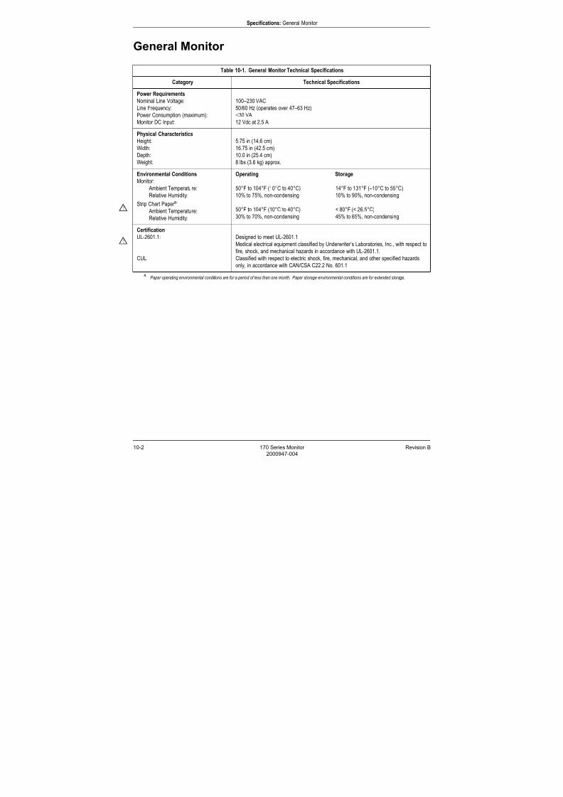
7/25/2019 Serv. Corometrics 170
http://slidepdf.com/reader/full/serv-corometrics-170 224/254
10-2 170 Series Monitor Revision B
2000947-004
Specifications: General Monitor
General Monitor
Table 10-1. General Monitor Technical Specifications
Category Technical Specifications
Power Requirements
Nominal Line Voltage:
Line Frequency:
Power Consumption (maximum):
Monitor DC Input:
100–230 VAC
50/60 Hz (operates over 47–63 Hz)
≤30 VA
12 Vdc at 2.5 A
Physical Characteristics
Height:
Width:
Depth:
Weight:
5.75 in (14.6 cm)
16.75 in (42.5 cm)
10.0 in (25.4 cm)
8 lbs (3.6 kg) approx.
Environmental Conditions
Monitor: Ambient Temperature:
Relative Humidity:
Strip Chart Paper a:
Ambient Temperature:
Relative Humidity:
aPaper operating environmental conditions are for a period of less than one month. Paper storage environmental conditions are for extended storage.
Operating Storage
50°F to 104°F (10°C to 40°C) 14°F to 131°F (–10°C to 55°C)
10% to 75%, non-condensing 10% to 90%, non-condensing
50°F to 104°F (10°C to 40°C) < 80°F (< 26.5°C)
30% to 70%, non-condensing 45% to 65%, non-condensing
Certification
UL-2601.1:
CUL:
Designed to meet UL-2601.1
Medical electrical equipment classified by Underwriter’s Laboratories, Inc., with respect to
fire, shock, and mechanical hazards in accordance with UL-2601.1.
Classified with respect to electric shock, fire, mechanical, and other specified hazards
only, in accordance with CAN/CSA C22.2 No. 601.1
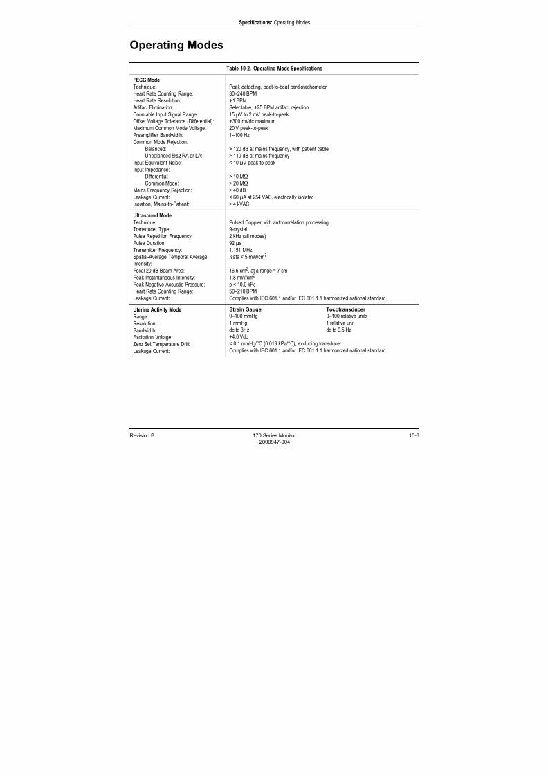
7/25/2019 Serv. Corometrics 170
http://slidepdf.com/reader/full/serv-corometrics-170 225/254
Revision B 170 Series Monitor 10-3
2000947-004
Specifications: Operating Modes
Operating Modes
Table 10-2. Operating Mode Specifications
FECG Mode
Technique:Heart Rate Counting Range:
Heart Rate Resolution:
Artifact Elimination:
Countable Input Signal Range:
Offset Voltage Tolerance (Differential):
Maximum Common Mode Voltage:
Preamplifier Bandwidth:
Common Mode Rejection:
Balanced:
Unbalanced 5kΩ RA or LA:
Input Equivalent Noise:
Input Impedance:
Differential:Common Mode:
Mains Frequency Rejection:
Leakage Current:
Isolation, Mains-to-Patient:
Peak detecting, beat-to-beat cardiotachometer 30–240 BPM
±1 BPM
Selectable, ±25 BPM artifact rejection
15 µV to 2 mV peak-to-peak
±300 mVdc maximum
20 V peak-to-peak
1–100 Hz
> 120 dB at mains frequency, with patient cable
> 110 dB at mains frequency
< 10 µV peak-to-peak
> 10 MΩ> 20 MΩ
> 40 dB
< 60 µ A at 254 VAC, electrical ly isolated
> 4 kVAC
Ultrasound Mode
Technique:
Transducer Type:
Pulse Repetition Frequency:
Pulse Duration:
Transmitter Frequency:
Spatial-Average Temporal Average
Intensity:Focal 20 dB Beam Area:
Peak Instantaneous Intensity:
Peak-Negative Acoustic Pressure:
Heart Rate Counting Range:
Leakage Current:
Pulsed Doppler with autocorrelation processing
9-crystal
2 kHz (all modes)
92 µs
1.151 MHz
Isata < 5 mW/cm2
16.6 cm2, at a range = 7 cm
1.8 mW/cm2
p < 10.0 kPa
50–210 BPM
Complies with IEC 601.1 and/or IEC 601.1.1 harmonized national standard
Uterine Activity Mode
Range:
Resolution:
Bandwidth:
Excitation Voltage:
Zero Set Temperature Drift:
Leakage Current:
Strain Gauge Tocotransducer
0–100 mmHg 0–100 relative units
1 mmHg 1 relative unit
dc to 3Hz dc to 0.5 Hz
+4.0 Vdc
< 0.1 mmHg/°C (0.013 kPa/°C), excluding transducer
Complies with IEC 601.1 and/or IEC 601.1.1 harmonized national standard

7/25/2019 Serv. Corometrics 170
http://slidepdf.com/reader/full/serv-corometrics-170 226/254
10-4 170 Series Monitor Revision B
2000947-004
Specifications: Strip Chart Recorder
Strip Chart Recorder
NOTE Specifications are subject to change without notice.
Table 10-3. Strip Chart Recorder Technical Specifications
Heart Rate Scale
Chart Width:Scaling:
Range:
Resolution:
Domestic International
7 cm 8 cm30 BPM/cm 20 BPM/cm
30–240 BPM 50–210 BPM
1 BPM 1 BPM
Uterine Activity Scale
Chart Width:
Scaling:
Range:
Resolution:
Strain Gauge Tocotransducer
4 cm 4 cm
25 mmHg/cm 25 relative units/cm
0–100 mmHg 0–100 relative units
1 mmHg 1 relative unit
Recorder Drive
Speeds:
Speed Accuracy:
1, 2, and 3 cm/min
±1 %

7/25/2019 Serv. Corometrics 170
http://slidepdf.com/reader/full/serv-corometrics-170 227/254
Revision B 170 Series Monitor 11-1
2000947-004
Chapter 11
Parts Lists 11This chapter of the manual provides parts lists and block diagrams.
NOTE
GE makes every effort possible to provide the most up-to-date
reference documentation for your Corometrics equipment.
However, in special cases involving field-installed upgrades, adrawing or parts list in this manual may not reflect the revision
level of your unit’s subassemblies. When discrepancies are
found, contact the GE Service Department at one of the numbers
found on the back cover of this manual.
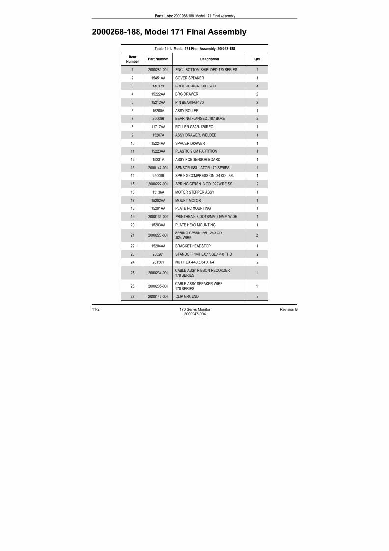
7/25/2019 Serv. Corometrics 170
http://slidepdf.com/reader/full/serv-corometrics-170 228/254
11-2 170 Series Monitor Revision B
2000947-004
Parts Lists: 2000268-188, Model 171 Final Assembly
2000268-188, Model 171 Final Assembly
Table 11-1. Model 171 Final Assembly, 200268-188
Item
Number Part Number Description Qty
1 2000281-001 ENCL BOTTOM SHIELDED 170 SERIES 1
2 15451AA COVER SPEAKER 1
3 140173 FOOT RUBBER .50D .26H 4
4 15222AA BRG DRAWER 2
5 15212AA PIN BEARING-170 2
6 15200A ASSY ROLLER 1
7 250096 BEARING,FLANGED,.187 BORE 2
8 11717AA ROLLER GEAR-120REC 1
9 15207A ASSY DRAWER, WELDED 1
10 15224AA SPACER DRAWER 1
11 15223AA PLASTIC 9 CM PARTITION 1
12 15231A ASSY PCB SENSOR BOARD 1
13 2000147-001 SENSOR INSULATOR 170 SERIES 1
14 250099 SPRING COMPRESSION,.24 OD,,.38L 1
15 2000222-001 SPRING CPRSN .3 OD .022WIRE SS 2
16 15136A MOTOR STEPPER ASSY 1
17 15202AA MOUNT MOTOR 1
18 15201AA PLATE PC MOUNTING 1
19 2000133-001 PRINTHEAD 8 DOTS/MM 216MM WIDE 1
20 15203AA PLATE HEAD MOUNTING 1
21 2000223-001SPRING CPRSN .56L .240 OD
.024 WIRE2
22 15204AA BRACKET HEADSTOP 1
23 280201 STANDOFF,1/4HEX,1/8SL,4-4,0 THD 2
24 281501 NUT,HEX,4-40,5/64 X 1/4 2
25 2000234-001CABLE ASSY RIBBON RECORDER
170 SERIES1
26 2000235-001CABLE ASSY SPEAKER WIRE
170 SERIES1
27 2000146-001 CLIP GROUND 2
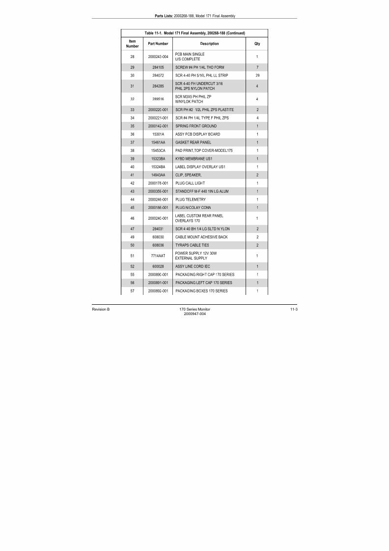
7/25/2019 Serv. Corometrics 170
http://slidepdf.com/reader/full/serv-corometrics-170 229/254
Revision B 170 Series Monitor 11-3
2000947-004
Parts Lists: 2000268-188, Model 171 Final Assembly
28 2000243-004PCB MAIN SINGLE
U/S COMPLETE1
29 284105 SCREW #4 PH 1/4L THD FORM 7
30 284072 SCR 4-40 PH 5/16L PHL LL STRIP 29
31 284285SCR 4-40 FH UNDERCUT 3/16
PHIL 2PS NYLON PATCH4
32 289516SCR M3X5 PH PHIL ZP
W/NYLOK PATCH4
33 2000220-001 SCR PH #2 1/2L PHIL ZPS PLASTITE 2
34 2000221-001 SCR #4 PH 1/4L TYPE F PHIL ZPS 4
35 2000142-001 SPRING FRONT GROUND 1
36 15301A ASSY PCB DISPLAY BOARD 1
37 15461AA GASKET REAR PANEL 1
38 15453CA PAD PRINT,TOP COVER-MODEL175 1
39 15323BA KYBD MEMBRANE US1 1
40 15324BA LABEL DISPLAY OVERLAY US1 1
41 14943AA CLIP, SPEAKER, 2
42 2000178-001 PLUG CALL LIGHT 1
43 2000359-001 STANDOFF M-F 440 1IN LG ALUM 1
44 2000246-001 PLUG TELEMETRY 1
45 2000186-001 PLUG NICOLAY CONN 1
46 2000240-001LABEL CUSTOM REAR PANEL
OVERLAYS 1701
47 284031 SCR 4-40 BH 1/4 LG SLTD N YLON 2
49 608030 CABLE MOUNT ADHESIVE BACK 2
50 608036 TYRAPS CABLE TIES 2
51 7714AATPOWER SUPPLY 12V 30W
EXTERNAL SUPPLY1
52 600028 ASSY LINE CORD IEC 1
55 2000890-001 PACKAGING RIGHT CAP 170 SERIES 1
56 2000891-001 PACKAGING LEFT CAP 170 SERIES 1
57 2000892-001 PACKAGING BOXES 170 SERIES 1
Table 11-1. Model 171 Final Assembly, 200268-188 (Continued)
Item
Number Part Number Description Qty

7/25/2019 Serv. Corometrics 170
http://slidepdf.com/reader/full/serv-corometrics-170 230/254
11-4 170 Series Monitor Revision B
2000947-004
Parts Lists: 2000268-188, Model 171 Final Assembly
58 2000893-001PACKAGING SLOTTED TRAY
170 SERIES1
59 13984AA LBL PACKING LIST 340 1
60 2000555-001 SHLD SPEAKER - 170 1
61 410066 POLY BAG 23X26X.006 1
62 410097 TAPE SHIPPING 3IN WIDE 4
63 4281CA LBL SERIAL# UL APPV’D-155 1
64 4281DA LABEL C-UL HAZZARD TAG120 SERIES 1
Table 11-1. Model 171 Final Assembly, 200268-188 (Continued)
Item
Number Part Number Description Qty

7/25/2019 Serv. Corometrics 170
http://slidepdf.com/reader/full/serv-corometrics-170 231/254
Revision B 170 Series Monitor 11-5
2000947-004
Parts Lists: 2000268-189, Model 172 Final Assembly
2000268-189, Model 172 Final Assembly
Table 11-2. Model 172 Final Assembly, 2000268-189
Item
Number Part Number Description Qty
1 2000281-001 ENCL BOTTOM SHIELDED 170 SERIES 1
2 15451AA COVER SPEAKER 1
3 140173 FOOT RUBBER .50D .26H 4
4 15222AA BRG DRAWER 2
5 15212AA PIN BEARING-170 2
6 15200A ASSY ROLLER 1
7 250096 BEARING FLANGED .187 BORE 2
8 11717AA ROLLER GEAR-120REC 1
9 15207A ASSY DRAWER WELDED 1
10 15224AA SPACER DRAWER 1
11 15223AA PLASTIC 9 CM PARTITION 1
12 15231A ASSY PCB SENSOR BOARD 1
13 2000147-001 SENSOR INSULATOR 170 SERIES 1
14 250099 SPRING COMPRESSION .24 OD .38L 1
15 2000222-001 SPRING CPRSN .3 OD .022WIRE SS 2
16 15136A MOTOR STEPPER ASSY 1
17 15202AA MOUNT MOTOR 1
18 15201AA PLATE PC MOUNTING 1
19 2000133-001 PRINTHEAD 8 DOTS/MM 216MM WIDE 1
20 15203AA PLATE HEAD MOUNTING 1
21 2000223-001SPRING CPRSN .56L .240 OD
.024 WIRE2
22 15204AA BRACKET HEADSTOP 1
23 280201 STANDOFF 1/4HEX 1/8SL 4-4 0 THD 2
24 281501 NUT HEX 4-40 5/64 X 1/4 2
25 2000234-001CABLE ASSY RIBBON RECORDER
170 SERIES1
26 2000235-001CABLE ASSY SPEAKER WIRE
170 SERIES1
27 2000146-001 CLIP GROUND 2

7/25/2019 Serv. Corometrics 170
http://slidepdf.com/reader/full/serv-corometrics-170 232/254
11-6 170 Series Monitor Revision B
2000947-004
Parts Lists: 2000268-189, Model 172 Final Assembly
28 15269EPCB ASSY MAIN PCB
DUAL US COMP1
29 284105 SCREW #4 PH 1/4L THD FORM 7
30 284072 SCR 4-40 PH 5/16L PHL LL STRIP 29
31 284285SCR 4-40 FH UNDERCUT 3/16 PHIL 2PS
NYLON PATCH4
32 289516SCR M3X5 PH PHIL ZP
W/NYLOK PATCH4
33 2000220-001 SCR PH #2 1/2L PHIL ZPS PLASTITE 2
34 2000221-001 SCR #4 PH 1/4L TYPE F PHIL ZPS 6
35 2000142-001 SPRING FRONT GROUND 1
36 15301A ASSY PCB DISPLAY BOARD 1
37 15461AA GASKET REAR PANEL 1
38 15453AA PAD PRINT TOP COVER-MODEL 170 1
39 15323AA KYBD MEMBRANE US2 1
40 15324AA LABEL DISPLAY OVERLAY US2 1
41 14943AA CLIP SPEAKER 2
42 2000178-001 PLUG CALL LIGHT 1
43 2000359-001 STANDOFF M-F 440 1IN LG ALUM 1
44 2000246-001 PLUG TELEMETRY 1
46 2000240-001LABEL CUSTOM REAR PANEL
OVERLAYS 1701
47 284031 SCR 4-40 BH 1/4 LG SLTD N YLON 2
49 608030 CABLE MOUNT ADHESIVE BACK 2
50 608036 TYRAPS CABLE TIES 2
51 7714AAT
POWER SUPPLY 12V 30W
EXTERNAL SUPPLY 1
52 600028 ASSY LINE CORD IEC 1
55 2000890-001 PACKAGING RIGHT CAP 170 SERIES 1
56 2000891-001 PACKAGING LEFT CAP 170 SERIES 1
57 2000892-001 PACKAGING BOXES 170 SERIES 1
58 2000893-001PACKAGING SLOTTED TRAY
170 SERIES
1
Table 11-2. Model 172 Final Assembly, 2000268-189 (Continued)
Item
Number Part Number Description Qty
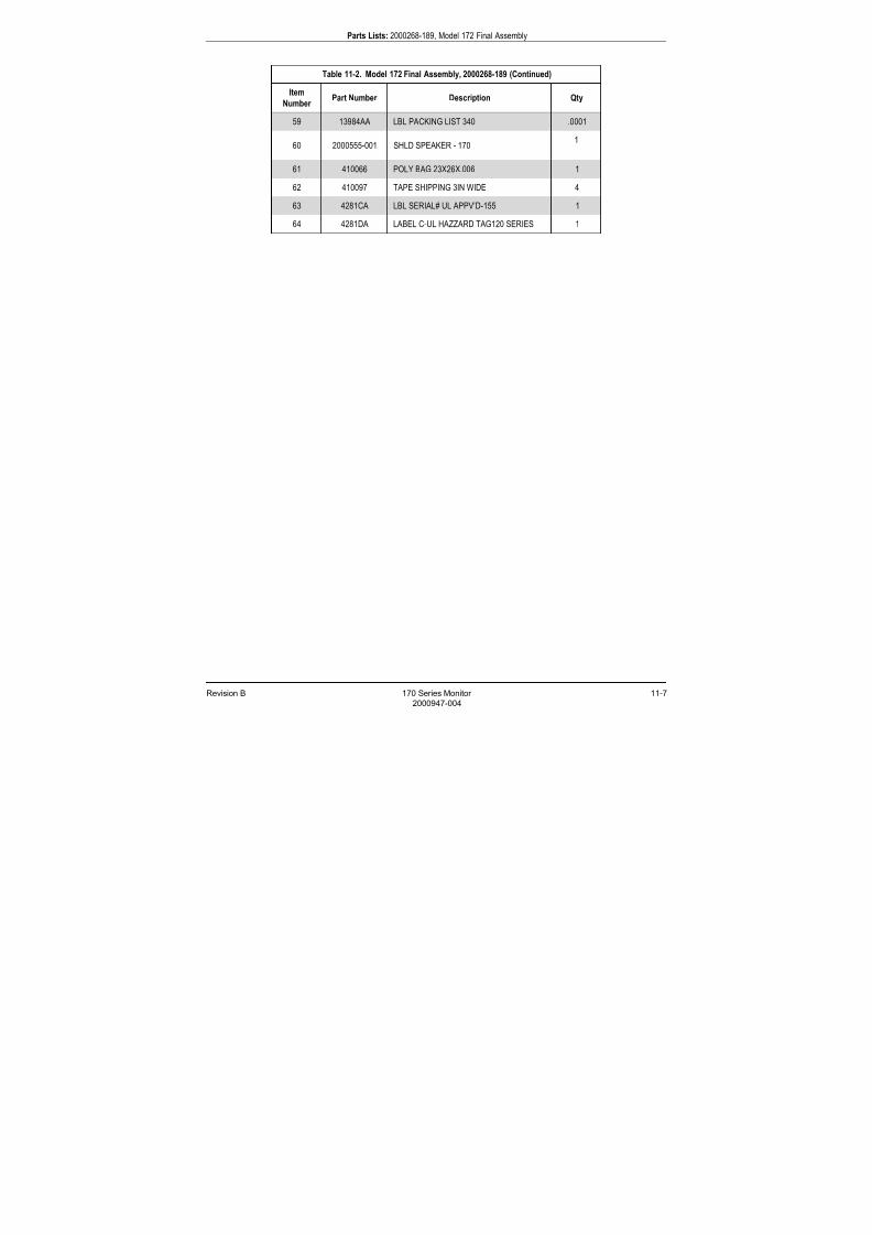
7/25/2019 Serv. Corometrics 170
http://slidepdf.com/reader/full/serv-corometrics-170 233/254
Revision B 170 Series Monitor 11-7
2000947-004
Parts Lists: 2000268-189, Model 172 Final Assembly
59 13984AA LBL PACKING LIST 340 .0001
60 2000555-001 SHLD SPEAKER - 170 1
61 410066 POLY BAG 23X26X.006 1
62 410097 TAPE SHIPPING 3IN WIDE 4
63 4281CA LBL SERIAL# UL APPV’D-155 1
64 4281DA LABEL C-UL HAZZARD TAG120 SERIES 1
Table 11-2. Model 172 Final Assembly, 2000268-189 (Continued)
Item
Number Part Number Description Qty
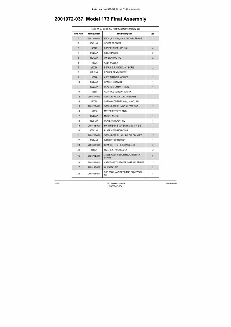
7/25/2019 Serv. Corometrics 170
http://slidepdf.com/reader/full/serv-corometrics-170 234/254
11-8 170 Series Monitor Revision B
2000947-004
Parts Lists: 2001972-037, Model 173 Final Assembly
2001972-037, Model 173 Final Assembly
Table 11-3. Model 173 Final Assembly, 2001972-037
Find Num Item Number Item Description Qty
1 2007385-001 ENCL ,BOTTOM, SHIELDED-170 SERIES 1
2 15451AA COVER SPEAKER 1
3 140173 FOOT RUBBER .50D .26H 4
4 15222AA BRG DRAWER 2
5 15212AA PIN BEARING-170 2
6 15200A ASSY ROLLER 1
7 250096 BEARING,FLANGED,.187 BORE, 2
8 11717AA ROLLER GEAR-120REC, 1
9 15207A ASSY DRAWER, WELDED 1
10 15224AA SPACER DRAWER 1
11 15223AA PLASTIC 9 CM PARTITION 1
12 15231A ASSY PCB SENSOR BOARD 1
13 2000147-001 SENSOR INSULATOR 170 SERIES 1
14 250099 SPRING COMPRESSION,.24 OD,,.38L 1
15 2000222-001 SPRING CPRSN .3 OD .022WIRE SS 2
16 15136A MOTOR STEPPER ASSY 1
17 15202AA MOUNT MOTOR 1
18 15201AA PLATE PC MOUNTING 1
19 2000133-001 PRINTHEAD 8 DOTS/MM 216MM WIDE 1
20 15203AA PLATE HEAD MOUNTING 1
21 2000223-001 SPRING CPRSN .56L .240 OD .024 WIRE 2
22 15204AA BRACKET HEADSTOP 1
23 2002433-001 STANDOFF 1/4 HEX SWAGE 4-40 2
24 281501 NUT,HEX,4-40,3/32 X 1/4 2
25 2000234-001CABLE ASSY RIBBON RECORDER 170
SERIES1
26 2000235-001 CABLE ASSY SPEAKER WIRE 170 SERIES 1
27 2000146-001 CLIP GROUND 2
28 2000324-007PCB ASSY MAIN FECG/PRS COMP V3.20-
1731
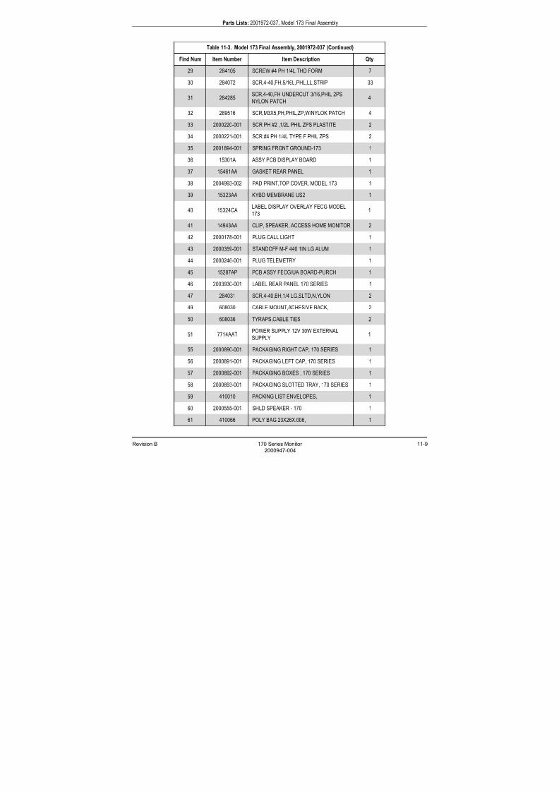
7/25/2019 Serv. Corometrics 170
http://slidepdf.com/reader/full/serv-corometrics-170 235/254
Revision B 170 Series Monitor 11-9
2000947-004
Parts Lists: 2001972-037, Model 173 Final Assembly
29 284105 SCREW #4 PH 1/4L THD FORM 7
30 284072 SCR,4-40,PH,5/16L,PHL,LL,STRIP 33
31 284285SCR,4-40,FH UNDERCUT 3/16,PHIL 2PS
NYLON PATCH4
32 289516 SCR,M3X5,PH,PHIL,ZP,W/NYLOK PATCH 4
33 2000220-001 SCR PH #2 ,1/2L PHIL ZPS PLASTITE 2
34 2000221-001 SCR #4 PH 1/4L TYPE F PHIL ZPS 2
35 2001894-001 SPRING FRONT GROUND-173 1
36 15301A ASSY PCB DISPLAY BOARD 1
37 15461AA GASKET REAR PANEL 1
38 2004993-002 PAD PRINT,TOP COVER, MODEL 173 1
39 15323AA KYBD MEMBRANE US2 1
40 15324CALABEL DISPLAY OVERLAY FECG MODEL
1731
41 14943AA CLIP, SPEAKER, ACCESS HOME MONITOR 2
42 2000178-001 PLUG CALL LIGHT 1
43 2000359-001 STANDOFF M-F 440 1IN LG ALUM 1
44 2000246-001 PLUG TELEMETRY 1
45 15287AP PCB ASSY FECG/UA BOARD-PURCH 1
46 2003930-001 LABEL REAR PANEL 170 SERIES 1
47 284031 SCR,4-40,BH,1/4 LG,SLTD,N,YLON 2
49 608030 CABLE MOUNT,ADHESIVE BACK, 2
50 608036 TYRAPS,CABLE TIES 2
51 7714AATPOWER SUPPLY 12V 30W EXTERNAL
SUPPLY1
55 2000890-001 PACKAGING RIGHT CAP, 170 SERIES 1
56 2000891-001 PACKAGING LEFT CAP, 170 SERIES 1
57 2000892-001 PACKAGING BOXES , 170 SERIES 1
58 2000893-001 PACKAGING SLOTTED TRAY, 170 SERIES 1
59 410010 PACKING LIST ENVELOPES, 1
60 2000555-001 SHLD SPEAKER - 170 1
61 410066 POLY BAG 23X26X.006, 1
Table 11-3. Model 173 Final Assembly, 2001972-037 (Continued)
Find Num Item Number Item Description Qty
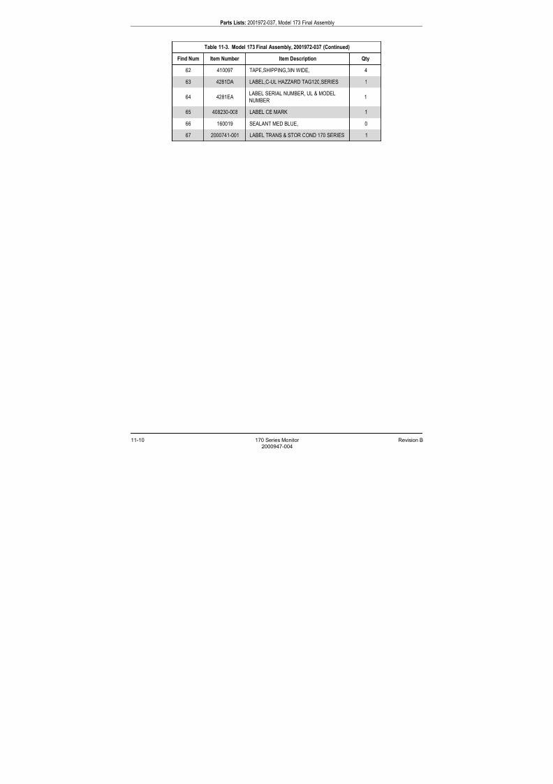
7/25/2019 Serv. Corometrics 170
http://slidepdf.com/reader/full/serv-corometrics-170 236/254
11-10 170 Series Monitor Revision B
2000947-004
Parts Lists: 2001972-037, Model 173 Final Assembly
62 410097 TAPE,SHIPPING,3IN WIDE, 4
63 4281DA LABEL,C-UL HAZZARD TAG120,SERIES 1
64 4281EALABEL SERIAL NUMBER, UL & MODEL
NUMBER1
65 408230-008 LABEL CE MARK 1
66 160019 SEALANT MED BLUE, 0
67 2000741-001 LABEL TRANS & STOR COND 170 SERIES 1
Table 11-3. Model 173 Final Assembly, 2001972-037 (Continued)
Find Num Item Number Item Description Qty

7/25/2019 Serv. Corometrics 170
http://slidepdf.com/reader/full/serv-corometrics-170 237/254
Revision B 170 Series Monitor 11-11
2000947-004
Parts Lists: 2001972-038, Model 174 Final Assembly
2001972-038, Model 174 Final Assembly
Table 11-4. Model 174 Final Assembly, 2001972-038
Find Num Item Number Item Description Qty
1 2007385-001 ENCL ,BOTTOM, SHIELDED-170 SERIES 1
2 15451AA COVER SPEAKER 1
3 140173 FOOT RUBBER .50D .26H 4
4 15222AA BRG DRAWER 2
5 15212AA PIN BEARING-170 2
6 15200A ASSY ROLLER 1
7 250096 BEARING,FLANGED,.187 BORE, 2
8 11717AA ROLLER GEAR-120REC, 1
9 15207A ASSY DRAWER, WELDED 1
10 15224AA SPACER DRAWER 1
11 15223AA PLASTIC 9 CM PARTITION 1
12 15231A ASSY PCB SENSOR BOARD 1
13 2000147-001 SENSOR INSULATOR 170 SERIES 1
14 250099 SPRING COMPRESSION,.24 OD,,.38L 1
15 2000222-001 SPRING CPRSN .3 OD .022WIRE SS 2
16 15136A MOTOR STEPPER ASSY 1
17 15202AA MOUNT MOTOR 1
18 15201AA PLATE PC MOUNTING 1
19 2000133-001 PRINTHEAD 8 DOTS/MM 216MM WIDE 1
20 15203AA PLATE HEAD MOUNTING 1
21 2000223-001 SPRING CPRSN .56L .240 OD .024 WIRE 2
22 15204AA BRACKET HEADSTOP 1
23 2002433-001 STANDOFF 1/4 HEX SWAGE 4-40 2
24 281501 NUT,HEX,4-40,3/32 X 1/4 2
25 2000234-001CABLE ASSY RIBBON RECORDER 170
SERIES1
26 2000235-001 CABLE ASSY SPEAKER WIRE 170 SERIES 1
27 2000146-001 CLIP GROUND 2
28 2000973-005 PCB ASSY MAIN FECG/PRS DUAL U/S-174 1
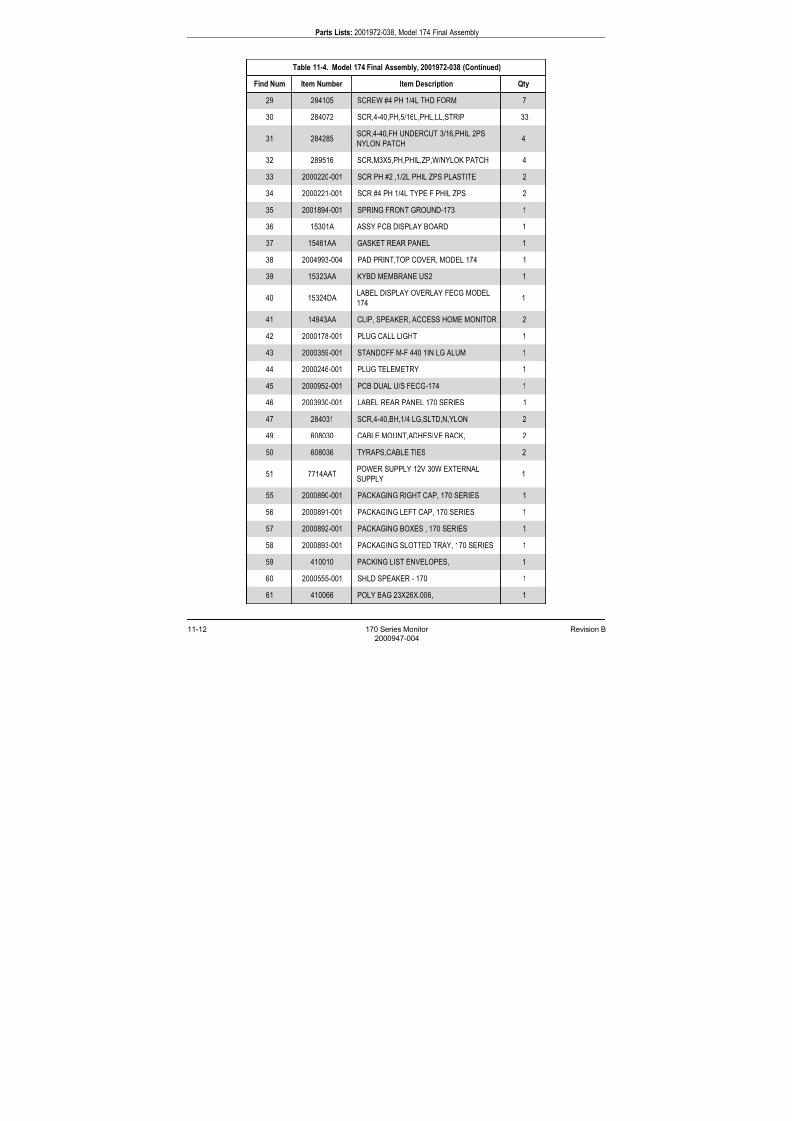
7/25/2019 Serv. Corometrics 170
http://slidepdf.com/reader/full/serv-corometrics-170 238/254
11-12 170 Series Monitor Revision B
2000947-004
Parts Lists: 2001972-038, Model 174 Final Assembly
29 284105 SCREW #4 PH 1/4L THD FORM 7
30 284072 SCR,4-40,PH,5/16L,PHL,LL,STRIP 33
31 284285SCR,4-40,FH UNDERCUT 3/16,PHIL 2PS
NYLON PATCH4
32 289516 SCR,M3X5,PH,PHIL,ZP,W/NYLOK PATCH 4
33 2000220-001 SCR PH #2 ,1/2L PHIL ZPS PLASTITE 2
34 2000221-001 SCR #4 PH 1/4L TYPE F PHIL ZPS 2
35 2001894-001 SPRING FRONT GROUND-173 1
36 15301A ASSY PCB DISPLAY BOARD 1
37 15461AA GASKET REAR PANEL 1
38 2004993-004 PAD PRINT,TOP COVER, MODEL 174 1
39 15323AA KYBD MEMBRANE US2 1
40 15324DALABEL DISPLAY OVERLAY FECG MODEL
1741
41 14943AA CLIP, SPEAKER, ACCESS HOME MONITOR 2
42 2000178-001 PLUG CALL LIGHT 1
43 2000359-001 STANDOFF M-F 440 1IN LG ALUM 1
44 2000246-001 PLUG TELEMETRY 1
45 2000952-001 PCB DUAL U/S FECG-174 1
46 2003930-001 LABEL REAR PANEL 170 SERIES 1
47 284031 SCR,4-40,BH,1/4 LG,SLTD,N,YLON 2
49 608030 CABLE MOUNT,ADHESIVE BACK, 2
50 608036 TYRAPS,CABLE TIES 2
51 7714AATPOWER SUPPLY 12V 30W EXTERNAL
SUPPLY1
55 2000890-001 PACKAGING RIGHT CAP, 170 SERIES 1
56 2000891-001 PACKAGING LEFT CAP, 170 SERIES 1
57 2000892-001 PACKAGING BOXES , 170 SERIES 1
58 2000893-001 PACKAGING SLOTTED TRAY, 170 SERIES 1
59 410010 PACKING LIST ENVELOPES, 1
60 2000555-001 SHLD SPEAKER - 170 1
61 410066 POLY BAG 23X26X.006, 1
Table 11-4. Model 174 Final Assembly, 2001972-038 (Continued)
Find Num Item Number Item Description Qty

7/25/2019 Serv. Corometrics 170
http://slidepdf.com/reader/full/serv-corometrics-170 239/254
Revision B 170 Series Monitor 11-13
2000947-004
Parts Lists: 2001972-038, Model 174 Final Assembly
62 410097 TAPE,SHIPPING,3IN WIDE, 4
63 4281DA LABEL,C-UL HAZZARD TAG120,SERIES 1
64 4281EALABEL SERIAL NUMBER, UL & MODEL
NUMBER1
65 408230-008 LABEL CE MARK 1
66 160019 SEALANT MED BLUE, 0
67 2000741-001 LABEL TRANS & STOR COND 170 SERIES 1
Table 11-4. Model 174 Final Assembly, 2001972-038 (Continued)
Find Num Item Number Item Description Qty

7/25/2019 Serv. Corometrics 170
http://slidepdf.com/reader/full/serv-corometrics-170 240/254
11-14 170 Series Monitor Revision B
2000947-004
Parts Lists: 2264AAX, Button-Style Nautilus Tocotranducer Assembly Parts List (5-ft cord)
2264AAX, Button-Style Nautilus TocotranducerAssembly Parts List (5-ft cord)
Table 11-5. 2264AAX, Button-Style Nautilus Tocotransducer Assembly Parts List (5-ft cord)
Find
NumItem Number Item Description Qty
1 14894A TOCO CBL ASSY OB 5' LG,WATERTIGHT 1
4 15079AA MARKING CASE BUTTON TOP-TOCO,WATERTIGHT 1
6 14790B CASE BOTTOM ASSY TOCO OB,WATERTIGHT 1
7 14594AA FLAT SEAL TOCO U/S WATERTIGHT XDCR 1
8 14640AA CABLE MOUNTING NUT TOCO US WATERTIGHT 1
9 284106 SCR,4-40,PH,5/16L,W/SEAL,PHIL,SS,LL 5
10 14638AA SCREW CAP WATERTIGHT 4
11 15254AA SCREW CAP FLAT MARING,WATERTIGHT SCUCERS 1
12 7529DA KNOB,TOCO-KNOB TOP XDCR K,IT116 1
13 281260 SCR SET 2-56 1/8L OVAL PT SS 1
17 8974AA ABD STRAP-BUTTON STYLE BE,LT 1
18 14855AA WARNING TAG CABLES WATERTIGHT 1
19 13658FA LBL,CE,CAUTION IP68,WATERTIGHT XDCR 1
20 440011 LABEL,2.25X.75,SELF-LAM,WHITE 121 4991AA ACC PACKER, 1
22 410069 PACK MATERIAL ST 1
23 410112 BAG,AIRCAP, 6 X 8-1/2, 1
24 15264AA SHIPPING LBL, 2264AAX WATERTIGHT XDUCERS 1
30 13434AA LBL,SHIP CRTN CE MARK-VAR, 1
31 160034 LOCTITE,SUPERBONDE, 0
32 162004 OIL,SILICONE,3ML TUBE, 0
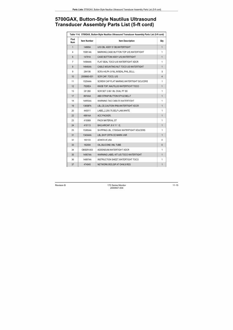
7/25/2019 Serv. Corometrics 170
http://slidepdf.com/reader/full/serv-corometrics-170 241/254
Revision B 170 Series Monitor 11-15
2000947-004
Parts Lists: 5700GAX, Button-Style Nautilus Ultrasound Transducer Assembly Parts List (5-ft cord)
5700GAX, Button-Style Nautilus UltrasoundTransducer Assembly Parts List (5-ft cord)
Table 11-6. 5700GAX, Button-Style Nautilus Ultrasound Transducer Assembly Parts List (5-ft cord)
Find
NumItem Number Item Description Qty
1 14895A U/S CBL ASSY 5' OB,WATERTIGHT 1
4 15081AA MARKING,CASE BUTTON TOP U/S,WATERTIGHT 1
6 14791A CASE BOTTOM ASSY U/S,WATERTIGHT 1
7 14594AA FLAT SEAL TOCO U/S WATERTIGHT XDCR 1
8 14640AA CABLE MOUNTING NUT TOCO US WATERTIGHT 1
9 284106 SCR,4-40,PH,5/16L,W/SEAL,PHIL,SS,LL 5
10 2008660-001 SCR CAP, TOCO, U/S 4
11 15254AA SCREW CAP FLAT MARING,WATERTIGHT SCUCERS 1
12 7529EA KNOB TOP, NAUTILUS WATERTIGHT TOCO 1
13 281260 SCR SET 2-56 1/8L OVAL PT SS 1
17 8974AA ABD STRAP-BUTTON STYLE BE,LT 1
18 14855AA WARNING TAG CABLES WATERTIGHT 1
19 13658FA LBL,CE,CAUTION IP68,WATERTIGHT XDCR 1
20 440011 LABEL,2.25X.75,SELF-LAM,WHITE 122 4991AA ACC PACKER, 1
23 410069 PACK MATERIAL ST 1
24 410113 BAG,AIRCAP, 8 X 11-1/2, 1
25 15265AA SHIPPING LBL, 5700GAX WATERTIGHT XDUCERS 1
31 13434AA LBL,SHIP CRTN CE MARK-VAR 1
32 160103 ADHESIVE,454 0
33 162004 OIL,SILICONE,3ML TUBE 0
34 OBSER-003 ADDENDUM,WATERTIGHT XDCR 1
35 14957AA WARNING LABEL KIT U/S TOCO WATERTIGHT 1
36 14897AA INSTRUCTION SHEET,WATERTIGHT TOCO 1
37 474045 NETWORK,RES,SIP,47 OHM,9,RES 1
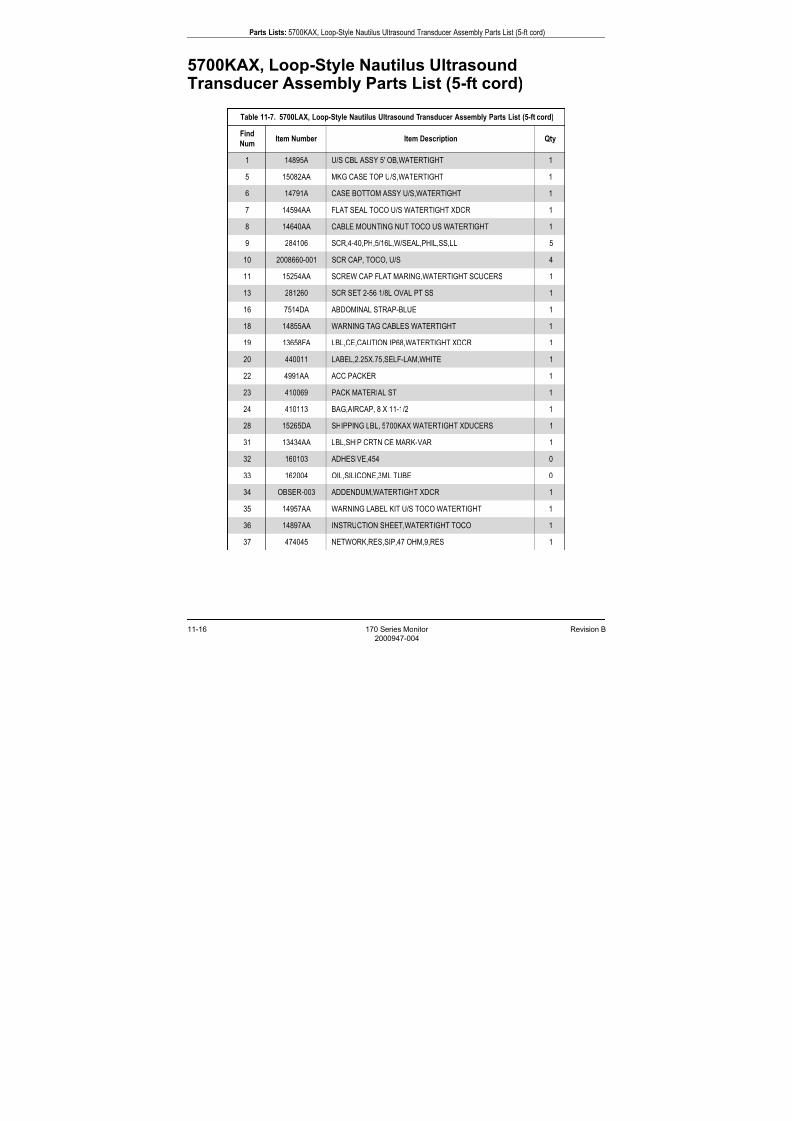
7/25/2019 Serv. Corometrics 170
http://slidepdf.com/reader/full/serv-corometrics-170 242/254
11-16 170 Series Monitor Revision B
2000947-004
Parts Lists: 5700KAX, Loop-Style Nautilus Ultrasound Transducer Assembly Parts List (5-ft cord)
5700KAX, Loop-Style Nautilus UltrasoundTransducer Assembly Parts List (5-ft cord)
Table 11-7. 5700LAX, Loop-Style Nautilus Ultrasound Transducer Assembly Parts List (5-ft cord)
Find
NumItem Number Item Description Qty
1 14895A U/S CBL ASSY 5' OB,WATERTIGHT 1
5 15082AA MKG CASE TOP U/S,WATERTIGHT 1
6 14791A CASE BOTTOM ASSY U/S,WATERTIGHT 1
7 14594AA FLAT SEAL TOCO U/S WATERTIGHT XDCR 1
8 14640AA CABLE MOUNTING NUT TOCO US WATERTIGHT 1
9 284106 SCR,4-40,PH,5/16L,W/SEAL,PHIL,SS,LL 5
10 2008660-001 SCR CAP, TOCO, U/S 4
11 15254AA SCREW CAP FLAT MARING,WATERTIGHT SCUCERS 1
13 281260 SCR SET 2-56 1/8L OVAL PT SS 1
16 7514DA ABDOMINAL STRAP-BLUE 1
18 14855AA WARNING TAG CABLES WATERTIGHT 1
19 13658FA LBL,CE,CAUTION IP68,WATERTIGHT XDCR 1
20 440011 LABEL,2.25X.75,SELF-LAM,WHITE 1
22 4991AA ACC PACKER 123 410069 PACK MATERIAL ST 1
24 410113 BAG,AIRCAP, 8 X 11-1/2 1
28 15265DA SHIPPING LBL, 5700KAX WATERTIGHT XDUCERS 1
31 13434AA LBL,SHIP CRTN CE MARK-VAR 1
32 160103 ADHESIVE,454 0
33 162004 OIL,SILICONE,3ML TUBE 0
34 OBSER-003 ADDENDUM,WATERTIGHT XDCR 1
35 14957AA WARNING LABEL KIT U/S TOCO WATERTIGHT 1
36 14897AA INSTRUCTION SHEET,WATERTIGHT TOCO 1
37 474045 NETWORK,RES,SIP,47 OHM,9,RES 1
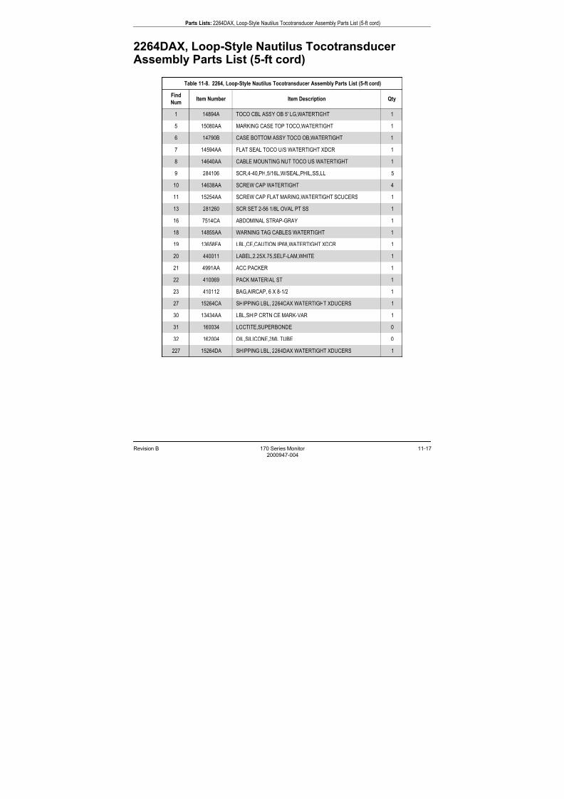
7/25/2019 Serv. Corometrics 170
http://slidepdf.com/reader/full/serv-corometrics-170 243/254
Revision B 170 Series Monitor 11-17
2000947-004
Parts Lists: 2264DAX, Loop-Style Nautilus Tocotransducer Assembly Parts List (5-ft cord)
2264DAX, Loop-Style Nautilus TocotransducerAssembly Parts List (5-ft cord)
Table 11-8. 2264, Loop-Style Nautilus Tocotransducer Assembly Parts List (5-ft cord)
Find
NumItem Number Item Description Qty
1 14894A TOCO CBL ASSY OB 5' LG,WATERTIGHT 1
5 15080AA MARKING CASE TOP TOCO,WATERTIGHT 1
6 14790B CASE BOTTOM ASSY TOCO OB,WATERTIGHT 1
7 14594AA FLAT SEAL TOCO U/S WATERTIGHT XDCR 1
8 14640AA CABLE MOUNTING NUT TOCO US WATERTIGHT 1
9 284106 SCR,4-40,PH,5/16L,W/SEAL,PHIL,SS,LL 5
10 14638AA SCREW CAP WATERTIGHT 4
11 15254AA SCREW CAP FLAT MARING,WATERTIGHT SCUCERS 1
13 281260 SCR SET 2-56 1/8L OVAL PT SS 1
16 7514CA ABDOMINAL STRAP-GRAY 1
18 14855AA WARNING TAG CABLES WATERTIGHT 1
19 13658FA LBL,CE,CAUTION IP68,WATERTIGHT XDCR 1
20 440011 LABEL,2.25X.75,SELF-LAM,WHITE 1
21 4991AA ACC PACKER 122 410069 PACK MATERIAL ST 1
23 410112 BAG,AIRCAP, 6 X 8-1/2 1
27 15264CA SHIPPING LBL, 2264CAX WATERTIGHT XDUCERS 1
30 13434AA LBL,SHIP CRTN CE MARK-VAR 1
31 160034 LOCTITE,SUPERBONDE 0
32 162004 OIL,SILICONE,3ML TUBE 0
227 15264DA SHIPPING LBL, 2264DAX WATERTIGHT XDUCERS 1

7/25/2019 Serv. Corometrics 170
http://slidepdf.com/reader/full/serv-corometrics-170 244/254
11-18 170 Series Monitor Revision B
2000947-004
Parts Lists: 1509AAO/BAO, Qwik Connect Plus Legplate Assembly Parts List
1509AAO/BAO, Qwik Connect Plus LegplateAssembly Parts List
Table 11-9. 1509AAO/BAO, Qwik Connect Plus Legplate Assembly Parts List
Find
NumItem Number Item Description Qty
1 2000532-001 CABLE STRAIN RELIEF 8 FEET 1
2 210227 CONTACT,MALE,24AWG,16.5MM,LG 11
3 210180 HALF-SHELL,W/CLAMP,3-5MM 1
4 210181 CLAMP,3-7MM 1
5 210176 RING 1
6 210183 GRIPPER,3-5MM 1
7 210182 SCREW,CLAMP,M 2.6 X 10 2
8 608048 SHRINK TUBING,1/4 BLK, .021
9 605105 WIRE,#24 STRANDED,GRN, .125
10 210179 HALF-SHELL,W/TONGUE 1
11 210178 RING,PLASTIC,21.8 X4 1
12 212133 PLUG,12 CKT GREY/BRN,A-D, 1
13 210226 CONTACT,MALE,24AWG,18MM L,G 1
14 2000528-001 COVER INTERFACE CABLE 115 2002641-001 O-RING .101 ID, .070THK, 70DUR, SILICONE 1
16 2000529-001 PIN COAX RECEPTACLE 1
17 2000527-001 CABLE BASE INTERFACE 1
18 2000429-003 PCB LEG PLATE BD 1
19 2000208-001 SPRING WIRE,LEG PLATE SNAP .125 STUD 1
20 440011 LABEL,2.25X.75,SELF-LAM,WHITE 1
22 2000595-001 LABEL SHIPPING FOR 1590AAO 1
23 410112 BAG,AIRCAP, 6 X 8-1/2 1
24 605106 WIRE,#24 STRANDED,BLUE .083
25 2002357-001 SPACER SPRING QWIK CONNECT PLUS 1
26 13658AA LABEL,CE MARK-ACCESSORIES,WATERPROOF 1

7/25/2019 Serv. Corometrics 170
http://slidepdf.com/reader/full/serv-corometrics-170 245/254
Revision B 170 Series Monitor
2000947-004

7/25/2019 Serv. Corometrics 170
http://slidepdf.com/reader/full/serv-corometrics-170 246/254
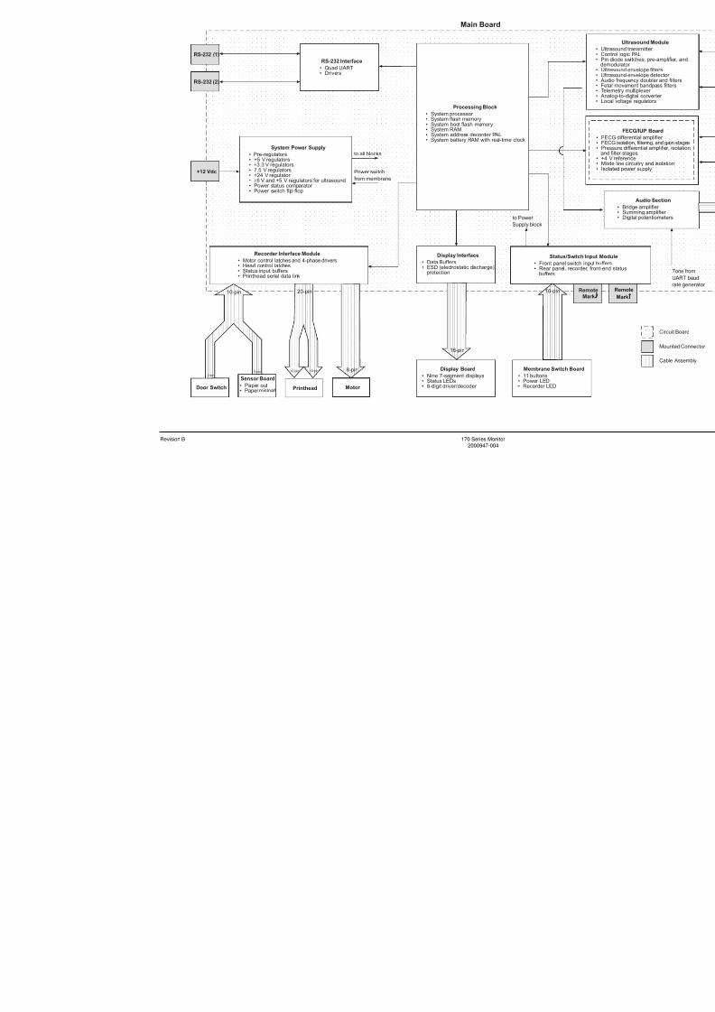
7/25/2019 Serv. Corometrics 170
http://slidepdf.com/reader/full/serv-corometrics-170 247/254
Revision B 170 Series Monitor
2000947-004

7/25/2019 Serv. Corometrics 170
http://slidepdf.com/reader/full/serv-corometrics-170 248/254
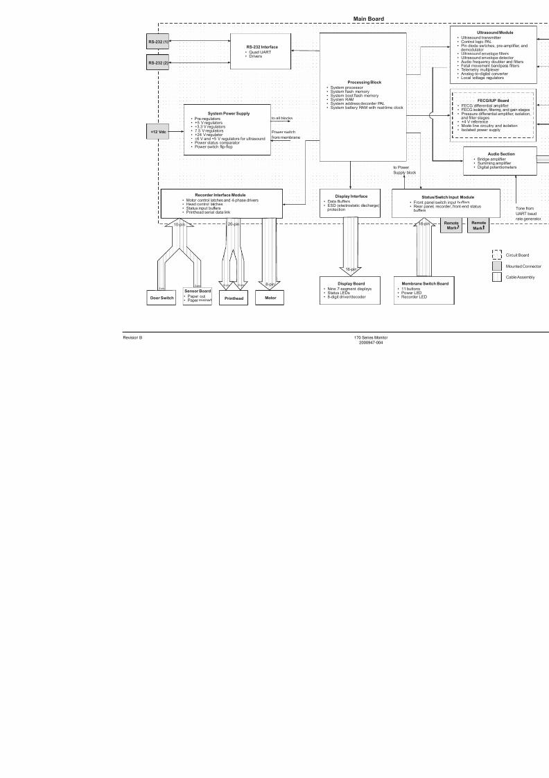
7/25/2019 Serv. Corometrics 170
http://slidepdf.com/reader/full/serv-corometrics-170 249/254
Revision B 170 Series Monitor
2000947-004

7/25/2019 Serv. Corometrics 170
http://slidepdf.com/reader/full/serv-corometrics-170 250/254
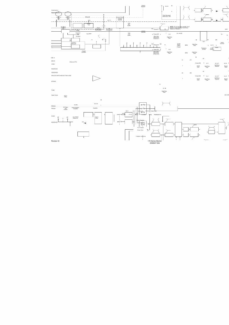
7/25/2019 Serv. Corometrics 170
http://slidepdf.com/reader/full/serv-corometrics-170 251/254
Revision B 170 Series Monitor
2000947-004

7/25/2019 Serv. Corometrics 170
http://slidepdf.com/reader/full/serv-corometrics-170 252/254

7/25/2019 Serv. Corometrics 170
http://slidepdf.com/reader/full/serv-corometrics-170 253/254
7/25/2019 Serv. Corometrics 170
http://slidepdf.com/reader/full/serv-corometrics-170 254/254