series 8060 6-meter earth station antenna site preparation ... · 6-meter earth station antenna...
TRANSCRIPT
Series 8060 6-Meter Earth Station
Antenna Site Preparation 120° and 180° Mounts
Installation and Operation Guide
Manual Part No. 42S042G April 2003

Notice
All Rights Reserved
The information contained in this document is proprietary to ViaSat, Inc. This document may not be reproduced or distributed in any form without the consent of ViaSat, Inc. The information in this document is subject to change without notice. ViaSat, Inc. assumes no responsibility for any errors that may appear in this document and does not warranty any specific application. Any product names mentioned herein are used for identification purposes only, and may be trademarks and/or registered trademarks of their respective companies. In all correspondence with ViaSat, Inc. regarding this publication, please refer to the Manual Part No. on the title page. Copyright ® 1998 - 2003 ViaSat, Inc. All rights reserved. No part of this book may be reproduced in any form or by any means without permission in writing from ViaSat, Inc.
Series 8060 6-Meter E
arth Station Antenna Site Preparation
120° and 180° Mounts
Installation and Operation G
uide
____________________________________________________________________________________________
TABLE OF CONTENTS
NOTE For a further or more detailed breakdown of section contents, refer to the title page of each section.
SECTION 1 GENERAL INFORMATION
1-1 Introduction to Manual
SECTION 2 ANTENNA SITE SELECTION (120° AND 180° ANTENNA) General 2-1
2-1 2-8
2-13 2-13 2-13
Determining Aiming Coordinates Verifying Operational Clearance Verifying Clear Line-of-Site Verifying Absence of Signal Interference Verifying Availability of Power Requirements
SECTION 3 FOUNDATION INSTALLATION (120° MOUNT)
3-1 3-1 3-1 3-5
General Antenna Considerations Foundation Design Considerations Foundation Construction
SECTION 4 FOUNDATION INSTALLATION (180° MOUNT)
4-1 4-1 4-1
4-18
General Antenna Considerations Foundation Design Considerations Foundation Construction
____________________________________________________________________________________________ 42S042F SERIES 8060 6-METER EARTH STATION ANTENNA ii

SECTION 1 GENERAL INFORMATION 1-1 Introduction to Manual
42S042F SERIES 8060 6-METER EARTH STATION ANTENNA
____________________________________________________________________________________________
____________________________________________________________________________________________ 42S042D SERIES 8060 6-METER EARTH STATION ANTENNA 1-1
SECTION 1 GENERAL INFORMATION
INTRODUCTION TO MANUAL
This manual contains information needed to properly locate and install the foundation for the 6-meter (6M) earth station antenna (120° and 180° travel).. Section 1 provides general information, Section 2 provides antenna site selection criteria for the 120° and 180°antenna, Section 3 provides the foundation installation information for the 120° mount, and Section 4 provides the foundation installation information for the 180° mount. All warnings and cautions should be reviewed before any procedures are performed. Failure to do so may result in personal injury or equipment damage. ViaSat, Inc. makes every effort to ensure that the information contained herein is correct and complete.
SECTION 2 ANTENNA SITE SELECTION (120° AND 180° ANTENNA)
2-1 General 2-1 Determining Aiming Coordinates 2-8 Verifying Operational Clearance 2-13 Verifying Clear Line-of-Sight 2-13 Verifying Absence of Signal Interference 2-13 Verifying Availability of Power Requirements 2-15 • Conduit Placement
42S042F SERIES 8060 6-METER EARTH STATION ANTENNA
____________________________________________________________________________________________
____________________________________________________________________________________________ 42S042D SERIES 8060 6-METER EARTH STATION ANTENNA 2-1
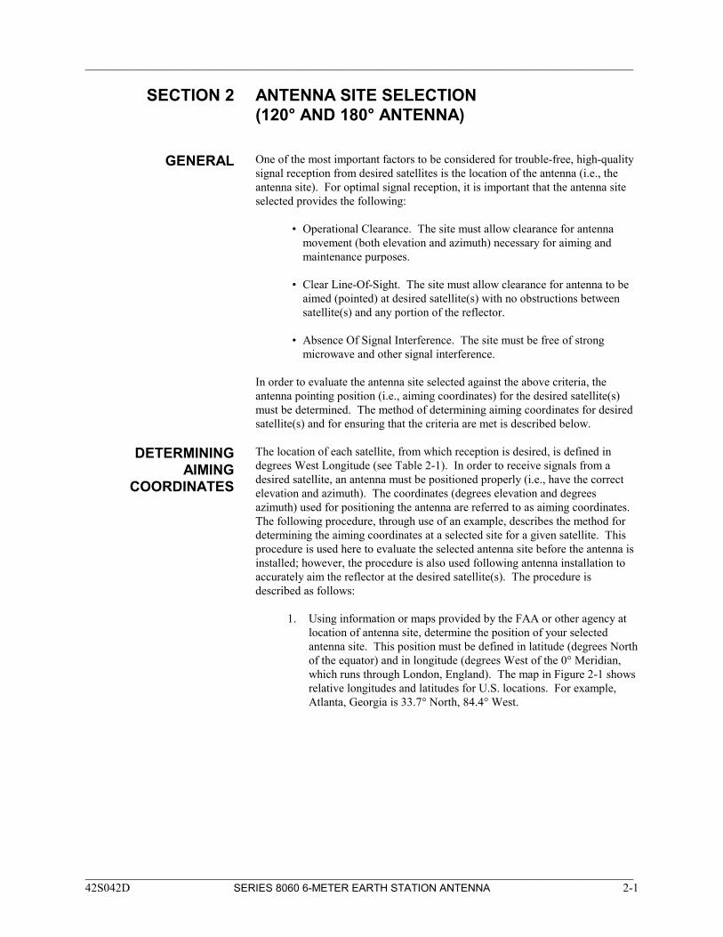
SECTION 2 ANTENNA SITE SELECTION (120° AND 180° ANTENNA)
GENERAL One of the most important factors to be considered for trouble-free, high-quality signal reception from desired satellites is the location of the antenna (i.e., the antenna site). For optimal signal reception, it is important that the antenna site selected provides the following: • Operational Clearance. The site must allow clearance for antenna
movement (both elevation and azimuth) necessary for aiming and maintenance purposes.
• Clear Line-Of-Sight. The site must allow clearance for antenna to be
aimed (pointed) at desired satellite(s) with no obstructions between satellite(s) and any portion of the reflector.
• Absence Of Signal Interference. The site must be free of strong
microwave and other signal interference. In order to evaluate the antenna site selected against the above criteria, the antenna pointing position (i.e., aiming coordinates) for the desired satellite(s) must be determined. The method of determining aiming coordinates for desired satellite(s) and for ensuring that the criteria are met is described below.
DETERMINING AIMING
COORDINATES
The location of each satellite, from which reception is desired, is defined in degrees West Longitude (see Table 2-1). In order to receive signals from a desired satellite, an antenna must be positioned properly (i.e., have the correct elevation and azimuth). The coordinates (degrees elevation and degrees azimuth) used for positioning the antenna are referred to as aiming coordinates. The following procedure, through use of an example, describes the method for determining the aiming coordinates at a selected site for a given satellite. This procedure is used here to evaluate the selected antenna site before the antenna is installed; however, the procedure is also used following antenna installation to accurately aim the reflector at the desired satellite(s). The procedure is described as follows: 1. Using information or maps provided by the FAA or other agency at
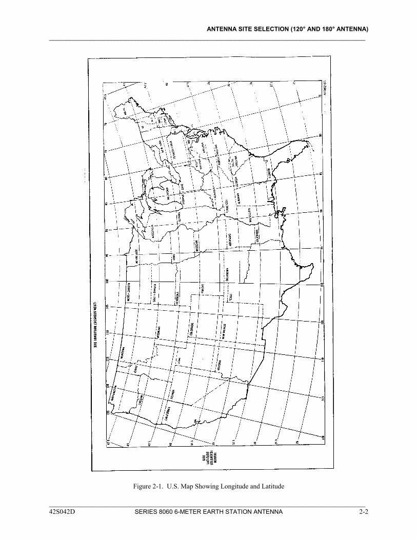
location of antenna site, determine the position of your selected antenna site. This position must be defined in latitude (degrees North of the equator) and in longitude (degrees West of the 0° Meridian, which runs through London, England). The map in Figure 2-1 shows relative longitudes and latitudes for U.S. locations. For example, Atlanta, Georgia is 33.7° North, 84.4° West.
ANTENNA SITE SELECTION (120° AND 180° ANTENNA) ____________________________________________________________________________________________
Figure 2-1. U.S. Map Showing Longitude and Latitude
____________________________________________________________________________________________ 42S042D SERIES 8060 6-METER EARTH STATION ANTENNA 2-2
ANTENNA SITE SELECTION (120° AND 180° ANTENNA) ____________________________________________________________________________________________
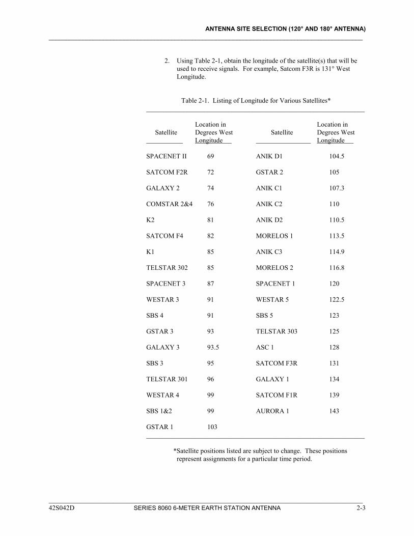
2. Using Table 2-1, obtain the longitude of the satellite(s) that will be
used to receive signals. For example, Satcom F3R is 131° West Longitude.
Table 2-1. Listing of Longitude for Various Satellites* ________________________________________________________________
Location in Location in Satellite Degrees West Satellite Degrees West Longitude Longitude SPACENET II 69 ANIK D1 104.5 SATCOM F2R 72 GSTAR 2 105 GALAXY 2 74 ANIK C1 107.3 COMSTAR 2&4 76 ANIK C2 110 K2 81 ANIK D2 110.5 SATCOM F4 82 MORELOS 1 113.5 K1 85 ANIK C3 114.9 TELSTAR 302 85 MORELOS 2 116.8 SPACENET 3 87 SPACENET 1 120 WESTAR 3 91 WESTAR 5 122.5 SBS 4 91 SBS 5 123 GSTAR 3 93 TELSTAR 303 125 GALAXY 3 93.5 ASC 1 128 SBS 3 95 SATCOM F3R 131 TELSTAR 301 96 GALAXY 1 134 WESTAR 4 99 SATCOM F1R 139 SBS 1&2 99 AURORA 1 143 GSTAR 1 103 ________________________________________________________________ *Satellite positions listed are subject to change. These positions
represent assignments for a particular time period.
____________________________________________________________________________________________ 42S042D SERIES 8060 6-METER EARTH STATION ANTENNA 2-3
ANTENNA SITE SELECTION (120° AND 180° ANTENNA) ____________________________________________________________________________________________
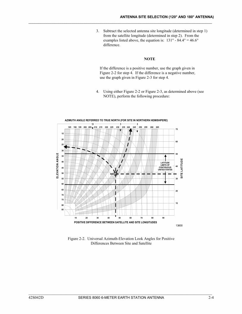
3. Subtract the selected antenna site longitude (determined in step 1) from the satellite longitude (determined in step 2). From the examples listed above, the equation is: 131° - 84.4° = 46.6° difference.
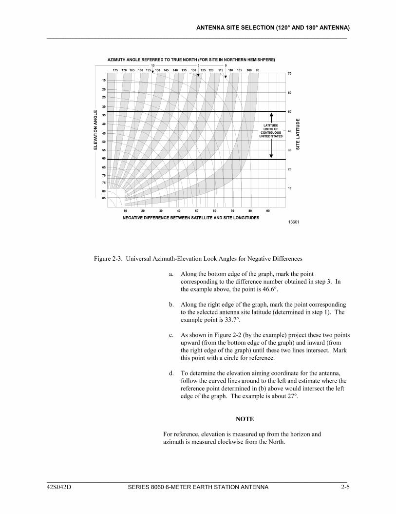
NOTE If the difference is a positive number, use the graph given in Figure 2-2 for step 4. If the difference is a negative number, use the graph given in Figure 2-3 for step 4.
4. Using either Figure 2-2 or Figure 2-3, as determined above (see
NOTE), perform the following procedure:
85
185 190 195 200 205 210 215 220 225 230 235 240 245 250 255 260 265
80
75
10
10
20
20
POSITIVE DIFFERENCE BETWEEN SATELLITE AND SITE LONGITUDES13600
SITE
LAT
ITU
DE
ELEV
ATIO
N A
NG
LE
AZIMUTH ANGLE REFERRED TO TRUE NORTH (FOR SITE IN NORTHERN HEMISHPERE)
30
30
40
40
50
50
60
60
70
70
80 90
70
65
60
55
50
45
40
35
25
30
20
15
10 5 0
LATITUDELIMITS OF
CONTIGUOUSUNITED STATES
Figure 2-2. Universal Azimuth-Elevation Look Angles for Positive Differences Between Site and Satellite
____________________________________________________________________________________________ 42S042D SERIES 8060 6-METER EARTH STATION ANTENNA 2-4
ANTENNA SITE SELECTION (120° AND 180° ANTENNA) ____________________________________________________________________________________________
85
175 170 165 160 155 150 145 140 135 130 125 120 115 110 105 100 95
80
75
10
10
20
20
NEGATIVE DIFFERENCE BETWEEN SATELLITE AND SITE LONGITUDES13601
SITE
LAT
ITU
DE
ELEV
ATIO
N A
NG
LE
AZIMUTH ANGLE REFERRED TO TRUE NORTH (FOR SITE IN NORTHERN HEMISHPERE)
30
30
40
40
50
50
60
60
70
70
80 90
70
65
60
55
50
45
40
35
25
30
20
15
10 5 0
LATITUDELIMITS OF
CONTIGUOUSUNITED STATES
Figure 2-3. Universal Azimuth-Elevation Look Angles for Negative Differences a. Along the bottom edge of the graph, mark the point
corresponding to the difference number obtained in step 3. In the example above, the point is 46.6°.
b. Along the right edge of the graph, mark the point corresponding
to the selected antenna site latitude (determined in step 1). The example point is 33.7°.
c. As shown in Figure 2-2 (by the example) project these two points
upward (from the bottom edge of the graph) and inward (from the right edge of the graph) until these two lines intersect. Mark this point with a circle for reference.
d. To determine the elevation aiming coordinate for the antenna,
follow the curved lines around to the left and estimate where the reference point determined in (b) above would intersect the left edge of the graph. The example is about 27°.
NOTE For reference, elevation is measured up from the horizon and azimuth is measured clockwise from the North.
____________________________________________________________________________________________ 42S042D SERIES 8060 6-METER EARTH STATION ANTENNA 2-5
ANTENNA SITE SELECTION (120° AND 180° ANTENNA) ____________________________________________________________________________________________
e. To determine the azimuth aiming coordinate for the antenna, follow the curved lines upward and estimate where the reference point determined in (b) above would intersect the upper edge of the graph. The example is about 242°.
5. When using a compass to locate the azimuth aiming coordinate
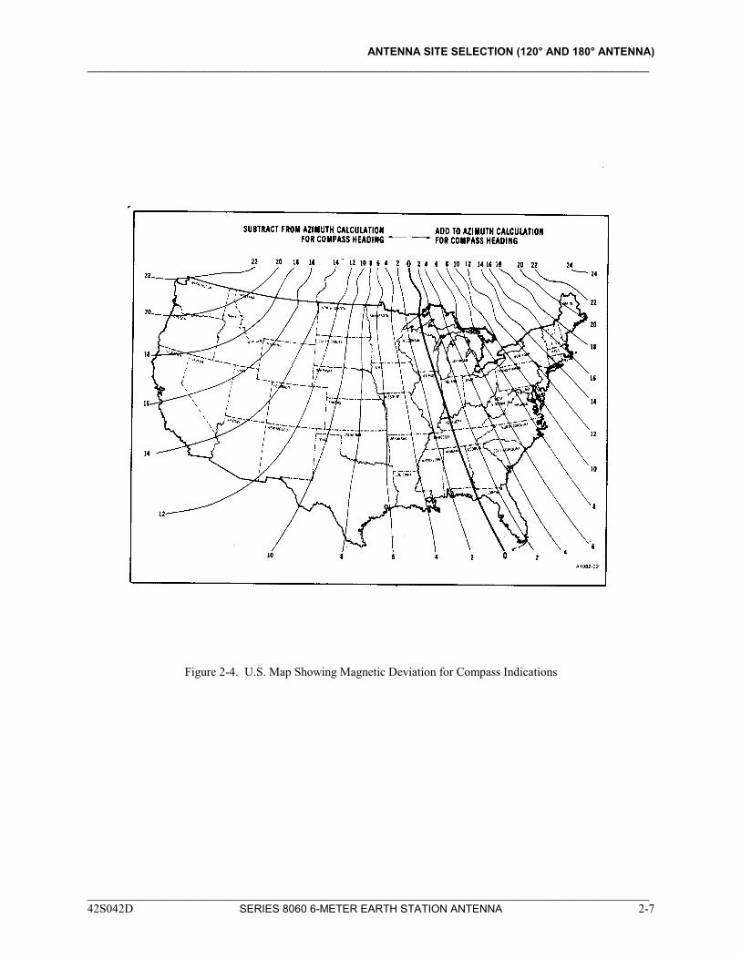
determined in step 4.e above, it may be necessary to adjust the compass indication (because of magnetic deviation) before pointing the antenna. In the example, the azimuth angle is 242°; however, from Figure 2-4, Atlanta, Georgia, is about +1° of magnetic deviation from true North. Therefore, to compensate for deviation, add 1° to our azimuth calculation: 242° + 1° = 243°, which is the actual compass reading to use in pointing the antenna.
NOTE
The above method should be used in determining the antenna aiming coordinates for both the satellite(s) from which reception is currently desired and for satellite(s) from which reception may be desired in the future.
Azimuth and elevation aiming coordinates may also be determined by
formula using a digital calculator. In these formulas, X represents the site latitude in degrees, Y represents the site longitude in degrees, and Z represents the satellite longitude in degrees. For the southern hemisphere, enter X as negative. If west longitudes are entered as positive numbers, define the longitude difference as:
D = Z - Y If East longitudes are entered as positive numbers, define the
longitude difference as: D = Y - Z The constant K is defined as:
K = 1
6.611
Compute the elevation angle E and the azimuth angle A according to
the following formulas:
( ) ( )
E D x X K
D D x X=
−
−
+tan
cos cos
sin cos sin
12 2
A = tan-1 tan Dsin X
If X>0 (i.e., a northern hemisphere latitude), then add 180° to A to
get the angle from true north. Then add the appropriate magnetic deviation angle as described before to obtain the compass heading.
____________________________________________________________________________________________ 42S042D SERIES 8060 6-METER EARTH STATION ANTENNA 2-6
ANTENNA SITE SELECTION (120° AND 180° ANTENNA) ____________________________________________________________________________________________
Figure 2-4. U.S. Map Showing Magnetic Deviation for Compass Indications
____________________________________________________________________________________________ 42S042D SERIES 8060 6-METER EARTH STATION ANTENNA 2-7
ANTENNA SITE SELECTION (120° AND 180° ANTENNA) ____________________________________________________________________________________________
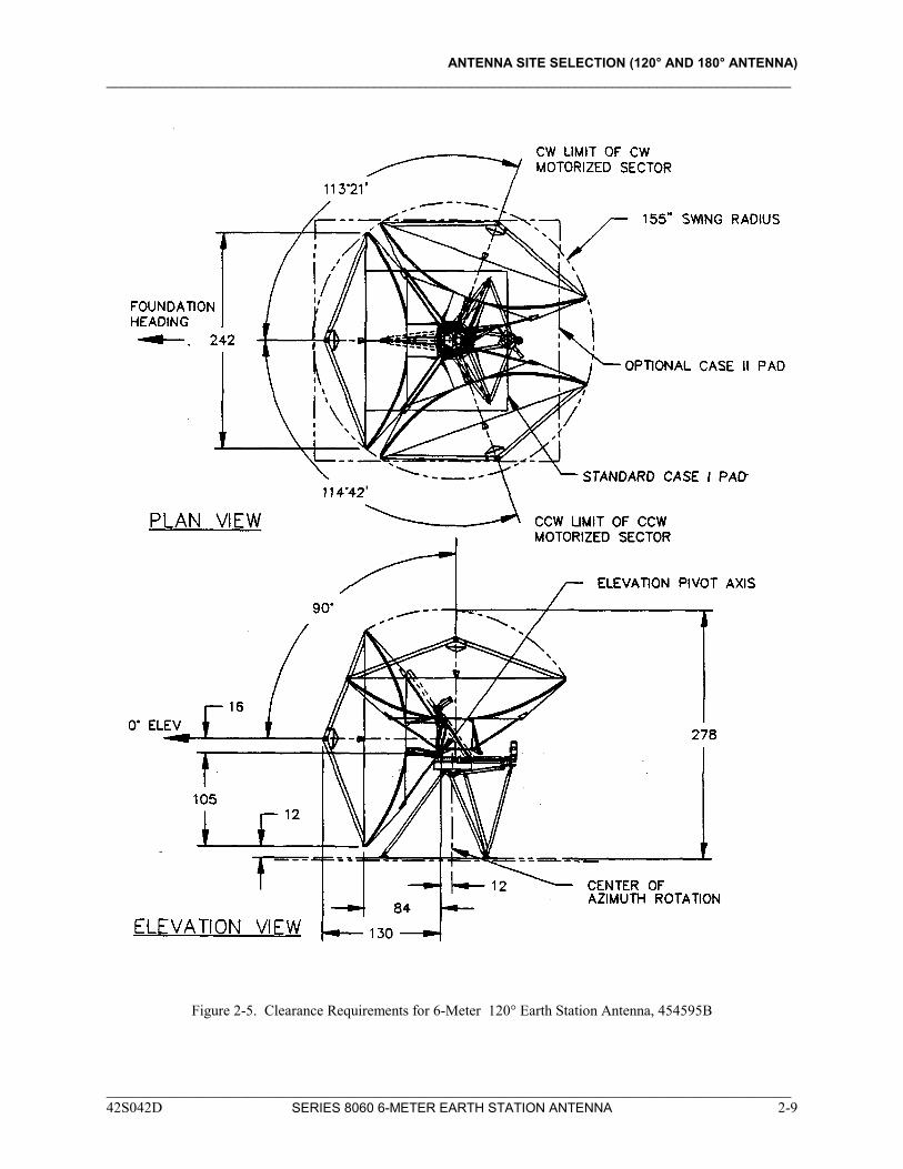
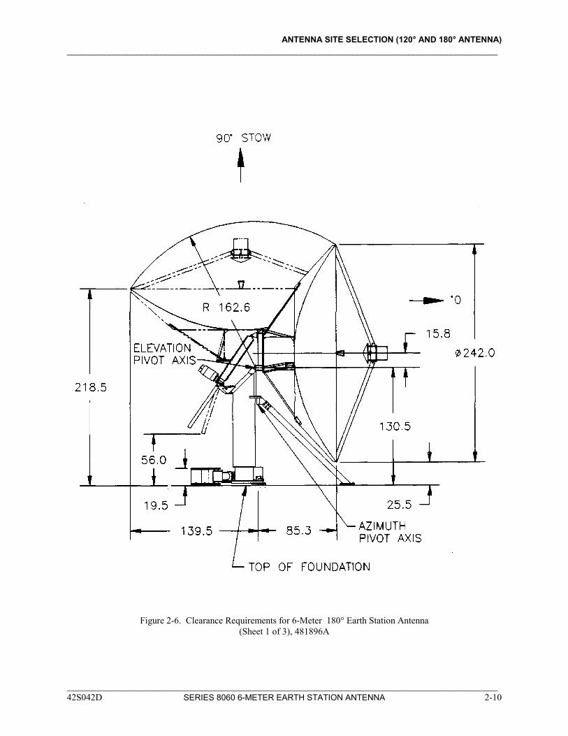
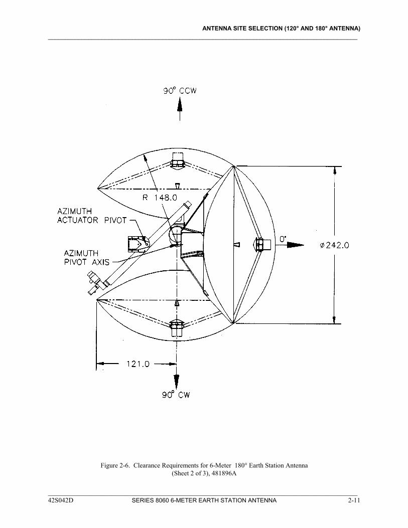
Once the antenna aiming coordinates have been determined, it is necessary to verify operational clearance (see Figure 2-5 for 120° and Figure 2-6 for 180° antenna). This ensures that the antenna movement necessary for both aiming and maintenance purposes is not restricted.
VERIFYING OPERATIONAL
CLEARANCE
CAUTION
__________________________________________ No buildings, walls, fences, or other permanent fixtures should be planned for installation any closer than 2 meters from the antenna and foundation envelope without consultation with the factory. __________________________________________
NOTE The rotational limits identified in Figure 2-5 specify clearance requirements for all possible azimuth pointing angles for the 120° antenna. The motorized azimuth pointing angle range is three 120° continuous sectors. These three sectors are:
Left Sector: 114° 42' left to 5° 18' right
Center Sector: 60° left to 60° right
Right Sector: 6° 38' left to 113° 22' right The rotational limits identified in Figure 2-6 specify clearance requirements for all possible azimuth pointing angles for the 180° antenna. The motorized azimuth pointing angle range is three 180° continuous sectors. These three sectors are:
Center Sector: 90° left to 90° right The manual azimuth pointing range is 360°.
NOTE No buildings, walls, fences, or other permanent fixtures should be planned for installation any closer than 2 meters of the antenna and foundation envelope without consultation with the factory.
____________________________________________________________________________________________ 42S042D SERIES 8060 6-METER EARTH STATION ANTENNA 2-8
ANTENNA SITE SELECTION (120° AND 180° ANTENNA) ____________________________________________________________________________________________
Figure 2-5. Clearance Requirements for 6-Meter 120° Earth Station Antenna, 454595B
____________________________________________________________________________________________ 42S042D SERIES 8060 6-METER EARTH STATION ANTENNA 2-9
ANTENNA SITE SELECTION (120° AND 180° ANTENNA) ____________________________________________________________________________________________
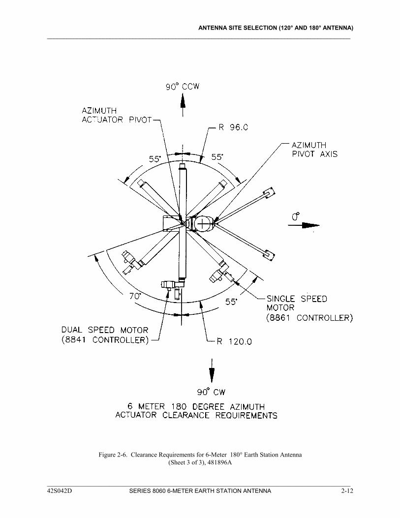
Figure 2-6. Clearance Requirements for 6-Meter 180° Earth Station Antenna (Sheet 1 of 3), 481896A
____________________________________________________________________________________________ 42S042D SERIES 8060 6-METER EARTH STATION ANTENNA 2-10
ANTENNA SITE SELECTION (120° AND 180° ANTENNA) ____________________________________________________________________________________________
Figure 2-6. Clearance Requirements for 6-Meter 180° Earth Station Antenna (Sheet 2 of 3), 481896A
____________________________________________________________________________________________ 42S042D SERIES 8060 6-METER EARTH STATION ANTENNA 2-11
ANTENNA SITE SELECTION (120° AND 180° ANTENNA) ____________________________________________________________________________________________
Figure 2-6. Clearance Requirements for 6-Meter 180° Earth Station Antenna (Sheet 3 of 3), 481896A
____________________________________________________________________________________________ 42S042D SERIES 8060 6-METER EARTH STATION ANTENNA 2-12
ANTENNA SITE SELECTION (120° AND 180° ANTENNA) ____________________________________________________________________________________________
____________________________________________________________________________________________ 42S042D SERIES 8060 6-METER EARTH STATION ANTENNA 2-13
VERIFYING CLEAR LINE-OF-SIGHT
Once the operational clearance has been verified, it is necessary to verify a clear line-of-sight. This ensures that the antenna may be aimed at desired satellite(s) without obstruction between the satellite(s) and any portion of the reflector. When using the satellite(s) aiming coordinates for a particular site, be sure that there are no trees, buildings, power lines, etc., between the dish location and the satellite. It is important that this clearance includes the total dish surface area and that nothing is blocking any portion of the dish surface.
VERIFYING ABSENCE OF
SIGNAL INTERFERENCE
For optimal signal reception, it is important that the antenna site selected be free of strong microwave or other signal interface. Microwave systems in the vicinity of a selected antenna site can cause interference. If a known source of interference (e.g., a Bell System microwave tower) is close by, it may be necessary to have a site survey performed to determine if the site selected is suitable. Two of the companies which perform these services are: Comsearch, Inc. Spectrum Planning, Inc. 11720 Sunrise Valley Drive P.O. Box 831360 Reston, VA 22091 Richardson, TX 75083 - 1360 (703) 620-6300 (214) 680-1000
VERIFYING AVAILABILITY OF
POWER REQUIREMENTS
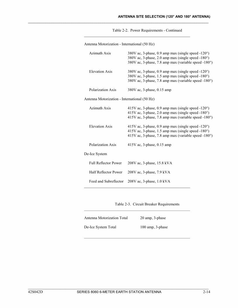
The power requirements will vary depending on the options purchased with the 6M antenna. Table 2-2 provides a list of the power requirements for each option. Table 2-3 provides a list of the circuit breaker requirements for each option. Verify that adequate power is available prior to finalizing the selection of the site.
Table 2-2. Power Requirements ______________________________________________________ Antenna Motorization - Domestic (60 Hz) Azimuth Axis 208V ac, 3-phase, 1.9 amp max (single speed -120°) 208V ac, 3-phase, 3.6 amp max (single speed -180°) 208V ac, 3-phase, 14.8 amp max (variable speed -180°) Elevation Axis 208V ac, 3-phase, 1.9 amp max (single speed -120°) 208V ac, 3-phase, 3.2 amp max (single speed -180°) 208V ac, 3-phase, 14.8 amp max (variable speed -180°) Polarization Axis 208V ac, 3-phase, 0.24 amp
ANTENNA SITE SELECTION (120° AND 180° ANTENNA) ____________________________________________________________________________________________
Table 2-2. Power Requirements - Continued ______________________________________________________ Antenna Motorization - International (50 Hz) Azimuth Axis 380V ac, 3-phase, 0.9 amp max (single speed -120°) 380V ac, 3-phase, 2.0 amp max (single speed -180°) 380V ac, 3-phase, 7.8 amp max (variable speed -180°) Elevation Axis 380V ac, 3-phase, 0.9 amp max (single speed -120°) 380V ac, 3-phase, 1.5 amp max (single speed -180°) 380V ac, 3-phase, 7.8 amp max (variable speed -180°) Polarization Axis 380V ac, 3-phase, 0.15 amp Antenna Motorization - International (50 Hz) Azimuth Axis 415V ac, 3-phase, 0.9 amp max (single speed -120°) 415V ac, 3-phase, 2.0 amp max (single speed -180°) 415V ac, 3-phase, 7.8 amp max (variable speed -180°) Elevation Axis 415V ac, 3-phase, 0.9 amp max (single speed -120°) 415V ac, 3-phase, 1.5 amp max (single speed -180°) 415V ac, 3-phase, 7.8 amp max (variable speed -180°) Polarization Axis 415V ac, 3-phase, 0.15 amp De-Ice System Full Reflector Power 208V ac, 3-phase, 15.8 kVA Half Reflector Power 208V ac, 3-phase, 7.9 kVA Feed and Subreflector 208V ac, 3-phase, 1.0 kVA ______________________________________________________
Table 2-3. Circuit Breaker Requirements ______________________________________________________ Antenna Motorization Total 20 amp, 3-phase De-Ice System Total 100 amp, 3-phase ______________________________________________________
____________________________________________________________________________________________ 42S042D SERIES 8060 6-METER EARTH STATION ANTENNA 2-14
ANTENNA SITE SELECTION (120° AND 180° ANTENNA) ____________________________________________________________________________________________
Conduit Placement Prior to installing the foundation (the next section), determination must be made
as to how power and control cables will be run to the antenna. If the cables are to be run underground, conduit must be placed in the foundation prior to pouring the cement. Refer to Figure 3-3 in the next section for the recommended location of conduit with the foundation for the 120° antenna. Refer to Figure 4-2 in Section 4 for the recommended location of conduit within the foundation for the 180° antenna.
____________________________________________________________________________________________ 42S042D SERIES 8060 6-METER EARTH STATION ANTENNA 2-15
SECTION 3 FOUNDATION INSTALLATION (120° MOUNT)
3-1 General 3-1 Antenna Considerations 3-1 Foundation Design Considerations 3-5 Foundation Construction
42S042F SERIES 8060 6-METER EARTH STATION ANTENNA
____________________________________________________________________________________________
____________________________________________________________________________________________ 42S042G SERIES 8060 6-METER EARTH STATION ANTENNA 3-1
SECTION 3 FOUNDATION INSTALLATION (120° MOUNT)
GENERAL The pointing accuracy of the installed antenna is determined by the stiffness of the mount, the reflector, and the foundation. Therefore, antenna foundation preparation is an essential part of antenna installation.
ANTENNA CONSIDERATIONS
The foundation heading is critical to the performance of the motorized antenna, but not to the performance of the non-motorized antenna. The foundation heading establishes the center of azimuth travel. For a non-motorized antenna to be later upgraded to motorization, the foundation heading must be installed initially as though for a motorized antenna. Proper electrical grounding shall be provided by the installing contractor to meet local applicable codes. Depending on local soil conditions, this may take the form of a buried grid or a suitable copper stake. The antenna mount shall be electrically connected to the ground. Provisions must be made to provide suitable support for power, RF, and control cables either by buried conduit or overhead raceway. If conduit is supplied, it shall be at least 3 inches (7.6 cm) in diameter. Lightning arrestors must be provided across all cables leaving the antenna per applicable local codes and N.F.P.A. codes. (Refer to Section 2 for information on required operational clearances.)
FOUNDATION DESIGN
CONSIDERATIONS
The antenna is designed to withstand an effective velocity pressure of 31 pounds per square (151.4 kg/m2) foot in any orientation, or 40 pounds per square foot (195.3 kg/m2) if stowed. These pressures represent 110 and 125 mile per hour (176 and 200 km/h) winds respectively at standard air at ground level. The foundation should be designed to maintain the antenna integrity under these same loads, with a safety factor of at least 1.5, and also to not allow the mounting plane of the three antenna feet to tilt more than 0.02°. The loading for the above conditions is presented in Tables 3-1 and 3-2. Figure 3-1 depicts the sign conventions for the tables. The loads for each mounting foot are listed in Table 3-1 and the resultant foundation loads are listed in Table 3-2. If loads are required for wind pressures other than those listed, they may be calculated from the information in the tables using the following procedure: 1. Subtract the corresponding Weight Only load components from the
load components for the orientation of interest.
FOUNDATION INSTALLATION (120° MOUNT) ____________________________________________________________________________________________
2. Divide the desired wind pressure by the wind pressure for the
orientation of interest. 3. Multiply each of the load components by the factor obtained in
step 2. 4. Add back the Weight Only components which were subtracted in
step 1. The following information presents a typical pad foundation design. If a special foundation design or load frame is required, a qualified structural engineer who is familiar with local structural codes should be employed. The foundation loading information below should be used in implementing the design.
FOOT 1
FOOT 3
+X
+Y
+Z(OUT OF PAPER)
FOOT 2
WINDDIRECTION
AZ ANGLE
0° AZ REF
WINDANGLE
Figure 3-1. Sign Conventions For Foundation Loading, 454573
NOTE
The following tables list forces which are the loads applied to the foundation by the antenna. Forces are in pounds; moments are in pound-feet.
____________________________________________________________________________________________ 3-2 SERIES 8060 6-METER EARTH STATION ANTENNA 42S042G
FOUNDATION INSTALLATION (120° MOUNT) ____________________________________________________________________________________________
Table 3-1. Loads at Individual Antenna Feet, 454573 _______________________________________________________________________________ AZ LOAD WIND EL ----------FOOT 1---------- ----------FOOT 2---------- ----------FOOT 3-------- ANGL CASE DIR ANGL Fx Fy Fz Fx Fy Fz Fx Fy Fz 0 Weight Only - 0 629 60 -558 -1259 -0 -1896 629 -60 -558 0 Weight Only - 60 448 375 -830 -894 -0 -1350 448 -375 -830 0 Weight Only - 90 324 589 -1016 -648 -0 -980 324 -589 -1016 0 31.0 PSF & Wt 0 0 2044 6168 -9296 10740 0 15581 2044 -6168 -9296 0 31.0 PSF & Wt 0 60 3617 4628 -8430 -138 -0 -287 3617 -4628 -8430 0 31.0 PSF & Wt 0 90 -519 3056 -3562 2785 0 4112 -519 -3056 -3562 0 31.0 PSF & Wt 60 0 780 6600 -8922 11519 -993 16716 3492 -6529 -10806 0 31.0 PSF & Wt 120 0 3069 -421 -1725 -2752 1652 -4071 -2162 977 2783 0 31.0 PSF & Wt 180 0 -389 -4337 5734 -9898 -0 -14479 -389 4337 5734 0 31.0 PSF & Wt 180 60 1278 -2894 2741 -5390 -0 -8001 1278 2894 2741 0 31.0 PSF & Wt 180 90 1168 -1878 1530 -4081 -0 -6073 1168 1878 1530 0 40.0 PSF & Wt 0 90 -765 3775 -4304 3786 0 5597 -765 -3775 -4304 0 40.0 PSF & Wt 180 90 1413 -2597 2272 -5081 -0 -7556 1413 2597 2272 30 Weight Only - 0 335 -18 -231 -1180 294 -1777 844 -276 -1003 30 Weight Only - 60 332 344 -703 -863 115 -1303 532 -459 -1004 30 Weight Only - 90 331 591 -1025 -650 -7 -984 318 -583 -1003 30 31.0 PSF & Wt 0 0 4600 9495 -15368 9210 -744 13359 -969 -1336 -1003 30 31.0 PSF & Wt 0 60 4008 5999 -10418 -644 476 -1014 2782 -2925 -5715 30 31.0 PSF & Wt 0 90 822 3728 -5435 2327 -1129 3427 -1637 -1726 -1004 30 31.0 PSF & Wt 60 0 3614 10407 -15805 10255 -1819 14886 267 -1493 -2092 30 31.0 PSF & Wt 120 0 2194 -1546 350 -3359 2112 -4961 -1537 423 1599 30 31.0 PSF & Wt 180 0 -2736 -6867 10666 -8658 1041 -12673 2149 487 -1004 30 31.0 PSF & Wt 180 60 -525 -3882 5363 -4745 1456 -7042 2815 1009 -839 30 31.0 PSF & Wt 180 90 -160 -2546 3385 -3625 1115 -5392 2275 558 -1004 30 40.0 PSF & Wt 0 90 965 4642 -6721 3196 -1455 4713 -2207 -2059 -1004 30 40.0 PSF & Wt 180 90 -303 -3460 4670 -4493 1442 -6678 2845 891 -1004 60 Weight Only - 0 37 64 -111 -957 510 -1450 920 -574 -1451 60 Weight Only - 60 217 376 -658 -777 199 -1176 561 -574 -1177 60 Weight Only - 90 339 586 -1026 -657 -12 -993 317 -575 -992 60 31.0 PSF & Wt 0 0 6022 10430 -17588 5019 -1292 7287 -3629 3703 7290 60 31.0 PSF & Wt 0 60 3853 6674 -11144 -2030 820 -3003 1724 -1347 -3001 60 31.0 PSF & Wt 0 90 2046 3544 -6120 1045 -1958 1554 -2218 -74 1554 60 31.0 PSF & Wt 60 0 5322 11732 -18724 6055 -2469 8799 -2683 3950 6913 60 31.0 PSF & Wt 120 0 1267 -2366 2063 -3247 2546 -4792 -855 -674 -284 60 31.0 PSF & Wt 180 0 -4272 -7399 12471 -5261 1807 -7742 4195 -3652 -7741 60 31.0 PSF & Wt 180 60 -2131 -3690 6323 -2948 2526 -4420 3662 -1291 -4421 60 31.0 PSF & Wt 180 90 -1367 -2369 4064 -2358 1932 -3538 2852 -1075 -3537 60 40.0 PSF & Wt 0 90 2544 4406 -7605 1541 -2524 2297 -2957 73 2297 60 40.0 PSF & Wt 180 90 -1865 -3230 5548 -2854 2499 -4281 3591 -1221 -4279 _______________________________________________________________________________
____________________________________________________________________________________________ 42S042G SERIES 8060 6-METER EARTH STATION ANTENNA 3-3
FOUNDATION INSTALLATION (120° MOUNT) ____________________________________________________________________________________________
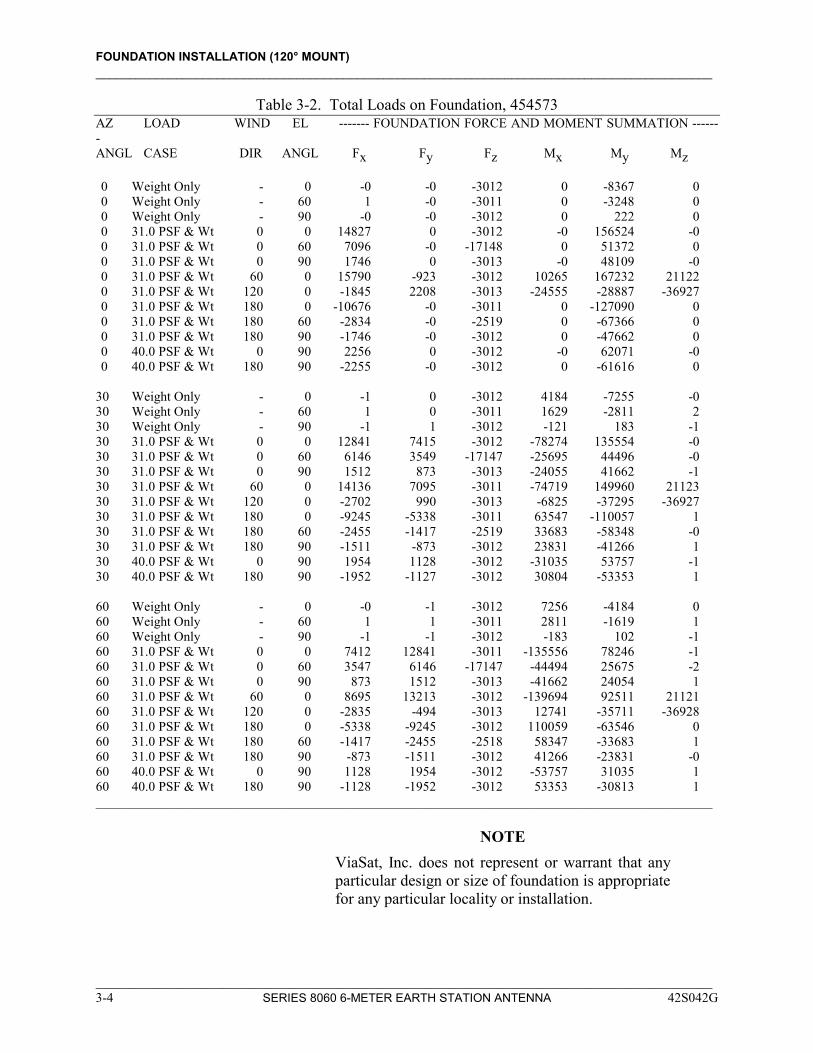
Table 3-2. Total Loads on Foundation, 454573 AZ LOAD WIND EL ------- FOUNDATION FORCE AND MOMENT SUMMATION ------- ANGL CASE DIR ANGL Fx Fy Fz Mx My Mz 0 Weight Only - 0 -0 -0 -3012 0 -8367 0 0 Weight Only - 60 1 -0 -3011 0 -3248 0 0 Weight Only - 90 -0 -0 -3012 0 222 0 0 31.0 PSF & Wt 0 0 14827 0 -3012 -0 156524 -0 0 31.0 PSF & Wt 0 60 7096 -0 -17148 0 51372 0 0 31.0 PSF & Wt 0 90 1746 0 -3013 -0 48109 -0 0 31.0 PSF & Wt 60 0 15790 -923 -3012 10265 167232 21122 0 31.0 PSF & Wt 120 0 -1845 2208 -3013 -24555 -28887 -36927 0 31.0 PSF & Wt 180 0 -10676 -0 -3011 0 -127090 0 0 31.0 PSF & Wt 180 60 -2834 -0 -2519 0 -67366 0 0 31.0 PSF & Wt 180 90 -1746 -0 -3012 0 -47662 0 0 40.0 PSF & Wt 0 90 2256 0 -3012 -0 62071 -0 0 40.0 PSF & Wt 180 90 -2255 -0 -3012 0 -61616 0 30 Weight Only - 0 -1 0 -3012 4184 -7255 -0 30 Weight Only - 60 1 0 -3011 1629 -2811 2 30 Weight Only - 90 -1 1 -3012 -121 183 -1 30 31.0 PSF & Wt 0 0 12841 7415 -3012 -78274 135554 -0 30 31.0 PSF & Wt 0 60 6146 3549 -17147 -25695 44496 -0 30 31.0 PSF & Wt 0 90 1512 873 -3013 -24055 41662 -1 30 31.0 PSF & Wt 60 0 14136 7095 -3011 -74719 149960 21123 30 31.0 PSF & Wt 120 0 -2702 990 -3013 -6825 -37295 -36927 30 31.0 PSF & Wt 180 0 -9245 -5338 -3011 63547 -110057 1 30 31.0 PSF & Wt 180 60 -2455 -1417 -2519 33683 -58348 -0 30 31.0 PSF & Wt 180 90 -1511 -873 -3012 23831 -41266 1 30 40.0 PSF & Wt 0 90 1954 1128 -3012 -31035 53757 -1 30 40.0 PSF & Wt 180 90 -1952 -1127 -3012 30804 -53353 1 60 Weight Only - 0 -0 -1 -3012 7256 -4184 0 60 Weight Only - 60 1 1 -3011 2811 -1619 1 60 Weight Only - 90 -1 -1 -3012 -183 102 -1 60 31.0 PSF & Wt 0 0 7412 12841 -3011 -135556 78246 -1 60 31.0 PSF & Wt 0 60 3547 6146 -17147 -44494 25675 -2 60 31.0 PSF & Wt 0 90 873 1512 -3013 -41662 24054 1 60 31.0 PSF & Wt 60 0 8695 13213 -3012 -139694 92511 21121 60 31.0 PSF & Wt 120 0 -2835 -494 -3013 12741 -35711 -36928 60 31.0 PSF & Wt 180 0 -5338 -9245 -3012 110059 -63546 0 60 31.0 PSF & Wt 180 60 -1417 -2455 -2518 58347 -33683 1 60 31.0 PSF & Wt 180 90 -873 -1511 -3012 41266 -23831 -0 60 40.0 PSF & Wt 0 90 1128 1954 -3012 -53757 31035 1 60 40.0 PSF & Wt 180 90 -1128 -1952 -3012 53353 -30813 1 ____________________________________________________________________________________________
NOTE
ViaSat, Inc. does not represent or warrant that any particular design or size of foundation is appropriate for any particular locality or installation.
____________________________________________________________________________________________ 3-4 SERIES 8060 6-METER EARTH STATION ANTENNA 42S042G
FOUNDATION INSTALLATION (120° MOUNT) ____________________________________________________________________________________________
____________________________________________________________________________________________ 42S042G SERIES 8060 6-METER EARTH STATION ANTENNA 3-5
FOUNDATION CONSTRUCTION
Refer to Table 3-3 for the recommended foundation size. Figure 3-2 and the following information provide the installation information. These recommendations are based on the soil conditions listed and do not consider any special clearance requirements. 1. The minimum safe soil-bearing capacity is 2000 PSF (96 kN/m2). 2. Reinforcing bars shall conform to ASTM A615, grade 60. 3. Do not weld anchor bolts to reinforcing bars. This will remove the
temper and reduce the strength of the anchor bolts. 4. All concrete shall be building code standard weight 3000 psi (20,700
kN/m2) compressive strength at 28 days. 5. Areas (6 X 12 inch or 15.2 cm X 30.4 cm) for mounting feet should
be flat within 1/16 inch and level with respect to one another within 1/4 inch (6 mm).
6. Anchor bolts are 1 inch diameter and must conform to ASTM A193
grade B7 or ASTM A325. 7. Do not use nuts under the foot, 454063. The foot must rest flush on
the concrete pad. Use one washer, 85844, and one flourocarbon-coated nut, 337880, per anchor bolt to secure foot to pad. After the concrete is fully cured, torque the nuts to 245-270 foot-pounds (333-367 Nm).
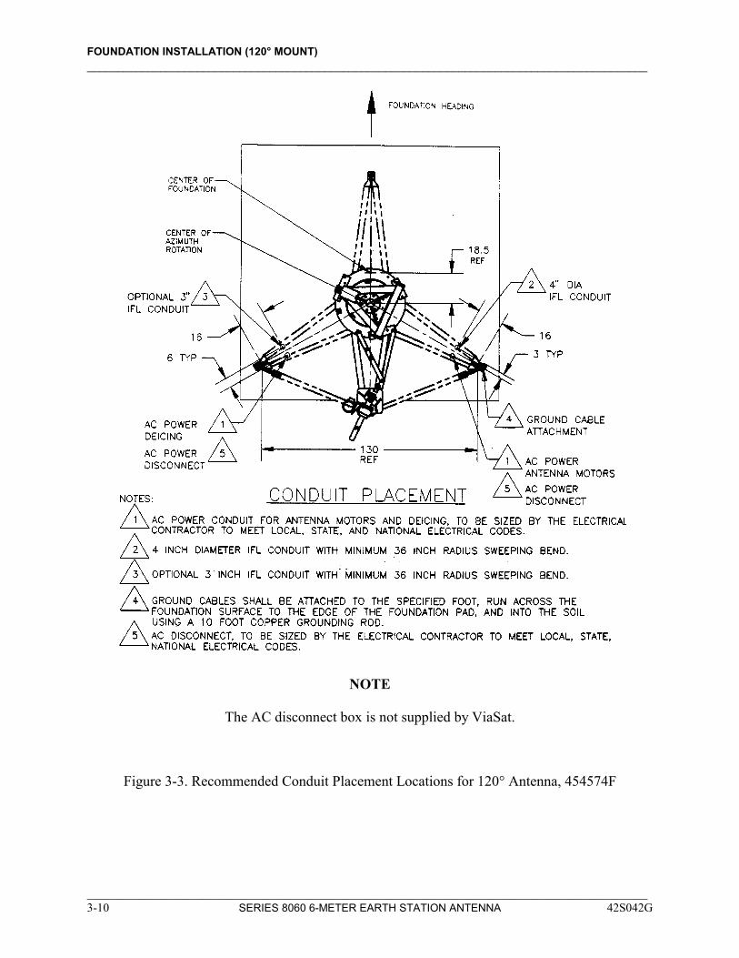
Refer to Figure 3-3 for 6-meter 120° conduit placement.

FOUNDATION INSTALLATION (120° MOUNT) ____________________________________________________________________________________________
Figure 3-2. Antenna Foundation Installation (Sheet 1 of 4), 454574F
____________________________________________________________________________________________ 3-6 SERIES 8060 6-METER EARTH STATION ANTENNA 42S042G
FOUNDATION INSTALLATION (120° MOUNT) ____________________________________________________________________________________________
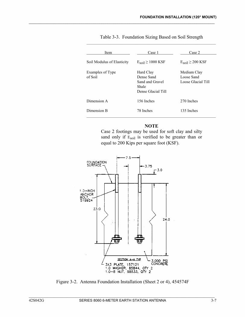
Table 3-3. Foundation Sizing Based on Soil Strength
________________________________________________________________ Item Case 1 Case 2 Soil Modulus of Elasticity Esoil ≥ 1000 KSF Esoil ≥ 200 KSF
Examples of Type Hard Clay Medium Clay of Soil Dense Sand Loose Sand Sand and Gravel Loose Glacial Till Shale Dense Glacial Till
Dimension A 156 Inches 270 Inches
Dimension B 78 Inches 135 Inches ________________________________________________________________
NOTE Case 2 footings may be used for soft clay and silty sand only if Esoil is verified to be greater than or equal to 200 Kips per square foot (KSF).
Figure 3-2. Antenna Foundation Installation (Sheet 2 or 4), 454574F
____________________________________________________________________________________________ 42S042G SERIES 8060 6-METER EARTH STATION ANTENNA 3-7
FOUNDATION INSTALLATION (120° MOUNT) ____________________________________________________________________________________________
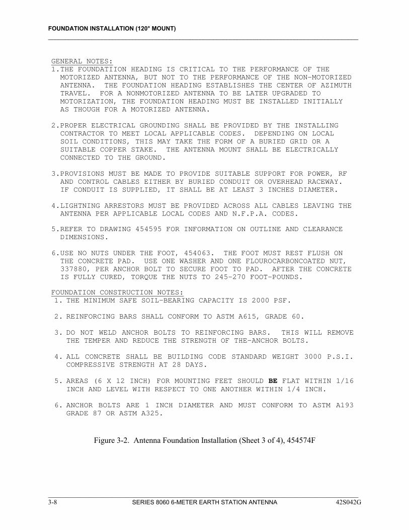
GENERAL NOTES: 1. THE FOUNDATIION HEADING IS CRITICAL TO THE PERFORMANCE OF THE
MOTORIZED ANTENNA, BUT NOT TO THE PERFORMANCE OF THE NON-MOTORIZED ANTENNA. THE FOUNDATION HEADING ESTABLISHES THE CENTER OF AZIMUTH TRAVEL. FOR A NONMOTORIZED ANTENNA TO BE LATER UPGRADED TO MOTORIZATION, THE FOUNDATION HEADING MUST BE INSTALLED INITIALLY AS THOUGH FOR A MOTORIZED ANTENNA.
2. PROPER ELECTRICAL GROUNDING SHALL BE PROVIDED BY THE INSTALLING
CONTRACTOR TO MEET LOCAL APPLICABLE CODES. DEPENDING ON LOCAL SOIL CONDITIONS, THIS MAY TAKE THE FORM OF A BURIED GRID OR A SUITABLE COPPER STAKE. THE ANTENNA MOUNT SHALL BE ELECTRICALLY CONNECTED TO THE GROUND.
3. PROVISIONS MUST BE MADE TO PROVIDE SUITABLE SUPPORT FOR POWER, RF
AND CONTROL CABLES EITHER BY BURIED CONDUIT OR OVERHEAD RACEWAY. IF CONDUIT IS SUPPLIED, IT SHALL BE AT LEAST 3 INCHES DIAMETER.
4. LIGHTNING ARRESTORS MUST BE PROVIDED ACROSS ALL CABLES LEAVING THE
ANTENNA PER APPLICABLE LOCAL CODES AND N.F.P.A. CODES.
5. REFER TO DRAWING 454595 FOR INFORMATION ON OUTLINE AND CLEARANCE DIMENSIONS.
6. USE NO NUTS UNDER THE FOOT, 454063. THE FOOT MUST REST FLUSH ON
THE CONCRETE PAD. USE ONE WASHER AND ONE FLOUROCARBONCOATED NUT, 337880, PER ANCHOR BOLT TO SECURE FOOT TO PAD. AFTER THE CONCRETE IS FULLY CURED, TORQUE THE NUTS TO 245-270 FOOT-POUNDS.
FOUNDATION CONSTRUCTION NOTES: 1. THE MINIMUM SAFE SOIL-BEARING CAPACITY IS 2000 PSF. 2. REINFORCING BARS SHALL CONFORM TO ASTM A615, GRADE 60. 3. DO NOT WELD ANCHOR BOLTS TO REINFORCING BARS. THIS WILL REMOVE
THE TEMPER AND REDUCE THE STRENGTH OF THE-ANCHOR BOLTS. 4. ALL CONCRETE SHALL BE BUILDING CODE STANDARD WEIGHT 3000 P.S.I.
COMPRESSIVE STRENGTH AT 28 DAYS. 5. AREAS (6 X 12 INCH) FOR MOUNTING FEET SHOULD BE FLAT WITHIN 1/16
INCH AND LEVEL WITH RESPECT TO ONE ANOTHER WITHIN 1/4 INCH. 6. ANCHOR BOLTS ARE 1 INCH DIAMETER AND MUST CONFORM TO ASTM A193
GRADE 87 OR ASTM A325.
Figure 3-2. Antenna Foundation Installation (Sheet 3 of 4), 454574F
____________________________________________________________________________________________ 3-8 SERIES 8060 6-METER EARTH STATION ANTENNA 42S042G

FOUNDATION INSTALLATION (120° MOUNT) ____________________________________________________________________________________________
Figure 3-2. Antenna Foundation Installation (Sheet 4 of 4), 454574F
____________________________________________________________________________________________ 42S042G SERIES 8060 6-METER EARTH STATION ANTENNA 3-9
FOUNDATION INSTALLATION (120° MOUNT) ____________________________________________________________________________________________
NOTE
The AC disconnect box is not supplied by ViaSat.
Figure 3-3. Recommended Conduit Placement Locations for 120° Antenna, 454574F
____________________________________________________________________________________________ 3-10 SERIES 8060 6-METER EARTH STATION ANTENNA 42S042G
SECTION 4 FOUNDATION INSTALLATION (180° MOUNT)
4-1 General 4-1 Antenna Considerations 4-1 Foundation Design Considerations 4-19 Foundation Construction
42S042F SERIES 8060 6-METER EARTH STATION ANTENNA
____________________________________________________________________________________________
____________________________________________________________________________________________ 42S042G SERIES 8060 6-METER EARTH STATION ANTENNA 4-1
SECTION 4 FOUNDATION INSTALLATION (180° MOUNT)
GENERAL The pointing accuracy of the installed antenna is determined by the stiffness of the mount, the reflector, and the foundation. Therefore, antenna foundation preparation is an essential part of antenna installation.
ANTENNA CONSIDERATIONS
The foundation heading is critical to the performance of the motorized antenna, but not to the performance of the non-motorized antenna. The foundation heading establishes the center of azimuth travel. Proper electrical grounding shall be provided by the installing contractor to meet local applicable codes. Depending on local soil conditions, this may take the form of a buried grid or a suitable copper stake. The antenna mount shall be electrically connected to the ground. Provisions must be made to provide suitable support for power, RF, and control cables either by buried conduit or overhead raceway. If conduit is supplied, it shall be at least 3 inches in diameter. Lightning arrestors must be provided across all cables leaving the antenna per applicable local codes and N.F.P.A. codes. (Refer to Section 2 for information on required operational clearances.)
FOUNDATION DESIGN
CONSIDERATIONS
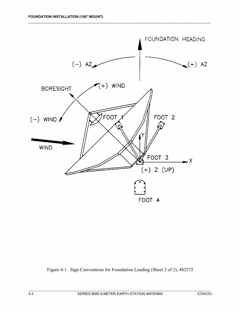
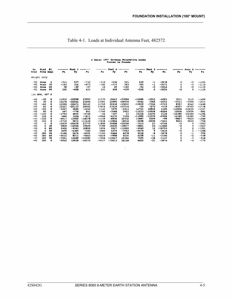
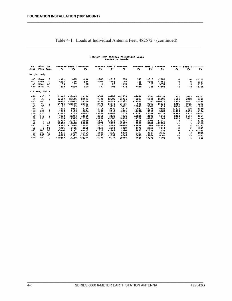
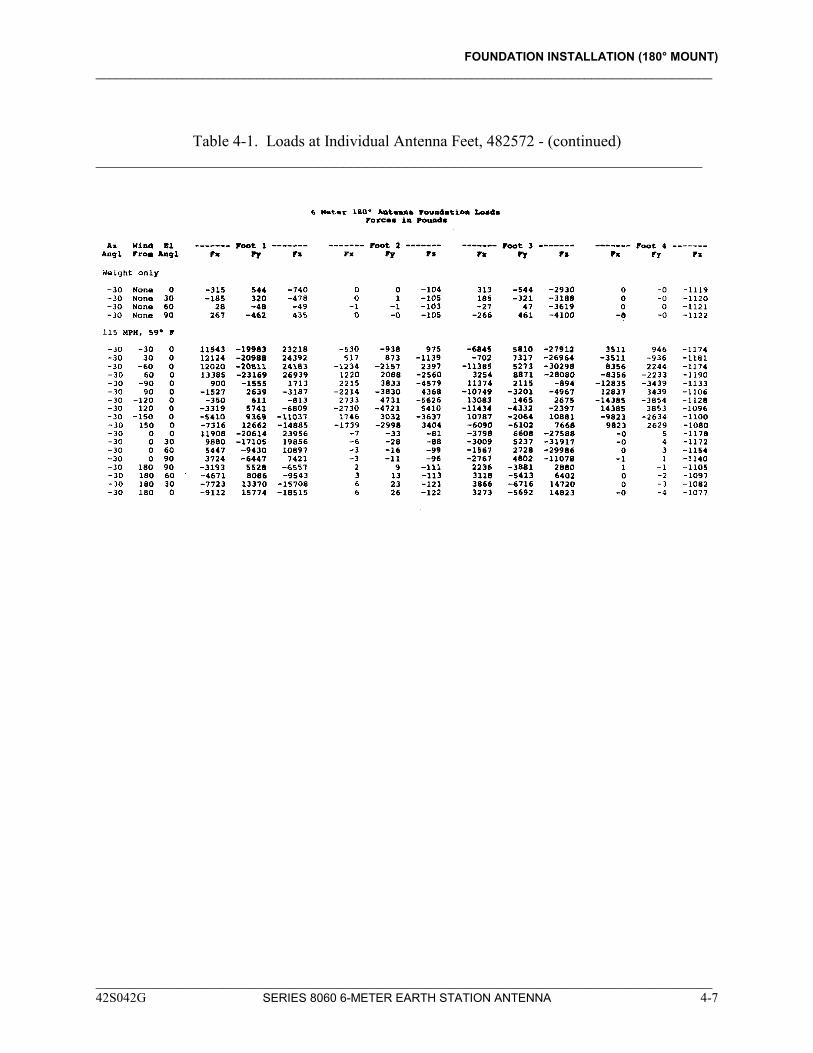
The antenna is designed to withstand an effective velocity pressure of 31 pounds per square foot (151.4 kg/m2) in any orientation, or 40 pounds per square foot (195.3 kg/m2) if stowed. These pressures represent 110 and 125 mile per hour (176 and 200 km/h)winds respectively at standard air at ground level. The foundation should be designed to maintain the antenna integrity under these same loads, with a safety factor of at least 1.5, and also to not allow the mounting plane of the three antenna feet to tilt more than 0.15°. The loading for the above conditions is presented in Tables 4-1 and 4-2. Figure 4-1 depicts the sign conventions for the tables. The loads for each mounting foot are listed in Table 4-1 and the resultant foundation loads are listed in Table 4-2. If loads are required for wind pressures other than those listed, they may be calculated from the information in the tables using the following procedure:
FOUNDATION INSTALLATION (180° MOUNT) ____________________________________________________________________________________________
1. Subtract the corresponding Weight Only load components from the load components for the orientation of interest.
2. Divide the desired wind pressure by the wind pressure for the
orientation of interest. 3. Multiply each of the load components by the factor obtained in
step 2. 4. Add back the Weight Only components which were subtracted in
step 1. The following information presents a typical pad foundation design. If a special foundation design or load frame is required, a qualified structural engineer who is familiar with local structural codes should be employed. The foundation loading information below should be used in implementing the design.
NOTE The following tables list forces which are the loads applied to the foundation by the antenna. Forces are in pounds; moments are in pound-feet.
____________________________________________________________________________________________ 4-2 SERIES 8060 6-METER EARTH STATION ANTENNA 42S042G

FOUNDATION INSTALLATION (180° MOUNT) ____________________________________________________________________________________________
Figure 4-1. Sign Conventions for Foundation Loading (Sheet 1 of 2), 482572
____________________________________________________________________________________________ 42S042G SERIES 8060 6-METER EARTH STATION ANTENNA 4-3
FOUNDATION INSTALLATION (180° MOUNT) ____________________________________________________________________________________________
Figure 4-1. Sign Conventions for Foundation Loading (Sheet 2 of 2), 482572
____________________________________________________________________________________________ 4-4 SERIES 8060 6-METER EARTH STATION ANTENNA 42S042G
FOUNDATION INSTALLATION (180° MOUNT) ____________________________________________________________________________________________
Table 4-1. Loads at Individual Antenna Feet, 482572 ______________________________________________________________________________
____________________________________________________________________________________________ 42S042G SERIES 8060 6-METER EARTH STATION ANTENNA 4-5
FOUNDATION INSTALLATION (180° MOUNT) ____________________________________________________________________________________________
Table 4-1. Loads at Individual Antenna Feet, 482572 - (continued) ____________________________________________________________________________
____________________________________________________________________________________________ 4-6 SERIES 8060 6-METER EARTH STATION ANTENNA 42S042G
FOUNDATION INSTALLATION (180° MOUNT) ____________________________________________________________________________________________
Table 4-1. Loads at Individual Antenna Feet, 482572 - (continued) ____________________________________________________________________________
____________________________________________________________________________________________ 42S042G SERIES 8060 6-METER EARTH STATION ANTENNA 4-7

FOUNDATION INSTALLATION (180° MOUNT) ____________________________________________________________________________________________
Table 4-1. Loads at Individual Antenna Feet, 482572 - (continued) ____________________________________________________________________________
____________________________________________________________________________________________ 4-8 SERIES 8060 6-METER EARTH STATION ANTENNA 42S042G
FOUNDATION INSTALLATION (180° MOUNT) ____________________________________________________________________________________________
Table 4-1. Loads at Individual Antenna Feet, 482572 - (continued) ____________________________________________________________________________
____________________________________________________________________________________________ 42S042G SERIES 8060 6-METER EARTH STATION ANTENNA 4-9
FOUNDATION INSTALLATION (180° MOUNT) ____________________________________________________________________________________________
Table 4-1. Loads at Individual Antenna Feet, 482572 - (continued) ____________________________________________________________________________
____________________________________________________________________________________________ 4-10 SERIES 8060 6-METER EARTH STATION ANTENNA 42S042G
FOUNDATION INSTALLATION (180° MOUNT) ____________________________________________________________________________________________
Table 4-1. Loads at Individual Antenna Feet, 482572 - (continued) ____________________________________________________________________________
____________________________________________________________________________________________ 42S042G SERIES 8060 6-METER EARTH STATION ANTENNA 4-11
FOUNDATION INSTALLATION (180° MOUNT) ____________________________________________________________________________________________
Table 4-1. Loads at Individual Antenna Feet, 482572 - (continued) ____________________________________________________________________________
____________________________________________________________________________________________ 4-12 SERIES 8060 6-METER EARTH STATION ANTENNA 42S042G
FOUNDATION INSTALLATION (180° MOUNT) ____________________________________________________________________________________________
Table 4-1. Loads at Individual Antenna Feet, 482572 - (continued) ____________________________________________________________________________
____________________________________________________________________________________________ 42S042G SERIES 8060 6-METER EARTH STATION ANTENNA 4-13
FOUNDATION INSTALLATION (180° MOUNT) ____________________________________________________________________________________________
Table 4-1. Loads at Individual Antenna Feet, 482572 - (continued) ____________________________________________________________________________
____________________________________________________________________________________________ 4-14 SERIES 8060 6-METER EARTH STATION ANTENNA 42S042G
FOUNDATION INSTALLATION (180° MOUNT) ____________________________________________________________________________________________
Table 4-1. Loads at Individual Antenna Feet, 482572 - (continued) ____________________________________________________________________________
____________________________________________________________________________________________ 42S042G SERIES 8060 6-METER EARTH STATION ANTENNA 4-15
FOUNDATION INSTALLATION (180° MOUNT) ____________________________________________________________________________________________
Table 4-1. Loads at Individual Antenna Feet, 482572 - (continued) ____________________________________________________________________________
____________________________________________________________________________________________ 4-16 SERIES 8060 6-METER EARTH STATION ANTENNA 42S042G
FOUNDATION INSTALLATION (180° MOUNT) ____________________________________________________________________________________________
Table 4-1. Loads at Individual Antenna Feet, 482572 - (continued) ____________________________________________________________________________
____________________________________________________________________________________________ 42S042G SERIES 8060 6-METER EARTH STATION ANTENNA 4-17
FOUNDATION INSTALLATION (180° MOUNT) ____________________________________________________________________________________________
Table 4-1. Loads at Individual Antenna Feet, 482572 - (continued) ____________________________________________________________________________
____________________________________________________________________________________________ 4-18 SERIES 8060 6-METER EARTH STATION ANTENNA 42S042G
FOUNDATION INSTALLATION (180° MOUNT) ____________________________________________________________________________________________
NOTE
ViaSat, Inc. does not represent or warrant that any particular design or size of foundation is appropriate for any particular locality or installation.
FOUNDATION CONSTRUCTION
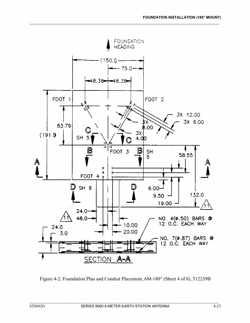
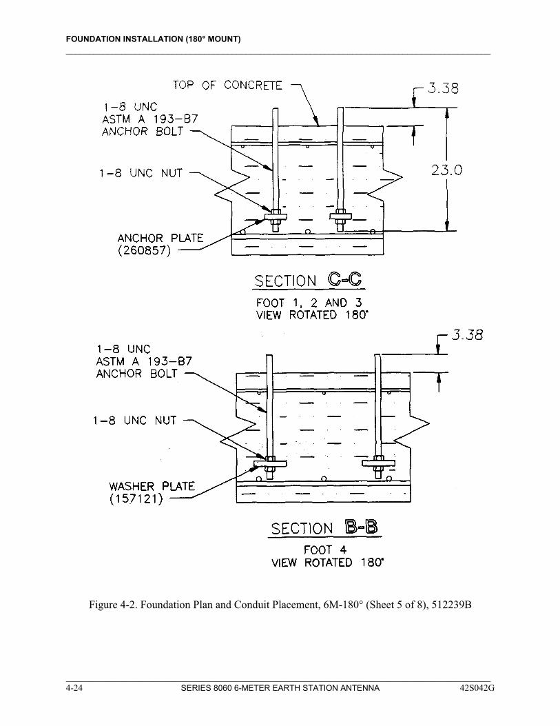
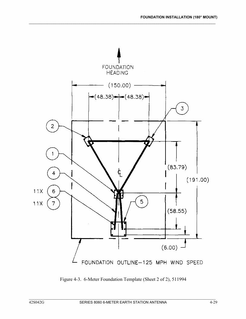
Refer to Figure 4-2 for the recommended foundation size and conduit placement. Refer to Figure 4-3 for 6-meter 180° foundation template.
____________________________________________________________________________________________ 42S042G SERIES 8060 6-METER EARTH STATION ANTENNA 4-19
FOUNDATION INSTALLATION (180° MOUNT) ____________________________________________________________________________________________
IMPORTANT NOTICE
ViaSat does not represent or warrant that any particular design or size of foundation is appropriate for any particular locality or installation.
VIASAT, INC.
Figure 4-2. Foundation Plan and Conduit Placement, 6M-180° (Sheet 1 of 8), 512239B
____________________________________________________________________________________________ 4-20 SERIES 8060 6-METER EARTH STATION ANTENNA 42S042G
FOUNDATION INSTALLATION (180° MOUNT) ____________________________________________________________________________________________
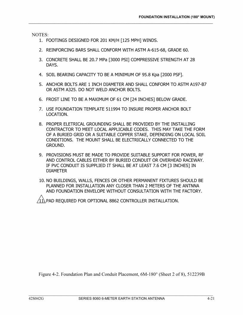
NOTES: 1. FOOTINGS DESIGNED FOR 201 KM/H [125 MPH] WINDS.
2. REINFORCING BARS SHALL CONFORM WITH ASTM A-615-68, GRADE 60.
3. CONCRETE SHALL BE 20.7 MPa [3000 PSI] COMPRESSIVE STRENGTH AT 28 DAYS.
4. SOIL BEARING CAPACITY TO BE A MINIMUM OF 95.8 Kpa [2000 PSF].
5. ANCHOR BOLTS ARE 1 INCH DIAMETER AND SHALL CONFORM TO ASTM A197-B7 OR ASTM A325. DO NOT WELD ANCHOR BOLTS.
6. FROST LINE TO BE A MAXIMUM OF 61 CM [24 INCHES] BELOW GRADE.
7. USE FOUNDATION TEMPLATE 511994 TO INSURE PROPER ANCHOR BOLT LOCATION.
8. PROPER ELETRICAL GROUNDING SHALL BE PROVIDED BY THE INSTALLING CONTRACTOR TO MEET LOCAL APPLICABLE CODES. THIS MAY TAKE THE FORM OF A BURIED GRID OR A SUITABLE COPPER STAKE, DEPENDING ON LOCAL SOIL CONDITIONS. THE MOUNT SHALL BE ELECTRICALLY CONNECTED TO THE GROUND.
9. PROVISIONS MUST BE MADE TO PROVIDE SUITABLE SUPPORT FOR POWER, RF AND CONTROL CABLES EITHER BY BURIED CONDUIT OR OVERHEAD RACEWAY. IF PVC CONDUIT IS SUPPLIED IT SHALL BE AT LEAST 7.6 CM [3 INCHES] IN DIAMETER
10. NO BUILDINGS, WALLS, FENCES OR OTHER PERMANENT FIXTURES SHOULD BE PLANNED FOR INSTALLATION ANY CLOSER THAN 2 METERS OF THE ANTNNA AND FOUNDATION ENVELOPE WITHOUT CONSULTATION WITH THE FACTORY.
11. PAD REQUIRED FOR OPTIONAL 8862 CONTROLLER INSTALLATION.
Figure 4-2. Foundation Plan and Conduit Placement, 6M-180° (Sheet 2 of 8), 512239B
____________________________________________________________________________________________ 42S042G SERIES 8060 6-METER EARTH STATION ANTENNA 4-21
FOUNDATION INSTALLATION (180° MOUNT) ____________________________________________________________________________________________
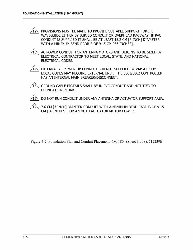
12. PROVISIONS MUST BE MADE TO PROVIDE SUITABLE SUPPORT FOR IFL
WAVEGUIDE EITHER BY BURIED CONDUIT OR OVERHEAD RACEWAY. IF PVC CONDUIT IS SUPPLIED IT SHALL BE AT LEAST 15.2 CM [6 INCH] DIAMETER WITH A MINIMUM BEND RADIUS OF 91.5 CM P36 INCHES].
13. AC POWER CONDUIT FOR ANTENNA MOTORS AND DEICING TO BE SIZED BY
ELECTRICAL CONTRACTOR TO MEET LOCAL, STATE, AND NATIONAL ELECTRICAL CODES.
14. EXTERNAL AC POWER DISCONNECT BOX NOT SUPPLIED BY VIASAT. SOME
LOCAL CODES MAY REQUIRE EXTERNAL UNIT. THE 8861/8862 CONTROLLER HAS AN INTERNAL MAIN BREAKER/DISCONNECT.
15. GROUND CABLE PIGTAILS SHALL BE IN PVC CONDUIT AND NOT TIED TO
FOUNDATION REBAR. 16. DO NOT RUN CONDUIT UNDER ANY ANTENNA OR ACTUATOR SUPPORT AREA. 17. 7.6 CM [3 INCH] DIAMTER CONDUIT WITH A MINIMUM BEND RADIUS OF 91.5
CM [36 INCHES] FOR AZIMUTH ACTUATOR MOTOR POWER.
Figure 4-2. Foundation Plan and Conduit Placement, 6M-180° (Sheet 3 of 8), 512239B
____________________________________________________________________________________________ 4-22 SERIES 8060 6-METER EARTH STATION ANTENNA 42S042G
FOUNDATION INSTALLATION (180° MOUNT) ____________________________________________________________________________________________
Figure 4-2. Foundation Plan and Conduit Placement, 6M-180° (Sheet 4 of 8), 512239B
____________________________________________________________________________________________ 42S042G SERIES 8060 6-METER EARTH STATION ANTENNA 4-23
FOUNDATION INSTALLATION (180° MOUNT) ____________________________________________________________________________________________
Figure 4-2. Foundation Plan and Conduit Placement, 6M-180° (Sheet 5 of 8), 512239B
____________________________________________________________________________________________ 4-24 SERIES 8060 6-METER EARTH STATION ANTENNA 42S042G
FOUNDATION INSTALLATION (180° MOUNT) ____________________________________________________________________________________________
Figure 4-2. Foundation Plan and Conduit Placement, 6M-180° (Sheet 6 of 8), 512239B
____________________________________________________________________________________________ 42S042G SERIES 8060 6-METER EARTH STATION ANTENNA 4-25
FOUNDATION INSTALLATION (180° MOUNT) ____________________________________________________________________________________________
Figure 4-2. Foundation Plan and Conduit Placement, 6M-180° (Sheet 7 of 8), 512239B
____________________________________________________________________________________________ 4-26 SERIES 8060 6-METER EARTH STATION ANTENNA 42S042G
FOUNDATION INSTALLATION (180° MOUNT) ____________________________________________________________________________________________
Figure 4-2. Foundation Plan and Conduit Placement, 6M-180° (Sheet 8 of 8), 512239B
____________________________________________________________________________________________ 42S042G SERIES 8060 6-METER EARTH STATION ANTENNA 4-27
FOUNDATION INSTALLATION (180° MOUNT) ____________________________________________________________________________________________
PARTS LIST
ITEM NO QTY PART NO. DESCRIPTION
1 1 475795 TEMPLATE BASE
2 1 260853 TEMPLATE, LH
3 1 260854 TEMPLATE, RH
4 2 268360 ANGLE, TEMPLATE
5 1 478590 TEMPLATE, BASE
6 11 173817 SCREW, HEX HD, 1/4-20 X 3/4
7 11 088711 NUT, HEX, 1/4-20
Figure 4-3. 6-Meter Foundation Template (Sheet 1 of 2), 511994
____________________________________________________________________________________________ 4-28 SERIES 8060 6-METER EARTH STATION ANTENNA 42S042G
FOUNDATION INSTALLATION (180° MOUNT) ____________________________________________________________________________________________
Figure 4-3. 6-Meter Foundation Template (Sheet 2 of 2), 511994
____________________________________________________________________________________________ 42S042G SERIES 8060 6-METER EARTH STATION ANTENNA 4-29