assembly instructions type 960 .96 meter class i and ii ... · assembly instructions type 960 .96...
TRANSCRIPT

Assembly Instructions
Type 960 .96 Meter Class I and II Antenna System Type 123 1.2 Meter Class I and II Antenna Systemwith Factory Assembled Az/El Cap Mount
8000842-01
Skyware Global1315 Industrial Park DriveSmithfi eld, NC 27577 USA
Telephone: +1-919-934-9711 Internet: www.skywareglobal.com
Printed in U.S.A.
04/11 8000842-01 Rev G EC-01063
™

1
Skyware GlobalVERY SMALL APERTURE TERMINAL (VSAT) PRODUCTS
TWELVE (12) MONTH LIMITED WARRANTY
Seller warrants that all Skyware Global manufactured VSAT products are transferred rightfully and with good title; that they are free from any lawful security interest or other lien or encumbrance unknown to Buyer. Seller also warrants that for a period of twelve (12) months from the date of shipment from Seller’s factory, all its VSAT products shall be free from defects in material and workmanship which arise under proper and normal use and service. Buyer’s exclusive remedy hereunder is limited to Seller’s correction (either at its plant or at such other place as may be agreed upon between Seller and Buyer) of any such defects by repair or replacement at no cost to Buyer,
except for the costs of any transportation in connection with the return of the defective VSAT products to be replaced or repaired, and the costs to remove and/or reinstall the products, which shall be borne by Buyer. The limited warranty period shall not be extended
beyond its original term with respect to any part or parts repaired or replaced by seller hereunder.
This warranty shall not apply to VSAT products which (i) have been repaired or altered in any way so as to aff ect stability or durability, (ii) have been subject to misuse, negligence or accident, (iii) have been damaged by severe weather conditions such as
excessive wind, ice, storms, lightning, or other natural occurrences beyond Seller’s control; (iv) have presented damages, defects or nonconformances caused by improper shipping, handling or storage, and (v) have not been installed, operated or maintained in
accordance with Seller’s instructions.
Buyer shall present any claims along with the defective VSAT product(s) to Seller immediately upon failure Non-compliance with any part of this warranty procedure may invalidate this warranty in whole or in part.
SELLER MAKES NO WARRANTY, EXPRESS OR IMPLIED, OTHER THAN AS SPECIFICALLY STATED ABOVE. EXPRESSLY EXCLUDED ARE ANY IMPLIED WARRANTIES OF MERCHANTABILITY OR FITNESS FOR A PARTICULAR PURPOSE. THE FOREGOING SHALL
CONSTITUTE ALL OF SELLER’S LIABILITY (EXCEPT AS TO PATENT INFRINGEMENT) WITH RESPECT TO THE VSAT PRODUCTS. IN NO EVENT SHALL SELLER BE LIABLE FOR ANY LOSS OF PROFITS OR REVENUE, LOSS OF USE, INTERRUPTION OF BUSINESS, OR
INDIRECT, SPECIAL, CONSEQUENTIAL OR INCIDENTAL DAMAGES OF ANY KIND AS A RESULT OF THE USE OF THE PRODUCTS MANUFACTURED BY SELLER, WHETHER USED IN ACCORDANCE WITH THE INSTRUCTIONS OR NOT. UNDER NO CIRCUMSTANCES SHALL SELLER’S LIABILITY TO BUYER EXCEED THE ACTUAL SALES PRICE OF THE VSAT PRODUCTS
HEREUNDER.
In some jurisdictions, Buyer may have other rights under certain statutes that may imply non-excludable warranties. No representative is authorized to assume for Seller any other liability in connection with the VSAT products.
DATE DESCRIPTION REVISION08/06 ECN 9007484 Rev B11/07 5075515 Rev C05/08 5078314 Rev D09/08 5075934 Rev E01/10 654 Rev F 04/11 EC-01063 Rev G
MANUAL REVISION HISTORY
WARRANTY
DO NOT DISCARD CONTENTSThe product in this packaging was placed in the market after August 13, 2005. Its components must not be discarded with normal municipal or household waste.
Contact your local waste disposal agency for recovery, recycling, or disposal instructions.

LAW: Installation and installer must meet local codes and ordinances regarding safety! Installation of this product should be performed only by a professional installer and is not recommended for consumer Do-It-Yourself installations.
DANGER: WATCH FOR WIRES! Installation of this product near power lines is extremely dangerous and must never be attempted. Installa-tion of this product near power lines can result in death or serious injury! For your own safety, you must follow these important safety rules. Failure to follow these rules could result in death or serious injury.
1. Perform as many functions as possible on the ground.2. Watch out for overhead power lines. Check the distance to the power lines before starting installation. Stay at least 6 meters (20 feet) away from all power lines.3. Do not install antenna or mast assembly on a windy day.4. If you start to drop antenna or mast assembly, move away from it and let it fall.5. If any part of the antenna or mast assembly comes in contact with a power line, call your local power company. DO NOT TRY TO REMOVE IT YOURSELF! They will remove it safely.6. Make sure that the mast assembly is properly grounded.
WARNING: Assembling dish antennas on windy days is extremely dangerous and must never be attempted. Due to the surface area of the refl ector, even slight winds create strong forces. For example, this antenna facing a wind of 32 km/h (20 mph) can undergo forces of 269 N (60 lb). BE PREPARED TO SAFELY HANDLE THESE FORCES AT UNEXPECTED MOMENTS. ATTEMPTING TO ASSEMBLE, MOVE OR MOUNT A DISH ON WINDY DAYS COULD RESULT IN DEATH OR SERIOUS INJURY. Skyware Global is not responsible or liable for damage or injury resulting from antenna installations.
WARNING: Antennas improperly installed or installed to an inadequate structure are very susceptible to wind damage. This damage can be very serious or even life threatening. The owner and installer assumes full responsibility that the installation is structurally sound to support all loads (weight, wind and ice) and properly sealed against leaks. Skyware Global will not accept liability for any damage caused by a satellite system due to the many unknown variable applications.
WARNINGS
2
PRE INSTALLATION CONSIDERATIONS
TOOLS REQUIRED:
Compass 13 mm Deep Socket (3/8” Drive) 10 mm Nut Driver Torque WrenchClinometer #1 or #2 Phillips Screwdriver 10 mm Socket (3/8” Drive) 9” Magnetic Level3/8” Drive Ratchet Wrench 13 mm Combination Wrench 10 mm Combination Wrench (2) 17 mm Open End Wrenches
ADDITIONAL INSTALLATION MATERIALS (Not Included with Antenna)
Installation Mount (Ground Pole, King Post, Wall Mount or Roof Mount)Grounding Rod, Clamp & Grounding Block - As required by National Electric Code or local codes.Ground Wire - #10 solid copper or #8 aluminum as required by National Electric Code or local codes (length as required).RG-6 Coaxial Cables from antenna to indoor units.Concrete: See “Ground Pole” section for quantityM10 or #3 Rebar: See “Ground Pole” section for quantity. Deformed steel per ASTM A615, Grade 40 or 60.
SITE SELECTION
The fi rst and most important consideration when choosing a prospective antenna site is whether or not the area can provide an accept-able “look angle” at the satellites. A site with a clear, unobstructed view is preferred. Also consider obstruction that may occur in the future such as the growth of trees. Your antenna site must be selected in advance so that you will be able to receive the strongest signal available. To avoid obstructions, etc., conduct an on-site survey with a portable antenna. The satellite antenna can be installed on a ground pole, wall/roof mount, or non-penetrating roof mount with 2-7/8” or 3” outside diameter mast. The chosen mount type should be assembled and in place before installing the antenna. Refer to instructions packed with mount for its proper installation. The mast pipe must be vertical and plumb to insure ease of alignment.
As with any other type of construction, a local building permit may be required before installing an antenna. It is the property owner’s responsibility to obtain any and all permits.
Before any digging is done, information regarding the possibility of underground telephone lines, power lines, storm drains, etc., in the excavation area should be obtained from the appropriate agency.
Because soils vary widely in composition and load capacity, consult a local professional engineer to determine the appropriate foundation design and installation procedure. A suggested foundation design with conditions noted is included in this manual for reference purposes only.

1.2 mAntenna
3
7.3 cm or 7.6 cm(2.88” or 3.00” O.D.)
91.4 cm max.(36”)182.9 cm
(72”)
102 cm(40”)
#3 rebar x diameter
of pier. Insert throughhole in tube and center.
#3 Rebar
DMinimumDiameter
25 mmto 51 mm
(1” to 2”) slope for water run-off
Grade
Below Frost Line
182.9 cm(72”)
25 mm to 51 mm (1” to 2”) slope for water run-off
Grade
7.3 cm or 7.6 cm(2.88” or 3.00” O.D.)
DMinimumDiameter
Below Frost Line
Approx.51 mm
(2”)
127 cm(50”) (See Note)
#3 rebar x .46 m (18”)Insert through
hole in tube and center.
#3 Rebar
#3 rebar x .6 m (24”)at 60˚ apart (See note)
51 mm(2”)
Bubble Level
Ground Pole Must Be Vertical in All Directions
at Top
NOTE: 127 cm (50”) may
be increased to frost line. Concrete and length of rebar will
increase accordingly.
Bottom View
NOTE:1. Poles are not supplied (purchase locally to above specifi cations) and must be fi eld drilled 5/8” diameter for M10 #3 rebar, 5.5 mm for self tapping grounding screw and (.218”) for 1/4-20 self tapping grounding screw. Poles and screws must be galvanized or painted for protection.
2. Pole and foundation design based on the following criteria: a. Uniform building code Exposure B or C wind loading. b. Vertical soil pressure of 13790 kPa (2000 pounds per square foot). c. Lateral soil pressure of 2758 kPa (400 pounds per square foot). d. Concrete compressive strength of 17.2 MPa (2500 pounds per square inch) in 28 days.
3. See page 6 for grounding recommendations.
CAUTION: The foundation design shown does not represent an appropriate design for any specifi c locality. Soil conditions vary and may not meet design criteria given in Note 2. Consult a local professional engineer to determine your soil conditions and appropriate foundation.
GROUND POLE INSTALLATION
Pier Foundations Deep Frost Line Foundations
WIND VEL DIM D CONC VOL DIM D CONC VOL DIM D CONC VOL DIM D CONC VOL GROUNDkm/h (mph) cm (in) m3 (ft3) cm (in) m3 (ft3) cm (in) m3 (ft3) cm (in) m3 (ft3) POLE
161 (100) 25 (10) 0.05 (1.8) 38 (15) 0.12 (4.1) 18 (7) 0.03 (1.1) 25 (10) 0.06 (2.2) A, B or C
201 (125) 36 (14) 0.10 (3.7) 51 (20) 0.21 (7.4) 23 (9) 0.05 (1.9) 36 (14) 0.13 (4.6) A, B or C
161 (100) 30 (12) 0.07 (2.5) 46 (18) 0.17 (6.0) 20 (8) 0.04 (1.4) 33 (13) 0.11 (3.8) A ,B or C
201 (125) 43 (17) 0.15 (5.2) 61 (24) 0.30 (10.5) 30 (12) 0.09 (3.2) 48 (19) 0.23 (8.1) A or C
EXPOSURE B
96 cmAntenna
EXPOSURE C EXPOSURE B EXPOSURE C
POLE SPECIFICATIONS:
Ground Pole “A” 2-1/2 Schedule 40 Steel ASTM A53 Pipe (73 mm x 5 mm Wall/2.88” OD x .203” Wall)Ground Pole “B” 3.0” OD x 9 Gauge (.148” Wall) Steel ASTM A501 Pipe (76 mm OD x 3.8 mm Wall)Ground Pole “C” 2-1/2 Schedule 80 Steel ASTM A53 Pipe (73 mm x 7 mm Wall/2.88” OD x .276” Wall)
91.4 cm max.(36”)
Pier Foundations Deep Frost Line Foundations

The Az/El mount is factory confi gured to achieve elevation angles from 8° to 54°. For higher angles, the elevation adjustment screw setting must be modifi ed. (See table for elevation ranges). Before proceeding with antenna installation, determine the elevation angle for the site (refer to main installation instructions). If the elevation setting for the site is greater than ~ 52º, follow these steps:
Antenna Model Range As Shipped Range At High Angle Setting
1.2 m Type 123 8˚ to 54˚ 42˚ to 85˚
96 cm Type 960 8˚ to 54˚ 34˚ to 85˚
Adjustment procedure:
1 Loosen two elevation clamp nuts (in curved slots), and loosen elevation pivot bolts2 Swing the housing up against the underside of the elevation adjustment screw head3 Set the az/el mount on the side closer to the elevation adjustment bolt4 Loosen the bottom nut on the elevation adjustment screw. (Use two open-end wrenches to release the double nuts)5 Run the top nut up tight against the az/el housing and elevation screw head, then back off nut half a turn6 Run bottom nut along the elevation screw against top nut7 While holding the top nut in place with a wrench fi rmly tighten the bottom nut against it to lock them both in that position.8 The az/el is now confi gured for high elevation angles. Proceed with the installation as instructed in the installation manual.
Bottom Nut Top Nut
High Elevation Angle SettingFactory Setting of Elevation Screw
Clamp Nut(2 Places)
ElevationPivot Bolts(2 Places)
Note new position of top and bottom nut.
ElevationPivot Bolts(2 Places)
Top Bracket
U Bracket
Carriage Bolt and Hex Nut (4 Places)
Half Clamp(2 Places) Clamp Bolts
(Carriage Bolt and Hex Nut)(4 Places)
Hex Nut Swivel Nut
Loosen (4) carriage bolts and nuts securing the “U” bracket to the top bracket. Loosen (4) carriage bolts and nuts securing “U” Bracket to (2) half clamps. Loosen swivel nut and hex nut. Install AZ/EL cap mount onto ground pole. Equally tighten (4) clamp bolts so that cap is held station-ary on ground pole, but can be swiveled with slight pressure (approximately 2.7 N-m (2 ft-lb). Retighten and torque (4) carriage bolts and nuts securing “U” bracket to half clamps to 24.4 Nm (18 ft-lb). Leave loose (4) carriage bolts, swivel nut and hex nuts, for fi ne tune option.
4

ASSEMBLY AND INSTALLATION
Assembling Refl ector Onto Az/El Cap Mount
Install four M8 x 60 mm plow bolts into holes in refl ector face. Lift refl ector and insert exposed portion of bolt into holes in az/el mounting fl ange. Secure refl ector to az/el mount with 4 lock washers and hex nuts onto plow bolts. Tighten and torque to 15 N-m (11 ft-lb). Press fi t hole plugs in remaining four unused holes of the refl ector.
IMPORTANT: Note orientation of feed leg mounting holes in refl ector rim. Top of refl ector does NOT have feed leg mounting hole.
Az/El Cap Mount
Installation Pole
M8 x 60 mm Plow Bolts(4 Places)
Hex Nut (4 Places)
Lock Washer (4 Places)
M8 x 60 mm Plow Bolts(4 Places)
Hole Plugs(4 Places)
Front View of Refl ector Rear View of Refl ector
5
Installing Az/El Cap Mount Onto Pole
Before installing az/el cap onto pole, installation mount should be in place. Loosen (4) hex nuts on pipe clamp. Install az/el cap onto pole. Equally tighten (4) clamp bolts so that cap is held stationary on pole, but can be swiveled with slight pressure. Tighten approximately 2.7 N-m (2 ft-lb ).
Insert (2) M8 set screws into threaded inserts in pipe clamp. Do not tighten.
Back View
M8 Set Screws(2 Places)
Clamp Bolts(4 Places)

Class I Feed Legs Installation
Assemble side feed legs to side rim of refl ector and bottom feed leg to bottom rim of refl ector. From the inside of refl ector rim, insert M6 x16 mm hex bolt through washer, hole in rim and feed leg hole. Secure with lock washer and hex nut.
ASSEMBLY AND INSTALLATION for Class I Antennas
Class I Junction Block and Feed Leg Installation
Insert bottom feed leg into junction block and twist until lance engages.
NOTE: Bottom feed leg is the one with a slight bend and a lance on one end. It is shorter than the side feed legs. The end with the lance inserts in junction block and end with bend attaches to refl ector.
Class I Feed Assembly Installation
Attach side feed legs to junction block with M6 x 16 mm Hex Head Bolt and M6 Lock Washer.
NOTE: Long formed end of side feed leg attaches to the refl ector rim, short formed end to side of junction block.
Tighten and torque all hardware to junction block and refl ector to 5.4 N-m (4 ft-lb). Tighten two M4 pan head screws in junction block socket equally.
Attach feed assembly to junction block with two M6 x 16 mm hex head bolts, two lock washers and mounting block clamp as shown on right. Refer to instructions packed with feed assembly.
M6 x 16 mmHex Bolt
M6 x 16 mmHex Bolt
Flat Washer
Lock Washer
M6 Hex Nut
Flat Washer
Lock WasherM6 Hex Nut
M6 x 16 mmHex Bolt
Lock Washer
Mounting Block ClampM6 x 16 mm
Hex Bolt
Lock Washer
6
M4 Pan HeadScrew

7
Class II Side Feed Legs and Mount Braces InstallationBefore attaching side feed legs, locate mount braces and identify left and right parts. Attach one end of each brace (fl attened oval end with slotted hole) to the az/el mount housing with carriage bolt, star washer, washer, lock washer and hex nut as shown below. Note that star washer is located between az/el mount and rear braces as illustrated. Do not tighten. Swing opposite end of mount brace in position to align fl ange holes with holes in side rim of refl ector as shown.
NOTE: Long formed end of side feed leg attaches to the refl ector rim, short formed end to side of feed support junction block.
From the inside of refl ector rim, insert M6 x 16 mm hex bolt through fl at washer and aligned slot of mount brace, refl ector rim side hole and hole in feed support leg. Secure side feed legs and mount braces to refl ector side rim with lock washer and hex nut. Do not tighten.
Left Mount Brace
M6 x 22 mmRound Head Square NeckBolt (2 Places)
M6 Hex Nut (2 Places)
M6 Lock Washer (2 Places)
M6 Flat Washer (2 Places)
M6 x 16 mmHex Bolt
Flat Washer
Lock Washer
M6 Hex Nut
Mount Brace
Side Feed Leg
IMPORTANT: DO NOT assemblebottom feed support tube until instructed to do so. Early assembly may cause damage to refl ecter.
ASSEMBLY AND INSTALLATION for Class II Antennas
M6 Star Washer (2 Places)
Right Mount Brace

8
Class II Side Feed Legs, Support Block and Feed Assembly Installation
Attach support block to support tube with two M6 x 16 mm hex bolts and two M6 lock washers. Tighten hardware.
Attach side feed legs to support block with two M6 x 20 mm hex bolts and two M6 lock washers. Do not tighten.
Now tighten feed support and mount brace hardware.
Attach feed assembly to support block with two M6 x 30 mm hex head bolts, two lock washers and a mounting block clamp as shown below.
Refer to instructions packed with feed assembly.
With side feed legs and support block in place, swing support tube as shown and align support tube hole with bottom rim hole of refl ector rim. Attach support tube to refl ector with M6 x 16 mm hex bolt, fl at washer, lock washer and M6 hex nut.
M6 x 16 mmHex Bolt
Flat Washer
Lock Washer
M6 Hex Nut
Support Tube
ASSEMBLY AND INSTALLATION for Class II Antennas
Rear View Detail of Support Tubeand Refl ector Assembly
M6 x 30 mmHex Bolt
Lock Washer
Mounting Block Clamp

9
Fine Tuning
Use Signal Tuning Device for fi nal adjustments to obtain maximum antenna performance. Alternate between elevation and azimuth fi netuning to reach maximum signal strength, until no improvement can be detected. Azimuth is fi ne tuned by loosening the (4) carriage head bolts and swivel nut which allows adjusting the azimuth fi ne tune adjusting bolt for the peak signal. When fi ne tuning is complete, tighten and torque all az/el hardware to 16.3 N-m (12 ft-lb). Do not exceed 16.3 N-m (12 ft-lb). Torque Clamp Hardware to 24.4 N-m (18 ft-lb) in alternating sequence.
IMPORTANT: Recheck and repeat torque on four clamp bolts, in alternating sequence, until all bolts are equally torqued to 18 ft-lb.
Rotate Antenna On Ground Tube
Azimuth
Example Depicts Azimuth Heading To 171˚(Azimuth ± Magnetic Deviation)
Compass
ANTENNA ALIGNMENT PROCEDURE
Azimuth - Initial Setting
Use Chart 3 and determine your azimuth setting. Values in chart must be adjusted for magnetic deviation for your location for correct compass reading. Rotate refl ector and mount pointing it to the correct compass reading. Slowly sweep the antenna in azimuth until signal is found. If the desired signal is not found, increase or decrease elevation setting and repeat the azimuth sweep. Tighten half clamp bolts and set screws.
Top Bracket
Hex Nut Swivel Nut
Half Clamp Bolts
Azimuth Fine Tune Adjusting Bolt
Satellite Alignment
Alignment with the satellite is obtained by setting polarization, elevation, and azimuth. Charts are provided in this manual to determine the values for your earth station antenna site. “ΔL” is the diff erence between the earth station antenna site longitude and the satellite longitude. Use “ΔL” and your earth station latitude to obtain polarization, elevation or azimuth setting.
Polarization of Feed
Loosen feed Horn clamp bolts and turn feed clockwise or counterclockwise, depending on being east or west of the satellite as shown on Chart 1. For coarse setting, align marks on the horn scale. Polarization chart assumes antenna system polarization is transmit vertical and satellite vertical Pol is perpendicular to plane of geostationary arc. For horizontal transmit of antenna, feed must be rotated 90° from values shown. (Starting point for polarization adjustment is 0°, as shown. Use a signal strength measuring device for fi nal polarization setting and tighten horn clamp bolts to 5.4 N-m (4 ft-lb).
Horn Scale
Alignment Mark
Clamp Bolt
Top View of Feed Assembly
Elevation - Initial Setting
Use Chart 2 and determine your elevation setting. Loosen elevation pivot bolts and bolts in curved slots (both sides) of az/el housing approximately 1 complete turn. Turn elevation adjustment bolt clockwise to decrease elevation and counter-clockwise to increase elevation. Align the edge of the clamp with appropriate mark on housing at the desired elevation reading. This will be an approximate setting. Optimum setting achieved when fi ne tuning.
NOTE: Degree values shown on Elevation Scale are Beam; there is no need to compensate for any off set angle. (See Appendix A, Outline Drawing). If clinometer is used, you must compensate for off set angle.
Elevation Adjustment Screw
Curved Slot Bolt
Elevation Pivot Bolt
Clamp Bolt(4 Places)
Edge of Clamp Bracket IndicatesDegree of Elevation
Example: 18˚ Elevation
Set Screw(2 Places)

GROUNDING PROCEDURE
INSTALLATION POLE MOUNT
TRIMAST WALL MOUNT
Non Penetrating Roof Mount
Ground Wire
Ground Wirewith Ring Clip
Ground Lug
1/4”DrillingScrew
ToothWasher
ToothWasher
Ground Wirewith Ring Clip
Ground Lug
M6 LockNut
M6 x 16 mmHex Head Screw
M6 x 16 mmSelf Tapping Screw
Ground Lug
Ground Wirewith Ring Clip
ToothWasher
Note: Grounding wire and hardware are not supplied for pole mount, trimast wall mount or non penetrating roof mount. Installation mount and associated hardware are not supplied.
Ground Wire
SecureClampGrounding Rod
Ground Wire(NEC Section 810-20)
Ground Block(NEC Section 810-20)
Coaxial Cables (To IDU)
Coaxial Cables
(From ODU)
Note: Ground wire, secure clamp, grounding rod, coaxial cables andground block are not supplied.
IMPORTANT: All antenna sytems must be properly grounded. Refer to NEC (National Electric Code) Article 810, 820 and local building codes for specifi c requirements. Typical grounding methods are shown as examples. Tighten all hardware securely to assure good continuity.
10
TO GROUNDING ROD
TO G
ROU
ND
ING
RO
D
Class II
Class I
945 mm(37.2 in)
FV
MO
Elevation Degrees Force Moments N (Pounds) N-m (Foot-Pounds)
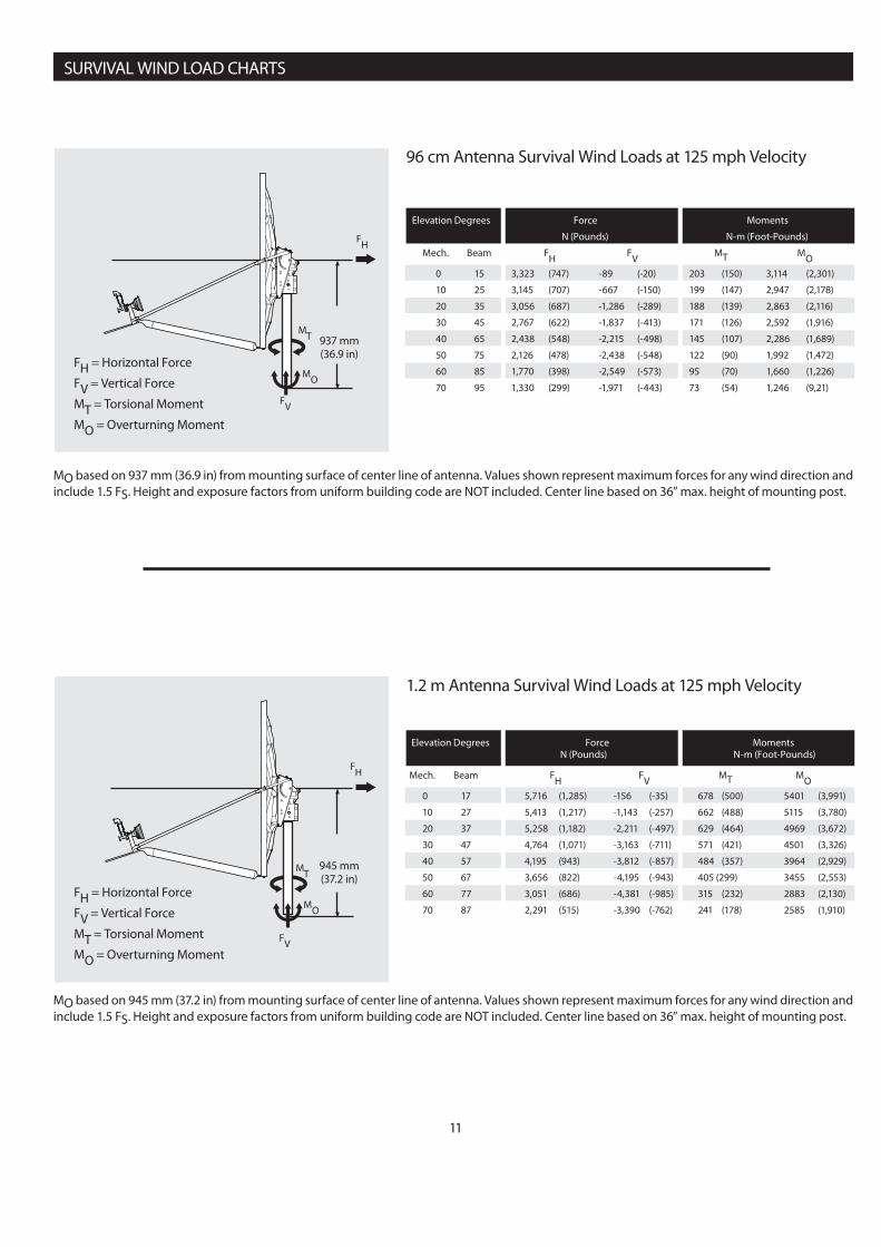
Mech. Beam FH FV MT MO 0 17 5,716 (1,285) -156 (-35) 678 (500) 5401 (3,991)
10 27 5,413 (1,217) -1,143 (-257) 662 (488) 5115 (3,780)
20 37 5,258 (1,182) -2,211 (-497) 629 (464) 4969 (3,672)
30 47 4,764 (1,071) -3,163 (-711) 571 (421) 4501 (3,326)
40 57 4,195 (943) -3,812 (-857) 484 (357) 3964 (2,929)
50 67 3,656 (822) -4,195 (-943) 405 (299) 3455 (2,553)
60 77 3,051 (686) -4,381 (-985) 315 (232) 2883 (2,130)
70 87 2,291 (515) -3,390 (-762) 241 (178) 2585 (1,910)
11
FH = Horizontal Force
FV = Vertical Force
MT = Torsional Moment
MO = Overturning Moment
FV
MO
Elevation Degrees Force Moments
N (Pounds) N-m (Foot-Pounds)
Mech. Beam FH FV MT MO 0 15 3,323 (747) -89 (-20) 203 (150) 3,114 (2,301)
10 25 3,145 (707) -667 (-150) 199 (147) 2,947 (2,178)
20 35 3,056 (687) -1,286 (-289) 188 (139) 2,863 (2,116)
30 45 2,767 (622) -1,837 (-413) 171 (126) 2,592 (1,916)
40 65 2,438 (548) -2,215 (-498) 145 (107) 2,286 (1,689)
50 75 2,126 (478) -2,438 (-548) 122 (90) 1,992 (1,472)
60 85 1,770 (398) -2,549 (-573) 95 (70) 1,660 (1,226)
70 95 1,330 (299) -1,971 (-443) 73 (54) 1,246 (9,21)
96 cm Antenna Survival Wind Loads at 125 mph Velocity
1.2 m Antenna Survival Wind Loads at 125 mph Velocity
MT
MT
MO based on 945 mm (37.2 in) from mounting surface of center line of antenna. Values shown represent maximum forces for any wind direction and include 1.5 FS. Height and exposure factors from uniform building code are NOT included. Center line based on 36” max. height of mounting post.
MO based on 937 mm (36.9 in) from mounting surface of center line of antenna. Values shown represent maximum forces for any wind direction and include 1.5 FS. Height and exposure factors from uniform building code are NOT included. Center line based on 36” max. height of mounting post.
937 mm(36.9 in)
FH
FH
SURVIVAL WIND LOAD CHARTS
FH = Horizontal Force
FV = Vertical Force
MT = Torsional Moment
MO = Overturning Moment

12
POLARIZATION CHART
EARTH STATION LATITUDE IN DEGREES NORTH OR SOUTH OF EQUATOR
FEED ROTATION(Facing Antenna)
For + Polarization Rotate Counter ClockwiseFor - Polarization Rotate Clockwise
Antenna
Polarization Chart Sign Values (+ or -) Northern Hemisphere Southern Hemisphere
Antenna Site West of Satellite Longitude - +Antenna Site East of Satellite Longitude + -
Feed

13
ELEVATION CHART
Use of Elevation Chart
n Determine = the diff erence between your site longitude and the satellite
longitude.
n Find you latitude on horizontal axis.
n Follow your latitude up until you intersect the curve for your .
n Read Elevation value on vertical axis.
ELEV
ATIO
N IN
DEG
REES

14
ANTENNA ALIGNMENT PROCEDURE
“ “
IS T
HE
DIF
FERE
NCE
BET
WEE
N T
HE
EART
H S
TATI
ON
ANTE
NN
A SI
TE L
ON
GIT
UD
E AN
D T
HE
SATE
LLIT
E LO
NG
ITU
DE
EARTH STATION ANTENNA AZIMUTH IN DEGREES
EARTH STATION ANTENNA AZIMUTH IN DEGREES
EART
H S
TATI
ON
AN
TEN
NA
LAT
ITU
DE
IN D
EGRE
ES N
ORT
H O
R SO
UTH
OF
EQUA
TOR
AZI
MU
TH C
OLU
MN
REA
DIN
G W
HEN
EAR
TH S
TATI
ON
IS W
EST
OF
SATE
LLIT
E
AZI
MU
TH C
OLU
MN
REA
DIN
G W
HEN
EAR
TH S
TATI
ON
IS E
AST
OF
SATE
LLIT
E
AZIMUTH CHART

15
PARTS LIST for CLASS I
NO. DESCRIPTION QTY.
1 96 cm Refl ector or 1.2 m Refl ector 1
2 Azimuth/Elevation Assembly 1
3 M8 x 60 mm Plow Bolt 4
4 M8 Lock Washer 4
5 M8 Hex Head Nut 4
6 Plug Cap 4
7 96 cm or 1.2 m Side Feed Leg 2
8 96 cm or 1.2 m Bottom Feed Leg 1
9 M6 x 22 Hex Head Bolt 3
10 M6 Lock Washer 5
11 M6 Hex Head Nut 3
12 Junction Block with Pan Head Screws 1
13 M6 x 16 Hex Head Bolt 2
14 Mounting Block Clamp 1
15 Feed Assembly 1
16 M6 x 16 Hex Head Bolt 2
17 M6 Flat Washer 5
1
23
4
5
6
7
8
10
11
12
9
14
15
16
17
9 10
10
11
119
131010
13
17
17
17

16
PARTS LIST for CLASS II
NO. DESCRIPTION QTY.
1 96 cm Refl ector or 1.2 m Refl ector 1
2 Azimuth/Elevation Assembly 1
3 M8 x 60 mm Plow Bolt 4
4 M8 Lock Washer 4
5 M8 Hex Head Nut 4
6 Plug Cap 4
7 96 cm or 1.2 m Side Feed Leg 2
8 96 cm or 1.2 m Bottom Support Tube 1
NO. DESCRIPTION QTY.
9 M6 x 22 Hex Head Bolt 3
10 M6 Lock Washer 11
11 M6 Hex Head Nut 5
12 Feed Support Block 1
13 M6 x 20 Hex Head Bolt 2
14 Mounting Block Clamp 1
15 Feed Assembly 1
16 M6 x 30 Hex Head Bolt 2
1
2
3
3
5
5
6
7
8
9
9
9
10
1711
11
10
17
3
4
4
12
13
14
15
16
10
10
17
18
1 3
6
Refl ector Bolts and Plugs
NO. DESCRIPTION QTY.
17 M6 Flat Washer 7
18 M6 x 16 Hex Head Bolt 2
19 M6 x 22 Round Head Square Neck Bolt
2
20 Mount Brace 2
21 M8 x 20 Hex Head Bolt 2
22 Star Washer 2
1919
17
11
7
10
7
7
1110
21
17
10
10
20
17
20
1011
2222

PERIODIC INSPECTION & MAINTENANCE
To ensure peak performance of the antenna system and to maintain validity of the warranty, the user should perform a periodic inspection every 6 months or following any severe weather event, As a minimum the following items should be inspected.
1. Installation Mount
Check for loose hardware - tighten if necessary.Check integrity of anchor bolts or hardware securing mount to the building or foundationsCheck ballast of Non-Penetrating Roof Mounts - cracked or broken blocks must be replaced.Check hardware and structural members for signs of corrosion - repair or replace as needed
2. Antenna Back Structure or Az/El Mount
Check for loose hardware - tighten if necessary.Check for signs of structural damage such as bending or crackingCheck hardware and stuctural members for signs of corrosion - repair or replace as needed
3. Refl ector
Check intergrity of bolts securing refl ector to back structure or az/el mount. Tighten any loose hardware.Check for signs of damage such as cracking. Inspect refl ector face for impact damage.Check hardware for signs of corrosion - repair or replace as needed.
4. Feed Support Structure
Check for loose hardware - tighten if necessary.Check for signs of structural damage such as bending.Check hardware and stuctural members for signs of corrosion - repair or replace as needed
5. Feed & RF Components
Check for loose hardware - tighten if necessary.Check hardware for signs of corrosion - repair or replace as needed.Check feed lens or window for damage or signs of leaking.Check waveguide connections between feed and RF electronics
6. Electrical
Check for loose cables and connectors - tighten if necessaryCheck for tight grounding connectionsCheck cables for weathering or cracks
17