meter series 1250 antenna system - servsat manual for 2 4m antenna... · 2.4 meter series 1250...
TRANSCRIPT

PRODELIN. GENERAL DYNAMICS
4096-663
February 9, 2005 Revision A
Assembly Manual
2.4 METER SERIES 1250 ANTENNA SYSTEM
PRODELIN CORPORATION 1500 Prodelin Drive
Newton NC 28658

PRODELIN CORPORATION 4096-663
2.4M SERIES 1250
2.4 Meter 2 Piece Az/EI Installation Instructions
A
-
REV.
REVISED HARDWARE AND TABLES
ORIGINAL RELEASE
DESCRIPTION
08/05/04
DATE
/^^ CLT
APPROVED
2

PRODELIN CORPORATION 4096-663
2.4M SERIES 1250
2.4M SERIES 1250 ANTENNA SYSTEM
TABLE OF CONTENTS
SECTION TITLE
I GENERAL INFORMATION 1.0 INTRODUCTION 1.1 UNPACKING AND INSPECTION 1.2 MECHANICAL INSTALLATION TOOLS 1.3 SITE SELECTION 1.4 SUGGESTED MAST & FOUNDATION
REFLECTOR AND SUPPORT ASSEMBLY 2.0 PART LIST 2.1 AZ/EL POSITIONER INSTALLATION 2.2 REFLECTOR PETAL ORIENTATION 2.3 REFLECTOR SUPPORT ASSEMBLY
III FEED SUPPORT 3.0 PART LIST 3.1 FEED SUPPORT INSTALLATION
IV ANTENNA POINTING 4.0 ALIGNMENT TO SATELLITE 4A IN1TIALAUGNMENT
V MAINTENANCE 5.0 MAINTENANCE OVERVIEW 5.1 PERIODIC INSPECTION 5.2 REFLECTOR 5.3 MOUNT AND REFLECTOR SUPPORT 5.4 FEED AND FEED SUPPORT
3

PRODELIN CORPORATION 4096-663
2.4M SERIES 1250
4
PRODELIN CORPORATION 4096-663
2.4M SERIES 1250
SECTION I GENERAL INFORMATION
1.0 INTRODUCTION This manual describes the assembly and installation of Prodelin's 2.4M 2-Piece Rx/Tx offset antenna system with an Az/EI mount (series number 1250). The Prodelin 2.4M is a rugged, reliable antenna system that will operate at C-band and Ku-band frequencies with high efficiency and at the same time successfully withstand the effects of the environment.
These instructions are listed by sections that cover all areas of assembly and installation. Additional sections are included in the manual to provide information on antenna alignment to the satellite and maintenance.
1.1 UNPACKING AND INSPECTION
1. UNPACKING & INSPECTION - The antenna containers should be unpacked and inspected at the earliest date to ensure that all material has been received and is in good condition. A complete packing list for each major component is supplied.
2. FREIGHT DAMAGE - Any damage to materials while in transit should be immediately directed to the freight carrier. He will instruct you on the matters regarding any freight damage claims.
3. MATERIAL - MISSING OR DAMAGED - Any questions regarding missing or damaged materials that is not due to freight carrier should be directed to Prodelin's Customer Service Department at:
PRODELIN CORPORATION 1500 Prodelin Drive Newton NC 28658
USA (828) 464-4141
5
PRODELIN CORPORATION 4096-663
2.4M SERIES 1250
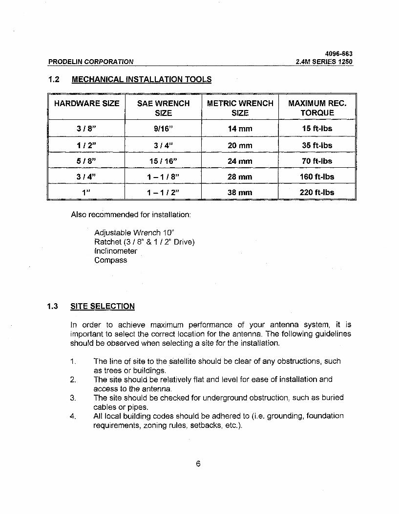
1-2 MECHANICAL INSTALLATION TOOLS
HARDWARE SIZE
3/8"
1/2" 5/8" 3/4"
1"
SAE WRENCH SIZE
9/16"
3/4" 15/16"
1-1/8" 1-1/2"
METRIC WRENCH SIZE
14mm
20 mm
24mm
28 mm
38 mm
MAXIMUM REC. TORQUE
15ft-lbs
35 ft-lbs
70 ft-lbs
160 ft-lbs
220 ft-lbs
Also recommended for installation:
Adjustable Wrench 10"
Ratchet (3 / 8" & 1 / 2" Drive) Inclinometer Compass
1.3 SITE SELECTION
In order to achieve maximum performance of your antenna system, it is
important to select the correct location for the antenna. The following guidelines should be observed when selecting a site for the installation.
1. The line of site to the satellite should be clear of any obstructions, such as trees or buildings.
2. The site should be relatively flat and level for ease of installation and access to the antenna.
3. The site should be checked for underground obstruction, such as buried cables or pipes.
4. All local building codes should be adhered to (i.e. grounding, foundation requirements, zoning rules, setbacks, etc.).
6
PRODEL1N CORPORATION 4096-663
2.4M SERIES 1250
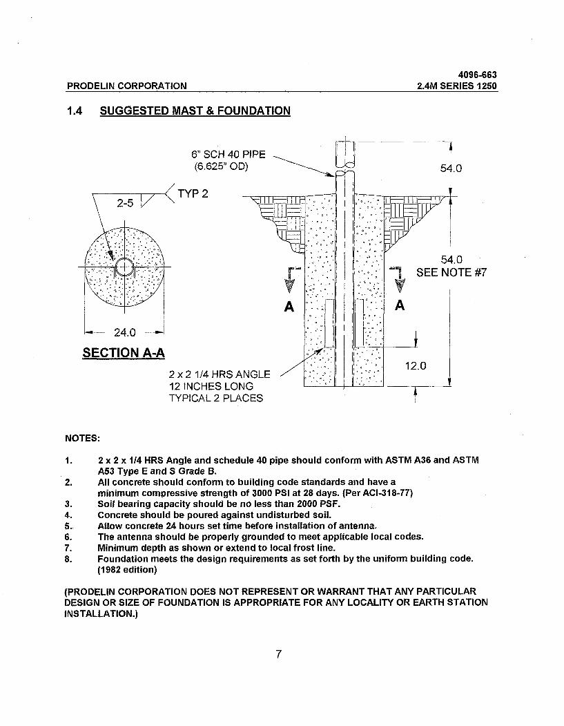
1.4 SUGGESTED MAST & FOUNDATION
24.0
SECTION A-A
6" SCH 40 PIPE (6.625" OD)
TYP2
2x21/4HRSANGLE 12 INCHES LONG TYPICAL 2 PLACES
\-| | | (———
^| \fr--.-;-.
P""
A
NGLE ^ \f~^ A\3 '————————i————
CES
11 -
]-- —
.'. °-. '• •
'.«•°. °' •
.
•
^.
^
..
^
.
°°
••
;:;- ^
. .»
•''«
°
P-
"»g
A
* 12.0
i
—
ipr' ^
l
^
i
I——11 V
\y
54 SEEN(
t
NOTES:
1. 2x2x1/4 MRS Angle and schedule 40 pipe should conform with ASTM A36 and ASTM A53 Type E and S Grade B.
2. All concrete should conform to building code standards and have a
minimum compressive strength of 3000 PSI at 28 days. (Per ACI-318-77) 3. Soil bearing capacity should be no less than 2000 PSF. 4. Concrete should be poured against undisturbed soil. 5- Allow concrete 24 hours set time before installation of antenna. 6. The antenna should be properly grounded to meet applicable local codes. 7. Minimum depth as shown or extend to local frost line. 8. Foundation meets the design requirements as set forth by the uniform building code.
(1982 edition)
(PRODEL1N CORPORATION DOES NOT REPRESENT OR WARRANT THAT ANY PARTICULAR DESIGN OR SIZE OF FOUNDATION IS APPROPRIATE FOR ANY LOCALITY OR EARTH STATION INSTALLATION.)

PRODELIN CORPORATION 4096-663
2.4M SERIES 1250
SECTION II REFLECTOR AND SUPPORT ASSEMBLY
REFLECTOR AND SUPPORT ASSEMBLY PART LIST- TABLE 2.0
ITEM PART NO. DESCRIPTION QTY
0179-381 0179-383
REFLECTOR "A" SIDE REFLECTOR "A" SIDE - WITH SHC
2 0179-382 0179-384
REFLECTOR "B" SIDE REFLECTOR "B" SIDE - WITH SHC
3 0490-183 Az / El POSITIONER
4 0159-283 THREADED INSERT 6
5 0490-601 SUPPORT TUBE
6 0250-657 TOP / BOTTOM CROSSARM 2
0181-249 ELEVATION ADJUSTMENT ASSEMBLY
8 0490-602 CROSSARM WELDMENT
9 8201-045 3/4 " FLATWASHER 6
10 8200-015 3/4" INTERNAL TOOTH LOCK WASHER
8
6
PRODELIN CORPORATION 4096-663
2.4M SERIES 1250
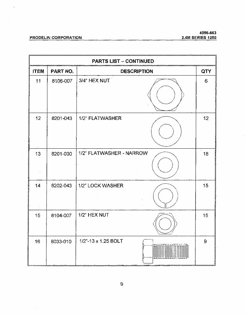
PARTS LIST - CONTINUED
ITEM PART NO. DESCRIPTION QTY
11 8106-007 3/4" HEX NUT 6
12 8201-043 1/2" FLATWASHER 12
13 8201-030 1/2" FLATWASHER-NARROW 18
14 8202-043 1/2" LOCK WASHER 15
15 8104-007 1/2" HEX NUT 15
16 8033-010 1/2"-13x1.25BOLT 9
9
PRODELIN CORPORATION 4096-663
2.4M SERIES 1250
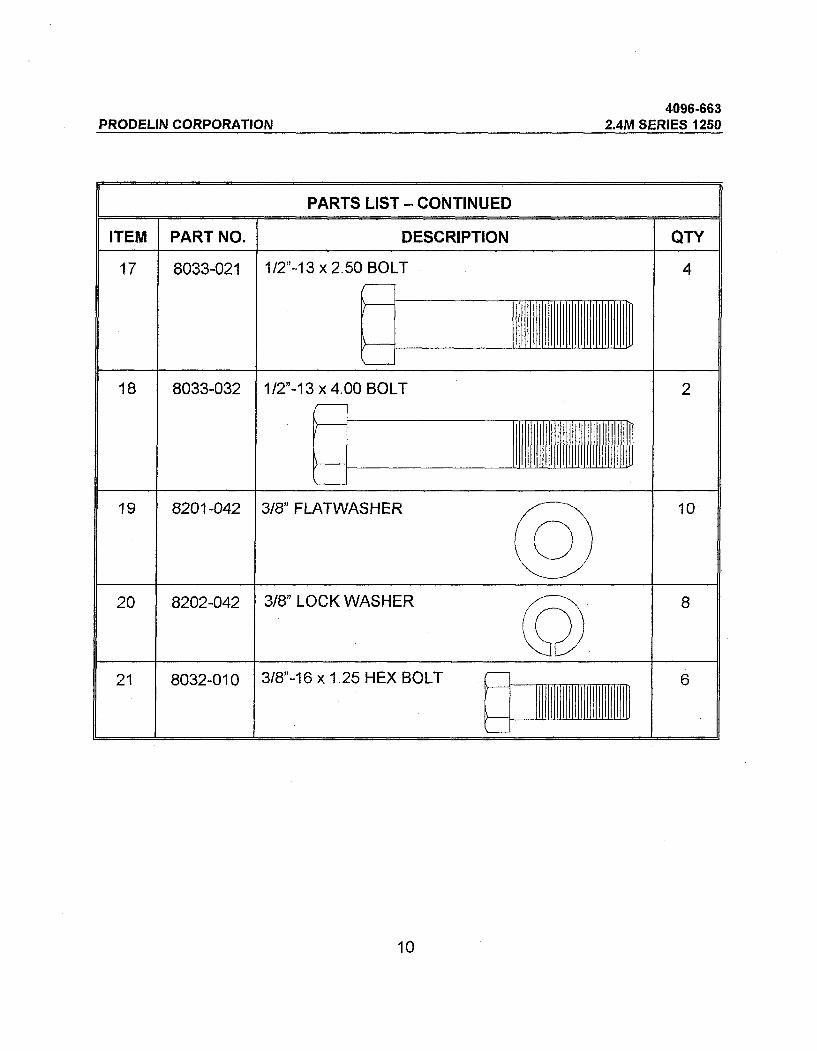
PARTS LIST - CONTINUED
ITEM
17
18
19
20
21
PART NO.
8033-021
8033-032
8201-042
8202-042
8032-010
DESCRIPTION
1/2"-13x2.50 BOLT
/
( 1/2"-13x4.00 BOLT
^ I 3/8" FLATWASHER ^—-\ @ 3/8" LOCK WASHER /""^
3/8"-16 x 1.25 HEX BOLT (—] ?"'
(—I
QTY
4
2
10
8
6
10

PRODELIN CORPORATION 4096-663
2.4M SERIES 1250
PARTS LIST - CONTINUED
ITEM
22
23
24
25
26
27
28
29
30
31
32
33
PART NO.
0490-168
8036-016
8036-072
8201-049
8202-046
8107-007
0188-093
0188-113
8032-014
8102-007
8033-020
8317-106
DESCRIPTION
ELEVATION TUBE
1-8X2.00 BOLT
1-8X9.00 BOLT
1" FLATWASHER
1" LOCKWASHER
1" HEX NUT
AZIMUTH ADJ. COLLAR
PIPE COLLAR
3/8-16 XI.75 BOLT
3/8" HEX NUT
Y2-13 X 2.50 FULL THREAD
SCREW ASSY 5/8-11 X 1.50"
QTY.
1
2
1
4
3
1
1
1
2
2
2
6
CAUTION: During Vr\e asserntety proc^^ure, the $e^M©n^ ^ in 1 '. ^ ' :..lfotic)wec^.ll^^^^t^l^^
, , ^';.^ ^. /^.th&^ntehr^^as^W^l^^j^^ . ;l<l^^;.
11

PRODELIN CORPORATION 4096-663
2.4M SERIES 1250
2.1 Az / El POSITIONER INSTALLATION
STEP1:
Insert the 5/8" Set Screws (ITEM #33) into the canister and slip Az/EI positioner over the mast pipe. Tighten the set screws snug against the mast pipe.
STEP 2:
Insert elevation tube using 1" hardware. Lightly tighten at this time.
STEP 3:
The positioner must be oriented correctly to the center of the satellite orbital arc. Loosen the set screws and rotate the canister on the mast pipe to the required position. Tighten the set screws then tighten the 5/8" lock nuts against the canister.
rdware On To Satellite Sides (within 5 deg.)
Az/EI Positioner
Elevation Tube
5/8" Set Screw Typical 6 Places
Mast Pipe
12

PRODELIN CORPORATION 4096-663
2.4M SERIES 1250
2.2 REFLECTOR PETAL ORIENTATION
The series 1250 reflector petals are labeled "A" and "B". In the standard upright position, the antenna elevation angle range is between 5 and 90 degrees. When viewed from behind in the standard position (feed support at the bottom), the "A"
petal (item 1) is on the left side and the "B" petal (item 2) is on the right side -
See Fig. 1.
However, to achieve a lower profile installation or in areas of high snow accumulation, the reflector can be assembled inverted (feed support on top) with the "B" petal on the left side and the "A" petal on the right side - See Fig. 2. Please note that in either situation, the angled cross arm (item 8) must be oriented for the correct position - See Fig. 3.
"A" Petal (item1)
Figure 1
13
"B" Petal (item 2)
Center of Reflector
Feed Rod Holes
Feed Support at Bottom

PRODELIN CORPORATION 4096-663
2.4M SERIES 1250
"B" Petal (item 2)
Feed Support on Top
"A" Petal (item 1)
Feed Rod Holes
Center of Reflector
Figure 2
Figure 3
Orientation of Angled Crossarm for Standard Position
Orientation of Angled Crossarm for Inverted Position

PRODELIN CORPORATION 4096-663
2.4M SERIES 1250
2.3 REFLECTOR SUPPORT ASSEMBLY
STEP1:
Place three of the threaded inserts (item 4) thru the face of each reflector petal (items 1 & 2) and secure with 3/4" hardware (items 9, 10 & 11). Snug only, Do not completely tighten at this time.
STEP 2:
Straddle the tabs of the reflector tube (item 5)over the holes in the positioner and secure using 1" bolt and hardware. Tighten snug only and let the tube fall back upon the positioner.
[24,25]
15

PRODELIN CORPORATION 4096-663
2.4M SERIES 1250
STEP 3:
Attach the top and bottom crossarms (item 6) to the reflector support tube with 1/2" hardware (items 12,14,15,17). Note orientation of crossarms. Do not tighten.
[6] 2 PL
STEP 4:
16
A) Place one reflector petal onto the Cross arms in either the standard or inverted position - see 2.2. Attach with 3/8" hardware (items 19,20,21) at each crossarm. Do not tighten
B) Place the second reflector petal on the cross arms and repeat above procedure.
PRODELIN CORPORATION 4096-663
2.4M SERIES 1250
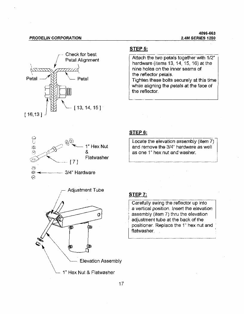
STEP 5: Check for best Petal Alignment
Petal
[13,14,15]
Attach the two petals together with 1/2" hardware (items 13, 14, 15, 16) at the nine holes on the inner seams of the reflector petals. Tighten these bolts securely at this time while aligning the petals at the face of | the reflector.
[16,13]
STEP 6;
1" Hex Nut &
Flatwasher
Locate the elevation assembly (item 7) and remove the 3/4" hardware as well as one 1" hex nut and washer.
Elevation Assembly
1" Hex Nut & Flatwasher
STEP 7:
Carefully swing the reflector up into a vertical position. Insert the elevation assembly (item 7) thru the elevation adjustment tube at the back of the positioner. Replace the 1" hex nut and flatwasher.
17

4096-663 2.4N1SER1ESJ250
pRODELiNCORPOBATI^ STEP81 —^-——-r^" FAS-^SS^ r^^x^ 3/4" hardware removed in step
1 Tighten securely. ^—
Support Tube
3/4" Hardware
ST£P^1 ___^——————1 ries^^ S^."^sr« ES^?'?".'5'"'1
^are (items 19, 20, 21).
^^htenth^^^^^^^^^^^ hardware by first t'9
reflector 3/4- hardware at thes^x ^ inserts foUowed by ^e^
S^^ sss-s. alignment^^—————•
18

PRODEL1N CORPORATION 4096-663
2.4M SERIES 1250
FOUNDATION PIPE
CANISTER
[30, 19,20,31]
19

PRODELIN CORPORATION 4096-663
2.4M SERIES 1250
SECTION III FEED SUPPORT ASSEMBLY
The following instructions are for installing a typical C-band or Ku-band feed support to Prodelin's 2.4 meter antenna system.
FEED SUPPORT PART LIST- TABLE 3.0
ITEM
1
2
3
4
5
6
7
8
PART NO.
VARIES
VARIES
VARIES
8032-010
8032-024
8201-042
8202-042
8102-007
DESCRIPTION
FEED SUPPORT
FEED ROD - Ku BAND
FEED ROD - C BAND
3/8" x 1.25 BOLT rU )———
3/8" x 3.00 BOLT
\I 3/8" FLATWASHER
3/8" LOCKWASHER
3/8" HEX NUT
QTY
1
2
2
4
1
10
5
5
20

PRODELIN CORPORATION 4096-663
2.4M SERIES 1250
3.1 Feed Support Installation
STEP1:
Attach the feed rods loosely to the reflector with 3/8" hardware (items- 4, 6, 7 & 8 ). See detail A
Feed Rods
STEP 2:
Position the feed support in front of the reflector and attach to the ends of the two feed rods with 3/8" hardware (items 5, 6, 7 & 8 ). See Detail B. Do not tighten.
See Detail B
Feed Support Tube
21

PRODELIN CORPORATION 4096-663
2.4M SERIES 1250
STEP 3:
Lift the end of the feed support tube and attach to the bottom of the reflector with 3/81 hardware (items -
4, 6, 7 & 8). See Detail C. Tighten all feed support hardware at this time.
Feed Rod
Feed Support Tube
See Detail C
DETAIL A
22
[4,6]

PRODELIN CORPORATION 4096-663
2.4M SERIES 1250
Feed Rods
[6,7,8]
Feed Support Tube
DETAIL B
Feed rods attach to last hole in feed support
DETAIL C [6,7,8]
Reflector
Feed Support Tube
NOTE: At this time you are ready to install your C-band or Ku-band feed system. For feed installation, reference any instructions that are enclosed with your specific feed
support._________________________________________ 23
PRODELIN CORPORATION 4096-663
2.4M SERIES 1250
SECTION IV ANTENNA POINTING
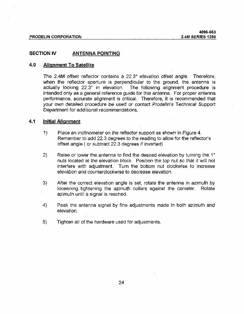
4.0 Alignment To Satellite
The 2.4M offset reflector contains a 22.3° elevation offset angle. Therefore, when the reflector aperture is perpendicular to the ground, the antenna is
actually looking 22.3° in elevation. The following alignment procedure is
intended only as a general reference guide for this antenna. For proper antenna performance, accurate alignment is critical. Therefore, it is recommended that your own detailed procedure be used or contact Prodelin's Technical Support Department for additional recommendations.
4.1 Initial Alignment
1) Place an inclinometer on the reflector support as shown in Figure 4. Remember to add 22.3 degrees to the reading to allow for the reflector's offset angle ( or subtract 22.3 degrees if inverted)
2) Raise or lower the antenna to find the desired elevation by turning the 1"
nuts located at the elevation block. Position the top nut so that it will not interfere with adjustment. Turn the bottom nut clockwise to increase elevation and counterclockwise to decrease elevation.
3) After the correct elevation angle is set, rotate the antenna in azimuth by loosening tightening the azimuth collars against the canister. Rotate azimuth until a signal is reached.
4) Peak the antenna signal by fine adjustments made in both azimuth and elevation.
5) Tighten all of the hardware used for adjustments.
24

PRODEUN CORPORATION
^clinometer
Etevation Adjustment
Azimuth Adjustment
25

PRODELIN CORPORATION 4096-663
2.4M SERIES 1250
SECTION V MAINTENANCE
5.0 Maintenance Overview
After installation, the antenna requires only periodic inspection. It is anticipated that maintenance, if required, will be minimal and easily handled by a local or in- house maintenance staff. The materials used in the construction of this Earth Station Antenna virtually eliminate any maintenance repairs.
5.1 Periodic Inspection
It is suggested that a periodic inspection be performed at least every six months.
NOTE: After any very severe weather conditions, inspection of the antenna should be performed to determine if foreign objects have caused damage or if
survival specifications have been exceeded.
This inspection should include the following:
1) Check all bolting locations - all bolts should be tight.
2) Check all structural members - repair or replace if damaged,
3) Check the foundation anchor bolts - they must be secure and with no failure signs in foundation.
4) Check for corrosion - on the reflector structure and mount.
5.2 Reflector
Prodelin's reflector does not require any maintenance. The composite construction of the reflector is virtually impervious to any damages that could be caused by weather or other atmospheric conditions.
It is only necessary to inspect for any physical damage done by vandalism or very severe weather conditions.
Should any damage be detected to a portion of the reflector, contact the Customer Service Department at Prodelin for recommendations involving reflector repair.
26

PRODELIN CORPORATION 4096-663
2.4M SERIES 1250
5.3 Mount And Reflector Support Structure
The mount and reflector support structure supplied with this antenna is of steel construction and has a hot-dipped galvanized finish.
If inspection shows any signs of structural failure, the mount members that are damaged should be repaired or replaced.
Corrosion: Any corrosion on steel members may be repaired with a cold, zinc- rich galvanizing paint.
5.4 Feed And Feed Support
The feed support system should be inspected to insure that all hardware is
secure. The feed/radio mounting bolts should be tight.
The feed horn window should be inspected to insure that it is intact so that no moisture can collect inside the feed horn. Replace if damaged.
27