sequential operations - college of engineering -...
TRANSCRIPT
Es
Sequential Operations
Statements within processes are executed in the order in whichthey are written.
The sequential statements we will look at are:
• Variable Assignment
• Signal Assignment*
• If Statement
• Case Statement
• Loops
• Next Statement
• Exit Statement
• Return Statement
• Null Statement
• Procedure Call
• Assertion Statement*
*Have both a sequential and concurrent form.
sential VHDL for ASICs 77
Es
Variable Declaration and Assignment
Variables can be used only within sequential areas.
Format:
VARIABLE var_name : type [:= initial_value];
Example:
VARIABLE spam : std_logic := ‘0’;
ARCHITECTURE example OF funny_gate ISSIGNAL c : STD_LOGIC; BEGIN funny: PROCESS (a,b,c) VARIABLE temp : std_logic; BEGIN temp := a AND b; z <= temp OR c; END PROCESS funny; END ARCHITECTURE example;
Variables assume value instantly.
Variables simulate more quickly since they have no timedimension.
Remember, variables and signals have different assignmentoperators:
a <= new_value; --signal assignmenta := new_value; --variable assignment
sential VHDL for ASICs 78
Es
Sequential Operations - IF Statement
Provides conditional control of sequential statements.
Condition in statement must evaluate to a Boolean value.
Statements execute if boolean evaluates to TRUE.
Formats:
IF condition THEN --simple IF (latch)-- sequential statementsEND IF;
IF condition THEN --IF-ELSE-- sequential statementsELSE-- sequential statementsEND IF;
IF condition THEN --IF-ELSIF-ELSE-- sequential statementsELSIF condition THEN-- sequential statementsELSE-- sequential statementsEND IF;
sential VHDL for ASICs 79
Es
Sequential Operations - IF Statement
Examples:
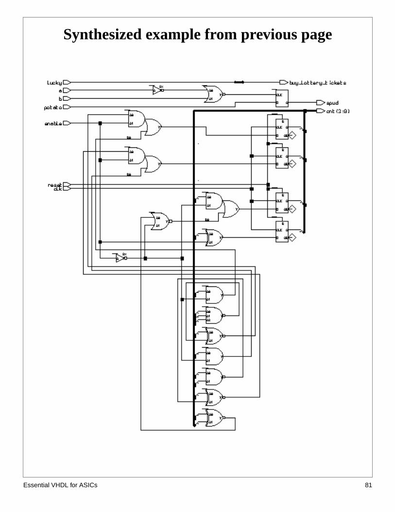
--enabled latchIF (a = ‘1’ AND b = ‘0’) THEN spud <= potato;END IF;
--a very simple “gate”IF (lucky = ‘1’) THEN buy_lottery_tickets <= ‘1’;ELSE buy_lottery_tickets <= ‘0’;END IF;
--a edge triggered 4-bit counter with enable--and asynchronous resetIF (reset = ‘1’) THEN cnt <= “0000”; ELSIF (clk’EVENT AND clk = ‘1’) THEN IF enable = ‘1’ THEN cnt <= cnt + 1; END IF ;END IF;
A Hint: Only IF..... needsEND IF
sential VHDL for ASICs 80
Es
Synthesized example from previous page
sential VHDL for ASICs 81
Es
one
IF Implies Priority
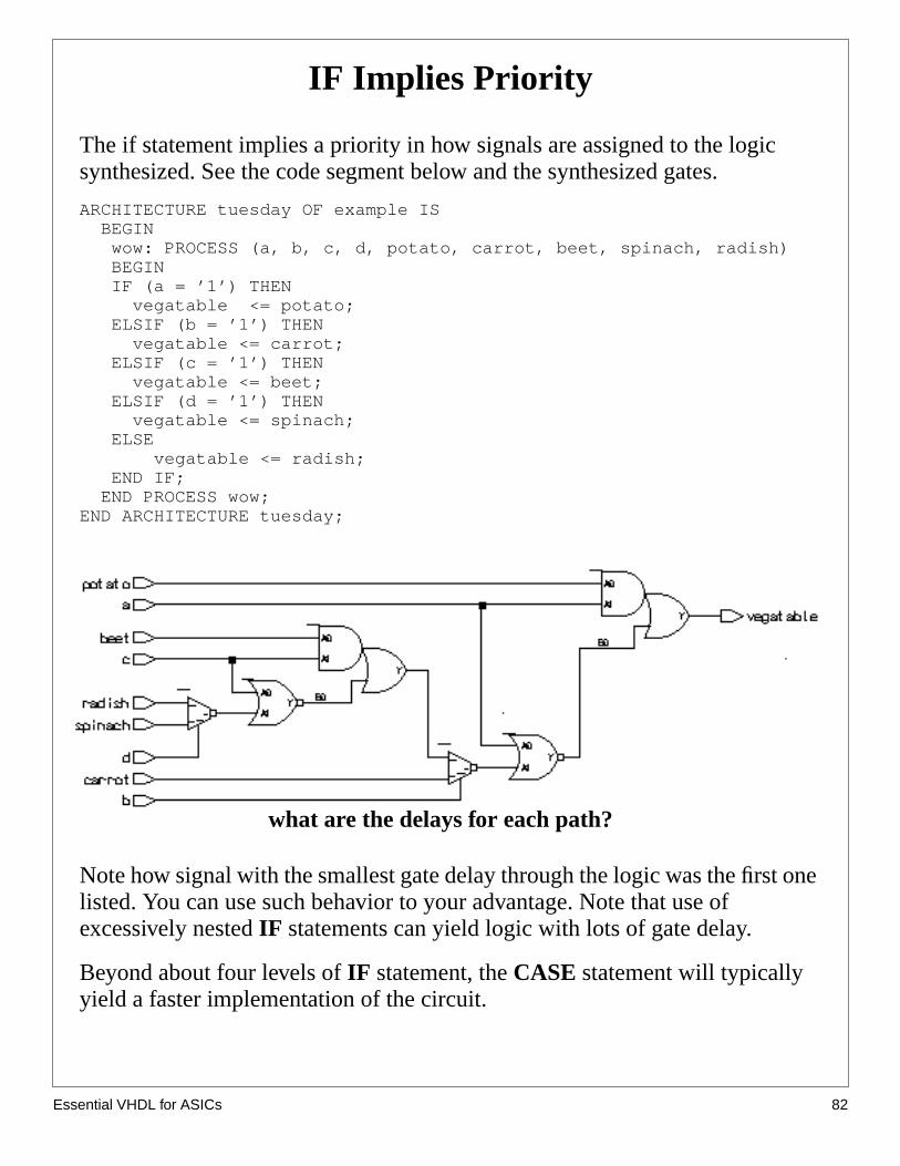
The if statement implies a priority in how signals are assigned to the logicsynthesized. See the code segment below and the synthesized gates.
ARCHITECTURE tuesday OF example IS BEGIN wow: PROCESS (a, b, c, d, potato, carrot, beet, spinach, radish) BEGIN IF (a = ’1’) THEN vegatable <= potato; ELSIF (b = ’1’) THEN vegatable <= carrot; ELSIF (c = ’1’) THEN vegatable <= beet; ELSIF (d = ’1’) THEN vegatable <= spinach; ELSE vegatable <= radish; END IF; END PROCESS wow;END ARCHITECTURE tuesday;
Note how signal with the smallest gate delay through the logic was the firstlisted. You can use such behavior to your advantage. Note that use ofexcessively nestedIF statements can yield logic with lots of gate delay.
Beyond about four levels ofIF statement, theCASE statement will typicallyyield a faster implementation of the circuit.
what are the delays for each path?
sential VHDL for ASICs 82
Es
er ofis
Area and delay of nested IF statement
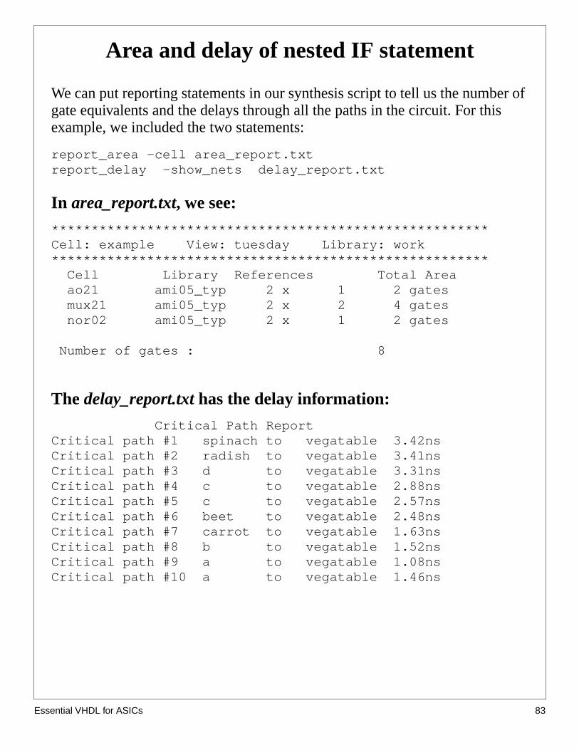
We can put reporting statements in our synthesis script to tell us the numbgate equivalents and the delays through all the paths in the circuit. For thexample, we included the two statements:
report_area -cell area_report.txtreport_delay -show_nets delay_report.txt
In area_report.txt, we see:
*******************************************************Cell: example View: tuesday Library: work******************************************************* Cell Library References Total Area ao21 ami05_typ 2 x 1 2 gates mux21 ami05_typ 2 x 2 4 gates nor02 ami05_typ 2 x 1 2 gates
Number of gates : 8
The delay_report.txt has the delay information:
Critical Path ReportCritical path #1 spinach to vegatable 3.42nsCritical path #2 radish to vegatable 3.41nsCritical path #3 d to vegatable 3.31nsCritical path #4 c to vegatable 2.88nsCritical path #5 c to vegatable 2.57nsCritical path #6 beet to vegatable 2.48nsCritical path #7 carrot to vegatable 1.63nsCritical path #8 b to vegatable 1.52nsCritical path #9 a to vegatable 1.08nsCritical path #10 a to vegatable 1.46ns
sential VHDL for ASICs 83
Es
s ack is
ned
is
If implies priority (cont.)
The order in which the IF’s conditional statement are evaluated also makedifference in how the outputs value is assigned. For example, the first chefor (a = ‘1’). If this statement evaluates true, the output vegetable is assig“potato” for any input combination where a= ‘1’.
If the first check fails, the possibilities narrow. If the second check (b= ‘1’)true, then any combination where a is ‘0’ an b is ‘1’ will assign carrot tovegetable.
If all prior checks fail, an ending ELSE catches all other possibilities.
sential VHDL for ASICs 84
Es
Relational Operators
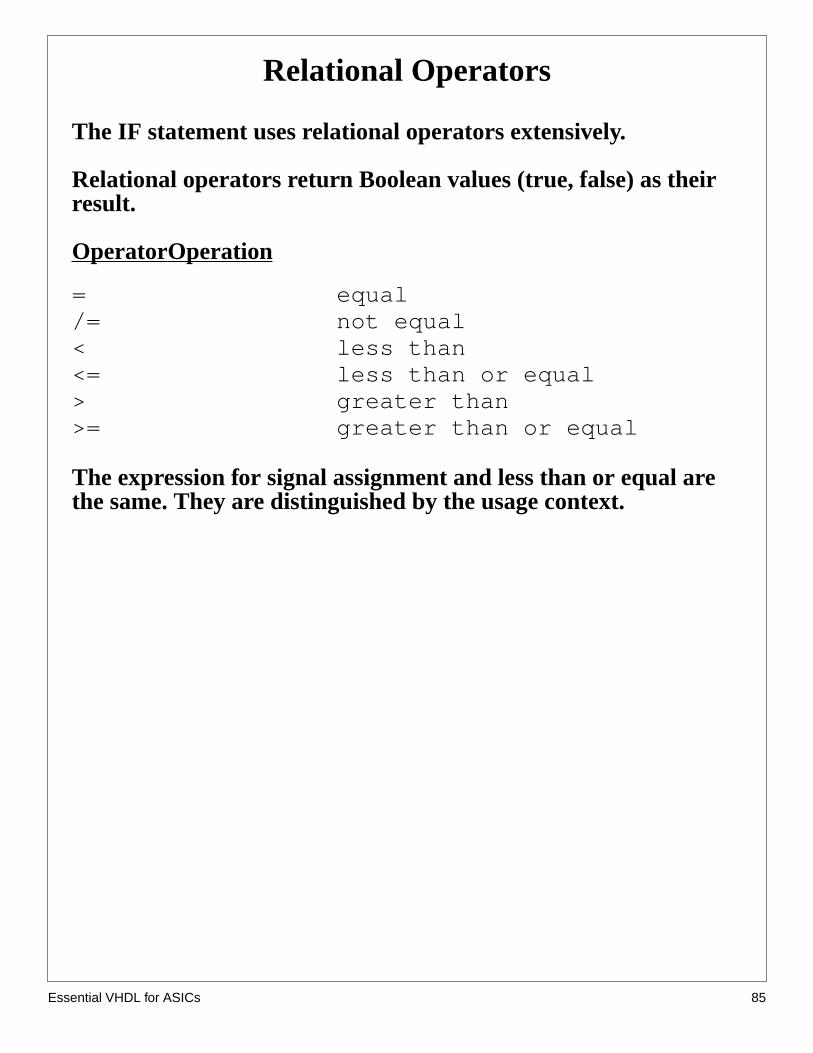
The IF statement uses relational operators extensively.
Relational operators return Boolean values (true, false) as theirresult.
OperatorOperation
= equal/= not equal< less than<= less than or equal> greater than>= greater than or equal
The expression for signal assignment and less than or equal arethe same. They are distinguished by the usage context.
sential VHDL for ASICs 85
Es
CASE Statement
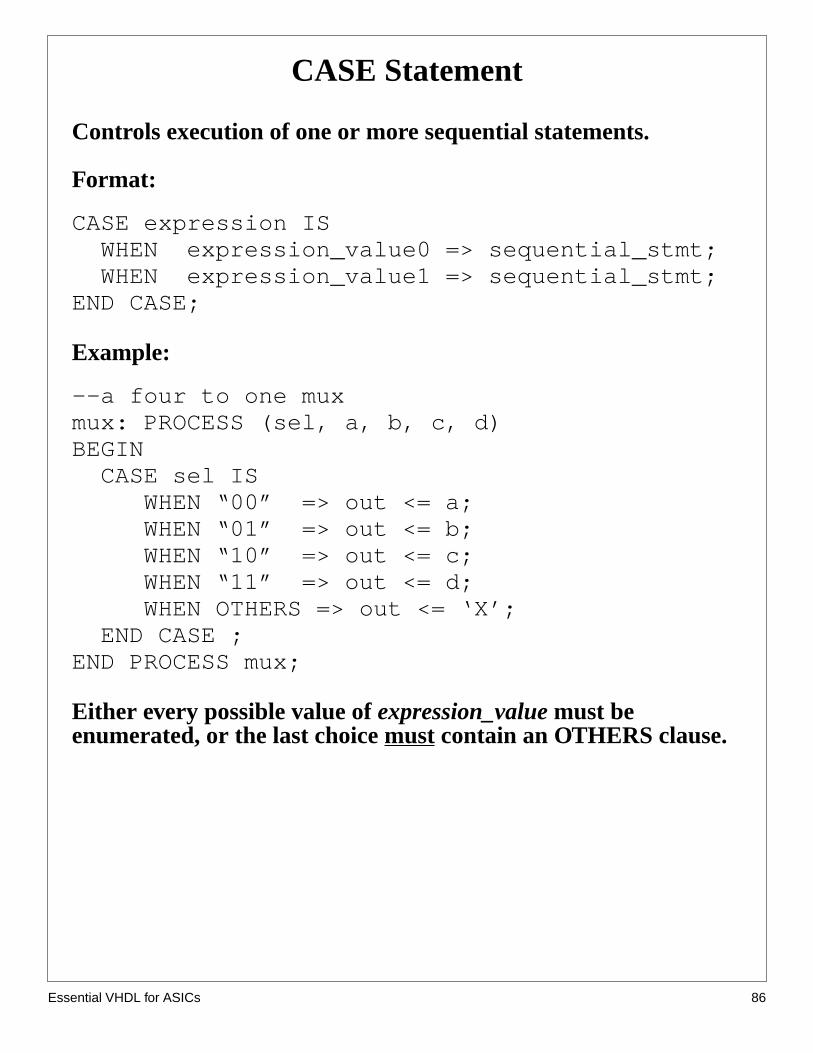
Controls execution of one or more sequential statements.
Format:
CASE expression IS WHEN expression_value0 => sequential_stmt; WHEN expression_value1 => sequential_stmt;END CASE;
Example:
--a four to one muxmux: PROCESS (sel, a, b, c, d)BEGIN CASE sel IS WHEN “00” => out <= a; WHEN “01” => out <= b; WHEN “10” => out <= c; WHEN “11” => out <= d; WHEN OTHERS => out <= ‘X’; END CASE ;END PROCESS mux;
Either every possible value ofexpression_value must beenumerated, or the last choicemust contain an OTHERS clause.
sential VHDL for ASICs 86

Es
d to
ut
l
CASE Implies equal priority
TheCASE statement implies equal priority to how the signals are assignethe circuit. For example, we will repeat the previousIF example usingCASE.To do so, we combine the selection signals into a bus and make the outpselection on the bus value as shown below.
ARCHITECTURE tuesday OF example IS SIGNAL select_bus : STD_LOGIC_VECTOR(3 DOWNTO 0); BEGIN select_bus <= (d & c & b & a); --make the select bus wow: PROCESS (select_bus, potato, carrot, beet, spinach, radish) BEGIN CASE select_bus IS WHEN "0001" => vegatable <= potato; WHEN "0010" => vegatable <= carrot; WHEN "0100" => vegatable <= beet; WHEN "1000" => vegatable <= radish; WHEN OTHERS => vegatable <= spinach; END CASE; END PROCESS wow;END ARCHITECTURE tuesday;
With the exception of spinach, the number of gate delays from each signainput to output is four. The gate delays in theIF example varied from 1 to 8gate delays. However, this function for CASE could be coded better.
sential VHDL for ASICs 87
Es
codeee
Itsd
Using CASE more effectively
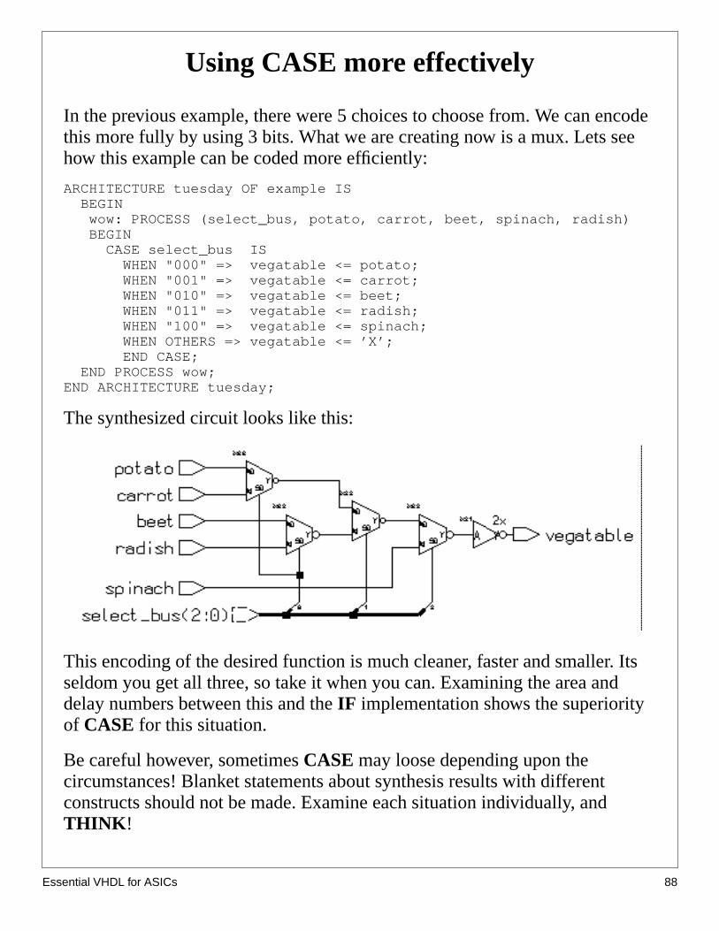
In the previous example, there were 5 choices to choose from. We can enthis more fully by using 3 bits. What we are creating now is a mux. Lets show this example can be coded more efficiently:
ARCHITECTURE tuesday OF example IS BEGIN wow: PROCESS (select_bus, potato, carrot, beet, spinach, radish) BEGIN CASE select_bus IS WHEN "000" => vegatable <= potato; WHEN "001" => vegatable <= carrot; WHEN "010" => vegatable <= beet; WHEN "011" => vegatable <= radish; WHEN "100" => vegatable <= spinach; WHEN OTHERS => vegatable <= ’X’; END CASE; END PROCESS wow;END ARCHITECTURE tuesday;
The synthesized circuit looks like this:
This encoding of the desired function is much cleaner, faster and smaller.seldom you get all three, so take it when you can. Examining the area andelay numbers between this and theIF implementation shows the superiorityof CASE for this situation.
Be careful however, sometimesCASE may loose depending upon thecircumstances! Blanket statements about synthesis results with differentconstructs should not be made. Examine each situation individually, andTHINK !
sential VHDL for ASICs 88
Es
Delay and area report: efficient CASE example
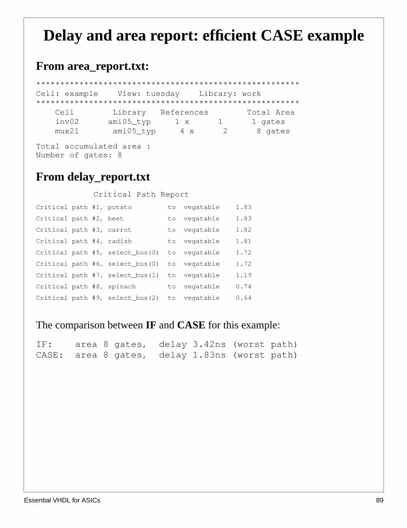
From area_report.txt:*******************************************************Cell: example View: tuesday Library: work******************************************************* Cell Library References Total Area inv02 ami05_typ 1 x 1 1 gates mux21 ami05_typ 4 x 2 8 gates
Total accumulated area :Number of gates: 8
From delay_report.txt Critical Path Report
Critical path #1, potato to vegatable 1.83
Critical path #2, beet to vegatable 1.83
Critical path #3, carrot to vegatable 1.82
Critical path #4, radish to vegatable 1.81
Critical path #5, select_bus(0) to vegatable 1.72
Critical path #6, select_bus(0) to vegatable 1.72
Critical path #7, select_bus(1) to vegatable 1.19
Critical path #8, spinach to vegatable 0.74
Critical path #9, select_bus(2) to vegatable 0.64
The comparison betweenIF andCASE for this example:
IF: area 8 gates, delay 3.42ns (worst path)CASE: area 8 gates, delay 1.83ns (worst path)
sential VHDL for ASICs 89
Es
’r the
is
bewn
s
utt
utic.
a
hat
Use of OTHERS in MUXes
In the former example, theOTHERS clause assigned the output value of ‘Xfor inputs other than those explicitly stated. There are two main reasons fouse of ‘X’.
Simulation and debugging
Remember that we are using the 9 level logic type STD_LOGIC_1164. Thtype specifies that a signal can take on a “real world” set of values;0,1,H,L,Z,X,W,U,-. All these values are included so that we simulate thebehavior or “real” circuits such as resistive pullups and pulldowns, tri-statebuffers and even initialized logic. An example of an uninitialized cell woulda flip flop output just after power is applied. Its output is considered unknoor ‘U’ by the simulator while if its setup or hold time is violated, the flip flop’output becomes unknown or ‘X’ immediately after the clock edge.
If a setup violation occurs during the simulation of a circuit, a flip flop’s outpwill go ‘X’. If the flip flop’s output forms the select input to a mux, what inpusignal will be propagated to the output? In other words, if theselect_bussignalbecomes “0X1”, what input signal value willvegatabletake on. This is knownin polite circles as theX propagation issue.
If we chose another valid input for the OTHERS clause, the error (‘X’ outpfrom a flip flop) in the simulation will not be propagated to downstream logIt will stop or be lost at the mux input because the select_bus value “0X1”maps to a valid input. At the next clock cycle the flip flop may transition tovalid state, the simulation will continue and the error will go unnoticed. Wewould rather have the ‘X’ propagate thorough the logic and “blow up” thesimulation so we can catch the error.
The code below is valid and wouldnot propagate the ‘X’ condition. It alsorepresents an “overly specified” circuit. It is overly specified in the sense tsurely all the possible values ofselect_bus should not map topotato. Givingsome degree of freedom actually produces a smaller gate realization.
sential VHDL for ASICs 90
Es
.
‘X’
Use of OTHERS (cont.)
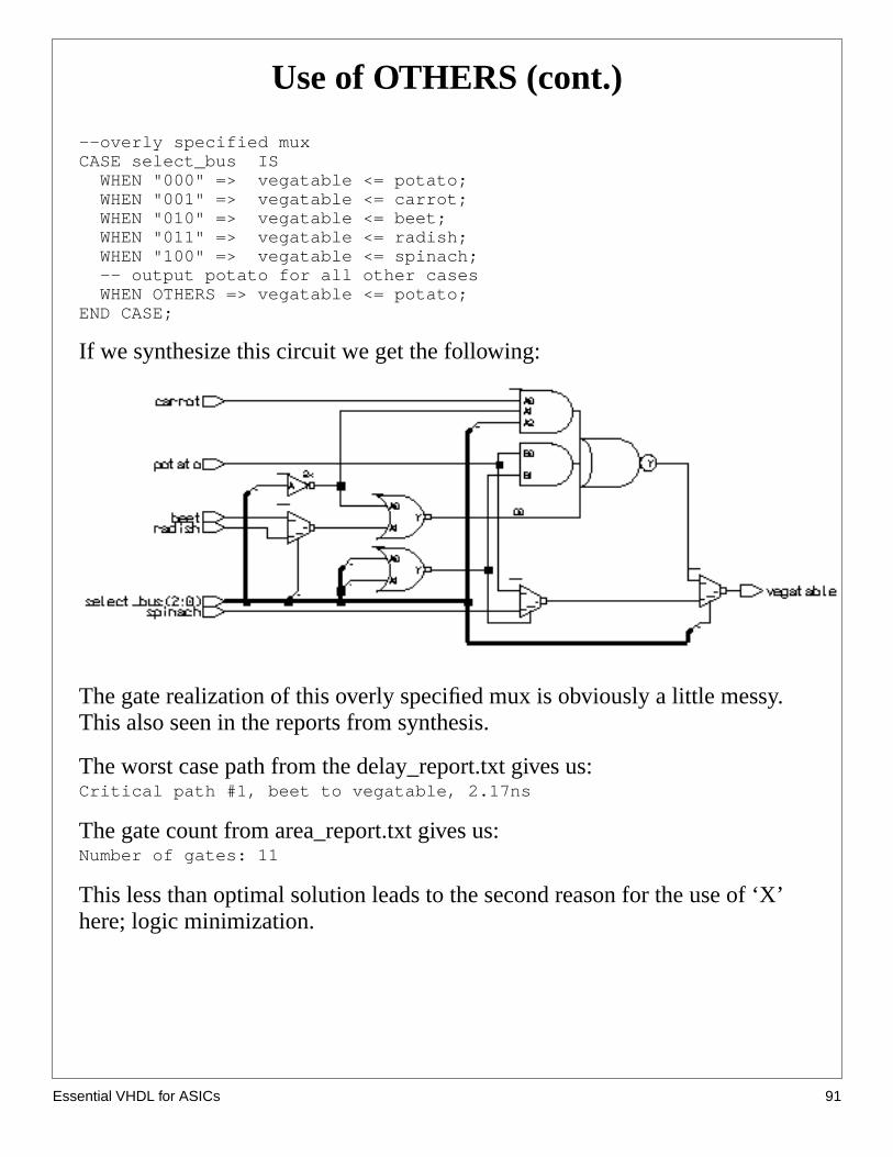
--overly specified muxCASE select_bus IS WHEN "000" => vegatable <= potato; WHEN "001" => vegatable <= carrot; WHEN "010" => vegatable <= beet; WHEN "011" => vegatable <= radish; WHEN "100" => vegatable <= spinach; -- output potato for all other cases WHEN OTHERS => vegatable <= potato;END CASE;
If we synthesize this circuit we get the following:
The gate realization of this overly specified mux is obviously a little messyThis also seen in the reports from synthesis.
The worst case path from the delay_report.txt gives us:Critical path #1, beet to vegatable, 2.17ns
The gate count from area_report.txt gives us:Number of gates: 11
This less than optimal solution leads to the second reason for the use of here; logic minimization.
sential VHDL for ASICs 91
Es
utput‘X’
theed in
lue, ‘-
butbee
Use of OTHERS (cont.)
Logic minimization
The synthesis tool must choose from a library of cells to create the circuitdescribed by the HDL code. In the case of using the statement:
WHEN OTHERS => vegatable <= ’X’;
What does the synthesis tool do? There is no gate that can produce a ‘X’ oexcept when malfunctioning. How can it make a set of gates to produce anoutput? The answer is that it doesn’t.
Thesynthesizer treats the ‘X’ in this case as adon’t care. This is just like thedon’t care in a Karnough map. It allow the synthesis to optimize (reduce) gate count if possible. The simulator treats the X as a value to be propagatsimulation if an error happens.
In fact, we can use another value in the mux statement; the don’t care va’. So we could have coded the mux as follows:
--don’t do this!CASE select_bus IS WHEN "000" => vegatable <= potato; WHEN "001" => vegatable <= carrot; WHEN "010" => vegatable <= beet; WHEN "011" => vegatable <= radish; WHEN "100" => vegatable <= spinach; WHEN OTHERS => vegatable <= ’-’;END CASE;
This would allow the same optimizations as the ‘X’ for the OTHERS casethe behavior of the simulation in the case of a ‘-’ being propagated could library and simulator dependent. This wouldNOT be a be a good way to coda mux even though the synthesized circuit is identical to the mux with theOTHERS statement using ‘X’.
sential VHDL for ASICs 92
Es
),
t, the.
Use of OTHERS (conclusion)
By using the statement:
WHEN OTHERS => vegatable <= ’X’;
the synthesizer can create a small, fast circuit that behaves properly.
One basic premise of how we want to code our designs is that we want thesimulation of our code to act exactly as the gate implementation. If a realmux had a metastable (think ‘X’) input, the output would be metastable (Xnot some valid (0 or 1) state.
The proper use of the don’t care operator is found in creating complexcombinatorial logic and in state machine state assignments. In that contexdon’t care operator really shines. We will see some examples of this soon
sential VHDL for ASICs 93
Es
Loops
Sequences of statements that are executed repeatedly.
Types of loops:
• For (most common usage)
• While
• Loop with exit construct (we skip this)
General Format:
[loop_label:]iteration_scheme --FOR, WHILELOOP --sequence_of_statements;END LOOP[loop_label];
sential VHDL for ASICs 94
Es
For Loop
Statements are executed once for each value in the loopparameter’s range
Loop parameter is implicitly declared and may not be modifiedfrom within loop or used outside loop.
Format:
[label:] FOR loop_parameter IN discrete_rangeLOOP--sequential_statements
END LOOP[label];
Example:
PROCESS (ray_in)BEGIN --connect wires in a two busses label: FOR index IN 0 TO 7 LOOP ray_out(index) <= ray_in(index); END LOOP label;END PROCESS;
sential VHDL for ASICs 95
Es
While Loop
Execution of statements within loop is controlled by Booleancondition.
Condition is evaluated before each repetition of loop.
Format:
WHILE boolean_expressionLOOP--sequential_expressionsEND LOOP;
Example:
p1:PROCESS (ray_in) VARIABLE index : integer := 0;BEGIN from_in_to_out: WHILE index < 8 LOOP ray_out(index) <= ray_in(index); index := index + 1; END LOOP from_in_to_out;END PROCESS p1;
sential VHDL for ASICs 96
Es
Attributes
Attributes specify “extra” information about some aspect of aVHDL model.
There are a number of predefined attributes provide a way toquery arrays, bit, and bit vectors.
Additional attributes may be defined by the user.
Format:
object_name’attribute_designator
The “ ‘ ” is referred to as “tick”.
Example:
ELSIF (clk’EVENT AND clk = ‘1’) THEN
sential VHDL for ASICs 97

Es
Predefined Signal Attributes
signal’EVENT - returns value “TRUE” or “FALSE” if eventoccurred in present delta time period.
signal’ACTIVE - returns value “TRUE” or “FALSE” if activityoccurred in present delta time period.
signal’STABLE - returns a signal value “TRUE” or “FALSE”based on event in (t) time units.
signal’QUIET - returns a signal value “TRUE” or “FALSE”based on activity in (t) time units.
signal’TRANSACTION - returns an event whenever there isactivity on the signal.
signal’DELAYED(t) - returns a signal delayed (t) time units.
signal’LAST_EVENT - returns amount of time since last event.
signal’LAST_ACTIVE - returns amount of time since last activity.
signal’LAST_VALUE - returns value equal to previous value.
sential VHDL for ASICs 98
Es
Using Attributes
Rising clock edge:
clk’EVENT and clk = ‘1’
OR:
NOT clk’STABLE AND clk =’1’
Falling clock edge:
clk’EVENT AND clk = ‘0’
Checking for too short pulse width:
ASSERT (reset’LAST_EVENT >= 3ns) REPORT “reset pulse too short!”;
Checking stability of a signal:
signal’STABLE(10ns)
sential VHDL for ASICs 99
Es
Generic Clause
Generics may be used for readability, maintenance andconfiguration.
They allow a component to be customized by creating aparameter to be passed on to the architecture.
Format:
GENERIC (generic_name:type[:= default_value]);
If default_value is missing, it must be present when thecomponent is instantiated.
Example:
ENTITY half_adder IS GENERIC( tpd_result : delay := 4ns; tpd_carry : delay := 3ns); PORT( x IN : std_logic; y IN : std_logic; z OUT : std_ulogic);END nand_gate;
ARCHITECTURE dataflow OF half_adder BEGIN I result <= x XOR y AFTER tpd_result; carry <= x AND y AFTER tpd_carry; END dataflow;
sential VHDL for ASICs 100
Es
mesial,
inge
igh,
Inferring Storage Elements
In our designs, we usually use flip-flops as our storage elements. Sometiwe use latches, but not often. Latches are smaller in size, but create specoften difficult situations for testing and static timing analysis.
Latches are inferred in VHDL by using the IF statement without its matchELSE. This causes the synthesis to make the logical decision to “hold” thvalue of a signal when not told to do anything else with it.
The inferred latch is a transparent latch. That is, for as long as enable is hthe q output “sees” the d input transparently.
--infer 4-bit wide latchLIBRARY ieee;USE ieee.std_logic_1164.ALL;USE ieee.std_logic_vector_arith.ALL;
ENTITY storage IS PORT ( data_in : IN STD_LOGIC_VECTOR(3 DOWNTO 0); data_out : OUT STD_LOGIC_VECTOR(3 DOWNTO 0); enable : IN STD_LOGIC);END storage;
ARCHITECTURE wed OF storage IS BEGIN infer_latch: PROCESS (enable, data_in) BEGIN IF enable = ‘1’ THEN data_out <= data_in; END IF; --look ma, no else! END PROCESS infer_latch;END ARCHITECTURE wed;
When synthesized, we see the following structure:
sential VHDL for ASICs 101
Es
.ng
s,
:
ey
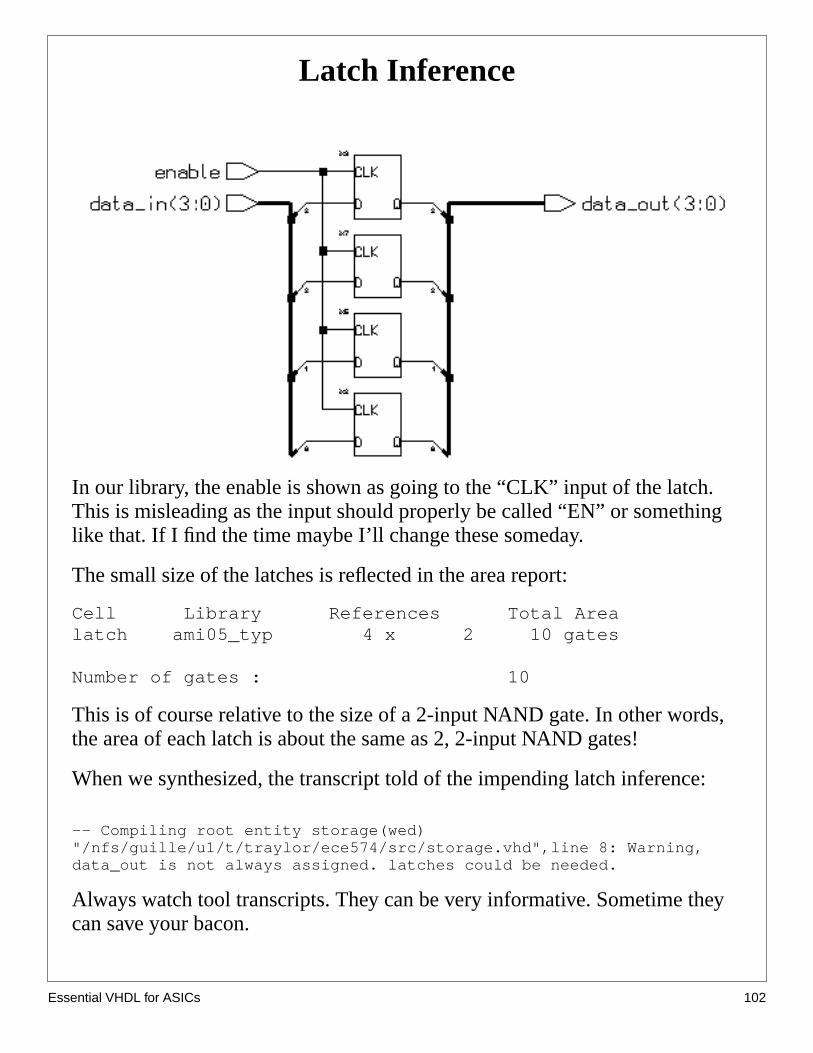
Latch Inference
In our library, the enable is shown as going to the “CLK” input of the latchThis is misleading as the input should properly be called “EN” or somethilike that. If I find the time maybe I’ll change these someday.
The small size of the latches is reflected in the area report:
Cell Library References Total Arealatch ami05_typ 4 x 2 10 gates
Number of gates : 10
This is of course relative to the size of a 2-input NAND gate. In other wordthe area of each latch is about the same as 2, 2-input NAND gates!
When we synthesized, the transcript told of the impending latch inference
-- Compiling root entity storage(wed)"/nfs/guille/u1/t/traylor/ece574/src/storage.vhd",line 8: Warning,data_out is not always assigned. latches could be needed.
Always watch tool transcripts. They can be very informative. Sometime thcan save your bacon.
sential VHDL for ASICs 102
Es
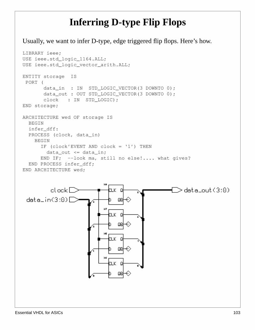
Inferring D-type Flip Flops
Usually, we want to infer D-type, edge triggered flip flops. Here’s how.
LIBRARY ieee;USE ieee.std_logic_1164.ALL;USE ieee.std_logic_vector_arith.ALL;
ENTITY storage IS PORT ( data_in : IN STD_LOGIC_VECTOR(3 DOWNTO 0); data_out : OUT STD_LOGIC_VECTOR(3 DOWNTO 0); clock : IN STD_LOGIC);END storage;
ARCHITECTURE wed OF storage IS BEGIN infer_dff: PROCESS (clock, data_in) BEGIN IF (clock’EVENT AND clock = ‘1’) THEN data_out <= data_in; END IF; --look ma, still no else!.... what gives? END PROCESS infer_dff;END ARCHITECTURE wed;
sential VHDL for ASICs 103
Es
the
uted
t the
old by
Sometime back we stated that IF with ELSE infers a latch. Well... that isusually true. Here is an exception. The line:
IF (clock’EVENT AND clock = ‘1’) THEN
is special to the synthesis tool. The conditional statement for the IF uses attribute which looks for a change in the signalclock(clock’EVENT ). This isANDed with the condition thatclock is now ‘1’ (AND clock = ‘1’ ). Theconditional is looking for a rising edge of the signalclock.
Therefore, if there is a rising edge, the statement under the IF will be execand at no other time. So when the clock rises, data_out will get the valuepresent at data_in. Since a D flip-flop is the only cell that can satisfy thiscondition and can hold the value once it is acquired it is used to implemencircuit. The conditional(clock’EVENT AND clock = ‘1’) really forms therecipe for a D-type rising edge flip flop.
A ELSE clause could be added to the IF statement that explicitly tells thevalue to be held. This is not at all harmful, but is redundant and is ignoredthe synthesis tool. An example of this is shown below:
infer_dff: PROCESS (clock, data_in) BEGIN IF (clock’EVENT AND clock = ‘1’) THEN data_out <= data_in; --get new value ELSE data_out <= data_out; --hold old value...UNNECESSARY END IF; END PROCESS infer_dff;
sential VHDL for ASICs 104
Es
theith
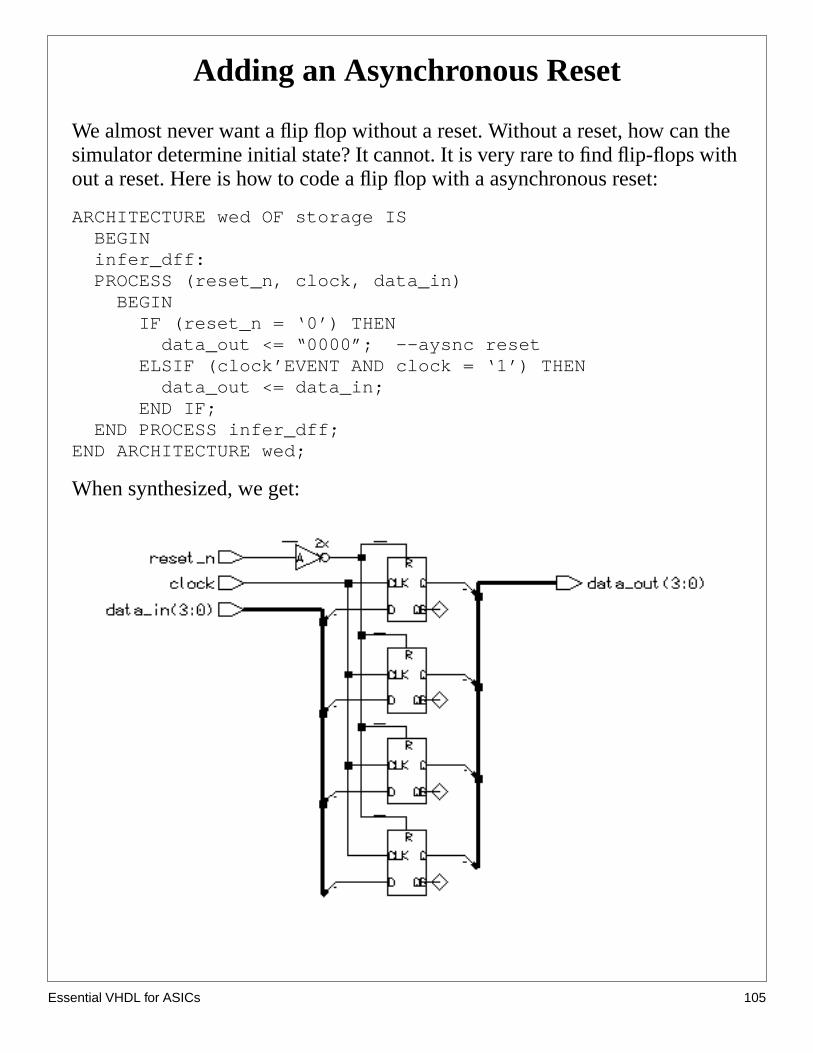
Adding an Asynchronous Reset
We almost never want a flip flop without a reset. Without a reset, how cansimulator determine initial state? It cannot. It is very rare to find flip-flops wout a reset. Here is how to code a flip flop with a asynchronous reset:
ARCHITECTURE wed OF storage IS BEGIN infer_dff: PROCESS (reset_n, clock, data_in) BEGIN IF (reset_n = ‘0’) THEN data_out <= “0000”; --aysnc reset ELSIF (clock’EVENT AND clock = ‘1’) THEN data_out <= data_in; END IF; END PROCESS infer_dff;END ARCHITECTURE wed;
When synthesized, we get:
sential VHDL for ASICs 105

Es
r)
How big is a flip flop/latch?
From the area_report.txt file we see:
Cell Library References Total Areadffr ami05_typ 4 x 6 24 gatesinv02 ami05_typ 1 x 1 1 gatesNumber of gates : 24
This looks a little fishy. 24 + 1 = 24? At any rate, (assuming round off errothe flip flops are roughly 6 gates a piece.
So to summarize the relative sizes of latches and flip flops:CASE CELL SIZElatch no reset latch 2 gateslatch with reset latchr 3 gatesflip flop with no reset dff 5 gatesflip flop with reset dffr 6 gates
These numbers are valid only for our library. Other libraries will vary.However, the relative sizes are consistent with most any CMOS library.
sential VHDL for ASICs 106