concurrent statements -...
TRANSCRIPT

Es
Concurrent Statements - GENERATE
VHDL provides the GENERATE statement to create well-patterned structures easily.
Any VHDL concurrent statement can be included in aGENERATE statement, including another GENERATEstatement.
Two ways to apply
• FOR scheme
• IF scheme
FOR Scheme Format:
label : FOR identifier IN range GENERATE concurrent_statements;END GENERATE [label];
sential VHDL for ASICs 61

Es
Generate Statement - FOR scheme
ARCHITECTURE test OF test ISCOMPONENT and02 PORT( a0 : IN std_logic; a1 : IN std_logic; y : OUT std_logic); END COMPONENT and02;
BEGIN G1 : FOR n IN (length-1) DOWNTO 0 GENERATE and_gate:and02 PORT MAP( a0 => sig1(n), a1 => sig2(n), y => z(n)); END GENERATE G1;END test;
With the FOR scheme
• All objects created are similar.
• The GENERATE parameter must be discrete and is undefinedoutside the GENERATE statement.
• Loop cannot be terminated early
Note: This structure could have been created by:
sig3 <= sig1 AND sig2;
provided the AND operator was overloaded for vector operations.
A BZ
A BZ
A BZ
A BZ
A BZ
A BZ
A BZ
A BZ
sig1(7:0)
sig2(7:0)
sig3(7:0)
sential VHDL for ASICs 62

Es
Generate Statement - IF scheme
Allows for conditional creation of components.
Can’t use ELSE or ELSIF clauses.
IF Scheme Format:
label : IF (boolean_expression) GENERATE concurrent_statements;END GENERATE [label];
The next slide will show how we can use both FOR and IFschemes.
sential VHDL for ASICs 63

Es
Use of GENERATE - An example
Suppose we want to build an 8-bit shift register.
Suppose furthermore that we had previously defined the followingcomponents:
ENTITY dff IS PORT(d, clk, en : IN std_logic; q, qn : OUT std_logic); END ENTITY dff;
ENTITY mux21 IS PORT(a, b, sel : IN std_logic; z : OUT std_logic); END ENTITY mux21;
D
CLK
QE
D
CLK
QE
D
CLK
QE
D
CLK
QE
shiftscan_in
clkenable
d(0) d(1) d(2)
q(0) q(1) q(2)
d(7)
q(7)
sential VHDL for ASICs 64

Es
Using GENERATE
From the block diagram we know what the entity should look like.
ENTITY sr8 IS PORT( din : IN std_logic_vector(7 DOWNTO 0); sel : IN std_logic; shift : IN std_logic; scan_in : IN std_logic; clk : IN sed_logic; enable : IN std_logic; dout : OUT std_logic_vector(7 DOWNTO 0));
Within the architecture statement we have to declare thecomponents within the declaration region before using them. Thisis done as follows:
ARCHITECTURE example OF sr8 IS--declare components in declaration areaCOMPONENT dff IS PORT(d, clk, en : IN std_logic; q, qn : OUT std_logic); END COMPONENT;COMPONENT mux21 IS PORT(a, b, sel : IN std_logic; z : OUT std_logic); END COMPONENT;
Component declarations look just like entity clauses, exceptCOMPONENT replaces ENTITY. Use cut and paste to preventmistakes!
sential VHDL for ASICs 65

Es
Using Generate
After the component declarations, we declare the internal signal.
SIGNAL mux_out : std_logic_vector(7 DOWNTO 0);
With loop and generate statements, instantiate muxes and dff’s.
BEGIN OUTERLOOP: FOR i IN 0 TO 7 GENERATE INNERLOOP1: IF (i = 0) GENERATE MUX: mux21 PORT MAP(a => d(i), b => scan_in, z => mux_out(i)); FLOP: dff PORT MAP(d => mux_out(i), clk => clk, en => enable, q => dout(i)); --qn not listed END GENERATE INNERLOOP1; INNERLOOP2: IF (i > 0) GENERATE MUX: mux21 PORT MAP(a => d(i), b => dout(i-1), z => mux_out(i)); FLOP: dff PORT MAP(d => mux_out(i), clk => clk, en => enable, q => dout(i), qn => OPEN); --qn listed as OPEN END GENERATE INNERLOOP2; END GENERATE OUTERLOOP;END example;
sential VHDL for ASICs 66

Es
e
Concurrent Statements - ASSERT
The assertion statement checks a condition and reports a messagwith a severity level if the condition isnot true.
Format:
ASSERT condition;
ASSERT condition REPORT “message”
ASSERT condition SEVERITY level;
ASSERT condition REPORT “message” SEVERITYlevel;
Example:
ASSERT signal_input = ‘1’ REPORT “Input signal_input is not 1” SEVERITY WARNING;
Severity levels are:
• Note - general information
• Warning - undesirable condition
• Error - task completed, result wrong
• Failure - task not completed
Simulators stop when the severity level matches or exceeds thespecified severity level.
Simulators generally default to a severity level of “failure”
sential VHDL for ASICs 67

Es
Assert Statements
Assert statements may appear within:
• concurrent statement areas
• sequential statement areas
• statement area of entity declaration
Example:
ENTITY rs_flip_flop IS PORT(r, s : IN std_logic; q, qn : OUT std_logic);END rs_flip_flop;
ARCHITECTURE behav OF rs_flip_flop ISBEGIN ASSERT NOT (r = ‘1’ AND s = ‘1’) REPORT “race condition!” SEVERITY FAILURE; * * *END behav;
Remember, the ASSERT statement triggers when the specifiedcondition is false.
sential VHDL for ASICs 68

Es
e
Concurrent Statements - Process Statement
The PROCESS statement encloses a set ofsequentially executedstatements. Statements within the process are executed in theorder they are written. However, when viewed from the “outside”from the “outside”, a process is a single concurrent statement.
Format:
label:PROCESS (sensitivity_list) IS --declarative statements BEGIN -- --sequential activity statements --only sequential statements go in here -- END PROCESS [label];
Example:
ARCHITECTURE example OF nand_gate IS BEGIN nand_gate: PROCESS (a,b) BEGIN IF a = ‘1’ AND b = ‘1’ THEN z <= ‘0’; ELSE z <= ‘1’; END IF; END PROCESS nand_gate;
Why use a process? Some behavior is easier and more natural todescribe in a sequential manner. The next state decoder in a statmachine is an example.
sential VHDL for ASICs 69

Es
Process Sensitivity List
The processsensitivity list lists the signals that will cause theprocess statement to be executed.
Any transition on anyof the signals in the signal sensitivity list willcause the process to execute.
Example:
ARCHITECTURE example OF nand_gate IS BEGIN bozo: PROCESS (a,b) -- wake up process if a and/or b changes BEGIN IF a = ‘1’ AND b = ‘1’ THEN z <= ‘0’; ELSE z <= ‘1’; END IF; END PROCESS bozo;END example;
Signals to put in the sensitivity list:
• Signals on the right hand side of assignment statements.
• Signals used in conditional expressions
What happens if a signal is left out of the sensitivity list?What does the synthesis tool do with the sensitivity list?
Avoid problems with sensitivity list omissions by compiling with “sythesischeck” on. Like this:
vcom -93 -check_synthesis test.vhd
sential VHDL for ASICs 70

Es
t be notal
oidea
its
lay.
y has is
iredwill
What about Delay?
Note that so far we haven’t mentioned delay. Why not?
Both propagation delay and wiring delay is a real-world problem that museventually dealt with. However, at the model creation stage, it is helpful tohave to consider delay. Instead, the emphasis is to create correct functionbehavior.
However, this does not mean the designer can go about designing with nconcern about delay. When writing HDL code, you must have a very goodwhat the structure you are creating will look like in a schematic sense.Otherwise, the synthesized circuit may have excessive delays, preventingoperation at the desired speed.
VHDL does have statements for representing several different kinds of deHowever, when describing a circuit to be synthesized, we never use thembecause the synthesis tool ignores them on purpose.
The aspect of delay is added to a synthesized netlist after the functionalitbeen proven correct. When real delays are inserted into your design (thisdone automatically) often a whole world of problems crop up.
The basic idea is to make a model work, and then make it work at the desspeed. Only experience will help you determine how fast your HDL code eventually run.
sential VHDL for ASICs 71

Es
Delay Types
VHDL signal assignment statements prescribe an amount of timethat must transpire before a signal assumes its new value.
This prescribed delay can be in one of three forms:
• Transport:propagation delay only
• Inertial:minimum input pulse width and propagation delay
• Delta:the default if no delay time is explicitly specified
Signal assignment is actually ascheduling for a future value to beplaced on the signal.
Signals maintain their original value until the time for thescheduled update to occur.
Any signal assignment will incur a delay of one of the three typesabove.
delayinput output
sential VHDL for ASICs 72

Es
Delay Types - Transport
Delay must be explicitly specified by the user by the keywordTRANSPORT.
The signal will assume the new value after specified delay.
Example:
output <= TRANSPORT buffer(input) AFTER 10ns;
Transport delay is like a infinite bandwidth transmission line.
input
output
0 5 10 15 20 25 30 35 40 45
sential VHDL for ASICs 73

Es
Delay Types - Inertial
Inertial delay is the default in VHDL statements which containthe “AFTER” clause.
Inertial delay provides for specification of input pulse width, i.e.‘inertia’ of output, and propagation delay.
Format:
target <= [REJECT time_expr] INERTIAL waveformAFTER time
Example (most common):
output <= buffer(input) AFTER 10ns;
When not used, the REJECT clause defaults to the value of theAFTER clause.
Inertial delay acts like a real gate. It “eats” pulses narrower inwidth than the propagation delay.
input
output
0 5 10 15 20 25 30 35 40 45
sential VHDL for ASICs 74

Es
ter
Delay Types - Inertial
Example of gate with “inertia” smaller than propagation delay:
This shows a buffer that has a prop delay of 10ns, but passes pulses greathan 5ns.
output <= REJECT 5ns INERTIAL buffer(input)AFTER 10ns;
REJECT can be used only with the keyword INERTIAL.
input
output
0 5 10 15 20 25 30 35 40 45
sential VHDL for ASICs 75

Es
n
Delay Types - Delta Delay
Delta delay is the signal assignment propagation delay if none isexplicitly prescribed.
A delta time is an infinitesimal, but quantized unit of time.
An infinite number of delta times equalszero simulator time.
The delta delay mechanism provides a minimum delay so that thesimulation cycle can operate correctly when no delays are statedexplicitly. That is:
• all active processes to execute in the same simulation cycle
• each active process will suspend at somewait statement
• when all processes are suspended, simulation is advanced theminimum time step necessary so that some signals can take otheir new values
• processes then determine if the new signal values satisfy theconditions to proceed again from the wait condition
sential VHDL for ASICs 76

Es
Sequential Operations
Statements within processes are executed in the order in whichthey are written.
The sequential statements we will look at are:
• Variable Assignment
• Signal Assignment*
• If Statement
• Case Statement
• Loops
• Next Statement
• Exit Statement
• Return Statement
• Null Statement
• Procedure Call
• Assertion Statement*
*Have both a sequential and concurrent form.
sential VHDL for ASICs 77

Es
Variable Declaration and Assignment
Variables can be used only within sequential areas.
Format:
VARIABLE var_name : type [:= initial_value];
Example:
VARIABLE spam : std_logic := ‘0’;
ARCHITECTURE example OF funny_gate ISSIGNAL c : STD_LOGIC; BEGIN funny: PROCESS (a,b,c) VARIABLE temp : std_logic; BEGIN temp := a AND b; z <= temp OR c; END PROCESS funny; END ARCHITECTURE example;
Variables assume value instantly.
Variables simulate more quickly since they have no timedimension.
Remember, variables and signals have different assignmentoperators:
a <= new_value; --signal assignmenta := new_value; --variable assignment
sential VHDL for ASICs 78

Es
Sequential Operations - IF Statement
Provides conditional control of sequential statements.
Condition in statement must evaluate to a Boolean value.
Statements execute if boolean evaluates to TRUE.
Formats:
IF condition THEN --simple IF (latch)-- sequential statementsEND IF;
IF condition THEN --IF-ELSE-- sequential statementsELSE-- sequential statementsEND IF;
IF condition THEN --IF-ELSIF-ELSE-- sequential statementsELSIF condition THEN-- sequential statementsELSE-- sequential statementsEND IF;
sential VHDL for ASICs 79
Es
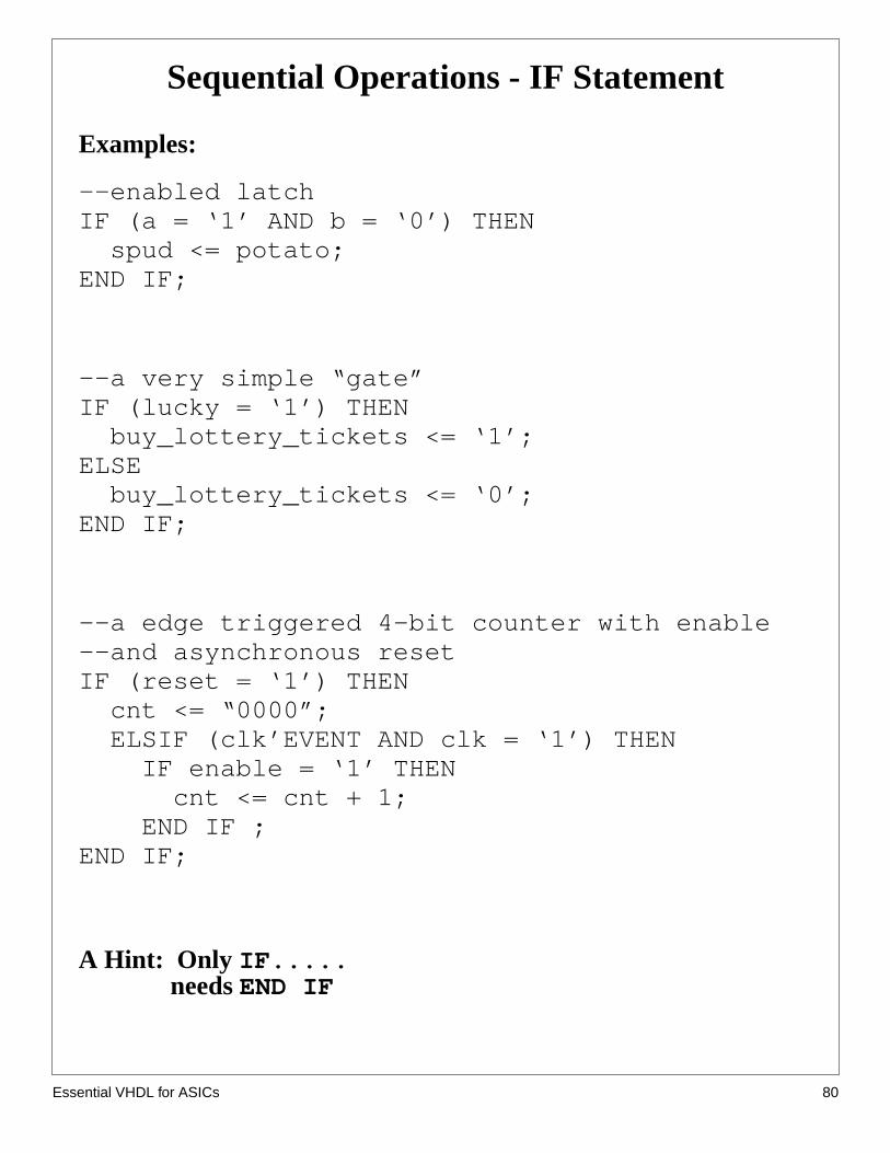
Sequential Operations - IF Statement
Examples:
--enabled latchIF (a = ‘1’ AND b = ‘0’) THEN spud <= potato;END IF;
--a very simple “gate”IF (lucky = ‘1’) THEN buy_lottery_tickets <= ‘1’;ELSE buy_lottery_tickets <= ‘0’;END IF;
--a edge triggered 4-bit counter with enable--and asynchronous resetIF (reset = ‘1’) THEN cnt <= “0000”; ELSIF (clk’EVENT AND clk = ‘1’) THEN IF enable = ‘1’ THEN cnt <= cnt + 1; END IF ;END IF;
A Hint: Only IF..... needsEND IF
sential VHDL for ASICs 80

Es
Synthesized example from previous page
sential VHDL for ASICs 81

Es
one
IF Implies Priority
The if statement implies a priority in how signals are assigned to the logicsynthesized. See the code segment below and the synthesized gates.
ARCHITECTURE tuesday OF example IS BEGIN wow: PROCESS (a, b, c, d, potato, carrot, beet, spinach, radish) BEGIN IF (a = ’1’) THEN vegatable <= potato; ELSIF (b = ’1’) THEN vegatable <= carrot; ELSIF (c = ’1’) THEN vegatable <= beet; ELSIF (d = ’1’) THEN vegatable <= spinach; ELSE vegatable <= radish; END IF; END PROCESS wow;END ARCHITECTURE tuesday;
Note how signal with the smallest gate delay through the logic was the firstlisted. You can use such behavior to your advantage. Note that use ofexcessively nestedIF statements can yield logic with lots of gate delay.
Beyond about four levels ofIF statement, theCASE statement will typicallyyield a faster implementation of the circuit.
what are the delays for each path?
sential VHDL for ASICs 82

Es
er ofis
Area and delay of nested IF statement
We can put reporting statements in our synthesis script to tell us the numbgate equivalents and the delays through all the paths in the circuit. For thexample, we included the two statements:
report_area -cell area_report.txtreport_delay -show_nets delay_report.txt
In area_report.txt, we see:
*******************************************************Cell: example View: tuesday Library: work******************************************************* Cell Library References Total Area ao21 ami05_typ 2 x 1 2 gates mux21 ami05_typ 2 x 2 4 gates nor02 ami05_typ 2 x 1 2 gates
Number of gates : 8
The delay_report.txt has the delay information:
Critical Path ReportCritical path #1 spinach to vegatable 3.42nsCritical path #2 radish to vegatable 3.41nsCritical path #3 d to vegatable 3.31nsCritical path #4 c to vegatable 2.88nsCritical path #5 c to vegatable 2.57nsCritical path #6 beet to vegatable 2.48nsCritical path #7 carrot to vegatable 1.63nsCritical path #8 b to vegatable 1.52nsCritical path #9 a to vegatable 1.08nsCritical path #10 a to vegatable 1.46ns
sential VHDL for ASICs 83

Es
s ack is
ned
is
If implies priority (cont.)
The order in which the IF’s conditional statement are evaluated also makedifference in how the outputs value is assigned. For example, the first chefor (a = ‘1’). If this statement evaluates true, the output vegetable is assig“potato” for any input combination where a= ‘1’.
If the first check fails, the possibilities narrow. If the second check (b= ‘1’)true, then any combination where a is ‘0’ an b is ‘1’ will assign carrot tovegetable.
If all prior checks fail, an ending ELSE catches all other possibilities.
sential VHDL for ASICs 84

Es
Relational Operators
The IF statement uses relational operators extensively.
Relational operators return Boolean values (true, false) as theirresult.
OperatorOperation
= equal/= not equal< less than<= less than or equal> greater than>= greater than or equal
The expression for signal assignment and less than or equal arethe same. They are distinguished by the usage context.
sential VHDL for ASICs 85