september 1998 geo-heat center quarterly bulletin
TRANSCRIPT

8/8/2019 September 1998 Geo-Heat Center Quarterly Bulletin
http://slidepdf.com/reader/full/september-1998-geo-heat-center-quarterly-bulletin 1/40
NEW ZEALAND GEOTHERMALWairakei - 40 years
GEO-HEAT CENTER Quarterly Bulletin
Vol. 19, No. 3 September 1998
ISSN 0276
OREGON INSTITUTE OF TECHNOLOGY -KLAMATH FALLS, OREGON 97601-8801
PHONE NO. (541) 885-1750
8/8/2019 September 1998 Geo-Heat Center Quarterly Bulletin
http://slidepdf.com/reader/full/september-1998-geo-heat-center-quarterly-bulletin 2/40
Vol. 19, No. 3 September 1998
GEO-HEAT CENTER QUARTERLY BULLETINISSN 0276-1084
A Quarterly Progress and Development Reporton the Direct Utilization of Geothermal Resources
CONTENTS Page PUBLISHED BY
A BRIEF HISTORY OF THE WAIRAKEI 1 GEO-HEAT CENTERGEOTHERMAL POWER PROJECT Oregon Institute of Technology Ian A. Thain 3201 Campus Drive
Klamath Falls, Oregon 97601GEOTHERMAL RESOURCES IN NEW ZEALAND - AN OVERVIEW 5 All articles for the Bulletin are solicited. If you wish to
Trevor M. Hunt contribute a paper, please contact the editor at the aboveaddress.
DOMESTIC AND COMMERCIAL HEATING 10& BATHING - ROTORUA AREA EDITOR
Ross Anderson John W. LundTypesetting and Layout - Donna GibsonKAWERAU GEOTHERMAL 15 Graphics - Tonya “Toni” BoydDEVELOPMENT: A CASE STUDY
Andy Bloomer WEBSITE http://www.oit.edu/~geoheat
TIMBER DRYING AT KAWERAU 19 FUNDINGJohn W. Scott and John W. Lund The Bulletin is provided compliments of the Geo-Heat
Center. This material was prepared with the support of GEOTHERMAL GREENHOUSES 21 The U. S. Department of Energy (DOE Grant No. DE-AT KAWERAU FG07-90ID 13040). However, any opinions, findings,
Michael Dunstall and Brian Foster conclusions, or recommendations expressed herein arethose of the author(s) and do not necessarily reflect the
DRYING OF FIBROUS CROPS USING 24 the view of DOE.GEOTHERMAL STEAM AND HOT WATER
AT THE TAUPO LUCERNE COMPANY SUBSCRIPTIONSNeil Pirrit and Michael Dunstall The Bulletin is mailed free of charge. Please send your
name and address to the GEO-HEAT CENTER for PRAWN PARK - TAUPO, NEW ZEALAND 29 addition to the mailing list.
John W. Lund and Richard KleinIf you wish to change your Bulletin subscription, please
GEOTHERMAL ORCHIDS 32 complete the form below and return it to the CENTER.Alistair McLachlan
__ I do not wish to continue receiving the Bulletin.
MIRANDA HOT SPRINGS 35 __ I have a change in address. Please include oldDerek Freeston and John W. Lund address label.
GEOTHERMAL PIPELINE 37 Name _________________________________________ Progress and Development Update From the Geothermal Progress Monitor Address _______________________________________
_______________________________ Zip ___________
Country _______________________________________

8/8/2019 September 1998 Geo-Heat Center Quarterly Bulletin
http://slidepdf.com/reader/full/september-1998-geo-heat-center-quarterly-bulletin 3/40
A BRIEF HISTORY OF THE WAIRAKEI GEOTHERMALPOWER PROJECT
Ian A. Thain,President New Zealand Geothermal Association
INTRODUCTIONNovember 15, 1998 marks the 40 th anniversary of the
commissioning of the first generator at Wairakei geothermalpower station, in New Zealand. At that time it was only thesecond geothermal plant in the world to begin commercialoperation and the first to exploit a wet geothermal resource.This paper briefly traces the development and operationalhistory of this pioneering development and in particular theefforts made to keep the plant supplied with steam.
THE LARDARELLO INFLUENCE ON THEDEVELOPMENT
The impetus for the development of Wairakei camein 1947 from severe electricity shortages following two dryyears which restricted hydro generation and a desire by the
Government for the New Zealand electricity supply to beindependent of imported fuel.
During World War II government scientists arrangedfor New Zealand army engineers serving with the British 8 th
Army, in the Italian campaign, to visit, inspect and report onthe Lardarello geothermal power development in Tuscany.Unfortunately when the army engineers got to the plant inJune 1944 it had been totally destroyed.
Figure 1. Destroyed Lardarello No 2 StationTurbine Hall.
In 1948 visits were again made by New Zealand
engineers to Lardarello. This time they found rebuilt powerplants producing over 140MW and the Lardarello No IIIstation (142MW) in an advanced stage of construction.
While observations at Lardarello were important inproviding the New Zealand engineers with an understandingof the overall approach to harnessing geothermal power, thedry steam resource was so different from the wet geothermalresource at Wairakei that its development would have todepend on exploiting technology designed in New Zealand.
GHC BULLETIN, SEPTEMBER 1998
Figure 2. Rebuilt Lardarello No2 Station Turbine
Hall.
Perhaps Lardarello`s most important contribution to theWairakei development was its success and the enthusiasm theItalian engineers displayed for this type of power plant,because there is no doubt that these factors strongly influencedthe New Zealand decision to proceed with a geothermal powerdevelopment at Wairakei.
INVESTIGATION AND PROJECT DEVELOPMENT(1949 to 1958)
In 1949, a project development team was establishedand drilling together with scientific investigations proceeded
rapidly so that by late 1952 steam capable of producing20MW of electric power had been proven by shallow drilling(300m). Prospect of greater output from deeper drilling wasalso confidently predicted and larger drilling rigs wereordered. Important metallurgical research, into the corrosioneffects of the Wairakei geothermal brine, were also completedabout this time and these showed that mild steel could be usedfor the geothermal above ground systems without sufferingany major corrosion effects. . Mishaps during this earlydevelopment period were few, but when they did occur, ithelped if one had a good turn of speed.
The initial project at Wairakei was conceived as acombined power station and a heavy water plant. This was to
be a joint venture between the New Zealand Government andthe United Kingdom Atomic Energy Authority ( UKAEA).Conceptual designs were progressed and in late 1954 fundingwas approved to build a plant capable of producing 47MW of electric power and 6 tonnes per year of heavy water. However,principally because of major cost increases in the cost of theheavy water plant the UKAEA pulled out of the project inJanuary 1956. As contracts for the turbine generators had beenlet in mid-1955 and their fabrication well advanced, it was
1

8/8/2019 September 1998 Geo-Heat Center Quarterly Bulletin
http://slidepdf.com/reader/full/september-1998-geo-heat-center-quarterly-bulletin 4/40
Figure 3. Techniques and safety standards have improved significantly since the early 1950`s but still present isthe pioneering element exemplified by this early Wairakei photograph.
decided to proceed with the existing power plant design andto incorporate two intermediate pressure (IP) 11MW turbinesgenerators in place of the heavy water plant. The Wairakei“A” station project initially was to consisted of two high
pressure(HP)6.5 MW units; two intermediate pressure (IP)11.2 MW units; and three low pressure (LP) condensing11.2MW units giving an installed capacity of 69MW. Theinlet pressure on the LP units was just above atmosphericpressure.
Meanwhile on the steamfield the larger drilling rigshad been very successful in winning more high pressure fluidat the greater depth. A two pressure system was evolved totap the field; high pressure (HP) which produced flashedsteam at the well head of around 13.5 barg (196 psig ) andintermediate pressure IP producing flashed steam at 4.5 barg(65 psig). As a result of the greater output two HP 11 MWunits and an additional LP 11 MW condensing unit wereadded to complete the Wairakei “A” Station (Stage I)development. This enhanced Stage I design also incorporateda pilot hot water flash plant which was sited adjacent to thepower plant building and was fed with separated water fromfive HP wells and two IP wells. The very successful tangentialentry bottom outlet steam separator was developed. (WairakeiSeparator).
Construction of Stage I was not that far advancedwhen proposals for additional generating capacity wereapproved because even more steam than expected had been
2
found. This resulted in the development of the Wairakei “B”Station which consisted of three mixed pressure (MP)condensing 30 MW generating units. The steam supply to theMP units consisted of 3.5 barg (50 psig) at inlet with pass in
steam at slightly above atmospheric pressure (2 psig) to themachines LP cylinder. This brought the total installed capacityof the Wairakei development to 192.6MW.
A further extension of the “B” Station was allowedfor in the design which would have consisted of two more 30MW mixed pressure units.
The Power Station is located adjacent to the WaikatoRiver from which it draws once through water for the directcontact condensers. The centre of steam production isapproximately 3.5 km (2.2 miles) from the power station andsteam is transmitted to the station via three 760mm (30 inch)and five 508mm ( 20 inch) diameter pipelines.
On 15 November 1958 the first set in the “A” Stationwas synchronized to the national grid. The remainingmachines and plant of the “A” and “B” developmentsproceeded at regular intervals, the last machine beingsynchronized to the grid in October 1963.
SETTING THE PLANT TO WORK ANDDEVELOPMENT SHORTFALLS (1958 to 1968)
The setting to work of the power plant causedunexpected draw down and a rapid pressure decline of steamfield output. Secondly, the pilot hot water scheme had to
GHC BULLETIN, SEPTEMBER 1998

8/8/2019 September 1998 Geo-Heat Center Quarterly Bulletin
http://slidepdf.com/reader/full/september-1998-geo-heat-center-quarterly-bulletin 5/40
be abandoned, for whilst it had operated successfully for ashort period, the wells which were connected to it change tobecome dry steam producers and the plant became starved of separated water. At this time no consideration was given toconnecting additional wells to it as it was thought that they inturn would change with time to become dry steam producers.
With the commissioning of the “B” Station 30MWunits it became necessary to drill more production wells tomake up for the rapid drop in well output. Production drillingcontinued through the early and mid 1960`s and the peak power of 173 MW was achieved in 1965, some 19 MW shortof the installed capacity. However, this drilling was endedshortly afterwards when it was realized that the effort wasyielding ever diminishing returns.
From 1958 to 1968 the “at depth” reservoir pressureof the Wairakei field dropped from 58.6 bar g (850 psig) to 40bar g (580 psig). [The reservoir “at depth” pressure beingobtained from a selection of wells measured at a depth of 275m (900ft) below sea level.]
The field management strategy adopted in the late1960`s was to:
• hold mass output from the field at the currentproduction level of around 50 million tonnes peryear;
• to sacrifice HP machine output by progressivelyreducing HP well head pressure in order to maintainfluid flow and thus ensure that the IP, MP, and LPmachines were fully supplied with steam at designpressure;
• to implement measures which would make moreefficient use of the total energy discharged from thefield and improving the reliability of the generatingplant.
PERIOD OF CONSOLIDATION (1969 to 1982 )The use of flashed steam from separated HP
borewater was not abandoned with the demise of the pilot hotwater scheme. The process was instead moved to thesteamfield where double flash units were installed adjacent toHP wells. These units were initially designed to be portable sothat they could be moved in the event of the wells changing tobecome dry producers as had happened with the pilot hotwater scheme. The well head double flash process was verysuccessful and in 1974 the scheme was extended to tripleflashing so as to extract intermediate low pressure, 1.7bar g(25 psig) (ILP) steam by flashing separated IP borewater atsteamfield located central flash plants. A major part of thisproject was the construction of an ILP steam pipe, of 1.22 m(48 inch ) diameter to carry the 1.7 bar g steam to the powerstation. There the ILP steam was passed through pressurereducing valves to reduce the pressure to 0.05 bar g ( 2 psig)to make suitable for passing into the A Station LP machinesand as pass in steam to the B Station MP Machines.
GHC BULLETIN, SEPTEMBER 1998
Over the next few years a policy of connectingpreviously unused wells and piping additional water to theflash plants to maximize the use of the flash plants and thenew ILP steam transmission line was pursued. When Wairakeiwas commissioned only 4.5 percent of the total energy above0 deg C was converted to electrical energy, with theoptimizing of the triple flash system in the late 1970`s thisconversion factor had been increased to over 8.5 percent.
By 1981 the HP had been progressively reduced to
about 7 bar g (100 psig) and the shortfall in IP and LPmachine generation had fallen below what was beinggenerated by the HP machines. Studies showed that a net gainin generation would be achieved by completelydecommissioning the HP system and derating all HP wells toIP conditions.
Derating the HP system was carried out in November1982 and this involved both wellhead and major flash plantmodifications plus the installation of flow balancingcrossovers on the steam transmission lines. This exerciseresulted in the installed capacity of the plant being reduced to157.2 MW (Gross)
The main reactions of the Wairakei reservoir toexploitation up to this point in time had been:
• after an initial very rapid fall, the “at depth” pressureof the field had now become relatively stable, whichindicates that the mass withdrawal from the field wasbeing balanced by a similar amount of naturalrecharge;
• despite the near stabilization of the “at depth”pressure and mass withdrawal the apparent enthalpyof the fluid continued to decrease slowly, reflectedby annual decline in fluid temperature of around 0.5deg. C per year; indication the system was beingslowly mined of its heat by the production process.
• the water level in the reservoir had been drawndown approximately 200m (650 ft)
After decommissioning the HP system it became fieldmanagement policy to once again tap the field in order tosustain full load on the remaining installed plant.
FIELD MANAGEMENT AND STEAM WINNING (1982to 1997 )
In 1983 three additional existing wells, drilled in themid 1960`s for a proposed new power development on thenorth western sector of the field known as the Te Mihi area,were connected into the Wairakei steam transmission systemThis required extending the steam collection system by afurther 3 km ( approx. 2 miles) further from the power station.The output from these three wells were expected to keep theWairakei plant fully loaded until 1987/88. This however didnot materialize due to the resultant increase in pressure drop
3

8/8/2019 September 1998 Geo-Heat Center Quarterly Bulletin
http://slidepdf.com/reader/full/september-1998-geo-heat-center-quarterly-bulletin 6/40
within the extended steam transmission system pushing upproduction wellhead pressures. This caused the output of allproduction wells to decline marginally. As a result the netincrease in steam supply to the station was only 50% of whathad been expected.
In consequence by 1884, Wairakei was once againfacing a steam shortage.
Faced with further steam winning, attention turned tothe utilization of a dry steam reservoir trapped at shallowdepth beneath an impermeable cap in the Te Mihi area of thefield. The presence of a shallow vapor dominated reservoir inthis area was initially inferred from precise gravity changesand from the direct measurement of steam pressures in theexisting Te Mihi wells. This steam resource having formed asa result of the exploitation of the liquid resource and theresultant draw down in the fluid level by approximately 200m.The reduction in reservoir pressure causing boiling of thefluid.
This steam zone was found to have pressures of around 25 bar g (360 psig ). Beneath the steam cap fluid at upto 260 deg. C temperature was found. This liquid being some30 to 40 deg. C hotter than liquid found in the mainproduction area of the field. Given the good productionpotential the first new production well to be drilled atWairakei since 1967 was drilled into this steam cap in 1985.At a depth of only 390 m (1270 ft) excellent dry steamproduction was encountered.
Following the success of this dry steam well effortsover the next three years were devoted to defining the extentand production potential of the Te Mihi vapor reservoir. Themost important parameter was to determine its size and todetermine this a number of exploratory wells were drilled toprobe the perimeter of the resource. From the data obtained itwas estimated that the resource could sustain a production of around 500 tonnes per hour for many years. Based on theseestimates a development plan was prepared.
This development plan entailed drilling a furtherthree 330 mm diameter (13” ) wells and the construction of a1 m diameter (40” ) steam transmission line approximately 2.5km long ( 1.5 miles) to connect the new production area withthe existing Wairakei steam transmission system. This projectwas completed in September 1988. Two of the wellsencountered excellent production from the shallow dry steamresource; however, the third failed to find permeableconditions at the dry steam horizon and this was successfullydeepened into the liquid zone. These new wells provided asteam surplus and were able to keep the plant fully loadeduntil 1994.
However, the dry steam production was not withoutproblems. The gas content of this steam was significantlyhigher than flashed steam. The net result of this increase wasto increase the content of the steam delivered to the powerplant from 0.4 % to just under 1%. The steam driven gasejectors on the four A Station LP machines were inadequateto handle this increase and the condenser vacuum deteriorated,
4
resulting in a decline in output of around 10 to 12%. The BStation plant ejectors whilst able to maintain design vacuumconditions, it was achieved at the expense of an increase inejector steam supply from 27 to 88 tonnes/hour. Theseproblems were overcome by redesigning the ejectors andimproving the cooling efficiency of the ejector inter cooler.
The second problem encountered with the dry steamwells was that they spasmodically discharged significantquantities of sub micron sized particles of quartz. This quartz
generally appears when the wells are being returned to servicefollowing a shutdown. Whilst contained within the steamphase the quartz very effectively removed silica scale depositsfrom within the turbine steam path and the magnetite coatingsfrom the steam lines causing blockage of the turbine casingdrains. However serious damage resulted when the quartzmixes with steam condensate. This mixture cuts out anddestroys condensate drain valves in a matter of days. As thequartz is so fine it is not possible to remove from the systemby normal debris collection methods. This problem is beingpartly overcome by carrying out a sustained vertical dischargeof the well before it is returned to service.
The last major steam winning project to be carriedout at Wairakei entailed tackling the steamline pressure dropproblem which was overcome by constructing a new 1 mdiameter (40”) pipeline from the power station to thesteamfield. This effectively reduced the wellhead pressure onall the production wells causing the output of each to bemarginally increased. This project was completed in 1995.
Ways of making more efficient use of the energywithdrawn from the Wairakei field has always had a highpriority and this was further enhanced in 1996 when thepressure reducing valves which reduce the ILP steam to LPconditions were replaced by a steam turbine which producesapproximately 4 MW of additional output.
This year further wells were drilled to tap the TeMihi dry steam resource and these have been successful inkeeping the plant once again fully loaded
Perhaps the biggest challenge facing Wairakei in thenear future will be the renewal of its resource consents before2001. Up until now Wairakei has operated under “existinguse” consents which were issued in 1968. With the passing of the Resource Management Act in 1991 all “existing use”resource consent holders had until a certain date to seek renewal of their consents in accordance with the requirementsof the new legislation
SUMMARYWairakei has been one of the most reliable generating
facilities within the New Zealand electricity supply system.Since decommissioning the HP plant in 1982 the station hasoperated consistently with an annual load factor of over 90%.Maintaining this output has been achieved by on-going steamwinning initiatives and it is likely that with carefulmanagement of the resource Wairakei will continue to operatewell into the new millennium.
GHC BULLETIN, SEPTEMBER 1998
8/8/2019 September 1998 Geo-Heat Center Quarterly Bulletin
http://slidepdf.com/reader/full/september-1998-geo-heat-center-quarterly-bulletin 7/40
GEOTHERMAL RESOURCES IN NEW ZEALANDAN OVERVIEW
Trevor M. HuntWairakei Research Centre
Institute of Geological & Nuclear Sciences LimitedPrivate Bag 2000
Taupo, New Zealand
TYPES OF GEOTHERMAL SYSTEMSIn many parts of New Zealand, the rocks at shallow
depth (< 1 km) have high porosity and may contain up to 30%(by volume) of water. Usually, the pores and fractures areconnected so that the water in the rock can move in responseto pressure changes. Fractures have high permeability andallow water to move quickly from place to place.
The Resource Management Act (1991) differentiatesbetween geothermal water and cold groundwater on the basisof temperature: water greater than 30 oC is geothermal, thatbelow 30 oC is groundwater. This distinction has no scientificfoundation–it is based solely on the concept that water above
this arbitrary temperature is an energy resource–it is notpossible to clearly separate geothermal water from coldgroundwater on the basis of temperature alone.
New Zealand’s geothermal waters can generally beseparated (but not always), on the basis of their temperature,geological location and chemistry, into two main groups:
• Low-Temperature Waters with temperatures of between about 20 oC (ambient) and about 100 oC,associated with active faults.
• High-Temperature Waters with temperatures greaterthan 100 oC, associated with areas of active
volcanism.
These waters form convective, hydrological systemswithin the upper part of the crust which are driven by the heatsources. In both cases, in their natural state, these are dynamicsystems–the hot water is continually being lost at the surfaceto rivers and being replaced from deeper in the earth.
LOW-TEMPERATURE TECTONIC GEOTHERMALSYSTEMS
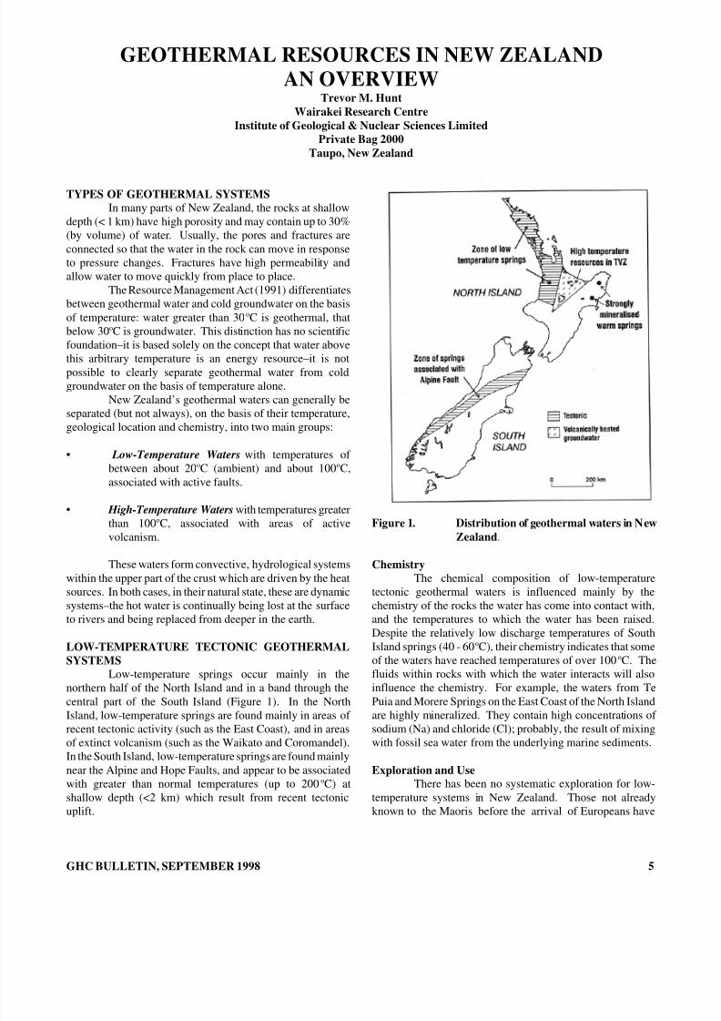
Low-temperature springs occur mainly in thenorthern half of the North Island and in a band through thecentral part of the South Island (Figure 1). In the North
Island, low-temperature springs are found mainly in areas of recent tectonic activity (such as the East Coast), and in areasof extinct volcanism (such as the Waikato and Coromandel).In the South Island, low-temperature springs are found mainlynear the Alpine and Hope Faults, and appear to be associatedwith greater than normal temperatures (up to 200 oC) atshallow depth (<2 km) which result from recent tectonicuplift.
GHC BULLETIN, SEPTEMBER 1998
Figure 1. Distribution of geothermal waters in New
Zealand .
ChemistryThe chemical composition of low-temperature
tectonic geothermal waters is influenced mainly by thechemistry of the rocks the water has come into contact with,and the temperatures to which the water has been raised.Despite the relatively low discharge temperatures of SouthIsland springs (40 - 60 oC), their chemistry indicates that someof the waters have reached temperatures of over 100 oC. Thefluids within rocks with which the water interacts will alsoinfluence the chemistry. For example, the waters from TePuia and Morere Springs on the East Coast of the North Island
are highly mineralized. They contain high concentrations of sodium (Na) and chloride (Cl); probably, the result of mixingwith fossil sea water from the underlying marine sediments.
Exploration and UseThere has been no systematic exploration for low-
temperature systems in New Zealand. Those not alreadyknown to the Maoris before the arrival of Europeans have
5
8/8/2019 September 1998 Geo-Heat Center Quarterly Bulletin
http://slidepdf.com/reader/full/september-1998-geo-heat-center-quarterly-bulletin 8/40
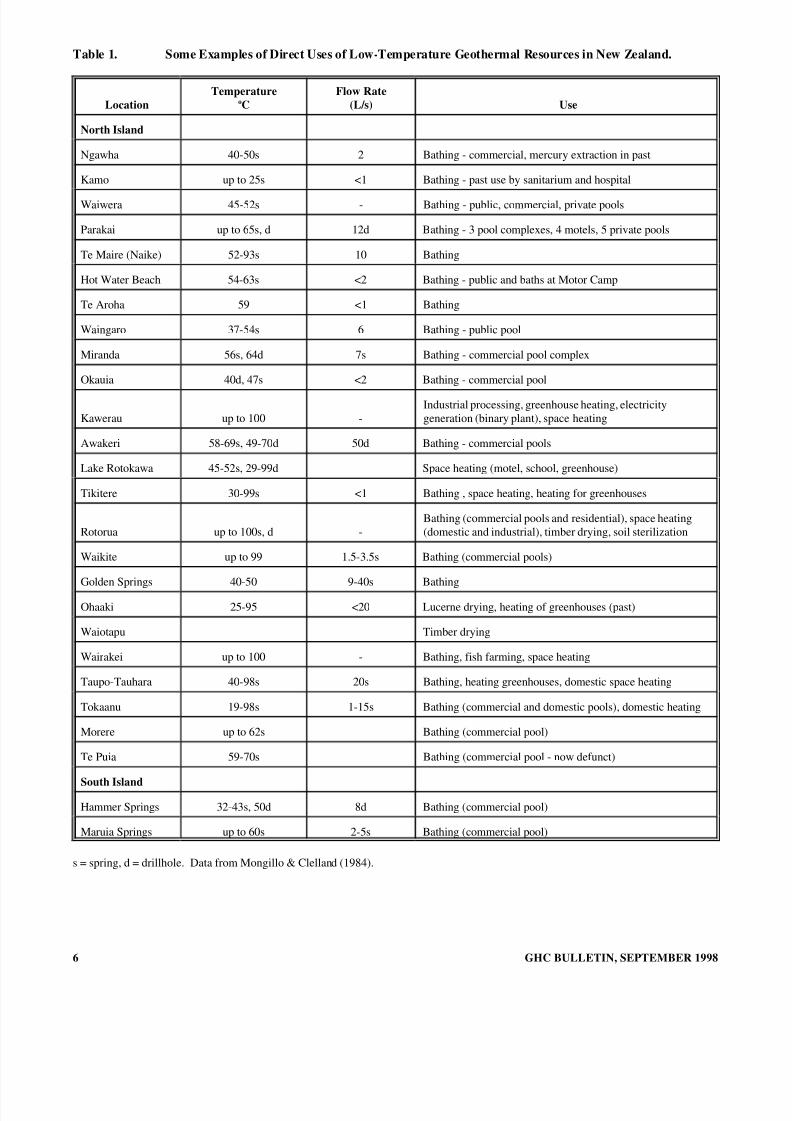
Table 1. Some Examples of Direct Uses of Low-Temperature Geothermal Resources in New Zealand.
LocationTemperature
oCFlow Rate
(L/s) Use
North Island
Ngawha 40-50s 2 Bathing - commercial, mercury extraction in past
Kamo up to 25s <1 Bathing - past use by sanitarium and hospital
Waiwera 45-52s - Bathing - public, commercial, private pools
Parakai up to 65s, d 12d Bathing - 3 pool complexes, 4 motels, 5 private pools
Te Maire (Naike) 52-93s 10 Bathing
Hot Water Beach 54-63s <2 Bathing - public and baths at Motor Camp
Te Aroha 59 <1 Bathing
Waingaro 37-54s 6 Bathing - public pool
Miranda 56s, 64d 7s Bathing - commercial pool complex
Okauia 40d, 47s <2 Bathing - commercial pool
Kawerau up to 100 -Industrial processing, greenhouse heating, electricitygeneration (binary plant), space heating
Awakeri 58-69s, 49-70d 50d Bathing - commercial pools
Lake Rotokawa 45-52s, 29-99d Space heating (motel, school, greenhouse)
Tikitere 30-99s <1 Bathing , space heating, heating for greenhouses
Rotorua up to 100s, d -Bathing (commercial pools and residential), space heating(domestic and industrial), timber drying, soil sterilization
Waikite up to 99 1.5-3.5s Bathing (commercial pools)
Golden Springs 40-50 9-40s Bathing
Ohaaki 25-95 <20 Lucerne drying, heating of greenhouses (past)
Waiotapu Timber drying
Wairakei up to 100 - Bathing, fish farming, space heating
Taupo-Tauhara 40-98s 20s Bathing, heating greenhouses, domestic space heating
Tokaanu 19-98s 1-15s Bathing (commercial and domestic pools), domestic heating
Morere up to 62s Bathing (commercial pool)
Te Puia 59-70s Bathing (commercial pool - now defunct)
South Island
Hammer Springs 32-43s, 50d 8d Bathing (commercial pool)
Maruia Springs up to 60s 2-5s Bathing (commercial pool)
s = spring, d = drillhole. Data from Mongillo & Clelland (1984).
6 GHC BULLETIN, SEPTEMBER 1998
8/8/2019 September 1998 Geo-Heat Center Quarterly Bulletin
http://slidepdf.com/reader/full/september-1998-geo-heat-center-quarterly-bulletin 9/40
generally been found accidently by explorers, mineralprospectors, farmers, and trampers. It is unlikely that any newlow-temperature geothermal springs of significant size or flowrate will be discovered; but, it is probable that additionallocalized areas of warm groundwater will be found.
At present, the main use of low-temperature watersin New Zealand is for bathing (Table 1). Public baths operateat Kamo, Waiwera, Parakai, Miranda, Te Maire, Waingaro,Hot Water Beach, Okauia (Matamata), Te Aroha, Tauranga,Awakeri, Te Puia, Morere, Hammer, and Maruia. A historyof the use of some of these springs is given in the book Taking the Waters - Early Spas in New Zealand by IanRockel (1986).
HIGH-TEMPERATURE VOLCANIC GEOTHERMALSYSTEMS
Only the upper parts of volcanic geothermal systemshave been investigated by drilling. The deeper parts havebeen probed by geophysical techniques and their behavior isdeduced theoretically from mathematical models or from scalemodels in the laboratory. A conceptual model of a volcanicgeothermal system is that meteoric waters percolate downfrom the surface to depths of 5 - 10 km where they becomeheated by hot (up to 800 oC) volcanic rock, such as a magmabody. Although such shallow bodies are believed to be theprime source of heat for high-temperature geothermal waters,no such body has yet been positively identified beneath any of the known volcanic geothermal systems in New Zealand, andtheir shape, size, depth and chemistry remain largelyspeculative. The waters become heated and interactchemically with the volcanic rock; then, being of lowerdensity than the surrounding water, they rise in a plume,towards the surface through pores and fractures in theoverlying rocks.
Once established, this plume is remarkably stable andthe water rises vertically, seeking permeable paths to thesurface. Although the temperatures may be several hundreddegrees, the pressures at depth are such that the water does notboil. As the water rises, cooler water from the adjacent rocksmay be entrained in the plume, reducing the temperature anddiluting the concentrations of dissolved salts. Near thesurface, a number of factors can complicate the flow: reducedpressures can cause local boiling, the geological structures inthe rocks can channel flow, and surface waters can infiltratethe system.
Maori tradition has a different origin for the volcanicgeothermal systems. Their legend is that when Ngatoroirangi(chief of the Te Arawa tribe) and Ngauruhoe (his slave), wereexploring the Taupo Volcanic Zone they climbed the slopes of Mount Tongariro and were close to dying from the cold.Ngatoroirangi called to his sisters, Kuiwai and Haungaroa, inHawaiki across the Pacific Ocean, to send heat to resuscitatethem. The sisters heard his cry for help, and with the fire godsPupu and Te Hoata, set out underground to bring heat. In thesearch for their brother, they stopped and came to the surfaceto look for him at places on the way. Their route led from
GHC BULLETIN, SEPTEMBER 1998
Whakaari (White Island), puia Moutohora (Whale Island),Okakaru, Rotoehu, Rotoiti, Tarawera, Paeroa (Waikite),Orakeikorako, Taupo, and Tokaanu, to Tongariro. Wherethey stopped, the heat burst out as thermal activity, andremains as ngawha (overflowing pools), puia (volcanoes, hotsprings), and wairiki (hot springs).
At the surface, the volcanic geothermal systems arecharacterized by groups of thermal features within an area of 5 to 15 km 2. The natural discharge of energy from thesefeatures can be considerable. Before exploitation, WairakeiGeothermal Area discharged more than 600 megawatts (MW)of heat, with one feature alone (Karapiti Blowhole)discharging 12 MW.
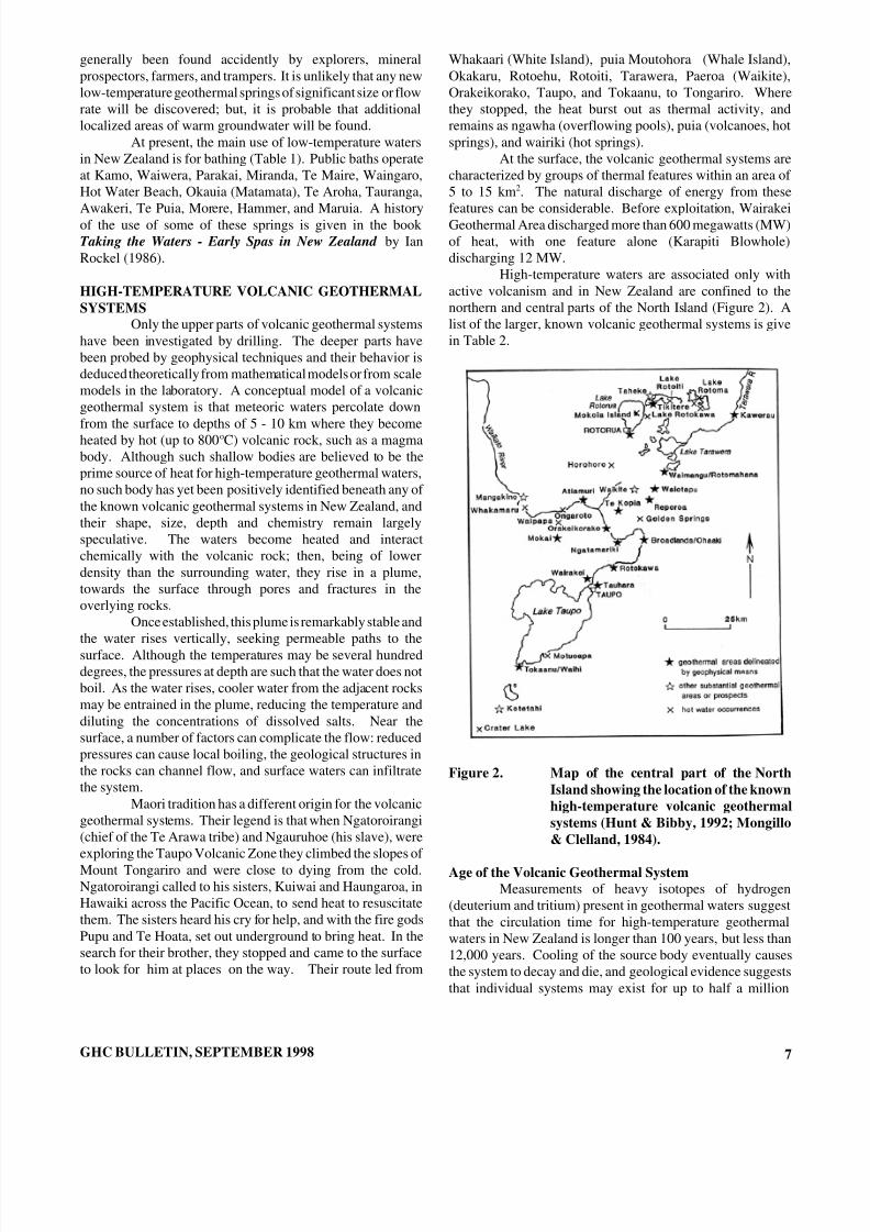
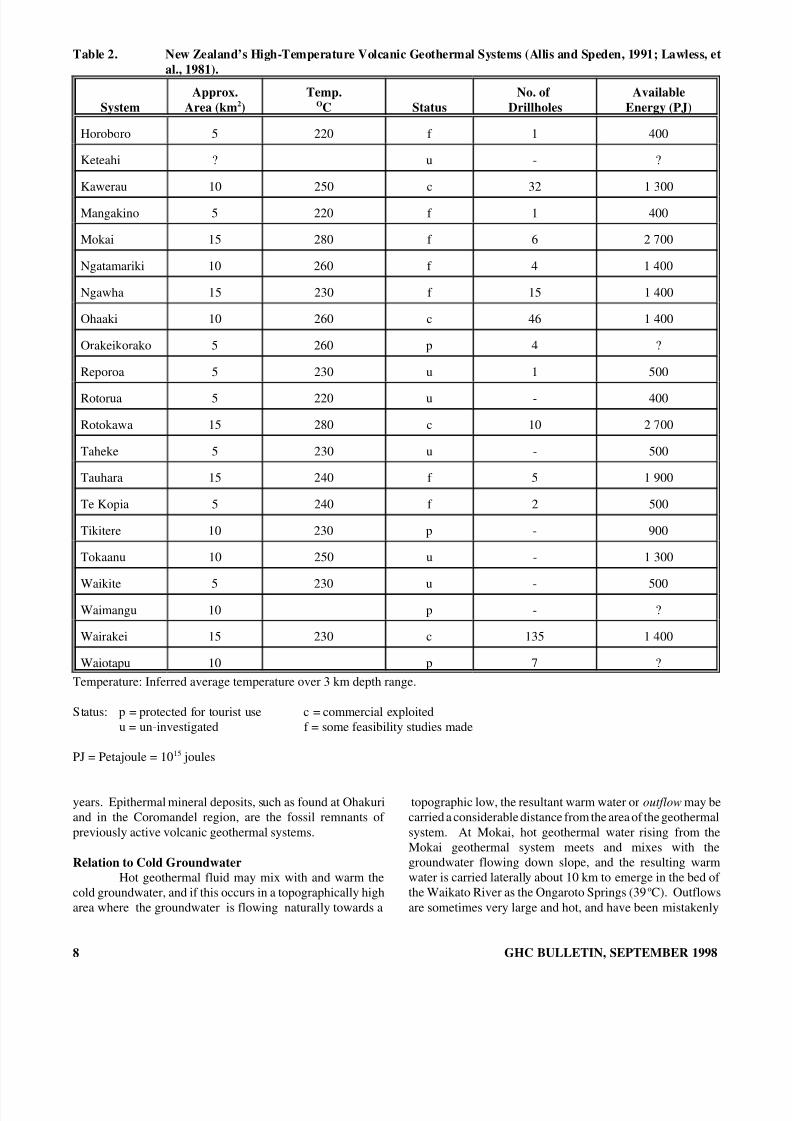
High-temperature waters are associated only withactive volcanism and in New Zealand are confined to thenorthern and central parts of the North Island (Figure 2). Alist of the larger, known volcanic geothermal systems is givein Table 2.
Figure 2. Map of the central part of the NorthIsland showing the location of the knownhigh-temperature volcanic geothermalsystems (Hunt & Bibby, 1992; Mongillo& Clelland, 1984).
Age of the Volcanic Geothermal SystemMeasurements of heavy isotopes of hydrogen
(deuterium and tritium) present in geothermal waters suggestthat the circulation time for high-temperature geothermalwaters in New Zealand is longer than 100 years, but less than12,000 years. Cooling of the source body eventually causesthe system to decay and die, and geological evidence suggeststhat individual systems may exist for up to half a million
7
8/8/2019 September 1998 Geo-Heat Center Quarterly Bulletin
http://slidepdf.com/reader/full/september-1998-geo-heat-center-quarterly-bulletin 10/40

8/8/2019 September 1998 Geo-Heat Center Quarterly Bulletin
http://slidepdf.com/reader/full/september-1998-geo-heat-center-quarterly-bulletin 11/40
though to indicate the presence of a geothermal systems belowthe place where they emerge, until drilling or geophysicalmeasurements show that only a thin layer of hot water isflowing near the top of a zone of cold groundwater.
USE OF GEOTHERMAL RESOURCESThere are several ways in which geothermal energy
is used in New Zealand:
1. Direct use - the heat is used directly (e.g., spaceheating, heating of swimming pools, drying andprocessing agricultural products.
2. Conversion to another form of energy (e.g.,production of electricity).
3. Recovery of minerals (e.g., recovery of silica,lithium, boron, etc., from the waters).
The greatest use of geothermal water in New Zealandis for generating electricity. When a deep geothermal well isdischarged, the emerging fluid is a mixture of liquid water(about 80% by mass) and steam. The steam is separated andpiped to the power station. The water, together withcondensed steam from the power station, is disposed of eitherby putting it into a nearby river or by pumping it back into theground.
Figure 3. Geyser, Whakarewarewa, Rotorua.
GHC BULLETIN, SEPTEMBER 1998
Figure 4. Lake Rotomahana ( from Post OfficePhilatelic Bureau Stamp).
REFERENCES
Allis & Speden, 1991.
Hunt, T. M. and H. M. Bibby, 1992. Geothermal Hydrologyin Waters of New Zealand . New Zealand Hydro-logical Society.
Lawless, et al., 1981.
Mongillo, M. and L. Clelland, 1984. Concise Listing of Information on the Thermal Areas and ThermalSprings of New Zealand , DSIR Geothermal Report 9,DSIR, Wellington, New Zealand, 228 p.
Rockel, I., 1985. Taking the Waters - Early Spas in New Zealand, Government Printing Office, Wellington,New Zealand, 195 p.
9

8/8/2019 September 1998 Geo-Heat Center Quarterly Bulletin
http://slidepdf.com/reader/full/september-1998-geo-heat-center-quarterly-bulletin 12/40
DOMESTIC AND COMMERCIAL HEATING & BATHINGROTORUA AREA
Ross AndersonDesignated Project Manager
Kingston Morrison Ltd.
INTRODUCTIONGeothermal resources in the Rotorua area have been
put to a number of practical uses, many of which are describedin this article.
The use of the geothermal resource in this region hasa long history, well and truly pre-dating European settlement.The earliest uses were for bathing, washing and cooking, thesebeing made possible by the existence of suitable naturalfeatures.
Today, geothermal is applied to a variety of domesticand commercial heating and other purposes. It is used forboth the heat it can provide and the “mineral” water content of the fluid; however, geothermal is not available over the wholecity.
Increasing usage during the post-war decades waslinked to the apparent decline natural activity atWhakarewarewa. In the 1980s, the government implementeda control program that, amid other things, resulted in theclosure of wells within 1.5 km of Pohutu geyser.
CURRENT USES OF THE GEOTHERMAL RESOURCE
ParklaneThis is a housing development with a geothermal
group heating scheme. There are 13 units on this site, whichshare a well with six other dwellings on adjoining properties.
Sixteen of the total are supplied with a circulating supply of hot water from a single heat exchanger. The other threereceive geothermal fluid and have their own, smaller heatexchanger arrangements. This is a relatively early example of a scheme that distributes secondary water rather thanrecirculating geothermal fluid. The heat is used for spaceheating, domestic hot water heating, and, in some cases,heating small pools.
This system is quite successful and relatively neat,with much of its distribution piping underground. However,there are a number of design weaknesses which havecontributed to piping corrosion, internal and external, anddifficulty in getting adequate circulation to some users.
Queen Elizabeth HospitalQueen Elizabeth Hospital is an example of
institutional use of geothermal. Geothermal fluid is used notonly for space heating and domestic hot water heating; but, thewater phase is taken for therapeutic purposes.
10
Millennium HotelCommercial use of geothermal occurs in a number of
hotels and motels, and other facilities. The Millennium Hotelis a case in point. Here geothermal is used for space heating,domestic hot water heating, pool heating (in this case, amedium-sized swimming pool and a number of spa pools, allusing fresh water). High-temperature hot water is also gen-erated for cooling purposes and, perhaps the most interestingof all, there is an absorption chiller for the air-conditioning.
Aquatic CentreThe Rotorua District Council’s Aquatic Centre is
another good example of the use of geothermal on a relativelylarge scale. This complex has two indoor pools and a largeroutdoor pool. All three are heated. In addition, geothermalenergy is used for space heating and for domestic hot waterheating.
All of the geothermal fluid is passed through a singleplate-type heat exchanger, which heats the secondary water,which is a circulating system of town water. This, in turn,supplies all the various heating services.
In this case, because of the high capacity of thegeothermal heating system, the domestic hot water (DHW)supply (used for showers and hand basins) is heated on an as-required basis, avoiding the cost of installing a large storagecalorifier. The cold mains water feed is passed through a
small heat exchanger fitted with an automatic temperaturecontrol. There is a small buffer tank in the circuit, sized toabsorb the swings in temperature in the hot water that occurwhen there is a big change in the demand.
Figure 1. Aquatic Center indoor pool.
GHC BULLETIN, SEPTEMBER 1998
8/8/2019 September 1998 Geo-Heat Center Quarterly Bulletin
http://slidepdf.com/reader/full/september-1998-geo-heat-center-quarterly-bulletin 13/40
The ventilation system for the pool building has beendesigned to minimize chlorine odor and keep the internalatmosphere as pleasant as possible. To achieve this, arelatively high air flow rate, once-through system has beenprovided. No air is recirculated. The incoming air is heatedto maintain the building’s internal temperature. A heat pipe,heat recovery unit has been incorporated to significantlyreduce the high heat losses that would otherwise occur. Thehot, moist, chlorine-laden air being extracted gives up most of
its heat as it passes through the heat recovery unit, which usesit to preheat the incoming air. This unit recovers about 75%of the heat in the exhaust air. The heating of the fresh air iscompleted by a heating coil through which low-temperaturehot water (LTHW) is circulated.
OTHER EXISTING USES
Space heating generally refers to the provision of comfort heating in an occupied building. Another variant isin-building heating for commercial purposes such asglasshouse operations. The Rotorua District Council nurseryin the Government Gardens is a case in point.
Space heating is virtually always accomplished bythe use of a LTHW system. This is a system in which a heatsource–in this case hot geothermal fluid–is used to heat“clean” secondary water. “Low” temperature in this contextdoes not mean cold. It refers to a heating system operating ata relatively low temperature, typically less than 100 oC. Thesecondary water is circulated through a heat dissipatingdevice, usually flat panel-type radiators, but sometimes fancoil units, unit heaters or bare pipes.
Domestic hot water (DHW) means hot tap water,used for normal washing and sanitary purposes, in dwellingsand other premises. DHW heating is a natural adjunct tospace heating where geothermal is employed as heat isnormally available throughout the year. This is not always thecase with LTHW heating systems which are fueled by gas orcoal since they are often only put into service during theheating season and the DHW is heated by electricity to assurea year-round supply.
Pool heating is one of the major uses of geothermal.Pools either contain town water which is heated bygeothermal, as at the Aquatic Centre, or geothermal water(“mineral” pools).
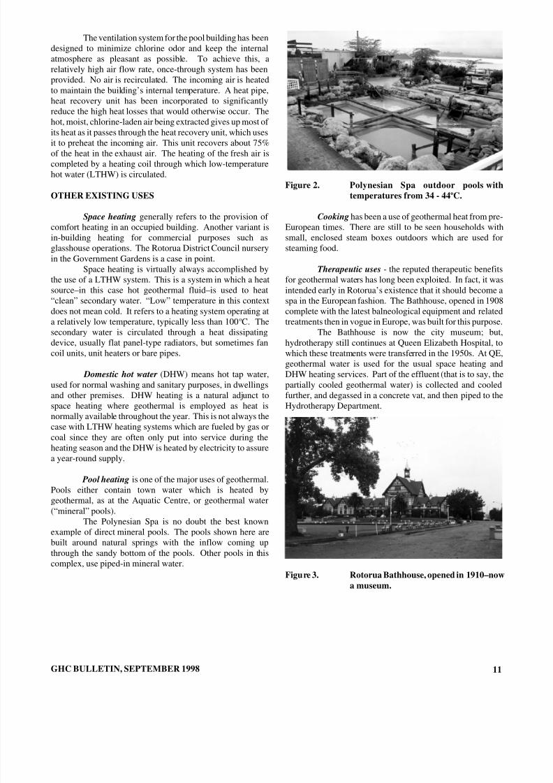
The Polynesian Spa is no doubt the best knownexample of direct mineral pools. The pools shown here arebuilt around natural springs with the inflow coming upthrough the sandy bottom of the pools. Other pools in thiscomplex, use piped-in mineral water.
GHC BULLETIN, SEPTEMBER 1998
Figure 2. Polynesian Spa outdoor pools withtemperatures from 34 - 44 oC.
Cooking has been a use of geothermal heat from pre-European times. There are still to be seen households withsmall, enclosed steam boxes outdoors which are used forsteaming food.
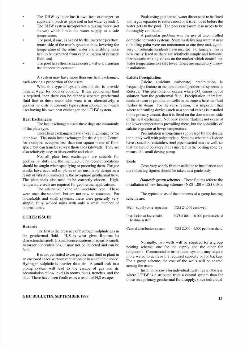
Therapeutic uses - the reputed therapeutic benefitsfor geothermal waters has long been exploited. In fact, it wasintended early in Rotorua’s existence that it should become aspa in the European fashion. The Bathhouse, opened in 1908complete with the latest balneological equipment and relatedtreatments then in vogue in Europe, was built for this purpose.
The Bathhouse is now the city museum; but,hydrotherapy still continues at Queen Elizabeth Hospital, towhich these treatments were transferred in the 1950s. At QE,geothermal water is used for the usual space heating andDHW heating services. Part of the effluent (that is to say, thepartially cooled geothermal water) is collected and cooledfurther, and degassed in a concrete vat, and then piped to theHydrotherapy Department.
Figure 3. Rotorua Bathhouse, opened in 1910–nowa museum.
11

8/8/2019 September 1998 Geo-Heat Center Quarterly Bulletin
http://slidepdf.com/reader/full/september-1998-geo-heat-center-quarterly-bulletin 14/40
SYSTEMS, PROCESSES AND EQUIPMENT
WellsTwo systems of heat extraction are used:
• fluid removal and re-injection• downhole heat exchangers.
The former are by far the more common, there being
about 240 operative in this area, of which about 100 are fordomestic systems. Wells of this type typically can havemaximum outputs of the order of 1 to 3 MW (thermal).
Referring to the extraction and re-injection system,supply wells in Rotorua can be classified as self-starting, self-sustaining, and pumped.
Self-starting wells will, when shutdown, maintain apressure against the stop valve and will flow again when thevalve is opened.
Self-sustaining wells do not maintain a positive well-side pressure when shut down and do not flow of their ownaccord when the shutoff valve is opened. Flow is induced byintroducing compressed air into the well. Once a flow hasbeen established, it will then continue without furtherassistance. The majority in Rotorua are of this type.
Pumped wells cannot be induced to flow withoutassistance and have to be continuously pumped or air assisted.The ususal process is to air lift the fluid. This is sensible inthat the operating conditions of temperature and fluid con-tamination are very severe for mechanical pumps. However,the continuous introduction of air into a well has long-termcorrosion implications.
The vast majority of wells in Rotorua have 100-mmdiameter production casings; although, sizes from 65 to 125mm do exist. The smaller sizes are often larger wells whichhave been repaired by fitting a sleeve inside the casing. Wellsin Rotorua are typically about 100 m deep, ranging from about45 to 190 m. Aquifer temperatures vary from about 125 to175oC.
Distribution Systems
Distribution of the geothermal energy can be eitherby piping the geothermal fluid to each user or by employinga central heat exchanger and piping a circulating supply of low-temperature hot water (LTHW). Both types of systemsare used. Systems can be a hybrid of the two.
Figure 4 is a schematic diagram of a well conceivedsystem of the second type (LTHW distribution), which is quiteclose to the Parklane system referred to earlier.
The principal features are:
• A single heat exchanger supplies LTHW to a numberof users,
• The geothermal effluent goes to a deep injectionwell,
• The flow of geothermal is controlled to maintain thesecondary water supply temperature constant,
• The temperature control valve is on the outgoing sideof the heat exchanger,
• The isolation valves are fitted, to enable the user’ssystem to be shutoff from the main system,
• Space heating is by radiators fitted with thermostaticvalves,
Figure 4. Group heating scheme - based on the reticulation of low-temperature hot water.
12 GHC BULLETIN, SEPTEMBER 1998
8/8/2019 September 1998 Geo-Heat Center Quarterly Bulletin
http://slidepdf.com/reader/full/september-1998-geo-heat-center-quarterly-bulletin 15/40
• The DHW cylinder has it own heat exchanger, orequivalent (such as pipe coil in hot water cylinder),
• The DHW system incorporates a mixing valve (notshown) which limits the water supply to a safetemperature,
• The pool, if any, is heated by the lower temperature,return side of the user’s systems; thus, lowering thetemperature of the return water and enabling moreheat to be extracted from each kilogram of primary
fluid, and• The pool has a thermostatic control valve to maintainits temperature constant.
A system may have more than one heat exchanger,each serving a proportion of the users.
What this type of system des not do, is providemineral water for pools or cooking. If raw geothermal fluidis required, then there can be either a separate geothermalfluid line to those users who want it or, alternatively, ageothermal distribution-only type system adopted, with eachuser having his own heat exchanger and LTHW system.
Heat ExchangersThe heat exchangers used these days are commonly
of the plate type.These heat exchangers have a very high capacity for
their size. The main heat exchanger for the Aquatic Centre,for example, occupies less than one square meter of floorspace, but can transfer several thousands kilowatts. They arealso relatively easy to disassemble and clean.
Not all plate heat exchangers are suitable forgeothermal duty and the manufacturer’s recommendationsshould be sought when specifying or procuring them. Fatiguecracks have occurred in plates of an unsuitable design as aresult of vibration induced by the two-phase geothermal flow.The plate seals also need to be correctly chosen. High-temperature seals are required for geothermal applications.
The alternative is the shell-and-tube type. Thesewere once the standard, but are not now so common. Forhouseholds and small systems, these were generally verysimple, fully welded units with only a small number of internal tubes.
OTHER ISSUES
HazardsThe first is the presence of hydrogen sulphide gas in
the geothermal fluid. H 2S is what gives Rotorua itscharacteristic smell. In small concentrations, it is easily smelt.In larger concentrations, it may not be detected and can befatal.
It is not permitted to use geothermal fluid in plant inan enclosed space without ventilation or in a habitable space.Hydrogen sulphide is heavier than air. A small leak in apiping system will lead to the escape of gas and itsaccumulation at low levels in rooms, ducts, trenches, and thelike. There have been fatalities as a result of H 2S escape.
GHC BULLETIN, SEPTEMBER 1998
Pools using geothermal water direct need to be fittedwith a gas separator to ensure most of it is removed before thewater gets to the pool. The pools enclosure also needs to bethoroughly ventilated.
A particular problem was the use of uncontrolleddomestic hot water systems. Systems delivering water at nearto boiling point were not uncommon at one time and, again,very unfortunate accidents have resulted. Fortunately, this isnow easily fixed as there are relatively simple and low-cost
thermostatic mixing valves on the market which control thewater temperature to a safe level. These are mandatory in newinstallations.
Calcite PrecipitationCalcite (calcium carbonate) precipitation is
frequently a feature in the operation of geothermal systems inRotorua. This phenomenon occurs where CO 2 comes out of solution from the geothermal fluid. Precipitation, therefore,tends to occur in production wells in the zone where the fluidflashes to steam. For the same reason, it is important thatwhere a throttling device (such as a control valve) is installedin the primary circuit, that it is fitted on the downstream sideof the heat exchanger. Not only should flashing not occur atthe lower temperatures prevailing there, but the solubility of calcite is greater at lower temperature.
Precipitation is sometimes suppressed by the dosingthe supply well with polyacrylate. Systems where this is donehave a small bore stainless steel pipe inserted into the well, sothat the liquid polyacrylate is injected in the boiling zone bymeans of a small dosing pump.
CostsCosts vary widely from installation to installation and
the following figures should be taken as a guide only
Domestic group schemes - These figures refer to theinstallation of new heating schemes (NZ$ 1.00 = US$ 0.50).
The typical costs of the elements of a group heatingscheme are:
Well - supply or re-injection NZ$ 24,000 each well
Installation of household NZ$ 8,000 - 16,000 per householdheating system
Central distribution system NZ$ 2,000 - 4,000 per household
Normally, two wells will be required for a groupheating scheme: one for the supply and the other forreinjection. Commercial or institutional systems may requiremore wells, to achieve the required capacity or for backup.For a group scheme, the cost of the wells will be sharedamong the users.
Installation costs for individual dwellings will be lesswhere LTHW is distributed from a central system than forthose on a primary geothermal fluid supply, since individual
13
8/8/2019 September 1998 Geo-Heat Center Quarterly Bulletin
http://slidepdf.com/reader/full/september-1998-geo-heat-center-quarterly-bulletin 16/40
heat exchangers and some control elements are not required.However, a connection charge, to the central system will begreater because of the greater complexity and cost of thatsystem.
For each user on a new scheme, the minimum costwill be about NZ$ 12,000, covering a share of two wells, ashare of the distribution network, central heat exchanger andrelated equipment, and the user’s own in-house equipmentcosts. The cost could well be considerably greater.
Running costs are likely to be of the order of NZ$ 20- 40 per month, say $300 per year.The monthly operating charge can vary significantly,
depending on how the operating syndicate structures itscharges and what items it covers. Charges need to recoverwell clean outs (about NZ$ 1,000 a time) which may berequired very few months or at intervals of several years,general maintenance, well inspection costs and, if applicable,doing chemical costs. In addition, charges may be levied forlong-term equipment replacement or for capital recovery.
Comparison with electric heating - A comparisonwith electricity, normally regarded as a high-running costoption, is instructive. An all-electric home, operated modestlyand economically, is likely to spend NZ$ 1,200 per year onpower, of which about $700 will be for water heating andspace heating. On the (unlikely) basis that a geothermally-heated home used the same amount of energy, then:
Cost of geothermal system NZ$ 12,000Annual running cost NZ$ 300Electricity cost NZ$ 700Annual savings in operating cost NZ$ 400Rate of return 3.3%
Clearly, a geothermal user, not having to pay a unitcharge for geothermal heat, will consume more energy.However, even if the consumption was four times that of theordinary electricity user, the return on capital is still onlyabout 13%.
A geothermal system for domestic heating is not,generally, a sound investment when the full cost of installinga new complete heating scheme has to be paid; although, itshould be noted that each situation needs to be judged on itsown merits. If pool heating is required, for example, theeconomics changes significantly.
The situation becomes less clear when considering aproperty in which geothermal is already installed. In this case,the premium, if any, that one pays for such a property,becomes the capital cost element. Valuers will add about NZ$2,500 to 3,000 to the value of a typical property, and up to$5,000 for a very large dwelling if geothermal heating isinstalled.
Large-scale users - The economics can be verydifferent for large-scale users. In many cases, particularlywith institutional users, fossil fueled heating systems will be
14
of the low- or medium-temperature hot water type, similar toa geothermal system. In the one case, the secondary systemwill be heated by a boiler and the other with a heat exchanger;but, the secondary circuit system will be the same.
The equipment costs will be of a similar order of cost, unless of course, boiler plant is also installed to providebackup capacity.
Apart from the plant maintenance costs and minoritems such as bore inspections, the energy costs are zero.
Of the large users in Rotorua, the Aquatic Centre hasannual maintenance costs for its geothermal system of NZ$20,000. If natural gas were used to provide the energy, theestimated gas cost would be around $150,000. Another majoruser has heating plant maintenance costs of around $5,000 peryear and achieves a similar energy cost savings,conservatively estimated at NZ$ 140,000 per annum.
SUMMARY
• Geothermal has been successfully used in Rotoruafor many years,
• Geothermal energy is principally used for heating:space heating, domestic hot water and fresh waterpool heating.
• Mineral pools, using geothermal water direct, arealso a significant use,
• Most systems obtain the energy by using a well toextract geothermal fluid (water, steam and non-condensable gases), which is passed through a heatexchanger to heat fresh water and is then reinjected,preferably to the geothermal aquifer.
• Historically, geothermal heating systems, small-scalesystems in particular, were simple and relativelyprimitive and had low-energy efficiency,
• The use of geothermal is being greatly improved bythe use of appropriate designs and automaticcontrols, both in terms of energy use efficiency andthe effectiveness, benefit and safety of the results,
• For households and small installations, geothermalheating has a high capital cost and the economics arepoor, and
• For large installations, the capital costs are more akinto fueled heating systems. The unit incremental costof the heat obtained (over and above the fixed costs)is very small. There is, therefore, little capital costpenalty for using geothermal, but potentially majorsavings in running costs. The economics of largesystems can be excellent.
GHC BULLETIN, SEPTEMBER 1998

8/8/2019 September 1998 Geo-Heat Center Quarterly Bulletin
http://slidepdf.com/reader/full/september-1998-geo-heat-center-quarterly-bulletin 17/40
KAWERAU GEOTHERMAL DEVELOPMENT:A CASE STUDY
Andy BloomerDowner Energy Services, Ltd. Wairakei, New Zealand
DEVELOPMENT HISTORYThe Kawerau geothermal field covers an area of 19
to 35 km 2. Fluid temperatures exceed 310 oC. Drilling beganat the end of 1952, using experience gained at the Wairakeigeothermal field. A significant area of the field to the southand east lying within the resistivity boundary is virtuallyunexplored. Production is currently limited to an area of about a square km located just north of the mill (Figure 1).
The steamfield is owned by the New ZealandGovernment (who under New Zealand law, owns allgeothermal resources). The steamfield is managed by theengineering firm Connell Wagner, with day-to-day operationsand maintenance being contracted to Downer Energy.
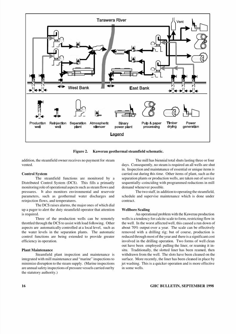
Figure 1. Kawerau geothermal steamfield.
MillThe Tasman Pulp and Paper Company Ltd. mill is
sited at Kawerau, partly because of the presence of thegeothermal steamfield. The steamfield has been supplying
geothermal steam since 1957.Geothermal provides 30% of the mill’s process steam
and 5% of electrical energy. Steam flow is up to 320 t/h witha total annual supply of about 2.3 million tonnes; that is amean flow of around 265 tonnes/hour. The peak flow isequivalent to 40 to 45 MW(e).
Geothermal steam is the cheapest external energysource at Kawerau. (The cheapest fuel is “black liquor” andtimber waste). The geothermal steam price is determined
GHC BULLETIN, SEPTEMBER 1998
on the basis of the next cheapest energy option, with benefitsbeing shared between supplier and user.
Geothermal steam is used both directly in the millprocesses, and in heat exchangers. Electricity is generated inan 8-MW turbo alternator (T/A), with the exhaust steam beingfurther used to heat process water. The T/A is used to balanceprocess steam flows, so does not have a high-load factor.
An interesting by-product of the geothermal processis the condensed steam. All the condensate from within themill is collected, after having the non-condensable gasesstripped out it, is used to provide high-quality boiler feedwater. The ammonia naturally present in the steam providesa built-in corrosion inhibitor, so that dosing with amines is nolonger required (Carter and Hotson, 1992).
Other UsesHigh-pressure steam is also supplied to the Fletcher
Challenge Forests sawmill for drying timber in kilns. In linewith increasing demand for kiln dried lumber, FletcherChallenge Forests propose installing a further five geothermal-heated kilns and converting the non-geothermal kilns togeothermal (Figure 2).
Some of the separated geothermal water is used togenerate electricity in two “binary cycle” electricity generatingplants with a total capacity of about 6 MW(e). Smallquantities of steam are also used for greenhouse heating.
OPERATIONAL ASPECTS
CharacteristicsProduction of steam from the steamfield is a
continuous operation: 24 hours per day, 360 plus days peryear. Currently, five wells are producing and two are used forreinjection. Other wells are used for monitoring on acontinuous or periodic basis.
Steam is supplied for process heat and to power aturbo alternator. Unlike a power plant providing base load,the mill operation fluctuates, so the steamfield has beendesigned for load following. Changes in demand can be verysudden with changes in the pulp and paper process–although,the demand is smoothed to some extent by the turbo alternator,which usually runs off maximum load.
Pressure is controlled by venting steam when demanddecreases, as it is not possible to throttle the wells in the shorttime required. Well are, however, throttled if demand is to bereduced for some period, to reduce the amount of steam lostthrough the steam vents. Resource consents are required fordischarge to atmosphere–a condition of the consents is tominimize venting. This arises from the requirement tomaximize efficient use of the geothermal resource. In
15
8/8/2019 September 1998 Geo-Heat Center Quarterly Bulletin
http://slidepdf.com/reader/full/september-1998-geo-heat-center-quarterly-bulletin 18/40
Figure 2. Kawerau geothermal steamfield schematic.
addition, the steamfield owner receives no payment for steamvented.
Control SystemThe steamfield functions are monitored by aDistributed Control System (DCS). This fills a primarilymonitoring role of operational aspects such as steam flows andpressures. It also monitors environmental and reservoirparameters, such as geothermal water discharges andreinjection flows, and temperatures.
The DCS raises alarms, the major ones of which dialup a pager to alert the duty steamfield operator that attentionis required.
Three of the production wells can be remotelythrottled through the DCS to assist with load following. Otheraspects are automatically controlled at a local level, such asthe water levels in the separation plants. The automaticcontrol functions are being extended to provide greaterefficiency in operation.
Plant MaintenanceSteamfield plant inspection and maintenance is
integrated with mill maintenance and “marine” inspections tominimize disruption to the steam supply. (Marine inspectionsare annual safety inspections of pressure vessels carried out bythe statutory authority.)
16
The mill has biennial total shuts lasting three or fourdays. Consequently, no steam is required an all wells are shutin. Inspection and maintenance of essential or unique items is
carried out during this time. Other items of plant, such as theseparation plants or production wells, are taken out of servicesequentially–coinciding with programmed reductions in milldemand whenever possible.
The two staff, in addition to operating the steamfield,schedule and supervise maintenance which is done undercontract.
Wellbore ScalingAn operational problem with the Kawerau production
wells is a tendency for calcite scale to form, restricting flow inthe well. In the worst affected well, this caused a run down of about 70% output over a year. The scale can be effectivelyremoved with a drilling rig; but of course, production isreduced through most of the year and there is a significant costinvolved in the drilling operation. Two forms of well cleanout have been employed: pulling the liner, or reaming it in-situ. Traditionally, the slotted liner has been reamed, thenwithdrawn from the well. The slots have been cleaned on thesurface. More recently, the liner has been cleaned in place by
jet washing. This is a quicker operation and is more effectivein some wells.
GHC BULLETIN, SEPTEMBER 1998

8/8/2019 September 1998 Geo-Heat Center Quarterly Bulletin
http://slidepdf.com/reader/full/september-1998-geo-heat-center-quarterly-bulletin 19/40
MonitoringExtensive monitoring is carried out. This includes
monitoring of environmental impacts such as heat and chemi-cals discharged to the Tarawera River and subsidence. It alsoincludes extensive reservoir monitoring. Information fromthis is used to prepare and update a model of the geothermalreservoir. This in turn is used to predict future changes inthe reservoir from different resource management strategies–such as increased production or reinjection into different
locations (White, et al., 1997).HOW THE STEAMFIELD HAS REACTED TODEVELOPMENTWells
The years of production have had little effect on thereservoir itself, pressure decline in the deep reservoir is lessthan measurement error; though, there has been some declinein temperature (Allis, 1997).
Not every management strategy is successful; but, theless successful are useful for learning more about the resourceand development techniques. (Kawerau was using geothermalsteam a couple of years before Wairakei, and these fields werethe first wet geothermal fields to be developed in the world.)Cold groundwater inflows caused the demise of some of theearliest wells with their relatively shallow casings. Wells arenow drilled and cased through the volcanic strata overlyingthe basement to prevent the intrusion of cooler water. Wellsdrilled in this manner have been very successful. KA19 isnow into its 27 th year of production, still producing over 70 t/hof steam.
KA21 has been producing for over 20 years and putsout well in excess of 100 t/h of steam-equivalent to 18MWelectrical. KA27 has produced for 17 years, KA35 for 10years and KA36 for 5 years. However, well KA28 which waslinked into the system in 1986, was retired two years laterowing to a long-term cyclic reductions in output.
ReinjectionUnlike all current or future geothermal field
developments in New Zealand, where reinjection will beincorporated into the process from the start, waste water atKawerau has been traditionally discharged to the TaraweraRiver. Reinjection has been under investigation for about 12years, including reservoir studies and field trials.
Reinjection, commenced in 1991, has increased up topeak flow rates in excess of 300 t/h. However, the annualaverage is about 250 t/h or about a quarter of the separatedwater. Separated water from the separation plants is pipedunder pressure to the reinjection wells. Currently, there aretwo separate systems, with a reinjection well on each bank of the Tarawera River, receiving water from an individualseparation plant.
The east bank reinjection flow is passed throughbinary generating plant “TG1 prior to reinjection; this removesheat from the water. Injection temperature being around 110to 130 oC. The flow to the west bank reinjection well is notused in binary plant; so, the reinjection temperature is
GHC BULLETIN, SEPTEMBER 1998
higher–about 180 oC. However, part of the flow from theseparation plants on the bank is used in binary generatingplant “TG2.”
The injectivity of the first well, KAM1, has declinedover time. The well now swallows about 60 t/h compared toabout 130 t/h when first commissioned. It is believed that thisdecline is caused by deposition of super-saturated silica withinthe formation. On the other hand, reinjection well KA38increased in swallowing capacity over the first threeyears–increasing from about 100 t/h to over 200 t/h. Itsinjectivity has since remained over 200 t/h.
Although reinjection has the potential to providerecharge to a system where mass extraction has resulted inpressure drawdown. At Kawerau, pressure drawdown overthe period of field development is negligible. The task is tominimize the effect of the cold front spreading from thereinjection wells and affecting production wells.
The existing system of shallow reinjection has causedsmall changes in the shallow receiving aquifer as observed inmonitor wells near the first reinjection well, KAM1.
It is possible that shallow reinjection may causeincreased flows of geothermal water to the surface–possiblyin the areas of natural springs which ceased flowing in the1960s and 1970s; however, this has not yet been observed.
SubsidenceGround subsidence is a concern at Kawerau because
of the extreme sensitivity of the paper making machinery totilt. Consequently, subsidence is monitored intensively.
Interestingly, the area of maximum subsidence doesnot coincide with the area of production however, but is moreto the northwest. A maximum subsidence rate of 25 mm peryear has been detected in the original Onepu hot springs area.The rate of subsidence over most of the steamfield is lower,generally between 5 and 10 mm per year or less (Allis, 1997).
Wellbore ScalingAs an alternative to removing calcite scale with a
drilling rig, a well anti-scalant system has been developed.This has the double benefit of reducing annual maintenancecosts while increasing steam availability. (The cost of anti-scalant is dependent on how frequently the tubing needs to bereplaced; but even if it were necessary to replace the tubingannually, an anti-scalant system would be cost-effective.)
Trials to develop a suitable system having been goingon for about eight years. At the time of the original trial in1989, systems were widely used internationally; but, nonewere suitable for higher temperatures–270 oC (Robson andStevens, 1989). Suitable chemicals were developed forKawerau and an anti-scalant system was installed in KA35.This showed promise, but mechanical problems with thetubing that injected the chemicals to a depth of about 1,000 min the well caused the trial to be abandoned.
About two years ago, a system using a new type of amoured tubing was installed in well KA19. The new anti-scalant system operated for over a year with no run down insteam output. Despite some further mechanical problems, this
17
8/8/2019 September 1998 Geo-Heat Center Quarterly Bulletin
http://slidepdf.com/reader/full/september-1998-geo-heat-center-quarterly-bulletin 20/40
success justified installation of a similar system in KA35.This well also showed no decline in output followinginstallation.
FUTURE DIRECTIONSImprovements in Operating and Maintenance Methods
The steamfield operation undergoes continualimprovements in methods. Many of these are quite small,some major and some more experimental.
Automation of control functions is being extended.For example, control of the venting system will reduce steamlost through venting. Automatic control of separator vesselwater level is now incorporated in all separation plants. Thisprevents steam being lost through the separated water system.
Wellhead pipework has been rebuilt to improve flowcharacteristics, but also to reduce maintenance costs andreduce down time.
Two wells now have anti-scalant systems installed toreduce well rundown. These are still in the trial-stage as notall mechanical problems have been solved.
Steam Supply ExpansionThe reservoir has considerable potential for
expansion. The geothermal reservoir has been modeled indetail, using computer numerical models, to predict the futureeffects of production and reinjection over the next 30 years.The modeling indicates that doubling production will onlyslightly increase cooling in existing wells. Shallow reinjection(as is being used currently) does not alter this conclusion(White, et al., 1997).
Currently, steamfield equipment is located in a smallarea of the field, to the north of the mill, with production andreinjection wells and separation plant located on both banks of the Tarawera River (Figures 1 and 2). Other existing wellsmay be incorporated into the system in the future, either tomakeup the steam supply as existing production wells declinein output, or to increase the supply.
Further ReinjectionThe strategy is one of staged development, monitor-
ing the effects of each stage before proceeding. Care must beexercised in the location of further reinjection to avoidaffecting the temperature of production wells and to avoidcontamination of groundwater aquifers. However, the successwith reinjection so far indicates that it may be possible toincrease the reinjection flow rate.
Separated water resulting from any increment insteam production is likely to be disposed of by reinjection,with constraints of avoiding damaging the resource andcontaminating groundwater.
CONCLUSIONSthe Kawerau geothermal steamfield has provided a
consistent energy supply to the Tasman Pulp and Paper millover a long period. It is predicted that producing steam at
18
twice the current rate would be well within the sustainablecapacity of the reservoir. However, it is necessary to continu-ally improve steamfield efficiency and cost effectiveness toremain competitive with alternative fuels such as natural gas.
An effective automatic monitoring and controlsystem has been developed. This system reduces manpowerrequirements and gives both better control and betterknowledge of the resource.
ACKNOWLEDGMENTSThe permission of Connell Wagner to publish thispaper is gratefully acknowledged. Previously published inGRC Transaction , Vol. 21, 1997, pp. 11-15.
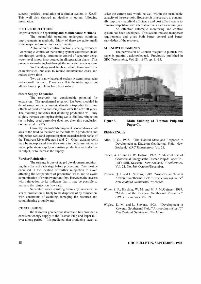
Figure 3. Main building o f Tasman Pulp andPaper Co.
REFERENCES
Allis, R. G., 1997. “The Natural State and Response toDevelopment at Kawerau Geothermal Field, NewZealand,” GRC Transactions , Vo. 21.
Carter, A. C. and G. W. Hotson, 1992. “Industrial Use of Geothermal Energy at the Tasman Pulp & Paper Co.,Ltd’s Mill, Kawerau, New Zealand,” Geothermics ,Vol. 21, No. 5/6, October/December.
Robson, Q. J. and L. Stevens, 1989. “Anti-Scalant Trial atKawerau Geothermal Field,” Proceedings of the 11 th
New Zealand Geothermal Workshop .
White, S. P.; Kissling, W. M. and M. J. McGuiness, 1997.“Models of the Kawerau Geothermal Reservoir,”GRC Transactions , Vol. 21.
Wigley, D. M. and L. Stevens, 1993. “Development inKawerau Geothermal Field,” Proceedings of the 15 th
New Zealand Geothermal Workshop.
GHC BULLETIN, SEPTEMBER 1998
8/8/2019 September 1998 Geo-Heat Center Quarterly Bulletin
http://slidepdf.com/reader/full/september-1998-geo-heat-center-quarterly-bulletin 21/40
TIMBER DRYING AT KAWERAU
John W. ScottDirector, Tekwood Ltd.Taradale, New Zealand
John W. LundGeo-Heat Center
BACKGROUNDTraditional methods of drying timber in New Zealand
were largely reliant on stacking the sawn timber in layers withspacing pieces outdoors, and letting the sun and wind do thework over a period of a few weeks in summer and muchlonger, if ever in winter. Some timber was pre-dried in theopen air and then “topped-off:, i.e. brought down to therequired moisture content in the controlled atmosphere of adrying kiln. Older types of drying kilns in the USA were of the “wigwam” or conical type.
This procedure had certain limitations: (1) variabilityof moisture content from top to bottom and side to sidedepending upon the exposure, (2) the temperature in the kilnand the final moisture content of the lumber could not be wellcontrolled in the older type drying kilns, (3) sun checkingwould occur at the top of the stack in the open air, and wideboards would curl or twist, and (4) increased handling costand prolonged drying period requiring material to be heldlonger in inventory.
About 40 years ago, a number of the larger sawmillsbegan building timber drying kilns. These were typicallyenclosures constructed from brick, concrete and concretemasonry and would accommodate 20 to 50 m 3 of stackedtimber. The enclosures or chambers were heated by steam andheat exchangers. Operating temperatures were low by today’sstandards typically 60 to 70 oC (80 oC maximum) whichresulted in timber taking up to 2-3 weeks to dry from greensawn state.
At that time, the timber resources was mostly Nativespecies and the slow drying process was ideally suited as itallowed the moisture to be extracted without subjecting thetimber to cell damage and stress. About 20 years ago thetechnology developed with the introduction of “dehumidifying” drying processes which basically usedreverse cycle refrigeration techniques similar to airconditioning to removed the moisture from the timber.
The percentage of timber dried from the total sawnwas relatively small and demand for the dried project wassuch that a premium could be charged which made the dryingprocess a very profitable business. It was obviously thequickest and simplest way to add value to the timber, and stillis today.
RADIATA PINEWith the rapid decline in the availability of Native
timber species and a large plantation grown Radiata Pine
GHC BULLETIN, SEPTEMBER 1998
resource becoming available, the drying process needed tochange. Radiata Pine has quite different characteristics to thenative species being lower density full of knots and inparticular having a very high moisture content (up to 130% byweight). New Zealand’s timber industry is now dependent onthis new resource.
The Radiata Pine, however, has some seriousdisadvantages compared to most other timbers used in similarsituations: (1) it is of low density and variable in densitythrough the log, (2) it has very high moisture content whenharvested, (3) it is of relatively low strength, and (4) it issubject to fungal and insect attack if not treated.
The Forest Research Institute have developedtechniques and processes which solve many of the problemslisted above, and are list in order as follows: (1) grading of sawn timber, (b) kiln drying schedules, (c) measuring andbeing able to guarantee strength, and (4) a number of preventative treatment processes. The most important singlefactor is kiln drying the timber in order to be able to supply acompletely predictable product.
KILN DETAILSThe two main reason for drying lumber is to set the
sap and prevent warping. The sap usually sets at 57 to 60 oCand warping is prevented by establishing uniform moisturecontent through the thickness of the wood, which is bestachieved in a kiln. The drying rate varies with the species of wood and decreases (time increases) with thicker sizes.
Kiln drying techniques have developed to the extentthat different drying regimes are followed depending on theend use of the timber. For timber used in structuralapplications the appearance is not important provided that thetimber is strong straight and stable. These parameters can beachieved by firstly grading the timber correctly then drying atelevated temperatures which allow drying in 24 hours or less.Often some form of timber treatment process will followdrying.
For timber that is required to further processing intoproducts such as flooring, cladding joinery and furniture thetimber must be dried in a way that precludes apparent defectswhich detract from appearance. For finger jointing andlaminating to produce building components it is of criticalimportance to have timber dried accurately with moisturecontent varying between pieces by no more than ±1%.
In basic terms a timber drying kiln is simply a largeoven which can be heated up and have the enclosed heated air
19
8/8/2019 September 1998 Geo-Heat Center Quarterly Bulletin
http://slidepdf.com/reader/full/september-1998-geo-heat-center-quarterly-bulletin 22/40
circulated to draw the moisture from the timber and exhaust itto the atmosphere. By far the most popular method of providing the energy in recent times has been to supply hotwater at high pressure and temperature to an enclosed systemwith heat exchangers in the kilns and fans distributing the airat velocities ranging from 5 m/s to 8 m/s and with kilntemperatures ranging from 80 to 140 oC. The operation of thekilns can be completely automatic. Steam can also be used asa heat source. Using geothermal energy, the cost is estimated
to be between NZ$2.00 to NZ$4.00 per m3
(US$1.00 to 2.00).This is usually less than half the cost of other fuel sources,however, geothermal energy is not available everywhere.
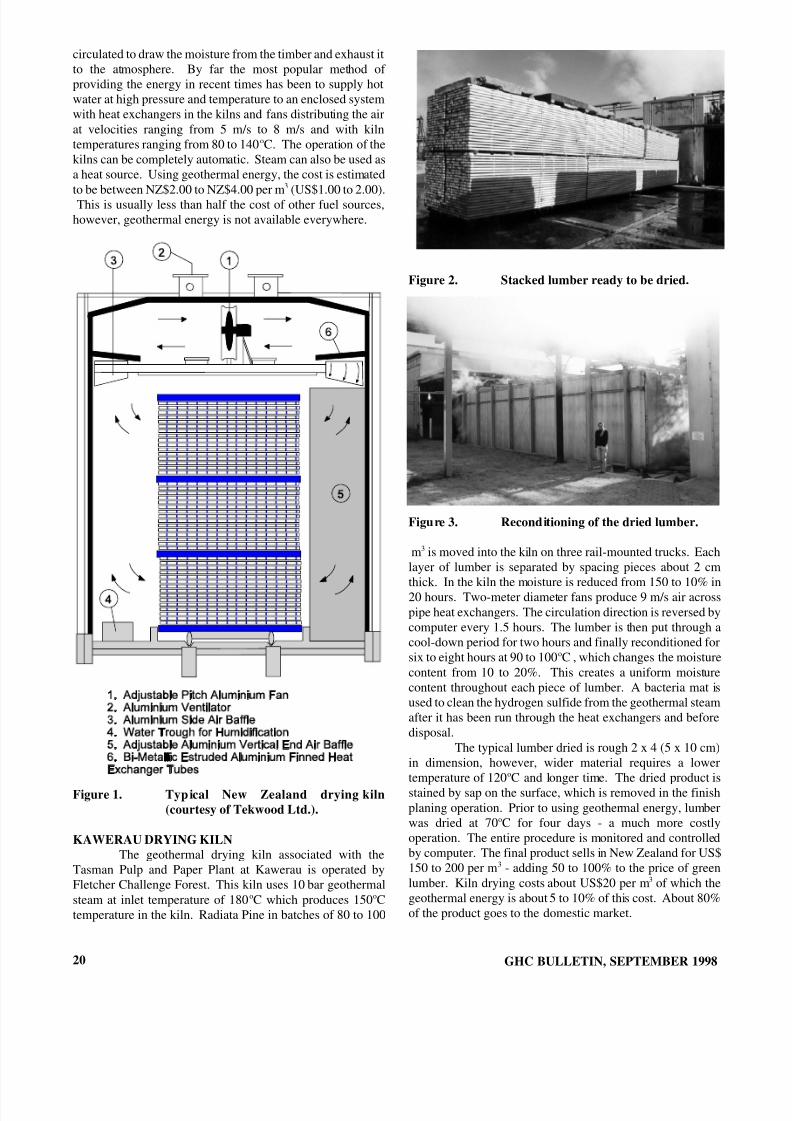
Figure 1. Typ ical New Zealand drying kiln(courtesy of Tekwood Ltd.).
KAWERAU DRYING KILNThe geothermal drying kiln associated with the
Tasman Pulp and Paper Plant at Kawerau is operated byFletcher Challenge Forest. This kiln uses 10 bar geothermalsteam at inlet temperature of 180 oC which produces 150 oCtemperature in the kiln. Radiata Pine in batches of 80 to 100
20
Figure 2. Stacked lumber ready to be dried.
Figure 3. Reconditioning of the dried lumber.
m3 is moved into the kiln on three rail-mounted trucks. Eachlayer of lumber is separated by spacing pieces about 2 cmthick. In the kiln the moisture is reduced from 150 to 10% in20 hours. Two-meter diameter fans produce 9 m/s air acrosspipe heat exchangers. The circulation direction is reversed bycomputer every 1.5 hours. The lumber is then put through acool-down period for two hours and finally reconditioned forsix to eight hours at 90 to 100 oC , which changes the moisturecontent from 10 to 20%. This creates a uniform moisturecontent throughout each piece of lumber. A bacteria mat isused to clean the hydrogen sulfide from the geothermal steamafter it has been run through the heat exchangers and beforedisposal.
The typical lumber dried is rough 2 x 4 (5 x 10 cm)in dimension, however, wider material requires a lowertemperature of 120 oC and longer time. The dried product isstained by sap on the surface, which is removed in the finishplaning operation. Prior to using geothermal energy, lumberwas dried at 70 oC for four days - a much more costlyoperation. The entire procedure is monitored and controlledby computer. The final product sells in New Zealand for US$150 to 200 per m 3 - adding 50 to 100% to the price of greenlumber. Kiln drying costs about US$20 per m 3 of which thegeothermal energy is about 5 to 10% of this cost. About 80%of the product goes to the domestic market.
GHC BULLETIN, SEPTEMBER 1998

8/8/2019 September 1998 Geo-Heat Center Quarterly Bulletin
http://slidepdf.com/reader/full/september-1998-geo-heat-center-quarterly-bulletin 23/40
GEOTHERMALGREENHOUSES AT KAWERAU
Michael Dunstall (1) and Brian Foster (2)
(1) Geothermal Institute, The University of Auckland, Private Bag 92019, Auckland, New Zealand(2) Geothermal Greenhouses, Ltd., PO Box 41, Kawerau, New Zealand
INTRODUCTION Geothermal Greenhouses Ltd was established in
1982 by a small group of Tasman Pulp and Paper Companyemployees who saw an opportunity to utilise geothermalsteam available in the Kawerau geothermal field. Theoperation produces capsicum (bell pepper) for local andexport markets and is located entirely within the production steamfield at Kawerau. Heating for the greenhouses is
provided by a small flow of geothermal steam taken from atwo-phase pipeline, fed by several deep geothermal wells.
The greenhouse operation is small, with a permanent
staff of five, including a share holding manager. Marketingand packing of the crop is handled by a separate company.Total greenhouse area is 5250 m 2, consisting of 3600 m 2 in an early timber frame fan ventilated single plastic covereddesign built in 1982, and an area of 1650 m 2 in a modern fan ventilated twin skin steel and aluminium framed greenhousebuilt in 1994. Heating requirements are relatively highcompared to other greenhouses in New Zealand, due to thehigh minimum night and day temperatures needed for thecrop grown, and the cool Kawerau climate.
The primary utilisation of geothermal steam at Kawerau is as a heat source for the Tasman Pulp and PaperCompany mill, which uses approximately 300 tonnes/hour of
steam, mainly to generate clean steam for paper drying.High temperature lumber drying kilns are also supplied withgeothermal steam at the same site. Steam supplied to thegreenhouse is a very small part of total steam production.Although the greenhouse is independently owned andoperated it would not exist without the paper mill, sincesteam production would not be viable for the greenhouseoperation alone. Without geothermal heating the climate at Kawerau would preclude heated greenhouse operation, asfreezing night time temperatures occur during winter.Geothermal heating has allowed the high sunshine levelsfound in the Bay of Plenty area to be used to advantagewithout the problem of frost being a major factor.
Carbon dioxide, which is a very effective growthstimulant for plants, is used in the greenhouses. Studies haveshown that as CO 2 concentration is increased from a normallevel of 300 ppm (mmol/kmol) to levels of approximately1000 ppm crop yields may increase by up to 30% (Ullmann,1989). Bottled carbon dioxide is utilised at a rate of about 50kg per day, to provide CO 2 levels of 800 mg/kg when thegreenhouse is closed and 300 to 350 mg/kg whilst venting.In England and the Netherlands CO 2 levels of 1000 mg/kg
GHC BULLETIN, SEPTEMBER 1998
are often used (Ullmann, 1989) and similar concentrations aredesired at Kawerau, but current costs of 0.60 NZ$/kg forbottled CO 2 are too high.
Geothermal greenhouse heating offers an opportunityfor utilisation of the carbon dioxide present in the geothermalfluid. The main difficulty is that plants react adversely tohydrogen sulphide which is mixed with the CO 2 in the steam.Even very low H 2S concentrations of 0.03 mg/kg can have
negative effects on the growth of plants (National ResearchCouncil, 1979). Therefore, purification of the available CO 2 would be required before it could be used in the greenhouses.
Some work on this subject was presented by Dunstall andGraeber (1997).
GREENHOUSE CONSTRUCTION Two fan ventilated greenhouses are currently in use
in Kawerau. The older greenhouse, built in 1982, covers3600m2 and is timber framed with a single plastic cover.This greenhouse provides a relatively large night time heat load, as capsicum has a relatively high temperature require-ment (Table 1).
Figure 1. Older greenhouse with Capsicum (greenpeppers) plants and heating pipes(bottom one is condensate return)
The second greenhouse covers an area of 1650 m 2,and is a modern design fan ventilated twin skin stainless steeland aluminum framed greenhouse built in 1994. The twin skin dramatically lowers heat load requirements in thisgreenhouse, compared to the older design.
21

8/8/2019 September 1998 Geo-Heat Center Quarterly Bulletin
http://slidepdf.com/reader/full/september-1998-geo-heat-center-quarterly-bulletin 24/40
Table 1. Minimum growing temperatures forseveral greenhouse crops
Crop TypeMinimum NightTemperature ( oC)
Minimum DayTemperature ( oC)
Tomato 15 18Capsicum 18 20Aubergine 20 25Roses 16 18
Carnation 10 18* Higher temperatures may be required with high CO 2, humidityand light levels.
Figure 2. New greenhouse with manager, BrianFoster.
CROP AND GROWING SYSTEM Geothermal Greenhouses grows its capsicum crop in
a specially graded pumice, fertilised and watered using ahydroponics method. The irrigation system is controlled bysolar sensors, dispensing nutrients at a rate dependent on the
uptake rate in the plants. Mature plants grow to a height of approximately 3.5m, at which point they are discarded andthe growing process is restarted from new seedlings.
A high quality crop is grown, with a crop yield of over 20kg/m 2 annually for red and yellow capsicums, and30kg/m 2 annually for green capsicums. This compares verywell with a target figure of 25kg/m 2 annually, given in 1994by the New Zealand Ministry of Agriculture and Fisheries.
The greenhouse climate is controlled using aMAXSYS greenhouse computer control system, with humid-ity control and a CO 2 enrichment system. The MAXSYSsystem is a commercial crop management system designedfor New Zealand climate, and gives crop production rates
which are about twice that of traditional type greenhouses.
HEATING SYSTEM AND CONTROLSSteam for the greenhouse is supplied from the a two
phase line fed by several wells in the north eastern part of thebore field. The primary separator for this two phase fluid issome 500m distant, so a small separator mounted to one sideof the two phase line is used. Flows to the greenhouse arequite low, so steam can be tapped from this small separatorand the remaining water returned to the two-phase line. The
22
steam supply is at 270 oC and a pressure of 15 bar in the two phase line, but a pressure control valve reduces this to 5 barin the 50mm greenhouse steam supply line, which is buried in a shallow trench. Estimated annual energy usage is about 700,000 kWh, with an energy cost of about NZ$4900. The
unit energy cost is therefore NZ$0.007/kWh, or about NZ$5.50 per tonne of steam. The steam flow is not metered;instead a flat rate is charged each year, based on historicalcondensate flow data.
Figure 3. Separator on two-phase line withpressure control valve.
Fast growing crops in heated greenhouses are veryvulnerable to a loss of heating, so a backup supply isrequired. At Kawerau, several wells supply the two-phaseline so a shut down of any individual well for maintenancedoes not affect the greenhouse. The most vulnerable part of the system is probably the short buried steam supply linefrom the pressure control valve to the greenhouse. To date,this has not caused any problems.
The pressure control valve maintains a constant 5bar inlet pressure to the system. Motorised valves connectedto temperature controllers in the greenhouse then determinethe flow of steam admitted to distribution headers, which in turn supply a network of 25mm diameter heating pipes.Condensate and residual steam from the heating pipes flow toatmosphere. The black steel heating pipes are installed abovethe crop, supplying heat to the air and radiant energy to the
plants. Wet and dry bulb sensors (PT100) are used for humi-dity and temperature control as part of the MAXSYS system.
Data is not available for the original costs of theheating system, but based on data collected during the 1994
upgrade of the 1650m 2 unit, installed costs are estimated at
NZ$8.30 per m 2, including pressure control valves, tempera-ture control valves, pipework and installation costs. Totalcosts for the heating system are therefore around NZ$44,000capital cost + NZ$4,900 annual running cost. Assuming a20 year equipment life the discounted cost (12% discount rate) is NZ$0.036/kWh ($0.029 equipment + $0.007energy). Some comparison with other fuels is then possible.
Heating a similar greenhouse with electricity in theFranklin district (an intensive crop growing area) would cost
GHC BULLETIN, SEPTEMBER 1998

8/8/2019 September 1998 Geo-Heat Center Quarterly Bulletin
http://slidepdf.com/reader/full/september-1998-geo-heat-center-quarterly-bulletin 25/40
about 11c/kWh (7c energy + 4c installation), based on aheating requirement in Franklin of 110 kWh/m 2 annually.compared to 133 kWh/m 2 annually in Kawerau. This is a$38,000 yearly saving to the geothermal greenhouse, but at least part of this saving is offset by transportation costs, asKawerau is much further from major domestic markets and
ports of export.Most heat is lost from greenhouses by air leakage
and wind effects due to poor construction. Modern plastic
covered greenhouses may use as little as 30% of the heat needed for an older glass covered greenhouse. Typical heat loss rates at Kawerau are 3.5W/m 2K in plastic greenhousescompared to 12W/m 2K in glass covered greenhouses. Thenew twin-skin plastic greenhouse achieves these low heat losses without loss of solar light transmission required for
plant growth. Heat loss rates impact heavily on greenhouse profitability.
OPTIMUM GROWING CONDITIONSPlants grow and develop most efficiently when the
environment is controlled with specific day and night temperatures. Generally, higher crop yields are obtained at higher temperatures and the cost of supplying additionalenergy for heating must be balanced against the increase in yield expected. Low marginal cost forms of energy, such asgeothermal, give higher optimum temperature conditions than high marginal cost system such as electricity.
Most crops respond to 24 hour mean temperatures, provided the variation in temperature over that time is not tooextreme. This means that electrically heated greenhouses can tolerate lower temperatures during times of high tariff, andoperate at higher temperatures during low tariff times tocompensate. The Kawerau greenhouse is not constrained in this manner, but could be operated in this way if the steamsupply shared with another operation was critical at certain times of the day.
Humidity control has a very significant beneficialeffect and often it is humidity control, rather than dry bulbtemperature, which controls greenhouse conditions. Fungusdisease control is highly dependent on the humidity level.Continuous air movement through the leaves of the plants isalso important to control fungus, by eliminating moisturefrom the leaf surface. The reduction in cost and risk associ-ated with chemical sprays substantially offset the additionalexpense involved in a more sophisticated control system.Improving fruit quality and yield result in increased
profitability.
Air leakage rates have a severe impact on economicswhen CO 2 enrichment and humidity control are used, sincethese factors are much more expensive to control and providethan dry bulb temperature. At Kawerau the annual cost of
providing bottled CO 2 is higher than the geothermal energycost. Best growth rates are achieved when humidity, CO 2 enrichment, and temperature are all controlled in a low lossgreenhouse. High temperature only translates to high growthrates if the level of CO 2. is also high. Without additionalCO2 higher temperatures will stress the plants.
GHC BULLETIN, SEPTEMBER 1998
It is interesting to note that the steam supplied to thegreenhouse each year for heating purposes contains almost exactly the quantity of bottled CO 2 used each year(Geothermal & Nuclear Sciences, 1992). With appropriatetreatment, the geothermal steam might ultimately be asvaluable for its CO 2 contribution as for its heating value.
OTHER FACTORS AND FUTURE TRENDS A number of proposals for geothermal heating of
New Zealand greenhouses have been studied over the past 15years or so. In most cases the relatively mild New Zealandclimate has greatly reduced the advantage obtained fromgeothermal heating. High capital costs are difficult torecover when energy costs are quite low. In addition, thegeothermal areas are further from markets than traditionalgreenhouse areas and transport costs have been high.
However, the size of new greenhouse developmentshas increased dramatically in recent times, from a typical sizeof 2000m 2 to 10 to 50 times larger. The heating demand hasconsequently risen by a similar factor, as these new export oriented units are developed. With falling transport costs,and with more intensive heating and crop production rates,geothermal greenhouse heating is becoming more attractive.
The use of geothermal carbon dioxide for growthstimulation of plants might be possible if a purification
process is used to reduce the initial hydrogen sulfide content.This would greatly increase the attractiveness of geothermal
energy in greenhouses where a steam source is available.The CO 2 could be worth as much as the energy in theKawerau operation. However, a cheap purification process isneeded.
REFERENCES
Dunstall, M. G. and G. Graeber, 1997. Geothermal Car-bon Dioxide for Use in Greenhouses , Geo-Heat Center Quarterly Bulletin, Vol. 18, No. 1,Klamath Falls, OR, pp. 8-13.
Geothermal & Nuclear Sciences, Ltd., June and July 1992A Gas Analysis of Steam at Tasman Lumber,Kawerau, New Zealand.
National Research Council, 1979. Hydrogen Sulfide, Sub-committee on Hydrogen Sulfide, Committee on
Medical and Biologic Effects of Environmental Pollutants, University Park Press, Baltimore,
MD.Ullmann, 1989. A Carbon Dioxide, @ Ullmann =s Encyclo-
pedia of Industrial Chemistry, 5 th Ed., Vol. A5,VCH Verlagsgesellschaft, Weinheim, NY, pp.165-183.
23
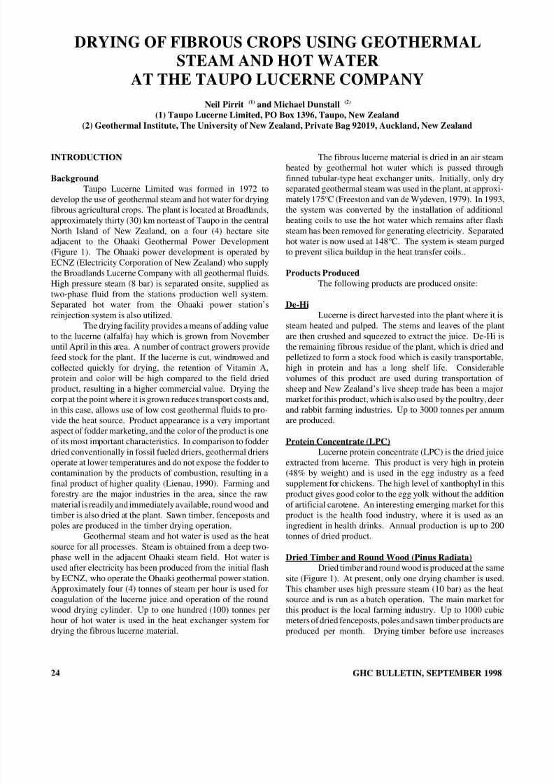
8/8/2019 September 1998 Geo-Heat Center Quarterly Bulletin
http://slidepdf.com/reader/full/september-1998-geo-heat-center-quarterly-bulletin 26/40
DRYING OF FIBROUS CROPS USING GEOTHERMALSTEAM AND HOT WATER
AT THE TAUPO LUCERNE COMPANYNeil Pirrit (1) and Michael Dunstall (2)
(1) Taupo Lucerne Limited, PO Box 1396, Taupo, New Zealand(2) Geothermal Institute, The University of New Zealand, Private Bag 92019, Auckland, New Zealand
INTRODUCTION
BackgroundTaupo Lucerne Limited was formed in 1972 to
develop the use of geothermal steam and hot water for dryingfibrous agricultural crops. The plant is located at Broadlands,approximately thirty (30) km norteast of Taupo in the centralNorth Island of New Zealand, on a four (4) hectare siteadjacent to the Ohaaki Geothermal Power Development(Figure 1). The Ohaaki power development is operated byECNZ (Electricity Corporation of New Zealand) who supply
the Broadlands Lucerne Company with all geothermal fluids.High pressure steam (8 bar) is separated onsite, supplied astwo-phase fluid from the stations production well system.Separated hot water from the Ohaaki power station’sreinjection system is also utilized.
The drying facility provides a means of adding valueto the lucerne (alfalfa) hay which is grown from Novemberuntil April in this area. A number of contract growers providefeed stock for the plant. If the lucerne is cut, windrowed andcollected quickly for drying, the retention of Vitamin A,protein and color will be high compared to the field driedproduct, resulting in a higher commercial value. Drying thecorp at the point where it is grown reduces transport costs and,
in this case, allows use of low cost geothermal fluids to pro-vide the heat source. Product appearance is a very importantaspect of fodder marketing, and the color of the product is oneof its most important characteristics. In comparison to fodderdried conventionally in fossil fueled driers, geothermal driersoperate at lower temperatures and do not expose the fodder tocontamination by the products of combustion, resulting in afinal product of higher quality (Lienau, 1990). Farming andforestry are the major industries in the area, since the rawmaterial is readily and immediately available, round wood andtimber is also dried at the plant. Sawn timber, fenceposts andpoles are produced in the timber drying operation.
Geothermal steam and hot water is used as the heat
source for all processes. Steam is obtained from a deep two-phase well in the adjacent Ohaaki steam field. Hot water isused after electricity has been produced from the initial flashby ECNZ, who operate the Ohaaki geothermal power station.Approximately four (4) tonnes of steam per hour is used forcoagulation of the lucerne juice and operation of the roundwood drying cylinder. Up to one hundred (100) tonnes perhour of hot water is used in the heat exchanger system fordrying the fibrous lucerne material.
24
The fibrous lucerne material is dried in an air steamheated by geothermal hot water which is passed throughfinned tubular-type heat exchanger units. Initially, only dryseparated geothermal steam was used in the plant, at approxi-mately 175 oC (Freeston and van de Wydeven, 1979). In 1993,the system was converted by the installation of additionalheating coils to use the hot water which remains after flashsteam has been removed for generating electricity. Separatedhot water is now used at 148 oC. The system is steam purgedto prevent silica buildup in the heat transfer coils..
Products ProducedThe following products are produced onsite:
De-HiLucerne is direct harvested into the plant where it is
steam heated and pulped. The stems and leaves of the plantare then crushed and squeezed to extract the juice. De-Hi isthe remaining fibrous residue of the plant, which is dried andpelletized to form a stock food which is easily transportable,high in protein and has a long shelf life. Considerablevolumes of this product are used during transportation of sheep and New Zealand’s live sheep trade has been a majormarket for this product, which is also used by the poultry, deer
and rabbit farming industries. Up to 3000 tonnes per annumare produced.
Protein Concentrate (LPC)Lucerne protein concentrate (LPC) is the dried juice
extracted from lucerne. This product is very high in protein(48% by weight) and is used in the egg industry as a feedsupplement for chickens. The high level of xanthophyl in thisproduct gives good color to the egg yolk without the additionof artificial carotene. An interesting emerging market for thisproduct is the health food industry, where it is used as aningredient in health drinks. Annual production is up to 200tonnes of dried product.
Dried Timber and Round Wood (Pinus Radiata) Dried timber and round wood is produced at the same
site (Figure 1). At present, only one drying chamber is used.This chamber uses high pressure steam (10 bar) as the heatsource and is run as a batch operation. The main market forthis product is the local farming industry. Up to 1000 cubicmeters of dried fenceposts, poles and sawn timber products areproduced per month. Drying timber before use increases
GHC BULLETIN, SEPTEMBER 1998
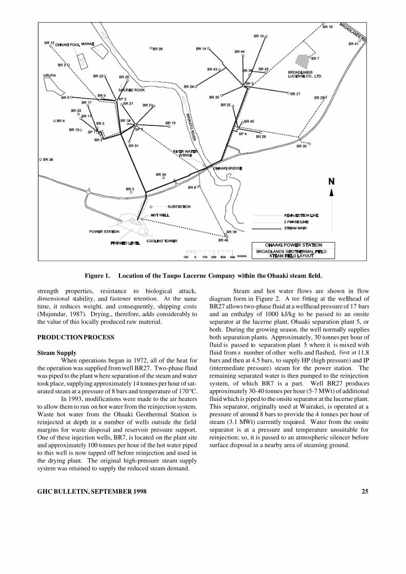
8/8/2019 September 1998 Geo-Heat Center Quarterly Bulletin
http://slidepdf.com/reader/full/september-1998-geo-heat-center-quarterly-bulletin 27/40
Figure 1. Location of the Taupo Lucerne Company within the Ohaaki steam field.
strength properties, resistance to biological attack,
dimensional stability, and fastener retention. At the sametime, it reduces weight, and consequently, shipping costs(Mujundar, 1987). Drying,, therefore, adds considerably tothe value of this locally produced raw material.
PRODUCTION PROCESS
Steam SupplyWhen operations began in 1972, all of the heat for
the operation was supplied from well BR27. Two-phase fluidwas piped to the plant where separation of the steam and watertook place, supplying approximately 14 tonnes per hour of sat-urated steam at a pressure of 8 bars and temperature of 170 oC.
In 1993, modifications were made to the air heatersto allow them to run on hot water from the reinjection system.Waste hot water from the Ohaaki Geothermal Station isreinjected at depth in a number of wells outside the fieldmargins for waste disposal and reservoir pressure support.One of these injection wells, BR7, is located on the plant siteand approximately 100 tonnes per hour of the hot water pipedto this well is now tapped off before reinjection and used inthe drying plant. The original high-pressure steam supplysystem was retained to supply the reduced steam demand.
GHC BULLETIN, SEPTEMBER 1998
Steam and hot water flows are shown in flow
diagram form in Figure 2. A tee fitting at the wellhead of BR27 allows two-phase fluid at a wellhead pressure of 17 barsand an enthalpy of 1000 kJ/kg to be passed to an onsiteseparator at the lucerne plant, Ohaaki separation plant 5, orboth. During the growing season, the well normally suppliesboth separation plants. Approximately, 30 tonnes per hour of fluid is passed to separation plant 5 where it is mixed withfluid from a number of other wells and flashed, first at 11.8bars and then at 4.5 bars, to supply HP (high pressure) and IP(intermediate pressure) steam for the power station. Theremaining separated water is then pumped to the reinjectionsystem, of which BR7 is a part. Well BR27 producesapproximately 30-40 tonnes per hour (5-7 MWt) of additionalfluid which is piped to the onsite separator at the lucerne plant.This separator, originally used at Wairakei, is operated at apressure of around 8 bars to provide the 4 tonnes per hour of steam (3.1 MWt) currently required. Water from the onsiteseparator is at a pressure and temperature unsuitable forreinjection; so, it is passed to an atmospheric silencer beforesurface disposal in a nearby area of steaming ground.
25
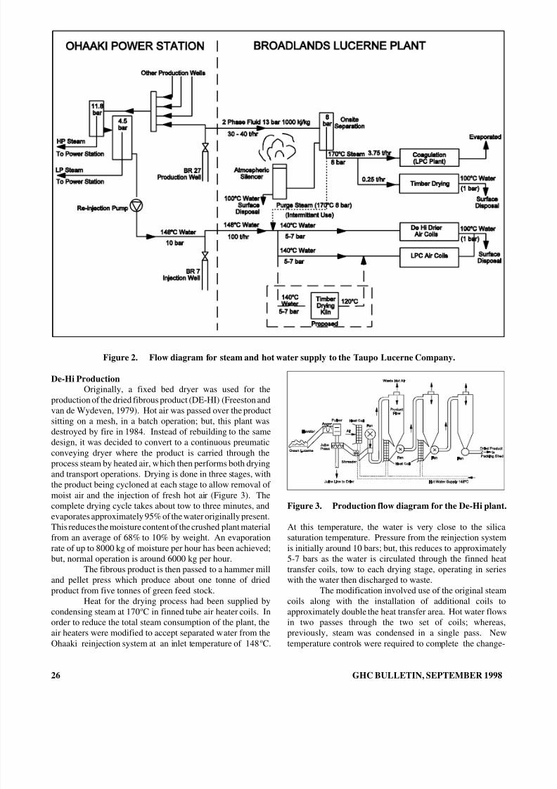
8/8/2019 September 1998 Geo-Heat Center Quarterly Bulletin
http://slidepdf.com/reader/full/september-1998-geo-heat-center-quarterly-bulletin 28/40
Figure 2. Flow diagram for steam and hot water supply to the Taupo Lucerne Company.
De-Hi ProductionOriginally, a fixed bed dryer was used for the
production of the dried fibrous product (DE-HI) (Freeston and
van de Wydeven, 1979). Hot air was passed over the productsitting on a mesh, in a batch operation; but, this plant wasdestroyed by fire in 1984. Instead of rebuilding to the samedesign, it was decided to convert to a continuous preumaticconveying dryer where the product is carried through theprocess steam by heated air, which then performs both dryingand transport operations. Drying is done in three stages, withthe product being cycloned at each stage to allow removal of moist air and the injection of fresh hot air (Figure 3). Thecomplete drying cycle takes about tow to three minutes, andevaporates approximately 95% of the water originally present.This reduces the moisture content of the crushed plant materialfrom an average of 68% to 10% by weight. An evaporationrate of up to 8000 kg of moisture per hour has been achieved;but, normal operation is around 6000 kg per hour.
The fibrous product is then passed to a hammer milland pellet press which produce about one tonne of driedproduct from five tonnes of green feed stock.
Heat for the drying process had been supplied bycondensing steam at 170 oC in finned tube air heater coils. Inorder to reduce the total steam consumption of the plant, theair heaters were modified to accept separated water from theOhaaki reinjection system at an inlet temperature of 148 oC.
26
Figure 3. Production flow diagram for the De-Hi plant.
At this temperature, the water is very close to the silicasaturation temperature. Pressure from the reinjection systemis initially around 10 bars; but, this reduces to approximately5-7 bars as the water is circulated through the finned heattransfer coils, tow to each drying stage, operating in serieswith the water then discharged to waste.
The modification involved use of the original steamcoils along with the installation of additional coils toapproximately double the heat transfer area. Hot water flowsin two passes through the two set of coils; whereas,previously, steam was condensed in a single pass. Newtemperature controls were required to complete the change-
GHC BULLETIN, SEPTEMBER 1998
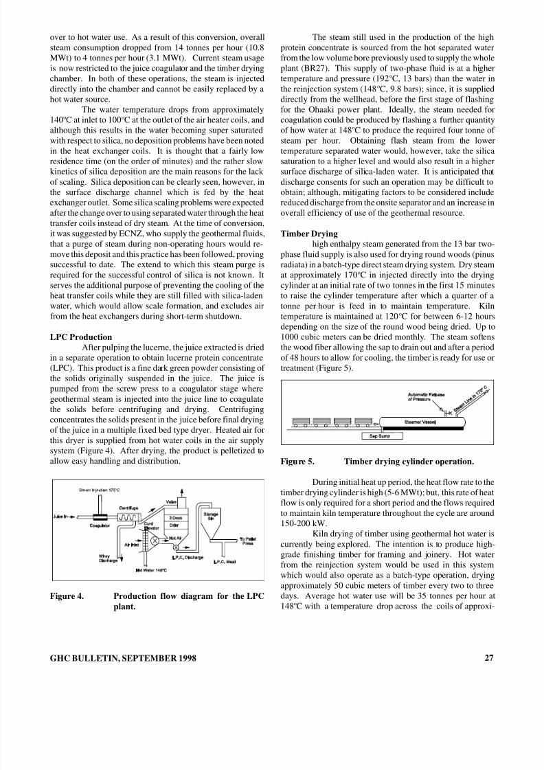
8/8/2019 September 1998 Geo-Heat Center Quarterly Bulletin
http://slidepdf.com/reader/full/september-1998-geo-heat-center-quarterly-bulletin 29/40
over to hot water use. As a result of this conversion, overallsteam consumption dropped from 14 tonnes per hour (10.8MWt) to 4 tonnes per hour (3.1 MWt). Current steam usageis now restricted to the juice coagulator and the timber dryingchamber. In both of these operations, the steam is injecteddirectly into the chamber and cannot be easily replaced by ahot water source.
The water temperature drops from approximately140 oC at inlet to 100 oC at the outlet of the air heater coils, andalthough this results in the water becoming super saturatedwith respect to silica, no deposition problems have been notedin the heat exchanger coils. It is thought that a fairly lowresidence time (on the order of minutes) and the rather slowkinetics of silica deposition are the main reasons for the lack of scaling. Silica deposition can be clearly seen, however, inthe surface discharge channel which is fed by the heatexchanger outlet. Some silica scaling problems were expectedafter the change over to using separated water through the heattransfer coils instead of dry steam. At the time of conversion,it was suggested by ECNZ, who supply the geothermal fluids,that a purge of steam during non-operating hours would re-move this deposit and this practice has been followed, provingsuccessful to date. The extend to which this steam purge isrequired for the successful control of silica is not known. Itserves the additional purpose of preventing the cooling of theheat transfer coils while they are still filled with silica-ladenwater, which would allow scale formation, and excludes airfrom the heat exchangers during short-term shutdown.
LPC ProductionAfter pulping the lucerne, the juice extracted is dried
in a separate operation to obtain lucerne protein concentrate(LPC). This product is a fine dark green powder consisting of the solids originally suspended in the juice. The juice ispumped from the screw press to a coagulator stage wheregeothermal steam is injected into the juice line to coagulatethe solids before centrifuging and drying. Centrifugingconcentrates the solids present in the juice before final dryingof the juice in a multiple fixed bed type dryer. Heated air forthis dryer is supplied from hot water coils in the air supplysystem (Figure 4). After drying, the product is pelletized toallow easy handling and distribution.
Figure 4. Production flow diagram for the LPCplant.
GHC BULLETIN, SEPTEMBER 1998
The steam still used in the production of the highprotein concentrate is sourced from the hot separated waterfrom the low volume bore previously used to supply the wholeplant (BR27). This supply of two-phase fluid is at a highertemperature and pressure (192 oC, 13 bars) than the water inthe reinjection system (148 oC, 9.8 bars); since, it is supplieddirectly from the wellhead, before the first stage of flashingfor the Ohaaki power plant. Ideally, the steam needed forcoagulation could be produced by flashing a further quantityof how water at 148 oC to produce the required four tonne of steam per hour. Obtaining flash steam from the lowertemperature separated water would, however, take the silicasaturation to a higher level and would also result in a highersurface discharge of silica-laden water. It is anticipated thatdischarge consents for such an operation may be difficult toobtain; although, mitigating factors to be considered includereduced discharge from the onsite separator and an increase inoverall efficiency of use of the geothermal resource.
Timber Dryinghigh enthalpy steam generated from the 13 bar two-
phase fluid supply is also used for drying round woods (pinusradiata) in a batch-type direct steam drying system. Dry steamat approximately 170 oC in injected directly into the dryingcylinder at an initial rate of two tonnes in the first 15 minutesto raise the cylinder temperature after which a quarter of atonne per hour is feed in to maintain temperature. Kilntemperature is maintained at 120 oC for between 6-12 hoursdepending on the size of the round wood being dried. Up to1000 cubic meters can be dried monthly. The steam softensthe wood fiber allowing the sap to drain out and after a periodof 48 hours to allow for cooling, the timber is ready for use ortreatment (Figure 5).
Figure 5. Timber drying cylinder operation.
During initial heat up period, the heat flow rate to thetimber drying cylinder is high (5-6 MWt); but, this rate of heatflow is only required for a short period and the flows requiredto maintain kiln temperature throughout the cycle are around150-200 kW.
Kiln drying of timber using geothermal hot water iscurrently being explored. The intention is to produce high-grade finishing timber for framing and joinery. Hot waterfrom the reinjection system would be used in this systemwhich would also operate as a batch-type operation, dryingapproximately 50 cubic meters of timber every two to threedays. Average hot water use will be 35 tonnes per hour at148 oC with a temperature drop across the coils of approxi-
27

8/8/2019 September 1998 Geo-Heat Center Quarterly Bulletin
http://slidepdf.com/reader/full/september-1998-geo-heat-center-quarterly-bulletin 30/40
mately 20 oC to meet a heat load of around 800 kW. It isintended that, whenever possible, hot water discharged fromthe kiln air heaters will be piped for use in the lower tempera-ture heating coils of the lucerne drying plant to further use theresidual heat before discharge. Precautions to be taken againstsilica scaling will be similar to those used in the pneumaticconveying drying system. In view of previous experience, noserious scaling problems are anticipated. The main drawback of such a system is that the uniform kiln temperatures essentialfor the even drying of timber are difficult to obtain when heatis obtained by sensible cooling of hot water.
Both the domestic and export markets for high-quality dried pine products are expected to strengthen withgrowing acceptance of radiata pine as a finishing-gradetimber. The provision of a low-cost energy source,geothermal separated water (which is currently disposed of asa waste product), and the location of the Ohaaki power stationwithin plantation forests provide a strong basis for expansionin this area of operation.
OPERATIONThe presence of corrosive geothermal gases (H 2S)
means that electrical and control systems require protectionfrom atmospheric conditions, as do some items of exteriorpipe work. However, location of sensitive items of equipmentwithin onsite buildings and protective painting, and sheathingof outdoor equipment have eliminated most problems.Maintenance on the geothermal equipment is moderate, withthe main replacement items being operating valves. Incomparison to maintenance of material handling equipment,the geothermal equipment is not considered to have anyparticular maintenance difficulties. Fortunately, the gas levelsare low enough that it has not been necessary to providefiltered air to any of the electrical control systems.
The system is relatively simple to operate and onlyone operator is actually required to run the plant; although,two are used for safety reasons. Since the system wasdesigned to minimize fluid residence time within the heatexchangers, the plant has a short warm up period, andresponses to changes in load can be compensated for quitequickly. This allows considerable variations in product flowrate to be handled without loss in product quality. Six full-time staff manage and maintain the plant on an annual basis;but, during the growing season, the plant runs a double shift,providing seasonal work for another four workers. Growing,harvesting and transportation related to the lucerne plant alsoprovide employment during the growing season.
Because of the seasonal nature of the operation, theannual load factor for the plant is rather low. Annual energyuse is estimated at 14 TJ (excluding timber drying), and withan installed thermal capacity of 7 MW t, this gives at loadfactor of 6.5%. Calculating a sensible load factor for thetimber drying operation should be used. The maximum heatflow rate to the drying chamber is quite high (6 MWt); but, itis of such short duration (15 min. in a 12-hour cycle) that theusual design constraints do not apply. When the nominal kilnheat load is used, the plant capacity factor increases consider-
28
ably. The current timber drying operation uses just 200 kW;but, this is on an almost continuous basis. Annual energy usefor timber drying is about 6 TJ, giving a load factor of about9% for the operation overall. Expanding the plants capacityto dry timber, which is a twenty-four hour, year-roundoperations, has the potential to greatly improve the annualload factor. Currently, timber drying accounts for almost onethird of the annual energy use, while representing less than 3%of the plant thermal capacity.
CONCLUSIONSThe geothermal drying of agricultural crops at Taupo
Lucerne Limited has evolved from a proof of concept pilotplant into a successful commercial operation. Using the heatof the geothermal fluid directly in the process increases theefficiency of use of a natural resource. Recently,modifications have been made to existing heat exchangerequipment to enhance the inherent efficiency of the direct usesystem. By using separated water instead of saturated steamto provide a large proportion of the direct heat needs, thelucerne plant has provided a means of cascading a portion of the waste fluid available after generation of electricity.Cascading improves the overall efficiency of resource use atOhaaki by utilizing a waste product and any futuredevelopment will focus on using rejected water in this manner.
A further reduction in steam requirement could beobtained if the steam for the coagulator were suppled byflashing a quantity of water at 148 oC. Discharge consentswould have to be altered to allow this improvement, asadditional quantities of silica-laden water will be discharged.A reduced discharge from the onsite separator and animprovement in the efficiency of overall use of the Ohaakiresource are mitigating factors in such a proposal.
An expansion in the timber drying operation is themost likely form for future developments. Timber dryingoperations can achieve much higher load factors than lucernedrying, because the harvesting of timber is not seasonal inNew Zealand. A growing interest in the use of pnus radiata asa high-grade finishing timber is the main motivation toincrease the use of geothermal energy for timber drying in thecentral North Island.
REFERENCES
Freeston, D. H. and F. van de Wydeven, 1979. “MoreEfficient Use of Geothermal Heat in BroadlandsLucerne Company’ Drying Plant.” Proc. New
Zealand Geothermal Workshop (Part 2), Universityof Auckland, New Zealand, pp. 315-325.
Lienau, P. J., 1990. “Industrial Applications,” SmallGeothermal Resources - A Guide to Development and Utilization. M. H. Dickson and M. Fanelli(editors). UNITAR/UNDP, Rome, pp. 171-202.
Mujundar, A. S., 1987. Handbook of Industrial Drying ,Marcel Dekker Inc., New York.
GHC BULLETIN, SEPTEMBER 1998

8/8/2019 September 1998 Geo-Heat Center Quarterly Bulletin
http://slidepdf.com/reader/full/september-1998-geo-heat-center-quarterly-bulletin 31/40
PRAWN PARK - TAUPO, NEW ZEALANDJohn W. Lund
Geo-Heat Center
Richard Klein, DirectorPrawn Park
Taupo, New Zealand
New Zealand’s only freshwater prawn farm wasestablished in 1987 to take advantage of geothermal wasteheat from the Wairakei power generating field on NorthIsland. Since approximately 2000 tonnes (2200 tons) per yearof prawns are imported annually into New Zealand, themotivation was to try and capture some of this market with adomestic product.
Giant Malaysian Freshwater Prawns (MacrobrachiumRosenbergii) were imported from Malaysia in 1988. Half of these were lost in transit due to delays in lifting importrestrictions. A second import of 25 breeding males andfemales had to be quarantined for 15 months to assure thatthey were disease free. Also, officials required that if prawnsescaped into the adjacent Waikato River, they would not
survive and reproduce. It turns out that the prawns will die in14oC (57 oF) water, and since the river water is at 10 oC (50 oF),there was no chance of survival. Thus, a license was issued in1989 for the firm to start commercial production.
The original farm consisted of five outside poolstotaling one hectare (2.5 acres), and a small hatchery andnursery. Shortly, another four ponds were added to bring thetotal area to 2.5 ha (6.2 acres).
In 1993, the New Zealand Enterprise Board joinedNew Zealand Prawns Ltd., in partnership, and another 10ponds were developed bring the total pond surface area to 5.8ha (14.3 acres), with the entire facility occupying 10.2 ha(25.2 acres)(Figure1).
Figure 1. Prawn Park with Wairakei Power plant and Waikato River.
GHC BULLETIN, SEPTEMBER 1998 29

8/8/2019 September 1998 Geo-Heat Center Quarterly Bulletin
http://slidepdf.com/reader/full/september-1998-geo-heat-center-quarterly-bulletin 32/40
The present 19 ponds vary in size from 0.2 to 0.35 ha(0.5 to 9.9 acres) and have a depth of 1.0 to 1.2 m (3.3 to 3.9ft), providing a slope for ease of harvest. The length to widthratio of the pond surface is approximately 20:1. The sides aresloped for stability and the bottom material is composed of animpermeable volcanic ash that also stores nutrients for theprawns (Figure 2).
Figure 2. Detail of outdoor pond.
Ideally, the ponds should be kept at a temperature of 28oC (82 oF); but, presently, they are at 24 oC (75 oF) with atemperature variation from one end of the pond to the other of 1oC (2 oF). A temperature probe controls the flow of water intothe ponds and an aerator is used to obtain vertical mixing of the pond water. Without the vertical mixing, the pondbecomes temperature stratified, reducing the production of prawns.
Water for the ponds comes from two sources, theplate heat exchanger at 55 oC (131 oF) and river water at 10 oC(50oF). Water is circulated throughout the system from astorage and settling pond that is kept at 21 oC (70 oF). Approx-imately 90% o the water is recirculated, with the 10% makeupwater coming from the river. Water is circulated through theplate heat exchanger at a rate of 250 tonnes per hour (1100gpm) (Figure 3) in summer and 400 tonnes per hour (1760gpm) in winter. The primary side of the plate heat exchangertakes waste water from the Wairakei power plant just before
Figure 3. Hot water intake and plate heatexchanger.
30
it flows in to the Waikato River. Approximately 4000 tonnesper hour (17,600 gpm) of over 90 oC (194 oF) waste water isdischarged from the plant and flow across the pumpssupplying the plate heat exchanger. The geothermal watercannot be used directly in the ponds due to the presence of detrimental sulphur, lithium and arsenic. However, there is anexperimental project nearby funded by ECNZ (ElectricityCorporation of New Zealand), that is attempting to extractthese elements for commercial use.
The Prawn Farm pays a royalty to ECNZ for the heatsource; however, the Prawn Farm is still the third largestannual electricity consumer in the Taupo District. The farmwould not be economically viable if electricity were used forheating, instead of the Waikato River water, and this isreviewed on an annual basis.
Presently, the farm is capable of producing up to 30tonnes (33 tons) of prawns per annum of prawns (Figure 4);however, presently only 16-17 tonnes are produced. The lifeof the prawn starts in salt water inside in breeding tanks andend in the freshwater ponds outside where they are harvestedafter nine months averaging 30 to 40 per kg (14 to 18 per lb)or about 30 g (1 oz) each. They are sold at $NZ 25/ kgwholesale and $NZ 40/kg retail ($US 17 to $US 27 per lb).
Figure 4. Harvested prawns.
The life cycle and stocking rates of the prawns startwith the breeding tanks. These hold between 100 to 150breeding stock at a ratio of one male to five or six females.The males last about 18 months at which time they arereplaced. A female prawn spawn five times a year in brackishwater (1/3 saltwater and 2/3 freshwater), and produce between20,000 to 80,000 larvae per spawning. A total of one millionlarvae are produced per cycle giving total production of postlarvae per year of nine million.
After spawning, the larvae are attracted by lightwhere they are siphoned off into a catching bucket and placedin the larval tanks. The larvae undergo eleven differentmoults to metamorphose into a post larvae in 30 days. Theyare fed three times a day with a mixture of crushed musselsand scrambled eggs (Figure 5).
GHC BULLETIN, SEPTEMBER 1998

8/8/2019 September 1998 Geo-Heat Center Quarterly Bulletin
http://slidepdf.com/reader/full/september-1998-geo-heat-center-quarterly-bulletin 33/40
The larvae are then moved to nursery ponds holdingup to 200,000 animals each and kept at 28 oC (82 oF) (Figure 6).Here they grow from 0.01g to 4 - 6 (0.004 to 0.14 - 0.21 oz)in four months. They are fed a diet of pellets containingfishbone, minerals, etc., still at three times a day.
Figure 5. Larval tank.
Figure 6. Nursery ponds.
After four months in the nursery, the prawns aretransferred to the outdoor growout ponds for their final growthof a further five months. The prawns are moved manuallyusing a net with mesh openings that catches only the largestones.
They are again fed pellets, with zooplankton growingin the ponds providing additional food. Prawns are voraciouseaters and will turn cannibalistic if undernourished. Twokilograms (4.4 lb) of food produces one kilogram (2.2 lb) of prawns.
At the end of the five months, the ponds are drainedand the prawns picked up manually from the bottom by fourto six harvesters. The prawns are then transferred to thehatchery for washing before they are taken fresh to the rest-aurant (Bar and Grill) or snap frozen for future use (Figure 7).
The stocking rate in the outdoor growout ponds areapproximately 30 per square meter (3 per square foot) or 20 to30,000 prawns per pond, depending upon the size. At harvesttime, 400 to 500 kg (880 to 1100 lbs) are produced from thesmaller ponds, and 800 to 1000 kg (1770 to 2200 lbs)produced from the larger ponds.
GHC BULLETIN, SEPTEMBER 1998
Figure 7. Bar and Grill Restaurant.
Ninety percent of the harvested prawns are sold tothe Bar and Grill next door, with the rest going to gourmetrestaurants in Queenstown, Wellington and Whakatane. Overa recent three year period, the restaurant has served more than30 tonnes (33 tons) of prawns to more than 45,000 visitors(Figure 8). This is 10 percent of the prawns consumedannually by Kiwis. The restaurant offers a plate of 16 prawnsfor NZ$ 22 (US$ 15) or a half plate of 8 prawns for NZ$12.50 (US$ 8). This past year, with a full-time marketingmanager and half-hour hatchery tours operating five hours aday (at NZ$ 4 - US$ 2.7 per head), more than 25,000 tourists,50 percent domestic and 50 percent overseas, have beenattracted.Figure 8. A satisfied customer .
Prawn farming is labor-intensive with highoverheads. Six hectares (14.8 acres) cost NZ$ 500,000 (US$330,000) a year to operate–compared to farming dairy cattleyielding NZ$ 2500 per hectare (US$ 660 per acre). Prawnsreturn NZ$ 150,000 per hectare (US$ 40,500 per acre).
Recent plans are to tap into an Wairakei injectionwell at 120 oC (248 oF) and 6 bar (87 psi) pressure, instead of using the waste water in the adjacent stream. 400 m 3 /hr(105,600 gph) will be used on the primary side with a peak capacity of 35 MWt which will supply 28 oC (82 oF) water tothe ponds. Economics dictate that for economic operation aminimum of 20 ha (50 acres) are needed
31

8/8/2019 September 1998 Geo-Heat Center Quarterly Bulletin
http://slidepdf.com/reader/full/september-1998-geo-heat-center-quarterly-bulletin 34/40
GEOTHERMAL ORCHIDSAlistair McLachlan
Geotherm Exports New Zealand Ltd.Taupo, New Zealand
LOCATIONGeotherm Exports is located on Tukairangi Road,
approximately 5 km from the Taupo Township. It is situatedon the Wairakei Geothermal Reservoir.
HISTORYGeotherm Exports was formed in 1981 to grow the
tropical orchid Phalaenopsis.Phalaenopsis grow in the wild in the jungles of
southwest Asia with a few species extending northwards toTaiwan and Sikhim, and southward to northern Australia. Theplants are epiphytic (living on the surface) on trees and theygrow upside down (in nature) with the flow stems hangingdownward, and the leaves arranged in a spiral fashion. Undercultivated conditions, the flower stems are tied vertically.
Figure 1. Orchid Phalaenopsis .
32
They are shade-loving plants, requiring a lightintensity of only 1000 foot candles or 1/10th of full sunlight.
This orchid was first discovered by western botanistsin 1750 when a German botanist, Rumphius, found them onthe island of Ambon (now call Sulawesi). Two years later,they were discovered on the island of Teneli, west of Java,where only Princesses were allowed to wear the blossoms.The name Phalaenopsis was given by Dr. C. C. Blume in 1825because he mistook the flowers for a flock of butterflies whenhe first saw them through his field glasses.
The flowers are also known as moth orchid,mariposa, butterflies, and are also known in Indonesia as themoon orchid.
GEOTHERM EXPORTSGeotherm Exports has the largest single concen-
tration of these orchids grown for cut-flower production in theworld and the only one using geothermal energy for heating.There are two other growers in the United States who growmore plants; but, these are sold as potted plants.
The company has created a world first by inducingartificial monsoon conditions, similar to those experienced bythe plants in their natural habitat. This enables us to producecrops at any time of the year to meet market requirements inJapan and elsewhere.
The company has approximately 250,000 plants in itsgreenhouses, laboratory and quarantine area; of these, 30,000are mature plants. Each plant produces on average two stemsof blooms per annum upon reaching maturity (two years old),and these blooms are packed using the most moderninspection and packing techniques to produce the best possiblereturn from overseas markets.
Figure 2. Potted plants with lighting system.
GHC BULLETIN, SEPTEMBER 1998
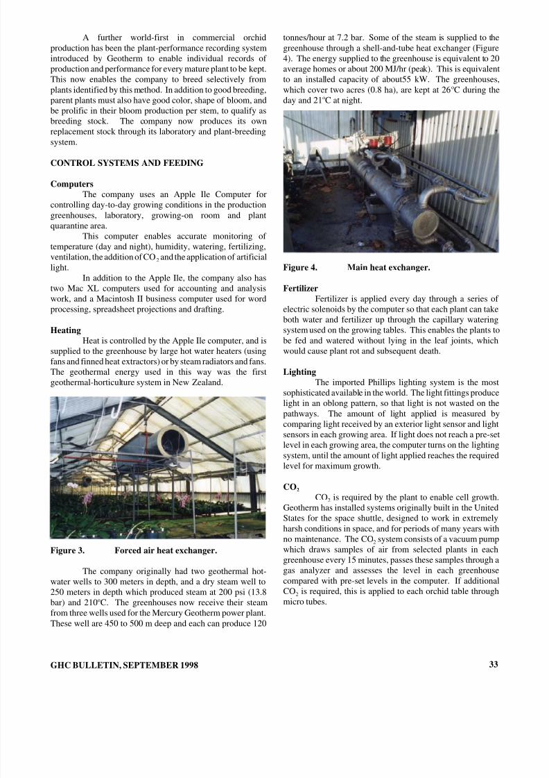
8/8/2019 September 1998 Geo-Heat Center Quarterly Bulletin
http://slidepdf.com/reader/full/september-1998-geo-heat-center-quarterly-bulletin 35/40
A further world-first in commercial orchidproduction has been the plant-performance recording systemintroduced by Geotherm to enable individual records of production and performance for every mature plant to be kept.This now enables the company to breed selectively fromplants identified by this method. In addition to good breeding,parent plants must also have good color, shape of bloom, andbe prolific in their bloom production per stem, to qualify asbreeding stock. The company now produces its ownreplacement stock through its laboratory and plant-breedingsystem.
CONTROL SYSTEMS AND FEEDING
ComputersThe company uses an Apple Ile Computer for
controlling day-to-day growing conditions in the productiongreenhouses, laboratory, growing-on room and plantquarantine area.
This computer enables accurate monitoring of temperature (day and night), humidity, watering, fertilizing,ventilation, the addition of CO 2 and the application of artificiallight.
In addition to the Apple Ile, the company also hastwo Mac XL computers used for accounting and analysiswork, and a Macintosh II business computer used for wordprocessing, spreadsheet projections and drafting.
HeatingHeat is controlled by the Apple Ile computer, and is
supplied to the greenhouse by large hot water heaters (usingfans and finned heat extractors) or by steam radiators and fans.The geothermal energy used in this way was the firstgeothermal-horticulture system in New Zealand.
Figure 3. Forced air heat exchanger.
The company originally had two geothermal hot-water wells to 300 meters in depth, and a dry steam well to250 meters in depth which produced steam at 200 psi (13.8bar) and 210 oC. The greenhouses now receive their steamfrom three wells used for the Mercury Geotherm power plant.These well are 450 to 500 m deep and each can produce 120
GHC BULLETIN, SEPTEMBER 1998
tonnes/hour at 7.2 bar. Some of the steam is supplied to thegreenhouse through a shell-and-tube heat exchanger (Figure4). The energy supplied to the greenhouse is equivalent to 20average homes or about 200 MJ/hr (peak). This is equivalentto an installed capacity of about55 kW. The greenhouses,which cover two acres (0.8 ha), are kept at 26 oC during theday and 21 oC at night.
Figure 4. Main heat exchanger.
FertilizerFertilizer is applied every day through a series of
electric solenoids by the computer so that each plant can takeboth water and fertilizer up through the capillary wateringsystem used on the growing tables. This enables the plants tobe fed and watered without lying in the leaf joints, whichwould cause plant rot and subsequent death.
LightingThe imported Phillips lighting system is the most
sophisticated available in the world. The light fittings producelight in an oblong pattern, so that light is not wasted on thepathways. The amount of light applied is measured bycomparing light received by an exterior light sensor and lightsensors in each growing area. If light does not reach a pre-setlevel in each growing area, the computer turns on the lightingsystem, until the amount of light applied reaches the requiredlevel for maximum growth.
CO 2
CO 2 is required by the plant to enable cell growth.Geotherm has installed systems originally built in the UnitedStates for the space shuttle, designed to work in extremelyharsh conditions in space, and for periods of many years withno maintenance. The CO 2 system consists of a vacuum pumpwhich draws samples of air from selected plants in eachgreenhouse every 15 minutes, passes these samples through agas analyzer and assesses the level in each greenhousecompared with pre-set levels in the computer. If additionalCO 2 is required, this is applied to each orchid table throughmicro tubes.
33

8/8/2019 September 1998 Geo-Heat Center Quarterly Bulletin
http://slidepdf.com/reader/full/september-1998-geo-heat-center-quarterly-bulletin 36/40
MARKETINGThe company has designed its packaging system to
enable the blooms to be displayed in the best possible manner.Extra cost is incurred by using boxes with a white interior andexterior, because white to Japanese symbolizes purity. Onlyfirst-grade flowers are exported, and every bloom (8-10 perstem) is inspected under a 10x magnifying light to ensure thatit is top quality. Approximately 55 blooms are packed perbox.
Shipments are from Taupo to Auckland by companytruck, and then by jet from Auckland to Tokyo. Time elapsedfrom picking to marketing is 3 days.
The company employs a manager and part-time staff in Tokyo. Blooms are sold every week through 25 outlets inJapan. Flowers are produced each week of the year, but arenot exported for two weeks at Christmas, and one other week which is a Buddhist “green week,” when only green coloreditems can be purchased by Buddhists. The majority of Japanese are Buddhists.
ELECTRIC POWER PLANTA geothermal electric power plant, operated by
Mercury Geotherm, Ltd., is located about one kilometer fromthe greenhouses. The greenhouses receive their steam supplyfor the power plant wells as mentioned earlier–wells #4, 5 and6 located in the Waiora Valley. The power plant has acapacity of 55 MW and was purchased from the NorthernCalifornia Water Board. California Governor Jerry Brownhad planned to installed the plant at the Geysers; but, this didnot happen. Instead, it was purchased, moved to New Zealandand commissioned in 1996.
34
Figure 5. Mercury Geotherm turbine-generatorbuilding.
Figure 6. Mercury Geotherm cooling tower.
GHC BULLETIN, SEPTEMBER 1998
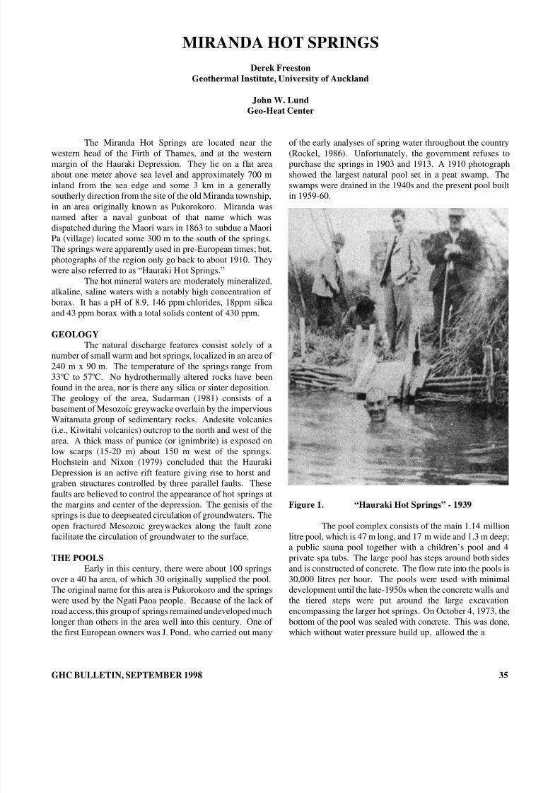
8/8/2019 September 1998 Geo-Heat Center Quarterly Bulletin
http://slidepdf.com/reader/full/september-1998-geo-heat-center-quarterly-bulletin 37/40
MIRANDA HOT SPRINGSDerek Freeston
Geothermal Institute, University of Auckland
John W. LundGeo-Heat Center
The Miranda Hot Springs are located near thewestern head of the Firth of Thames, and at the westernmargin of the Hauraki Depression. They lie on a flat areaabout one meter above sea level and approximately 700 minland from the sea edge and some 3 km in a generallysoutherly direction from the site of the old Miranda township,in an area originally known as Pukorokoro. Miranda wasnamed after a naval gunboat of that name which wasdispatched during the Maori wars in 1863 to subdue a MaoriPa (village) located some 300 m to the south of the springs.The springs were apparently used in pre-European times; but,photographs of the region only go back to about 1910. Theywere also referred to as “Hauraki Hot Springs.”
The hot mineral waters are moderately mineralized,alkaline, saline waters with a notably high concentration of borax. It has a pH of 8.9, 146 ppm chlorides, 18ppm silicaand 43 ppm borax with a total solids content of 430 ppm.
GEOLOGYThe natural discharge features consist solely of a
number of small warm and hot springs, localized in an area of 240 m x 90 m. The temperature of the springs range from33 oC to 57 oC. No hydrothermally altered rocks have beenfound in the area, nor is there any silica or sinter deposition.The geology of the area, Sudarman (1981) consists of abasement of Mesozoic greywacke overlain by the imperviousWaitamata group of sedimentary rocks. Andesite volcanics(i.e., Kiwitahi volcanics) outcrop to the north and west of thearea. A thick mass of pumice (or ignimbrite) is exposed onlow scarps (15-20 m) about 150 m west of the springs.Hochstein and Nixon (1979) concluded that the HaurakiDepression is an active rift feature giving rise to horst andgraben structures controlled by three parallel faults. Thesefaults are believed to control the appearance of hot springs atthe margins and center of the depression. The genisis of thesprings is due to deepseated circulation of groundwaters. Theopen fractured Mesozoic greywackes along the fault zonefacilitate the circulation of groundwater to the surface.
THE POOLSEarly in this century, there were about 100 springs
over a 40 ha area, of which 30 originally supplied the pool.The original name for this area is Pukorokoro and the springswere used by the Ngati Paoa people. Because of the lack of road access, this group of springs remained undeveloped muchlonger than others in the area well into this century. One of the first European owners was J. Pond, who carried out many
GHC BULLETIN, SEPTEMBER 1998
of the early analyses of spring water throughout the country(Rockel, 1986). Unfortunately, the government refuses topurchase the springs in 1903 and 1913. A 1910 photographshowed the largest natural pool set in a peat swamp. Theswamps were drained in the 1940s and the present pool builtin 1959-60.
Figure 1. “Hauraki Hot Springs” - 1939
The pool complex consists of the main 1.14 millionlitre pool, which is 47 m long, and 17 m wide and 1.3 m deep;a public sauna pool together with a children’s pool and 4private spa tubs. The large pool has steps around both sidesand is constructed of concrete. The flow rate into the pools is30,000 litres per hour. The pools were used with minimaldevelopment until the late-1950s when the concrete walls andthe tiered steps were put around the large excavationencompassing the larger hot springs. On October 4, 1973, thebottom of the pool was sealed with concrete. This was done,which without water pressure build up, allowed the a
35
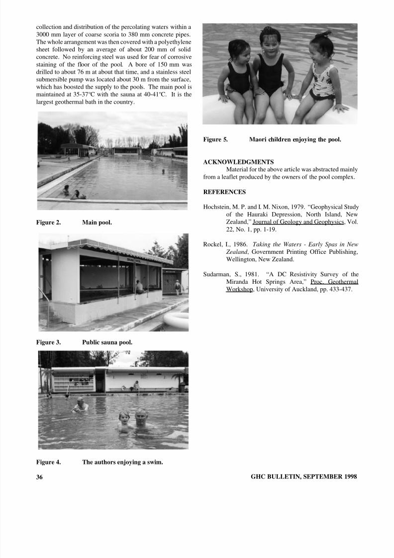
8/8/2019 September 1998 Geo-Heat Center Quarterly Bulletin
http://slidepdf.com/reader/full/september-1998-geo-heat-center-quarterly-bulletin 38/40
collection and distribution of the percolating waters within a3000 mm layer of coarse scoria to 380 mm concrete pipes.The whole arrangement was then covered with a polyethylenesheet followed by an average of about 200 mm of solidconcrete. No reinforcing steel was used for fear of corrosivestaining of the floor of the pool. A bore of 150 mm wasdrilled to about 76 m at about that time, and a stainless steelsubmersible pump was located about 30 m from the surface,which has boosted the supply to the pools. The main pool ismaintained at 35-37 oC with the sauna at 40-41 oC. It is thelargest geothermal bath in the country.
Figure 2. Main pool.
Figure 3. Public sauna pool.
Figure 4. The authors enjoying a swim.
36
Figure 5. Maori children enjoying the pool.
ACKNOWLEDGMENTSMaterial for the above article was abstracted mainly
from a leaflet produced by the owners of the pool complex.
REFERENCES
Hochstein, M. P. and I. M. Nixon, 1979. “Geophysical Studyof the Hauraki Depression, North Island, NewZealand,” Journal of Geology and Geophysics, Vol.22, No. 1, pp. 1-19.
Rockel, I., 1986. Taking the Waters - Early Spas in New Zealand , Government Printing Office Publishing,Wellington, New Zealand.
Sudarman, S., 1981. “A DC Resistivity Survey of theMiranda Hot Springs Area,” Proc. GeothermalWorkshop, University of Auckland, pp. 433-437.
GHC BULLETIN, SEPTEMBER 1998
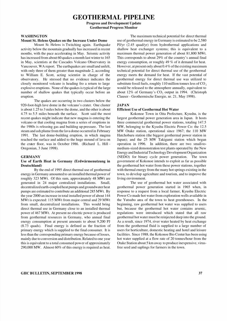
8/8/2019 September 1998 Geo-Heat Center Quarterly Bulletin
http://slidepdf.com/reader/full/september-1998-geo-heat-center-quarterly-bulletin 39/40
GEOTHERMAL PIPELINEProgress and Development Update
Geothermal Progress Monitor
WASHINGTONMount St. Helens Quakes on the Increase Under Dome
Mount St. Helens is Twitching again. Earthquakeactivity below the mountain gradually has increased in recentmonths, with the pace accelerating in May. Seismic activityhas increased from about 60 quakes a month last winter to 165in May, scientists at the Cascades Volcano Observatory inVancouver, WA report. The earthquakes are small and unfelt,with only three of them greater than magnitude 2, accordingto William E. Scott, acting scientist in charge of theobservatory. He stressed that no evidence indicates theclosely monitored volcano is heading fro a return to largeexplosive eruptions. None of the quakes is typical of the largenumber of shallow quakes that typically occur before aneruption.
The quakes are occurring in two clusters below the920-foot-high lave dome in the volcano’s crater. One clusteris about 1.25 to 3 miles below the dome, and the other is about4.75 to 5.5 miles beneath the surface. Scott said the mostrecent quakes might indicate that new magma is entering thevolcano or that cooling magma from a series of eruptions inthe 1980s is releasing gas and building up pressure. The laststeam and ash plume from the lava dome occurred in February1991. The last dome-building eruption, in which magmareached the surface and added to the huge mound of lava onthe crater floor, was in October 1986. (Richard L. Hill -Oregonian, 3 June 1998).
GERMANYUse of Earth Heat in Germany (Erdwärmenutzung inDeutschland)
By the end of 1995 direct thermal use of geothermalenergy in Germany amounted to an installed thermal power of roughly 323 MWt. Of this sum, approximately 48 MWt aregenerated in 24 major centralized installations. Small,decentralized earth-coupled heat pumps and groundwater heatpumps are estimated to contribute an additional 285 MWt. Bythe year 2000 an increase in total installed power of about 144MWt is expected: 115 MWt from major central and 29 MWtfrom small, decentralized installations. This would bringdirect thermal use in Germany close to an installed thermalpower of 467 MWt. At present no electric power is producedfrom geothermal resources in Germany, who annual finalenergy consumption at present amounts to about 9,200 PJ(8.73 quads). Final energy is defined as the fraction of primary energy which is supplied to the final consumer. It isless than the corresponding primary energy because of losses,mainly due to conversion and distribution. Related to one yearthis is equivalent to a total consumed power of approximately290,000 MW. Almost 60% of this energy is required as heat.
GHC BULLETIN, SEPTEMBER 1998
The maximum technical potential for direct thermaluse of geothermal energy in Germany is estimated to be 2,580PJ/yr (2.45 quad/yr) from hydrothermal applications andshallow heat exchanger systems; this is equivalent to amaximum thermal power generation of about 81,800 MWt.This corresponds to about 29% of the country’s annual finalenergy consumption, or roughly 49 % of it demand for heat.However, at present only about 0.4% of the existing maximumtechnical potential for direct thermal use of the geothermalenergy meets the demand for heat. If the vast potential of geothermal energy for direct thermal use was utilized tosubstitute fossil fuels, roughly 110 million tonnes less of CO 2
would be released to the atmosphere annually, equivalent toabout 12% of Germany’s CO 2 output in 1994. (ChristophClauser - Geothermische Energie, nr. 21, May 1998).
JAPANEfficient Use of Geothermal Hot Water
Kokonoe Town in Oita Prefecture, Kyushu, is thelargest geothermal power generation area in Japan. It hoststhree commercial geothermal power stations, totaling 147.5MW, belonging to the Kyushu Electric Power Co: the 12.5MW Otake station, operational since 1967; the 110 MWHatchobaru station (the biggest geothermal power station inJapan); and the 25 MW Takigami station which beganoperation in 1996. In addition, there are two small-to-medium-sized demonstration test plants operated by the NewEnergy and Industrial Technology Development Organization(NEDO) for binary cycle power generation. The towngovernment of Kokonoe intends to exploit as far as possiblethe geothermal hot water from these power stations, togetherwith thermal energy from the many hot springs existing in thetown, to develop agriculture and tourism, and to improve theliving environment.
The use of geothermal hot water associated withgeothermal power generation started in 1965 when, inresponse to a request from a local farmer, Kyushu ElectricPower Co made hot water from exploration wells available inthe Yutsubo area of the town to heat greenhouses. In thebeginning, raw geothermal hot water was supplied to usersbut, because the geothermal hot water contains arsenic,regulations were introduced which stated that all rawgeothermal hot water must be reinjected deep into the ground.As a result, since 1974, river water heated by heat exchangefrom the geothermal fluid is supplied to a large number of users for horticulture, domestic heating and hotel and leisurefacilities. Since 1988, the Kokonoe Bio Center has been usinghot water supplied at a flow rate of 20 tonnes/hour from theOtake Station about 5 km away to produce inexpensive, virus-free seed and saplings for farmers in the town.
37

8/8/2019 September 1998 Geo-Heat Center Quarterly Bulletin
http://slidepdf.com/reader/full/september-1998-geo-heat-center-quarterly-bulletin 40/40
A floriculture partnership organized by five farmersinvested JPY 153 million (approximately US$1.2 million) inconstructing an energy-saving rose farm consisting of 10greenhouses with a total floor area of 5,723 m 2 (1.4 acres).The farm grows roses all year round, and started shipments of flowers in 1984. The rose farm is provided with hot water(inlet temperature at 73 o C - 163 oF), exchanging heat withgeothermal hot water at a flow rate of 16 tonnes/hour. Thepartnership now enjoys sales of roses exceeding the planned
sum of JPY 38 million/year (approx. US$0.3 million/year)and completed the repayment of investment in 12 years.In 1994, a new floriculture partnership organized by
10 farmers began to grow roses in 20 newly-built greenhouseswith a total floor area of 19,278 m 2 (4.8 acres) usinggeothermal hot water. JPY 678 million (approx. US$5.2million) was invested in this new farm, which is expected tosell roses worth JPY 180 million (approx. US$1.4 million)annually. Because the supply of geothermal hot water to thenew farm is limited to 6 tonnes/hour, the farm receives hot
water in a storage tank and then circulates the water repeatedlythrough heating circuits (finned tubed radiators), therebymaking hot water at 50 oC (122 oF) flow through thegreenhouses at a rate of 37 tonnes/hour.
The changes in outdoor temperature at the site of therose farms are similar to those in colder, more northerlyregions. Thus, when the temperature inside the greenhousesis kept at 18 oC (64 oF) throughout a year, the degree-hours of heating are 60,210 oC-hours (4,516 oF-days). Each year, in
total, geothermal energy saves 884 kL (5,560 bbl) of fuel oiland JPY 41.5 million (approx. US$0.32 million) of fuel cost(fuel oil price at JPY 47/ L - US$1.37/gal).
Geothermal energy is also supplied to a muncipalcommunity center (75 oC - 167 oF at 3 tonnes/hour) and theprefectural recreational lodge for boys and girls (80 oC - 176 oFat 7 tonnes/hour). Waste water from all the uses is dischargedat 28 oC (82 oF) when the outside temperature is 8 oC (46 oF).(CADDET - Renewable Energy Newsletter, May, 1998).