sentinel a - fault passage indicator · range allows locating the fault arisen on the mv network,...
TRANSCRIPT

1
AMPEREMETRIC FAULT PASSAGE INDICATORS FOR OVERHEAD MV NETWORKS
FunctioningAmperemetric detection
The Overhead Sentinel-A measures the electromagnetic field and the electric field supplied by the
overhead line. The sensor integrated in the indicator provides an image of the residual current.
Other sensors provide an image of the line current flowing in the power grid and an image of the residual voltage.
Fault is detected when its value exceeds an adjustable threshold (homopolar residual current or phase current) for a fixed period.
SENTINEL A® - Fault Passage Indicator
Enedis APPROVED
Installed on poles of overhead lines, the Overhead-Sentinel-Arange allows locating the fault arisen on the MV network, whetherthey are single phase to earth, multi-phase, transient or permanent.It allows identifying quickly the failing section of network, bysuppling :• A blinking light for the permanent fault.• A counting of all events (transient or permanent).The Sentinel-A is an amperemetric fault passage indicator (FPI) adapted to the MV overhead lines (fault current always higher than capacitive current) :• Network with impedance earthing.• Network with direct earthing.
> DESCRIPTION
FRENCH PRODUCTION

2
OVE
RH
EAD
-SEN
TIN
EL-A
They differ from other defects by double colors (alternating Red and Green). Only detectors located between the high voltage station and the defect flash. The fault is located on the network section between the last FPI whose flashes and the first whose is not flashing.
Upstream faultDownstream fault
Service
To HV-MV Substation
Dual and multi-phase faults
Single phase earth faults
Upstream faultDownstream fault
Service
To HV-MV Substation
The single-phase earth faults are indicated with only one color light.Only detectors located between the high voltage station and the defect flash. The fault is located on the network section between the last FPI whose flashes and the first whose is not flashing
> FAULT LOCALIZATION

3
The information of the presence of a fault that led to the definitive trip of feeder is indicated locally by a LED. The signalling is performed at a rate of one flash per second :• Red flash in the event of a single-phase fault• Alternately red flash and green flash in the event of a multi-phase fault or double fault to earth
The Overhead-Sentinel-A, in addition with its functions of detection and signalling, counts and returns the number of transient faults, semi-permanent and permanent of different types (single phase and multi phase).A « human-machine interface » consisting of a display and push buttons allows the user: • Consultation of clear messages. • Visualization of 3 fault counters. • Configuration of different parameters and setting thresholds.
In option, a bluetooth radio remote control to access and configure the Overhead-Sentinel-A is available.It is fitted with the same keyboard than the local keyboard of the detector. Of a range of about twenty meters, remote control provides access to the same menu as the local display. It facilitates the configuration and consultation counters : • Without leaving the vehicle. • In inaccessible places .• When the detector is installed at more than 2 m high. It uses standard batteries (2 LR06 alkaline AA 1.5V).
> SIGNALLING FAULTS
Flashing information
Relay dedicated to remote control
Two relay outputs (dry potential free contacts) copy the light signalling. These contacts (NO) allow to bring back fault information to an external application.These contacts are activated for 100 ms to the appearance of transient fault then, if the fault becomes permanent, the contacts are activated for the duration of the light signalling.
Relay of alarm « Equipment fault »
A third relay output provides to an external application, information on the correct operation of the fault passage indicator. Two dry contacts («normally open» and «normally closed») are activated from the loss of supply of the fault passage indicator (end of autonomy of the rechargeable element - ultra capacitor - end of battery life) or in the event of processor failure (watchdog). It indicates that the detector is no longer operational : • the “NO” contact opens • the “NC” contact closes
> HUMAN MACHINE INTERFACE
METER READING

4
OVE
RH
EAD
-SEN
TIN
EL-A
7 to 14 m
3 to 6 m
Warning : The Overhead-Sentinel-A should not be installed in the following cases :
• On cross supports.
• On overhead-underground connection.
• On mix supports (with multiple networks HV, LV).
The Overhead-Sentinel-A is designed to be installed on electric poles of overhead lines. The supports can be concrete, wood or metal.
The box is fixed to the pole height between 3 m and 6 m (5 m being the default position).
The height between the floor and the lowest of the line wire shall be between 7 m and 14 m.
The pole must be free of all vegetation high on a radius of 3 meters around the support.
Warning :To maintain its sensitivity, the Overhead- Sentinel-A should not be installed :
• Less than 50 m from another MV line.
• Less than 200 m from HV line (<100kV) or railway.
• Less than 500 m from HV line (>100kV).
• Less than 50 m from an overhead-underground connection.
The Overhead-Sentinel-A must be installed at the center of the pole in the center of the overhead line :
Special case
For the use of Overhead-Sentinel-A on a double support, the detector must be installed on a crossbar between two poles.
> INSTALLATION

5
« Poly » (Multi-phase) Meter : 150 Day 1h51 min
« Poly » (Multi-phase) Meter : 40 Day 1h51 min
HV Substation
« Poly » (Multi-phase) Meter : 11 1 Year 163 Day
« Poly » (Multi-phase) Meter : 8120 Day 08h15 min
The buttons "↑" and "↓" allow scrolling the display of 2 fault counters. Once these were read, the user has the ability to perform their reset.
In addition to the default counters, the Overhead-Sentinel-A indicates the time since the last increment of each counter. This additional information :
• allows to know, after the extinction of the signals, if the Overhead-Sentinel-A has seen the fault.
• provides assistance for preventive maintenance of the HV line. When an unusual increase in the number of transient faults occurs, the Overhead-Sentinel-A provides valuable information on the section of the HV network causing these transient faults. With fault counters and this time information, it is possible to know which fault passage indicators have seen these faults and so, to identify the fault location before it causes a definitive trip.
The Overhead-Sentinel-A fault indicator is powered by ultra capacitor charged with solar panels. It does not require any replacement.
This version is equipped with a switch in order to turn off the current of the indicator if necessary.
Display of fault counters
Example of using the fault counters to find the section causing transient faults. With timers, it is easy to identify the faulty section :
> OPERATION
> POWER SUPPLY
Warning :When commissioning, the ultra capacitor of the overhead Sentinel A indicator needs to be charged.
In order to do so, 2 solutions are available :
• Place the overhead Sentinel A in full sun for at least 2 hours before commissioning (depending on the weather)
• Use the quick charge with the micro USB connector :
- By plugging a standard phone charger (the charger must supply a voltage of 5 V and a current greater or equal to 500 mA). This charger could be connected to the power supply or on a 12 V cigarette lighter socket.
- By plugging the indicator on the USB interface of the PC (with a USB-A cable / micro USB)
Charging time will be about 20 minutes. While charging, a red flash lights up and turns off at the end of the process.
6
OVE
RH
EAD
-SEN
TIN
EL-A
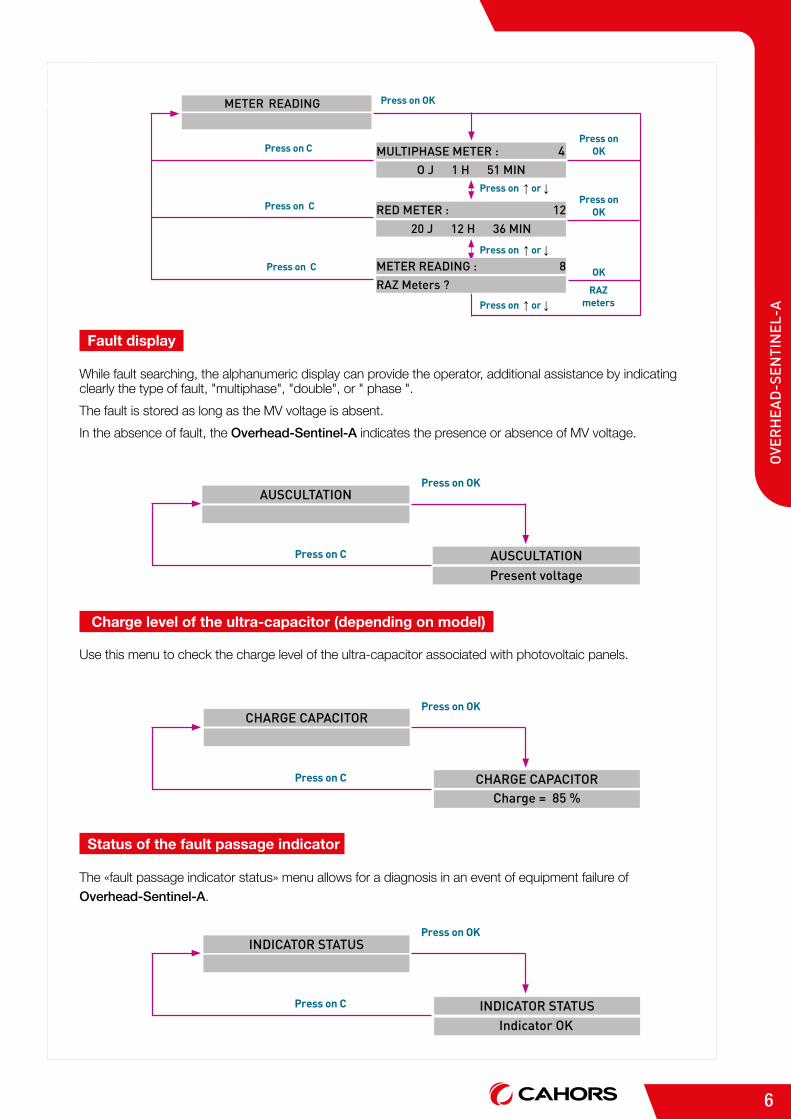
While fault searching, the alphanumeric display can provide the operator, additional assistance by indicating clearly the type of fault, "multiphase", "double", or " phase ".
The fault is stored as long as the MV voltage is absent.
In the absence of fault, the Overhead-Sentinel-A indicates the presence or absence of MV voltage.
Fault display
Use this menu to check the charge level of the ultra-capacitor associated with photovoltaic panels.
Status of the fault passage indicator
The «fault passage indicator status» menu allows for a diagnosis in an event of equipment failure of Overhead-Sentinel-A.
Charge level of the ultra-capacitor (depending on model)
Press on C
Press on OK
Press on OK
Press on ↑ or ↓
Press on ↑ or ↓
Press on ↑ or ↓
Press on OK
OK
RAZ meters
Press on C
Press on C
METER READING
MULTIPHASE METER : 4
RED METER : 12
METER READING : 8
O J 1 H 51 MIN
20 J 12 H 36 MIN
RAZ Meters ?
Press on C
Press on OKINDICATOR STATUS
INDICATOR STATUSIndicator OK
Press on C
Press on OKCHARGE CAPACITOR
CHARGE CAPACITOR Charge = 85 %
Press on C
Press on OKAUSCULTATION
AUSCULTATIONPresent voltage

7
MV NETWORK OVERHEAD-SENTINEL-A
Rated voltage UN Until 36 kV
Rated frequency 50 Hz
Detection of single- phase earth faults
Detection principle Amperemetric (threshold exceedance for a period)
Phase current detection threshold 20, 30, 40, 50, 60, 70, 80, 90, 100, 120, 140, 160, 180, 200, 220, 240 A
Handling time 60, 80, 100, 120, 140, 160, 180, 200, 220, 240, 280, 300, 400 ,500 ms
Signalling RED
Detection of dual single phase faults
Detection principle Amperemetric (threshold exceedance for a period)
Phase current detection threshold 250, 300, 350, 400, 450, 500, 600, 700 A
Handling time 60, 80, 100, 120, 140, 160, 180, 200, 220, 240, 280, 300, 400, 500 ms
Signalling RED and GREEN
Detection of multi-phase faults
Detection principle Amperemetric (threshold exceedance for a period)
Phase current detection threshold 250, 300, 350, 400, 450, 500, 600, 700 A
Handling time 60, 80, 100, 120, 140, 160, 180, 200, 220, 240, 280, 300, 400, 500 ms
Signalling RED and GREEN
Time delays
Before a fault is counted (T delay) 340 ms, 800 ms or 3 sec
Before the indication of a permanent fault (T permanent) 1 sec, 10 sec, 20 sec ou 70 sec
Voltage MV presence for «setting» the detection of single phase faults 5 sec
MV voltage return for clearing the current fault 5 sec
Indication
External indicator light High brightness flashing LEDs
External contact Closing dry contact
Indication stopped
Clearing the faultThrough MV voltage return
Voltage levelDelay
0.5 Un5 s
Stop of signalling with fault ever storedThrough a front panel pushbuttonAutomatically after a time delay
2h, 4h, 12h, 24h
> ELECTRICAL CHARACTERISTICS

8
OVE
RH
EAD
-SEN
TIN
EL-A
NORMS OVERHEAD-SENTINEL-A
Mechanical
Dimensions (W x H x D) 320 x 260 x 140 mm
Protection rating NF EN 60529NF EN 62262
IP 54 IK 09
Vibrations NF EN 68068-2-6Acceleration : 2g/
displacement : 0,15 mm (peak value) - 10 Hz to 500 Hz
Climatical
Operating temperature NF EN 60068-2-1NF EN 60068-2-2
- 25° C to + 55° C
Storage temperature NF EN 60068-2-14 - 40° C to + 70° C
Relative humidity NF EN 60068-2-3 Tests Ca - 93% à 40°C 96h closed box, 4h opened box
Salt mist NF EN 60068-2-11 178 h
Dielectric strength
Input voltage 12 V and dry contact ouputs compared to the box CEI 60255-5 2 kV - 50 Hz (1 mn)
5 kV shock (1,2/50 µs)
Electromagnetic
Dampened oscillating waves NF EN 61000-4-12 2.5 kV un common mode (100 kHz et 1 MHz)1 kV in differencial mode (100 kHz et 1 MHz)
Fast transients NF EN 61000-4-44 kV on power circuits 2 kV on other circuits
Shock waves NF EN 61000-4-5 1 kV coupling between wires2 kV coupling wire /ground
Electrostatic discharges NF EN 61000-4-2 Harshness 4 (8 kV contact discharge, 15 kV air discharge)
Electromagnetic field-amplitude NF EN 61000-4-3 10 V / m 27 MHz to 6 GHz
Power supply
Battery self-sufficiency 3 lithium batteries 13Ah format D (not included)
External supply 12V DC 12 V + 30% - 10%
Solar panels save by ultra-capacitor 2.5 V maintenance free (15 years)
MEDIUM VOLTAGE DIVISIONCRDE, a society of Groupe CAHORS
ZI des Grands Camps - BP 946090 Mercuès - FRANCE
Tél. +33 (0)5 65 30 38 10Fax +33 (0)5 65 20 09 17
> ENVIRONMENTAL CONDITIONS
CS 60022 • 46003 Cahors cedex 9 - FranceTél. +33 (0)5 65 35 82 20 • Fax +33 (0)5 65 35 82 52 www.cahors-ced.comwww.groupe-cahors.com
Réf
. 4.1
01.9
93R
13 -
08/
15 -
Doc
umen
t no
n co
ntra
ctue
l - C
réd
its p
hoto
s : C
AH
OR
S -
Fot
olia
- iS
tock
- G
oand
aR
éalis
atio
n : S
ervi
ce M
arke
ting
6
3
4
5
2
1
- 0
9/18